


Business Solutions
User Manual
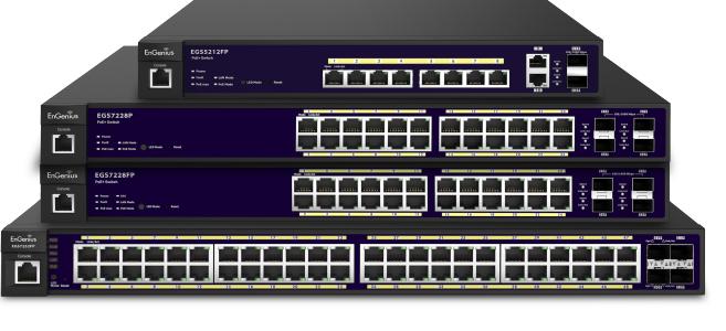
EGS5212FP | EGS7228P | EGS7228FP | EGS7252FP
version 1.0
Layer 2 Managed PoE+ Switch
IMPORTANT
To install your Switch please refer to the
Quick Installation Guide included in the product packaging.
2
Table of Contents
Chapter 1 Product Overview.................................................. |
6 |
Introduction/Package Contents................................................ |
7 |
Technical Specifications.............................................................. |
8 |
Physical Interface.......................................................................... |
11 |
Management Interface............................................................. |
14 |
Connecting the Switch to a Network.................................... |
15 |
Web Access...................................................................................... |
17 |
Chapter 2 Management........................................................ |
18 |
System/Search Bar........................................................................ |
19 |
- Summary........................................................................................ |
20 |
- IP Settings...................................................................................... |
21 |
- IPv4.................................................................................................. |
21 |
- IPv6.................................................................................................. |
23 |
- System Time................................................................................ |
24 |
- Port Settings............................................................................... |
26 |
- PoE/Power Budget..................................................................... |
28 |
- PoE Port Settings....................................................................... |
29 |
- EEE................................................................................................... |
32 |
L2 Features...................................................................................... |
33 |
- Link Aggregation........................................................................ |
33 |
- Port Trunking .............................................................................. |
35 |
- LACP Settings.............................................................................. |
36 |
- LACP Timout................................................................................. |
37 |
-MirrorSettings.............................................................................. |
38 |
- STP................................................................................................... |
40 |
- Global Settings........................................................................... |
41 |
- Spanning Tree Loops................................................................. |
42 |
- Root Bridge................................................................................ |
44 |
- Port Settings............................................................................... |
46 |
- CIST Instance Settings........................................................... |
48 |
- CIST Port Settings.................................................................... |
50 |
- MST Instance Setting.............................................................. |
52 |
- MST Port Settings..................................................................... |
54 |
- MAC Address Table...................................................................... |
56 |
- Static MAC Address................................................................. |
56 |
- Dynamic MAC Address........................................................... |
57 |
-LLDP.................................................................................................. |
58 |
- Global Settings.......................................................................... |
59 |
- Local Device............................................................................... |
60 |
- Remote Device.......................................................................... |
61 |
- IGMP Snooping.............................................................................. |
63 |
- Global Settings.......................................................................... |
64 |
- VLAN Settings.......................................................................... |
65 |
- Querier Settings....................................................................... |
66 |
- Group List..................................................................................... |
68 |
- Router Settings........................................................................ |
69 |
- MLD Snooping............................................................................... |
70 |
- Global Settings........................................................................... |
70 |
3
- VLAN Settings........................................................................... |
71 |
- Group List..................................................................................... |
72 |
- Router Settings........................................................................ |
73 |
- Jumbo Frame ............................................................................... |
74 |
VLAN................................................................................................ |
75 |
- 802.1Q.......................................................................................... |
75 |
- PVID................................................................................................ |
78 |
- Management VLAN................................................................. |
80 |
- Voice VLAN................................................................................ |
81 |
- Global Settings............................................................................ |
81 |
- OUI Settings................................................................................. |
82 |
- Port Settings................................................................................ |
83 |
Management................................................................................... |
84 |
- System Information................................................................... |
84 |
- User Management..................................................................... |
85 |
- File Management....................................................................... |
86 |
- Configuration Manager............................................................ |
86 |
- Dual Image..................................................................................... |
87 |
- SNMP............................................................................................... |
88 |
- Global Settings.............................................................................. |
90 |
- View List......................................................................................... |
91 |
- Group List........................................................................................ |
92 |
- Community List............................................................................ |
93 |
- User List......................................................................................... |
94 |
-Trap Settings/SNMP Traps........................................................ |
95 |
ACL...................................................................................................... |
97 |
- MAC ACL....................................................................................... |
98 |
- MAC ACE........................................................................................ |
99 |
- IPv4 ACL...................................................................................... |
100 |
-IPv4ACE........................................................................................ |
101 |
- IPv6 ACL....................................................................................... |
103 |
- IPv6 ACE....................................................................................... |
104 |
- ACL Binding................................................................................. |
106 |
QoS................................................................................................... |
107 |
- Global Settings.......................................................................... |
107 |
- CoS Mapping............................................................................... |
109 |
- DSCP Mapping............................................................................ |
110 |
- Port Settings.............................................................................. |
111 |
- Bandwidth Control.................................................................... |
112 |
- Storm Control............................................................................. |
113 |
Security.......................................................................................... |
114 |
-802.1X........................................................................................... |
114 |
- Global Settings........................................................................... |
115 |
- Port Settings.............................................................................. |
116 |
4
-AuthenticatedHost.................................................................. |
118 |
- Radius Server............................................................................ |
119 |
- Access.......................................................................................... |
121 |
- HTTP(S) Settings...................................................................... |
121 |
- Telnet Settings.......................................................................... |
122 |
- SSH Settings............................................................................... |
123 |
- Console Settings....................................................................... |
124 |
- Port Security............................................................................... |
125 |
- DoS................................................................................................. |
126 |
- Global Settings.......................................................................... |
126 |
- Port Settings.............................................................................. |
128 |
Monitoring...................................................................................... |
129 |
- Port Statistics............................................................................ |
129 |
-RMON............................................................................................. |
130 |
- Event List..................................................................................... |
130 |
-EventLogTable.......................................................................... |
131 |
- Alarm List.................................................................................... |
132 |
- History List.................................................................................. |
133 |
- History Log Table..................................................................... |
134 |
- Statistics...................................................................................... |
135 |
- Log.................................................................................................. |
136 |
-GlobalSettings............................................................................ |
137 |
-LocalLogging.............................................................................. |
138 |
- Remote Logging........................................................................ |
140 |
- Log Table...................................................................................... |
141 |
Diagnostics.................................................................................... |
142 |
- Cable Diagnostics...................................................................... |
142 |
- Ping Test/Ping Test Settings................................................ |
143 |
- IPv6 Ping Test........................................................................ |
144 |
- Trace Route............................................................................... |
145 |
Chapter 3 Maintenance....................................................... |
146 |
Maintenance............................................................................... |
147 |
Upgrading/Resetting............................................................... |
148 |
Rebooting/Logging Out......................................................... |
149 |
Appendix............................................................................... |
150 |
Quick Reference Guide............................................................. |
151 |
FCC Interference Statement.................................................. |
152 |
IC Interference Statement..................................................... |
153 |
CE Interference Statement..................................................... |
154 |
5

Chapter 1
Product Overview
6

Introduction
The EnGenius EGS series Layer 2 Switch is a device specially designed to support Access Points and IP Surveillance cameras, VOIP phones, and other PoE-Capable devices as well as other Ethernet-based networking equipment or computers.The EGS Switch provides simple, yet powerful
PoE manageability with features such as: IEEE 802.3af or IEEE 802.3at/af ports, PoE port management, loopback detection, and IGMP snooping.
Package Contents
Your EGS Layer 2 Switch package will contain the following items:*
•EnGenius Switch
•Power Cord
•RJ45 Console Cable
•Rack Mount Kit
•Quick Installation Guide
*(all items must be in package to issue a refund):
Maximum data rates are based on IEEE 802.3ab standards. Actual throughput and range may vary depending on distance between devices or traffic and bandwidth load in the network. Features and specifications subject to change without notice. Trademarks and registered trademarks are the property of their respective owners. For United States of America: Copyright
©2014 EnGenius Technologies, Inc. All rights reserved. Compliant with FCC - This equipment has been tested and found to comply with the limits for a Class A digital device, pursuant to Part 15 of the FCC Rules. These limits are designed to provide reasonable protection against harmful interference in a residential installation. This equipment generates, uses, and can radiate radio frequency energy and, if not installed and used in accordance with the instructions, may cause harmful interference to radio communications. Operation of this equipment in a residential area is likely to cause harmful interference in which case the user will be required to correct the interference at his/her own expense.
7
Technical Specifications
Standard:
|
EGS5212FP |
EGS7228P |
EGS7228FP |
EGS7252FP |
Ports on the front |
10 |
24 |
24 |
48 |
panel |
|
|
|
|
Power budget |
Ports 1 - 8, output up to 30 |
Ports 1 - 24, output up to |
Ports 1 - 24, output up |
Ports 1 - 48, output up |
|
Watts per Port |
30 Watts per Port |
to 30 Watts per Port |
to30 Watts per Port |
Total PoE Budget |
130 Watts |
185 Watts |
370 Watts |
740 Watts |
SFP Slots |
2 |
4 |
4 |
4 |
Switching Capacity: |
24 Gbps |
56 Gbps |
56 Gbps |
104 Gbps |
Forwarding Mode: |
|
Store and Forward |
|
|
Flash Memory: |
32 MB |
32 MB |
32 MB |
32 MB |
SD RAM: |
256 MB DDR3 |
256 MB DDR3 |
256 MB DDR3 |
256 MB DDR3 |
MAC Address Table: |
8K |
|
|
|
Jumbo Frame: |
9K |
|
|
|
8
Ports:
10, 24, or 48 10/100/1000 Mbps Ports in the front panel
(Depending on model)
2 or 4 100/1000Mbps SFP Ports (Depending on model)
1 RJ 45 Port
PoE Capability:
Supports IEEE 802.3at/af
PoE Capable Ports:
EGS5212FP - Port 1~8, output up to 30 Watts per port EGS7228P - Port 1~24, output up to 30 Watts per port EGS7228FP - Port 1~24, output up to 30 Watts per port EGS7252FP - Port 1~48, output up to 30 Watts per port
Total PoE Budget:
EGS5212FP 130 Watts, EGS7228P 185 Watts, EGS7228FP 370
Watts, EGS7252FP 740 Watts
Performance:
Switching Capacity:
EGS5212FP: 24Gbps
EGS7228P/EGS7228FP: 56Gbps
EGS7252FP: 104Gbps
Forwarding Mode: Store and Forward
Flash Memory: 32MB
SDRAM: 256MB DDR3
MAC Address Table: 8K
Jumbo Frame: 9K
LED Indicators
Device:
Power LED x1
Fault LED x1
PoE Max LED x1
RPS LED x1 (EGS7228FP only)
LAN Mode LED x1
PoE Mode LED x1
Copper Ports:
LAN/PoE Mode LED x 1
Link/Act LED x 1
SFP Ports:
Link/Act LED x 1
Environment & Mechanical:
Temperature Range
Operating: 32 to 122°F/0 to 50°C
Storage: -40 to 158°F/-40 to 70 °C
Humidity (non-condensing): 5% - 95%
9
L2 Features
802.3ad compatible Link Aggregation 802.1D Spanning Tree (STP) 802.1w Rapid Spanning Tree (RSTP)
802.1s Multiple Spanning Tree (MSTP)
IGMP Snooping v1/v2/v3 MLD Snooping
IGMP Fast Leave Port Trunking
Port Mirroring: One to one and many to one VLAN Group
Voice VLAN Queue
CoS based on 802.1p priority
CoS based on physical port CoS based on TOS
CoS based on DSCP BootP/DHCP Client Firmware Burn-Proof
802.1X Port-based Access Control
802.1X Guest VLAN
Port Security
Port Isolation
Storm Control Attack Prevention
Access Control List (ACL) Telnet Server
TFTP Client BootP/DHCP Client Web-based support SNMP v1 support SNMP v2c support SNMP v3 support
TFTP upgrade
Command Line Interface (CLI) SNTP
RMONv1
SYSLOG
Cable Diagnostics MIB Support RFC1213 RFC1493 RFC1757 RFC2674
PoE Management:
Power on/off per port
Power Class Configuration
Power feeding with priority
User-defined power limit
10
Physical Interface
Dimensions |
|
|
|
|
|
|
|
|
|
|
|
|
|
|
|
|
|
|
|
|
|
|
|
|
|
|
|
|
|
|
|
|
|
|
|
|
|
|
|
|
|
|
|
|
|
|
|
Dimensions |
|
|
|
|
|
|
|
|
|
|
|
|
|
|
|
|
|
|
|
|
|
|
|
|
|
|
|
|
|
|
|
|
|
|
|
|
|
|
|
|
|
|
|
|
|
||||||||||||||||
EGS5212FP |
|
|
|
|
|
|
|
|
|
|
|
|
|
|
|
|
|
|
|
|
|
|
|
|
|
|
|
|
|
|
|
|
|
|
|
|
|
|
|
|
|
|
|
|
|
|
|
EGS7228P |
|
|
|
|
|
|
|
|
|
|
|
|
|
|
|
|
|
|
|
|
|
|
|
|
|
|
|
|
|
|
|
|
|
|
|
|
|
|
|
|
|
|
|
|
|
|
|
||||||||||||||
Width: 13” |
|
|
|
Length: 9” |
|
|
|
|
|
|
|
|
|
|
|
|
Height: 1.73” |
|
Width: 10.2” Length: 17.32” Height: 1.73” |
|
|
|
|
|
|
|
|
|
|
|
|
|
|
|
|
|
|
|
|||||||||||||||||||||||||||||||||||||||||||||||||||||||||||||||||||||||
|
|
|
|
|
|
|
|
|
|
|
|
|
|
|
|
|
|
|
|
|
|
|
|
|
|
|
|
|
|
|
|
|
|
|
|
|
|
|
|
|
|
|
|
|
|
|
|
|
|
|
|
|
|
|
|
|
|
|
|
|
|
|
|
|
|
|
|
|
|
|
|
|
|||||||||||||||||||||||||||||||||||||
5 |
|
|
7 |
|
|
8 |
|
|
|
|
|
|
|
|
10 |
12 |
13 |
|
5 |
|
|
|
|
|
7 |
|
8 |
|
10 |
|
|
|
13 |
|
|||||||||||||||||||||||||||||||||||||||||||||||||||||||||||||||||||||||||||
2 |
|
|
|
|
|
|
|
|
|
|
|
|
|
|
|
|
|
|
|
|
|
|
|
|
|
|
|
|
|
|
|
|
|
|
|
|
|
|
|
|
|
|
|
|
|
|
|
|
|
|
|
2 |
|
|
|
|
|
|
|
|
|
|
|
|
|
|
|
|
|
|
|
|
|
|
|
|
|
|
|
|
|
|
|
|
|
|
|
|
|
|
|
|
|
|
|
|
|
|
|
|
|
|
|
|
|
|
|
||
|
|
|
|
|
|
|
|
|
|
|
|
|
|
|
|
|
|
|
|
|
|
|
|
|
|
|
|
|
|
|
|
|
|
|
|
|
|
|
|
|
|
|
|
|
|
|
|
|
|
|
|
|
|
|
|
|
|
|
|
|
|
|
|
|
|
|
|
|
|
|
|
|
|
|
|
|
|
|
|
|
|
|
|
|
|
|
|
|
|
|
|
|
|
|
|
|
|
|
|
|
|
|
|||||||
3 |
|
|
|
|
|
|
|
|
|
|
|
|
|
|
|
|
|
|
|
|
|
|
|
|
|
|
|
|
|
|
|
|
|
|
|
|
|
|
|
|
|
|
|
|
|
|
|
|
3 |
|
|
|
|
|
|
|
|
|
|
|
|
|
|
|
|
|
|
|
|
|
|
|
|
|
|
|
|
|
|
|
|
|
|
|
|
|
|
|
|
|
|
|
|
|
|
|
|
|
|
|
|
||||||||
1 |
|
|
|
|
|
|
|
|
|
|
|
|
|
|
|
|
|
|
|
|
|
|
|
|
|
|
|
|
|
|
|
|
|
|
|
|
|
|
|
|
|
|
|
|
|
|
|
|
|
|
|
|
1 |
|
|
|
|
|
|
|
|
|
|
|
|
|
|
|
|
|
|
|
|
|
|
|
|
|
|
|
|
|
|
|
|
|
|
|
|
|
|
|
|
|
|
|
|
|
|
|
|
|
|
|
|
|
|
|
|
|
|
|
|
|
|
|
|
|
|
|
|
|
|
|
|
|
|
|
|
|
|
|
|
|
|
|
|
|
|
|
|
|
|
|
|
|
|
|
|
|
|
|
|
|
|
|
|
|
|
|
|
|
|
|
|
|
|
|
|
|
|
|
|
|
|
|
|
|
|
|
|
|
|
|
|
|
|
|
|
|
|
|
|
|
|
|
|
|
|
|
|
|
|
|
|
|
|
|
|
|
|
|
|
|
|
|
|
||
4 |
|
|
|
|
|
|
6 |
|
|
|
|
|
|
|
|
|
|
|
|
|
|
|
|
|
|
|
|
|
|
|
|
|
|
|
|
|
|
|
|
|
|
|
|
|
|
|
|
|
|
|
|
|
|
|
|
|
|
|
|
|
|
|
|
|
|
|
|
|
|
|
|
|
|
|
|
|
|
|
|
|
|
|
|
|
|
|
|
|
|
|
|
|
|
|
|
|
|
|
|
|
|
|
|
|
|
|
|
|
|
|
|
|
|
|
|
|
|
|
|
|
|
|
|
|
|
|
|
|
|
|
|
|
|
|
|
|
|
|
|
|
|
|
|
|
|
|
|
|
|
|
|
|
|
|
|
|
|
|
|
|
|
|
|
|
|
|
|
|
|
|
|
|
|
|
|
|
|
|
|
|
|
|
|
|
|
|
|
|
|
|
|
|
|
|
|
|
|
|
|
|
|
|
|
|
|
|
|
|
|
|
|
|
|
|
|
|
|||
|
|
|
|
|
|
|
|
|
|
|
|
|
|
|
|
|
|
|
|
|
|
|
|
|
|
|
|
|
|
|
|
|
|
|
|
|
|
|
|
|
|
|
|
|
|
|
|
|
|
|
|
|
|
|
|
|
|
|
|
|
|
|
|
|
|
|
|
|
|
|
|
|
|
|
|
|
|
|
|
|
|
|
|
|
|
|
|
|
|
||||||||||||||||||||
|
|
|
|
|
|
|
|
|
|
|
|
|
|
|
|
|
|
9 |
|
|
|
|
|
|
|
|
|
|
|
|
|
|
|
|
|
|
|
|
|
|
|
||||||||||||||||||||||||||||||||||||||||||||||||||||||||||||||||||||
|
|
|
|
|
|
|
|
|
|
|
|
|
|
|
|
|
|
|
|
15 |
|
|
|
|
|
4 |
|
|
|
|
|
|
|
|
6 |
|
|
|
9 |
|
|
|
15 |
|
|
|
|||||||||||||||||||||||||||||||||||||||||||||||||||||||||||||||
|
|
|
|
|
|
|
|
|
|
|
|
|
|
|
|
|
|
|
|
|
|
|
|
|
|
|
|
|
|
||||||||||||||||||||||||||||||||||||||||||||||||||||||||||||||||||||||||||||||||
|
|
|
|
|
|
|
|
|
|
|
|
|
|
|
|
|
|
|
|
|
|
|
|
|
|
|
|
|
|
|
|
|
|
|
|
|
|
|
|
|
|
|
|
|
|
11 |
|
|
|
|
14 |
|
|||||||||||||||||||||||||||||||||||||||||||||||||||||||||
EGS5212FP - Front |
|
|
|
|
|
|
|
|
|
|
|
|
|
|
|
|
|
|
|
|
|
11 |
|
14 |
|
|
|
|
|
|
|
|
|
|
|
|
|
|
|
|
|
|
|
|
|
|
|
|
|
|
|
|
|
|
|
|
|
|
|
|
|
|
|
|
|
|
|
|
|
|
|
|
|
|
|
EGS7228P - Front |
|||||||||||||||||||||||||||||||||
|
|
|
|
|
|
|
|
|
|
|
|
|
|
|
|
|
|
|
|
|
|
|
|
|
|
|
|
|
|
|
|
|
|
|
|
|
|
|
|
|
|
|
|
|
|
|
|
16 |
|
|
|
|
|
|
|
|
|
|
|
|
|
|
|
|
|
|
|
|
|
|
|
|
|
|
|
|
|
|
|
|
|
|
|
|
|
|
16 |
|
|
|
|
|
|||||||||||||||||
|
|
|
|
|
|
|
|
|
|
|
|
|
|
|
|
|
|
|
|
|
|
|
|
|
|
|
|
|
|
|
|
|
|
|
|
|
|
|
|
|
|
|
|
|
|
|
|
|
|
|
|
|
|
|
|
|
|
|
|
|
|
|
|
|
|
|
|
|
|
|
|
|
|
|
|
|
|
|
|
|
|
|
|
|
|
||||||||||||||||||||||||
|
|
|
|
|
|
|
|
|
|
|
|
|
|
|
|
|
|
|
|
|
|
|
|
|
|
|
|
|
|
|
|
|
|
|
|
|
|
|
|
|
|
|
|
|
|
|
|
|
|
|
|
|
|
|
|
|
|
|
|
|
|
|
|
|
|
|
|
|
|
|
|
|
|
|
|
|
|
|
|
|
|
|
|
|
|
|
|
|
|
|
|
|
|
|
|
|
|
|
|
|
|
|
|
|
|
|
|
|
|
EGS5212FP - Back |
EGS7228P - Back |
11

Physical Interface
Dimensions
EGS7228FP
Width: 12.2” Length: 17.32” Height: 1.73”
5 |
|
7 |
|
8 |
10 |
13 |
|
|
2
3
1
4 |
|
|
|
6 |
|
|
|
|
|
|
|
|
|
15 |
|
|
|
|
|
|
|
|
|
|
|
|
|
|
|||
|
|
|
11 |
9 |
|
|
|
14 |
|||||||
|
|
|
|||||||||||||
EGS7228FP - Front
16
EGS7228FP - Back
12

Dimensions |
|
|
|
|
|
|
|
|
|
|
|
|
|
|
|
|
|
|
|
|
|
|
|
|
|
|
|
|
|
|
|
|
|
|
|
|
|
|
|
|
|
|
|
|
|
|
|
|
|
|
|
|
|
|
|
|
|
|
|
|
|
|
|
|
|
|
|
|
|
|
|
|
|
|
|
|
|
|
|
|
|
|
|
|
|
|
|||||||||||||||||||||||||
EGS7252FP |
|
|
|
|
|
|
|
|
|
|
|
|
|
|
|
|
|
|
|
|
|
|
|
|
|
|
|
|
|
|
|
|
|
|
|
|
|
|
|
|
|
|
|
|
|
|
|
|
|
|
|
|
|
|
|
|
|
|
|
|
|
|
|
|
|
|
|
|
|
|
|
|
|
|
|
|
|
|
|
|
|
|
|
|
|
|
|||||||||||||||||||||||||
Width: 17.32” |
|
Length: 16.14” |
|
|
|
Height: 1.73” |
|||||||||||||||||||||||||||||||||||||||||||||||||||||||||||||||||||||||||||||||||||||||||||||||||||||||||
2 |
|
|
|
|
|
|
|
|
|
|
|
|
|
|
|
|
|
|
|
|
|
|
|
|
|
|
|
|
|
|
|
|
|
|
|
|
|
|
|
|
|
|
|
|
|
|
|
|
|
|
|
|
|
|
|
|
|
|
|
|
|
|
|
|
|
|
|
|
|
|
|
|
|
|
|
|
|
|
|
|
|
|
|
|
|
|
|
|
|
|
|
|
|
|
|
|
|
|
|
|
|
|
|
|
|
|
|
|
|
|
|
|
|
|
|
|
|
|
|
|
|
|
|
|
|
|
|
|
|
|
|
|
|
|
|
|
|
|
|
|
|
|
|
|
|
|
|
|
|
|
|
|
|
|
|
|
|
|
|
|
|
|
|
|
|
|
|
|
|
|
|
|
|
|
|
|
|
|
|
|
|
|
|
|
|
|
|
|
|
|
|
|
|
|
|
|
|
|
|
|
|
|
|
|
|
|
|
|
|
|
|
|
|
|
|
|
|
|
|
|
|||
3 |
|
|
|
|
|
|
|
|
|
|
|
|
|
|
|
|
|
|
|
|
|
|
|
|
10 |
13 |
|
||||||||||||||||||||||||||||||||||||||||||||||||||||||||||||||||||||||||||||||||||||
|
|
|
|
|
|
|
|
|
|
|
|
|
|
|
|
|
|
|
|
|
|
|
|
||||||||||||||||||||||||||||||||||||||||||||||||||||||||||||||||||||||||||||||||||||||||
4 |
|
|
|
|
|
|
|
|
|
|
|
|
|
|
|
|
|
|
|
|
|
|
|
|
|
|
|
|
|
|
|
|
|
|
|
|
|
|
|
|
|
|
|
|
|
|
|
|
|
|
|
|
|
|
|
|
|
||||||||||||||||||||||||||||||||||||||||||||||||||||||
|
|
|
|
|
|
|
|
|
|
|
|
|
|
|
|
|
|
|
|
|
|
|
|
|
|
|
|
|
|
|
|
|
|
|
|
|
|
|
|
|
|
|
|
|
|
|
|
|
|
|
|
|
|
|
|
11 |
|
|
|
|
|
||||||||||||||||||||||||||||||||||||||||||||||||||
5 |
|
|
|
|
|
|
|
|
|
|
|
|
|
|
|
|
|
|
|
|
|
|
|
|
|
|
|
|
|
|
|
|
|
|
|
|
|
|
|
|
|
|
|
|
|
|
|
|
|
|
|
|
|
|
|
|
|
|
|
|
|
||||||||||||||||||||||||||||||||||||||||||||||||||
|
|
|
|
|
|
|
|
|
|
|
|
|
|
|
|
|
|
|
|
|
|
|
|
|
|
|
|
|
|
|
|
|
|
|
|
|
|
|
|
|
|
|
|
|
|
|
|
|
|
|
|
|
|
|
|
|
|
|
|
|
|
|
|
|
|
|
|
|
|
|
|
|
|
|
|
|
|
|
|
|
|
|
|
|
|
|
|
|
|
|
|
|
|
|
|
|
|
|
|
|
|
|
|
|
|
|
|
|
|
||
|
|
|
|
|
|
|
|
|
|
|
|
|
|
|
|
|
|
|
|
|
|
|
|
|
|
|
|
|
|
|
|
|
|
|
|
|
|
|
|
|
|
|
|
|
|
|
|
|
|
|
|
|
|
|
|
|
|
|
|
|
|
|
|
|
|
|
|
|
|
|
|
|
|
|
|
|
|
|
|
|
|
|
|
|
|
|
|
|
|
|
|
|
|
|
|
|
|
|
|
|
|
|
|
|
|
|
|
||||
6 |
|
|
|
|
|
|
|
|
|
|
|
|
|
|
|
|
|
|
|
|
|
|
|
|
|
|
|
|
|
|
|
|
|
|
|
|
|
|
|
|
|
|
|
|
|
|
|
|
|
|
|
|
|
|
|
|
|
|
|
|
|
|
|
|
|
|
|
|
|
|
|
|
|
|
|
|
|
|
|
|
|
|
|
|
|
|
|
|
|
|
|
|
|
|
|
|
|
|
|
|
|
|
|
|
|
|
|
|
|
|
|
1 |
|
|
|
|
|
|
|
|
|
|
|
|
|
|
|
|
|
|
|
|
|
|
|
|
|
|
|
|
|
|
|
|
|
|
|
|
|
|
|
|
|
|
|
|
|
|
|
|
|
|
|
|
|
|
|
|
|
|
|
|
|
|
|
|
|
|
|
|
|
|
|
|
|
|
|
|
|
|
|
|
|
|
|
|
|
|
|
|
|
|
|
|
|
|
|
|
|
|
|
|
|
|
|
|
|
|
|
|
|
|
|
|
|
|
|
|
|
|
|
|
|
|
|
|
|
|
|
|
|
|
|
|
|
|
|
|
|
|
|
|
|
|
|
|
|
|
|
|
|
|
|
|
|
|
|
|
|
|
|
|
|
|
|
|
|
|
|
|
|
|
|
|
|
|
|
|
|
|
|
|
|
|
|
|
|
|
|
|
|
|
|
|
|
|
|
|
|
|
|
|
|
|
|
|
|
|
|
|
|
|
|
|
|
|
|
|
|
|
|
|
|
|
|
|
|
|
|
|
|
|
|
|
|
|
|
|
|
|
|
|
|
|
|
|
|
|
|
|
|
|
|
|
|
|
|
|
|
|
|
|
|
|
|
|
|
|
|
|
|
|
|
|
|
|
|
|
|
|
|
|
|
|
|
|
|
|
|
|
|
|
|
|
|
|
|
|
|
|
|
|
|
|
|
|
|
|
|
|
|
|
|
|
|
|
|
|
|
|
|
|
|
|
|
|
|
|
|
|
|
|
|
|
|
|
|
7 |
|
|
|
|
|
|
|
|
|
|
|
|
|
|
|
|
|
|
|
|
|
|
|
|
|
|
|
|
|
|
|
|
|
|
|
|
|
|
|
|
|
|
|
|
|
|
|
|
|
|
|
|
|
|
|
|
|
|
|
|
|
|
|
|
|
|
|
|
|
|
|
|
|
|
|
|
|
|
|
|
|
|
|
|
|
|
|
|
|
|
|
|
|
|
|
|
|
|
|
|
|
|
|
|
|
|
|||||
|
|
|
|
|
|
|
|
|
|
|
|
|
|
|
|
|
|
|
|
|
|
|
|
|
|
|
|
|
|
|
|
|
|
|
|
|
|
|
|
|
|
|
|
|
|
|
|
|
|
|
|
|
|
|
|
|
|
|
|
|
|
|
|
|
|
|
|
|
|
|
|
|
|
|
|
|
|
|
|
|
|
|
|
|
|
|
|
|
|
|
|
|
|
|
|
|
|
|
|
|
|
|
|
|
|
||||||
|
|
|
|
|
|
|
|
|
|
|
|
|
|
|
|
|
|
|
|
9 |
|
|
|
|
|
|
|
|
|
|
|
|
|
|
|
|
|
|
|
|
|
|
|
|
|
|
|
|
|
|
|
|
|
|
|
|
|
|
|
|
|
|
|
|
|
|
|
|
|
|
|
|
|
|
|||||||||||||||||||||||||||||||||||||
|
|
|
|
|
|
|
|
|
|
|
|
|
|
|
|
|
|
|
|
|
|
|
|
|
|
|
|
|
|
|
|
|
|
|
|
|
|
|
|
|
|
|
|
|
|
|
|
|
|
|
|
|
|
|
|
|
|
|
|
|
|
|
|
|
|
|
|
|
|
|
|
|
|
15 |
|||||||||||||||||||||||||||||||||||||
|
|
|
|
|
|
|
|
|
|
|
|
|
|
|
|
|
EGS7252FP - Front |
|
|
|
|
|
|
|
|
|
|
|
|
|
|
|
|
|
|
|
|
|
|
|
|
|
|
|
|
|
|
|
|
|
|
|
|
|
|
|
|
|
|
|
|
|
|
|
|
|
|
|
|
|
|
||||||||||||||||||||||||||||||||||||||||
8 |
|
|
|
|
|
|
|
|
|
|
|
|
|
|
|
|
|
|
|
|
|
|
|
|
|
|
|
|
|
|
|
|
|
|
|
|
|
|
|
|
|
|
|
|
|
|
|
|
|
|
|
|
|
|
|
|
|
|
|
|
|
|
|
|
|
|
|
|
|
|
|
|
|
|
|
|
|
|
|
|
|
|
|
|
|
|
|
|
|
|
|
|
|
|
|
|
|
|
|
|
|
|
|||||||||
|
|
|
|
|
|
|
|
|
|
|
|
|
|
|
|
|
|
|
|
|
|
|
|
|
|
|
|
|
|
|
|
|
|
|
|
|
|
|
|
|
|
|
|
|
|
|
|
14 |
|
|
|
|
|||||||||||||||||||||||||||||||||||||||||||||||||||||||||||
|
|
|
|
|
|
|
|
|
|
|
|
|
|
|
|
|
|
|
|
|
|
|
|
|
|
|
|
|
|
|
|
|
|
|
|
|
|
|
|
|
|
|
|
|
|
|
|
|
|
|
|
|
|
|
|
|
|
|
|
|
|
||||||||||||||||||||||||||||||||||||||||||||||||||
1RJ45 Console Port
2Power LED: Light off = Power off; Solid Light = Power On.
3Fault LED: Light off = Normal Behavior; Solid Light = Error.
4PoE Max LED: Light off = Additional PoE device may still be added; Solid Light = The PoE device’s output power has exceeded total PoE limit. No additional devices can be powered on via PoE.
5LAN Mode LED: Light off = LAN mode is not activated; Solid Light
=LAN mode is activated.
6PoE Mode LED: Light off = PoE mode is not activated; Solid Light
=PoE mode is activated.
7LED Mode Selector: Press to change between LAN and PoE mode. 8 Reset Button: Press to reset the device to factory default settings.
9RJ-45 LAN Ports: 10/100/1000 Mbps RJ-45 LAN ports.
10LAN Mode LED (Per Copper Port): Light off = No link is
16
EGS7252FP -Back
established on the port; Solid Amber Light = A valid 10/100 Mpbs link is established on the port; Solid Green Light = A valid 1000 Mbps link is established on the port.
11 Link/Act LED (Per Copper Port): Light off = No link is established on the port; Solid Light = A valid link is established on the port; Blinking Light = Packet transmission on the port.
12 Uplink Ports: Gigabit Ports
13 SFP Ports: Small form factor pluggable ports.
14 Speed LED (Per SFP Port)
15 Link/Act LED (Per SFP Port): Light off = No link is established on the port; Solid Amber Light: A valid 100 Mpbs link is established on the port; Solid Green Light: A valid 1000 Mbps link is established on the port.
16 Power Connector
13
Management Interface
The EGS Layer 2 PoE+ Switch features an embedded Web interface for the monitoring and management of your device.
14
Connecting the Switch to a Network
Discovery in a Network with a DHCP Server
Use this procedure to setup the Switch within a network that uses DHCP.
1.Connect the supplied Power cord to the Switch and plug the other end into an electrical outlet. Verify the power LED indicator is lit on the Switch.
2.Wait for the Switch to complete booting up. It might take a minute for the Switch to completly boot up.
3.Connect one end of a Category 5/6 Ethernet cable into the Gigabit (10/100/1000) Ethernet port on the Switch front panel and the other end to the Ethernet port on the computer.VerifythattheLEDontheEthernetportsofthe Switch are green.
4.Once your computer is on, ensure that your TCP/IP is set to On or Enabled. Open Network Connections and then click Local Area Connecton. Select Internet Protocol Version 4 (TCP/IPv4). If your computer is already on a network,ensurethatyouhavesetittoaStaticIPAddress ontheInterface(Example:192.168.0.10andtheSubnet mask address as 255.255.255.0).
5.Open a web browser on your computer. In the address bar of the web browser, enter 192.168.0.239 and click
Enter.
6.A login screen will appear. By default, the username is admin and the password is password. Enter the current password of the Switch and then click
Login.
7.Once logged in, click IP Settings under the System tab and select IPv4 or IPv6. Next,
8.Click DHCP under Auto-Configuration.
9.Click Apply to save the settings.
10.Connect the Switch to your network (DHCP enabled).
11.On the DHCP server, find and write down the IP address allocated to the device. Use this IP address to access the management interface.
IP Address: ________________________________________
15
Discovery on a Network without a DHCP Server
This section describes how to set up the EGS Layer 2 Switch in a network without a DHCP server. If your network has no DHCP service, you must assign a static IP address to your Switch in order to log in to the web-based Switch management.
1.Connect the supplied Power cord to the Switch and plug the other end into an electrical outlet. Verify the Power LED indicator is lit on the Switch.
2.Wait for the Switch to complete booting up. It might take a minute or so for the Switch to completely boot up.
3.Connect one end of a Category 5/6 Ethernet cable into the Gigabit (10/100/1000) Ethernet port on the Switch front panel and the other end to Ethernet port on the computer. Verify that the LED on Ethernet ports of the Switch are green.
4.Once your computer is on, ensure that your TCP/IP is set to On or Enabled. Open Network Connections and then click Local Area Connecton. Select Internet Protocol Version 4 (TCP/IPv4).
5.If your computer is already on a network, ensure that you have set it to a Static IP Address on the Interface
(Example: 192.168.0.10 and the Subnet mask address as 255.255.255.0).
6.Open a web browser on your computer. In the address bar of the web browser, enter 192.168.0.239 and click
Enter.
7.A login screen will appear. By default, the username isadminandthepasswordispassword.Enterthecurrent password of the Switch and then click Login.
To make access to the web-based management interface more secure, it’s highly reccomended that you change the password to something more unique.
8.Once logged in, click IP Settings under the System menu and select Static IP to configure the IP settings of the management interface.
9.Enter the IP address, Subnet mask, and Gateway.
10.Click Apply to update the system.
16
Web Access
Use this procedure to access the management interface through a Web browser for device configuration.
1.Open a Web browser on your computer and enter the following address (default): http://192.168.0.239.
2.On the login screen, use the following information: Username: admin
Password: password
To make access to the web-based management interface more secure, it’s highly reccomended that you change the password to something more unique.
17
Chapter 2
Management
18

System
The navigation pane at the left of the Web browser interface contains a System tab that enables you to manage your EGS Layer 2 Switch with features under the following main menu options:
•“System”
•“L2 Features”
•“VLAN”
•“Management”
•“ACL”
•“QoS”
•“Security”
•“Monitoring”
•“Diagnostics”
The description that follows in this chapter describes configuring and managing the system settings within the
Switch.
Search Bar
At the top right corner of the Graphical User Interface (GUI) is the search bar which you can use to find and jump to any of the L2 management features. When you type in a word, all possible results for that word in the navigation pane will appear. Click on the results from the drop down list to open that management tab.
19
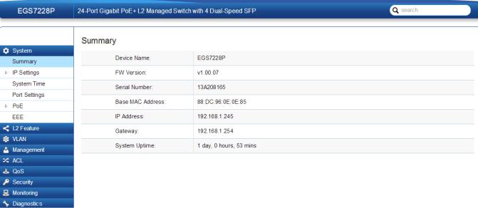
Summary
The Summary screen contains general device information about the Switch, including the device name, Firmware version, MAC address, IP address, Gateway, and System Uptime.
Device Name: |
Displays the model name of the Switch |
FW version: |
Displays the installed firmware version of the |
|
Switch. |
Serial Number: |
Displays the serial number of the Switch. |
Base MAC address: |
Displays the MAC address of the device. |
IP Address: |
Displays the IP address assigned by DHCP |
|
server. |
Gateway: |
Displays the Gateway of IP interface. |
System Uptime: |
Displays the amount of time since the most |
|
recent device reset. The System Time is |
|
displayed in the following format: days, |
|
hours, and minutes. For example, the display |
|
will read: 3 days, 6 hours, 10 minutes. |
|
|
20
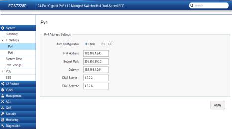
IP Settings
The IP Setting screen contains fields for assigning IP addresses. IP addresses are either defined as static or are retrieved using the Dynamic Host Configuration Protocol
(DHCP). DHCP assigns dynamic IP addresses to devices on a network. DHCP ensures that network devices can have a different IP address every time the device connects to the network.
Note the following when configuring IP Addresses:
If the device fails to retrieve an IP address through DHCP, the default IP address is 192.168.0.239.
IPv4
Select whether to you wish to enable Static or DHCP for
Auto-Configuration. Next, enter the information for the IP address, gateway, and DNS servers.
To be managed over the network, the Switch needs an IP Address to be assigned. The IP Settings screen contains fields for assigning IP addresses. IP addresses are either defined as Static or are retrieved using the Dynamic Host Configuration Protocol (DHCP). DHCP assigns dynamic IP addresses to devices on a network. DHCP ensures that network devices have a different IP address every time the device connects to the network.
To access the page, click IP Settings under the System menu.
 Important: If the device fails to retrieve an IP address through DHCP, the default IP address is: 192.168.0.239 and the factory default subnet mask is:
255.255.255.0.
To access the page, click IPv4 under IP Settings in the
System menu.
21
Dynamic IP Address (DHCP): |
EnablestheIPaddresstobeconfigured |
|
automatically by the DHCP server. |
|
Select this option if you have a DHCP |
|
server that can assign the Switch an IP |
|
address, subnet mask, default gateway |
|
IP address, and a domain name server |
|
IP address automatically. Selecting this |
|
field disables the IP Address, Subnet |
|
mask,and Gatewayfields. |
Static IP Address: |
Allows the entry of an IP address, |
|
subnet mask, and a default gateway |
|
for the Switch. Select this option if |
|
you don’t have a DHCP server or if |
|
you wish to assign a static IP address |
|
to the Switch. |
IP Address: |
This field allows the entry of an |
|
IPv4 address to be assigned to this |
|
IP interface. Enter the IP address |
|
of your Switch in dotted decimal |
|
notation. The factory default value |
|
is: 192.168.0.239. |
Subnet Mask: |
A Bitmask that determines the |
|
extent of the subnet that the Switch |
|
is on. This should be labeled in the |
|
form: xxx.xxx.xxx.xxx, where each |
|
xxx is a number (represented in |
|
decimals) between 0 and 255. The |
|
value should be 255.0.0.0 for a Class |
|
A network, 255.255.0.0 for a Class |
|
B network, and 255.255.255.0 for a |
|
Class C network, but custom subnet |
|
masks are allowed. Enter the IP |
|
subnet mask of your Switch in dotted |
|
decimal notation. The factory default |
|
value is: 255.255.255.0. |
Gateway: |
Enter an IP address that determines |
|
where packets with a destination |
|
address outside the current subnet |
|
should be sent. This is usually the |
|
address of a router or a host acting |
|
as an IP gateway. If your network |
|
is not part of an Intranet, or you do |
|
not want the Switch to be accessible |
|
outside your local network, you can |
|
leave this field blank. |
DNS Server (Domain Name |
Used for mapping a domain name |
System): |
to its corresponding IP address and |
|
vice versa. Enter a DNS IP address |
|
in order to be able to use a domain |
|
name to access the Switch instead |
|
of using an IP address. |
Apply: Click APPLY to update the the system settings.
22

IPv6
IPv6 is a an upgraded version to IPv4, providing more available IP addresses as well as other benefits. To access the switch over an IPv6 network you must first configure it with IPv6 information (IPv6 prefix, prefix length, and default gateway). To configure IPv6 for the Switch, select whether to you wish to enable Auto-Configura- tion, Static, or DHCP for the IPv6 State. Next, enter the information for the IP address, range, and gateway.
IPv6 State: |
Select whether you wish to enable Auto |
|
Configuration, DHCPv6 Client, or Static for |
|
the IPv6 address. |
Auto Configuration: |
Use this option to set the IPv6 address for |
|
the IPv6 network interface in Auto Con- |
|
figuration. The Switch will automatically |
|
generate and use a globally-unique IPv6 |
|
address based on the network prefix and |
|
its Ethernet MAC address. |
DHCPv6 Client: |
This enables the IP address to be config- |
|
ured automatically by the DHCP server. |
|
Select this option if you have an IPv6 |
|
DHCP server that can assign the Switch |
|
an IPv6 address/Prefix and a default gate- |
|
way IP address. |
Static: |
Allows the entry of an IPv6 address/Pre- |
|
fix and a default gateway for the Switch. |
|
Select this option if you wish to assign |
|
static IPv6 address information to the |
|
Switch. |
IPv6 Address: |
This field allows the entry of an IPv6 |
|
address/Prefix to be assigned to this IP |
|
interface. |
Gateway: |
Set the default gateway IPv6 address for |
|
the interface. Enter the default gateway |
|
IPv6 address. |
Apply: Click APPLY to update the system settings.
23

System Time
Use the System Time screen to view and adjust date and time settings.
The Switch supports Simple Network Time Protocol (SNTP). SNTP assures accurate network device clock time synchronization up to the millisecond. Time synchronization is performed by a network SNTP server. This software operates only as an SNTP client and cannot provide time services to other systems.
Current time: |
Displays the current time. |
|
Enable SNTP: |
Select whether to Enable or |
|
|
Disable the SNTP server. The |
|
|
system time is set via an SNTP |
|
|
sever. |
|
Time Zone: |
Select the difference between |
|
|
Greenwich Mean |
Time (GMT) |
|
and local time. |
|
Daylight Savings Time: |
Select between |
Recurring or |
|
Non-recurring. |
|
Daylight Savings Time Offset: |
Enter the time of Daylight |
|
|
Savings Time Offset. |
|
Recurring From: |
Select the Day, Week, Month, |
|
|
and Hour from the list. |
|
Recurring To: |
Select the Day, Week, Month, |
|
|
and Hour from the list. |
|
SNTP/NTP Server Address: |
Enter the SNTP or NTP sever IP |
|
|
address or hostname. |
|
Server Port: |
Displays the time sever port. |
|
24
To configure date/time through SNMP:
1.Next to the Enable SNTP, select Enable.
2.In the Time Zone Offset list, select by country or by the Coordinated Universal Time (UTC/GMT) time zone in which the Switch is located.
3.Next select Disabled, Recurring, or Non-Recurring for Daylight Savings Time. Daylight saving is a period from late spring to early fall when many countries set their clocks ahead of normal local time by one hour to give more daytime light in the evening.
4.In the SNTP/NTP Server Address field, enter the IP address or the host name of the SNTP/NTP server.
5.Finally, enter the port number on the SNTP server to which SNTP requests are sent. The valid range is from 1–65535. The default is: 123.
6.Click APPLY to update the system settings.
To configure date/time manually:
1.Next to the Enable SNTP, select Disable.
2.In the Manual Time field, use the drop-down boxes to manually select the date and time you wish to set.
3.In the Time Zone Offset list, select by country or by the Coordinated Universal Time (UTC/GMT) time zone in which the Switch is located.
4.Next select Disabled, Recurring or Non-recurring for Daylight Savings Time. Daylight saving is a period from late spring to early fall when many countries set their clocks ahead of normal local time by one hour to give more daytime light in the evening.
5.Click APPLY to update the system settings.
25

Port Settings
Use this screen to view and configure Switch port settings. The Port Settings feature lets you change the configuration of the ports on the Switch in order to find the best balance of speed and flow control according to your preferences. Configuring Gigabit ports require additional factors to be considered when arranging your preferences for the Switch compared to 10/100 ports.
To access the page, click Port Settings under the System menu.
Port: Displays the port number.
Link Status: Indicates whether the link is up or down.
Mode: Select the speed and the duplex mode of the Ethernet connection on this port.
Selecting Auto (Auto-Negotiation) allows one port to negotiate with a peer port automatically to obtain the connection speed and duplex mode that both ends support. When auto-negotiation is turned on, a port on the Switch negotiates with the peer automatically to determine the connection speed and duplex mode. If the peer port does not support autoegotiation or turns off this feature, the Switch determines the connection speed by detecting the signal on the cable and using half duplex mode. When the Switch’s auto-negotiation is turned off, a port uses the pre-configured speed and duplex mode when making a connection, thus requiring you to make sure that the settings of the peer port are the same in order to connect.
26

Flow Control: A concentration of traffic on a port decreases port bandwidth and overflows buffer memory causing packet discards and frame losses. Flow Control is used to regulate transmission of signals to match the bandwidth of the receiving port. The Switch uses IEEE802.3x flow control in full duplex mode and backpressure flow control in half duplex mode.
IEEE802.3x flow control is used in full duplex mode to send a pause signal to the sending port, causing it to temporarily stop sending signals when the receiving port memory buffers fill.
Back Pressure flow control is typically used in half duplex mode to send a “collision” signal to the sending port (mimicking a state of packet collision) causing the sending port to temporarily stop sending signals and resend later.
Click APPLY to update the system settings.
27
PoE
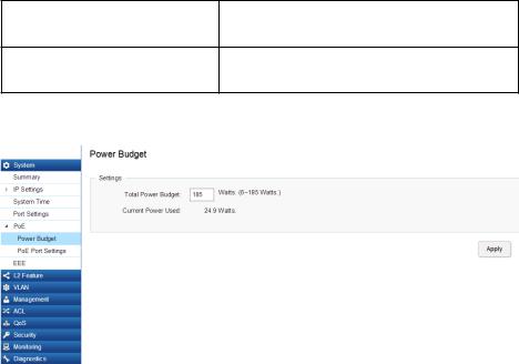
Power Budget
The PoE Management screen contains system PoE information for monitoring the current power usage and assigns the total amount of power the Switch can provide to all of its PoE ports. Ports 1~8, 24, or 48 on the Switch are IEEE802.3at/af compliant ports. Each port is capable of delivering up to 30 Watts and a total PoE budget of either
130, 185, 370 or 740 Watts depending on your model for uninterrupted PoE use. To access the page, click PoE under the System menu.
|
Ports |
Power Budget |
EGS5212FP |
8 |
130 Watts |
EGS7228P |
24 |
185 Watts |
EGS7228FP |
24 |
370 Watts |
EGS7252FP |
48 |
740 Watts |
Total Power Budget: Enter the amount of power the Switch can provide to all ports.
Consumed Power: Shows the total amount of power currently being delivered to all ports.
Apply: Click APPLY to update the the system settings.
28
PoE Port Settings
The EnGenius Layer 2 PoE+ Switches supports Power over Ethernet (PoE) as defined by the IEEE 802.3af and 802.3at. All ports can support PoE up to 30W. Ports 1-24 can supply about 48 VDC power to Powered Devices (PDs) over standard UTP Ethernet cables. The Switch follows the standard PSE (Power Sourcing Equipment) pinout, whereby power is sent out over pins 1, 2, 3 and 6.
EGS5212FP: Ports 1-8 supports both IEEE802.3 af and at. The maximum power budget is 130 Watts.
EGS7228P: Ports 1-24 supports both IEEE802.3 af and at. The maximum power budget is 185 Watts.
EGS7228FP: Ports 1-24 supports both IEEE802.3 af and at. The maximum power budget is 370 Watts and 720 Watts when you are using the EnGenius RPS370 external redundant power supply.
EGS7252FP: Ports 1-48 supports both IEEE802.3 af and at. The maximum power budget is 740 Watts.
Port: |
Displays the specific port for which PoE parameters are defined. |
|
PoE parameters are assigned to the powered device that is |
|
connected to the selected port. |
|
|
State: |
• Enable – Enables the Device Discovery protocol and provides |
|
power to the device using the PoE module. The Device Discovery |
|
Protocol lets the device discover powered devices attached to |
|
device interfaces and learns their classification. |
|
• Disable – Disables the Device Discovery protocol and halts |
|
the power supply delivering power to the device using the PoE |
|
module. |
|
|
Priority: |
Select the port priority if the power supply is low. The field |
|
default is Low. For example, if the power supply is running |
|
at 99% usage, and port 1 is prioritized as high, but port 6 is |
|
prioritized as low, port 1 is prioritized to receive power and port |
|
6 may be denied power. The possible field values are: 4. |
|
• Low – Sets the PoE priority level as low. |
|
• Medium – Sets the PoE priority level as medium. |
|
• High – Sets the PoE priority level as high. |
|
• Critical – Sets the PoE priority level as critical. |
|
|
To access the page, click PoE Port Settings under PoE in the System Menu. To scroll, click the arrow button at the
top right of the screen.
29
Class(Auto): |
Shows the classification of the powered device. The class |
|
Status: |
Shows the port’s PoE status. The possible field values are: |
|
defines the maximum power that can be provided to the |
|
|
• Delivering Power – The device is enabled to deliver |
|
|
|
|
|
|
powered device. The possible field values are: |
|
|
power via the port. |
|
|
|
|
|
|
• Class 0 – The maximum power level at the Power Sourcing. |
|
|
• Disabled – The device is disabled for delivering power via |
|
|
|
the port. |
|
|
Equipment is 15.4 Watts. |
|
|
|
|
|
|
|
|
|
• Class 1 – The maximum power level at the Power Sourcing. |
|
|
• Test Fail – The powered device test has failed. For |
|
|
|
example, a port could not be enabled and cannot be used to |
|
|
Equipment is 4.0 Watts. |
|
|
|
|
|
|
deliver power to the powered device. |
|
|
|
|
|
|
|
• Class 2 – The maximum power level at the Power Sourcing. |
|
|
• Testing - The powered device is being tested. For |
|
Equipment is 7.0 Watts. |
|
|
example, a powered device is tested to confirm it is receiving |
|
• Class 3 – The maximum power level at the Power Sourcing. |
|
|
power from the power supply. |
|
|
|
|
|
|
Equipment is 15.4 Watts. |
|
|
• Searching –The device is currently searching for a |
|
• Class 4 – The maximum power level at the Power Sourcing. |
|
|
powered device. Searching is the default PoE operational status. |
|
|
|
• Fault – The device has detected a fault on the powered |
|
|
Equipment is 30 Watts. |
|
|
|
|
|
|
|
device when the port is forced on. For example; the power |
Class (User |
Select this option to base the power limit on the value |
|
|
|
|
|
supply voltage is out of range, a short short occurs, a |
||
defined) |
configured in the User Power Limit field. |
|
|
|
|
|
communication or there is a communication errorwith PoE |
||
|
|
|
|
|
|
|
|
|
devices, or an unknown error occurs. |
|
|
|
|
|
|
|
|
|
|
User Power |
Sets the maximum amount of power that can be delivered |
|
|
|
Limit: |
by a port. |
|
|
|
|
Note: The User Power Limit can only be implemented |
|
|
|
|
when the Class value is set to User-Defined. |
|
|
|
30
 Loading...