

Page 1
BA00064S/04/EN/17.18
71393076
Valid from version
SWG70-xx-1: 03.00.xx (firmware)
SWG70-xx-2: 03.00.xx (firmware)
SWG70-xx-3: 01.00.xx (firmware)
Products Solutions Services
Operating Instructions
WirelessHART Fieldgate SWG70
Intelligent WirelessHART gateway
with Ethernet and RS-485 interface
Page 2

Page 3

WirelessHART Fieldgate SWG70 Table of Contents
Table of Contents
Table of Contents . . . . . . . . . . . . . . . . . . . 3
Revision history . . . . . . . . . . . . . . . . . . . . 5
Registered Trademarks. . . . . . . . . . . . . . 5
1 Safety . . . . . . . . . . . . . . . . . . . . . . . . . . . . . 6
1.1 Designated use . . . . . . . . . . . . . . . . . . . . . . . . . . . . . 6
1.2 Installation, commissioning and operation . . . . . . 6
1.3 Operational safety . . . . . . . . . . . . . . . . . . . . . . . . . . . 6
1.4 IT security . . . . . . . . . . . . . . . . . . . . . . . . . . . . . . . . . . 7
1.5 Declaration of Conformity . . . . . . . . . . . . . . . . . . . . 7
1.6 Technical improvement . . . . . . . . . . . . . . . . . . . . . . 7
1.7 Conventions and icons . . . . . . . . . . . . . . . . . . . . . . . 8
2 Identification . . . . . . . . . . . . . . . . . . . . . . 9
2.1 Unpacking . . . . . . . . . . . . . . . . . . . . . . . . . . . . . . . . . 9
2.1.1 Visual inspection . . . . . . . . . . . . . . . . . . . . . 9
2.1.2 Scope of delivery . . . . . . . . . . . . . . . . . . . . . . 9
2.1.3 Storage and transport . . . . . . . . . . . . . . . . . 9
2.2 Nameplate . . . . . . . . . . . . . . . . . . . . . . . . . . . . . . . . . 9
2.3 Ordering information . . . . . . . . . . . . . . . . . . . . . . 10
3 Function and system design. . . . . . . . . 11
3.1 WirelessHART protocol . . . . . . . . . . . . . . . . . . . . 11
3.2 WirelessHART network . . . . . . . . . . . . . . . . . . . . 12
3.2.1 Network management . . . . . . . . . . . . . . . 12
3.2.2 WirelessHART security management . . 12
3.3 Connecting to HART-compatible host systems . 13
3.3.1 Instrument list . . . . . . . . . . . . . . . . . . . . . 13
3.3.2 Cache . . . . . . . . . . . . . . . . . . . . . . . . . . . . . 14
4 Installation . . . . . . . . . . . . . . . . . . . . . . . 15
4.1 Mounting considerations . . . . . . . . . . . . . . . . . . . 15
4.1.1 Positioning the Fieldgate . . . . . . . . . . . . 15
4.1.2 Antenna range . . . . . . . . . . . . . . . . . . . . . 16
4.1.3 Examples of good and poor positioning 17
4.2 Mounting the antenna . . . . . . . . . . . . . . . . . . . . . 17
4.2.1 Mounting the antenna supplied . . . . . . . 18
4.2.2 Connecting a remote antenna . . . . . . . . 18
4.3 Mounting the Fieldgate . . . . . . . . . . . . . . . . . . . . 19
5 Electrical Installation . . . . . . . . . . . . . . 20
5.1 Connections and interfaces . . . . . . . . . . . . . . . . . 20
5.2 Connecting to power supply and grounding . . . 21
5.3 Connecting to Ethernet . . . . . . . . . . . . . . . . . . . . 22
5.3.1 Connecting the "Modbus" or "Modbus
+ OPC" versions to Ethernet . . . . . . . . . . 22
5.3.2 Connecting the "EtherNet/IP"
version to Ethernet . . . . . . . . . . . . . . . . . 23
5.4 Connecting to RS-485 . . . . . . . . . . . . . . . . . . . . . 24
5.5 Cable glands and housing cover . . . . . . . . . . . . . 25
6 Operation . . . . . . . . . . . . . . . . . . . . . . . . 26
6.1 Operating and display elements . . . . . . . . . . . . . . 26
6.1.1 LEDs . . . . . . . . . . . . . . . . . . . . . . . . . . . . . . . 27
6.1.2 Buttons . . . . . . . . . . . . . . . . . . . . . . . . . . . . 28
6.1.3 DIP switches . . . . . . . . . . . . . . . . . . . . . . . . 29
7 Commissioning . . . . . . . . . . . . . . . . . . . 31
7.1 Ethernet connection . . . . . . . . . . . . . . . . . . . . . . . . 31
7.1.1 Establishing the connection
between the host computer
and the Fieldgate SWG70 Web server . . 33
7.2 RS-485 connection . . . . . . . . . . . . . . . . . . . . . . . . . 34
7.3 Creating a FieldCare project . . . . . . . . . . . . . . . . . 34
7.3.1 Adding the HART IP CommDTM . . . . . . . 34
7.3.2 Adding the Fieldgate SWG70 . . . . . . . . . . 36
7.3.3 Parameterizing Fieldgate SWG70 . . . . . . 37
7.3.4 Scanning for wireless devices
in the network . . . . . . . . . . . . . . . . . . . . . . 38
7.3.5 Scanning for devices connected
to adapters . . . . . . . . . . . . . . . . . . . . . . . . . 39
7.4 User interface . . . . . . . . . . . . . . . . . . . . . . . . . . . . . 40
8 Fieldgate configuration . . . . . . . . . . . . 42
8.1 Identification . . . . . . . . . . . . . . . . . . . . . . . . . . . . . . 42
8.2 Wireless Communication . . . . . . . . . . . . . . . . . . . . 43
8.2.1 Basic Setup . . . . . . . . . . . . . . . . . . . . . . . . . 43
8.2.2 Advanced Setup . . . . . . . . . . . . . . . . . . . . . 45
8.2.3 Operating Modes . . . . . . . . . . . . . . . . . . . . 47
8.3 Interfaces (wired communication) . . . . . . . . . . . . 48
8.3.1 Ethernet . . . . . . . . . . . . . . . . . . . . . . . . . . . 48
8.3.2 Serial (RS-485) . . . . . . . . . . . . . . . . . . . . . . 49
8.4 Protocols (wired communication) . . . . . . . . . . . . 50
8.4.1 Modbus via Ethernet or RS-485 . . . . . . . 50
8.4.2 EtherNet/IP via Ethernet . . . . . . . . . . . . . 51
8.4.3 HART via Ethernet or RS-485 . . . . . . . . . 51
8.4.4 AMS via Ethernet . . . . . . . . . . . . . . . . . . . . 52
9 Diagnostics. . . . . . . . . . . . . . . . . . . . . . . 53
9.1 Identification . . . . . . . . . . . . . . . . . . . . . . . . . . . . . . 53
9.2 Wireless Communication . . . . . . . . . . . . . . . . . . . . 54
9.2.1 Overview . . . . . . . . . . . . . . . . . . . . . . . . . . . 54
9.2.2 Details . . . . . . . . . . . . . . . . . . . . . . . . . . . . . 55
9.2.3 Burst Lists . . . . . . . . . . . . . . . . . . . . . . . . . . 56
9.2.4 Topology View (Diagnostics) . . . . . . . . . . 57
9.3 Wired Communication . . . . . . . . . . . . . . . . . . . . . . 58
9.3.1 Overview . . . . . . . . . . . . . . . . . . . . . . . . . . . 58
9.3.2 HART . . . . . . . . . . . . . . . . . . . . . . . . . . . . . . 60
10 Engineering . . . . . . . . . . . . . . . . . . . . . . 62
10.1 Instrument List . . . . . . . . . . . . . . . . . . . . . . . . . . . . 62
10.1.1 General . . . . . . . . . . . . . . . . . . . . . . . . . . . . 62
10.1.2 Creating and editing an Instrument List . 63
10.2 Topology View (Engineering) . . . . . . . . . . . . . . . . 65
Endress+Hauser 3
Page 4

WirelessHART Fieldgate SWG70 Table of Contents
10.3 Configuring Modbus . . . . . . . . . . . . . . . . . . . . . . . 68
10.3.1 Modbus Settings . . . . . . . . . . . . . . . . . . . . 68
10.3.2 Input Status . . . . . . . . . . . . . . . . . . . . . . . . 69
10.3.3 Input Register . . . . . . . . . . . . . . . . . . . . . . 73
10.4 Configuring a WirelessHART OPC server . . . . . . 76
10.4.1 System architecture of an
OPC WirelessHART network . . . . . . . . . . 77
10.4.2 Configuring the WirelessHART
OPC server with "WirelessHART
Fieldgate OPC Configurator" . . . . . . . . . . 78
10.4.3 Description of the WirelessHART
Fieldgate OPC Configurator . . . . . . . . . . 81
10.4.4 Configuring bursts using
the WirelessHART OPC server . . . . . . . . 84
10.5 EtherNet/IP configuration . . . . . . . . . . . . . . . . . . 88
10.5.1 Setting up an EtherNet/IP connection . . 88
10.5.2 Assigning data exchange connections
via HART descriptors . . . . . . . . . . . . . . . . 88
10.5.3 Burst commands
for cyclic data exchange . . . . . . . . . . . . . 89
10.5.4 Integrating SWG70 into a PLC
via EtherNet/IP . . . . . . . . . . . . . . . . . . . . . 90
10.5.5 Cyclic data exchange
via the ControlLogix® controller system 90
10.5.6 Connection parameters
for cyclic data exchange . . . . . . . . . . . . . 95
10.5.7 Diagnostic bits in cyclic data exchange . 98
10.6 Downstream Communication
(for discreet field devices) . . . . . . . . . . . . . . . . . . 99
10.7 Substitution value (substitution value to DCS) 100
10.7.1 Burst message monitoring . . . . . . . . . . 101
10.7.2 Factory Acceptance Test (FAT) . . . . . . 103
10.8 Security – Whitelist, Temporary Join Key . . . . 103
14 Troubleshooting . . . . . . . . . . . . . . . . . 114
14.1 Faults indicated by Fieldgate LEDs . . . . . . . . . . 114
14.2 Wired Communication Faults . . . . . . . . . . . . . . 114
14.3 Wireless Communication Faults . . . . . . . . . . . . 115
14.4 Error messages of the WirelessHART
OPC server in the "Event Viewer" window . . . . 116
15 Technical data. . . . . . . . . . . . . . . . . . . 117
16 Modbus Interface . . . . . . . . . . . . . . . . 118
16.1 Introduction . . . . . . . . . . . . . . . . . . . . . . . . . . . . . 118
16.1.1 Modbus protocol . . . . . . . . . . . . . . . . . . 118
16.1.2 Modbus in Fieldgate . . . . . . . . . . . . . . . 119
16.1.3 Data types . . . . . . . . . . . . . . . . . . . . . . . . 122
16.2 Rules for mapping . . . . . . . . . . . . . . . . . . . . . . . 123
16.2.1 Automatic mapping of analog devices
(HART CMD 3) . . . . . . . . . . . . . . . . . . . . 123
16.2.2 Digital input/output devices . . . . . . . . . 124
16.3 Mapping formats . . . . . . . . . . . . . . . . . . . . . . . . 125
16.3.1 Dynamic process variables . . . . . . . . . . 125
16.3.2 Status mapping . . . . . . . . . . . . . . . . . . . 125
16.3.3 HART CMD48
Read Additional Status Information . . 126
16.3.4 Read Digital Inputs . . . . . . . . . . . . . . . . 127
17 CSV file formats . . . . . . . . . . . . . . . . . 128
17.1 Structure of the CSV files . . . . . . . . . . . . . . . . . . 128
17.2 Modbus Mapping CSV files . . . . . . . . . . . . . . . . 128
17.3 Instrument List CSV files . . . . . . . . . . . . . . . . . . 129
17.4 Topology View CSV file . . . . . . . . . . . . . . . . . . . 129
17.5 Details . . . . . . . . . . . . . . . . . . . . . . . . . . . . . . . . . 130
11 Additional Functions . . . . . . . . . . . . . 106
11.1 Reset . . . . . . . . . . . . . . . . . . . . . . . . . . . . . . . . . . . 106
11.2 Self Test . . . . . . . . . . . . . . . . . . . . . . . . . . . . . . . . 107
11.3 Firmware Upgrade (Web Server) . . . . . . . . . . . 107
11.4 Change Password (Web Server) . . . . . . . . . . . . 108
11.5 Set DTM Addresses (DTM) . . . . . . . . . . . . . . . . 108
11.6 Set Device Addresses (DTM) . . . . . . . . . . . . . . . 109
11.7 Upload Certificate (Web server) . . . . . . . . . . . . 110
11.7.1 Self-signed security certificate . . . . . . . 110
11.7.2 Trusted security certificate . . . . . . . . . . 110
11.8 Auto Refresh . . . . . . . . . . . . . . . . . . . . . . . . . . . . 111
12 Measurement. . . . . . . . . . . . . . . . . . . . 112
13 Maintenance and repair. . . . . . . . . . . 113
13.1 Maintenance . . . . . . . . . . . . . . . . . . . . . . . . . . . . 113
13.2 Return to Endress+Hauser. . . . . . . . . . . . . . . . . 113
13.3 Disposal . . . . . . . . . . . . . . . . . . . . . . . . . . . . . . . . 113
13.4 Contact addresses . . . . . . . . . . . . . . . . . . . . . . . . 113
13.5 Accessories and spare parts . . . . . . . . . . . . . . . . 113
18 Table Device Variable Classification
and Unit Code . . . . . . . . . . . . . . . . . . . 131
Index. . . . . . . . . . . . . . . . . . . . . . . . . . . 139
4 Endress+Hauser
Page 5

WirelessHART Fieldgate SWG70 Revision history
Revision history
Order code Product version Manual Changes Remarks
SWG70-xx-1 1.00.xx BA064S/04/en/06.10 – First version of Operating Instructions
SWG70-xx-1 1.01.xx BA00064S/04/en/13.13 New Functions • Navigation changed, Chapter 7.6
• Channel Blacklisting possible,
Chapter 8.2.2
• Topology with signal strength,
Chapter 9.2.4 and 10.3
• Network tables revised, e.g.
Chapter 8.2.3
Manual Restructuring • Chapter 8 Fieldgate configuration =>
Chapters 8 to 12
• Chapter 10 Modbus => Appendix A
• Chapter 9 HART OPC Server =>
Appendix B
SWG70-xx-1 2.00.xx BA00064S/04/en/14.14 Description of the WirelessHART
SWG70-xx-2 2.00.xx
SWG70-xx-1 2.03.xx BA00064S/04/en/15.15 New Functions
SWG70-xx-2 2.03.xx
SWG70-xx-3 1.01.xx
SWG70-xx-3 1.00.xx BA00064S/04/en/16.16 Correction of product version with order
SWG70-xx-1 3.00.xx BA00064S/04/en/17.18 New functions
SWG70-xx-2 3.00.xx
Fieldgate OPC Configurator and burst
configuration
Manual Restructuring
code SWG70-xx-3 from 1.01.xx to 1.00.xx
The new functions are not included in
version SWG70-xx-3.
• New Chapter 1.4 "IT security"
• New Chapter 11 "WirelessHART
Fieldgate OPC Configurator"
• Deleted Appendix C "HART OPC
Connection"
• EtherNet/IP amended
• Technical data moved to Technical
Information for "WirelessHARTFieldgate SWG70" (TI00027S)
• Editorial changes, removal of all
references to "CD-Rom"
• Notice in Chapter 1.1 added
• Chapter 7.1.1 edited
• Chapter 8.2.1 edited
• New chapters 10.6, 10.7, 10.8
• Chapter 11.4 edited
•New Chapter 11.9
Registered Trademarks
HART® and WirelessHART
Registered trademarks of the HART Communication Foundation, Austin/Texas, USA
Microsoft
®
and Windows
Registered trademarks of the Microsoft Corporation.
PC Easy Connect Suite
Registered trademark of Softing AG
ControlLogix
®
Registered trademark of Rockwell Automation
MatrikonOPC Tunneller
Registered trademark of MatrikonOPC
All other brand and product names are trademarks or registered trademarks of the companies and organizations in question.
®
®
®
TM
Endress+Hauser 5
Page 6

Safety WirelessHART Fieldgate SWG70
1Safety
1.1 Designated use
Fieldgate SWG70 serves as a gateway for WirelessHART networks. It enables WirelessHART
devices to communicate with each other and manages security and connectivity. The
Fieldgate converts wireless device data to a format that is compatible with host systems.
NOTICE!
• The WirelessHART protocol may not be used to replace the wiring in the case of safety
applications with a control function.
1.2 Installation, commissioning and operation
The WirelessHART Fieldgate can be operated safely in compliance with the current
guidelines for technical safety and the latest EU directives. Wireless field devices and
adapters connected to the WirelessHART Fieldgate must also be operated in accordance
with the current guidelines for technical safety and the latest EU directives.
If the WirelessHART Fieldgate is installed incorrectly or used in applications for which it is
not intended, it is possible that dangers may arise.
Installation, connection to the electricity supply, commissioning, operation and
maintenance of the WirelessHART Fieldgate may only be carried out by trained, qualified
technical specialists authorized to perform such work by the facility's owner-operator. The
specialist staff must have read and understood these Operating Instructions and must follow
the instructions they contain. It is not permitted to modify or repair the devices in any way.
NOTICE!
• Changes or modifications to the Fieldgate not expressly approved by Endress+Hauser will
void the user’s authority to operate the equipment.
1.3 Operational safety
Location Fieldgate SWG70 fulfills the requirements of EU Guidelines for a number of applications.
The associated environmental conditions must be upheld. See the Technical Information
document for "WirelessHART Fieldgate SWG70" (TI00027S).
The device must not be installed at locations where corrosive vapors may be present.
Hazardous areas Fieldgate SWG70 is available in a version that can be mounted in an explosion hazardous
area. In order to ensure the necessary degree of protection:
• All seals must be undamaged and have been correctly fitted.
• All screws of the housing/housing cover must have been tightened with the appropriate
torque.
• Only cable of the appropriate size must be used in the cable glands.
• All cable glands must have been tightened with the appropriate torque, see (Chapter 5.5).
• All empty cable glands must have been sealed with sealing plugs.
6 Endress+Hauser
Page 7

WirelessHART Fieldgate SWG70 Safety
When installing components in explosion hazardous areas:
• Ensure that all installation and maintenance personnel are suitably qualified.
• Check that all equipment has the appropriate safety certificates.
• Observe the specifications in the device certificates as well as national and local
regulations.
Coexistence of wireless
technologies
Operation CAUTION!
WirelessHART networks use the frequency spectrum between 2400 ... 2483.5 MHz according to IEEE 802.15.4. Various other wireless technologies also use this frequency spectrum,
for example WLAN and Bluetooth. Depending upon the situation, it is possible that these
different wireless technologies will affect each other.
When wireless technologies are used in an industrial environment, they must coexist without interfering with each other. If you find that systems are interfering with each other, take
appropriate measures to ensure the operation of all wireless systems, e.g. by reconfiguring,
enforcing a wireless compatibility policy, etc.
Maintain a minimum distance of 20 cm between the device antenna and the body of the user
and all persons in the vicinity at all times and for all applications and uses.
1.4 IT security
The Fieldgate SWG70 is equipped with security mechanisms to protect it against any
inadvertent changes to the device settings. Additional IT security measures in line with
operators' security standards and designed to provide additional protection for the device
and device data transfer must be implemented by the operators themselves.
The Fieldgate offers the following functions that increase IT security:
• WirelessHART security management (See Chapter 3.2.2 "WirelessHART security
management" on page 12 and see Chapter 8.2.1 "Basic Setup" on page 43.)
• Password for Web server (See Chapter 11.4 "Change Password (Web Server)" on
page 108.)
• Security certificate for Web server (See Chapter 11.7 "Upload Certificate (Web server)" on
page 110.)
See the Technical Information document "WirelessHART Fieldgate SWG70" (TI00027S) for
system-specific firewall configurations such as TCP/IP ports and services.
1.5 Declaration of Conformity
All Declarations of Conformity can be found on www.endress.com.
CE Mark The WirelessHART Fieldgate SWG70 meets the legal requirements of the relevant EC direc-
tives. Endress+Hauser confirms successful testing of the WirelessHART Fieldgate SWG70 by
affixing to it the CE mark. An EC Declaration of Conformity has been issued for the Ex-versions and non-Ex versions of the device.
1.6 Technical improvement
Endress+Hauser reserves the right to make technical improvements to its software and
equipment at any time and without prior notification. Where such improvements have no
effect on the operation of the equipment, they are not documented. If the improvements
effect operation, a new version of the operating instructions is normally issued.
Endress+Hauser 7
Page 8
Safety WirelessHART Fieldgate SWG70
1.7 Conventions and icons
In order to highlight safety relevant or alternative operating procedures in the manual, the
following conventions have been used, each indicated by a corresponding icon in the margin.
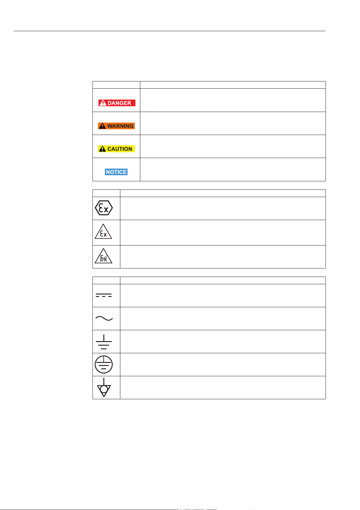
Safety conventions
Type of protection .
Icon Meaning
DANGER!
This symbol alerts you to a dangerous situation. Failure to avoid this situation will result
in serious or fatal injury.
WARNING!
This symbol alerts you to a dangerous situation. Failure to avoid this situation can result
in serious or fatal injury.
CAUTION!
This symbol alerts you to a dangerous situation. Failure to avoid this situation can result
in minor or medium injury.
NOTICE!
This symbol contains information on procedures and other facts which do not result in
personal injury.
Icon Meaning
Device certified for use in explosion hazardous area
If the device has this symbol embossed on its name plate it can be installed in an explosion
hazardous area in accordance with the specifications in the certificate or in a safe area.
Explosion hazardous area
Symbol used in drawings to indicate explosion hazardous areas. Devices located in and wiring
entering areas with the designation “explosion hazardous areas” must conform with the stated type
of protection.
Safe area (non-explosion hazardous area)
Symbol used in drawings to indicate, if necessary, non-explosion hazardous areas. Devices located
in safe areas still require a certificate if their outputs run into explosion hazardous areas.
Electrical symbols .
Icon Meaning
Direct voltage
A terminal to which or from which a direct current or voltage may be applied or supplied.
Alternating voltage
A terminal to which or from which an alternating (sine-wave) current or voltage may be applied or
supplied.
Grounded terminal
A grounded terminal, which as far as the operator is concerned, is already grounded by means of an
earth grounding system.
Protective grounding (earth) terminal
A terminal which must be connected to earth ground prior to making any other connection to the
equipment.
Equipotential connection (earth bonding)
A connection made to the plant grounding system which may be of type e.g. neutral star or
equipotential line according to national or company practice.
8 Endress+Hauser
Page 9
WirelessHART Fieldgate SWG70 Identification
1
2
4
3
x
Made in Germany
CH-4153 Reinach, Switzerland
Order code:
SWG70-1056/0
Ser. no.:
60011009001
Ext. ord. cd.:
SWG70-BG3
WirelessHART Fieldgate SWG70
U:
P:
Ta:
Dev.Rev.:
CMIIT-ID:
FCC-ID:
Contains:
IC-ID:
5853A-M2140
SJC-M2140
2.4 GHz
Dat./Insp.:
2015-07-06
XA00C01S
II 3 G Ex nA nC IIC T4 Gc
НАНИО “ЦСВЭ”
No.: TC RU C-CH.ГБ05.В.00043
2ExnAIIT4 X
DC 20...30 V
< 5 W
-20 °C...+60 °C
R
202-SMD11
0976
IP 66 / IP 67 / NEMA 4
MAC:
DD-DD-BE-DD-DD-BB
FW:
1
2011DJ5310
Anatel ID: HHHHFF-AAAA
FW:
HW:
01.00.01
01.00.00
Order code:
Ser. no.:
Ext. ord. cd.:
2 Identification
2.1 Unpacking
2.1.1 Visual inspection
During unpacking:
• Check the packing materials for signs of transportation damage.
• Remove the packaging material with care, so as not to damage the Fieldgate.
• Store the original packing material, in case the Fieldgate must be shipped again.
• Keep the documentation supplied with the Fieldgate in a safe place.
• Keep the accompanying documents.
2.1.2 Scope of delivery
Please check that the delivery is complete and free of defects before starting installation.
The scope of delivery comprises the following parts:
• WirelessHART Fieldgate SWG70
•Antenna
• Short instructions
• Depending upon order, FieldCare Device Setup DVD
2.1.3 Storage and transport
Always store and transport the device in the original packaging.
Always store the device in a clean, dry environment.
Keep within the permitted storage temperature range. See the Technical Information
document for "WirelessHART Fieldgate SWG70" (TI00027S).
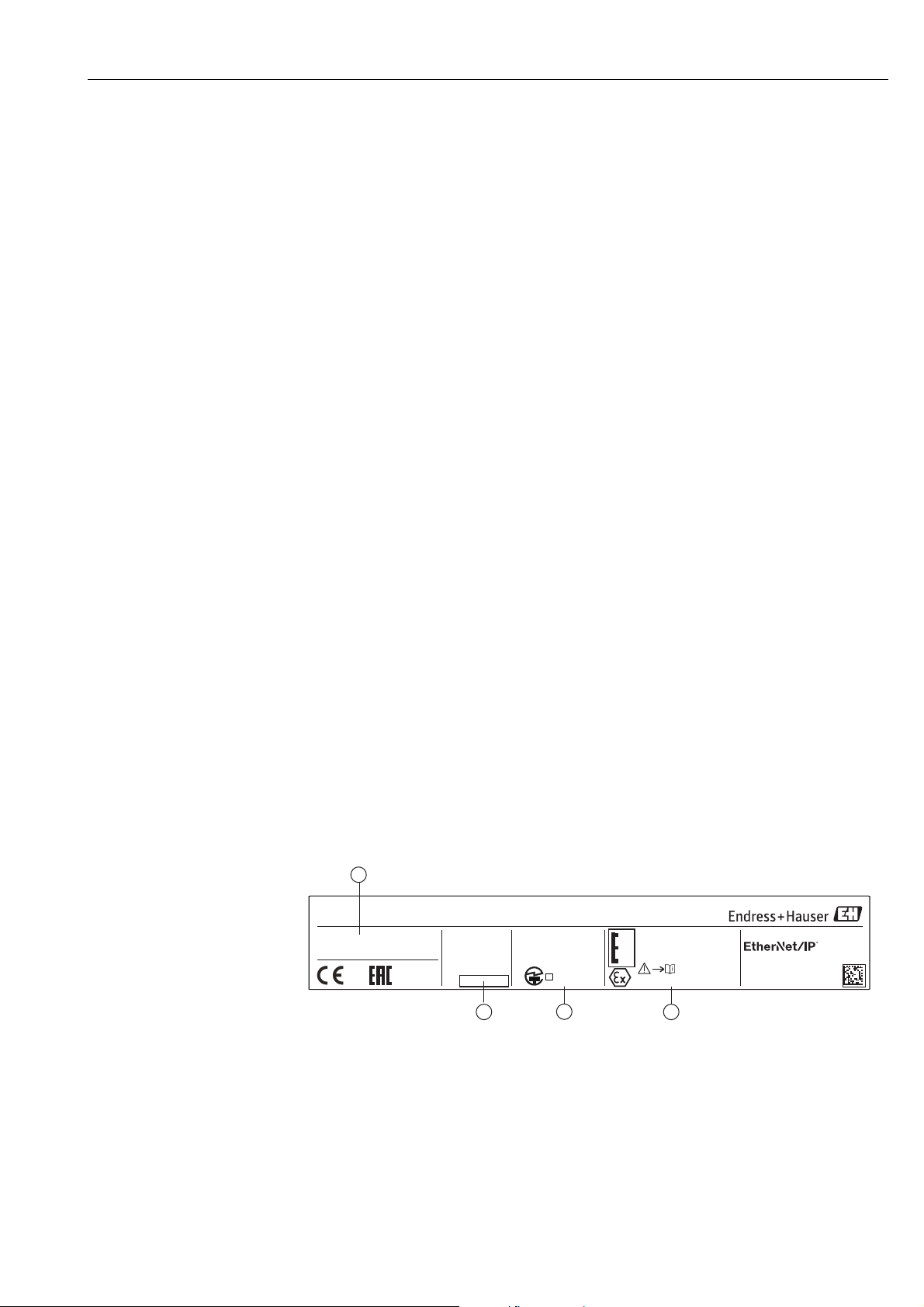
2.2 Nameplate
The device designation together with other information can be found on the nameplate
affixed to the front of the Fieldgate.
Fig. 2-1: Nameplate (example)
Endress+Hauser 9
1 Order number and serial number
2 Type of protection, if any
3 Telecommunication compliance
4 Version information
Page 10

Identification WirelessHART Fieldgate SWG70
2.3 Ordering information
Detailed information about the product structure is available:
• On the Endress+Hauser website: www.endress.com/SWG70
• From your Endress+Hauser Sales Center: www.addresses.endress.com
10 Endress+Hauser
Page 11
WirelessHART Fieldgate SWG70 Function and system design
3 Function and system design
3.1 WirelessHART protocol
The HART protocol has until now used the wired 4–20 mA loop with a superimposed digital
signal as physical layer.
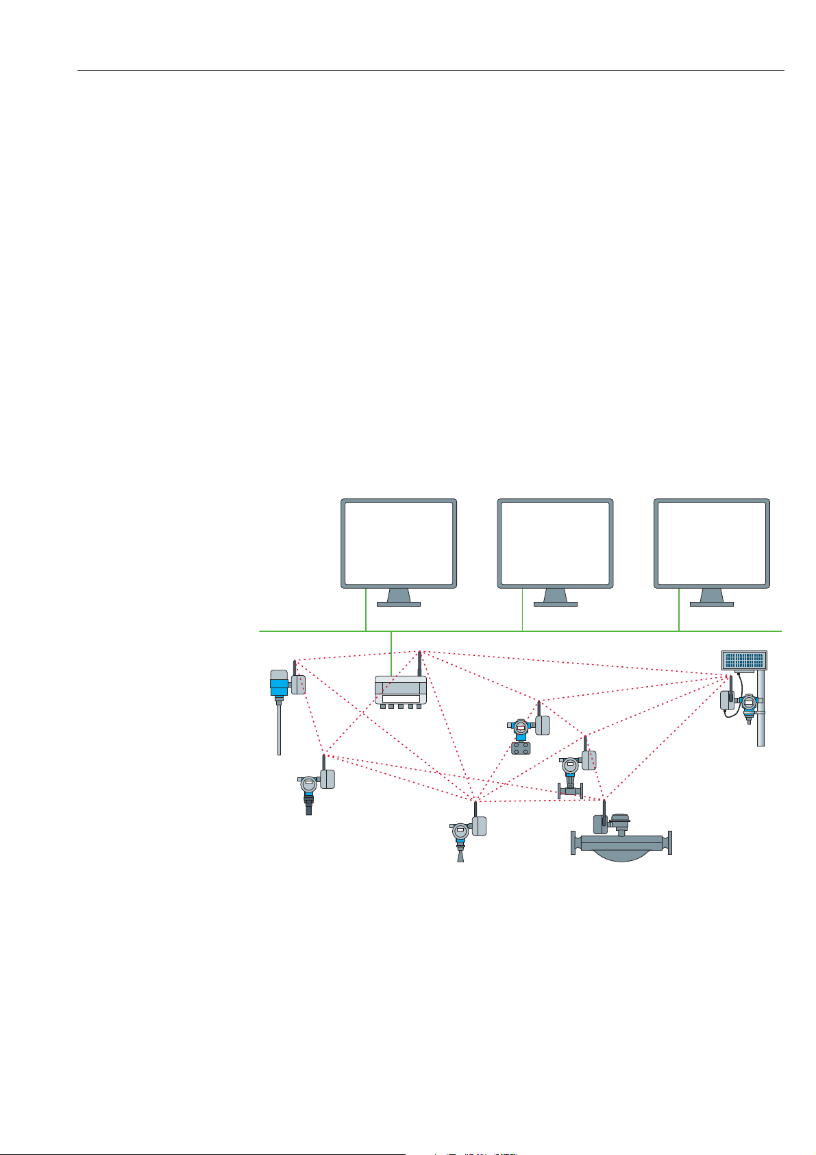
WirelessHART enables the wireless transmission of HART data. To be employable worldwide, WirelessHART utilizes the 2.4 GHz Band (IEEE 802.15.4 wireless network) as physical
layer. The WirelessHART devices form a mesh network in which every device is not just a
measurement point, but also a repeater. This results in a wider range for the whole network
as well as increased reliability through redundant communication paths.
The network may comprise three types of device:
• WirelessHART gateway (Fieldgate SWG70)
• WirelessHART field devices
• WirelessHART Adapters (SWA70): either connected to 4–20 mA/HART devices or acting
as repeaters.
The WirelessHART network is built up, organized and maintained by the Fieldgate, which
also takes care for connection to different HOST systems through different bus interfaces.
1
Ethernet
4
4
3
2
4
4
4
4
Fig. 3-1: WirelessHART network
1 Host applications
2Ethernet
3 WirelessHART Fieldgate
4 Field devices with wireless
Endress+Hauser 11
Page 12
Function and system design WirelessHART Fieldgate SWG70
1
2
4
5
3
3.2 WirelessHART network
Fieldgate SWG70 is the master device in the WirelessHART network. Acting as network
manager, it recognizes other devices wanting to join the network. It makes contact with each
in turn and initiates the procedures required for them to join. The network organizes itself
without any intervention on the part of the user. Fieldgate SWG70 also acts as security manager and collects the data sent by the network participants, converting it into a form which
can be used by other systems connected to it.
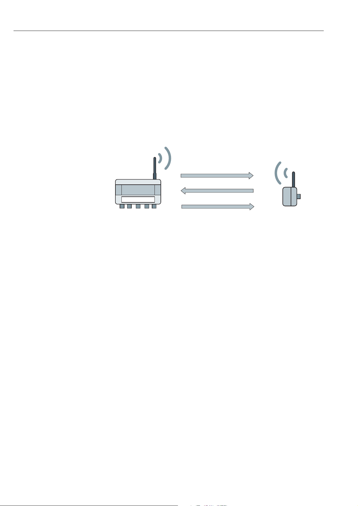
3.2.1 Network management
In its role as network manager, Fieldgate SWG70 organizes the wireless communication
between the WirelessHART field devices.
Fig. 3-2: Network management
1Step 1: Advertising
2Step 2: Join Request
3 Step 3: Authorization, Session & Network Keys,
Scheduling and Routing
4 WirelessHART gateway (Fieldgate SWG70)
5 WirelessHART device or adapter
After the Fieldgate has started up the network, devices can join. To this end, it first sends out
a call for devices to join the network. Then, the device sends a join request to announce its
wish to join the network. If the WirelessHART field device can identify itself with the same
network ID and join key as stored in the WirelessHART Fieldgate, the field device is authorized to join the network. Otherwise, the field device will be rejected.
In the next step, the WirelessHART Fieldgate sends session and network keys as well as
scheduling and routing information to the field device. The field device is told how to participate in the network and receives various information from the WirelessHART Fieldgate:
• Number and identity of neighboring WirelessHART field devices,
• When to send messages and which channels to use,
• When to repeat messages for other WirelessHART field devices,
• The optimal communication path for messages as well as alternative communication
paths in case of failure.
During this process, the WirelessHART device or adapter may also apply to send messages
in certain intervals and ask the network manager for the appropriate resources. The network
manager then takes care that these resources are available. For example, the network manager informs other WirelessHART field devices when to repeat messages.
3.2.2 WirelessHART security management
Fieldgate SWG70 also acts as security manager. To make communication safe, all messages
are encrypted with industry-standard AES-128 block ciphers with symmetric keys. Therefore, messages are unreadable for external listeners. The encryption keys are distributed by
the security manager.
The Join Key is used to join the network. Subsequently, the Join Key is automatically
exchanged against the Session Key and the Network Key, i.e. two new additional keys.
12 Endress+Hauser
Page 13
WirelessHART Fieldgate SWG70 Function and system design
1
2
3
4
5
WirelessHART-Gateway
I/O card 1
I/O card 2
Channel 0
WirelessHART Field device
WirelessHART Adapter
Channel 0
Channel 1
WirelessHART Field device1
WirelessHART Field device2
WirelessHART Field device3
Network structure
1
2
3
4
5
5
5
Instrument list I/O structure
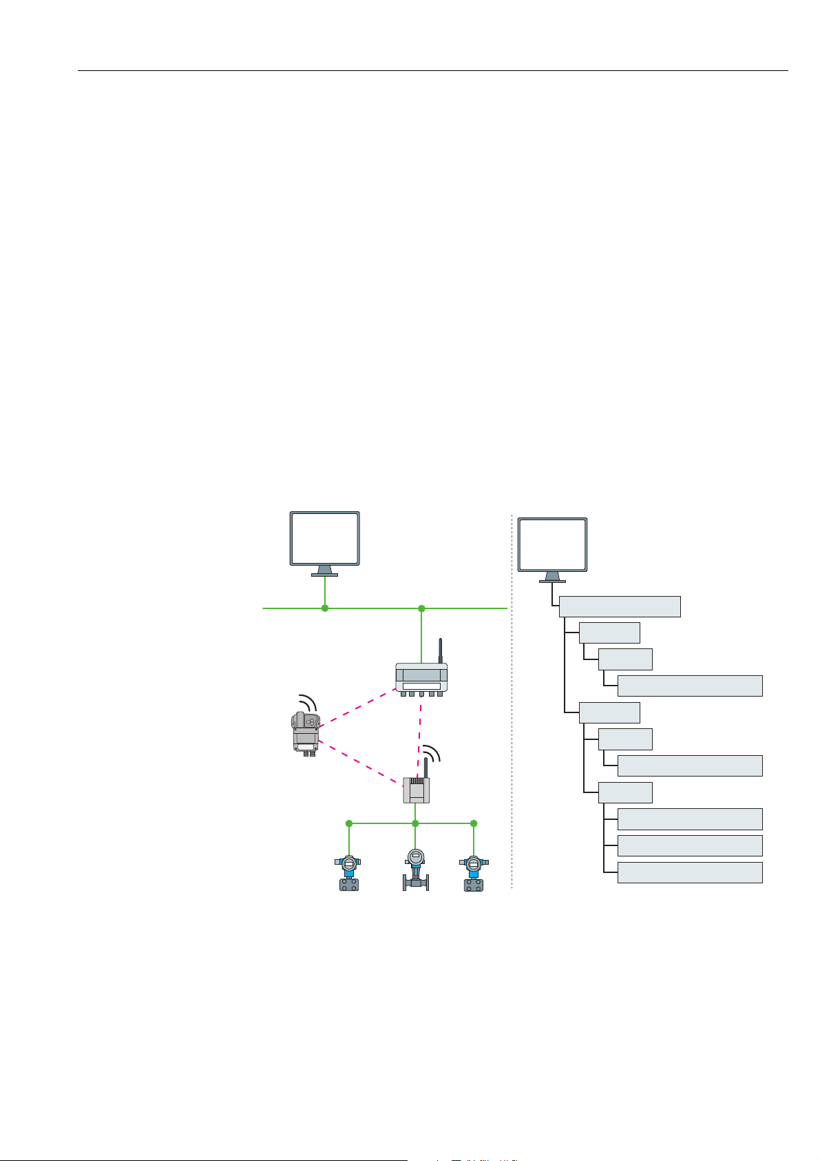
3.3 Connecting to HART-compatible host systems
Fieldgate SWG70 also makes wireless communication accessible to HART-capable host systems via its Ethernet interface or serial interfaces (RS-485) and the following functions.
Depending on the version ordered, Fieldgate SWG70 can also be integrated into Modbus,
OPC or Ethernet/IP host systems.
3.3.1 Instrument list
The WirelessHART devices in the network are made available to the host systems via an
instrument list. This list contains one or more I/O cards. Every I/O card has one or more
channels. Up to 6 field devices can be connected in multidrop mode to each channel. See
Figure 3-3 on page 13. The list itself can be up and downloaded. See Chapter 10.1 "Instrument List" on page 62.
Fieldgate SWG70 assigns a virtual I/O card to each WirelessHART device. The I/O cards are
assigned to the WirelessHART devices in the order in which they join the network. New
WirelessHART devices in the network are assigned to the next available I/O card, which is
added to the end of the instrument list (First-in-First-Out principle).
Within an I/O card, the WirelessHART device itself as well as status information is assigned
to Channel 0. If the WirelessHART device is an adapter, all field devices connected to it are
assigned to channel 1 (multi-drop mode). The list of the connected field devices is also called
sub-device list.
If a WirelessHART device loses communication to the Fieldgate, it stays assigned to the I/O
card initially allocated to it. When communication is established again, the device thus has
the same position in the instrument list that it had before.
The same principle applies to the field devices connected to the WirelessHART Adapter
(SWA70). When communication to the Fieldgate is lost, the long tags of the filed devices are
Fig. 3-3: Instrument list
stored. After communication has been established again, the field devices regain their previous position in the instrument list.
Endress+Hauser 13
Page 14

Function and system design WirelessHART Fieldgate SWG70
3.3.2 Cache
The WirelessHART Fieldgate stores information received over the WirelessHART network
and makes it available to the host for further processing. This ensures that information is
available immediately for the host system without having to send a request to the device and
wait for the response. The following commands and answers to requests are cached in the
Fieldgate.
Information cached in the
WirelessHART Fieldgate
Cache HART Command Description
Static: cached upon
read
Static: cached upon
read & write
confirmation
Dynamic: cached on
publication only
0, 11, 21 Read unique identifier (associated with tag or long tag)
12, (17) Read (Write) Message
13, (18) Read (Write) Short Tag, Descriptor, Date
20, (22) Read (Write) Long Tag
50 (51) Read (Write) Dynamic Variable Assignments
1 Read Primary Variable
2 Read Current and Percentage
3 Read All Variables
9 Read Device Variables and Status
33 Read Device Variables
38 Read Additional Device Status
48 Reset Configuration Change Counter
93 Read Trend
Each listed command has its own cache memory. Static commands are stored in the cache
upon the first request. Dynamic variables are stored each time a field device sends a burst
message so that up-to-date values are available at all times.
With the exception of write commands 17, 18, 22 and 51, when the WirelessHART
Fieldgate receives a request from a host system which is embedded in Command 77, the
response is sent immediately (provided that the response is available in the cache).
Long Tag Emulation WirelessHART uses the long tag for addressing devices. Not every HART device supports
long tags, for example, older HART devices with HART Protocol Version 5 or less, do not support long tag addressing.
If a HART 5.0 device is connected to a WirelessHART Adapter (SWA70), the WirelessHART
Fieldgate emulates the long tag using the "Message" field. When a host system addresses a
HART 5 device, the emulation translates Command 20(22) directly into Command 12 (17)
which the HART 5 understands. The response is stored in the Fieldgate cache for CMD
12(17) and for CMD 20(22).
14 Endress+Hauser
Page 15

WirelessHART Fieldgate SWG70 Installation
4Installation
NOTICE!
• It is recommended that Fieldgate SWG70, adapters and devices be setup on the test bench
and the network be tested before the components are installed in the field.
4.1 Mounting considerations
4.1.1 Positioning the Fieldgate
Install the Fieldgate before installing other WirelessHART devices. This way you can check
for proper operation of new devices as they are installed. Nevertheless, consider the location
of future WirelessHART devices that will be routed through the Fieldgate to ensure good
connectivity.
Guidelines for Planning a
WirelessHART Network
• Mark the positions of the various measuring points on a scale overview of the plant. It is
important that the overview shows likely obstacles to the propagation of the radio waves.
• Make sure that a minimum of 2 other WirelessHART devices are well within the antenna
range of the device. If necessary, consider using an adapter as an additional stand-alone
repeater. Please refer to the following section for more information about the antenna
properties.
• Where a lot of metal, grids or walls prevent a device from being in line-of-sight of its
nearest neighbor, the maximum distance between two devices is 30 m. Install wireless
devices at least 1m above the ground or the floor.
• Where there are fewer structural elements and one or more neighbors are in direct lineof- sight, the maximum distance between two devices for planning purposes is 200 m. In
this case, install wireless devices at least 3m above the ground or the floor.
• Consider moving objects that could affect the device's antenna range.
• Make sure that the device's antenna is aligned vertically.
• If possible, position the Fieldgate at or near the center of the network - it should be in
contact with at least 20% of the devices in the network.
• Do not position WirelessHART devices directly below or above each other as they will be
outside each other's antenna range. See Chapter 4.1.3 "Examples of good and poor
positioning" on page 17.
• If possible, do not position the device next to metal surfaces, pipes or walls containing
metal (minimum distance: 6 centimeters). There should be as little metal around the
device as possible.
• Do not position other 2.4 GHz devices like cordless phone bases or WLAN routers near
WirelessHART devices. Wireless technologies used in an industrial environment must be
able to coexist without disrupting each other. If multiple networks operate in one facility,
wireless frequency management may be required.
Endress+Hauser 15
Page 16
Installation WirelessHART Fieldgate SWG70
1
2
2
1
α
α
α
α
100%
100%
50%50%
50%50%
0%
0%
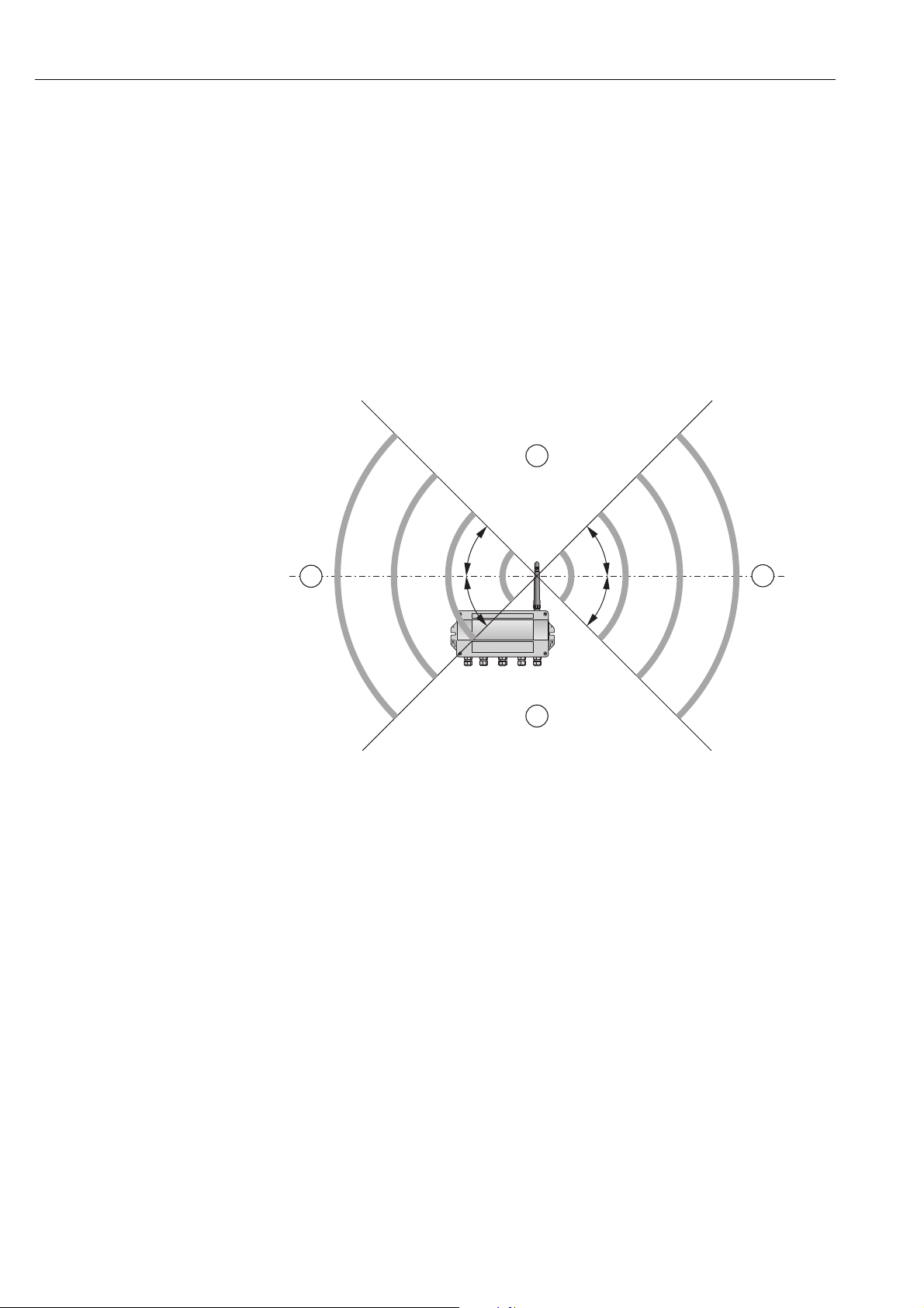
4.1.2 Antenna range
The antenna supplied is an omni-directional dipole antenna.
A schematic representation of the wave propagation is provided in the following graphic.
If the antenna is pointed upwards, the signal is emitted horizontally. The transmission and
reception quality decreases by up to 50% as of an angle of approx. 39°. Almost no signal will
be radiated directly above and below the antenna.
We therefore recommend that you mount the wireless devices on one plane where possible.
If you must mount the wireless devices on very different planes, we recommend you use a
remote antenna. See Chapter 4.2 "Mounting the antenna" on page 17. Different coverage is
achieved with a remote antenna. For the associated requirements, please see the Technical
Information document for "WirelessHART Fieldgate SWG70" (TI00027S).
Fig. 4-1: Wave propagation, schematic representation (alpha = approx. 39°)
1 No signal above and below 2 Stronger signal sideways
16 Endress+Hauser
Page 17
WirelessHART Fieldgate SWG70 Installation
PWR
COM
FLT
-
Height
Distance
/
Height
Distance
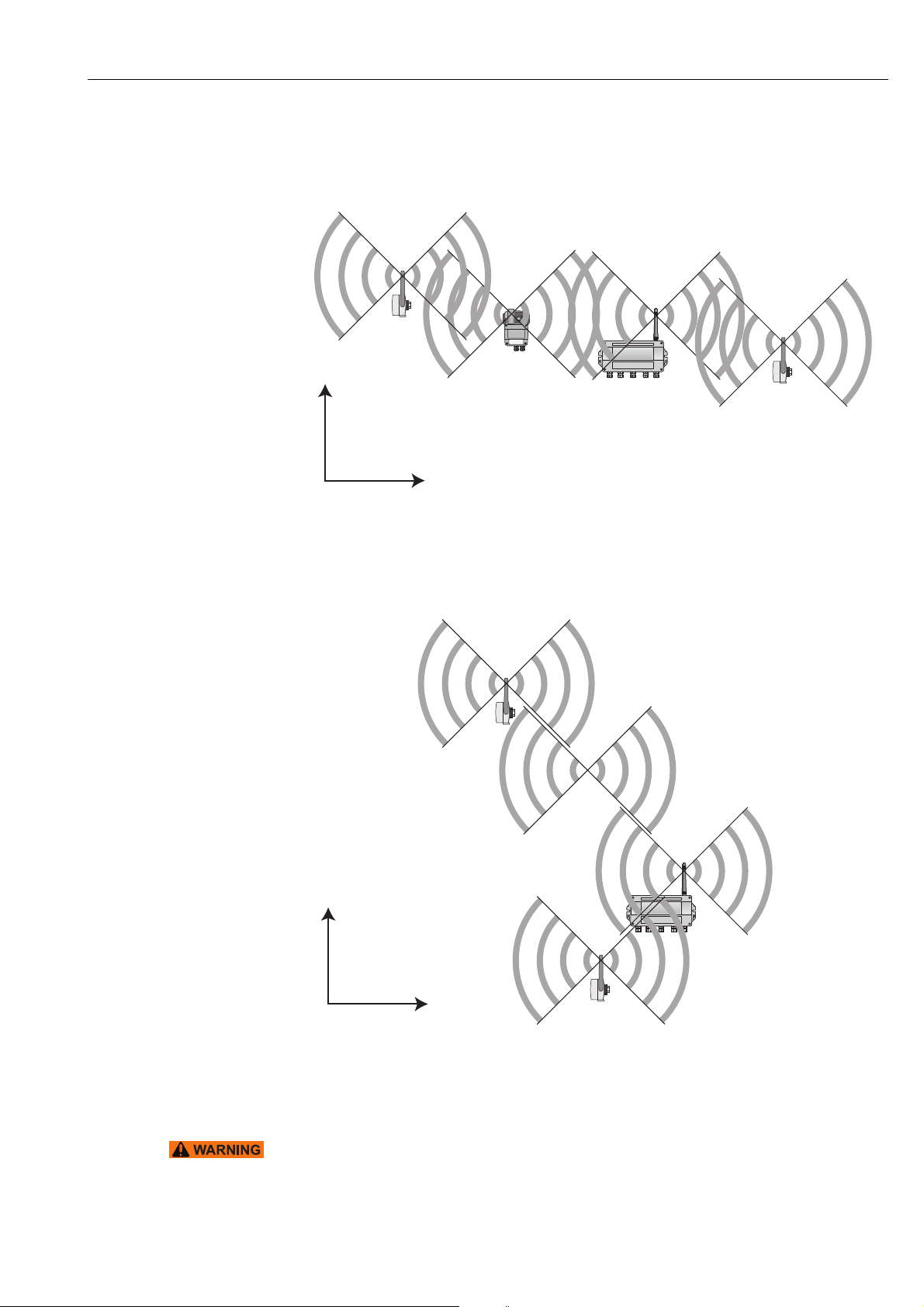
4.1.3 Examples of good and poor positioning
The positioning is good when the network participants are within the antenna range:
Fig. 4-2: Example of good positioning
The positioning is poor when neighbors are not in the antenna range or within the weaker
signal zone of the antenna:
Fig. 4-3: Example of poor positioning
Endress+Hauser 17
4.2 Mounting the antenna
WARNING!
• If Fieldgate SWG70 is installed in a hazardous area Zone 2, you may only connect or
disconnect the antenna and cables in the absence of any potentially explosive atmosphere
or if the Fieldgate is not connected to the power supply.
Page 18
Installation WirelessHART Fieldgate SWG70
2
1
6
7
53 4
NOTICE!
• Use only the antenna supplied or a remote antenna that meets the requirements. For
the associated requirements, please see the Technical Information document for
"WirelessHART Fieldgate SWG70" (TI00027S).
4.2.1 Mounting the antenna supplied
1. Switch off the power supply to the Fieldgate.
2. Firmly screw the antenna to the device's antenna terminal.
See Figure 5-1 on page 20, Item 6.
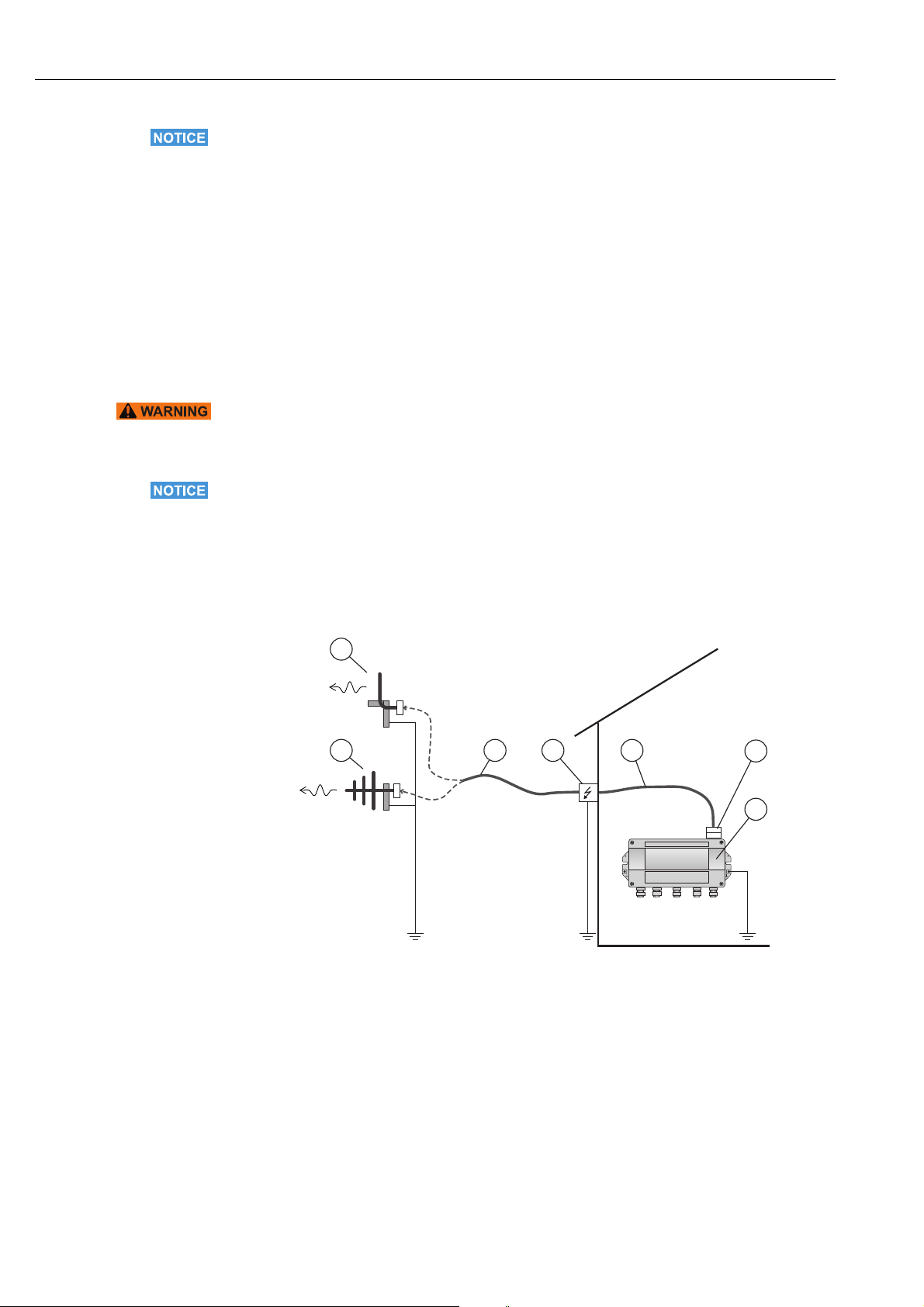
4.2.2 Connecting a remote antenna
WARNING!
• Outdoor installations can be subject to lightning strikes. Install a surge arrester to protect
the installation against transients or damage caused by lightning strikes.
NOTICE!
• Only use antennas, cables and surge arresters that are listed in the Technical Information
document "WirelessHART-Fieldgate SWG70" (TI00027S).
• Ensure adequate strain relief for the cables.
• Pay attention to the bending radii of the cables. Do not drop below the permitted bending
radii.
Fig. 4-4: Installation of an remote antenna
1 Omnidirectional antenna
2 Directional antenna
3 Coaxial cable with connector
4Surge arrester
5 Coaxial cable with connector
6 Coaxial adapter
7 Fieldgate SWG70
1. Switch off the supply voltage to the Fieldgate.
2. Install the antenna where it is within the antenna range of other WirelessHART
devices. See Chapter 4.1.3 "Examples of good and poor positioning" on page 17.
18 Endress+Hauser
Page 19
WirelessHART Fieldgate SWG70 Installation
2
1 1
2
3. Mount the surge arrester indoors. The coaxial cable between the surge arrester and
Fieldgate may only be routed indoors.
4. Connect the antenna to the surge arrester using a coaxial cable.
5. Connect the antenna, the surge arrester and the Fieldgate to the protective grounding
as illustrated in Figure Fig. 4-4.
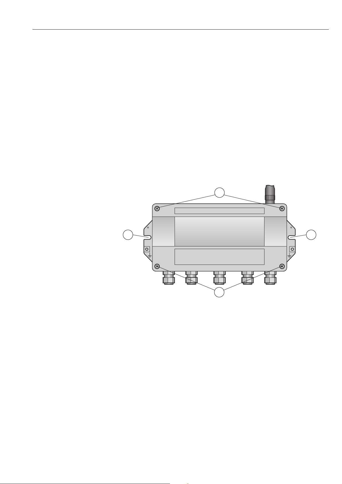
4.3 Mounting the Fieldgate
In addition to fulfilling the conditions for good wireless communication, the mounting location should be well accessible for mounting and electrical installation. Make sure that there
is enough space to open the housing cover and to access the terminals, switches, and cable
glands. Choose a mounting location that meets the climatic limits specified and radio
requirements in the technical data.
Required tools:
• 2 screws (M6)
• Drill
• Screwdriver
Fig. 4-5: Mounting holes and housing screws
1 Mounting holes 2 Housing screws
Mounting the Fieldgate 1. Drill 2 holes in the mounting surface so that they match the holes of the housing
(centers 240 mm to 250 mm apart). See the Technical Information document for
"WirelessHART Fieldgate SWG70" (TI00027S).
2. Screw the device to the mounting surface.
Endress+Hauser 19
Page 20
Electrical Installation WirelessHART Fieldgate SWG70
5
1
6
1
2 3 4
7
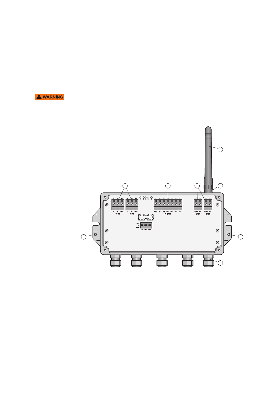
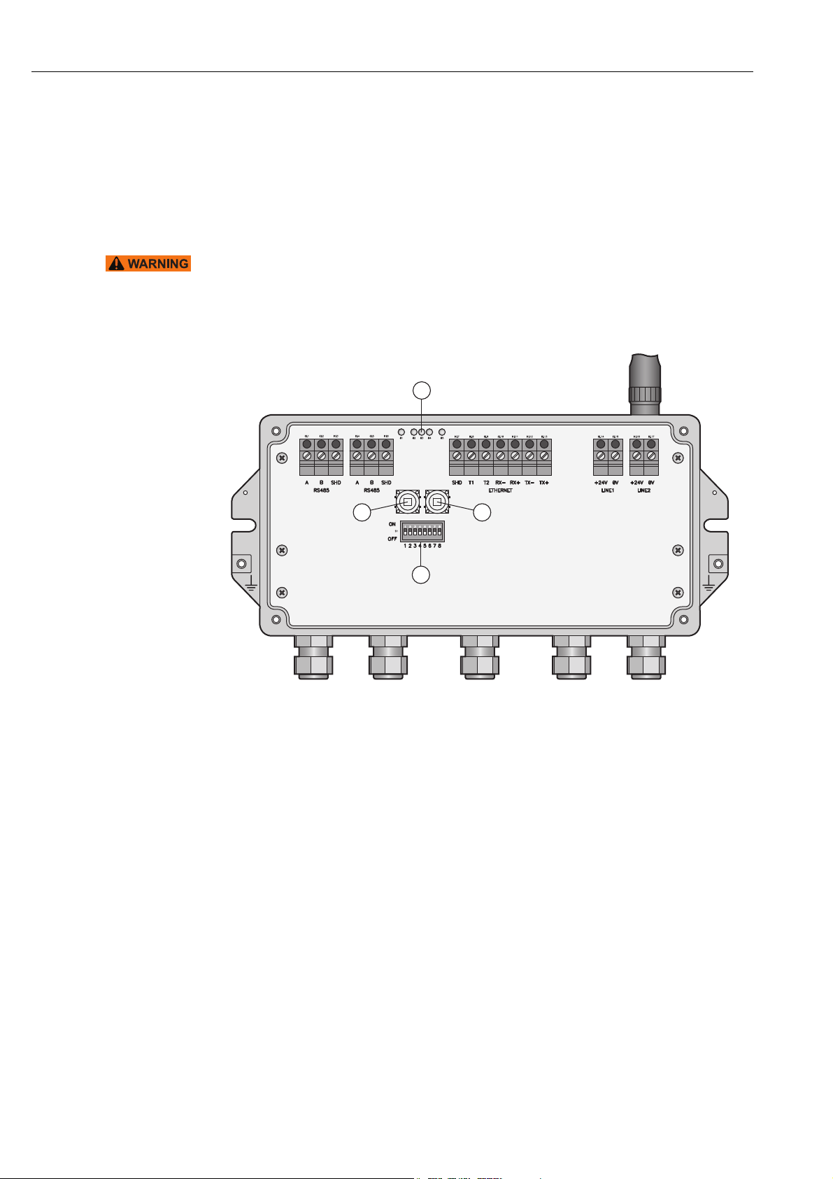
5 Electrical Installation
5.1 Connections and interfaces
The connections and interfaces are only accessible with an open enclosure. In the case of the
DIP switches, the user has the choice of using the switch settings, or overriding the settings
by software. See Chapter 8 "Fieldgate configuration" on page 42.
WARNING!
• If Fieldgate SWG70 is installed in a hazardous area Zone 2, you may only connect or
disconnect the antenna and cables in the absence of any potentially explosive atmosphere
or if the Fieldgate is not connected to the power supply.
Fig. 5-1: Connections and interfaces
1Grounding terminal
2 RS-485 interfaces, duplicated terminal block for
daisy-chain capability
3 Ethernet interface
4 Power supply connections (redundant)
5 Antenna
6 Antenna terminal
7 Cable glands
20 Endress+Hauser
Page 21
WirelessHART Fieldgate SWG70 Electrical Installation
1
2
KL14
KL15 KL16
KL17
+24V +24V0V 0V
LINE1
LINE2
+24V +24V
0V 0V
LINE1 LINE2
A
B
SHD
RS485
T1
T2
RX–
RX+
TX–
TX+
ON
OFF
SHD
A
B
SHD
RS485
ETHERNET
3 3
5.2 Connecting to power supply and grounding
There are two 24 VDC power supply terminal blocks located inside Fieldgate SWG70, allowing for redundant power supply. Open the housing cover to access the terminal blocks.
NOTICE!
• Ensure adequate strain relief for the cables.
• Pay attention to the bending radii of the cables. Do not drop below the permitted bending
radii.
Connecting to 24 VDC
power supply and
grounding
Fig. 5-2: Power supply
1 First power supply connection
3Grounding terminals
2 Second (redundant) power supply connection
Fieldgate SWG70 must be connected to a 24 VDC power supply. For details, see the
Technical Information document for "WirelessHART Fieldgate SWG70" (TI00027S).
DANGER!
Risk of electric shock if the wrong power unit is used.
• Always use a SELV/PELV power unit to guarantee electrical safety.
1. Switch off the power supply.
2. Connect the protective ground to one of the two ground terminals.
3. Unscrew the 4 screws of the housing cover and remove the housing cover. See
Figure 4-5 on page 19.
4. Route the 24 VDC power cable through the second cable gland from right.
The permissible cable diameter lies between 6 mm and 10 mm.
5. Connect the 24 VDC power cable to the first power supply connection "Line 1" observing
polarity. See Figure 5-1 on page 20.
6. If you want to connect a redundant power supply (optional), route the second 24 VDC
power cable through the cable gland on the far right of the housing.
7. Connect the second power cable to the second power supply connection "Line 2"
observing polarity.
8. Switch on the power supply. The green power LED should light up immediately.
9. Tighten the cable gland with appropriate torque. See Chapter 5.5 "Cable glands and
housing cover" on page 25.
Endress+Hauser 21
Page 22
Electrical Installation WirelessHART Fieldgate SWG70
KL7 KL8 KL9 KL10
+24V +24V
0V 0V
LINE1 LINE2
A
B
SHD
RS485
T1
T2
RX–
RX+
TX–
TX+
ON
OFF
SHD
A
B
SHD
RS485
ETHERNET
T1 T2 RX– RX+ TX– TX+SHD
ETHERNET
KL11 KL12 KL13
5.3 Connecting to Ethernet
WARNING!
• If Fieldgate SWG70 is installed in a hazardous area Zone 2, you may only connect or
disconnect the antenna and cables in the absence of any potentially explosive atmosphere
or if the Fieldgate is not connected to the power supply.
NOTICE!
• Keep in mind that an access point of the Ethernet network has to be available. The
maximum length of the cable running from the Fieldgate to the access point is 100 m,
depending on the cable type and communication speed.
• Please note that older computers, hubs, switches or routers might not feature automatic
TX/RX detection. In this case, use a crossover cable.
• Ensure adequate strain relief for the cables.
• Pay attention to the bending radii of the cables. Do not drop below the permitted bending
radii.
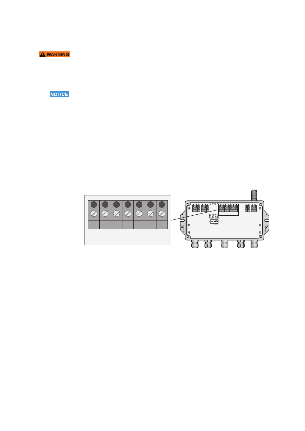
5.3.1 Connecting the "Modbus" or "Modbus + OPC" versions to
Ethernet
The Ethernet cable is connected directly to the Ethernet terminal block in the Fieldgate.
Fig. 5-3: Fieldgate with 5 cable entries and Ethernet terminal block
1. Switch off the power supply.
2. Unscrew the screws of the housing cover and remove the housing cover. See Figure 4-5
on page 19.
3. Route the Ethernet cable through the cable gland in the middle of the Fieldgate
housing. The permissible cable diameter is between 6 mm and 10 mm.
22 Endress+Hauser
Page 23
WirelessHART Fieldgate SWG70 Electrical Installation
123 45 678
KL7 KL8 KL9 KL10
A
B
SHD
RS485
T1
T2
ON
OFF
SHD
A
B
SHD
RS485
ET
T1 T2 RX– RX+ TX– TX+SHD
ETHERNET
KL11 KL12 KL13
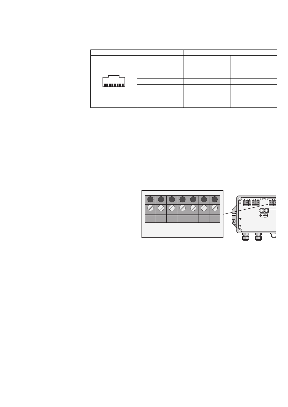
4. Connect the Ethernet cable to the terminal block labeled "Ethernet" according to the
following table.
Computer Fieldgate
Pin Numbering Connector Crossover cable Normal cable
Pin 1 TX+ RX+
Pin 2 TX– RX–
Pin 3 RX+ TX+
Pin 4 T2 T2
Pin 5 T2 T2
Pin 6 RX– TX–
Pin 7 T1 T1
Pin 8 T1 T1
5. Screw the housing cover on the housing.
6. Tighten the cable gland with appropriate torque. See Chapter 5.5 "Cable glands and
housing cover" on page 25.
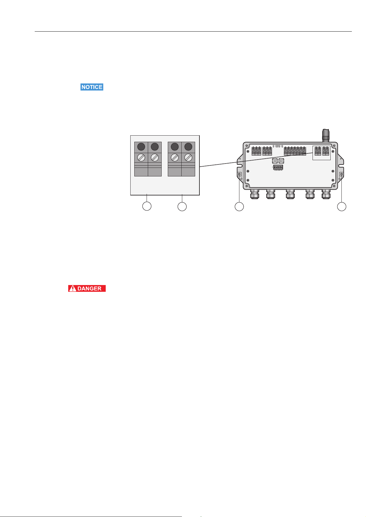
7. Switch on the power supply.
5.3.2 Connecting the "EtherNet/IP" version to Ethernet
The Ethernet cable with a D-coded M12 connector is connected to the M12 socket of the
Fieldgate housing.
Fig. 5-4: Fieldgate with M12 socket in the middle
1 Ethernet terminal block wired internally to M12
socket
2 M12 socket, D-coded for connection to an
Ethernet or Ethernet/IP network
1. Switch off the power supply.
2. Plug the D-coded M12 connector into the Ethernet socket of the Fieldgate. See
Figure 5-4 on page 23.
3. Tighten the coupling nuts on the M12 connector. The Fieldgate is connected to the
Ethernet network.
4. Switch on the power supply.
Endress+Hauser 23
Page 24
Electrical Installation WirelessHART Fieldgate SWG70
3
4
2
1
KL1 KL2 KL3 KL4
+24V +24V
0V 0V
LINE1 LINE2
A
B
SHD
RS485
T1
T2
RX–
RX+
TX–
TX+
ON
OFF
SHD
A
B
SHD
RS485
ETHERNET
KL5 KL6
A B SHD
RS485
A B SHD
RS485
1
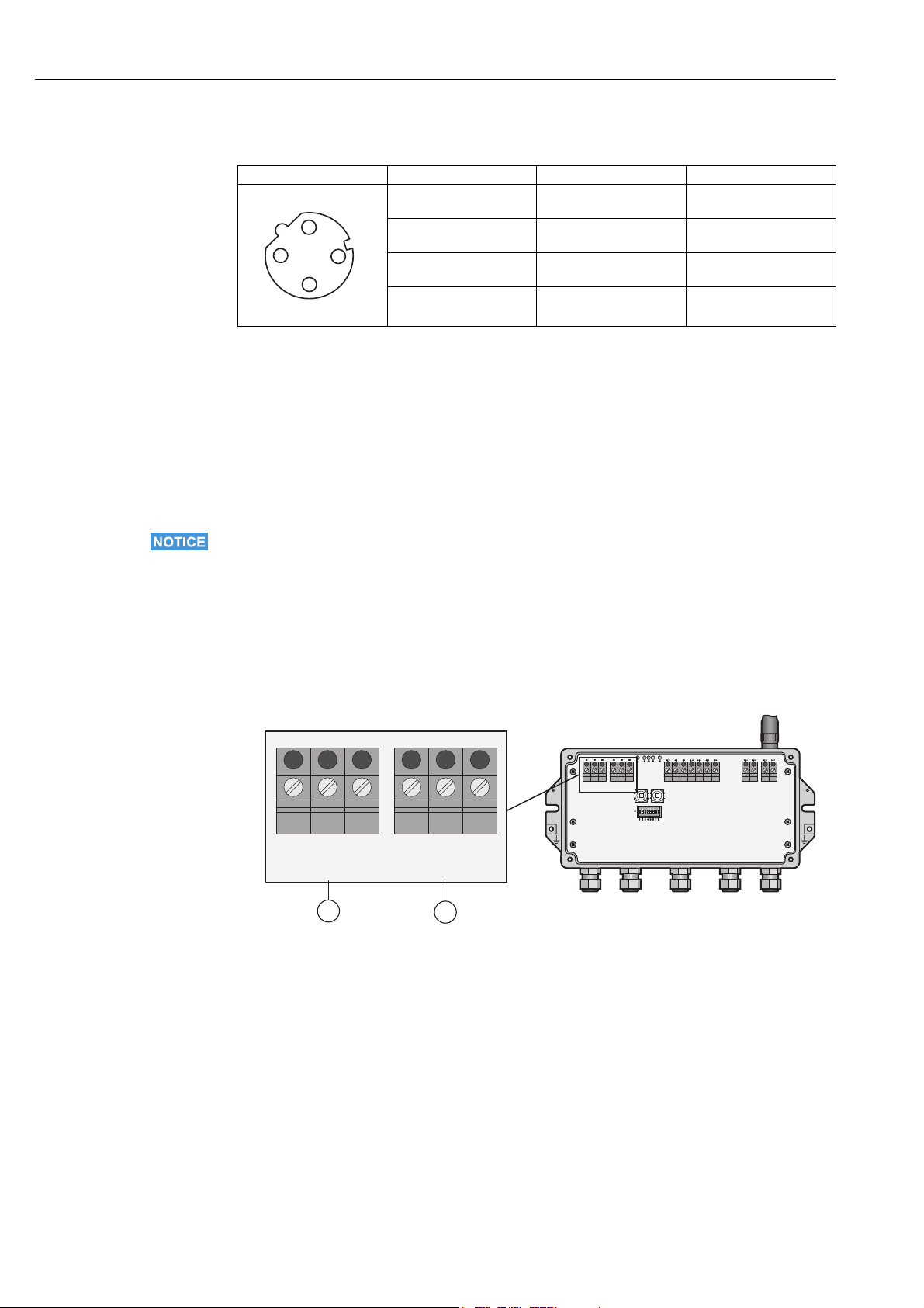
2
Internal wiring The Ethernet socket is wired to the Ethernet terminal block. The internal wiring may not be
modified.
Pin Numbering Connector Signal Internal Wire Colors
Pin 1 TX+ Yellow
.
Pin 2 RX+ White
Pin 3 TX– Orange
Pin 4 RX– Blue
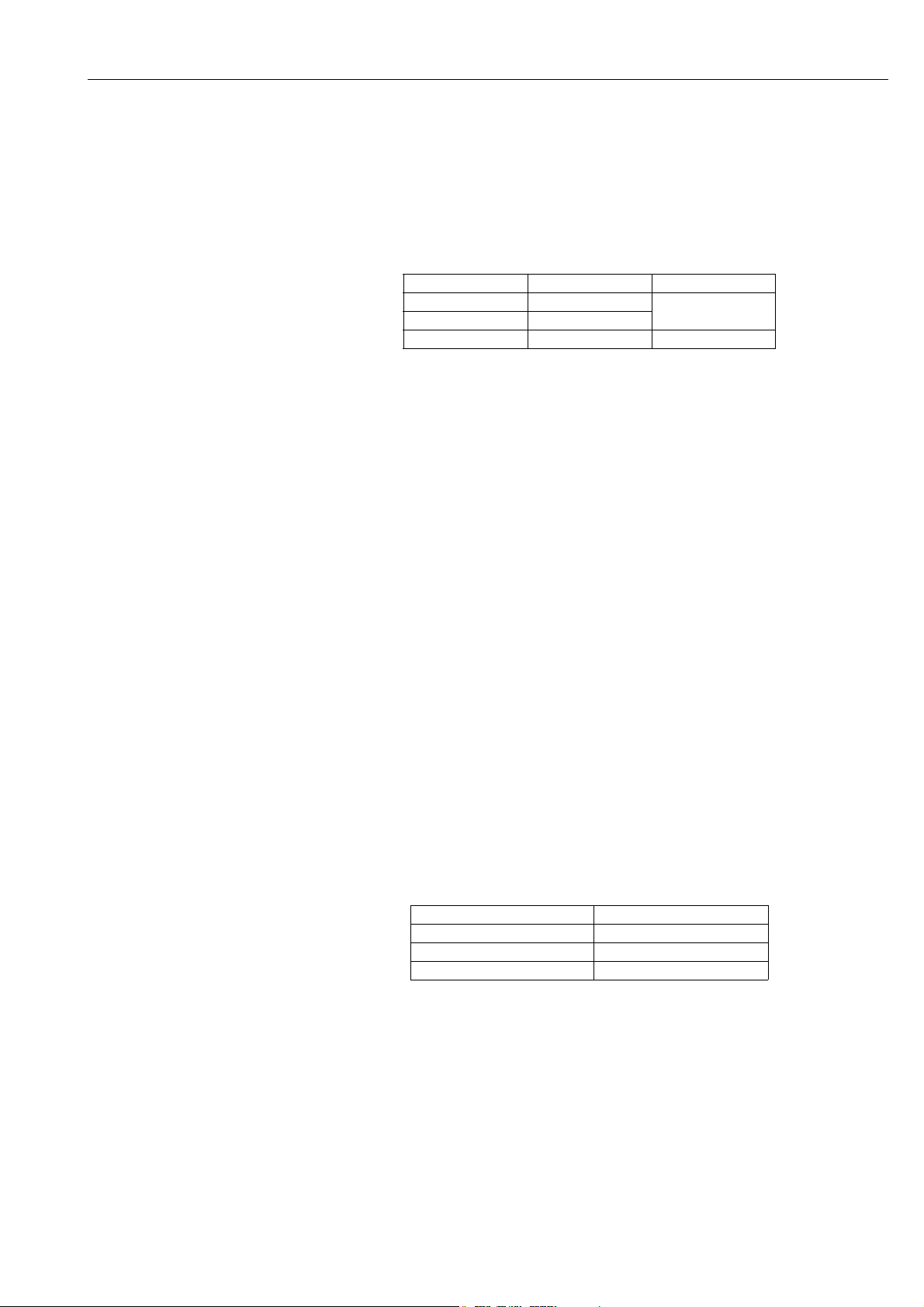
5.4 Connecting to RS-485
Fieldgate SWG70 is equipped with a fully galvanic isolated RS-485 interface. A second
RS-485 terminal block allows several Fieldgates to be connected through a daisy chain.
A terminating resistor is required at each end of the RS-485 cable. If the RS-485 cable is not
routed to other devices (no daisy-chain connection), activate the terminating resistor using
the corresponding DIP switches in the fieldgate. See Chapter 6.1.3 "DIP switches" on page 29.
NOTICE!
• The maximum length of the cable from the Fieldgate is 1200m (at reduced
communication speed).
• Use shielded twisted pair (STP) cables only.
• If the cable shield is grounded, only connect the grounding to one cable end. This avoids
potential equalization currents.
• Ensure adequate strain relief for the cables.
• Pay attention to the bending radii of the cables. Do not drop below the permitted bending
radii.
Fig. 5-5: RS-485 interface
1 First RS-485 connection 2 Second RS-485 connection for daisy chaining
24 Endress+Hauser
Page 25
WirelessHART Fieldgate SWG70 Electrical Installation
Connecting to RS-485 1. Switch off the power supply.
2. Unscrew the screws of the housing cover and remove the housing cover. See Figure 4-5
on page 19.
3. Route the RS-485 cable through the first cable gland from left.
The permissible cable diameter is between 6 mm and 10 mm.
4. Connect the RS-485 cable to the left terminal block labeled "RS-485" as follows (see the
graphic above):
Wire RS-485 cable Fieldgate terminal Remarks
RxD/TxD– (RS-485 A) A RS-485 differential
RxD/TxD+ (RS-485 B) B
Shield SHD Cable shielding
signal
5. For a daisy-chain connection, route the second RS-485 cable through the second cable
gland from left and connect it to the right terminal block labeled "RS-485", see table
above.
6. To activate the RS-485 termination, set DIP switch number 7 to "ON". See Chapter 6.1.3
"DIP switches" on page 29.
7. Screw the housing cover on the housing.
8. Tighten the cable gland with appropriate torque. See Chapter 5.5 "Cable glands and
housing cover" on page 25.
5.5 Cable glands and housing cover
The degree of protection cannot be achieved if the cables and cable glands are not fitted
correctly.
To ensure the IP degree of protection
• all screws of the housing / housing cover must have been tightened with the appropriate
torque,
• only cables of the appropriate size must be used in the cable glands,
• all cable glands must be tightened with the appropriate torque,
• all seals must be undamaged and fitted correctly,
• all empty cable glands must be sealed with appropriate plugs.
The tightening torques of cable glands depend on what type of cable is used and must therefore be determined by the user. The cap nuts must be securely tightened. Tightening the cap
nuts too tight can have a negative effect on the protection class. The following figures can
be taken as rough guides.
Type of cable gland Approx. installation torque
Plastic 2.5 Nm
Nickel-plated brass 4.1 Nm
Stainless steel 4.1 Nm
The Fieldgate housing cover must be tightened with a torque of 2.5 Nm.
Endress+Hauser 25
Page 26
Operation WirelessHART Fieldgate SWG70
1
2 3
4
6Operation
6.1 Operating and display elements
Inside the fieldgate housing there are LED indicators, DIP switches and reset buttons. The
controls and indicators are accessible with open enclosure.
WARNING!
• If Fieldgate SWG70 is installed in a hazardous area Zone 2, you may only operate the DIP
switches and the keys and only connect or disconnect the cables in the absence of any
potentially explosive atmosphere or if the Fieldgate is not connected to the power supply.
1LEDs
2Button P1
Fig. 6-1: Operating and display elements
3Button P2
4 DIP switches
26 Endress+Hauser
Page 27
WirelessHART Fieldgate SWG70 Operation
+24V +24V0V 0V
LINE1 LINE2
A
B
SHD
RS485
T1
T2
RX–
RX+
TX–
TX+
ON
OFF
SHD
A
B
SHD
RS485
ETHERNET
1
2
3
4
5
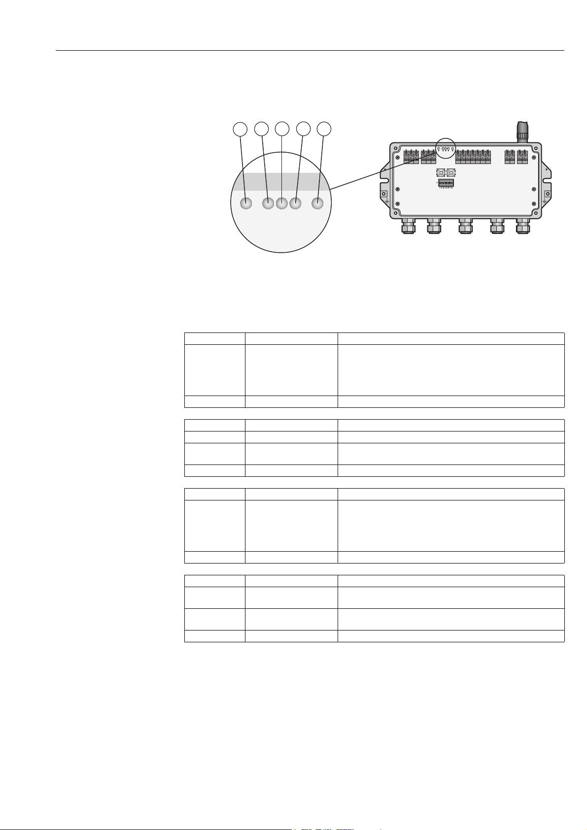
6.1.1 LEDs
Five LEDs indicate the status of Fieldgate SWG70.
Fig. 6-2: LED indicators
Yellow LED: RS-485
communication status
Green LED: Power supply
and operation status
Yellow LED: WirelessHART
communication status
1 Yellow LED: RS-485 communication status
2 Green LED: Power supply
4 Red LED: Device status
5Yellow LED: Ethernet communication status
3 Yellow LED: WirelessHART communication status
Mode Status Meaning
Flashes – Flashes briefly whenever a valid message is received by the
Fieldgate on the RS-485 communication line.
– The LED does not flash if the message is not addressed to the
Fieldgate or if a communication error was detected within the
message.
Off – Currently no communication on the RS-485 line.
Mode Status Meaning
On OK Fieldgate SWG70 is powered up and running
Flashes Not ready On power-up, indicates that the Fieldgate application is running
but the Fieldgate is not yet ready to answer HART commands.
Off No power The power supply is not connected/Fieldgate is not ready.
Mode Status Meaning
Flashes – Flashes shortly whenever a valid WirelessHART message is
received by the Fieldgate on the WirelessHART communication
interface.
– Messages include simple commands but not published bursts
and event notifications.
Off – Currently no communication on the WirelessHART interface.
Red LED: Device status
Mode Status Meaning
On Hardware fault Fieldgate has detected a hardware fault that makes normal
operation impossible.
Flashes Recovering from hardware
fault.
The Fieldgate application is trying to recover from the fault (not
possible for all faults).
Off No hardware fault –
Endress+Hauser 27
Page 28
Operation WirelessHART Fieldgate SWG70
+24V +24V
0V 0V
LINE1 LINE2
A
B
SHD
RS485
T1
T2
RX–
RX+
TX–
TX+
ON
OFF
SHD
A
B
SHD
RS485
ETHERNET
1
2
12345678
Yellow LED: Ethernet
communication status
Mode Status Meaning
On – The connection to the Ethernet line is established.
Flashing
irregularly
– Fieldgate is receiving a message via the Ethernet interface. The
LED does not flash in the following instances:
• The message is not addressed to the Fieldgate.
• A communication error was detected in the message.
Flashing (every
second)
– A conflict has been detected in the IP address. The Fieldgate IP
address is already being used by another device in the Ethernet
network
Assign another IP address to the Fieldgate. See Chapter 7.1
"Ethernet connection" on page 31.
Off – There is no connection to the Ethernet network. This is often due
to a bad cable connection. See Chapter 5.3 "Connecting to Ethernet"
on page 22.
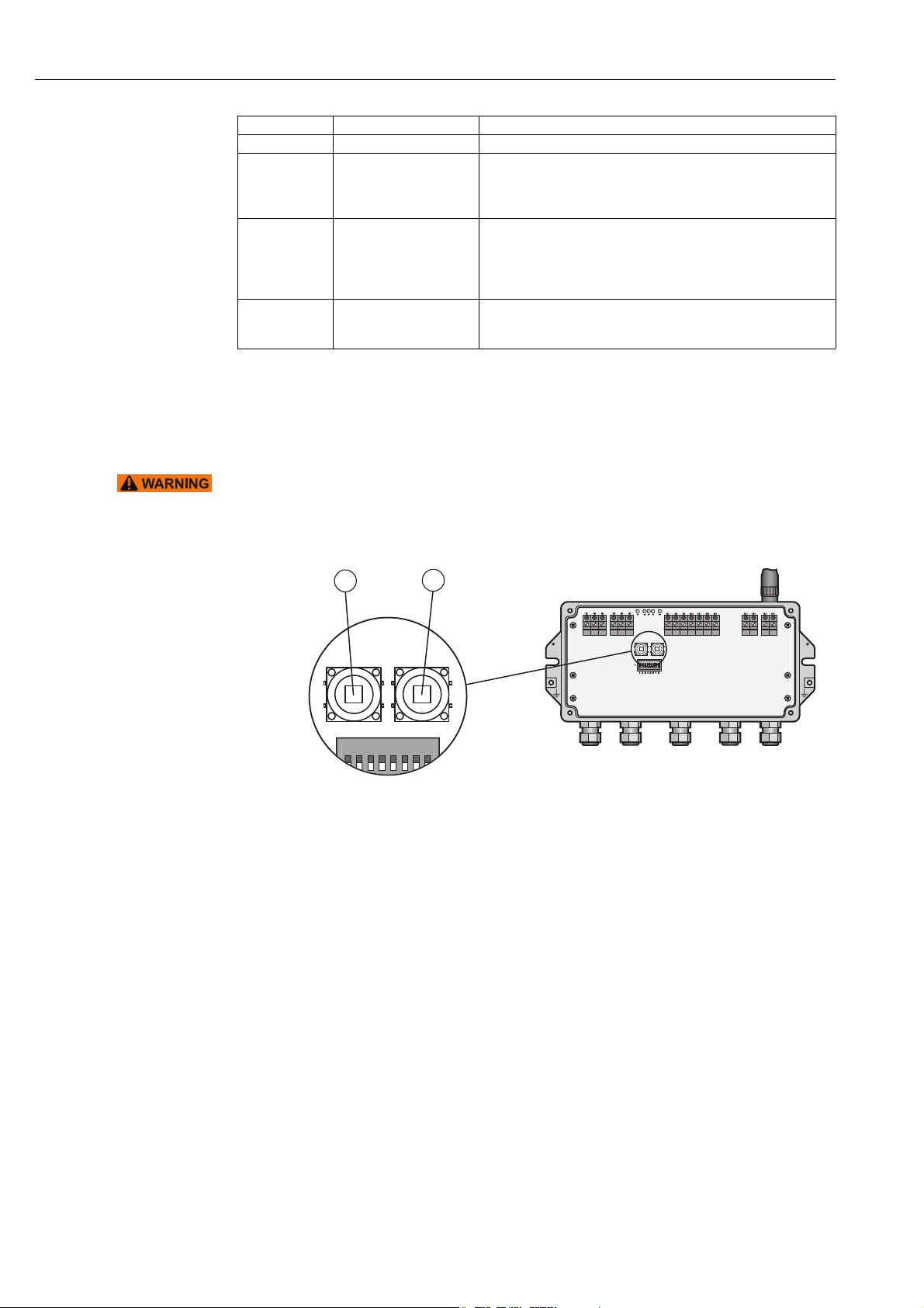
6.1.2 Buttons
Fieldgate has two pushbuttons.
WARNING!
• When Fieldgate SWG70 is installed in Ex-Zone 2 and the power is switched on, the
operation of the pushbuttons is permitted only in the absence of any potentially explosive
atmosphere.
Fig. 6-3: Pushbuttons
1Button P1 2Button P2
28 Endress+Hauser
Page 29
WirelessHART Fieldgate SWG70 Operation
+24V +24V
0V 0V
LINE1 LINE2
A
B
SHD
RS485
T1
T2
RX–
RX+
TX–
TX+
ON
OFF
SHD
A
B
SHD
RS485
ETHERNET
1
2
3
4
ON
OFF
1 234 5678
The function of the buttons is as follows:
Buttons
Buttons Function Procedure
Button P1 Configuration reset Press the button for more than 3 seconds.
– All Fieldgate SWG70 configuration parameters are reset to
factory settings with exception of the parameters set by button
P2 and button P1 + P2.
– After approx. 3 seconds, all LEDs light up to confirm the reset.
Button P2 Communication reset Press the button for more than 3 seconds.
– All Fieldgate SWG70 configuration parameters related to the
wired communication channels are reset to factory settings.
– After approx. 3 seconds, all LEDs light up to confirm the reset.
Button P1 + P2
DIP switch 8 OFF
Password reset Press buttons P1 and P2 simultaneously for more than 3 seconds.
– All Fieldgate SWG70 passwords are reset to the factory settings.
– Passwords are used for access to the Command Line Interface
and the Web Server (HTTPS).
– For Web Server User name: admin; Password: admin
– After approx. 3 seconds, all LEDs light up to confirm the reset.
Button P1 + P2
DIP switch 8 ON
Network manager reset Press buttons P1 and P2 simultaneously for more than 3 seconds.
– The Fieldgate SWG70 join key, network ID, radio power and
access mode are reset to factory settings.
– After approx. 3 seconds, all LEDs light up to confirm the reset.
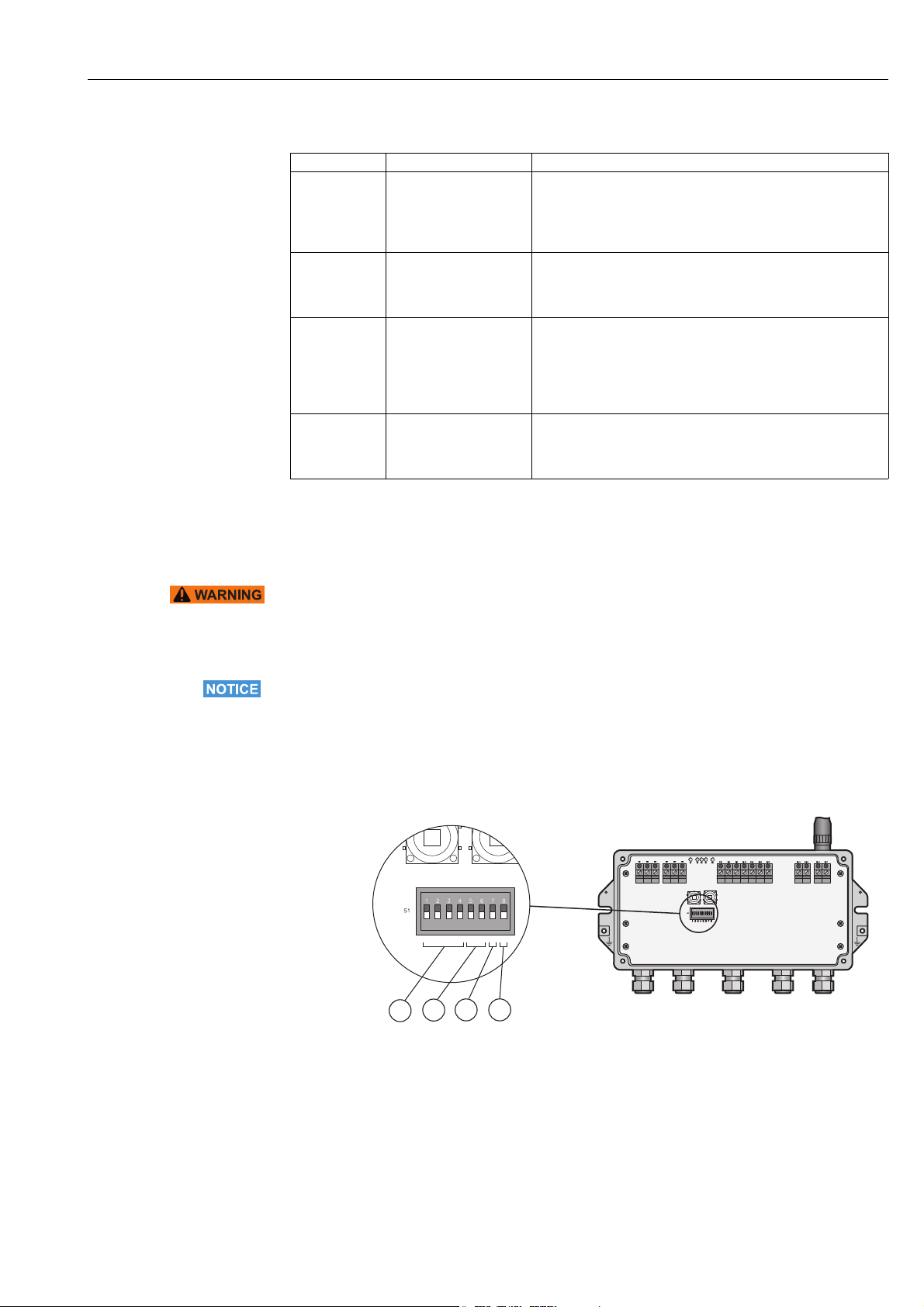
6.1.3 DIP switches
WARNING!
• When Fieldgate SWG70 is installed in Ex-Zone 2 and connected to the power supply, the
operation of DIP switches is permitted only in the absence of any potentially explosive
atmosphere.
NOTICE!
• The same functions can be initiated from the Fieldgate SWG70 Web interface and DTM.
See Chapter 8.3 "Interfaces (wired communication)" on page 48.
Fieldgate SWG70 has one 8-gang DIP switch. Fieldgate SWG70 is delivered with all DIP
switches set to ON and with all DIP switch functions set by software controls.
Fig. 6-4: DIP switches
1 DIP switches 1 to 4: HART device address
2 DIP switches 5 and 6:
Baud rate of RS-485 interface
3 DIP switch 7: RS-485 terminating resistor
4 DIP switch 8: Security mode
Endress+Hauser 29
Page 30

Operation WirelessHART Fieldgate SWG70
DIP switch positions
Switch Function 1234Value1234Value
1 – 4 HART device address
5 and 6 Baud rate of RS-485
interface
7 RS-485 termination • OFF = disconnected • ON = connected
8 Download
Join Key/Network ID
1) You can set up HART device addresses from 0 to 63 by software.
1)
OFF OFF OFF OFF 0 OFF OFF OFF ON 8
ON OFF OFF OFF 1 ON OFF OFF ON 9
OFF ON OFF OFF 2 OFF ON OFF ON 10
ON ON OFF OFF 3 ON ON OFF ON 11
OFF OFF ON OFF 4 OFF OFF ON ON 12
ON OFF ON OFF 5 ON OFF ON ON 13
OFF ON ON OFF 6 OFF ON ON ON 14
ON ON ON OFF 7 ON ON ON ON 15
56Value 56Value
OFF OFF 9600 bit/s OFF ON 38400 bit/s
ON OFF 19200 bit/s ON ON 57600 bit/s
• OFF = disabled • ON = enabled
Security mode When DIP switch 8 is OFF, it is not possible to download the Network ID and the Join Key to
the Fieldgate. See Chapter 8.3.2 "Serial (RS-485)" on page 49. Fieldgate SWG70 is delivered
with the download enabled by default, i.e. DIP switch 8 is ON.
30 Endress+Hauser
Page 31

WirelessHART Fieldgate SWG70 Commissioning
7 Commissioning
NOTICE!
• We recommend that you first set up the Fieldgate SWG70, the WirelessHART Adapters
and the HART devices on a test bench and test the network.
The Fieldgate SWG70 can be set up in the following ways:
• Via the Ethernet connection using the Web server
• Via the Ethernet connection using FieldCare and Fieldgate-DTM
• Via the RS-485 connection using FieldCare and Fieldgate-DTM
The structure of the parameter blocks and the parameters in the Fieldgate DTM and the Web
server in the Fieldgate are identical.
Web server The Fieldgate SWG70 has an integrated Web server.
You can set up the Fieldgate and the associated WirelessHART network via the Web server.
See Chapter 7.1 for details on setting up the Fieldgate SWG70 via the Web server.
FieldCare You can set up the Fieldgate and the associated WirelessHART network via FieldCare. In
addition, you can also configure the WirelessHART Adapters SWA70 and the connected
devices via FieldCare.
A prerequisite is that the WirelessHART Adapters and devices already use the same join key
and network identifier as Fieldgate SWG70 and have joined the network. Configure
connected WirelessHART Adapters and field devices via the relevant DTMs.
NOTICE!
• It is advisable to configure the adapters and connected HART devices via a direct
connection. See Operating Instructions BA00061S/04/en. If FieldCare accesses the
devices via the Fieldgate SWG70 DTM, the response times may be considerably longer
than for a direct connection.
See Chapter 7.1 and Chapter 7.3. for details on setting up the Fieldgate SWG70 via
FieldCare.
7.1 Ethernet connection
The Ethernet connection of Fieldgate SWG70 allows communication with a computer via the
integral Web Server or via FieldCare.
The following requirements must be met:
• Internet Protocol TCP/IP is installed on your computer and is active.
• You have administration rights for your computer and network.
• You have an set of IP addresses that have been authorized by your IT department.
• Any proxy server for your Internet Browser is disabled.
• Firewalls allow communication on port 80, 433, 502, 3333 and 5094.
Fieldgate SWG70 is delivered with the default IP address:
• 192.168.1.1
Endress+Hauser 31
Page 32

Commissioning WirelessHART Fieldgate SWG70
NOTICE!
• By default, the IP address of the WirelessHART Fieldgate EtherNet/IP version is
automatically assigned via DHCP. Please contact your network administrator to identify
the automatic set IP address, if necessary.
rd
•Alternative 3
party IP scanner software i.e. "BOOTP Utility Software" from Rockwell
Automation enables you to scan the Ethernet network and being able to assign a dedicated
IP address i.e. 192.168.1.1 to the WirelessHART Fieldgate. Please consider WirelessHART
Fieldgate MAC address is required to be able to set a dedicated IP address with "BOOTP
Utility Software" from Rockwell Automation.
• Please find below path to Rockwell Automation "BOOTP Utility Software" download and
instruction page:
1. Go to http://www.rockwellautomation.com
2. Click "Products"
3. Click "Reliance Electric Drives"
4. Click "Software”"
32 Endress+Hauser
Page 33

WirelessHART Fieldgate SWG70 Commissioning
7.1.1 Establishing the connection between the host computer and the Fieldgate SWG70 Web server
Prerequisite
The Fieldgate SWG70 is connected to the Ethernet network. See Chapter 5.3 "Connecting
to Ethernet" on page 22.
Procedure 1. Check that the computer can reach the Fieldgate via ports 80, 443, 502, 3333 and
5094. Please contact your network administrator if necessary.
2. Note the current settings for the IP address and network/subnet mask of the computer
to restore them if necessary.
3. Change the IP address and the network/subnet mask of your computer:
– IP address 192.168.1.200
– Network/subnet mask 255.255.255.0.
4. The simplest way to check the connection is to call up the Fieldgate SWG70 Web
server. For this, enter the default IP address of the Fieldgate SWG70 in your Internet
browser: 192.168.1
5. Accept the site certificate in the dialog which now appears.
6. The Login of the Web page appears.
– To open the Fieldgate SWG70 Web page, enter the User name
(default: admin) and the Password (default: admin) and click OK.
– You must change the password after logging in for the first time.
7. If the connection to the Fieldgate Web server fails, check the following points:
– Are all the proxy servers in the browser switched off or not used for this address
range?
– Are ports 80, 443, 502, 3333 and 5094 open in all the firewalls?
– Are you using the correct Ethernet cable? See Chapter 5.3 "Connecting to Ethernet" on
page 22.
– Is the Ethernet cable correctly connected? See Chapter 5.3 "Connecting to Ethernet" on
page 22.
Endress+Hauser 33
Page 34

Commissioning WirelessHART Fieldgate SWG70
7.2 RS-485 connection
Prerequisite
The Fieldgate SWG70 is connected to the RS-485 bus. See Chapter 5.4 "Connecting to
RS-485" on page 24.
Procedure 1. Connect the RS-485 bus to your computer via an RS-485/RS-232 signal converter or
an RS-485/USB signal converter.
2. If you are using an RS-485/USB signal converter, install the correct driver.
3. Open the Windows device manager to find out which COM port the converter is
connected to. For this purpose, enter "Device manager" in the search window in the
Windows Start menu.
4. The signal converter and the assigned COM port are displayed under "Ports (COM &
LPT)".
5. Note the COM port (in this case USB Serial Port (COM5)) and the baudrate etc. as you
will need them to set up communication.
7.3 Creating a FieldCare project
Creating a FieldCare project will allow you to configure Fieldgate SWG70 and any HART
device (field device or adapter) in the wireless network via its DTM. The configuration of a
field device can be taken from the manufacturer’s operating manual, the configuration of
the adapter is described in Operating Instructions BA00061S/04/en, SWA70 Wireless
Adapter.
7.3.1 Adding the HART IP CommDTM
The HART IP CommDTM is required for communication via Ethernet with FieldCare.
NOTICE!
• If you wish to connect to FieldCare via the RS-485 interface, the HART Communication
CommDTM must be added and configured instead of the HART IP CommDTM.
• The procedure is similar to that described here, whereby the configuration involves other
parameters such as selection of multiplexer option, COM port and baudrate.
34 Endress+Hauser
Page 35

WirelessHART Fieldgate SWG70 Commissioning
1. In the FieldCare project workspace, right-click on the Host Computer node and select
Add Device:
2. The Add New Device dialog opens:
– Select HART IP Communication and press OK.
– The dialog closes and the HART IP Communication DTM is added below the Host
node.
3. If desired, the HART IP Communication DTM can be now configured offline.
– Right-click on the node and select Configuration.
– The node name and timeout (default 10000 ms) can be changed.
– The changes are accepted when the Apply button is pressed.
Endress+Hauser 35
Page 36

Commissioning WirelessHART Fieldgate SWG70
7.3.2 Adding the Fieldgate SWG70
1. Right-click HART IP Communication and select Add Device:
2. The Add New Device dialog opens:
– Select WirelessHART Fieldgate SWG70 and press OK.
3. The dialog closes and the Fieldgate SWG70 DTM is added below the HART IP node.
4. If the factory IP address (192.168.1.1) or the Ethernet Port (5094) of the Fieldgate
SWG70 has been changed, right-click on the HART IP Communication node and select
Additional Functions => Set DTM Addresses...
– The Set DTM Addresses Dialog opens:
5. Enter the new IP address and/or Ethernet UDP Port number and press Update Changed
Data.
6. Close the dialog – the Fieldgate SWG70 can now be put online.
36 Endress+Hauser
Page 37

WirelessHART Fieldgate SWG70 Commissioning
7.3.3 Parameterizing Fieldgate SWG70
1. Right-click HART IP Communication and select Connect:
– The HART IP CommDTM is put on-line and the two arrows turn green.
2. Right-click on the Fieldgate SWG70 node and select Connect.
– The Fieldgate SWG70 DTM is put on-line and the two arrows turn green.
3. Right-click on the Fieldgate SWG70 node and select Online Parameterize:
– The DTM of Fieldgate SWG70 opens.
4. Expand all the submenus of the directory tree to reveal the parameter blocks. (The
"Identification" page is open in the graphic below):
– You are now ready to configure the device. See Chapter 8 "Fieldgate configuration" on
page 42.
Endress+Hauser 37
Page 38

Commissioning WirelessHART Fieldgate SWG70
7.3.4 Scanning for wireless devices in the network
After Fieldgate SWG70 has been configured, see Chapter 8.2 onwards, you may want to
scan for other devices in the network.
1. Right-click on the Fieldgate SWG70 node and select Create Network..:
– You can also click on the Create Network icon to do this.
– The Fieldgate SWG70 is put on-line and the two arrows turn green.
2. The Fieldgate CommDTM now scans the wireless network and automatically adds all
WirelessHART devices found to the network (in our case the SWA70 adapters):
NOTICE!
• If no device is found although communication has been established, check that the
adapters have been configured with the correct network identification and join key.
• It may take up to ten minutes for a wireless device to join the network after download of
the Network ID and Join Key.
• To increase the performance of a connection to an adapter it is possible to open a fast pipe.
See Chapter 8.2.3 "Operating Modes" on page 47.
38 Endress+Hauser
Page 39

WirelessHART Fieldgate SWG70 Commissioning
7.3.5 Scanning for devices connected to adapters
It is also possible to scan for the devices connected to the adapters. Depending on the size of
the network and the connected field devices, however, it is possible that time out problems
occur. In this case, FieldCare issues a warning and the user can choose to cut the connection,
wait for connection or retry the connection.
1. Open a fast pipe to the corresponding adapter. See Chapter 8.2.3 "Operating Modes" on
page 47.
2. Right-click on the Adapter node and select Create Network...:
– You can also click on the Create Network icon to do this.
3. The adapter DTM now scans the wired interface and automatically adds all the HART
devices found to the network (in this case, the temperature transmitter TMT162):
– Depending upon FieldCare configuration and number of devices, this may occur
automatically or after confirmation with OK in the Scanning Result dialog.
– Depending upon FieldCare configuration, if only one device is found, the
corresponding Device DTM will open, see below.
4. Repeat the process for all adapters in the network.
5. To open the Device DTM of an unconnected transmitter right-click on the Transmitter
node and select Connect, then right-click again and select Online Parameterization.
Endress+Hauser 39
Page 40

Commissioning WirelessHART Fieldgate SWG70
7.4 User interface
The Web Server and DTM of the Fieldgate SWG70 are structured in the same manner, so
that the configuration is identical. Before starting, the Web Server must be open, (see
Chapter 7.1.1) or the Online parameterization dialog of the DTM must be open, see
(Chapter 7.3.3). The user interface is structured as follows:
Structure Chapter Modbus OPC EtherNet/IP
Fieldgate configuration Chapter 8
Identification Chapter 8.1 X X X
Wireless Communication Chapter 8.2 X X X
Basic Setup and
Advanced Setup
Operating Modes Chapter 8.2.3 X X X
Interfaces (wired communication) Chapter 8.3 X X X
Ethernet Chapter 8.3.1 X X X
Serial (RS-485) Chapter 8.3.2 X X X
Protocols (wired communication) Chapter 8.4
Modbus via Ethernet or RS-485 Chapter 8.4.1 X
EtherNet/IP via Ethernet Chapter 8.4.2 X
HART via Ethernet or RS-485 Chapter 8.4.3 X X X
AMS via Ethernet Chapter 8.4.4 X X X
Diagnostics Chapter9XXX
Identification Chapter 9.1 X X X
Wireless Communication Chapter 9.2 X X X
Overview Chapter 9.2.1 X X X
Details Chapter 9.2.2 X X X
Burst Lists Chapter 9.2.3 X X X
Topology View (Diagnostics) Chapter 9.2.4 X X X
Wired Communication Chapter9.3XXX
Overview Chapter 9.3.1 X X X
HART Chapter 9.3.2 X X X
Engineering Chapter 10 X X X
Instrument List Chapter 10.1 X X X
General Chapter 10.1.1 X X X
Creating and editing an Instrument List Chapter 10.1.2 X X X
Topology View (Engineering) Chapter 10.2 X X X
Configuring Modbus Chapter 10.3 X X
Modbus Settings Chapter 10.3.1 X
Input Status Chapter 10.3.2 X
Input Register Chapter 10.3.3 X
Configuring a WirelessHART OPC server Chapter 10.4 X
System architecture of an OPC WirelessHART network Chapter 10.4.1 X
Configuring the WirelessHART OPC server with "WirelessHART
Fieldgate OPC Configurator"
Description of the WirelessHART Fieldgate OPC Configurator Chapter 10.4.3 X
Configuring bursts using the WirelessHART OPC server Chapter 10.4.4 X
EtherNet/IP configuration Chapter 10.5 X
Setting up an EtherNet/IP connection Chapter 10.5.1 X
Assigning data exchange connections via HART descriptors Chapter 10.5.2 X
Burst commands for cyclic data exchange Chapter 10.5.3 X
Integrating SWG70 into a PLC via EtherNet/IP Chapter 10.5.4 X
Cyclic data exchange via the ControlLogix® controller system Chapter 10.5.5 X
Connection parameters for cyclic data exchange Chapter 10.5.6 X
Diagnostic bits in cyclic data exchange Chapter 10.5.7 X
Chapter 8.2.1
and
Chapter 8.2.2
Chapter 10.4.2 X
XXX
40 Endress+Hauser
Page 41

WirelessHART Fieldgate SWG70 Commissioning
Structure Chapter Modbus OPC EtherNet/IP
Downstream Communication (for discreet field devices) Chapter 10.6 X X
Substitution value (substitution value to DCS) Chapter 10.7 X X
Burst message monitoring Chapter 10.7.1 X X
Factory Acceptance Test (FAT) Chapter 10.7.2 X X
Security – Whitelist, Temporary Join Key Chapter 10.8 X X
Additional Functions Chapter 11 X X X
Reset Chapter 11.1 X X X
Self Test Chapter 11.2 X X X
Firmware Upgrade (Web Server) Chapter 11.3 X X X
Change Password (Web Server) Chapter 11.4 X X X
Set DTM Addresses (DTM) Chapter 11.5 X X X
Set Device Addresses (DTM) Chapter 11.6 X X X
Upload Certificate (Web server) Chapter 11.7 X X X
Auto Refresh Chapter 11.7 X X
Measurement Chapter 12 X X X
The Web interface differs from the DTM only in the presentation of the parameters. In the
case of the Web interface, the parameters are presented in a single tree. In the case of the
DTM, configuration, diagnostics and other functions are presented in separate DTM dialog
boxes. To open the dialog boxes, you must right-click the Fieldgate SWG70 and select the
desired option from the context menu. The DTM offers addition functions which are FDTframe specific, e.g. Set Device Addresses. In both cases parameters are registered by pressing
Enter. In some cases, in which more than one parameter is registered, an additional button
must be pressed for the changes to take effect.
Endress+Hauser 41
Page 42

Fieldgate configuration WirelessHART Fieldgate SWG70
8 Fieldgate configuration
Parameter contains all parameters related to the set-up of Fieldgate SWG70. In the case of
FieldCare, right-click Fieldgate SWG70 and select Online Parameterize.
8.1 Identification
Th e pa rame ter s to be f oun d in thi s le af p erta in to the identification of Fieldgate SWG70. The
default parameters of Fieldgate SWG70 will appear in the appropriate input fields.
1. Click Parameters => Identification to display the associated parameters:
Identification parameters
2. Enter at least a Device Long Tag and a Device Tag, pressing Enter to register the
change.
Parameter Meaning Default
Device Long Tag Identifies Fieldgate within the plant network
– Max. 32 character ASCII "Latin 1" string
Device Tag Identifies Fieldgate within the plant network
– Max. 8 character HART Packed ASCII string*
Descriptor User text describing, e.g. function or location of Fieldgate SWG70
– Max. 16 character HART Packed ASCII string*
Date Date in dd.mm.yyyy format; you can enter any date here, e.g. the date of
the last configuration
Message User message, to be transmitted with information from the adapter
– Max. 32 character HART Packed ASCII string*
Serial number Indicates serial number of connected Fieldgate SWG70 –
Ext. Order Code Indicates order code of connected Fieldgate SWG70 –
Order Code Indicate order identification of the connected Fieldgate SWG70 –
Country Code Country in which the Fieldgate is to be used - select from list
– Governs the signal strength that can be set for the device
* Valid character set: @ A B C D E F G H I J K L M N O P Q R S T U V W X Y Z
[ \ ] ^ _ blank ! " # $ % & ' ( ) * + , - . / 0 1 2 3 4 5 6 7 8 9 : ; < = > ?
–
–
–
01.04.2009
–
Germany
42 Endress+Hauser
Page 43

WirelessHART Fieldgate SWG70 Fieldgate configuration
8.2 Wireless Communication
8.2.1 Basic Setup
This leaf contains the parameters required to set up the WirelessHART communication
offered by the Fieldgate SWG70.
1. Click Parameter > Wireless Communication > Setup, to display the associated
parameters.
Basic Setup parameters
Parameter Meaning Default
Network Tag 32-character network identification tag of Fieldgate SWG70 –
Network ID Unique identification number of the network: Valid range 0-65535 1447
Join Key Part 1 of 4 User network password, 8 hexadecimal characters, Part 1 of 4 456E6472
Join Key Part 2 of 4 User network password, 8 hexadecimal characters, Part 2 of 4 65737320
Join Key Part 3 of 4 User network password, 8 hexadecimal characters, Part 3 of 4 2B204861
Join Key Part 4 of 4 User network password, 8 hexadecimal characters, Part 4 of 4 75736572
Execute Join Click the button to download your changes and restart the network. The
"Join Key" is sent to all network subscribers and changed.
RTC Date Real time clock (RTC) – date, date setting for the network
RTC Time Real time clock (RTC) – time, time setting for the network
Network start date Indicates the date on which the network was created
Network start time Indicates the time at which the network was created
Allow New Devices Determines whether new devices are allowed to join the network
Radio Power Determines power of the radio signal emitted by the device
Bandwidth Profile Determines Fieldgate’s bandwidth profile Normal
Global Advertising
Timeout
Activate Global
Advertising
Enter the date in the following format: DD/MM/YYYY. The parameter is
only available in the online mode.
Enter the time in 24-hour format: hh:mm:ss. The parameter is only
available in the online mode.
• All: any device can join the network
• None: no device can join the network
– Selection and default value depend on the Country Code
– Observe local restrictions for 2.4 GHz equipment
Determines the period for global advertising on network start-up –
Click this button to activate global advertising –
–
–
–
All
–
Endress+Hauser 43
Page 44

Fieldgate configuration WirelessHART Fieldgate SWG70
NOTICE!
•The Join Key parameters can only be entered when DIP switch 8 (inside the Fieldgate
housing) is set to ON (factory default). See Chapter 6.1.3 "DIP switches" on page 29.
Basic Setup Procedure 1. Click on Parameter => Wireless Communication => Setup
2. Enter the following parameters, pressing Enter after each change:
–Network Tag
–Network ID
– Join Key Part 1 to Part 4.
3. If your national regulations require it, set the radio power to 0dBm (most allow
10 dBm).
4. Leave all other parameters at their default values, unless you want to activate global
advertising and/or change the bandwidth profile.
5. Click the Execute Join button to download the join key.
– The following message appears:
6. Click Yes to confirm.
– The following message appears:
7. Click OK to acknowledge the message.
8. To start the network, select Reform Network in Additional Functions > Reset. See
Chapter 11.1 "Reset" on page 106.
9. The wireless network is now up and running.
44 Endress+Hauser
Page 45

WirelessHART Fieldgate SWG70 Fieldgate configuration
Bandwidth Profile This option allows you to increase network performance by reducing network latency. If bat-
tery power is being used, this option increases energy consumption and reduces battery life.
If a faster response time is more important than battery life, set the profile to medium or
high.
To activate the profile, choose Reform Network in Additional Functions => Reset. See
Chapter 11.1 "Reset" on page 106.
Global Advertising If Global Advertising is activated, the Fieldgate and the network devices issue a series of
identification messages at a rate higher than normal to identify new wireless devices and to
reduce the network join time. The messages are sent until the Global Advertising Timeout
is reached.
As Global Advertising increases energy consumption of the network devices it is recommended that it is activated only when needed, e.g. during the set up of the network.
1. Enter a Global Advertising Timeout (1 ... 255 minutes)
2. Click the Activate Global Advertising button; advertising starts immediately.
8.2.2 Advanced Setup
Channel Blacklist With WirelessHART technology, Fieldgate SWG70 offers users a self-managed and self-
healing wireless network. If several wireless networks are being operated at one location,
the Fieldgate automatically selects the optimum channel assignment. If new networks are
added, the channel assignment is adapted automatically.
Alternatively, you can also configure the channel assignment manually. Note that a WLAN/
Wi-Fi channel based on the IEEE 802.11 standard is wider than a WirelessHART channel
based on the IEEE 802.15.4 standard. The numbering of the channels is different for
WLAN/Wi-Fi and WirelessHART.
Channel numbering
WLAN/WiFi
1 1 to 4 8 8 to 11
2 2 to 5 9 9 to 12
3 3 to 6 10 10 to 13
4 4 to 7 11 11 to 14
5 5 to 8 12 12 to 15
6 6 to 9 13 13 to 15
77 to 10
Channel numbering
WirelessHART
Channel numbering
WLAN/WiFi
Channel numbering
WirelessHART
Example: If the WLAN uses channel 5, channels 5 to 8 in the WirelessHART network must
be disabled.
Endress+Hauser 45
Page 46

Fieldgate configuration WirelessHART Fieldgate SWG70
Disabling channels 1. Disable a channel by deactivating its check box in the Channel Blacklist.
– The number of remaining active channels must be odd.
– At least 5 channels must remain active.
2. Click Send to Device to transfer the updated blacklist settings to the Fieldgate.
– Fieldgate stores the updated blacklist: the updated settings do not apply until the
network is reformed.
3. Go to Additional Functions > Reset, and click Reform Network to apply the updated
channel blacklist. See Chapter 11.1 "Reset" on page 106.
46 Endress+Hauser
Page 47

WirelessHART Fieldgate SWG70 Fieldgate configuration
8.2.3 Operating Modes
Operating Modes contains a table listing all devices in the WirelessHART network together
with their operation modes.
Whenever a wireless device joins the network, it is automatically inserted into the list, provided it is not already listed. Wired HART devices connected to a WirelessHART Adapter
(SWA70) are also listed. The list retains all the devices Fieldgate has detected over the lifetime of the network, i.e. if a device is completely removed from the network, it will still be
seen in the list. Such devices can be removed from the Operating Modes list by clicking on
the button
– Click on Parameter > Wireless Communication > Operating Modes to display the
which appears next to them.
table.
Parameter Meaning
Long Tag Identifies Fieldgate within the plant network
IO card Indicates the virtual I/O card number to which the device is mapped
Channel Indicates the channel of the virtual I/O card to which the device is mapped
Device Type Displays the device type as registered at the HART Communication Foundation
Status Displays the communication status
Dev. Status Displays the device status
Routing Device Indicates whether the device is allowed to act a routing device.
Fast Pipe Establishes a direct connection to a selected device. The fast pipe connection is
Enforce Identification Forces a device to resend its identification, for example if a communication failure
Flush Cache Deletes the transmitted values.
Refresh Click this button to reload the operational mode parameters of all network devices
Delete button Devices with no connection can be deleted by pressing the "Delete" button .
– For HART 5.0 or less, this is the text in the Message parameter
– Connected
– Flashing: Device connected, being identified
– Continuous: Device connected but not identified
– Communication failure
– Good
– Out of specification
– Failure
Note that the device status that is displayed in the list may differ from the actual
device status because the HART status bits may be interpreted differently.
• To deactivate the routing functionality, deactivate the corresponding check box
in the Routing Device column.
• This option enables you to set up a star network
about 4 times faster than a regular connection, which enables you to perform fast
updates.
• Click on the check box to activate the Fast Pipe.
– Note that you can activate the Fast Pipe option for only one device at a time.
occurred.
Endress+Hauser 47
Page 48

Fieldgate configuration WirelessHART Fieldgate SWG70
8.3 Interfaces (wired communication)
All Fieldgate SWG70 versions feature an Ethernet interface and a serial interface.
Depending on the device version, this interface can support different protocols.
Fieldgate
SWG70 version
SWG70-xx-1
Modbus
SWG70-xx-2
Modbus + OPC
SWG70-xx-3
EtherNet/IP
Interface Protocol
Modbus EtherNet/IP HART AMS
Ethernet X – X X
Serial (RS-485) X – X –
Ethernet X – X X
Serial (RS-485) X – X –
Ethernet – X X X
Serial (RS-485) – – X –
See this section for information about the interfaces. For information about the protocols,
see Chapter 8.4 "Protocols (wired communication)" on page 50.
8.3.1 Ethernet
The parameters contained in this leaf pertain to the set up of the communication to the host
via Ethernet interface offered by Fieldgate SWG70.
1. Click Wired Communication > Interfaces > Ethernet to display the associated
parameters:
2. Enter the parameters, pressing Enter after each change.
– Note: Automatic IP address assignment requires that there is a DHCP server in the
Ethernet network.
3. Click the Write Ethernet Information button when all parameters have been changed.
– The Fieldgate will restart with the new parameters.
– If the IP address was changed, communication will be lost.
– Change your computer's address if necessary and re-establish communication with
the new IP address.
– If you are using the HART IP CommDTM, reconfigure the communication parameters,
before making connection again. See Chapter 7.3.2 "Adding the Fieldgate SWG70" on
page 36, Step 4.
48 Endress+Hauser
Page 49

WirelessHART Fieldgate SWG70 Fieldgate configuration
Ethernet parameters
Parameter Meaning Default
IP Address
Assignment
(DHCP, DNS)
IP Address Sets fixed fieldgate IP network address for manual assignment mode 192.168.1.1
Netmask Sets subnet mask IP network address for manual assignment mode 255.255.
Gateway Address Sets default gateway TCP/IP network address
DNS 1 Sets preferred DNS server IP address for manual assignment mode
DNS 2 Sets alternative DNS server IP address for manual assignment mode
MAC Address Displays the MAC address of the WirelessHART gateway.
Write Ethernet
Information
Specifies whether Fieldgate SWG70 IP network and DNS address is to be
assigned manually or automatically.
• Manually: The settings in the dialog are used
• Automatically: The IP address of the DNS is assigned by a DHCP server
– This setting is currently not actively used by Fieldgate
– This setting is currently not actively used by Fieldgate
– This setting is currently not actively used by Fieldgate
– Note that the MAC address is a characteristic of the device itself and
cannot be changed. Each device has its own MAC address.
Downloads the changed parameters to the Fieldgate
– If the IP address was changed, communication will be lost
– If the other addresses were changed, communication will be interrupted
for a short period
Manually
255.0
0.0.0.0
0.0.0.0
0.0.0.0
–
–
8.3.2 Serial (RS-485)
The parameters contained in this leaf pertain to the set up of the serial interface offered by
Fieldgate SWG70.
Serial parameters
1. Click Wired Communication > Interfaces > Serial to display the associated
parameters:
2. Configure the serial interface for HART or Modbus RTU as required.
3. After configuration, set up the interface protocol parameters in the appropriate
"Protocol" leaf.
– Modbus serial allows access for one master. See Chapter 8.4.4 "AMS via Ethernet" on
page 52.
– HART serial allows access for one primary master and one secondary master. See
Chapter 8.4.3 "HART via Ethernet or RS-485" on page 51.
Parameter Meaning Default
Terminal Resistor
Selection
Terminal Resistor Sets the termination of the wireless fieldgate when Terminal Resistor
Protocol Selection Sets the protocol to be used over the serial port Modbus RTU
Specifies whether hardware (DIP switch 6) or software termination
settings are to be used
Selection is set to Software
– If "DIP-Switch" has been is selected, this parameter displays this setting.
Software
Disconnected
Endress+Hauser 49
Page 50

Fieldgate configuration WirelessHART Fieldgate SWG70
8.4 Protocols (wired communication)
Equipped with interface. Depending on the Fieldgate SWG70 version, different protocols can
be supported. For an overview see Chapter 8.3 "Interfaces (wired communication)" on
page 48.
8.4.1 Modbus via Ethernet or RS-485
NOTICE!
• Section 10.2 is only relevant for Fieldgate versions with Modbus,
order code: SWG70-xx-1 and SWG70-xx-2.
The parameters contained in this leaf pertain to the set up of the Modbus communication to
the host on the interfaces offered by Fieldgate SWG70.
1. Click Wired Communication > Protocols > Modbus to display the associated
parameters:
Modbus parameters
Parameter Meaning Default
Bus Address Selection Specifies whether hardware (DIP switch 0-3) or software polling address
settings are to be used
Bus Address Sets the HART address of the wireless fieldgate when Bus Address
Selection is set to Software
– When DIP-Switch is selected, displays the setting
Baud Rate Selection Specifies whether hardware (DIP switch 4–5) or software baudrate
settings are to be used
• DIP Switch Setting: 9600 Bit/s - 57600 Bit/s
• Software Setting: 1200 Bit/s - 115200 Bit/s
Baud Rate Sets the baudrate of the wireless fieldgate when Baud Rate Selection is set
to Software
– When DIP-Switch is selected, displays the setting
Parity Bit Sets the number of parity bits in the Modbus RTU telegram
Stop Bit Sets the number of stop bits in the Modbus RTU telegram
Port Number
(Ethernet)
•Odd, Even or None
• 1, 1.5 or 2
Sets Fieldgate port number for Modbus TCP transmission
– If the port number is changed, the default port remains open
– Modbus TCP allows access for up to five masters
Software
1
Software
38400
Odd
1
502
50 Endress+Hauser
Page 51

WirelessHART Fieldgate SWG70 Fieldgate configuration
8.4.2 EtherNet/IP via Ethernet
You do not need to make any settings for the EtherNet/IP protocol.
8.4.3 HART via Ethernet or RS-485
The parameters contained in this leaf pertain to the set up of the HART communication to
the host on the interfaces offered by Fieldgate SWG70.
1. Click Wired Communication => Protocols => HART to display the associated
parameters:
HART parameters
2. If the default port number is changed, and FieldCare is in use, communication will be
lost.
3. Reconfigure the HART IP CommDTM communication parameters, before making
connection again. See Chapter 7.3.2 "Adding the Fieldgate SWG70" on page 36, Step 4.
Parameter Meaning Default
Bus Address Selection Specifies whether hardware (DIP switch 0–3) or software bus address
settings are to be used
• DIP switch: 0 –15
•Software: 0 –63
Bus Address Sets the HART address of the wireless fieldgate when Bus Address
Selection is set to Software
– When DIP-Switch is selected, displays the setting
Baud Rate Selection Specifies whether hardware (DIP switch 4–5) or software baudrate
settings are to be used
• DIP switch: 9600 Bit/s –57600 Bit/s
• Software: 1200 Bit/s –115200 Bit/s
Baud Rate Sets the baudrate of the wireless fieldgate when Baud Rate Selection is set
to Software
– When DIP-Switch is selected, displays the setting
Port Number Sets the Fieldgate SWG70 Ethernet port number for HART via UDP/TCP
transmission
– If the port number is changed, the default port remains open
– HART UDP allows access for two primary masters and two secondary
masters
– HART TCP allows access for one primary masters and one secondary
master
Software
1
Software
19200
5094
Endress+Hauser 51
Page 52

Fieldgate configuration WirelessHART Fieldgate SWG70
8.4.4 AMS via Ethernet
If you would like to integrate Fieldgate SWG70 into Emerson’s Asset Management System
(AMS), this must be done via an Ethernet port. In rare cases you will need to change the port
number. The default port setting is "33333".
1. Click Wired Communication > Protocols > AMS.
52 Endress+Hauser
Page 53

WirelessHART Fieldgate SWG70 Diagnostics
9Diagnostics
Diagnosis contains all health and related information on Fieldgate SWG70. In FieldCare the
corresponding function is called by right-clicking on the Fieldgate SWG70 node and selecting Diagnostics.
9.1 Identification
The Identification leaf contains information on the hardware and software of Fieldgate
SWG70.
1. Click Diagnostics > Identification to display the associated parameters:
Identification parameters
Parameter Meaning
Device Long Tag Identifies Fieldgate within the plant network
Device Tag Identifies Fieldgate within the plant network
Descriptor User text describing, e.g. function or location of Fieldgate
Date Indicates a date
Message User message, transmitted with information from Fieldgate SWG70
Universal Command
Revision
Device Revision HART Revision of device specific commands supported by Fieldgate SWG70
Software Revision HART Software revision of Fieldgate SWG70
Gateway Software Versions Indicates the firmware version installed in Fieldgate SWG70
Serial number Indicates serial number of connected Fieldgate SWG70
Order Code Indicates order code of connected Fieldgate SWG70
Order Ident Indicate order identification of the connected Fieldgate SWG70
Country Code Country Code to which Fieldgate SWG70 is set
Assembly Number The assembly number of Fieldgate SWG70
Revision of the HART protocol supported by Fieldgate SWG70
Endress+Hauser 53
Page 54

Diagnostics WirelessHART Fieldgate SWG70
9.2 Wireless Communication
The Wireless Communication leaf contains information on the operation of Fieldgate
SWG70 within the wireless network.
9.2.1 Overview
Overview provides information about the I/O interfaces of the wireless network as well as
network statistics.
1. Click Diagnostics > Wireless Communication > Overview to display the associated
parameters:
"Wireless Communication
- Overview" parameters
Parameter Meaning
I/O System Capabilities
Max. Card Number Indicates the maximum number of cards in the I/O system. This corresponds to the
maximum number of wireless devices that can be connected to the gateway.
Max. Channel Number Indicates the maximum number of channels.
Max. Sub Dev. Number Indicates the maximum number of sub devices that can be connected to a specific
channel.
Number of Devices Indicates the current number of subdevices.
– Every device counts as a subdevice, no matter if it is a wireless device or a wired
device connected to a WirelessHART Adapter (SWA70).
Lifetime Network Statistics
Reliability Ratio of the number of successful packet transmissions to the sum of the successful
and permanently lost packet transmissions taken across the entire network
Stability Ratio of the number of successful packet transmissions to the sum of the successful
and unsuccessful packet transmissions taken across the entire network.
– Unsuccessful transmissions are repeated for as many time as necessary using all
communication paths available. If the repeat process is interrupted, e.g. by
removing the device from the network, then the corresponding packets are
counted as lost.
Latency Average time taken for packets generated by the wireless devices to reach the
gateway.
Lost Upstream Packages Total number of packets generated by the wireless devices that were lost when
transferred over the network.
54 Endress+Hauser
Page 55

WirelessHART Fieldgate SWG70 Diagnostics
9.2.2 Details
NOTICE!
• Diagnostic information is available only after the applicable statistics period has been
completed (15 minutes). During this time, some information is set to 0 or replaced by
wildcard characters.
Details shows all devices in the WirelessHART network together with their diagnostic
information.
Whenever a wireless device joins the network, it is automatically inserted into the list if it is
not already there. Wired HART devices connected to a WirelessHART Adapter (SWA70) are
also listed. To remove a device from the list, use the Instrument List. See Chapter 10.1
"Instrument List" on page 62.
1. Click on Diagnostics > Wireless Communication > Details:
Wireless Communication
Details parameters
Parameter Meaning
Tree-View Deselect this option to sort devices by their sub-device index value
Instrument Identification Displays information identifying the device:
• Long Tag: Long Tag of connected device
• IO card: Identifier of fieldgate card used by the device
• Channel: Identifier of card channel used by the device
• Device Type: Designation of connected device
• Status: Communication status of the associated device
– Connected
– Flashing: Device connected, being identified
– Continuous: Device connected but not identified
– Communication failure
• Dev. Status: Device status of the associated device
– Good
– Out of specification
– Failure
Note that the device status that is displayed in the list may differ from the actual
device status because the HART status bits may be interpreted differently.
Number of Joins Number of times the device has joined the network
Join Time Date of the last time the device joined the network
Reliability Percentage of the packets generated by the wireless devices that were correctly
received by the gateway.
Latency Average time taken for packets generated by the wireless devices to reach the
gateway.
+/- Show/hide the list of neighboring devices
Neighbors Neighboring WirelessHART devices in reach of the selected device
RSSI Indicates the power of the signal received from the selected device by the named
neighboring device
Stability Ratio of successful packet transmissions to the total number of packet
transmissions on all wireless paths in the network
Refresh Updates the instrument list
Export Exports the details list to an Excel file
Endress+Hauser 55
Page 56

Diagnostics WirelessHART Fieldgate SWG70
9.2.3 Burst Lists
Burst mode is a special mode of a HART slave device which allows it to periodically send the
response to a selected HART command without the being polled by the master. For a WirelessHART slave device, it is the main operating mode. and can be used, for instance, to send
the process values from an adapter or connected HART device to Fieldgate SWG70 at regular
intervals.
The burst lists, contain information on the devices operating in this mode. The measured
values sent by the devices can be viewed in the Measurement List. See Chapter 11 "Additional Functions" on page 106.
1. Click on Diagnostics > Wireless Communication > Burst Lists:
Burst List parameters
Parameter Meaning
Instrument Identification Displays information identifying the device:
• Long Tag: Long Tag of connected device
• IO card: Identifier of fieldgate card used by the device
• Channel: Identifier of card channel used by the device
• Device Type: Designation of connected device
• Status: Communication status of the associated device
– Connected
– Flashing: Devices connected, identification in progress
Continuous: Devices connected but not identified
– Communication failure
• Dev. Status: Device status of the associated device
– Good
– Out of specification
– Failure
+/- Show/hide the burst list details
Burst Command Command number of selected burst commands with explanation:
• 1: Returns the primary value and units
• 2: Returns the loop current and its associated percent of range.
• 3: Returns the loop current and up to four predefined dynamic
variables and units (PV, SV, TV, QV)
• 9: Returns the value and status of up to eight device or dynamic
variables with units
• 48:Returns the complete device status information
• 77: Embeds the commands of a connected wired device so that they can be
transmitted by wireless
Num. Packets Number of burst messages sent by the network device since the last network
restart
Refresh Updates the burst list
56 Endress+Hauser
Page 57

WirelessHART Fieldgate SWG70 Diagnostics
9.2.4 Topology View (Diagnostics)
Topology view is a graphical overview of all wireless devices within your network, including
their connection status and connection paths. It is set up in Engineering => Topology View.
See Chapter 10.2 "Topology View (Engineering)" on page 65.
1. Click on Diagnostics > Wireless Communication > Topology View to open the dialog:
– The lines between the devices represent the connection paths.
– The color and thickness indicate the connection quality respectively traffic for each
connection path.
– The significance of the colors, line thicknesses and other functions are to be found in
the table which follows.
2. In the example above:
– The most traffic flows between the Adapter WAD_301 and Fieldgate SWG70_01.
– Less traffic flows between Adapter WAD_302 and WAD_303 respectively and
Fieldgate SWG70_01 as well as between Adapter WAD_302 and WAD 303
respectively and Adapter WAD_301.
– There is no traffic between Adapter WAD_302 and Adapter WAD_303, but the path
is managed as a backup path in the event of one of the other paths failing.
– The stability of all connections is good.
3. Right-click on an adapter to display its network statistics.
Endress+Hauser 57
Page 58

Diagnostics WirelessHART Fieldgate SWG70
Topology View parameters
Parameter Meaning
Traffic
Dotted line: Path is unused at the moment
Thin line: Path used by one third of connections
Medium lines: Path used by two thirds of connections
Thick line: Path used by all connections
Connection Quality
Signal Red: Signal stability 0 - 10% of maximum possible
Red: Signal stability 10 - 20% of maximum possible
Orange: Signal stability 20 - 30% of maximum possible
Gold: Signal stability 30 - 40% of maximum possible
Yellow: Signal stability 40 - 50% of maximum possible
Lime: Signal stability 50 - 60% of maximum possible
Light Green: Signal stability 60 - 70% of maximum possible
Lawn Green: Signal stability 70 - 80% of maximum possible
Bright Green: Signal stability 80 - 90% of maximum possible
Green: Signal stability 90 - 100% of maximum possible
Operating elements
Reset Zoom Resets the zoom to show everything
Refresh Updates the information on signal quality and traffic
Zoom rider – ------------ + Increases (+) or decreases (–) the magnification of the topology view
Horizontal image origin Indicates the position of the horizontal origin of the image
Vertical image origin Indicates the position of the vertical origin of the image
Resolution Sets the resolution of the image
Paths shown Selects the paths to be shown in the topology view
– All: all paths are shown
– In use: only those paths used by the network are shown
– Selected: the paths associated with a device are shown when the cursor is moved
to the said device
– None: No paths are shown
9.3 Wired Communication
The Wired Communication leaf contains information on the communication interface used
to connect to a supervisory system. It contains two submenus: Overview and HART.
9.3.1 Overview
Overview contains the performance parameters of the wired communication interface
58 Endress+Hauser
Page 59

WirelessHART Fieldgate SWG70 Diagnostics
1. Click on Diagnostics => Wired Communication => Overview to open the dialog:
Overview parameters
Parameter Meaning
Messages received through
HOST
Messages returned to HOST Total number of messages returned to the host since the start-up or last reset of
Number of requests
forwarded to IO system
Number of responses
returned from IO system
Total number of messages received from the host since the start-up or last reset of
Fieldgate SWG70.
Fieldgate SWG70.
Total number of messages from the host forwarded to the devices in the wireless
network since the start-up or last reset of Fieldgate SWG70.
Total number of messages for the host received from the devices in the wireless
network since the start-up or last reset of Fieldgate SWG70.
Endress+Hauser 59
Page 60

Diagnostics WirelessHART Fieldgate SWG70
9.3.2 HART
The HART page shows the possible statuses that may exist for HART devices in the network.
A tick box beside each parameter indicates whether the described condition is currently
valid.
– Click on Diagnostics > Wired Communication > Overview to open the dialog:
– In the case of the Cumulative Extended Device Status, the user must turn to the
Wireless Communication Details list to get more information on the individual device
status. See Chapter 9.2.2 "Details" on page 55.
60 Endress+Hauser
Page 61

WirelessHART Fieldgate SWG70 Diagnostics
Wired Communication Details parameters
Parameter Parameter Meaning
Extended Device
Malfunction
Gateway Operation in
Progress
Extended List changes Instrument List Changed Instrument list has changed since last refresh
Cumulative Device Status Primary Variable Out of
Cumulative Extended Device
Status
Device Operation in Progress "Configuration Changed bit
Manager fault Non-recoverable hardware fault: Fieldgate manager
Non-Volatile Memory Defect Non-recoverable hardware fault: Non-volatile
memory
Volatile Memory Defect Non-recoverable hardware fault: Volatile memory
Ethernet communication
fault
Electronic defect Non-recoverable hardware fault: Other case
RS-485 communication fault Non-recoverable hardware fault: RS-485 controller
Block transfer Fieldgate transferring block
Delayed answer Fieldgate awaiting answer from device (buffer)
Self test Fieldgate is in self test mode, see Chapter 8.6.5
File update Fieldgate writing to non-volatile memory file
Start-up phase Fieldgate is starting up and building the network
Active Device List Changed Device list has changed since last refresh
Limits
Non-Primary Variable Out of
Limits
Loop Current Saturated Loop current of a device in the network above 20
Loop Current Fixed Loop current of a device in the network is fixed to 4
More Status Available Device in the network has more status available
Cold Start Device in the network has cold start flagged
Configuration Changed Configuration of a device in the network has
Extended Device
Malfunction
Maintenance required The status "Maintenance required" has been set for a
Device Variable Alert The status "Device Variable Alert" has been set for a
Critical Power Failure The status "Critical Power Failure" has been set for a
reset" procedure
"Sub-Device update"
procedure
"Device update" procedure Fieldgate is carrying out the identification of an
Non-recoverable hardware fault: Ethernet controller
PV of a device in the network is out of limits
SV, TV, QV of a device in the network is out of limits
mA
mA (multidrop mode)
flagged
changed
Device in the network has malfunctioned
device in the network
device in the network
device in the network
Fieldgate has reset the "Configuration Changes" bit
of one of the devices
Fieldgate is carrying out the identification of a
device connected to an adapter
adapter
Endress+Hauser 61
Page 62

Engineering WirelessHART Fieldgate SWG70
10 Engineering
10.1 Instrument List
10.1.1 General
This leaf contains a list of instruments in the network. It is also possible to add individual
devices that are still to be connected.
1. Click on Engineering > Instrument List to open the dialog:
Instrument List
parameters
Parameter/Field Meaning
Instrument List Displays tabular information identifying the device:
• Long Tag: Long Tag of connected device
• IO card: Identifier of fieldgate card used by the device
• Channel: Identifier of card channel used by the device
• Device ID: HART serial number that is assigned at manufacturing time and that
differs for each HART device of a given type
• Extended Device Type Code: Unique code identifying the HART product family
Delete button Deletes a device from the instrument list
– Click Apply to register the change in Fieldgate SWG70
– If the device is still communicating with the network, it will automatically
reappear in the list at the next refresh
– Caution! Deleting a device from the instrument list can change the Modbus
register address if the Modbus addresses have been automatically generated.
Export/Export CSV Exports the current instrument list as a CSV file
Import/Import CSV Imports an instrument list that has been stored as a CSV file
Import Project Tree (DTM) In Offline Parameterize dialog, imports the network view to the Instrument List
Refresh Updates the instrument list
– After switching on or resetting the device, wait at least one minute before
pressing the Reset button.
Apply Stores the current instrument list in Fieldgate SWG70
62 Endress+Hauser
Page 63

WirelessHART Fieldgate SWG70 Engineering
10.1.2 Creating and editing an Instrument List
Normally the Instrument List is only generated once the Refresh button is pressed after the
network is up and running. It is possible, however, to create a list from scratch before any
WirelessHART devices join the network. This allows the order in which the devices are displayed in the both the Instrument List and Operating Modes - and hence in the Modbus
mapping - to be predetermined. The individual entries can also be edited.
NOTICE!
• When editing the instrument list, incomplete entries are highlighted in red. These data
must be entered or corrected before the instrument list can be downloaded to Fieldgate
SWG70.
• Entries marked with yellow already exist: the copies must be removed.
Procedure for Web Server 1. Click on Engineering > Instrument List to display the instrument list.
2. To add a device, click into the last row of the instrument list and enter the Long Tag of
the device.
3. Enter the following optional additional parameters by clicking on the appropriate field:
– I/O Card to which the device should be attached.
– Channel: adapters are assigned to Channel 0, devices to Channel 1.
– Device ID: unique HART serial number assigned on manufacture of the device.
– Extended Device Type Code: unique code identifying the HART family type. press
Enter to confirm your entries.
NOTICE!
• If the values of the fields "Device ID" and "Extended Device Type Code" are unknown, "0" must
be entered.
4. When the instrument list is complete, press Apply to download it to Fieldgate SWG70.
5. When the devices join the network at a later time, they will be assigned to their allotted
positions in the Operating Modes list.
6. When all devices have joined the network, return to the Instrument List and press
Refresh to import the latest list.
7. Click Export to store a copy of the list on your computer as a CSV file.
– The file can be re-imported into the Instrument List by pressing Import and
navigating to the folder containing the file.
Endress+Hauser 63
Page 64

Engineering WirelessHART Fieldgate SWG70
Procedure for FieldCare In addition to the previous method, in FieldCare the instrument list can also be generated by
importing a network tree created in off-line mode.
1. Create a FieldCare project. See Chapter 7.3.1 "Adding the HART IP CommDTM" on
page 34 and see Chapter 7.3.2 "Adding the Fieldgate SWG70" on page 36
–Put the HART Communication IP CommDTM and Fieldgate SWG70 CommDTM
online.
2. Instead of scanning for devices use the Add Device context menu to add first an
adapter, then the device or devices attached to it.
– For WirelessHART devices without an adapter, just add the device.
3. Repeat Step 2 until the network is complete.
– Edit the long tags so that they correspond to those stored in your devices.
4. Click on Offline Parameterize > Engineering > Instrument List, to display the empty
instrument list.
– You may have to enable the Engineering menu first.
5. Click Import Project Tree to import the network tree.
6. Click Export CSV to store the instrument list on your computer.
7. Close the Offline Parameterize dialog and open the Online Parameterize dialog.
– Click on Engineering > Instrument List to display the empty instrument list.
8. Click Import CSV and import the file you have just created.
9. Click Apply to download the instrument list to the Fieldgate.
10. When the devices join the network at a later time, they will be assigned to their allotted
positions in the Operating Modes list.
11. When all devices have joined the network, return to the Instrument List and press
Refresh to import the latest list.
12. Click Export to store a copy of the list on your computer as a CSV file.
– The file can be re-imported into the Instrument List by pressing Import and
navigating to the folder containing the file.
64 Endress+Hauser
Page 65

WirelessHART Fieldgate SWG70 Engineering
10.2 Topology View (Engineering)
Topology view is a graphical overview of all wireless devices within your network, including
their connection status and connection paths. The view set up in the dialog described here is
shown in Diagnosis => Wireless Communication => Topology View, see Chapter 9.2.4.
1. Click on Engineering > Topology View, to open the dialog:
Topology View parameters
– The dialog opens with icons and long tags for Fieldgate SWG70 and all WirelessHART
devices connected to the network positioned in a blank workspace.
Parameter Meaning
Select Map Uploads a map in .jpg format
Reset Zoom Resets the zoom to the minimum value
Import Uploads the current devices and positions from a CSV file
Export Stores the current devices and positions in a CSV file
Refresh Updates the information on signal quality and traffic
Zoom rider – ------------ + Increases (+) or decreases (–) the magnification of the topology view
Horizontal image origin Indicates the position of the horizontal origin of the image
Vertical image origin Indicates the position of the vertical origin of the image
Resolution Sets the resolution of the image
Paths shown Selects the paths to be shown in the topology view
– All: all paths are shown
– In use: only those paths used by the network are shown
– Selected: the paths associated with a device are shown when the cursor is moved
to the said device
– None: No paths are shown
Endress+Hauser 65
Page 66

Engineering WirelessHART Fieldgate SWG70
Topology View set-up The WirelessHART devices are automatically added to the topology view. If required, click
Refresh to reload the device information. Note that reloading the device information takes
some time.
1. Click Select Map, to select a background image for the topology view.
– For example, a satellite photo, a floor plan or a diagram.
– The image must be in .jpg format.
2. In the dialog that now appears, click Browse to navigate to the background image.
3. Click Upload Map to upload the background image.
4. If required, edit the coordinates of the image origin in the Horizontal Image Origin
and Vertical Image Origin boxes.
5. Enter a value in the Resolution box to scale the background image, for example
0.4 m/pixel.
6. Arrange the WirelessHART devices in the topology view by dragging and dropping the
icons to a selected position.
– For more accurate positioning use the slider to zoom in or out of the topology view.
– Click Reset Zoom to reset the zoom so that all parts become visible.
66 Endress+Hauser
Page 67

WirelessHART Fieldgate SWG70 Engineering
7. When the Topology View has been set up, click Apply to store it in Fieldgate SWG70.
Export and Import 1. To export the current devices and their positions to a CSV file, click Export.
2. To load a list of devices and their positions from a CSV file, click Import.
Endress+Hauser 67
Page 68

Engineering WirelessHART Fieldgate SWG70
10.3 Configuring Modbus
NOTICE!
• The "Modbus" function is only available on WirelessHART Fieldgate models with versions
"SWG70-xx-1-xx-xx" and "SWG70-xx-2-xx-xx". See Chapter 2.3 "Ordering information" on
page 10.
10.3.1 Modbus Settings
Modbus Settings determines how the Modbus information is to be transmitted by Fieldgate
SWG70 and where the information is to be found. It also allows the selection of automatic
or manual mapping. The set-up of the Modbus communication parameters (address, baudrate etc.) is described in Chapter 8.4.4.
More details on the Modbus Interface itself and the way in which the HART parameters are
mapped to the Modbus registers is to be found in. See Chapter 16 "Modbus Interface" on
page 118.
1. Click on Engineering > Modbus Mapping > Modbus Settings to open the dialog:
Modbus parameters
Parameter Meaning Example Default
Swap Option Selects frame format swap option for Modbus data
transmission (see also Chapter 16.1.3)
•Big Endian: no swap;
Register 0 Register 1
Source bytes: [0xABCD] [0xEFGH]
Target bytes: [0xABCD] [0xEFGH]
• Little Endian: Register swap;
Source bytes: [0xABCD] [0xEFGH]
Target bytes: [0xEFGH] [0xABCD]
The Swap Option does not apply to the Input Status registers
Addressing Method Selects whether the mapping is to be done automatically or
Read Modbus
Registers Mode
manually
• Auto: Mapping is done automatically according to the rules
described in Chapter 16.2
– There is no automatic mapping of Input Status
– The dialogs Input Status and Input Registers are
deactivated
• Manual: Mapping is done manually or semi-automatically in
the Input Status and/or Input Register dialogged
Determines in which registers the mapping is to be done
• Input Registers only: Values mapped to Input Registers
300001 to 365536
• Input and Holding Values mapped to Input Registers
300001 to 365536 and Holding Registers 400001 to
465536
Register 0 Register 1
Big Endian Big Endian
Manual Auto
Inactive Inactive
68 Endress+Hauser
Page 69

WirelessHART Fieldgate SWG70 Engineering
10.3.2 Input Status
Input Status allows the Modbus mapping of a device with single or multiple binary inputs.
As Fieldgate SWG70 supports extended registers, values are normally assigned to the registers with the reference addresses 100001 to 165536. The reference addresses are obtained
by adding the register number to 100,000. The dialog checks for completeness of entries
(line turns red if not correctly filled out) as well as double assignment to the registers (line
turns yellow).
The algorithm assumes that the discrete device delivers a maximum of 256 packed discrete
values, each comprising 16 bits of an unsigned Integer16 (UINT16). Each bit represents a
unique input status. Fieldgate first splits the data into two bytes. and reserves 8 registers for
each byte, i.e. one for each bit contained.
• Least significant byte (Bits 0 - 7) maps e.g. to registers 100001 - 100008
• Most significant byte (Bits 8 - 15) maps e.g. to registers 100009 - 100016
The value entered after the byte selection determines which of the packed discrete values is
to be mapped, e.g. 0 will map the first set of packed discrete values and 15 the sixteenth set
of packed discrete values. More information is to be found in Appendix 16.2.2.
NOTICE!
• Some HART devices map their binary values and status as PV in HART CMD 3. In this case
the value and status information will be found in the appropriate Input or Holding
Register. See Chapter 10.3.3 "Input Register" on page 73.
• If a device status is mapped as UINT8 in the input status register, the status will only be
found in one of the bit registers, e.g. in bit 0. The UINT8 is stored as a 16-bit value, the
MSB is populated with "0", see Appendix 16.1.3.
1. Click on Engineering > Modbus Mapping > Input Status to open the dialog:
2. Click on Generate to open the Generate tab.
Endress+Hauser 69
Page 70

Engineering WirelessHART Fieldgate SWG70
Input Status parameters
Parameter Meaning
Table
Registers Defines the start register for the Digital I/O device values
– For Input Status the first value is normally 10000
– The initial value can be overwritten only after a device has been
selected in the Long Tag drop-down menu
– Subsequent start registers are automatically generated
End Register End register for Digital I/O device values (generated automatically) 8 65536
Long Tag Click to open a drop-down list of connected network devices – –
IO-Card Identifier of fieldgate card used by the device – –
Channel Identifier of card channel used by the device – –
Value Click to open a drop-down list of values for the selected device
– Least Significant Byte: maps bits 0 - 7 of a UINT16 to one register
each
– Most Significant Byte: maps bits 8 - 15 of a UINT16 to one
register each
Value field Enter an appropriate value into the field (0 to 7)
– which opens when a value is selected
– 0: the 1st discrete value of a device is mapped
...
255: the 256th discrete value of a device is mapped
Delete button Depending upon position, deletes the table or the table line – –
Generate
Start Register Defines the start register for the first Digital I/O device
– For Input Status the first value is normally 1
Generation Order Order in which the devices are mapped to the Modbus registers.
• Index: According to the index number, see Instrument List, for
example, Chapter 10.1
• Alphabetical: In alphabetical order according to the Long Tag
• Alphabetical (sub-device): In alphabetical order according to the
Long Tag of the sub-device.
• IO card & channel: According to the IO card & channel number of
the wireless device.
• IO card & channel (sub-device): According to the IO card &
channel number of the sub-device.
Value Click to open a drop-down list of values for the selected device
– Least Significant Byte: maps bits 0 - 7 of a UINT16 to one register
each
– Most Significant Byte: maps bits 8 - 15 of a UINT16 to one
register each
Value field Enter an appropriate value into the field
– which opens when a value is selected
– 0: the 1st discrete value of a device is mapped
...
255: the 256th discrete value of a device is mapped
Delete button Depending upon position, deletes the table or the table line – –
Generate Writes mapping table to table in Table tab – –
Delete all mappings • Checked: Overwrites any table already in Table tab
• Unchecked: Adds any new devices found to existing table.
Operating elements
Import Imports a mapping table in CSV format – –
Export Exports the current mapping table in CSV format – –
Refresh Loads the mapping table currently stored in Fieldgate SWG70 – –
Apply Stores the current mapping table to Fieldgate SWG70 – –
Example
11
––
00
11
––
––
00
––
Default
70 Endress+Hauser
Page 71

WirelessHART Fieldgate SWG70 Engineering
Semi-automatic
generation of Input Status
mapping table
1. Click on the Generate tab to open the Generate dialog:
2. Enter an offset value in the Start register field.
– For a typical application the start value is normally 1.
3. Select the order in which the devices are to be mapped to the Modbus registers in the
Generation order drop-down list.
4. Select the values you want to read for each device in the Value column.
- Least Significant Byte will map Bits 0 - 7 of an UINT16
- Most Significant Byte will map Bits 8 - 15 of an UINT16
5. Enter a the index of the UINT16 to be mapped (0 or 15) into the value field which now
opens.
6. Repeat Steps 4 and 5 for all UINT16.
7. If required, check the Delete all Mappings checkbox to overwrite any existing
mappings.
–If the box is unchecked, any new devices found will be added to an existing table.
8. Click Generate to write the mapping to the table on the Table tab.
9. Click the Table tab to view the generated mapping table.
10. Manually edit the generated mapping table by deleting unwanted entries with the
Delete button., e.g. all analog devices.
– The registers occupied by the deleted entries remain free.
11. After the mapping table is complete, click Apply to store the table in Fieldgate SWG70.
Endress+Hauser 71
Page 72

Engineering WirelessHART Fieldgate SWG70
Manual entry of an Input
Status mapping table
1. Click on the Table tab to open the Table dialog:
2. Select a device from the drop-down menu that appears when the Long Tag field is
clicked.
3. Enter an offset value in the Register field.
– For a typical application the start value is normally 1.
– Offset values > 1: only values (n +1) are allowed, where n is divisible by 8.
– For the first device entered, an extra field will be added for the registers 0 to e.g. 200
that lie before the entered value.
– The line turns red if information is missing.
– and remains so until all entries are made.
– For subsequent entries, missing values are outlined in red.
4. Select the value you want to read for the device in the Value column.
– Least Significant Byte will map Bits 0 - 7 of an UINT16
– Most Significant Byte will map Bits 8 - 15 of an UINT16
5. Enter the index of the UINT16 to be mapped (0 or 15) into the value field which now
opens.
6. Repeat Steps 2, 4 and 5 for all other devices.
7. If required, manually edit the generated mapping table by deleting unwanted entries
with the Delete button.
8. After the mapping table is complete, click Apply to store the table in Fieldgate SWG70.
Import and Export of
mapping tables
72 Endress+Hauser
The export/import functionality can be useful if you want to create the mapping table using
a spreadsheet program, or if you want to import a backup of an existing mapping table.
1. To export the current mapping table to a CSV file, click Export.
2. To load the mapping table from a CSV file, click Import.
– Click Apply to store the imported mapping table in Fieldgate SWG70.
3. To reload the mapping table currently used by Fieldgate SWG70, click Refresh.
Page 73

WirelessHART Fieldgate SWG70 Engineering
10.3.3 Input Register
Input Register allows the Modbus mapping of Fieldgate SWG70 and the connected HART
devices. As Fieldgate SWG70 supports extended registers, values are normally assigned the
Input Registers with the reference addresses 300001 to 365536. In the case of some Modbus systems values must be assigned to the holding registers with reference addresses
400001 to 465536, see Read Modbus Registers Mode in Section 10.2.1. The dialog checks
for completeness of entries (line turns red if not correctly filled out) as well as double assignment to the registers.
1. Click on Engineering > Modbus Mapping > Input Register to open the dialog:
2. Click on Generate to open the Generate tab.
Endress+Hauser 73
Page 74

Engineering WirelessHART Fieldgate SWG70
Input Register parameters
Parameter Meaning Example Default
Table
Registers Defines the start register for the HART device value
– For Input Register the first value is normally 1
– The initial value can be overwritten only after a device has
been selected in the Long Tag drop-down menu
– Subsequent start registers are automatically generated
End Register End register for Digital I/O device values (generated
automatically)
Long Tag Click to open a drop-down list of connected network devices – –
IO-Card Identifier of fieldgate card used by the device – –
Channel Identifier of card channel used by the device – –
Value Click to open a drop-down list of values for the selected device – –
Delete button Enter an appropriate value into the field
– which opens when a value is selected
Generate
Start Register Defines the start register for the HART device value
– For Input Registers this is normally 1, depending on the
Modbus system in use
Generation Order Order in which the devices are mapped to the Modbus
registers.
• Index: According to the index number, see Instrument List,
for example. See Chapter 10.1 "Instrument List" on page 62.
• Alphabetical: In alphabetical order according to the Long
Tag
• Alphabetical (sub-device): In alphabetical order according to
the Long Tag of the sub-device.
• IO card & channel: According to the IO card & channel
number of the wireless device.
• IO card & channel (sub-device): According to the IO card &
channel number of the sub-device.
Value Click to open a drop-down list of values for the selected device – –
Value field Enter an appropriate value into the field
– which opens when a value is selected
Delete button Depending upon position, deletes the table or the table line – –
Default Settings Adds all HART Command 3 values to the value list, see See
Chapter 16 "Modbus Interface" on page 118.
Generate Writes mapping table to table in Table tab – –
Delete all mappings • Checked: Overwrites any table already in Table tab
• Unchecked: Adds any new devices found to existing table.
Operating elements
Import Imports a mapping table in CSV format – –
Export Exports the current mapping table in CSV format – –
Refresh Loads the mapping table currently stored in Fieldgate SWG70 – –
Apply Stores the current mapping table to Fieldgate SWG70 – –
13 1
14 65536
13 1
––
00
––
––
74 Endress+Hauser
Page 75

WirelessHART Fieldgate SWG70 Engineering
Semi-automatic
generation of Input
Register mapping table
1. Click on the Generate tab to open the Generate dialog:
2. Enter an offset value in the Start register field.
– For a typical application, e.g. monitoring of device values only, the Start value is
normally 1.
– If you intend to monitor Fieldgate SWG70 values, enter 13, in order to leave space for
the Fieldgate values.
3. Select the order in which the devices are to be mapped to the Modbus registers in the
Generation order drop-down list.
4. Click Default Settings to automatically load HART CMD 3 values as well as device and
status information into the value list
– Alternatively click in the value field and choose the values you require.
– Note that the list will be replicated for all devices, so some editing may be required
later.
5. If required, check the Delete all Mappings checkbox to overwrite any existing
mappings.
6. If the box is unchecked, any new devices found will be added to an existing table.
7. Click Generate to write the mapping to the table on the Table tab.
8. Click the Table tab to view the generated mapping table.
9. If you want to add Fieldgate SWG70 to the mapping table:
– Select Fieldgate SWG70 in the Long Tag drop down menu.
– Select a value from the value list.
– Repeat the selection for as many Fieldgate SWG70 values as you wish to map.
10. If required, manually edit the generated mapping table by deleting unwanted entries
with the Delete button.
11. After the mapping table is complete, click Apply to store it in Fieldgate SWG70.
Endress+Hauser 75
Page 76

Engineering WirelessHART Fieldgate SWG70
Manual entry of an Input
Register mapping table
1. Click on the Table tab to open the Table dialog:
2. Select a device from the drop-down menu that appears when the Long Tag field is
clicked.
3. Enter an offset value in the Register field.
– Offset value >1: For the first device entered, an extra field will be added for the
registers 0 to e.g. 200 that lie before the entered value.
– The line turns red if information is missing.
– and remains so until all entries are made.
– For subsequent entries, missing entries are outlined in red.
4. Select the value you want to read for the device in the Value column.
–If you select CMD 48 Device Status enter a response byte as well.
– More information: see CMD48 Read Additional Status Information, Appendix 16.3.3.
5. Repeat Steps 2, 4 and 5 for all other devices.
6. If required, manually edit the generated mapping table by deleting unwanted entries
with the Delete button.
7. After the mapping table is complete, click Apply to store the table in Fieldgate SWG70.
Import and Export of
mapping tables
The export/import functionality can be useful if you want to create the mapping table using
a spreadsheet program, or if you want to import a backup of an existing mapping table.
1. To export the current mapping table to a CSV file, click Export.
2. To load the mapping table from a CSV file, click Import.
3. Click Apply to store the imported mapping table in Fieldgate SWG70.
4. To reload the mapping table currently used by Fieldgate SWG70, click Refresh.
10.4 Configuring a WirelessHART OPC server
The WirelessHART OPC server for Fieldgate SWG70 can be easily configured with the program "WirelessHART Fieldgate OPC Configurator", which is to be found on the data medium
supplied.
NOTICE!
• The "WirelessHART OPC server" function is only available on WirelessHART Fieldgate
models with the version "SWG70-xx-2". See Chapter 2.3 "Ordering information" on
page 10.
For information on operating the program see Chapter 10.4.2 "Configuring the
WirelessHART OPC server with "WirelessHART Fieldgate OPC Configurator"" on page 78. For
a description of the program see Chapter 10.4.3 "Description of the WirelessHART Fieldgate
OPC Configurator" on page 81.
76 Endress+Hauser
Page 77

WirelessHART Fieldgate SWG70 Engineering
10.4.1 System architecture of an OPC WirelessHART network
The following figure shows a typical architecture with the WirelessHART OPC server.
OPC client
1
Ethernet
WirelessHART OPC server
2
Ethernet
3
4
Fig. 10-1: System architecture of an OPC WirelessHART network
1 Computer as OPC client with OPC tunnel
application, OPC tunnel application. See Chapter
"OPC tunnel" on page 78.
2 Computer as WirelessHART OPC server with
OPC tunnel application and the program
"WirelessHART Fieldgate OPC Configurator".
The program generates the necessary OPC
configuration data for the communication with
Fieldgate SWG70
5
6
3 Fieldgate SWG70
4 Field device with antenna (adapter)
5 WirelessHART-Adapter SWA70 (adapter)
6 Field devices (subdevices)
Endress+Hauser 77
Page 78

Engineering WirelessHART Fieldgate SWG70
OPC tunnel
An OPC tunnel is required in the following case:
• The WirelessHART OPC server and OPC client are running on different PCs. that are
managed in different domains.
An OPC tunnel is not required in the following cases:
• The WirelessHART OPC server and OPC client are running on the same computer.
• The WirelessHART OPC server and OPC client are running on different computers, but the
computers are managed in the same domain.
In this way, configuration problems due to DCOM security settings and DCOM interruptions
are avoided.
The OPC tunnel is not included in the scope of supply and must be separately licensed.
Examples of OPC tunnel products are:
• Softing: PC Easy Connect Suite
• MatrikonOPC: OPC-Tuneller
TM
10.4.2 Configuring the WirelessHART OPC server with
"WirelessHART Fieldgate OPC Configurator"
Installing the WirelessHART OPC server
Install the program "Wireless HART Fieldgate OPC server" on the computer that is to be used
as the WirelessHART OPC server. The program can be found on the data medium supplied.
Follow the instructions of the Installation Wizard.
"Learn" – add objects automatically to the device tree
1. Start the program either via the Windows Start icon or via the program icon on the
desktop. The following window appears:
78 Endress+Hauser
Page 79

WirelessHART Fieldgate SWG70 Engineering
2. In the left pane, click on the Fieldgate.
3. Enter a name for the Fieldgate in the field "OPC Name". The name is added to the device
tree in the left pane. The OPC client identifies the Fieldgate through its OPC name.
4. Enter the "Long Tag Name" of the Fieldgate in the field "Device Name". The "Device
Name" must be identical to the "Long Tag Name", since the designation of the Fieldgate
is identified through it.
5. Enter the appropriate data in the fields "IP Address", "Port" and "HART Bus Address".
6. Click on the button "Communication Test", in order to check whether the Fieldgate can
be found.
NOTICE!
• If the test is unsuccessful, check your entries in the fields "Device Name", "IP Address" as well
as the Ethernet configuration. If necessary, consult your IT department.
7. Click on the icon "Learn" in the top left of the menu tray.
All objects that are connected to the Fieldgate are imported into the device tree. These
may be:
– Adapters: adapters such as a WirelessHART Adapter SWA70 or a field device with
antenna. You can add several field devices below an adapter.
– Subdevices: field devices without an antenna. You cannot add other objects below a
field device (subdevice).
8. In the left pane, click on Fieldgate SWG70.
9. Configure the remaining parameters. See Chapter 10.4.3 "Description of the
WirelessHART Fieldgate OPC Configurator" on page 81.
10. Configure all the adapters and field devices (subdevices) as described in Chapter 10.4.3.
In order to enable parameterization, select the adapter or field device concerned in the
left pane. The device tree can be structured using the object "Folder".
11. Use the File menu to store the configuration file.
–File > Save Active: the configuration file is stored under the name
GatewayConfiguration.xml in the folder that is accessed by the WirelessHART OPC
server.
–File > Save As: You can select your own file name and storage location for the
configuration file.
Endress+Hauser 79
Page 80

Engineering WirelessHART Fieldgate SWG70
"Add" – add objects manually to the device tree
1. Start the program either via the Windows Start icon or via the program icon on the
desktop. The following window appears:
2. Configure the Fieldgate SWG70. See Chapter 10.4.3 "Description of the WirelessHART
Fieldgate OPC Configurator" on page 81.
3. In the left pane, click on the Fieldgate.
4. Right click on the Fieldgate to open the context menu.
5. Using the Add menu, add other objects such as a Folder, Adapter or Subdevice (field
device). The device tree in the left pane is extended as appropriate.
– Folder: the object "Folder" can be used to structure the device tree. "Folder" may contain
several adapters and field devices (subdevices).
– Adapters: adapters such as a WirelessHART Adapter SWA70 or a field device with
antenna. You can add several field devices below an adapter.
– Subdevices: field devices without an antenna. You cannot add other objects below a
field device (subdevice).
6. Configure all the adapters and field devices (subdevices) as described in Chapter 10.4.3.
In order to enable parameterization, select the adapter or field device concerned in the
left pane.
7. Use the File menu to store the configuration file.
–File > Save Active: the configuration file is stored under the name
GatewayConfiguration.xml in the folder that is accessed by the WirelessHART OPC
server.
–File > Save As: You can select your own file name and storage location for the
configuration file.
80 Endress+Hauser
Page 81

WirelessHART Fieldgate SWG70 Engineering
t
12345678910
1 2
3
2 2
2
10.4.3 Description of the WirelessHART Fieldgate OPC Configurator
Entry fields in the right pane
The Fieldgate, adapters and field devices are configured with the parameters in the right
frame. Select the object to be configured in the left pane. the right pane displays the parameters that must be entered for that object.
Identification Enter the names for the Fieldgate, the selected adapter or the selected field device in the
Identification area.
Parameter Meaning
OPC Name A character string that identifies the Fieldgate, adapters or field devices. The name
entered is displayed in the device tree in the left pane.
Device Name A character string that identifies the Fieldgate. It is recommended that the "Device
Name" is identical to the "Long Tag Name".
Gateway Enter the access and communication data for the Fieldgate in the Gateway area.
Parameter Meaning
IP Address IP address of the Fieldgate
Port Port number of the Fieldgate. Standard: 5094
HART Bus Address HART bus address of the Fieldgate. Factory setting: 1
Communication Timeout Time that elapses between two successive failed attempts to open communication
between the WirelessHART OPC server and the Fieldgate. Valid range:
1000…10000 ms, Factory setting: 1000 ms
Maximum Timeout Retry
Value
Connect Gateway Interval Time that elapses after an unsuccessful attempt to open communication before the
Maximum number of successive attempts to open communication between the
WirelessHART OPC server and the Fieldgate. Valid range: 1-20. Factory setting: 10
WirelessHART OPC server tries to open communication again.
Valid range: 20000…60000 ms. Factory setting: 20000
Endress+Hauser 81
1 Communication Timeout
2 Connect Gateway Interval
3 Maximum Timeout Retry Value
Communication Test Check the connection between the WirelessHART OPC server and the Fieldgate.
Page 82

Engineering WirelessHART Fieldgate SWG70
HART commandos Enter the settings for the HART commands in the Variable Configuration area. The HART
command is activated only when the corresponding Active checkbox is ticked.
NOTICE!
• In order to minimize the scanning time, you must enter the same parameters for the
Sampling Rate and Request Data that you have already used for the WirelessHART
Adapter (SWA70).
For example, when a WirelessHART Adapter transmits Command 2 every 15 minutes and
Command 48 every 60 minutes, only CMD 2 and CMD 48 should be activated and the
corresponding times entered in the Sampling Rate field.
For more information see the WirelessHART Adapter operating instructions.
Parameter Meaning
Device Identification Identification of the device. Options: every minute or every hour.
CMD 1: Primary Value Transmits the primary variable and its unit at the selected interval.
CMD2 Loop Current and % of
Range
CMD 3: Dynamic Variables
and Loop Current
CMD 9: Device Variables
with Status
CMD 33: Device Variables Transmits the values and units of up to four field device variables at the selected
CMD 48: Additional Device
Status
Transmits the value of the 4…20 mA signal and the corresponding percentage
value at the selected interval.
Transmits the value of the 4…20 mA signal and up to four predefined process
variables (PV, SV, TV and QV) and corresponding units at the selected interval.
Transmits the values, units and status of up to eight field device variables at the
selected interval.
interval.
Transmits the entire device status information at the selected interval.
Menus
File menu
Designation Meaning
New Opens an empty configuration file.
Recent Opens the last used configuration file.
Open Opens a configuration file.
Open Active Opens the configuration file that is accessed by the WirelessHART OPC server.
Save As Saves a configuration file with a new file name and in any desired folder.
Save Active Saves the configuration file under the name "GatewayConfiguration.xml" in a
predefined folder. The WirelessHART OPC server accesses this file.
Exit Closes the "WirelessHART Fieldgate Configurator" program.
Edit menu This menu corresponds to the context menu which opens when an object is right clicked.
Designation Meaning
Add Add an object such as a Folder, Adapter or Subdevice (field device). The device tree
Delete Delete an object.
Cut Delete an object and put it in the clipboard.
Copy Copy an object.
Paste Add an object from the clipboard.
in the left pane is extended as appropriate.
– Folder: the object "Folder" can be used to structure the device tree. "Folder" may
contain several adapters and field devices (subdevices).
– Adapters: adapters such as a WirelessHART Adapter SWA70 or a field device
with antenna. You can add several field devices below an adapter.
– Subdevices: field devices without an antenna. You cannot add other objects
below a field device (subdevice).
82 Endress+Hauser
Page 83

WirelessHART Fieldgate SWG70 Engineering
Symbols (icons)
Designation Meaning
Learn
Click on this icon to check whether a Fieldgate is connected to the WirelessHART
OPC server. If this is the case, all objects that are connected to the Fieldgate and
online are displayed in the device tree. If there is no connection to the Fieldgate an
error message appears in the "Messages" area.
Verify
Click on this icon to check a manual configuration of the device tree against the
actual configuration of the connected Fieldgate. The status of the Fieldgate,
adapters and field devices (subdevices) is indicated by a colored border.
– Red border: object was not found.
– Yellow border: object was found, but is not represented in the device tree.
– Green border: object was found and is represented in the device tree.
If there is no connection to the Fieldgate an error message appears in the
"Messages" area.
The verification of the configuration with that of the connected WirelessHART
network is done by means of the device "Long Tag". Enter the "Long Tag Name" in
the field "Device Name" in the "WirelessHART Fieldgate Configurator" program. The
designation entered in the field "OPC Name" is that displayed in the device tree.
Import CSV
Click on the icon to import a CSV file such as the Fieldgate’s "Instrument List" or
"Modbus".
The device tree will then be generated and displayed in accordance with the
contents of the CSV file.
Endress+Hauser 83
Page 84

Engineering WirelessHART Fieldgate SWG70
10.4.4 Configuring bursts using the WirelessHART OPC server
By using OPC technology, the WirelessHART OPC server offers the possibility of aligning the
burst rate with the WirelessHART Adapter SWA70 in accordance with the application
requirements. This means that no other program, for example FieldCare, is required for the
configuration.
Prerequisites The following prerequisites are necessary for burst configuration:
• The WirelessHART OPC server has been installed.
• The WirelessHART OPC server has been configured with the program "WirelessHART
Fieldgate OPC Configurator". The configuration file was saved with the menu item "Save
Active".
• The OPC client is connected to the WirelessHART OPC server.
• The link to the OPC server has been established in the WirelessHART OPC client. The
device tree structure created in the "WirelessHART Fieldgate OPC Configurator" appears:
Burst configuration The burst configuration is described and illustrated on the basis of the OPC client "OPC Data
Spy". Designations and procedures may differ for other OPC clients.
84 Endress+Hauser
Page 85

WirelessHART Fieldgate SWG70 Engineering
1. Select a WirelessHART Adapter.
2. Open the folder "Burst Configuration" for the selected WirelessHART Adapter.
Every WirelessHART Adapter has its own "Burst Configuration" folder. The folder
contains the required "Burst OPC Data Items".
3. Activate the "Monitor" function for the folder "Burst Configuration".
4. Change to the folder "Data Monitor". The folder shows the current values of the "Burst
OPC Data Items".
5. Configure the "Burst OPC Data Items" according to your requirements.
For a description see Chapter "Description of the Burst OPC Data Items" on page 85
– Click on the "Burst OPC Data Item" that you want to configure.
– Select the client function "Sync Write" with a right click.
– Enter the new value. The newly entered value appears in the column "Value". Note that
the value has not been sent to the Fieldgate at this point.
– Repeat the procedure for every "Burst OPC Data Item" to be configured.
6. Set the "Burst OPC Data Item" StartConfiguration to the value "1" in order to transmit
burst configuration to the Fieldgate.
– Before transmission begins, the entered values are checked. If the values are invalid,
the transmission is stopped. The "Burst OPC Data Item" LastInfoMessage indicates
the error.
– If there are no errors, the "Burst OPC Data Item" LastInfoMessage displays the current
status.
– Once the burst has been successfully transmitted and activated, the "Burst OPC Data
Item" LastInfoMassage shows a message to this effect.
Description of the Burst OPC Data Items
Designation Meaning
BurstConfiguration.
BurstModeControlCode
(Burst-Modus)
BurstConfiguration.
CommandNumber
BurstConfiguration.
Device Variable.Variable1-8
BurstConfiguration.
LastInfoMessage
BurstConfiguration.
MapSubDevice.DeviceIndex
BurstConfiguration.
MapSubDevice.Message
Enter a number to switch the burst on or off.
•0: Off
•2: Wireless
Enter the command number that is to be transmitted.
• Valid commands when the burst is for an adapter:
(MapSubDevice.DeviceIndex = 0): 1, 2, 3, 9, 33, 48
• Valid commands when the burst is for a field device
(MapSubDevice.DeviceIndex = from 1 to 4): 0 – 255
Check the field device manual for supported commands.
If you use burst commands "9" or "33" or both, enter the appropriate codes for the
device variables. Codes for the WirelessHART-Adapter SWA70 are listed in see
Chapter "Device Variable Codes" on page 87. Check the appropriate manual for the
codes of other field devices.
• Device variables 1 – 8 are available for burst command "9".
• Device variables 1 – 4 are available for burst command "33".
Displays information over the burst parameter set that should be or has been
transmitted. Possible information: error messages if the burst parameter set has
errors before transmission; status messages during transmission; a message
indicating successful transmission and activation of the burst.
Enter the device from which the burst command was transmitted.
•0: Adapter
• 1: HART Subdevice 1
• 2: HART Subdevice 2
• 3: HART Subdevice 3
• 4: HART Subdevice 4
Configures up to 10 burst messages.
Valid range: 1 – 10
Endress+Hauser 85
Page 86

Engineering WirelessHART Fieldgate SWG70
Designation Meaning
BurstConfiguration.
Period.UpdatePeriod
(time period)
BurstConfiguration.
Period.MaxUpdatePeriod
(Max. time period)
BurstConfiguration.
StartConfiguration
BurstConfiguration.
Trigger.ModeSelectionCode
(Trigger mode)
BurstConfiguration.
Trigger.TriggerLevel
(Trigger level)
BurstConfiguration.
Trigger.UnitsCode
(Unit (Trigger))
BurstConfiguration.Trigger.
VariableClassificationCode
(Class of device variable
(Trigger))
If the "Trigger Mode" is set to "Continuous", enter the time that must elapse between
two burst messages. If the "Trigger Mode" is set to any other option, this parameter
determines the fastest rate.
• Valid range: 1 second to 24 hours (32000 – 2764800000)
• 1 second = 32000
• 10 seconds = 320000
For more information see the Operating Instructions for the WirelessHART
Adapter SWA70, Chapter "Burst Mode", Table "Burst Mode Parameters", Parameter
"Period".
If the "Trigger Mode" is set to a value other than "Continuous", enter the maximum
period in seconds that can elapse between two burst
messages if the condition ("Trigger Level") is not met.
• Valid range: 1 second to 24 hours (32000 – 2764800000)
• 1 second = 32000
• 10 seconds = 320000
For more information see the Operating Instructions for the WirelessHART
Adapter SWA70, Chapter "Burst Mode", Table "Burst Mode Parameters", Parameter
"Max. Period".
Starts the transmission of a burst configuration.
• 0: Default value – the burst configuration is not transmitted.
• 1: The entire burst parameter set is transmitted to the WirelessHART Adapter
concerned.
Specifies the event that triggers a burst message from a device.
Options:
• 0: Continuous
•1: Window
•2: Rising
• 3: Falling
• 4: On change
For more information see the Operating Instructions for the WirelessHART
Adapter SWA70, Chapter "Burst Mode", Table "Burst Mode Parameters", Parameter
"Trigger Mode".
Specifies the threshold for switching from "Period" to the "Max. Period", i.e. from the
fast to the slow setting.
– The switching mode is specified in the "Trigger Mode".
See Chapter 18 "Table Device Variable Classification and Unit Code" on page 131.
See Chapter 18 "Table Device Variable Classification and Unit Code" on page 131.
86 Endress+Hauser
Page 87

WirelessHART Fieldgate SWG70 Engineering
Device Variable Codes
Device Variable Codes for
WirelessHART Adapter
SWA70
Device Variable Codes for
field devices (subdevices)
For additional information, see the Operating Instructions for the WirelessHART Adapter
SWA70, Chapter "Device Variable Mapping".
Device Variable codes Meaning
0 Battery temperature
1 Minimal battery temperature
2 Maximal battery temperature
3 Battery voltage
4Consumed energy
5 RSL to best neighbor
6 RSL to second best neighbor
7 Battery voltage with load
8 Battery voltage without load
9 Normalized consumed energy
243 Estimated lifetime of battery
244 Percent range of loop current
245 Loop current
246 Primary variable
247 Secondary variable
248 Tertiary variable
249 Quaternary variable
If you configure a burst for a field device (subdevice), use the Device Variable Codes to be
found in the corresponding manual.
Endress+Hauser 87
Page 88

Engineering WirelessHART Fieldgate SWG70
10.5 EtherNet/IP configuration
NOTICE!
• The "EtherNet/IP" function is only available on WirelessHART Fieldgate models with the
version "SWG70-xx-3". See Chapter 2.3 "Ordering information" on page 10.
The Fieldgate SWG70-xx-3 makes cyclic data available from up to 39 devices
(WirelessHART Adapters and field devices) via EtherNet/IP. In addition, data from Fieldgate
itself can also be made available via EtherNet/IP. Fieldgate offers 10 cyclic data exchange
connections for this purpose. Cyclic data from up to 4 devices can be exchanged via a data
exchange connection.
10.5.1 Setting up an EtherNet/IP connection
1. Set up the WirelessHART network. See Chapter 5.3 "Connecting to Ethernet" on
page 22. See Chapter 7.1 "Ethernet connection" on page 31.
2. Define the HART descriptors for all the HART and WirelessHART field devices that
should be monitored via EtherNet/IP according to the naming conventions. See
Chapter 10.5.2 "Assigning data exchange connections via HART descriptors" on
page 88.
3. Define the burst commands for all the HART and WirelessHART field devices that
should be monitored via the cyclic EtherNet/IP connection. See Chapter 10.5.3 "Burst
commands for cyclic data exchange" on page 89.
4. Integrate the WirelessHART Fieldgate SWG70 into your control system. For this
purpose, install the Add-On Profile (AOP) or the EDS file. See Chapter 10.5.4
"Integrating SWG70 into a PLC via EtherNet/IP" on page 90.
5. Make the configuration for cyclic or direct data exchange with the HART and
WirelessHART field devices. See Chapter 10.5.5 "Cyclic data exchange via the
ControlLogix® controller system" on page 90.
10.5.2 Assigning data exchange connections via HART descriptors
The "HART Descriptor" parameter is used to make available the cyclic data from field devices
and Fieldgates. You can configure this parameter in the corresponding DTM or DD.
The "HART Descriptor" parameter has the following structure for all field devices and for the
Fieldgates:
• Up to 13 characters of customized text
• Identifier with 3 characters.
The customized text is used to identify the devices in readable format. You can enter the tag
name here for example.
The identifier is used to assign the cyclic data and has the following structure:
• 1st character: @
• 2nd character: choice of one of the 10 cyclic data exchange connections. The letter "A"
corresponds to connection "1" and the letter "J" to connection "10".
• 3rd character: device identifier
The identifier @A0 is pre-assigned by Fieldgate and may not be used for WirelessHART
Adapters or field devices.
88 Endress+Hauser
Page 89

WirelessHART Fieldgate SWG70 Engineering
Application example The WirelessHART network consists of a Fieldgate, 4 adapters and 4 measuring devices.
HART descriptors for HART field devices:
• LT101@A1
• PT101@A2
• FT101@A3
• TT101@B0
HART descriptors for adapters:
•ADAPTER1@B1
•ADAPTER2@B2
•ADAPTER3@B3
•ADAPTER4@C0
10.5.3 Burst commands for cyclic data exchange
In the case of WirelessHART, the variables from field devices and WirelessHART Adapters
are transmitted to the Fieldgate by burst commands. You must configure the burst
commands accordingly.
Use the DTM or DD of the corresponding WirelessHART device and flag the following burst
commands:
• Command 9: Read Device Variables with Status
• Command 48: Read Additional Status
As an alternative to command 9, you can flag command 3 "Read All Dynamic Variables and
Loop Current" or command 33 "Read Device Variables".
The following variables are available with HART commands 3, 9, 33 and 48:
Cyclic data variables In the HART command
393348
PV, SV, TV, QV x x x
PV Status, SV Status, TV Status, QV Status x
PV Unit, SV Unit, TV Unit, QV Unit x x x
Additional Device Status Information x
As an alternative to command 9, you can flag command 3 "Read All Dynamic Variables and
Loop Current" or command 33 "Read Device Variables".
Bit ".NoDataBurstConfigured" in "DeviceStatus_Struct" means that neither command 3, 9 nor
command 33 has been flagged. Bit ".NoDataBurstConfigured" in "DeviceStatus_Struct" means
that command 48 has not been flagged.
See Section "Data block of the WirelessHART Fieldgate" on page 95. See Section "Data block
of the HART devices" on page 97.
NOTICE!
• You can check the burst commands of all the HART devices in the WirelessHART
network in the Fieldgate Web server or in the DTM as follows: Diagnostics > Wireless
Communication > Burst Lists. See Chapter 9.2.3 "Burst Lists" on page 56.
Endress+Hauser 89
Page 90

Engineering WirelessHART Fieldgate SWG70
10.5.4 Integrating SWG70 into a PLC via EtherNet/IP
Rockwell Automation ControlLogix
®
You can integrate the WirelessHART Fieldgate into ControlLogix® via an Add-On Profile
(AOP).
Add-On Profile can be found on www.endress.com.
Once the Add-On Profile (AOP) has been installed, you can access the WirelessHART
Fieldgate via the device catalog in ControlLogix
®
.
Other controller systems
For other controller systems, the WirelessHART Adapter is integrated via the EDS file
(Electronic Data Sheet). You can identify the WirelessHART Fieldgate in the network
configuration tool and put it into operation via the EDS file.
EDS file can be found on www.endress.com.
For more information on how to install the EDS file and integrate a new device, please see
the documentation for the controller system.
10.5.5 Cyclic data exchange via the ControlLogix® controller system
NOTICE!
• The integration of the WirelessHART Fieldgate is described using the example of a
Rockwell ControlLogix
see the corresponding documentation for the controller/software.
®
controller. If other controllers and software are used, please
Configuring the IP address of SWG70
1. In the "Controller Organizer" window, double-click "WirelessHART Fieldgate".
90 Endress+Hauser
Page 91

WirelessHART Fieldgate SWG70 Engineering
2. The Add-On Profile of the WirelessHART Fieldgate opens.
3. Enter the IP address of the WirelessHART Fieldgate in the "Ethernet Address" section of
the "General" tab.
Configuring the maximum number of HART devices
1. Select the "General" tab in the Add-On Profiles section of the WirelessHART Fieldgate.
2. Click the "Change" button under "Module Definition".
The "Module Definition" window opens. Use this dialog to configure specific parameters
for the cyclic EtherNet/IP connection and the number of HART devices.
Endress+Hauser 91
Page 92

Engineering WirelessHART Fieldgate SWG70
Checking connected HART devices
1. Select the "HART Device Map" tab in the Add-On Profiles of WirelessHART Fieldgate.
2. The "HART Device Map" is displayed.
NOTICE!
• It can take up to 10 minutes to update the HART Device Map. If a device is connected to
the network or is removed from the network, it can take up to 10 minutes for this device
to appear in the overview or be deleted.
92 Endress+Hauser
Page 93

WirelessHART Fieldgate SWG70 Engineering
HART Device Map
Displayed information Description
HART Device Displays the HART device identifier.
This identifier is identical to the last 3 characters of the
device's HART descriptor. See Chapter 10.5.2.
Descriptor Displays the HART descriptor of the device.
Long Tag Name Displays the long tag name of the device.
HART Comm Fail This bit is flagged if a device is not available, e.g.
Descriptor Not Unique This bit is flagged if the HART descriptor of the HART
Data Burst Not Configured This bit is flagged if HART command 9 (alternatively
Cmd48 Burst Not Configured This bit is flagged if HART command 48 has not been
The HART descriptor must comply with the dedicated
naming conventions. See Chapter 10.5.2.
because it is not possible to establish the connection to
the device. Make sure that the maximum number of
HART devices in the "Module Definition" window is
greater than the actual number of HART devices.
device is not unique.
Change the HART descriptor using the associated HART
device DTM.
command 3 and 33) has not been flagged as burst in
the HART device.
Flag HART command 9 (alternatively command 3 or
33) using the associated device DTM. See
Chapter 10.5.3.
flagged by the HART device.
Flag HART command 48 using the associated device
DTM. See Chapter 10.5.3.
Endress+Hauser 93
Page 94

Engineering WirelessHART Fieldgate SWG70
Displaying available variables
1. In the "Controller Organizer" window, double-click "Controller Tags".
2. The "Monitor Tags" section shows a detailed overview of the variables available. See
Chapter 10.5.6 "Connection parameters for cyclic data exchange" on page 95.
94 Endress+Hauser
Page 95

WirelessHART Fieldgate SWG70 Engineering
10.5.6 Connection parameters for cyclic data exchange
Data block of WirelessHART Fieldgate, used in cyclic data transfer
The format of the data block of the WirelessHART Fieldgate which is transmitted in the first
position of the first connection is as follows.
Data block of the WirelessHART Fieldgate
Structure Data type Size Invalid values Description
Gateway_struct 84
.NetworkReliability_percent REAL 4
.NetworkStability_ratio REAL 4
.NetworkLatency_ms DINT 4
.LostUpstreamPackets DINT 4
Sub-structure DeviceStatus_Struct 4 (always valid)
.GeneralStatus BYTE 1
.InternalError BOOL Displays an internal error.
.DescriptorNotUnique BOOL The same HART descriptor has been assigned for at
.NoDataBurstConfigured BOOL Indicates that at least one HART device in cyclic data
.NoCmd48BurstConfigured BOOL Indicates that at least one HART device in cyclic data
.PassThroughQueueOccupied BOOL Not used
.PassThroughResponseReady BOOL Not used
.UnusedStatus1 BYTE 1
.FieldDeviceStatus BYTE 1 Original status byte returned by WirelessHART
ExtendedDeviceStatus BYTE 1 Original status byte returned by WirelessHART
.
Sub-structure Tag_Struct 32 (always valid)
.Name BYTE[32] 32 HART Long Tag (ISO/IEC 8859-1)
Sub-structure CMD48_Struct 28 (always valid)
.Cmd48Data BYTE[25] CMD 48 data
.Cmd48Reserved BYTE[3] Fill bytes
Quiet NaN
Quiet NaN
–1
–1
1)
1)
1)
1)
Percentage of the packets generated by wireless
devices that were correctly received by the
WirelessHART Fieldgate.
Ratio of successfully transmitted packets to all the
packets transmitted on all the wireless connections
Average time required for the packets generated by a
wireless device to the WirelessHART Fieldgate
Total number of packets that have been lost during
transmission by a wireless device
The values ".NetworkReliability_percent",
".NetworkStability_ratio", ".NetworkLatency_ms" and
".LostUpstreamPackets" are set to an invalid value and
the "HART Comm Fail" bit of all the devices is flagged.
least two HART devices.
This is an aggregate bit for all the HART devices. See
Chapter 10.5.7 "Diagnostic bits in cyclic data
exchange" on page 98.
exchange has not flagged command 3, 9 or 33. See
Chapter 10.5.7 "Diagnostic bits in cyclic data
exchange" on page 98.
exchange has not flagged command 48. See
Chapter 10.5.7 "Diagnostic bits in cyclic data
exchange" on page 98.
Fieldgate. For more details see Page 96, "HART Device
Status" Table.
Fieldgate. For more details see Page 96, "HART
Extended Device Status" Table.
The statistics values marked with 1) are only invalid if the WirelessHART Fieldgate has been
started and the statistics values have not yet been calculated. The statistics values remain
valid for as long as the WirelessHART Fieldgate is in operation.
Endress+Hauser 95
Page 96

Engineering WirelessHART Fieldgate SWG70
HART Device Status
HART Extended Device
Status
Bit Parameter Description
0x80 Device malfunction Device in the network has malfunctioned
0x40 Configuration changed Configuration of a device in the network has changed
0x20 Cold start Device in the network has cold start flagged
0x10 More status available Device in the network has more status available flagged
0x08 Loop current fixed Loop current of a device in the network is fixed to 4 mA
(multidrop mode)
0x04 Loop current saturated Loop current of a device in the network above 20 mA
0x02 Non-primary variable out of
limits
0x01 Primary variable out of limits PV of a device in the network is out of limits
Bit Parameter Description
0x01 Maintenance required The device requires maintenance.
0x02 Device variable alert One of the device variables reports the "Alarm" or "Warning" status.
0x04 Critical power failure Only for battery-powered devices.
0x08 Failure At least one variable (e.g. measured values or control values) is
0x10 Out of specification The current conditions deviate from the permitted ambient and
0x20 Function check At least one device variable is temporarily invalid due to checks
SV, TV, QV of a device in the network is out of limits
The power supply is no longer adequate. The device can no longer
maintain the network connection for 15 minutes.
invalid due to a malfunction of the field device or a peripheral.
process conditions to such an extent that affects the accuracy of
the measurement and/or control.
being performed on the device.
96 Endress+Hauser
Page 97

WirelessHART Fieldgate SWG70 Engineering
Data block of HART devices, used in cyclic data transfer
This data structure is used for all WirelessHART field devices and HART devices within a
WirelessHART network. The WirelessHART devices must support HART Revision 7 or
higher. The HART field devices must support HART Revision 5 or 6. Not all values can be
used for HART-5 and HART-6 devices, and some values are replaced by other values. The
different behavior is described in the following table.
Data block of the HART devices
Structure Data type Size Invalid values Description
Device_struct 96
.PV REAL 4 Quiet NaN Primary Value (HART CMD 3/9/33)
.SV REAL 4 Quiet NaN Secondary Value (HART CMD 3/9/33)
.TV REAL 4 Quiet NaN Third Value (HART CMD 3/9/33)
.QV REAL 4 Quiet NaN Fourth Value
.PVStatus BYTE 1 0
.SVStatus BYTE 1 0
.TVStatus BYTE 1 0
.QVStatus BYTE 1 0
.PVUnit BYTE 1 0 Units Code (HART CMD 3/9/33)
.SVUnit BYTE 1 0 Units Code (HART CMD 3/9/33)
.TVUnit BYTE 1 0 Units Code (HART CMD 3/9/33)
.QVUnit BYTE 1 0 Units Code (HART 3/9/33)
.PVLowerRangeValue REAL 4 Quiet NaN Lower measuring range of the primary value
.PVUpperRangeValue REAL 4 Quiet NaN Upper measuring range of the primary value
Sub-structure DeviceStatus_Struct 4
.GeneralStatus BYTE 1
.HARTCommFail BOOL HART communication error: device not found/HART
.DescriptorNotUnique BOOL Indicates that the same HART descriptor has been
.NoDataBurstConfigured BOOL Indicates that neither command 3, 9 nor 33 have been
.NoCmd48BurstConfigured BOOL Indicates that command 48 has not been configured
.PassThroughQueueOccupied BOOL Not used
.PassThroughResponseReady BOOL Not used
.UnusedStatus1 BYTE 1 Fix: 0x00
.FieldDeviceStatus BYTE 1
.ExtendedFieldDeviceStatus BYTE 1 0x00
Sub-structure Tag_Struct 32
.Name BYTE[32] 32
Sub-structure Cmd48_Struct 28
.Cmd48Data BYTE[25]
.Cmd48Reserved BYTE[3] Fill bytes
(always valid)
(always valid)
(always valid)
filled with 0x00
Status byte (HART CMD 9)
Status byte (HART CMD 9)
Status byte (HART CMD 9)
Status byte (HART CMD 9)
(HART CMD 15)
(HART CMD 15)
2)
is not activated.
See Chapter 10.5.7 "Diagnostic bits in cyclic data
exchange" on page 98.
assigned to at least one other HART device. See
Chapter 10.5.7 "Diagnostic bits in cyclic data
exchange" on page 98.
configured to be sent by the HART device. See
Chapter 10.5.7 "Diagnostic bits in cyclic data
exchange" on page 98.
to be sent by the HART device.
See Chapter 10.5.7 "Diagnostic bits in cyclic data
exchange" on page 98.
2)
Original status byte is returned by the device. For
more details see Page 96, "HART Device Status" Table.
Original status byte is returned by the device.
See device documentation.
2)
HART Long Tag (ISO/IEC 8859-1)
7)
CMD48 data
3)
1)
1)
1)
1)
4)
5)
Endress+Hauser 97
Page 98

Engineering WirelessHART Fieldgate SWG70
Footnote
number
1) Status values only apply if the associated values PV, SV, TV or FV are valid. The default value "0"
2) Always valid as long as the ".HARTCommFail" bit is not flagged. All the values are invalid
3) If this bit is "1", none of the other data in "Device_struct (including substructures)" are valid.
4) Only valid for HART devices with Revision 6 and higher that support burst command 9 or 48.
5) HART devices with Revision 5 return the content of command 12 (Read Message) in the "Long
6) If "Cmd48Data" is populated by 0x00, this does still not indicate that "Cmd48Data" is invalid.
Description
indicates that either no value has been received up to now (PV, SV, TV, or FV are invalid) or that
the associated values are really bad (PV, SV, TV, FV do not have "Quiet NaN" as a value).
Use the following status for HART 5 devices that do not support burst command CMD 9:
• 00-hex: Not connected as long as no values are received from the device (PV, SV, TV, FV
contains Quiet NaN)
• C0-hex: Connected, if the values for PV, SV, TV, FV contain valid data from the device
whenever the ".HARTCommFail" bit is flagged.
Tag" field because the long tag is not defined in HART Revision 5. Message data also contain
32 bytes.
"Cmd48Data" is only invalid if ".NoCmd48BurstConfigured" is also flagged.
10.5.7 Diagnostic bits in cyclic data exchange
The cyclic data contain 4 error bits for every HART device. Each of these error bits can
suddenly appear during cyclic communication either when communication is lost or the
configuration of one or more devices has changed.
.HARTCommFail
This bit indicates that the device with the HART descriptor calculated from the cyclic
connection number and the data offset cannot be reached, does not respond or is still
initializing. The bit is reset as soon as the device is initialized. This bit is reset as soon as
the connection is lost.
.DescriptorNotUnique
The HART descriptors of all the devices in the WirelessHART network are read during the
basic device identification procedure. If EtherNet/IP discovers that more than two devices
share the same HART descriptor, the ".DescriptorNotUnique" bit is flagged in the cyclic data
exchange for the devices concerned. In addition, the ".DescriptorNotUnique" bit is also
flagged in the cyclic data exchange for WirelessHART itself to indicate that at least one
HART descriptor collision has been detected.
As devices with identical HART descriptors would share the same data offset in the same
cyclic connection, the cyclic data would be populated by random data from these devices. To
avoid this, the cyclic data are populated with the data of the device for which the identical
HART descriptor was first discovered. This prevents the loss of cyclic data if a new HART
device with an identical HART descriptor is added to the network.
98 Endress+Hauser
Page 99

WirelessHART Fieldgate SWG70 Engineering
.NoDataBurstConfigured
This bit indicates that the device concerned has not been configured with burst command 3,
9 or 33. The missing burst configuration is either discovered during the detailed
initialization procedure or following a change to the configuration. Command 3, 9 or 33
must be flagged in order to publish cyclic data via EtherNet/IP.
Burst configuration of the wired devices must be performed via the bridge device. Burst
commands that are sent directly to the wired device are not recognized and cause the
".NoDataBurstConfigured" bit to be flagged.
.NoCmd48BurstConfigured
This bit indicates that the device concerned has not been configured with burst command
48. The missing burst configuration is either discovered during the detailed initialization
procedure or following a change to the configuration. Command 48 must be flagged in order
to publish cyclic data via EtherNet/IP.
Burst configuration of the wired devices must be performed via the bridge device. Burst
commands that are sent directly to the wired device are not recognized and cause the
".NoCmd48BurstConfigured" bit to be flagged.
Note that the ".NoCmd48BurstConfigured" bit remains active for devices that do not support
Command 48, such as HART devices Revision 5.
10.6 Downstream Communication (for discreet field devices)
You can use the Downstream Communication view to configure Downstream
Communication. With Downstream Communication, data are transmitted to discreet field
devices for control applications.
1. Click Engineering > Downstream Communication.
The following modes are available:
• On-change update mode
• Periodic update mode
Endress+Hauser 99
Page 100

Engineering WirelessHART Fieldgate SWG70
On-change update mode
By default, all Modbus output variables are updated with a change procedure. The Fieldgate
detects any change in the output status caused by the Modbus Master. The Fieldgate adds
the changes to a queue and transfers these changes to the discreet field devices as quickly as
possible.
Periodic update mode
The periodic update mode is activated by an update interval that is different to "00:00:00".
1. Click Engineering > Downstream Communication.
2. Enter the update interval in the Upload Period column for the relevant discreet field
device.
3. Click Apply. All specified variables are transferred periodically to the discreet field
device.
10.7 Substitution value (substitution value to DCS)
The WirelessHART Fieldgate detects when the last measured value is obsolete. This means
that the Global Age Threshold Warning limit or the Global Age Threshold Error limit is
exceeded.
In this case, you can specify one of the following substitution values:
•Last value
• NaN1 (0x7FE00000)
• NaN2 (0x7FA00000)
• Upscale (ffffff)
• Downscale (000000)
• User Defined
NOTICE!
• You can perform a Factory Acceptance Test with the substitution value. See
Chapter 10.7.2.
Setting a substitution value
1. Click Engineering > Substitution Value
100 Endress+Hauser
 Loading...