

Page 1

BA00148D/06/EN/03.14
71245150
Valid as of version
V 5.05.zz (device software)
Products Solutions Services
Operating Instructions
Proline Promag W 800
Electromagnetic flowmeter
Page 2

Proline Promag W 800
• Make sure the document is stored in a safe place such that it is always available when
working
on or with the device.
• To avoid danger to individuals or the facility, read the "Basic safety instructions" section
carefully, as well as all other safety instructions in the document that are specific to
working procedures.
• The manufacturer reserves the right to modify technical data without prior notice. Your
Endress+Hauser Sales Center will supply you with current information and updates to
these Instructions.
2 Endress+Hauser
Page 3

Proline Promag W 800
Table of contents
1 Document information . . . . . . . . . . . . . . 5
1.1 Document function . . . . . . . . . . . . . . . . . . . . . . . . . . 5
1.2 Symbols used . . . . . . . . . . . . . . . . . . . . . . . . . . . . . . . 5
1.3 Documentation . . . . . . . . . . . . . . . . . . . . . . . . . . . . . 7
2 Basic safety instructions . . . . . . . . . . . . . 8
2.1 Personnel requirements . . . . . . . . . . . . . . . . . . . . . . 8
2.2 Designated use . . . . . . . . . . . . . . . . . . . . . . . . . . . . . 8
2.3 Occupational safety . . . . . . . . . . . . . . . . . . . . . . . . . . 9
2.4 Operational safety . . . . . . . . . . . . . . . . . . . . . . . . . . . 9
2.5 Product safety . . . . . . . . . . . . . . . . . . . . . . . . . . . . 10
3 Product description . . . . . . . . . . . . . . . . 11
3.1 Product structure . . . . . . . . . . . . . . . . . . . . . . . . . . 11
4 Incoming acceptance and product
identification . . . . . . . . . . . . . . . . . . . . . 12
4.1 Incoming acceptance . . . . . . . . . . . . . . . . . . . . . . 12
4.2 Product identification . . . . . . . . . . . . . . . . . . . . . . 13
5 Storage, transport and disposal of
packaging . . . . . . . . . . . . . . . . . . . . . . . . 16
5.1 Storage conditions . . . . . . . . . . . . . . . . . . . . . . . . 16
5.2 Transporting the product . . . . . . . . . . . . . . . . . . . 16
5.3 Disposing of the packaging . . . . . . . . . . . . . . . . . 17
9.2 Commissioning without the GSM/GPRS modem 67
9.3 Inserting the SIM card . . . . . . . . . . . . . . . . . . . . . . 68
9.4 Switching on the measuring device . . . . . . . . . . . 69
9.5 Establishing wireless communication . . . . . . . . . 70
9.6 Data logger file with process data . . . . . . . . . . . . 85
9.7 Setting the operating language . . . . . . . . . . . . . . 87
9.8 Managing the configuration . . . . . . . . . . . . . . . . . 87
9.9 Simulation . . . . . . . . . . . . . . . . . . . . . . . . . . . . . . . . 87
9.10 Protecting settings from unauthorized access . . 89
10 Operation . . . . . . . . . . . . . . . . . . . . . . . . 90
10.1 Changing the operating language . . . . . . . . . . . . 90
10.2 Switching the display . . . . . . . . . . . . . . . . . . . . . . . 90
10.3 Reading measured values . . . . . . . . . . . . . . . . . . . 90
10.4 Performing a totalizer reset . . . . . . . . . . . . . . . . . 90
10.5 Battery power consumption . . . . . . . . . . . . . . . . . 91
11 Custody transfer (optional). . . . . . . . . 93
11.1 Terminology . . . . . . . . . . . . . . . . . . . . . . . . . . . . . . 93
11.2 Permanent flowrate characteristics . . . . . . . . . . . 94
11.3 Device as-delivered state . . . . . . . . . . . . . . . . . . . . 94
11.4 Custody transfer measurement (European
Measuring Instruments Directive 2004/22/EC,
Annex MI-001) . . . . . . . . . . . . . . . . . . . . . . . . . . . . 94
11.5 Custody transfer measurement
(national approval, OIML R49) . . . . . . . . . . . . . . . 95
11.6 Reapproval . . . . . . . . . . . . . . . . . . . . . . . . . . . . . . . 96
6 Installation . . . . . . . . . . . . . . . . . . . . . . . 18
6.1 Installation conditions . . . . . . . . . . . . . . . . . . . . . 18
6.2 Installing the measuring device . . . . . . . . . . . . . 25
6.3 Post-installation check . . . . . . . . . . . . . . . . . . . . . 30
7 Electrical connection . . . . . . . . . . . . . . . 31
7.1 Preparing the measuring device . . . . . . . . . . . . . 31
7.2 Connecting the measuring device . . . . . . . . . . . . 34
7.3 Inserting and connecting the batteries . . . . . . . . 40
7.4 Potential equalization . . . . . . . . . . . . . . . . . . . . . . 43
7.5 Guaranteeing the degree of protection of the
measuring device . . . . . . . . . . . . . . . . . . . . . . . . . 46
7.6 Post-connection check . . . . . . . . . . . . . . . . . . . . . 46
8 Operating options . . . . . . . . . . . . . . . . .47
8.1 Overview of operating options . . . . . . . . . . . . . . 47
8.2 Structure and function of the operating menu . 47
8.3 Access to the operating menu via
the onsite display . . . . . . . . . . . . . . . . . . . . . . . . . 48
8.4 Access to the operating menu via
the operating tool . . . . . . . . . . . . . . . . . . . . . . . . . 51
12 Diagnostics and troubleshooting . . . . 97
12.1 Diagnostic event on the onsite display . . . . . . . . . 97
12.2 Diagnostic event in the operating tool . . . . . . . 100
12.3 Communication diagnostic event . . . . . . . . . . . 101
12.4 Overview of diagnostic events . . . . . . . . . . . . . . 101
13 Repair . . . . . . . . . . . . . . . . . . . . . . . . . . 103
13.1 General notes . . . . . . . . . . . . . . . . . . . . . . . . . . . 103
13.2 Spare parts . . . . . . . . . . . . . . . . . . . . . . . . . . . . . . 103
13.3 Endress+Hauser services . . . . . . . . . . . . . . . . . . 104
14 Maintenance . . . . . . . . . . . . . . . . . . . . 105
14.1 Maintenance work . . . . . . . . . . . . . . . . . . . . . . . 105
14.2 Measuring and testing equipment . . . . . . . . . . 105
14.3 Endress+Hauser services . . . . . . . . . . . . . . . . . . 105
15 Accessories. . . . . . . . . . . . . . . . . . . . . . 106
16 Return . . . . . . . . . . . . . . . . . . . . . . . . . . 107
17 Disposal . . . . . . . . . . . . . . . . . . . . . . . . 108
9 Commissioning. . . . . . . . . . . . . . . . . . . . 67
9.1 Commissioning with the GSM/GPRS modem . . 67
Endress+Hauser 3
17.1 Disassembling the measuring device . . . . . . . . 108
17.2 Disposing of the measuring device . . . . . . . . . . 108
Page 4

Proline Promag W 800
17.3 Disposing of the batteries . . . . . . . . . . . . . . . . . . 108
18 Technical data. . . . . . . . . . . . . . . . . . . .109
18.1 Technical data at a glance . . . . . . . . . . . . . . . . . . 109
19 Appendix . . . . . . . . . . . . . . . . . . . . . . . .124
19.1 Description of device parameters . . . . . . . . . . . . 124
19.2 Access to parameters . . . . . . . . . . . . . . . . . . . . . . 128
19.3 Quick Start menu . . . . . . . . . . . . . . . . . . . . . . . . . 129
19.4 Parameter descriptions . . . . . . . . . . . . . . . . . . . . 130
19.5 Information on configuring the
measuring device . . . . . . . . . . . . . . . . . . . . . . . . . 165
19.6 Operating commands of the Config5800
operating tool . . . . . . . . . . . . . . . . . . . . . . . . . . . . 172
19.7 Abbreviations . . . . . . . . . . . . . . . . . . . . . . . . . . . . 178
19.8 Factory setting . . . . . . . . . . . . . . . . . . . . . . . . . . . 179
Index. . . . . . . . . . . . . . . . . . . . . . . . . . . .181
4 Endress+Hauser
Page 5
Proline Promag W 800 Document information
1 Document information
1.1 Document function
These Operating Instructions contain all the information that is required in the various
phases of the life cycle of the device: from product identification, incoming acceptance and
storage, to mounting, connection, operation and commissioning through to troubleshooting,
maintenance and disposal.
The document also provides a detailed explanation of each individual parameter.
It contains all the parameters required for operation and commissioning. The parameter
descriptions are aimed at individuals who bear responsibility for the device during normal
measuring operation or who must make settings at the device for maintenance and
troubleshooting purposes.
1.2 Symbols used
1.2.1 Safety symbols
Symbol Device particularities and document content
“Caution” indicates an action or procedure which, if not performed correctly, can result
"
#
!
Caution!
Warning!
Note!
in incorrect operation or destruction of the device.
Comply strictly with the instructions.
"Warning" indicates an action or procedure which, if not performed correctly, can result
in injury or a safety hazard. Comply strictly with the instructions and proceed with
care.
"Note" indicates an action or procedure which, if not performed correctly, can have an
indirect effect on operation or trigger an unexpected response on the part of the
device.
1.2.2 Electrical symbols
Symbol Meaning
Direct current
A terminal at which DC voltage is present or through which direct current flows.
A0011197
Alternating current
A terminal at which alternating voltage (sinusoidal) is present or through which
A0011198
A0011200
A0011199
A0011201
alternating current flows.
Ground connection
A grounded terminal which, from the viewpoint of the user, is grounded via a grounding
system.
Protective ground connection
A terminal which must be connected to ground prior to establishing any other
connections.
Equipotential connection
A connection that must be connected to the plant grounding system: This may be a
potential equalization line or a star grounding system depending on national or company
codes of practice.
Endress+Hauser 5
Page 6
Document information Proline Promag W 800
1.2.3 Tool symbols
Symbol Meaning
Torx screwdriver
A0013442
Slotted screwdriver
A0011220
Phillips head screwdriver
A0011219
Allen screw
A0011221
Open-ended wrench
A0011222
1.2.4 Symbols for types of information
Symbol Meaning
Permitted
Indicates procedures, processes or actions that are permitted.
A0011182
Preferred
Indicates procedures, processes or actions that are preferred.
A0011183
Forbidden
Indicates procedures, processes or actions that are forbidden.
A0011200
Tip
Indicates additional information.
A0011193
Reference to documentation
Refers to the corresponding device documentation.
A0011194
Reference to page
Refers to the corresponding page number.
A0011195
1., 2., 3. … Series of steps
Ã
Result of a sequence of actions
Help in the event of a problem
A0013562
6 Endress+Hauser
Page 7
Proline Promag W 800 Document information
-
.
1.2.5 Symbols for graphics
Symbol Meaning
1, 2, 3 … Item numbers
A, B, C etc. Views
A-A, B-B, C-C etc. Item numbers
Flow direction
A0013441
Hazardous area
Indicates the hazardous area.
A0011187
Safe area (non-hazardous area)
Indicates the non-hazardous area.
A0011187
1.3 Documentation
1.3.1 Standard documentation
Document type Purpose and content of the document
Technical Information Planning aid for your device
The document contains all the technical data on the device and provides an
overview of the accessories and other products that can be ordered for the
device.
Brief Operating Instructions Guides you quickly to the 1st measured value
The document types listed are available:
• On the CD supplied with the device
• In the Download Area of the Endress+Hauser Internet site:
www.endress.com Download
1.3.2 Supplementary device-dependent documentation
Always comply strictly with the instructions in the supplementary documentation.
The supplementary documentation is an integral part of the device documentation.
Document type Device particularities and document content
Installation Instructions Ordered accessory
The Brief Operating Instructions contain all the essential information from
incoming acceptance to initial commissioning.
The Installation Instructions contain all the information needed to install the
ordered accessory or spare part.
The document types listed are available:
In the Download Area of the Endress+Hauser Internet site: www.endress.com
Download
Endress+Hauser 7
Page 8

Basic safety instructions Proline Promag W 800
2 Basic safety instructions
2.1 Personnel requirements
The personnel for installation, commissioning, diagnostics and maintenance must fulfill the
following requirements:
• Trained, qualified specialists must have a relevant qualification for this specific function
and task.
• Are authorized by the plant owner/operator.
• Are familiar with federal/national regulations.
• Before beginning work, the specialist staff must have read and understood the instructions
in the Operating Instructions and supplementary documentation as well as in the
certificates (depending on the application).
• Follow instructions and comply with conditions.
The operating personnel must fulfill the following requirements:
• Be instructed and authorized according to the requirements of the task by the facility's
owner-operator.
• Follow the instructions in these Operating Instructions.
!
2.2 Designated use
Application and fluids
The measuring device desc ribed in this manual is to b e used only for measu ring the flow rate
of conductive liquids in closed pipes.
A minimum conductivity of 50 S/cm is required for measuring purposes.
The measuring device is designed to measure the following fluids:
• Drinking water
•Rain water
• Spring water
In compliance with the limit values specified in the "Technical data" section and the general
conditions indicated in the manual and supplementary documentation, the measuring
device may only be used for the following measurements:
• Measured measured variables: volume flow
• Calculated measured variables: mass flow
To ensure that the measuring device remains in proper operating condition for its service
life:
• Only use the measuring device for fluids to which the process-wetted materials are
adequately resistant.
• Comply with the limit values in the "Technical data" section.
Note!
As an option, Promag W 800 is tested in accordance with OIML R49 and has an EC typeexamination certificate as per Measuring Instruments Directive 2004/22/EC (MID) for
service subject to legal metrological control ("custody transfer") for cold water (Annex MI-
001).
The permitted fluid temperature in these applications is 0 to +50 °C (+32 to +122 °F).
It is used with a legally controlled totalizer on the local display.
8 Endress+Hauser
Page 9

Proline Promag W 800 Basic safety instructions
Incorrect use
The manufacturer is not liable for damage resulting from improper or non-designated use.
An improper or non-designated use can affect the safety.
Clarification of borderline cases:
• With regard to special fluids and media used for cleaning, Endress+Hauser will be happy
to assist in clarifying the corrosion-resistant properties of wetted materials but gives no
guarantee or warranty as to the suitability of the materials.
Residual risks
#
Warning!
Due to the power throughput in the electronic components, the outer housing surfaces can
heat up by a maximum of 20 K. When hot fluid passes through the measuring tube, the
surface temperature of the housing increases. In the case of the sensor, in particular, users
should expect temperatures that can be close to the fluid temperature.
Hot fluids can present a burn hazard!
• For elevated fluid temperatures, ensure adequate protection against contact to prevent
burns.
2.3 Occupational safety
When working on or with the device:
• Always wear the necessary personal protective equipment as defined in national
regulations.
When performing welding work on the pipe:
• Do not ground the welding equipment via the measuring device.
When working with batteries:
• The device is powered by lithium-thionyl chloride high-power batteries. This has
implications for occupational safety and device storage.
Warning!
#
Lithium-thionyl chloride high-power batteries are categorized as Class 9:
"Miscellaneous Hazardous Materials". Comply strictly with the hazardous material
regulations described in the safety data sheet.
You can request the safety data sheet from your Endress+Hauser Sales Center.
2.4 Operational safety
Risk of injury.
• Only operate the device if it is in a perfect technical condition free from errors and faults.
• The operator is responsible for the trouble-free operation of the device.
Conversions to the device
Unauthorized modifications to the device are not permitted and can lead to unforeseeable
dangers:
• If, despite this, modifications are required, consult with Endress+Hauser.
Repair
To ensure operational safety:
• Only perform repair work on the device if this is expressly permitted.
• Comply strictly with national regulations concerning the repair of electrical equipment.
• Only use genuine Endress+Hauser spare parts and accessories.
Endress+Hauser 9
Page 10

Basic safety instructions Proline Promag W 800
Hazardous area
To exclude any risks to individuals or the facility when operating the device in the hazardous
areas:
• Based on the nameplate, check whether the ordered device is permitted for the intended
use in the hazardous area.
2.5 Product safety
This measuring device is designed to meet state-of-the-art safety requirements in
accordance with sound engineering practice, has been tested and left the factory in a
condition in which it is safe to operate.
It meets the general safety requirements and legal requirements. Furthermore, it complies
with the EC directives which are listed in the device-specific EC Declaration of Conformity.
Endress+Hauser confirms this by affixing the CE mark to the device.
10 Endress+Hauser
Page 11
Proline Promag W 800 Product description
1
2
3
4
5
6
7
8
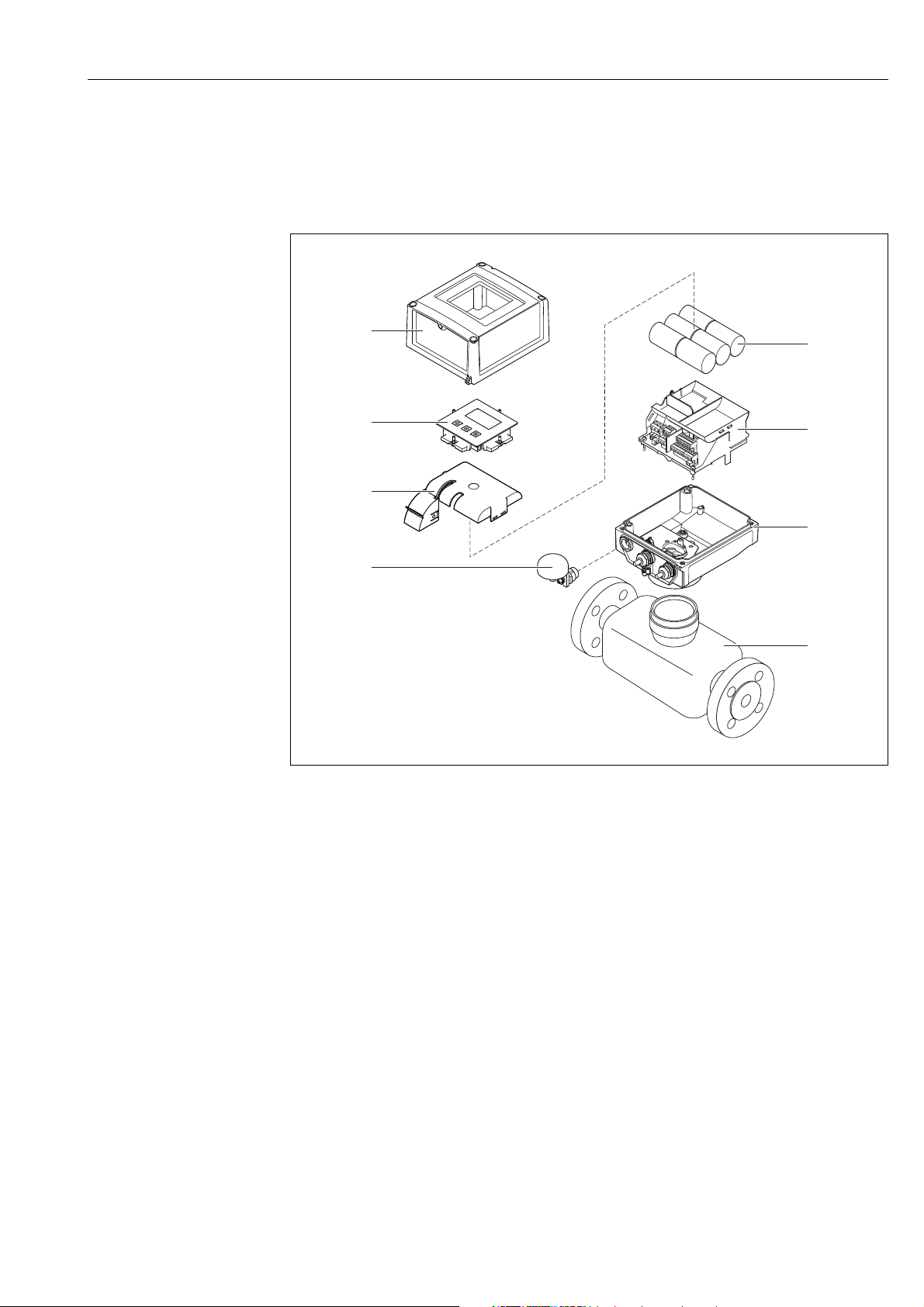
3 Product description
3.1 Product structure
A0016254
Fig. 1: Primary components of the measuring device
1Transmitter housing cover
2 Display and operating module
3 Battery cover
4 GSM antenna
5Batteries
6 Electronics board carrier incl. battery compartment
7Transmitter housing
8Sensor
Endress+Hauser 11
Page 12
Incoming acceptance and product identification Proline Promag W 800
1
+
2
1
+
2
4 Incoming acceptance and product
identification
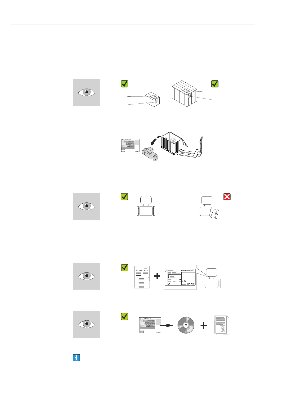
4.1 Incoming acceptance
!
"
A0013696 A0013843
Is the order code in the delivery note (1) identical to the order code on the product
sticker (2)?
A0013695
Note!
The lithium-thionyl chloride high-power batteries are provided in a separate package.
Pay attention to the occupational safety instructions when handling batteries → 9.
A0013696 A0013698
Goods undamaged?
Caution!
If batteries are damaged, comply strictly with the hazardous material regulations described
in the safety data sheet. You can request the safety data sheet from your Endress+Hauser
Sales Center.
A0013696 A0013699
A0013696 A0013697
Do the data on the nameplate correspond to the order data on the delivery note?
CD-ROM available with technical documentation and documents?
If you have answered "no" to one of the questions above:
Contact your Endress+Hauser Sales Center.
12 Endress+Hauser
Page 13
Proline Promag W 800 Incoming acceptance and product identification
i
Patents
i
Material:
Tm:
Ext. ord. cd.:
Order Code:
Ser.No.:
Date:
21
3
4
5
6 7
8
9
10
11
13
12
14
15
4.2 Product identification
It is possible to identify the measuring device in the following ways:
• Using the nameplate specifications
• Using the order code with a breakdown of the device features on the delivery note
• By entering the serial number on the nameplates into the W@M Device Viewer
(www.endress.com/deviceviewer): All the information pertaining to the measuring device
is displayed.
For an overview of the scope of the Technical Documentation provided, please see:
• The "Additional standard documentation on the device" (→ 7) and
"Supplementary device-dependent documentation" (→ 7) sections.
•The W@M Device Viewer: Enter the serial number on the nameplate
(www.endress.com/deviceviewer)
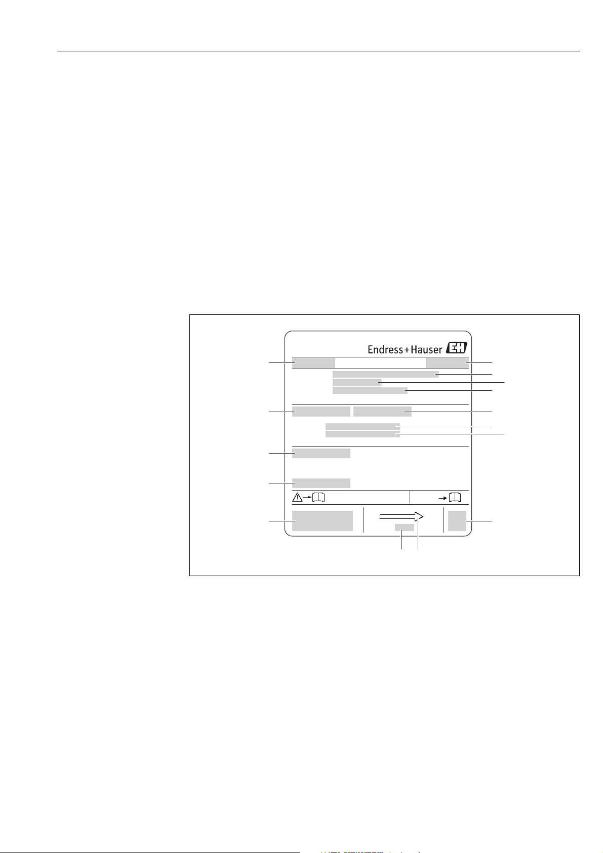
4.2.1 Nameplates
Sensor
Fig. 2: Example of sensor nameplate
1 Name of sensor
2 Place of manufacture
3Order code
4 Serial number (Ser.No.)
5 Extended order code (Ext. ord. co.)
6 Nominal diameter of the sensor
7 Test pressure of the sensor
8 Fluid temperature range
9 Measuring tube lining and electrodes material
10 Degree of protection: e.g. IP, NEMA
11 Permitted ambient temperature (T
12 2-D matrix code
13 CE mark, C-tick
14 Flow direction
15 Date of manufacture: year-month
Endress+Hauser 13
A0017186
)
Page 14
Incoming acceptance and product identification Proline Promag W 800
1
Promag W 800 DN100
Environmental Class: E1/M2
2
Q3: 250 m3/h
3
Q3 / Q1: 160
4
Medium Temp.: 0…+50 °C
5
Tamb: –25…+40 °C
1259 ATLab–I13–001
M13
6
Order code:
i
Ext. ord. cd.:
Ser. no.:
Patents
i
Date:
2
1
345
9
86 7
10
14 13 12 1115
A0020811
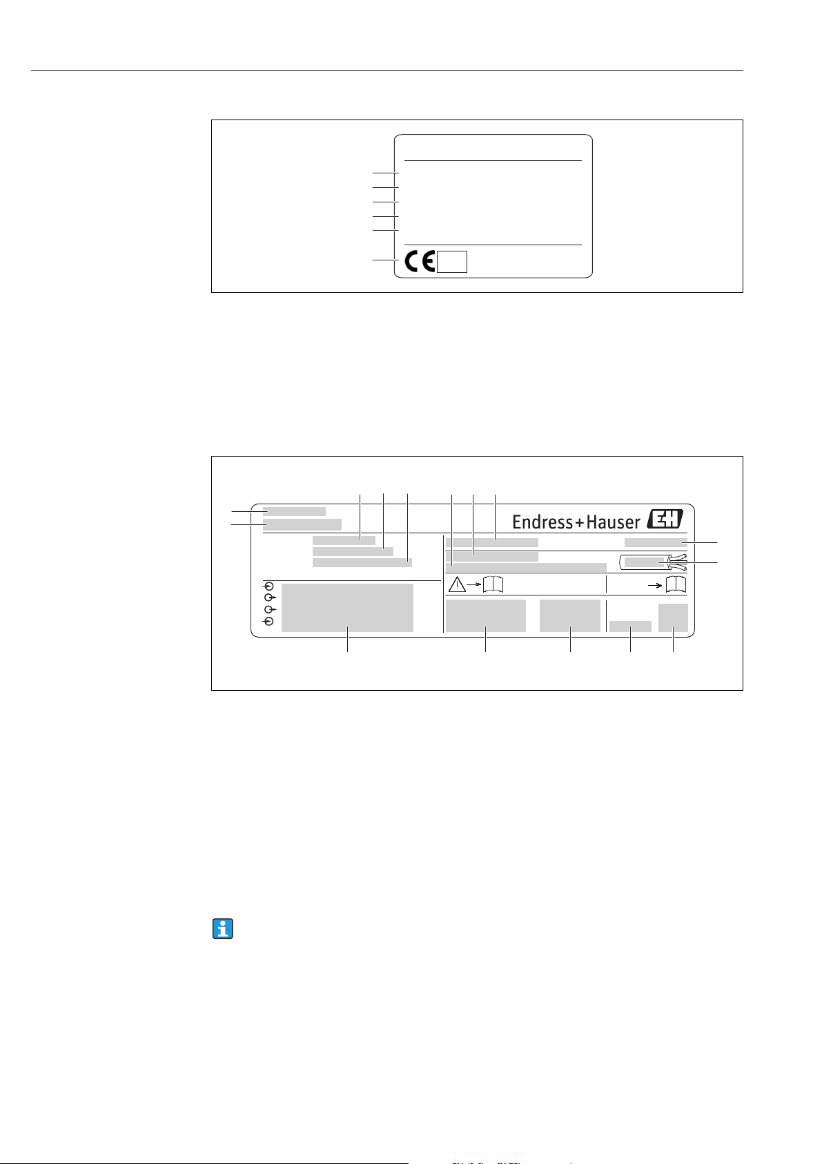
Fig. 3: Additional nameplate for measuring devices subject to legal metrological control (optional) (example)
1 Electromagnetic/mechanical environment class
2 Permanent flowrate Q3
3 Permanent flow ratio Q3/Q1
4 Permitted fluid temperature range
5 Permitted ambient temperature range
6 Conformity marking with CEM mark, year, notified body and number of the EC type-examination certificate
Transmitter
Fig. 4: Example of transmitter nameplate
1 Name of transmitter
2 Place of manufacture
3Order code
4 Serial number (Ser.No.)
5 Extended order code (Ext. ord. co.)
6 Firmware version (FW) and device revision (Dev.Rev.) from factory
7 Permitted ambient temperature range (T
8 FCC-ID (Federal Communications Commission)
9 Degree of protection: e.g. IP, NEMA
10 Permitted temperature range for cables
11 2-D matrix code
12 Date of manufacture: year-month
13 FCC symbol
14 CE mark, C-tick
15 Electrical connection data: e.g. inputs and outputs available, supply voltage
)
Order code
The measuring device is reordered using the order code.
Extended order code
14 Endress+Hauser
• The device type (product root) and basic specifications (mandatory features) are always
listed.
• Of the optional specifications (optional features), only the specifications relating to safety
and hazardous areas are listed (e.g. LA). If other optional specifications are also ordered,
these are indicated collectively using the placeholder symbol "#" (e.g. #LA#).
A0017187
Page 15

Proline Promag W 800 Incoming acceptance and product identification
• If the ordered optional specifications do not include any safety and approval-related
specifications, they are indicated by the placeholder symbol "+" (e.g. 5W8B50–
AACCCAAD2S1+).
4.2.2 Symbols on the device
Symbol Meaning
"Warning" indicates an action or procedure which, if not performed correctly,
#
Warning!
A0011199
A0011194
can result in injury or a safety hazard. Comply strictly with the instructions and
proceed with care.
Protective ground connection
A terminal which must be connected to ground prior to establishing any other
connections.
Reference to documentation
Refers to the corresponding device documentation.
Endress+Hauser 15
Page 16
Storage, transport and disposal of packaging Proline Promag W 800
5 Storage, transport and disposal of packaging
5.1 Storage conditions
Note the following when storing the device:
• Store in the original packaging to protect against impact.
• Do not remove protective covers or protection caps mounted on process connections.
They prevent mechanical damage to the sealing surfaces and fouling in the measuring
pipe.
• Protect from sunlight to avoid impermissibly high surface temperatures.
• Choose a storage location where moisture does not collect in the measuring device. This
will help prevent fungus and bacteria infestation which can damage the liner.
• Store in a dry, dust-free atmosphere.
• Do not store outdoors.
• Storage temperature → 114.
• Also be mindful of the following when storing the batteries:
– Avoid any short-circuiting of the battery poles.
– The storage temperature should preferably be 21 °C (70 °F).
– Store in a dry, dust-free atmosphere that is not subject to large fluctuations in
temperature.
– Protect from sunlight.
– Do not store near heaters.
#
"
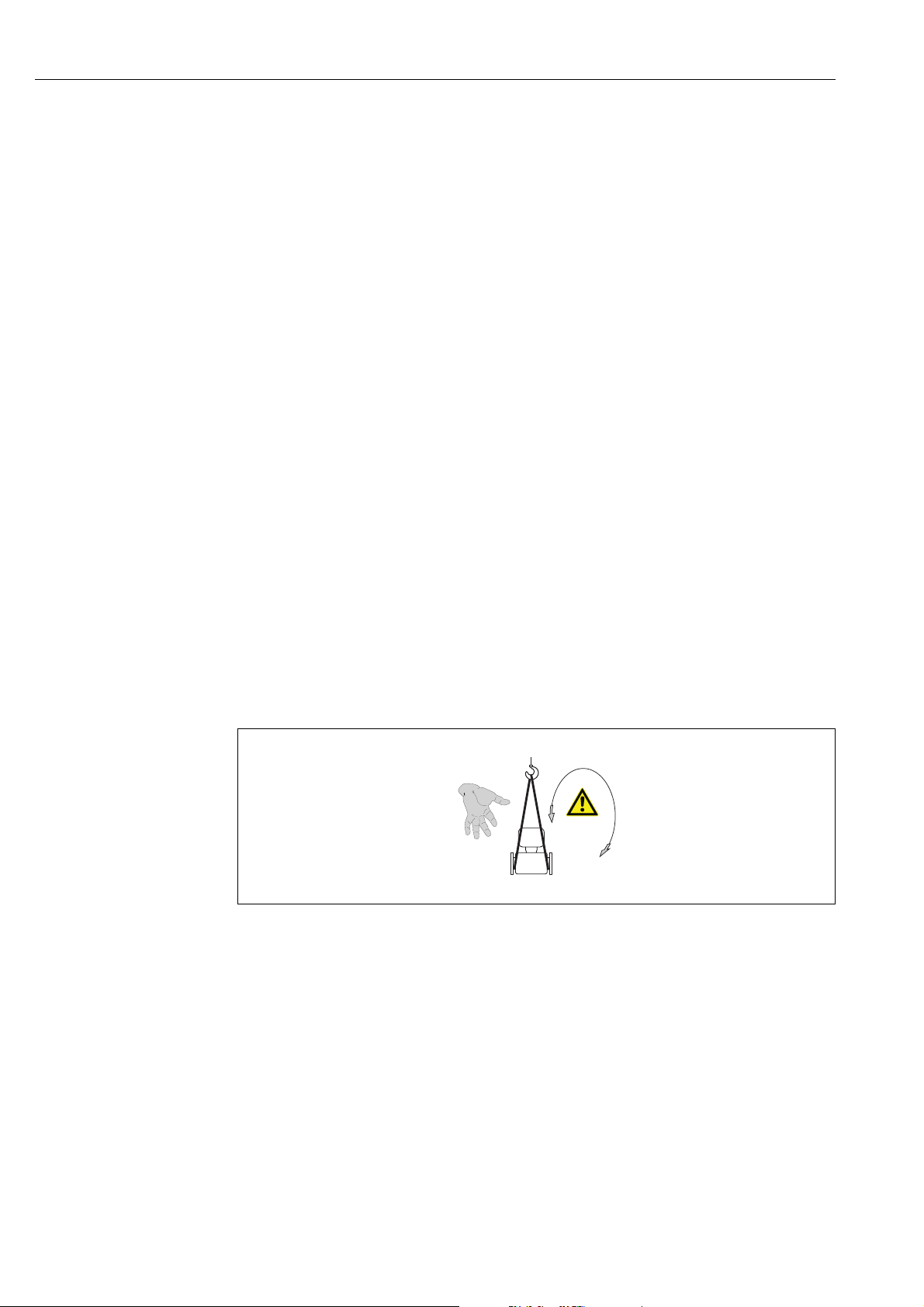
5.2 Transporting the product
Warning!
Risk of injury if the measuring device slips.
The center of gravity of the measuring device is higher than the points around which the
webbing slings are slung.
• Secure the measuring device so that it does not turn around its axis or slip.
A0015606
Fig. 5: Risk of injury if the measuring device slips when transporting sensors
Caution!
Note the following when transporting the device:
• Transport the measuring device to the measuring point in its original packaging.
• Do not remove protective covers or protection caps mounted on process connections.
They prevent mechanical damage to the sealing surfaces and fouling in the measuring
pipe.
• Pay attention to the weight information on the packaging (adhesive label).
• Observe the transportation instructions on the adhesive label on the electronics
compartment cover.
• Do not lift the measuring device by the transmitter housing or the connection housing of
the remote version.
• Lifting tool
– Use webbing slings (avoid chains as these could damage the housing).
16 Endress+Hauser
Page 17

Proline Promag W 800 Storage, transport and disposal of packaging
– For wood crates, the floor structure enables these to be loaded lengthwise or broadside
using a
forklift.
• Using the webbing slings, lift the measuring device by the process connections, not by the
transmitter housing.
5.3 Disposing of the packaging
All the packaging material is environmentally friendly and 100 % recyclable:
• Measuring device secondary packaging:
Polymer stretch wrap that meets the requirements of EU Directive 2002/95/EC (RoHS).
•Packaging
– Wooden crate: treated in accordance with standard ISPM 15,
which is confirmed by the IPPC logo affixed to the crate.
or
– Cardboard: in accordance with European Directive 94/62/EC on packaging and
packaging waste;
recyclability is confirmed by the Resy symbol affixed to the packaging.
• Seaworthy packaging (optional):
Wooden crate, treated in accordance with standard ISPM 15, which is confirmed by the
IPPC logo affixed to the crate.
• Carrier and fastening material:
– Plastic disposable pallet
– Plastic straps
– Plastic adhesive strips
• Filler material: paper pads
Endress+Hauser 17
Page 18
Installation Proline Promag W 800
h
h
2
1
6Installation
6.1 Installation conditions
No special measures such as supports are necessary. External forces are absorbed by the
construction of the device.
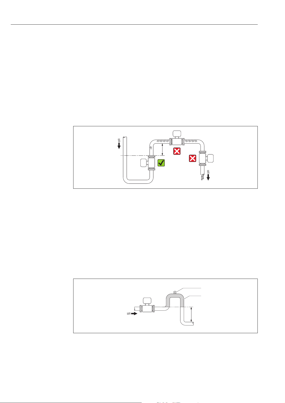
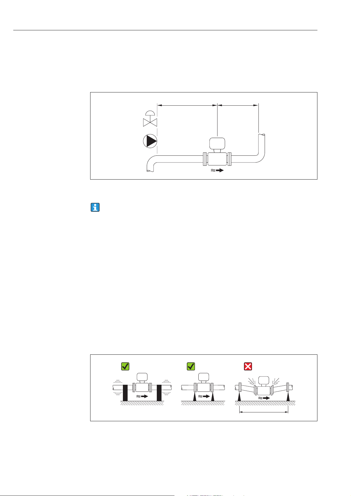
6.1.1 Mounting position
Mounting location
Preferably install the sensor in an ascending pipe, and ensure a sufficient distance (
2 × DN) to the next pipe elbow.
A0017061
Fig. 6: Selecting the mounting location
To prevent measuring errors from gas bubbles accumulating in the measuring tube, avoid
the following mounting locations in the pipe:
• Highest point of a pipeline
• Directly upstream of a free pipe outlet in a down pipe
Installation in down pipes
Install a siphon or a vent valve downstream of the sensor in down pipes whose length
h 5 m (16.4 ft), (→ 7). This precaution is to avoid low pressure and the consequent risk
of damage to the lining of the measuring tube. This measure also prevents the system losing
prime, which could cause air pockets.
Information on the lining's resistance to partial vacuum can be found on → 116.
A0017064
Fig. 7: Measures for installation in a down pipe
1Vent valve
2Pipe siphon
hLength of down pipe, h
18 Endress+Hauser
5 m (16.4 ft)
Page 19
Proline Promag W 800 Installation
³ 5 x DN
³ 2 x DN
Installation in partially filled pipes with a gradient
Partially filled pipes with gradients necessitate a drain-type configuration.
Caution!
"
Risk of solids accumulating.
• Do not install the sensor at the lowest point in the drain.
• It is advisable to install a cleaning valve.
A0017063
Fig. 8: Installation in a partially filled pipe
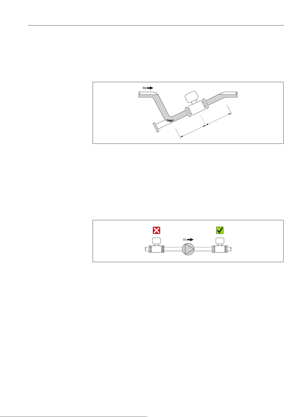
If using pumps
• If pumps are used, do not install the sensor on the intake side of a pump.
This precaution is to avoid low pressure and the consequent risk of damage to the lining
of the measuring tube. Information on the lining's resistance to partial vacuum can be
found on → 116.
• If reciprocating, diaphragm or peristaltic pumps are used,
it might be necessary to install pulse dampers. For information on the measuring system's
resistance to vibration and shock → 115.
Fig. 9: Installation if using pumps
A0015594
Endress+Hauser 19
Page 20
Installation Proline Promag W 800
££3 ( 10)
m (ft)
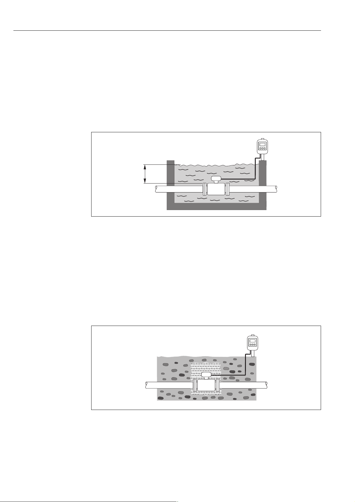
For permanent immersion in water
The fully welded remote version of the measuring device can be immersed permanently in water to a
depth of 3 m (10 ft) or 48 h at 10 m (30 ft).
The measuring device satisfies diverse corrosion
protection categories in accordance with EN ISO 12944. The fully welded design along with
the connection compartment sealing system ensure that moisture cannot enter the
measuring device.
The connecting cables of the remote version can be ordered:
• With pre-terminated cables that are already connected to the sensor.
• Optionally: With pre-terminated cables, where the cables are connected by the customer
onsite (incl. tools for sealing the connection compartment).
A0017296
Fig. 10: Installation for permanent immersion in water
For buried applications
The fully welded remote version of the measuring device can be used for buried applications.
The measuring device satisfies the certified corrosion protection Im3 in accordance with
EN ISO 12944. It can be used directly underground without the need for additional
protective measures. The device is installed in accordance with the usual regional
installation regulations (e.g. EN DIN 1610).
The connecting cables of the remote version can be ordered:
• With pre-terminated cables that are already connected to the sensor.
• Optionally: With pre-terminated cables, where the cables are connected by the customer
onsite (incl. tools for sealing the connection compartment).
Fig. 11: Installation for buried applications
20 Endress+Hauser
A0017298
Page 21
Proline Promag W 800 Installation
A
A
1
2
3
2
Orientation
An optimum orientation position helps avoid gas and air accumulations and deposits in the
measuring tube.
Vertical orientation
Vertical orientation is optimal in the following scenarios:
• For self-emptying piping systems.
• For sludge containing sand or stones where the solids tend to settle at the bottom.
A0015591
Fig. 12: Vertical orientation
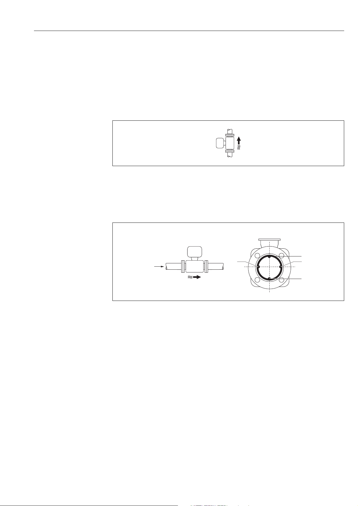
Horizontal orientation
The measuring electrode plane should be horizontal in the case of horizontal orientation.
This prevents brief insulation of the two measuring electrodes by entrained air bubbles.
A0016260
Fig. 13: Horizontal orientation
1 EPD electrode for the detection of empty pipes (not supported by the transmitter)
2 Measuring electrodes used for measuring signal pick up and empty pipe detection (EPD). An EPD alarm is triggered if there
is no fluid between electrodes.
3 Reference electrode for potential equalization
Endress+Hauser 21
Page 22
Installation Proline Promag W 800
5 × DN³
³ 2 × DN
L
Inlet and outlet runs
If possible, install the sensor upstream from fittings such as valves, T-pieces, elbows, etc.
Observe the following inlet and outlet runs in order to meet accuracy specifications:
•Inlet run 5 × DN
•Outlet run 2 × DN
A0016275
Fig. 14: Inlet and outlet runs
No special requirements must be observed at the inlet and outlet runs to keep within
the in-service maximum permissible errors for custody transfer.
6.1.2 Environmental and process-specific requirements
Ambient temperature range
→ 114
Pressure tightness
→ 116
Vibrations
In the event of strong vibrations: support and fix the pipe and sensor.
Caution!
"
If vibrations are too severe, we recommend the sensor and transmitter be mounted
separately. Information on resistance to vibration and shock can be found on → 115.
Fig. 15: Measures to prevent vibration of the device (L > 10 m (33 ft))
A0016266
22 Endress+Hauser
Page 23
Proline Promag W 800 Installation
100
10
0.5
d / D
[mbar]
0.6 0.7 0.8 0.9
1 m/s
2 m/s
3 m/s
4 m/s
5 m/s
6 m/s
7 m/s
8 m/s
1
D
d
max. 8°
Corrosive environment
The fully welded remote version of the measuring device can be immersed permanently in corrosive
(saline) environments
. The measuring device satisfies the certified corrosion protection in
accordance with EN ISO 12944 C5M. The fully welded design along with the varnish finish
ensure that the device can be used in saline environments.
6.1.3 Special installation
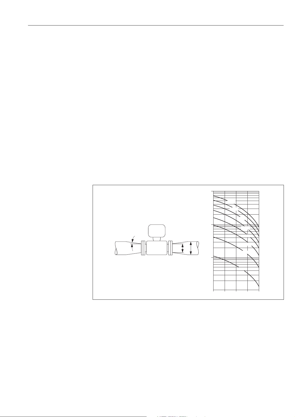
Adapters
Suitable adapters to DIN EN 545 (double-flange reducers) can be used to install the sensor
in larger-diameter pipes.
The resultant increase in the rate of flow improves measuring accuracy with very slowmoving fluids. The nomogram shown here can be used to calculate the pressure loss caused
by reducers and expanders.
!
Note!
The nomogram only applies to liquids of viscosity similar to water.
Determining the pressure loss:
1. Calculate the ratio of the diameters d/D.
2. From the nomogram read off the pressure loss as a function of flow velocity
(downstream from the reduction) and the d/D ratio.
A0016359
Fig. 16: Pressure loss due to adapters
Nominal diameter and flow rate
The diameter of the pipe and the flow rate determine the nominal diameter of the sensor.
Therefore, please note the following:
!
• The optimum velocity of flow is between 2 and 3 m/s (6.5 to 9.8 ft/s).
• Match the velocity of flow (v) to the physical properties of the fluid:
– v < 2 m/s (6.5 ft/s): for abrasive fluids
– v > 2 m/s (6.5 ft/s): for fluids producing buildup
Note!
If it is necessary to increase the flow velocity:
Use adapters to reduce the nominal diameter of the sensor → 23.
Endress+Hauser 23
Page 24

Installation Proline Promag W 800
Recommended flow
Nominal diameter Recommended flow
[mm] [in] Min./max. full scale value (v 0.5 or 10 m/s)
25 1" 15 to 295 dm³/min 4 to 80 gal/min
32 – 25 to 485 dm³/min 7 to 130 gal/min
40 – 40 to 755 dm³/min 10 to 200 gal/min
50 2" 60 to 1180 dm³/min 16 to 320 gal/min
65 – 100 to 2000 dm³/min 28 to 530 gal/min
80 3" 150 to 3020 dm³/min 40 to 800 gal/min
100 4" 240 to 4750 dm³/min 65 to 1200 gal/min
125 – 370 to 7400 dm³/min 100 to 1900 gal/min
150 6" 32 to 640 m³/h 142 to 2800 gal/min
200 8" 58 to 1135 m³/h 250 to 4900 gal/min
250 10" 90 to 1800 m³/h 390 to 7700 gal/min
300 12" 130 to 2500 m³/h 570 to 11000 gal/min
!
Note!
For service subject to legal metrological control the approved flow values apply → 94.
Connecting cable
In order to ensure measuring accuracy, comply with the following instructions when
installing a remote version:
• Fix the cable run or route it in an armored conduit. Cable movements can falsify the
measuring signal especially in the case of low fluid conductivities.
• Route the cable well clear of electrical machines and switching elements.
• Ensure potential equalization between sensor and transmitter, if necessary.
• The maximum connecting cable length is 20 m (35.6 ft).
GSM/GPRS antenna
Check the signal strength of the mobile communications network before mounting the
antenna → 37.
Display protection
To ensure that the optional display protection can be easily opened, maintain the following
minimum head clearance: 350 mm (13.8 in)
24 Endress+Hauser
Page 25

Proline Promag W 800 Installation
6.2 Installing the measuring device
6.2.1 Sensor installation
Required mounting tools
For flange and other process connections:
• Bolts, nuts, seals, etc. These items are not included in the scope of supply and must be
supplied by the customer.
• Appropriate mounting tools
Installing the sensor
Mount the sensor between the pipe flanges.
In doing so, please note the following:
• Required screw tightening torques → 25.
• If using ground disks:
Comply with the Installation Instructions provided with the ground disks.
Mounting the seals
Caution!
"
Risk of short circuit!
Do not use electrically conductive sealing compounds such as graphite! An electrically
conductive layer could form on the inside of the measuring tube and short-circuit the
measuring signal.
Comply with the following instructions when installing seals:
• For hard rubber lining: additional seals are always required.
• For polyurethane lining: generally additional seals are not required.
• For DIN flanges: only use seals according to EN 1514-1.
• Make sure that the seals do not protrude into the piping cross-section.
Mounting the ground cable
Comply with the following instructions when installing the ground cable:
• Comply with the information on potential equalization and detailed mounting instructions
for the use of ground cables on → 43
• If necessary, you can order special ground cables for potential equalization as an accessory
(→ 106).
Screw tightening torques for mounting the sensor
Please note the following:
• The tightening torques listed below are for lubricated threads only.
• Tighten the screws uniformly and in diagonally opposite sequence.
• Overtightening the screws will deform the sealing faces or damage the seals.
• The tightening torques listed below apply only to pipes not subjected to tensile stress.
Tightening torques for:
•EN (DIN) → 26
•ASME → 26
•AS → 27
•JIS → 27
Endress+Hauser 25
Page 26

Installation Proline Promag W 800
Promag W tightening torques for EN (DIN)
Nominal diameter EN (DIN) Max. tightening torque [Nm]
[mm] Pressure rating [bar] Threaded fasteners Hard rubber Polyurethane
25 PN 40 4 × M 12 – 15
32 PN 40 4 × M 16 – 24
40 PN 40 4 × M 16 – 31
50 PN 40 4 × M 16 48 40
65* PN 16 8 × M 16 32 27
65 PN 40 8 × M 16 32 27
80 PN 16 8 × M 16 40 34
80 PN 40 8 × M 16 40 34
100 PN 16 8 × M 16 43 36
100 PN 40 8 × M 20 59 50
125 PN 16 8 × M 16 56 48
125 PN 40 8 × M 24 83 71
150 PN 16 8 × M 20 74 63
150 PN 40 8 × M 24 104 88
200 PN 10 8 × M 20 106 91
200 PN 16 12 × M 20 70 61
200 PN 25 12 × M 24 104 92
250 PN 10 12 × M 20 82 71
250 PN 16 12 × M 24 98 85
250 PN 25 12 × M 27 150 134
300 PN 10 12 × M 20 94 81
300 PN 16 12 × M 24 134 118
300 PN 25 16 × M 27 153 138
* Designed acc. to EN 1092-1 (not to DIN 2501)
Promag W tightening torques for ASME
Nominal diameter ASME Max. tightening torque
Pressure rating [lbs] Threaded fasteners Hard rubber Polyurethane
[mm] [in] [Nm] [lbf · ft] [Nm] [lbf · ft]
25 1" Class 150 4 × ½" – – 7 5
25 1" Class 300 4 × 5/8" – – 8 6
50 2" Class 150 4 × 5/8" 35 26 22 16
50 2" Class 300 8 × 5/8" 18 13 11 8
80 3" Class 150 4 × 5/8" 60 44 43 32
80 3" Class 300 8 × ¾" 38 28 26 19
100 4" Class 150 8 × 5/8" 42 31 31 23
100 4" Class 300 8 × ¾" 58 43 40 30
150 6" Class 150 8 × ¾" 79 58 59 44
150 6" Class 300 12 × ¾" 70 52 51 38
200 8" Class 150 8 × ¾" 107 79 80 59
250 10" Class 150 12 × 7/8" 101 74 75 55
300 12" Class 150 12 × 7/8" 133 98 103 76
26 Endress+Hauser
Page 27

Proline Promag W 800 Installation
Promag W tightening torques for AS
Nominal diameter AS Max. tightening torque [Nm]
[mm] Pressure rating Threaded fasteners Hard rubber Polyurethane
80 Table E 4 × M 16 49 –
80 PN 16 4 × M 16 49 –
100 Table E 8 × M 16 38 –
100 PN 16 4 × M 16 76 –
150 Table E 8 × M 20 64 –
150 PN 16 8 × M 20 52 –
200 Table E 8 × M 20 96 –
200 PN 16 8 × M 20 77 –
250 Table E 12 × M 20 98 –
250 PN 16 8 × M 20 147 –
300 Table E 12 × M 24 123 –
300 PN 16 12 × M 24 103 –
Promag W tightening torques for JIS
Nominal diameter JIS Max. tightening torque [Nm]
[mm] Pressure rating Threaded fasteners Hard rubber Polyurethane
25 20K 4 × M 16 – 19
32 20K 4 × M 16 – 22
40 20K 4 × M 16 – 24
50 10K 4 × M 16 40 33
50 20K 8 × M 16 20 17
65 10K 4 × M 16 55 45
65 20K 8 × M 16 28 23
80 10K 8 × M 16 29 23
80 20K 8 × M 20 42 35
100 10K 8 × M 16 35 29
100 20K 8 × M 20 56 48
125 10K 8 × M 20 60 51
125 20K 8 × M 22 91 79
150 10K 8 × M 20 75 63
150 20K 12 × M 22 81 72
200 10K 12 × M 20 61 52
200 20K 12 × M 22 91 80
250 10K 12 × M 22 100 87
250 20K 12 × M 24 159 144
300 10K 16 × M 22 74 63
300 20K 16 × M 24 138 124
Endress+Hauser 27
Page 28
Installation Proline Promag W 800
PH 2
4 x
TX 20
4 x
3.
4 x
SW 7
2.
4.
5.
6.
1.
1.3 Nm
1.5 Nm
3.0 Nm
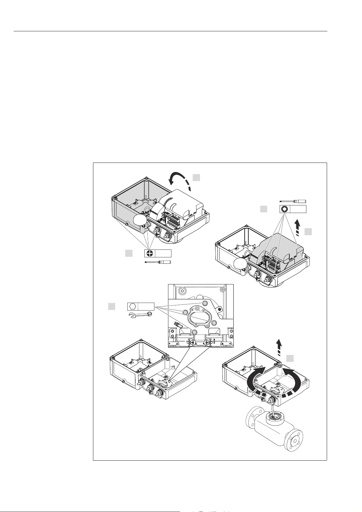
6.2.2 Turning the transmitter housing
1. Release the four screws on the housing cover.
2. Lift the housing cover slightly and tip it to the left.
Two flexible fasteners secure the housing cover to the housing.
3. Release the four screws on the electronics board carrier.
(one screw is located under the folding part of the battery cover).
4. Gently lift up the electronics board carrier until it is possible to access the connection
between the signal cable and the sensor. Disconnect the signal cable from the sensor
and remove the carrier from the transmitter housing.
5. Release the four screws on the transmitter housing.
6. Lift the transmitter housing slightly and turn it to the required position.
Reverse the sequence to install the transmitter housing.
A0017378
Fig. 17: Turning the transmitter housing
28 Endress+Hauser
Page 29
Proline Promag W 800 Installation
149 (5.85)
210.5 (8.29)
=
5.8 (0.23)
mm (in)
18 (0.71) =
14 (0.55)
5.8 (0.23)
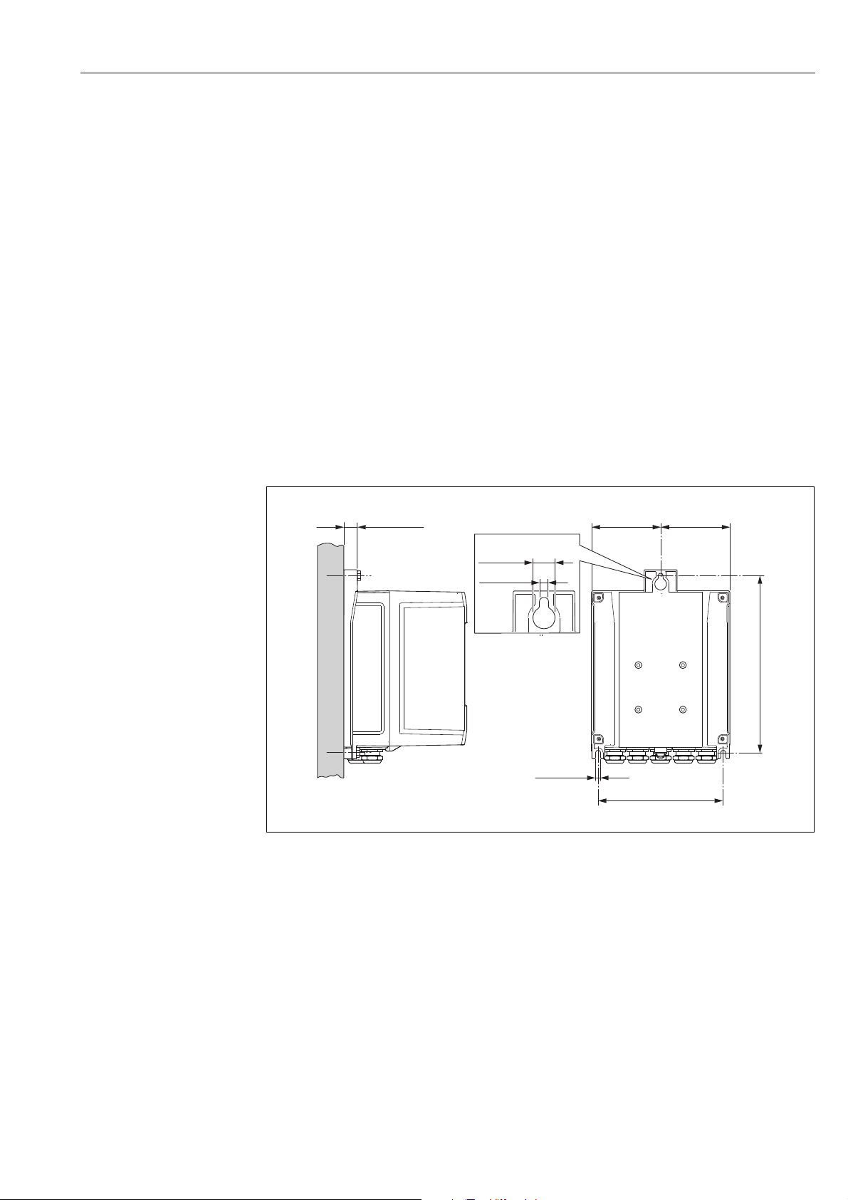
6.2.3 Installing the wall-mount housing
There are various ways of installing the wall-mount transmitter housing:
• Direct wall mounting
• Pipe mounting (with separate mounting kit, accessories)→ 30
Caution!
"
The permitted operating temperature range → 114 may not be exceeded or undershot.
Note the following points:
• Install the measuring device in a shady location. Avoid direct sunlight, particularly in warm
climatic regions.
• The transmitter must be mounted separate from the sensor if both the ambient and fluid
temperatures are high.
Direct wall mounting
1. Drill the holes as illustrated in the graphic.
2. Screw in the securing screws slightly at first.
3. Fit the transmitter housing over the securing screws and mount in place.
4. Tighten the securing screws.
Fig. 18: Direct wall mounting
Endress+Hauser 29
A0016411
Page 30
Installation Proline Promag W 800
ø 20…70
( 0.79…2.75)
ø
mm (in)
PH 2
SW 8
4 x
4 x
~ ~ 6.7)170 (
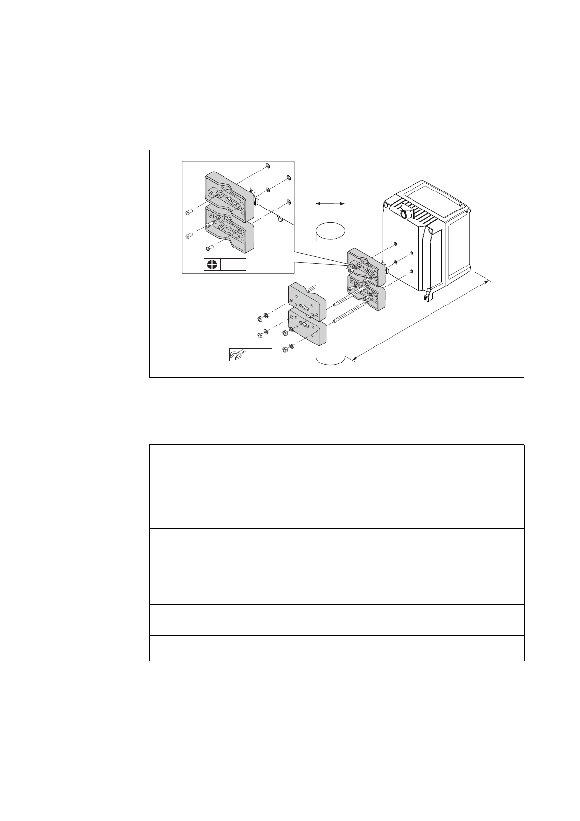
Pipe mounting
The assembly should be performed by following the instructions in the graphic.
Caution!
"
If using a warm pipe, make sure that temperatures do not exceed the permitted ambient
temperature range → 114.
Fig. 19: Pipe mounting (wall-mount housing)
6.3 Post-installation check
Is the measuring device undamaged (visual inspection)?
Does the measuring device meet the specifications of the measuring point?
For example:
• Process temperature → 115
• Process pressure (see the "Material load diagrams" section in the "Technical Information" document")
• Ambient temperature range → 114
• Measuring range → 110
Has the correct orientation been selected for the sensor → 18?
• According to sensor type
• According to fluid temperature
• According to fluid properties (outgassing, with entrained solids)
Does the arrow on the sensor nameplate match the actual direction of fluid flow through the pipe?
Are the measuring point identification and labeling correct (visual inspection)?
Is the device adequately protected from precipitation and direct sunlight?
Have the fastening elements been tightened with the correct tightening torque?
Has the signal strength for the GSM/GPRS modem been checked at the mounting location?
Is the signal strong enough for operation purposes?
A0016412
30 Endress+Hauser
Page 31

Proline Promag W 800 Electrical connection
7 Electrical connection
7.1 Preparing the measuring device
7.1.1 Required mounting tools
• For cable entries: use an appropriate tool.
• For the housing cover: use a Phillips head screwdriver.
• Cable stripper.
• For stranded cables: use a crimper for wire end ferrules.
• To remove cables from terminals: use a slotted screwdriver 3 mm (0.12 in).
7.1.2 Connecting cable requirements
The connecting cables provided by the customer must meet the following criteria:
Electrical safety
According to national regulations.
Cable specification
• Permitted temperature range: –40 to 80 °C (–40 to 176 °F);
Minimum ambient temperature: + 20 K
• A shielded cable is recommended
• Stripped length: 6 mm
• Strand (flexible): 2.5 mm²
• Cable diameter
– With cable glands supplied:
M20 × 1.5 with cable Ø 6 to 12 mm (0.24 to 0.47 in)
– Plug-in screw terminals: core cross-sections 0.5 to 2.5 mm² (20 to 14 AWG)
7.1.3 Connecting cable requirements for the remote version
The connecting cables for the remote version provided by the customer must meet the
following criteria:
Cable specifications
Electrode cable
• 3 × 0.38 mm² PVC cable with common, braided copper shield ( 7 mm) and individually
shielded cores
• Conductor resistance: 50 km
• Capacitance: core/shield: 420 pF/m
• Operating temperature: –20 to +80 °C (–4 to 176 °F)
• Cable cross-section: max. 2.5 mm
Coil current cable
• 2 × 0.75 mm² PVC cable with common, braided copper shield (Ø 7 mm)
• Conductor resistance: 37 km
• Capacitance: core/core, shield grounded: 120 pF/m
• Operating temperature: –20 to +80 °C (–4 to 176 °F)
• Cable cross-section: max. 2.5 mm²
• Test voltage for cable insulation: 1433 V AC r.m.s 50/60 Hz or 2026 V DC
Endress+Hauser 31
Page 32

Electrical connection Proline Promag W 800
1
2
3
4
5
6
7
ab
A0003194
Fig. 20: Cable cross-section
a Electrode cable
b Coil current cable
1Core
2 Core insulation
3 Core shield
4 Core jacket
5 Core reinforcement
6 Cable shield
7 Outer jacket
Reinforced connecting cables
As an option, Endress+Hauser can also deliver reinforced connecting cables with an
additional, reinforcing metal braid.
Use a reinforced connecting cable in the following situations:
• When laying the cable directly in the ground
• Where there is a risk of damage from rodents
• If using the device below IP68 degree of protection
Operation in zones of severe electrical interference
The measuring device complies with the general safety requirements in accordance with
EN 61010-1 and the EMC requirements of IEC/EN 61326.
Caution!
"
Grounding is by means of the ground terminals provided for the purpose inside the
connection housing. Ensure that the stripped and twisted lengths of cable shield to the
ground terminal are as short as possible.
32 Endress+Hauser
Page 33

Proline Promag W 800 Electrical connection
A
B
GND
80 (3.15)
50 (1.97)
18.5 (0.73)
6 (0.24)
100 (3.94)*
mm (inch)
1
2
1
2
1
2
A
B
115 (4.53)*
70 (2.76)
50 (1.97)
10 (0.39)8 (0.31)
mm (inch)
1
A
B
GND
80 (3.15)
50 (1.97)
6 (0.24)
³1 (0.04)
170 (6.69)*
20 (0.79)*
18.5 (0.73)
1
2
2
2
1
A
B
70 (2.76)
50 (1.97)
10 (0.39)
8 (0.31)
160 (6.30)*20 (0.79)*
1
1
1
7.1.4 Preparing the electrode and coil current cable
Terminate the electrode and coil current cables as shown in the figure below (Detail A).
Fit the fine-wire cores with wire end ferrules (Detail B).
Caution!
"
Please note the following when terminating the cables:
• In the case of electrode cable, make sure that the ferrules do not touch the wire shield on
the sensor side. Minimum distance = 1 mm (exception “GND” = green cable).
• In the case of coil current cables, insulate one core of the three-core wire at the level of the
core reinforcement. You only require two cores for the connection.
TRANSMITTER
Electrode cable Coil current cable
A0016477 A0016479
SENSOR
Electrode cable Coil current cable
1 = Red ferrules, Ø 1.0 mm
2 = White ferrules, Ø 0.5 mm)
* Stripping only for reinforced cables
A0016488 A0016489
Endress+Hauser 33
Page 34

Electrical connection Proline Promag W 800
123
1234
5
7.1.5 Preparing the measuring device
• Remove any dummy plugs.
Caution!
"
Poor sealing in the housing can affect the operational reliability of the measuring device.
Use suitable cable glands that correspond to the degree of protection.
If the measuring device is supplied without cable glands, provide appropriate cable glands
for the connecting cable that comply with IP protection requirements.
• If the measuring device is supplied with cable glands, observe the cable specifications.
Cable entry
Compact version Remote version
#
!
Fig. 21: Cable entries for the compact version
1 Connection terminal for GSM antenna (optional)
2 External power supply (optional)
3 Inputs/outputs
A0016457
Fig. 22: Cable entries for the remote version
1 Connection terminal for GSM antenna (optional)
2 External power supply (optional)
3 Inputs/outputs
4 Coil current cable
5Electrode cable
A0016458
7.2 Connecting the measuring device
Warning!
• Risk of electric shock!
Switch off the power supply before opening the device. Do not install or wire the device
while it is energized. Failure to comply with this precaution can result in irreparable
damage to the electronics.
• Risk of electric shock!
Connect the protective conductor to the ground terminal on the housing before the power
supply is applied (not necessary if the power supply is galvanically isolated).
• Compare the specifications on the nameplate with the local voltage supply and frequency.
Also comply with national regulations governing the installation of electrical equipment.
Note!
Incorrect connection work can reduce electrical safety!
• Connection work must only be performed by properly trained specialists.
• Observe national regulations governing the installation of electrical equipment.
• Comply with local workplace safety regulations.
34 Endress+Hauser
Page 35

Proline Promag W 800 Electrical connection
17
16 15 14
10
98765
13
12 11
4321
–2+– +1–+
3
7.2.1 Connecting the inputs and outputs
Different production steps are required to commission the measuring device and must
be followed in a set order. Before performing a specific production step, check whether
all the previous steps have been completed accordingly → 67.
1. Open the housing cover.
– Release the four screws with a Phillips head screwdriver.
– Lift the housing cover slightly and tip it to the left. Two flexible fasteners secure the
housing cover to the housing.
2. Push the cable through the cable entry → 34.
To ensure tight sealing, do not remove the sealing ring from the cable entry.
3. Strip the cable ends over 6 mm (0.24 in).
In the case of stranded cables, also attach wire end ferrules.
4. Connect the cables in accordance with the terminal assignment.
When connecting the cable shield to the ground terminal, observe the grounding
concept of the facility. Rigid conductors or flexible conductors with wire end ferrules can
be inserted directly into the terminal without pressing on the wire release.
Fig. 23: Connecting the outputs
1 Output 1
2 Output 2
3 Input 1
Terminal assignment
Inputs Outputs
Terminal Connection Terminal Connection
5 Input 1 (+) 14 Shield, output 1 and 2
6 Input 1 (–) 15 Output 1 (+)
16 Output 2 (+)
17 Output 1 and 2 (–)
5. Fit the cable anchorage and firmly tighten the cable glands.
6. Secure the housing cover.
– Fix the housing cover on the housing.
– Tighten the four screws with a Phillips head screwdriver.
A0017026
Endress+Hauser 35
Page 36

Electrical connection Proline Promag W 800
1
2
3
4
17
16 15 14
10
987 65
13
12 11
4 321
5 743742 41
7.2.2 Connecting the connecting cable in the remote version
Different production steps are required to commission the measuring device and must
be followed in a set order. Before performing a specific production step, check whether
all the previous steps have been completed accordingly → 67.
1. Open the housing cover.
– Release the four screws with a Phillips head screwdriver.
– Lift the housing cover slightly and tip it to the left.
Two flexible fasteners secure the housing cover to the housing.
2. Push the cable through the cable entry → 34.
To ensure tight sealing, do not remove the sealing ring from the cable entry.
3. Strip the cable ends and fit wire end ferrules → 33.
4. Connect the cables in accordance with the terminal assignment.
When connecting the cable shield to the ground terminal, observe the grounding
concept of the facility.
Fig. 24: Connecting the remote version
1 Transmitter terminals
2 Sensor terminals
3 Coil current cable
4 Electrode cable
Terminal assignment
Sensor Transmitter
Terminal Connection Terminal Connection
5 Electrode E1 (brown) 1 Electrode E1 (brown)
7Electrode E2 (white) 2Electrode E2 (white)
4
Reference electrode,
Terminals bridged (green)
37 4 Shield, electrode E2 (white)
41 Coil current cable B2 (black) 11 Reference electrode (green)
42 Coil current cable B1 (black) 12 Coil current cable B2 (black)
3 Shield, electrode E1 (brown)
13 Coil current cable B1 (black)
5. Fit the cable anchorage and firmly tighten the cable glands.
6. Secure the housing cover.
– Fix the housing cover on the housing.
– Tighten the four screws with a Phillips head screwdriver.
A0017027
36 Endress+Hauser
Page 37

Proline Promag W 800 Electrical connection
2.5 mm
£ 20°
£ 20°
7.2.3 Connecting and mounting the GSM/GPRS antennae
Different production steps are required to commission the measuring device and must
be followed in a set order. Before performing a specific production step, check whether
all the previous steps have been completed accordingly → 67.
Checking the signal strength to determine the type of mounting
Check whether and where a sufficiently strong signal of the mobile communications
network is present. A cell phone or the measuring device can be used for this purpose:
• Hold a cell phone, containing a SIM card from the same provider, at the desired antenna
mounting point and read how strong the signal is.
• If the measuring device is already operational (batteries inserted and battery power
switched on → 42), the signal strength can be read:
– On the onsite display by calling up the status of the antenna signal → 49.
– In the operating tool by using the ANTSS parameter to read the signal strength →
164.
If the signal strength 30 %, the antenna must be mounted separately from the measuring
device.
Connecting and mounting the antenna
• Mount the antenna:
– Signal strength > 30 %: mount the antenna on the measuring device → 25.
– Signal strength 30 %: mount the antenna separately from the measuring device →
27.
• Connect the antenna to the measuring device → 26.
Mounting the antenna directly on the measuring device
When mounting, make sure the antenna holder is as vertical as possible!
Fig. 25: Mounting the antenna directly on the measuring device
Connecting the antenna to the measuring device
A0017387
A0017388
Fig. 26: Connecting the antenna
Endress+Hauser 37
Page 38

Electrical connection Proline Promag W 800
³ 77 (3)
mm (in)
³ 75 (2.9)
M12
Mounting the antenna separately from the measuring device
• Mount the antenna as high as possible above the ground.
• Do not mount it beneath metal objects, covers, floors and ceilings.
• Make sure you maintain the minimum distance from walls and ceilings specified in
→ 27.
• Do not extend the antenna cable.
A0016487
Fig. 27: Mounting the antenna separately from the measuring device
7.2.4 Connecting the external power supply (optional)
Preparing the connection
It is possible to power the measuring device directly via an external power supply.
In addition, batteries are to be used as a backup if the power supply fails and to operate the
GSM/GPRS module.
Possible combinations:
Ordered feature
"Power supply"
5W8B**-***J*********
5W8B**-***K*********
If the measuring device is powered via an external power supply, energy from the batteries
is not used. In such instances, the measuring device can work with maximum measured
value acquisition cycles (Prof./ MPROF parameter → 135).
To ensure the device continues measuring if the external power supply fails, a battery is used
as the backup power supply at the B1 terminal → 40.
The external power supply only supports measuring operation. Additional batteries must be
inserted at the B3 terminal for communication via the GSM/GPRS modem → 40.
Power
supply
100 to 240 V AC
12 to 60 V DC
100 to 240 V AC
12 to 60 V DC
Number of
batteries
1 back-up battery
1 back-up battery
3 batteries for GSM/GPRS module
The batteries are not charged if an external power supply is used.
The current state of charge of the batteries can be read on the onsite display or in the
BATTS parameter → 164.
38 Endress+Hauser
Page 39

Proline Promag W 800 Electrical connection
17
16 15 14
10
98765
13
12 11
4321
N– L+
)
)
12
3
Measuring device requirements
• Integrate the measuring system into the potential equalization system → 43.
• The power supply line must be equipped with an external protection for overload current
(fuse or automatic circuit breaker).
• The measuring device must have a suitably labeled and easy-to-reach ON/OFF switch.
Power supply and power supply unit requirements
• The power supply must be within the range indicated on the nameplate (Electrical
connection → 112).
• Take the cable specification of the connecting cable into consideration → 112.
• Take the connecting cable requirements into consideration → 112.
Connecting the external power supply
Different production steps are required to commission the measuring device and must
be followed in a set order. Before performing a specific production step, check whether
all the previous steps have been completed accordingly → 67.
1. Open the housing cover.
– Release the four screws with a Phillips head screwdriver.
– Lift the housing cover slightly and tip it to the left. Two flexible fasteners secure the
housing cover to the housing.
2. Fold up the protective cover.
3. Push the cable through the cable entry → 34.
To ensure tight sealing, do not remove the sealing ring from the cable entry.
4. Strip the cable ends over 6 mm (0.24 in).
In the case of stranded cables, also attach wire end ferrules.
5. Connect the cables in accordance with the terminal assignment.
When connecting the cable shield to the ground terminal, observe the grounding
concept of the facility.
Fig. 28: Connecting the external power supply (optional)
Terminal assignment
External power supply
Terminal Connection
1Protective ground
2N –
3L +
A0017028
6. Fold down the protective cover.
7. Fit the cable anchorage and firmly tighten the cable glands.
8. Secure the housing cover.
– Fix the housing cover on the housing.
– Tighten the four screws with a Phillips head screwdriver.
Endress+Hauser 39
Page 40

Electrical connection Proline Promag W 800
B2
B1
B1 B2 B3
B1
B1 B2 B3
B2
B1 B2 B3
B2B1
7.3 Inserting and connecting the batteries
7.3.1 Overview of battery arrangement options
Three battery terminals are available in the measuring device. These terminals are assigned
different uses depending on the number and arrangement of the batteries. B1 and B2 are
the terminals for power supply to the measuring device, B3 is the terminal for the GSM/
GPRS modem.
The measuring device is initially powered by the batteries in terminal B2. If the voltage
supplied by these batteries becomes too low, the measuring device issues a message and
switches automatically to the battery in terminal B1.
If power is supplied to the measuring device externally and the power supply fails, the
battery in terminal B1 acts as a backup power supply.
The GSM/GPRS modem is always powered by the battery in terminal B3.
This is also the case if the measuring device uses an external power supply.
The batteries are not charged if an external power supply is used.
The current state of charge of the batteries can be read on the onsite display or in the
BATTS parameter → 164.
Possible configurations
Configuration 1
Configuration of
batteries
A0017127
Configuration 2
Configuration of
batteries
Connectors
"Power supply" order feature for this configuration: 5W8B**–***F0********
!
Not permitted in custody transfer!
Connectors
"Power supply" order feature for this configuration: 5W8B**–***G0********
Number of
batteries
B 1 1 Backup power supply for the measuring device
B 2 1 Power supply for the measuring device
B 3 – Power supply for the GSM/GPRS modem
Note!
Number of
batteries
B 1 1 Backup power supply for the measuring device
B 2 3 Power supply for the measuring device
B 3 – Power supply for the GSM/GPRS modem
Battery usage
Battery usage
A0017128
Configuration 3
Configuration of
batteries
A0017129
40 Endress+Hauser
Connectors
B 1 3 Backup power supply for the measuring device
B 2 3 Power supply for the measuring device
B 3 – Power supply for the GSM/GPRS modem
"Power supply" order feature for this configuration: 5W8B**–***H0********
Number of
batteries
Battery usage
Page 41

Proline Promag W 800 Electrical connection
B1
B1 B2 B3
B1
B1 B2 B3
B3
B2
B1
B1 B2 B3
B3
Configuration 4
Configuration of
batteries
Configuration 5
Configuration of
batteries
Connectors
B 1 1 Backup power supply for the measuring device
B 2 – Power supply for the measuring device
B 3 – Power supply for the GSM/GPRS modem
Powered via external power
A0017130
"Power supply" order feature for this configuration: 5W8B**–***J0********
Connectors
B 1 1 Backup power supply for the measuring device
B 2 2 Power supply for the measuring device
B 3 3 Power supply for the GSM/GPRS modem
"Power supply" order feature for this configuration: 5W8B**–***HP********
supply
Number of
batteries
Number of
batteries
Battery usage
Power supply for the measuring device
Battery usage
Configuration 6
Configuration of
batteries
A0017131
Connectors
Number of
batteries
Battery usage
B 1 1 Backup power supply for the measuring device
B 2 – Power supply for the measuring device
B 3 3 Power supply for the GSM/GPRS modem
Powered via external power
Power supply for the measuring device
supply
A0017132
"Power supply" order feature for this configuration: 5W8B**–***KP********
Endress+Hauser 41
Page 42

Electrical connection Proline Promag W 800
B1 B2 B3
7.3.2 Inserting and connecting the batteries
Different production steps are required to commission the measuring device and must
be followed in a set order. Before performing a specific production step, check whether
all the previous steps have been completed accordingly → 67.
#
"
Warning!
Risk of electric shock!
Switch off the power supply before opening the device.
Caution!
Can damage the electronic of the device!
Only use batteries provided by Endress+Hauser.
1. Open the housing cover.
– Release the four screws with a Phillips head screwdriver.
– Lift the housing cover slightly and tip it to the left. Two flexible fasteners secure the
housing cover to the housing.
2. Remove the battery cover.
– Release the securing screw with a Phillips head screwdriver.
– Turn the battery cover in a slightly clockwise direction to remove it (two guides which
hold the battery cover in position are located on the right-hand side).
3. Insert the batteries.
Place the batteries into the compartment. In doing so, route the battery cables in the
direction of the cable inlet in the battery cover → 30.
If not all the batteries are inserted, the partition plate can be used to prevent any
inserted batteries from becoming dislodged.
Fig. 29: Example of a battery arrangement (configuration 5)
B1 Battery connection to back up the power supply for the measuring device
B2 Battery connection to power the measuring device
B3 Battery connection to power the GSM/GPRS module
4. Connect the batteries.
– Insert the battery cables into the appropriate receptacle → 30.
5. Set the DIP switches → 30.
The following options are available:
– Set the DIP switch to ON to switch on the battery power supply.
If battery power supply is switched on, the red CPU LED flashes → 69 and the
startup sequence appears on the onsite display → 69.
– Set the DIP switch to OFF to switch off the battery power supply.
42 Endress+Hauser
A0016648
Page 43

Proline Promag W 800 Electrical connection
1
B2
B1
B3
B1 B2 B3
ON
12
B1/B2
ON
B3
ON
12
17
16 15 14
10
987 65
13
12 11
4 321
LOCK
CPU
GSM
2
B1 B2 B3
3
ON
12
B1/B2
ON
B3
ON – OFF
B3
B1/B2
4
ON
12
LOCK
ON – OFF
A0017025
Fig. 30: Connecting the batteries, switching on the battery power supply
1 Cable inlet in the battery cover
2 Receptacles for terminals B1 and terminals B2 and B3
3 DIP switch (ON/OFF) for switching the batteries on and off:
- Switch 1: terminals B3
- Switch 2: terminals B1 and B2
4 DIP switch (ON/OFF) to disable the controls of the local display
#
6. Secure the battery cover.
– Route the battery cables in the direction of the cable inlet in the battery cover → 30.
– Fit the battery cover in place. In doing so, position the guides into the slots in the
battery cover.
– Tighten the securing screw with a Phillips head screwdriver.
– Fold down the protective cover for the external power supply.
7. Secure the housing cover.
– Fix the housing cover on the housing.
– Tighten the four screws with a Phillips head screwdriver.
Comply with instructions for battery disposal → 108.
7.4 Potential equalization
Warning!
Integrate the measuring system into the potential equalization system.
7.4.1 Potential equalization requirements
Please consider the following to ensure correct measurement:
• The fluid and sensor have the same electrical potential
• Company-internal grounding concepts
• Material and grounding of the pipes
Endress+Hauser 43
Page 44

Electrical connection Proline Promag W 800
7.4.2 Connection examples for potential equalization
Connection example in standard situations
Metal, grounded pipe
A0016315
Fig. 31: Potential equalization via Measuring tube
Connection example in special situations
Metal, ungrounded pipe without liner
This connection method is also to be used when:
• Potential equalization is not customary
• Equalizing currents are present
A0022704
Fig. 32: Potential equalization via ground terminal and pipe flanges
For mounting consider the following:
• Connect both sensor flanges to the particular pipe flange via a ground cable and ground
them.
Ground cable = copper wire, at least 6 mm² (0.0093 in
²
).
• Connect the transmitter or sensor connection housing, as applicable, to ground potential
by me ans of the ground termin al provided for the purpose. For mounting the ground cable:
– Mount the ground cable directly on the conductive flange coating of the sensor with the
flange screws.
For remote version: The ground terminal in the example refers to the sensor and not
to the transmitter.
The required ground cable can be ordered from Endress+Hauser.
44 Endress+Hauser
Page 45

Proline Promag W 800 Electrical connection
1 /
+
–
2 /
2 /
3 /
Plastic pipe or pipe with insulating lining
This connection method is also to be used when:
• Potential equalization is not customary
• Equalizing currents are present
A0016318
Fig. 33: Potential equalization via ground terminal and ground disk
For mounting consider the following:
The ground disks have to be connected to the ground terminal via a ground cable and to the
ground potential. Ground cable = copper wire, at least 6 mm² (0.0093 in²).
For remote version: The ground terminal in the example refers to the sensor and not
to the transmitter.
The required ground cable can be ordered from Endress+Hauser.
Pipe with cathodic protection
This connection method only take place, if both of the following requirements are fulfilled:
• Metal pipe without liner or pipe with electrically conductive liner
• Cathodic protection is integrated in the operator protection
A0016319
Fig. 34: Potential equalization and cathodic protection
1 Isolating transformer power supply
2 Electrically isolated to pipe
3 Capacitor
1. Connect the measuring device potential-free compared to protective earth to the power
supply.
2. Install the measuring device electrically isolated in the pipe.
3. Connect the two flanges of the pipe with a ground cable.
Ground cable = copper wire, at least 6 mm² (0.0093 in²).
4. By connecting the shielding of the signal cables a capacitor has to be used.
For remote version: The ground terminal in the example refers to the sensor and not
to the transmitter.
The required ground cable can be ordered from Endress+Hauser.
Endress+Hauser 45
Page 46

Electrical connection Proline Promag W 800
7.5 Guaranteeing the degree of protection of the measuring device
Caution!
"
Do not loosen the threaded fasteners of the sensor housing, as otherwise the degree of
protection guaranteed by Endress+Hauser no longer applies.
To guarantee the degree of protection of the measuring device → 115.
Perform the following steps after electrical connection:
• Check that the housing seals of the connection and electronics compartment are clean and
fitted correctly. Dry, clean or replace the seals if necessary.
• Tighten all housing screws and screw covers.
• Firmly tighten the cable glands.
• To ensure that moisture does not enter the cable entry, route the cable so that it loops
down before the cable entry ("water trap").
Fig. 35: Cable looped down before the cable entry
• Insert dummy plugs into unused cable entries.
• Notes on measuring devices with IP68 option → 20.
7.6 Post-connection check
Is the measuring device undamaged (visual inspection)?
Do the cables used comply with the requirements?
Do the cables have adequate strain relief?
Are all cable glands installed, firmly tightened and correctly sealed? Cables looped as “water traps”?
Does the supply voltage match the specifications on the transmitter nameplate?
Is the ribbon cable for the display and operating module correctly routed in the housing?
Is the terminal assignment correct?
Is the GSM/GPRS antenna connected correctly?
Is the signal strong enough to establish a connection to a GSM/GPRS network?
Have the batteries been inserted and secured correctly?
Is the DIP switch set to the correct setting?
If power is supplied, is the measuring device ready for operation (the red LED is flashing) and does
information appear on the display if an operating key is pressed for >1 second?
Are all housing covers installed and tightened with the correct tightening torque?
A0013960
46 Endress+Hauser
Page 47

Proline Promag W 800 Operating options
1
24 5
3
8 Operating options
8.1 Overview of operating options
A0016602
Fig. 36: Overview of operating options
1 Local operation of the measuring device
2 Computer with Config 5800 operating tool
3 FXA 291 service interface (connected to computer via USB port and to measuring device via service interface)
4 Cell phone (wireless via SMS)
5 Computer (wireless via mail)
8.2 Structure and function of the operating menu
8.2.1 Structure of the operating menu
• The measuring device has a main menu with different parameter groups.
These parameter groups correspond to different applications or areas of the measuring
device.
• The parameter groups contain the various parameters that belong to the individual
applications or areas of the measuring device.
• The desired setting or option for the measuring device configuration is made in the
individual parameters.
• Some parameters cannot be modified since they are only used to display values or
information, or can only be modified by users with a higher access authorization level →
51.
Main menu with
parameter groups
1 - Sensor ND ND: mm 00050
Sens.Type Sens.type = 000
Parameters Configuration
KA KA: mm +01.000
… …
2 - Scales … …
3 - Measure
4 - Alarms
!
…
Note!
For an overview of the main menu and all the parameters available, see → 124 ff.
Endress+Hauser 47
Page 48

Operating options Proline Promag W 800
2011/07/01
BOARD T.:
ANT.SIG:
19 : 45
+25°C
[ OFF ]
ALARM 1/3:
B3 LOW
8.2.2 Operating concept
The parameters in the measuring device have different access levels. The parameters can be
modified by all users or just by certain user groups depending on the associated access level.
Some parameters can only be accessed via the Config 5800 operating tool.
• The parameters can be accessed via:
– The local operation of the measuring device → 48
– The Config 5800 operating tool → 51
• The majority of the parameters can be configured without any restrictions (up to Level 2).
Special service-specific and device-specific parameters (Level 3 and above) can only be
modified by Endress+Hauser Service staff.
For further information on access authorization, see → 51.
8.3 Access to the operating menu via the onsite display
8.3.1 Operating elements and display area
The measuring device has three operating elements and one display area.
Fig. 37: Operating elements and display area of the measuring device
Operating elements
Key Operation Meaning
Press briefly
(<1 second)
Press and hold
(>1 second)
Press briefly
(<1 second)
Press and hold
(>1 second)
Press briefly
(<1 second)
Press and hold
(>1 second)
• Scroll up through the parameters
• Scroll up through the options
• Increase the numerical values
• If several alarms are active: scroll up through the alarm list
• Scroll down through the parameters
• Scroll down through the options
• Decrease the numerical values
• If several alarms are active: scroll down through the alarm list
• Change the display area or the display values
• Move the cursor to the right
• Scroll down through the parameters
• Change the display area or the display values
• Move the cursor to the left
• Scroll up through the parameters
• Select the menu
• Select the parameter
• Confirm the entry, selection
• Exit the current menu
• Return to the main menu
• Return to the display
•Switch display on/off
A0016977
48 Endress+Hauser
Page 49

Proline Promag W 800 Operating options
2011/07/01
BOARD T.:
ANT.SIG:
19 : 45
+25°C
[ OFF ]
ALARM 1/3:
B3 LOW
1
2
3
4
5
0.0
m /h
0 20 40 60 80 100 120
!
..... ..... ..... ..... .... ....
100
75
50
25
0
100
75
50
25
0
m/s0.000
%
10
10
0 %
F S
2
3
4
5
1
3
0.0000
m /h
!
SMART 0.00%
T+ m
1264.6
P+ m
1264.6
1
3
3
3
3
0.0000
m /h
!
SMART 0.00%
T+ m
1264.6
P+ m
.0
2
4
5
6
3
3
3
0.0000
!
SMART 0.00%
T–
145.6
P–
145.6
0.0000
!
1
m /h
3
m
m
3
3
3
0.0000
!
SMART 0.00%
T–
145.6
P–
.0
0.0000
!
2
4
5
6
m /h
3
m
m
3
3
0.0000
!
SMART 0.00%
TN
1119.0
PN
1119.0
1
m /h
3
m
m
3
3
3
0.0000
!
SMART 0.00%
TN
1119.0
PN
.0
2
4
5
6
m /h
3
m
m
3
3
0.0000
m /h !
4
3
1
2
3
( ) B1:
[ ]
1
( ) B3:
[ ]
3
( ) B2:
[ ]
2
Display area
Several measured value and status views are available in the display area.
Users can switch between the individual views using the T key → 50.
Views Meaning
1. Date and time
2. Temperature of electronics board
3. Status of antenna signal
4. Number of alarms (scroll through the alarm list via the V operating
key → 48)
A0016981
A0016982
A0020991
A0020992
A0020993
5. Description of displayed alarm
1. Alarm status
2. Flow value with numeric representation (incl. unit)
3. Flow value with line and bar graph representation
4. Flow value (0 to 100 %) tracked as chart
5. Flow velocity including unit
Note!
!
F (fast) + S (slow) = Filter
1. Alarm status
2. Flow value with numeric representation (incl. unit)
3. Profile of measured value acquisition → 135
4. Full scale value in %
5. Totalizer, positive (incl. unit)
6. Totalizer, positive (incl. unit)
1. Alarm status
2. Flow value with numeric representation (incl. unit)
3. Profile of measured value acquisition → 135
4. Full scale value in %
5. Totalizer, negative (incl. unit)
6. Totalizer, negative (incl. unit)
1. Alarm status
2. Flow value with numeric representation (incl. unit)
3. Profile of measured value acquisition → 135
4. Full scale value in %
5. Totalizer net (balance) (incl. unit)
6. Totalizer net (balance) (incl. unit)
1. Flow value with numeric representation (incl. unit)
2. Bar graph full scale value in %
3. Flow value unit
4. Alarm status
1)
A0016986
1. State of charge of battery in terminal B1
2. State of charge of battery in terminal B2
3. State of charge of battery in terminal B3
A0016987
1) T+ and P+, T- and P- as well as TN and PN have each the same values. It is e.g. possible to reset P+, P- as well as PN periodically to 0, while the
values T+, T- as well as TN are preserved.
Endress+Hauser 49
Page 50

Operating options Proline Promag W 800
2011/07/01
BOARD T.:
ANT.SIG:
19 : 45
+25°C
[ OFF ]
ALARM 1/3:
B3 LOW
0.0
g/s
0 20 40 60 80 100 120
!
..... ..... ..... ..... .... ....
100
75
50
25
0
100
75
50
25
0
m/s 0.000
%
10
10
0 %
F S D
0.0000
kg/s
!
MAX LIFE 0.00%
T+ m
0
P+ m
999999
123
( ) B3:
[ ]
( ) B1:
[ ]
2011/07/01
BOARD T.:
ANT.SIG:
19 : 45
+25°C
[ OFF ]
ALARM 1/3:
B3 LOW
71
0.0000
kg/s
!
MAX LIFE 0.00%
TN
–2999999
PN
–2000000
0.0000
m /h !
56
0.0000
kg/s
!
MAX LIFE 0.00%
T–
2999999
P–
2999999
4
3
3
m
m
3
3
m
m
3
3
3
( ) B2:
[ ]
8.3.2 Changing the views in the display area
Users can switch between the individual views using the T key → 48.
A0016988
Fig. 38: Changing the views
Locking the view toggle function
1. Select the desired display using the T key.
2. Use the Y key to switch to the main menu.
3. Switch to parameter group "8-DISPLAY", go to the "Disp.lock" parameter and select the
option "ON" → 150.
8.3.3 Changing parameters
1. Press and hold the Y key for 2 seconds and then release.
The device leaves the standby mode and the measured value or status display screen
Ã
appears.
2. Press Y once.
The main menu is displayed.
Ã
Note!
!
The Quick Start menu is displayed during initial commissioning or if the "Quick start"
parameter (QSTME → 150) is set to ON (default value). In such instances, use V to
select the "Main menu" option and enter the main menu.
3. Press V to select the desired parameter group.
4. Press Y to confirm the selection.
The parameter group is called up.
Ã
5. Press V to select the desired parameter.
6. Press Y to confirm the selection.
The parameter is displayed.
Ã
7. Use V to change the option selected or the value.
Note!
!
In the case of some parameters, it is possible to make several settings within the
parameter (example Tot1MU → 133).
8. Press Y to confirm the selection.
The option or value selected is accepted.
Ã
For information on access authorization to parameters, see → 51.
50 Endress+Hauser
Page 51

Proline Promag W 800 Operating options
8.3.4 User roles and related access authorization
Access to parameters
The parameters in the measuring device have different access levels.
The majority of the parameters can be configured without any restrictions (up to Level 2).
Level 2 parameters can be protected by an individual password → 62.
Special service-specific and device-specific parameters (Level 3 and above) can only be
modified by Endress+Hauser Service staff. These parameters can be read by every user,
however. The parameters have a gray background in the description of the device
parameters (see Appendix).
If a user attempts to change a service-specific or device-specific parameter, the prompt
"L3 Code =0..." appears on the onsite display. If using the Config 5800 operating tool,
the error message "5:Access error" appears on the display.
Access to parameters that are only available via the Config 5800 operating tool
The parameters in parameter groups 0 "Quick-Start" to 11 "Internal Data" can be configured
both via local operation and via the parameter menu of the operating tool.
The parameters in the parameter groups "GRPS data", "Auxiliary cmds" and "Process data" can
only be configured via the parameter menu of the operating tool → 58.
Parameter groups that are used to configure or establish communication via the GSM/
GPRS modem are only available via the Config 5800 operating tool.
Custody transfer (optional):
After putting the device into circulation or after sealing the device, operation via the onsite
display, via the Config 5800 software operating tool or via GSM/GPRS is only possible to a
limited extent.
8.3.5 Enabling and disabling the keypad lock
The keypad lock allows you to disable access to the entire operating menu via local
operation. This makes it no longer possible to navigate through the operating menu or
modify the values of individual parameters. Only the measured values on the measured
value display can be read off. The keypad is locked using the DIP switches on the electronics
board → 89.
8.4 Access to the operating menu via the operating tool
8.4.1 Config 5800 operating tool
Config 5800 is a software operating tool which is used to configure and operate the
Promag 800 measuring device. The measuring device does not support any other operating
tools.
Function scope
• Access to all the measuring device parameters:
– Via the user interface integrated in the operating tool
– Via the parameter menu
• Configuring/establishing measuring device communication via GSM, mail etc.
These parameters are only available via the parameter menu of the operating tool.
• Operation of the measuring device.
• Saving or exporting data records (parameters, events etc.).
Endress+Hauser 51
Page 52

Operating options Proline Promag W 800
• Saving or loading the configuration of the measuring device.
How to acquire the Config 5800 operating tool
• CD-ROM (in the scope of delivery)
• www.endress.com Download
8.4.2 Installing the Config 5800 operating tool
PC oder laptop requirements
• Intel® i486® or Pentium
• Microsoft Windows 2000®, Windows XP®, Windows Vista® or Windows 7
• 32 MB RAM
• 10 MB free space on the hard drive
• CD-ROM drive
• USB port
Installing the Config 5800 operating tool
processor
!
Note!
• If an earlier version of the software is already installed:
Uninstall the earlier version before installing the latest version of the software.
• Install all the software components.
1. Close all the applications.
2. Insert the CD-ROM into the drive.
3. Follow the instructions in the dialog boxes.
8.4.3 Connecting the laptop to the measuring device
Hardware and software required
• Commubox FXA291 service interface (USB version)
• Laptop with Config 5800 operating tool installed → 51
Connecting the laptop
1. Open the housing cover of the measuring device.
– Release the four screws with a Phillips head screwdriver.
– Lift the housing cover slightly and tip it to the left.
Two flexible fasteners secure the housing cover to the housing.
2. Switch on the measuring device → 69.
The measuring device must be switched on and successfully started (the CPU LED
is flashing (red)) before you connect the Commubox FXA291 → 69).
3. Connect the Commubox FXA291.
– Via the USB port on the laptop
– Via the service interface on the measuring device.
52 Endress+Hauser
Page 53

Proline Promag W 800 Operating options
2
3
1
1
A0016587
Fig. 39: Connecting a laptop to the service interface via Commubox FXA291
1CDI interface of the measuring device
2 Commubox FXA291 (USB version)
3 Laptop with Config 5800 operating tool installed
4. Start the Config 5800 operating tool and establish communication with the measuring
device → 53.
8.4.4 Starting the Config 5800 operating tool
Start the operating tool by clicking on the Config 5800 icon on the desktop.
8.4.5 Establishing communication between Config 5800 and the
measuring device
A0020989
Fig. 40: Config 5800 user interface
1 Fading in/out the information/settings for the interface
Endress+Hauser 53
Page 54

Operating options Proline Promag W 800
A0020990
Fig. 41: Information/settings for the interface
!
Note!
If communication is not established successfully, the COM port must be determined via the
Device Manager of the connected laptop and then assigned manually:
1. Via the Device Manager, determine the COM port used for the connected "USB
Commubox FXA291 Serial Port".
A0016990
Fig. 42: Example of the Device Manager
2. From the picklist, select the COM port found.
54 Endress+Hauser
Page 55

Proline Promag W 800 Operating options
1
3
2
6
5
4
7
12 4
356
8.4.6 Config 5800 user interface
A0020979
Fig. 43: Config 5800 user interface
Sections of the user interface:
1 Device information display (name of the measuring device, firmware version, E+H serial number)
2 Parameter menu, display field and input box
3Password entry box
4 Integrated user interface (corresponds to the onsite display)
5Function menu
6 Save or load configuration and parameters (laptop
7 Load event or process data from the data logger (SD card) (measuring device
measuring device)
laptop)
Function menu
A0020980
Fig. 44: Config 5800 user interface: function menu
1 Function to display and hide the integrated user interface
2 Function to display and hide the parameter menu
3 Function to update the parameter menu
4 Function to display and hide the information and settings relating to the interface
5 Function to synchronize the measuring device with the system time of the laptop
6 Function to adjust the size of the individual windows
Endress+Hauser 55
Page 56

Operating options Proline Promag W 800
1
1
2
Adjusting the user interface
The user interface can be adjusted individually using the mouse. However, please note that
areas can be covered over and might not be available directly in the adjusted view. The
changes are retained when the operating tool is restarted.
A0020981
Fig. 45: Adjusting the user interface
1 Function to adjust the size of the individual windows
8.4.7 Selecting parameters
The following options for selecting device parameters are available in the operating tool:
• Parameter selection via the integrated user interface (corresponds to the onsite display)
• Parameter selection via the tree structure view
Selecting parameters via the integrated user interface
The operating tool has an integrated user interface. All the functions, views and parameters
of this user interface correspond to the onsite display.
A0016995
Fig. 46: Config 5800 user interface: integrated user interface
1 Integrated user interface (corresponds to the onsite display)
2 Button: display and hide the integrated user interface
(the button is located around the function menu on the user interface → 55)
56 Endress+Hauser
Page 57

Proline Promag W 800 Operating options
DelEsc
Selecting parameters
Parameters are selected and the device parameters configured in the integrated user
interface via the following keys on the computer keyboard:
Key Meaning
• Scroll up through the parameters
Arrow
up
Arrow
down
Arrow
right
• Scroll up through the options
• Increase numerical values
• If several alarms are active: scroll up through the alarm list
• Scroll down through the parameters
• Scroll down through the options
• Decrease numerical values
• If several alarms are active: scroll down through the alarm list
• Change the display format or the display values
• Move the cursor to the right
• Scroll down through the parameters
Arrow
left
Enter
Escape
or
Delete
• Change the display format or the display values
• Move the cursor to the left
• Scroll up through the parameters
• Select the menu
• Select the parameter
•Confirm the entry, selection
• Exit the current menu
• Return to the main menu
• Return to the display
Endress+Hauser 57
Page 58

Operating options Proline Promag W 800
4
1
2
3
5
6
Selecting parameters in the tree structure view
The tree structure displays all the parameter groups currently available and the associated
parameters.
A0020982
Fig. 47: Config 5800 user interface: parameter menu as tree structure
1Parameter menu
2View box
3Input box
4 Function to list the parameters/main menu alphabetically
5 Key to clear view box
6 Button: display and hide parameter menu
(the button is located around the function menu on the user interface → 55)
Selecting parameters
• The parameters in the parameter group are displayed by double-clicking a parameter
group or by clicking [+].
• The substructure of the parameter is displayed by double-clicking a parameter or by
clicking [+].
• The set value or the configuration options of the parameter are displayed in the left display
area by double-clicking a parameter. The following options are available:
– Parameter with "?": the parameter value currently set is displayed.
– Parameter with "=?": the possible configuration options of the parameter are displayed.
– Parameter "=": the parameter settings can be edited.
58 Endress+Hauser
Page 59

Proline Promag W 800 Operating options
A0016997
Fig. 48: Example: parameter signs for the PDIMV parameter
Clearing entries in the view box
All the queries and entries made are displayed in the view box. These entries can be deleted
via the "Clear text results" button.
Endress+Hauser 59
Page 60

Operating options Proline Promag W 800
2011/07/01
BOARD T.:
ANT.SIG:
19 : 45
+25°C
[ OFF ]
ALARM 1/3:
B3 LOW
0.0
g/s
0 20 40 60 80 100 120
!
..... ..... ..... ..... .... ....
100
75
50
25
0
100
75
50
25
0
m/s 0.000
%
10
10
0 %
F S D
MAIN MENU
1 - Sensor
2 - Scales
3 - Measure
4 - Alarms
5 - Inputs
6 - Outputs
7 - Communication
2 - SCALE
Fs =
Temp. u. meas. =
Tot1MU =
Pls1 =
Tpls1 =
Sg =
t/s 0.0050
°C
g 00001
g 1000.0
ms 0111.0
kg/dm 01.00000
Pls1= g 1000.0
2 - SCALE
Fs =
Temp. u. meas. =
Tot1MU =
Pls1 =
Tpls1 =
Sg =
t/s 0.0050
°C
g 00001
g 1000.0
ms 0111.0
kg/dm 01.00000
2 - SCALE
Fs =
Temp. u. meas. =
Tot1MU =
Pls1 =
Tpls1 =
Sg =
t/s 0.0050
°C
g 00001
g 1000.0
ms 0111.0
kg/dm 01.00000
Esc
Esc
Esc
Esc
Esc
Esc
...
...
2 - Scale
Pls1= kg 0000.8
g 1000.0
kg 1000.01
kg 1000.0
0
g
g 1000.0
kg
kg 0000.0
0
kg 0000.0
9
kg 0000.0
8
4 x
3
3
3
8.4.8 Changing parameters
Changing parameters via the integrated user interface
Example: changing the pulse value from 1000 g to 0.8 kg
!
Note!
The Quick Start menu is displayed during initial commissioning or if the "Quick start"
parameter (QSTME → 150) is set to ON (default value).
In such instances, select the "Main menu" option to enter the main menu.
Changing parameters via the parameter menu
Changing a numerical value in a parameter
Example: changing the nominal diameter from DN 25 to DN 125
60 Endress+Hauser
1. Double-click the "Sensor" parameter group.
The parameters in the "Sensor" parameter group are displayed.
Ã
2. Double-click the "PDIMV" parameter (nominal diameter).
The substructure of the parameter opens.
Ã
3. Double-click "PDIMV?".
The current value for the nominal diameter is displayed in the view box: 25 (mm)
Ã
4. Double-click "PDIMV=?".
The possible input range is displayed in the view box: 0 <>10000 (mm)
Ã
A0016998
Page 61

Proline Promag W 800 Operating options
4.3.
5.
6.
1. 2.
5. – Double-click "PDIMV=".
The input box shows the prompt: PDIMV=
Ã
– In the input box, enter the value 125 after "PDIMV=" (PDIMV=125).
6. Press F to confirm the value entered.
The correct entry PDIMV=125 is confirmed in the view box: 0:OK.
Ã
Fig. 49: Example for PDIMV parameter: changing the nominal diameter from DN 25 to DN 125
!
!
Note!
If no value is entered in the input box and F is pressed, the value "0" is accepted.
Changing an option selected in a parameter
In the case of picklists, the value corresponding to the option must be entered.
Example: changing the language
1. Double-click the "Display" parameter group.
2. Double-click the "LLANG" parameter (language).
3. Double-click "LLANG?".
4. Double-click LLANG=?
5. – Double-click "LLANG="
6. Press F to confirm the value entered.
7. Double-click "LLANG?".
Note!
If the value entered is invalid, the error message "2:PARAM ERR" appears on the display.
The parameters in the "Display" parameter group are displayed.
Ã
The substructure of the parameter opens.
Ã
The current language is displayed in the view box "2:FR" (French)
Ã
The picklist appears in the view box "0:EN, 1:IT, 2:FR, 3:SP"
Ã
"LLANG=" appears in the input box.
Ã
– In the input box, enter the value 0 after "LLANG=" (LLANG=0).
The correct entry is confirmed in the view box: 0:OK.
Ã
The new language is displayed in the view box "0:EN" (English)
Ã
A0016999
Endress+Hauser 61
Page 62

Operating options Proline Promag W 800
1
8.4.9 Access authorization
All the parameters in the operating tool are assigned a certain level. Level 2 parameters can
be protected by an password in order to prevent unauthorized persons from modifying the
device configuration.
Parameter levels
• Level 1 parameters:
Read and write access without entering a password
• Level 2 parameters:
Write access can be protected by defining a password; read access without password entry.
• Level 3 parameters and higher (special service-specific and device-specific parameters):
Write access only for Endress+Hauser Service staff; read access without password entry.
These parameters have a gray background in the parameter description → 130. The
message "L3 Code =0..." or "5:ACCESS ERR." appears on the display if a user attempts to
change these parameters.
Assigning a password for Level 2 parameters
Assigning a password via local operation
!
Enter a numerical password, with a maximum of six digits, in the "L2 code" parameter →
158.
The following options are available:
• Password = numeric six-digit password: write access only by entering a password
• Password = 000000 (factory setting): write access without entering a password
Assigning a password via the Config 5800 operating tool
Enter a numerical password, with a maximum of six digits, in the "L2ACD" parameter →
158.
The following options are available:
• Password = numeric six-digit password: write access only by entering a password
• Password = 000000 (factory setting): write access without entering a password
Note!
If you forget the password, it is not possible to simply reset the password!
Contact your Endress+Hauser Sales Center if you lose or forget the password.
Access to parameters with password assigned
Access to parameters via the onsite display and integrated user interface of the operating tool
When a Level 2 parameter is accessed, the user is prompted to enter the password.
The parameter can be changed as soon as the password is entered.
Access to parameters via the parameter menu of the operating tool
When a Level 2 parameter is accessed via the parameter menu of the operating tool → 58,
an error message appears in the view box. The password must first be entered in the "Set
code level" input box before you can change Level 2 parameters. The password is displayed
in the ACODE parameter → 163 and saved until the next time it is changed via "Set code
level".
Fig. 50: Config 5800 user interface: entering a password to access Level 2 parameters via the parameter menu
1Input box
62 Endress+Hauser
A0017000
Page 63

Proline Promag W 800 Operating options
3
2
1
4
5 6
7
8
Enter the value 000000 in the "Set code level" input box to reset access.
8.4.10 Saving and loading the configuration and parameters
The configuration and the parameters of the measuring device can be saved as a file on a
laptop via the operating tool. Conversely, a file containing a configuration and the
parameters can be uploaded from a laptop to the measuring device via the operating tool.
The file is saved as a text file and can be opened in a text editor.
This function is only available once the system times have been synchronized.
Synchronization via the button in the function menu (No. 5 → 55).
Fig. 51: Config 5800 user interface: saving or loading the configuration and parameters
1 Displays the directory path of the saved files
2 Load the configuration or parameters
3 Save the configuration (measuring device
4 Save the parameters (measuring device
5 Option for opening a file after saving it
6 Opens the directory with the saved files
7 Option for opening a file after loading it
8 Change the file directory for saving and loading
laptop); the file name can be changed if necessary
laptop); the file name can be changed if necessary
Configuration file
Possible applications
• Save the configuration of the measuring device to restore the settings to a known
configuration (e.g. after replacing the electronics or changing the configuration).
• Transfer the configuration to other measuring devices in order to use the same
configuration.
• Offline configuration of the measuring device in order to make changes directly in the .txt
file and then upload the new configuration to the measuring device.
Caution!
"
When uploading the configuration file to a measuring device, make sure that the data in the
parameters are suitable for the measuring device. Values such as the nominal diameter,
calibration factor, zero point etc. must be appropriate for the measuring device. If a
configuration file with incorrect values is uploaded to a measuring device, this can result in
incorrect measurements and damage the measuring device!
A0020983
Using a configuration file
1. Save the configuration of a measuring device to a file via "Save Configuration".
Change the file name where necessary.
Recommended file naming convention: xx_DNyy.txt
(xx = serial number of the measuring device, yy = nominal diameter of the measuring
device)
Endress+Hauser 63
Page 64

Operating options Proline Promag W 800
2. Change the configuration file where necessary, e.g. if uploading to other measuring
devices:
– Leave parameters that are to be used for other measuring devices in the file and
change them where necessary
– Delete parameters that are not used for other measuring devices
– Adapt or delete parameters with device-specific values (e.g. nominal diameter,
calibration factor etc.)
A0017002
Fig. 52: Configuration file
3. Save the changes made in the configuration file.
4. Upload the configuration file to a measuring device via "Load a Configuration or
Function List".
Caution!
"
Before loading the configuration file make sure that the serial number and the nominal
diameter information in the configuration file matches the information in the
measuring device.
– Serial number: parameter SRNUM (Config 5800) → 159
– Nominal diameter: parameter ND (onsite display)/PDVIM (Config 5800) → 130
The values of the parameters in the file are transferred to the measuring device.
Ã
All other measuring device parameters remain unchanged.
Ã
Parameters as list
Possible applications
For displaying a list of the parameters of the measuring device to get an overview of all the
parameters available in the measuring device. The list displays the parameter names of the
onsite display and the Config 5800 operating tool.
8.4.11 Loading event and process data from the data logger (SD card)
Event data (access to the measuring device, alarms etc.) and process data (measured values,
status of the measuring device etc.) can be saved on a data logger in the measuring device
(2 GB SD card).
If data logging is enabled (Acquisition parameter, DLOGE → 152), the process data are
recorded and written to a file every day. It is possible to specify the time and the recording
interval for saving the process data → 171.
Parameter group "9 Data logger" is used to specify which process data (parameters) are saved
→ 151.
The event and process data can be uploaded from the data logger (SD card) to a laptop.
64 Endress+Hauser
Page 65

Proline Promag W 800 Operating options
3
2
1
4
5 6
7
8
2012\01\05\EVENTS.TXT
Cancel
OK
2012\23\04\EVENTS.TXT
Cancel
OK
A0020984
Fig. 53: Config 5800 user interface: reading data from data logger (SD card)
1 Displays the directory path of the saved files
2 Load file with event data (measuring device
3 Selection of the time frame
4 Load file with process data (measuring device
5 Read file
6 Option for opening the file immediately after saving
7 Opens the directory with the saved files
8 Respecify the folder in which the files are saved/loaded
laptop)
laptop)
Loading event data from the data logger (SD card)
1. Click the "Read Events from SD" button.
An input window opens.
Ã
2. Via the date in the file name, specify the day for which the event data should be loaded
→ 54. Then press "OK" to confirm.
The file with the event data is loaded in .TXT format.
Ã
An error message is displayed if no event data are available for the selected date.
Fig. 54: Via the file name, specify the day for which the event data should be loaded.
Example: if the file name is changed from 01\05 to 23\04, the event data from April 23, 2012 are loaded
3. Click the "View PC file folder" button.
The directory in which the file was saved opens.
Ã
4. Select and open the event data file.
The file is opened in .TXT format.
Ã
If the "Show File" option is enabled (→ 53, No. 4), the file with the event data is
automatically opened once it is loaded.
5. Evaluate the event data.
Loading process data from the data logger (SD card)
A0017318
Endress+Hauser 65
1. Click the "Read Logger from SD" button.
An input window opens.
Ã
2. Via the date in the file name, specify the day for which the process data should be
loaded. Then press "OK" to confirm.
The file with the process data is loaded in .CSV format.
Ã
An error message is displayed if no process data are available for the selected date.
Page 66

Operating options Proline Promag W 800
2012\01\05\DATA_LOG.CVS
Cancel
OK
2012\23\04\DATA_LOG.CVS
Cancel
OK
A0017319
Fig. 55: Via the file name, specify the day for which the process data should be loaded.
Example: if the file name is changed from 01\05 to 23\04, the process data from April 23, 2012 are loaded
3. Click the "View PC file folder" button.
The directory in which the file was saved opens.
Ã
4. Select and open the process data file.
The file is opened in .CSV format.
Ã
If the "Show File" option is enabled (→ 53, No. 4), the file with the process data
is automatically opened once it is loaded.
5. Import the .CSV file into a spreadsheet program, such as MS Excel. When importing the
file, pay attention to the delimiter used (comma or semicolon).
The delimiter used in the .CSV can be configured in the Separator parameter,
DLFSC → 155.
6. Evaluate the process data. For the file structure, see → 85.
The imported file with the process data does not have any headers. If the process
data are loaded and evaluated more frequently, it can be helpful to add headers
manually to the file. In this way, this file can always be used as an import template
since the structure (columns used → 85) is always identical.
66 Endress+Hauser
Page 67

Proline Promag W 800 Commissioning
9 Commissioning
9.1 Commissioning with the GSM/GPRS modem
Prerequisites for commissioning the measuring device:
• The measuring device has been installed and the GSM/GPRS antenna connected. All the
criteria of the post-installation check are met → 30.
• Wiring is completed. Batteries are inserted, external power supply is connected (optional).
All the criteria of the post-connection check are met → 46.
9.1.1 Commissioning the measuring device
It is only possible to commission the measuring device with the GSM/GPRS modem
using the Config 5800 operating tool. Not all the parameters required are accessible
via local operation.
1. Insert the SIM card → 68.
2. Connect the laptop via FXA291 to the service interface of the measuring device → 52.
3. Start the Config5800 operating tool → 53.
4. Synchronize the system time between the measuring device and the laptop → 55, →
44 (No. 5)
5. Configure GPRS communication → 72.
6. Configure SMS communication → 70.
7. Configure e-mail communication (sending) → 74.
8. Configure e-mail communication (receiving) → 80.
9. Configure the synchronization time with the server → 80.
10. Make other device-specific settings.
Parameter descriptions → 124 ff.
11. After configuring, disconnect the laptop and FXA291 from the measuring device.
12. Fit the housing cover back on.
9.2 Commissioning without the GSM/GPRS modem
Prerequisites for commissioning the measuring device:
• The measuring device has been installed. All the criteria of the post-installation check are
met → 30.
• Wiring is completed. Batteries are inserted, external power supply is connected (optional).
All the criteria of the post-connection check are met → 46.
9.2.1 Commissioning the measuring device via local operation
1. Switch on the measuring device:
– Via the DIP switch if power is supplied by batteries → 43 (→ 30).
Then fit the housing cover back on.
– Via the external power supply switch if power is supplied externally (optional).
2. Configuration of the measuring device via the onsite display → 51.
Parameter descriptions → 124 ff.
Endress+Hauser 67
Page 68

Commissioning Proline Promag W 800
2
1
9.2.2 Commissioning the measuring device via the Config 5800 operating tool
1. Connect the laptop via FXA291 to the service interface of the measuring device → 52.
2. Start the Config5800 operating tool → 53.
3. Synchronize the system time between the measuring device and the laptop → 55, →
44 (No. 5)
4. Configuration of the measuring device via the Config5800 operating tool → 51.
Parameter descriptions → 124 ff.
5. After configuring, disconnect the laptop and FXA291 from the measuring device.
6. Fit the housing cover back on.
9.3 Inserting the SIM card
A SIM card must be inserted in the measuring device before it can establish wireless
communication.
The SIM card must not be protected by a PIN number. Insert the SIM card into a cellular
phone to check whether it is possible to access the card without entering a PIN number.
If necessary, disable PIN entry for the SIM card via the cellular phone.
1. Open the housing cover.
– Release the four screws with a Phillips head screwdriver.
– Lift the housing cover slightly and tip it to the left.
Two flexible fasteners secure the housing cover to the housing.
2. Insert the SIM card into the slot, aligning the notch on the card so that it is at the bottom
at the front.
A0016594
Fig. 56: SIM card slot on the electronics board
1 Slot on the electronics board
2SIM card
68 Endress+Hauser
Page 69

Proline Promag W 800 Commissioning
FW 5.03.0300
Endress+Hauser
Promag 800
1
Free:
Size:
Cluster:
Buffer:
1979.38
1943.37
32
1056
MB
MB
KB
B
4
2011/07/01
BOARD T.:
ANT.SIG:
19 : 45
+25°C
[ OFF ]
ALARM 1/3:
B3 LOW
6
Set date/time
2012/02/02 00:00
2
Wait . . .
Reading SD cart
information
This will take
some time
3
ERROR 0800
5
B1 B2 B3
ON
12
B1/B2
ON
B3
ON
12
17
16 15 14
10
98765
13
12 11
4321
LOCK
CPU
GSM
1
CPU
GSM
2
9.4 Switching on the measuring device
Once the batteries have been inserted, the measuring device is switched on via the DIP
switch → 43. This applies both to battery-powered operation and for operation with an
optional power supply since the device is already powered via the backup battery B1 in this
case.
#
Warning!
Only switch on the external power supply (optional) once the post-installation and postconnection checks have been performed successfully for the device.
After a successful startup, the onsite display switches automatically from the startup display
screens to the measured value display.
A0017030
Fig. 57: Example: display screens when the measuring device is started
1 Name of measuring device, firmware version
2 Date and time entered via the operating keys (entry also possible at a later date) → 48
3 Reads the information from the SD card
4 Displays the memory capacity and the current settings of the SD card
5 Displays any pending errors→ 99 ff.
6 Displays general information
9.4.1 Meaning of the LEDs
The measuring device is fitted with two light emitting diodes (LEDs) on the electronics
board. Once the measuring device has been switched on the LEDs indicate different states
for the measuring device and the GMS module.
A0017024
Fig. 58: Light emitting diodes on the electronics board
1 LED (blue) for GSM module, is lit when communication is active
2 LED (red) for CPU
LED GSM module (blue) LED CPU (red)
State Meaning State Meaning
Off The GSM module is not switched on, in
the standby mode or is not connected to
Off Not switched on or no power supply
available.
a network.
Lit GSM module is trying to log into the
network.
Flashing
slowly
GSM module is logged into the network
and is waiting for commands.
Flashing The LED flashes for every measured
value acquisition. Frequency of
measured value acquisition → 135.
Endress+Hauser 69
Flashing
quickly
The GSM module is sending or receiving
a file (SMS or e-mail), data transmission
in progress.
Flashing
approx. 1
Hz
One or more alarms are active.
Page 70

Commissioning Proline Promag W 800
9.5 Establishing wireless communication
9.5.1 General notes
It is only possible to configure the parameters that are relevant for wireless communication
via the "Config 5800" operating tool. The parameters required to establish communication
are not available in the onsite display.
9.5.2 Configuring SMS communication
1. In the Config 5800 operating tool, call up the "GPRS data" parameter group and
configure the parameters as described in the following table:
ParametersDescription Options and information on
GPASN (→
162)
GPSSN (→
162)
GPSS2 (→
162)
GPSS3 (→
162)
Telephone number of
the sender (sends SMS to
measuring device)
Telephone number of
the first receiver
(receives SMS from
measuring device).
Telephone number of
the second receiver
(receives SMS from
measuring device).
Telephone number of
the third receiver
(receives SMS from
measuring device).
setting the parameter
• Text entry, max. 19 characters
•No number:
The measuring device can
receive every text message
(SMS) from every number.
• Partial number:
The measuring device can
receive all the text messages
(SMS) that start with the
number entered.
• Complete number:
The measuring device can only
receive text messages (SMS)
from the number entered.
• Text entry, max. 19 characters
• A text message (SMS) is sent
to this telephone number if
errors or alarms occur.
• Text entry, max. 19 characters
• A text message (SMS) is sent
to this telephone number if
errors or alarms occur.
• Text entry, max. 19 characters
• A text message (SMS) is sent
to this telephone number if
errors or alarms occur.
Example Source of
• +41123456789:
receives SMS
from this
number only
• +41123456:
receives SMS
from phone
numbers
+41123456000
0 to
+41123456999
9
+41123456789 Customer
+41123456790 Customer
+41123456791 Customer
information
Customer
2. Send a text message (SMS) to the measuring device with the cellular phone.
The parameters of the measuring device can be queried or modified by text message.
Example: Send the command VTTPV? in an SMS to the measuring device (→ 71).
Make sure that you, as the sender (cellular phone number), are also authorized to
send a text message to the measuring device (GPASN parameter).
3. Check the message inbox of the measuring device.
– Via the integrated user interface → 56:
a. Select parameter group "7 - Communication"
b. Select the "Chk SMS" parameter → 149
c. Use the ESC key to confirm the "EXECUTE?" prompt
– Via the tree structure → 58:
a. Select parameter group "Communication"
b. Select the "SMSCI" parameter → 149
c. Select "SMSCI="
"SMSCI=" appears in the input box
Ã
70 Endress+Hauser
Page 71

Proline Promag W 800 Commissioning
d. Enter the value "1" after "SMSCI=" in the input box (SMSCI=1)
e. Press F to confirm the value entered.
The correct entry is confirmed in the view box: 0:OK.
Ã
4. Check whether SMS communication has been established successfully.
SMS communication has been established successfully if:
– the measuring device has sent a reply message (SMS) to the cellular phone.
– the receipt of the query message (SMS) and the transmission of the reply message
(SMS) have both been logged in the event list.
Example
• The parameters are protected by the password "100000".
• The unit for the temperature is to be changed from °C to °F.
• The totalizer positive total is to be displayed.
User entry: ACODE=100000,TMMUV=1,VTTPV?
In the case of protected parameters with Level 2 status or higher, the ACODE
parameter and the password must be the first element specified.
The individual commands, queries etc. must always be separated by a comma without
a space.
Structure of the query message (SMS)
Query message for the example
Category SMS content Description
Sender (from:) +41 123456789 Cellular phone number of the sender. Check the
Receiver (to:) +41 987654321 Cellular phone number of the measuring device.
Text/content ACODE=100000,TMMUV=1,VTTPV?• Password for access (if password-protected)
GPASN parameter to ensure that the measuring
device is authorized to receive a text message
from this cellular phone number → 70.
• Change the unit for temperature to °F
• Query the totalizer value (positive total)
Structure of the reply message (SMS)
Possible reply message for the example above
Category SMS content Description
Sender (from:) +41 987654321 Cellular phone number of the measuring device.
Receiver (to:) +41 123456789 Cellular phone number of the cellular phone from
which the query message was sent.
Text/content °F,dm3,548.989 Temperature unit, unit and current value of the
totalizer (positive total)
Endress+Hauser 71
Page 72

Commissioning Proline Promag W 800
9.5.3 Configuring general GPRS communication
GPRS communication supported by the mobile communications network provider
The parameters listed below must be configured correctly to ensure that the device can
execute the following functions:
• Send e-mails
• Read e-mails
• Synchronize the system time with a time server (NTP server)
The parameter settings must be requested from the cell phone network provider (GPRS
provider) (e.g. home page or customer service).
Communication cannot be established if the settings are incorrect or incomplete.
The measuring device does not have any default settings.
Communication can only be established via the Config 5800 operating tool
It is only possible to configure the parameters that are relevant for wireless communication
via the "Config 5800" operating tool. The parameters required to establish communication
are not available in the onsite display.
The mobile communications network provider must support GPRS communication (GPRS
data traffic) for communication via e-mail to take place. This must be taken into
consideration when selecting the mobile communications network provider and entering a
mobile communications contract.
Verifying parameter settings with the mobile telecommunications provider
Where necessary check the following GPRS data with your mobile communications network
provider:
Information required to configure GPRS communication
Parameters
(GPRS configuration → 72)
GPAPN Name of the access point to
the mobile communications
network
(APN: access point name)
GPUSR User name for
authentication purposes
GPPSW Password for
authentication purposes
GPAUT Authentication type,
access authentic value
required for the network
provider
Settings in the measuring device
(GPRS data → 164)
Information from your
mobile communications network
provider
1. In the Config 5800 operating tool, call up the "GPRS data" parameter group and
configure the parameters as described in the following table:
Parameters Description Options and information on
GPAPN (→
160)
Name of the access point
to the mobile
communications network
(APN: access point name)
setting the parameter
Text entry, max. 31 characters. gprs.provider.comMobile
Example Source of
information
communications
network
provider
72 Endress+Hauser
Page 73

Proline Promag W 800 Commissioning
Parameters Description Options and information on
setting the parameter
GPUSR (→
161)
GPPSW (→
161)
GPAUT (→
161)
User name for
authentication purposes
Password for
authentication purposes
Authentication type,
access authentic value
required for the network
provider
•Text entry, max. 18
characters.
• Only optional for some
mobile communications
network providers.
•Text entry, max. 18
characters.
• Only optional for some
mobile communications
network providers.
•0 = Normal (PAP)
• 1 = Secure (CHAP)
•2 = No one
Select "0" if this information is
not required by the provider.
2. Test whether communication can be established.
– Via the integrated user interface → 56:
a. Select parameter group "10 - Diagnostic"
b. Select the "Gprs test" parameter → 157
c. Use the ESC key to confirm the "EXECUTE?" prompt
The "Definition Setup:OK" message appears on the display
Ã
– Via the tree structure → 58:
a. Select the "Diagnostic" parameter group
Example Source of
information
" " (empty) Mobile
communications
network
provider
" " (empty) Mobile
communications
network
provider
0Mobile
communications
network
provider
b. Select the "GTEST" parameter → 157
c. Select "GTEST="
"GTEST=" appears in the input box.
Ã
d. Enter the value "1" after "GTEST=" in the input box (GTEST=1)
e. Press F to confirm the value entered.
The correct entry is confirmed in the view box: 0:OK.
Ã
The "Definition Setup:OK" message appears on the display
Ã
3. Check the test result in the event list → 64. If the communication has been
established correctly, the message "Modem registrate to network [name of the
provider]" appears on the display.
Possible errors if communication fails
• Incorrect entries in the parameters for GPRS configuration.
Action: verify parameter settings with the provider of the mobile communications
network.
• The option to enter a PIN number is not disabled for the SIM card.
• The SIM card is not configured correctly. The SIM card must be configured for a GPRS
network. This differs from the standard configuration for a GSM network.
• The antenna signal is too weak.
• The antenna is not connected or is damaged.
Endress+Hauser 73
Page 74

Commissioning Proline Promag W 800
9.5.4 Configuring e-mail communication (sending)
General notes
The Promag 800 can send and receive e-mails, i.e. it acts as a mail client. To send e-mails,
the measuring device must be able to access an SMTP server. The measuring device does not
support encrypted login (e.g. SSL/TSL using TCP Port 465), as the processing power and,
consequently, power consumption would be too high.
For sending e-mails, one of the following IT solutions is required:
•SMTP server
Use of an SMTP server from a GPRS provider (e.g. Vodafone, Orange etc.). Here, the SMTP
server must treat the IP address of the SIM card as a "secure IP" and allow e-mails to be sent
via Port 25. No username or password is required for the SMTP server. The SMTP server
must be configured accordingly. Solutions such as these are possible within the context of
M2M (mobile to mobile) contracts with GPRS providers and must be clarified upfront.
Description of configuration:
–Example A:
Communication via domain name without username/password → 76
–Example B:
Communication via static IP address without username/password → 77
• E-mail account
Setting up an e-mail account (username and password) for the measuring device with an
internet provider. Using the assigned username (max. 24 characters) and password (max.
12 characters), the measuring device can log on without encryption to the internet
provider's SMTP server via Port 25 . No specific username or password for the SMTP server
is provided in the measuring device memory. The username and password for the POP3
server are used. It is necessary to check with the internet provider if an unencrypted login
is possible using Port 25.
Description of configuration:
– Example C:
Communication via domain name with username/password → 78
–Example D:
Communication via static IP address with username/password → 79
• Additional solutions may be possible.
For more information on this, please contact Endress+Hauser customer service.
Parameters for establishing e-mail communication via SMTP server of the GPRS provider (sending)
The parameters are used differently depending on how the communication link is
configured.
Parameter (description)
Short description
GPSMA (→ 161)
Static IP address of the
SMTP server (e-mail
receiver).
GPDNS (→ 161)
Fully qualified domain
name (plain text name) of
the SMTP server (e-mail
receiver).
Notes Format,
Example
• Is only required if a static IP address is
used → 77.
• If "0.0.0.0" is entered:
The system searches for the IP address
via the fully qualified domain name of
the SMTP server (GPDNS).
• Is only required if the system searches
via the fully qualified domain name of
the SMTP server → 76.
• Text entry, max. 31 characters
• Complete computer name of the
SMTP server.
• Given the combination:
– GPSMA parameter: 0.0.0.0 is
entered
– No entry " " in this parameter
The system searches for the IP address
via the DNS server
xxx.xxx.xxx.xxx
154.25.132.47
smtp.gprsprovider.com Internet
Source of
information
Internet
provider
provider
74 Endress+Hauser
Page 75

Proline Promag W 800 Commissioning
Parameter (description)
Short description
GPNRS (→ 161)
IP address of the DNS
server (domain name
system)
GPSMP (→ 161)
IP port of the SMTP server
(e-mail receiver).
GPEMT (→ 161)
E-mail address of receiver
GPEMF (→ 161)
Existing transmission email address of the
measuring device.
In the event of an error, the
receiver (SMTP server)
sends a mail error, along
with the cause of the error,
to this address (e.g. error
sending mail to receiver
(SMTP server))
GPSAE (→
GP3US (→ 162) User name for authentication on POP3
GP3PS (→ 162) Password for authentication on POP3
GPHES (→ 163)
Name (HELO string) so the
SMTP server of the receiver
can identify the measuring
device.
163) This value must be set to = 1 to ensure
Notes Format,
• Is only required if the system searches
via the e-mail address of the receiver →
78, otherwise "0.0.0.0" is always
entered.
• Given the combination:
– GPSMA parameter: "0.0.0.0" is
entered
– GPDNS parameter: " " no entry
– 0.0.0.0 entered in this parameter:
The IP address of the DNS server is
assigned automatically by the network.
A fixed IP address can also be
entered, however.
• IP port 25 is used in most cases.
• Input range: 0 to 65535.
• The measuring device is not able to
interpret TLS- or SSL-encrypted data.
For this reason, you cannot use a port
that uses a TSL or SSL protocol (e.g.
465).
• Text entry, max. 39 characters
• The customer must set up the e-mail
account. Customers can use their own
e-mail address (company address) or
an address of an e-mail provider.
• Max. 39 characters.
• The customer must set up the e-mail
account. Customers can use their own
e-mail address (company address) or
an address of an e-mail provider.
• If an error occurs when establishing
the connection, this e-mail account can
be used to check whether a mail error
has been received.
that the measuring device logs on to the
SMTP server using the POP3 server's
access data.
server
server
• This must always be entered.
• Max. 31 characters, no spaces.
• The SMTP server of the receiver must
know the name (HELO string). If this is
not the case, the e-mail might be
treated as spam.
Source of
Example
xxx.xxx.xxx.xxx
0.0.0.0
25 –
client@provider.com
john.public@company.co
m
client@provider.com
john.public@provider.com
1
Text entry, max. 24
characters
Text entry, max.12
characters
Promag800 Customer,
information
If 0.0.0.0:
automatically
via the
network
If IP port 25 is
not
supported:
Admin, IT
department
Customer
Customer
Internet
provider,
customer
Internet
provider,
customer
possibly
admin, IT
department
Endress+Hauser 75
Page 76

Commissioning Proline Promag W 800
Example A: Establishing e-mail communication (sending) via the domain name of the SMTP server of the GPRS provider without user name and password
1. In the Config 5800 operating tool, call up the "GPRS data" parameter group and
configure the parameters as described in the following table:
Parameters Input, format Remarks
GPSMA 0.0.0.0 "0.0.0.0" is always entered.
GPDNS smtp.emailprovider.com Fully qualified domain name (plain text name) of the
GPNRS 0.0.0.0 "0.0.0.0" is always entered.
GPSMP 25 IP port 25 is used in most cases. If this is not supported,
GPEMT e.g. john.public@company.com E-mail address of receiver.
GPEMF e.g. client@provider.com E-mail address of the field device and receiver of mail
GPHES e.g. Promag800 How the measuring device is identified at the SMTP
Exact description of the parameters → 74.
The system searches for the IP address via the fully
qualified domain name of the SMTP server (GPDNS
parameter).
SMTP server (e-mail receiver).
contact your administrator, IT department.
errors.
server of the receiver. The SMTP server must know this
name (otherwise the e-mail might be treated as spam).
2. Test whether communication can be established:
– Via the integrated user interface → 56:
a. Select parameter group "7 - Communication".
b. Select the "Send events" parameter → 149.
c. Use the ESC key to confirm the "EXECUTE?" prompt.
– Via the tree structure → 58:
a. Select the parameter group "Communication".
b. Select the "EVTSI" parameter → 149.
c. Select "EVTSI=".
"EVTSI=" appears in the input box.
Ã
d. Enter the value "1" after "EVTSI=" in the input box (EVTSI=1).
e. Press F to confirm the value entered.
The correct entry is confirmed in the view box: 0:OK.
Ã
3. Check the test result in the event list → 64.
An e-mail will have been sent if the communication was established successfully.
For an overview of other configuration options for establishing e-mail
communication (sending), and the related advantages and disadvantages, see → 74.
76 Endress+Hauser
Page 77

Proline Promag W 800 Commissioning
Example B: Establishing e-mail communication (sending) via the static IP address of the SMTP server of the GPRS provider without user name and password
1. In the Config 5800 operating tool, call up the "GPRS data" parameter group and
configure the parameters as described in the following table:
Parameters Input, format Remarks
GPSMA e.g. 154.25.132.047 Static IP address of the SMTP server (e-mail receiver),
GPDNS " " No entry " ". Is not required if a static IP address
GPNRS 0.0.0.0 "0.0.0.0" is always entered.
information supplied by administrator, IT department.
(GPSMA parameter) is used.
GPSMP 25 IP port 25 is used in most cases. If this is not supported,
GPEMT e.g. john.public@company.com E-mail address of receiver.
GPEMF e.g. client@provider.com E-mail address of the field device and receiver of mail
GPHES e.g. Promag800 How the measuring device is identified at the SMTP
Exact description of the parameters → 74.
contact your administrator, IT department.
errors.
server of the receiver. The SMTP server must know this
name (otherwise the e-mail might be treated as spam).
2. Test whether communication can be established:
– Via the integrated user interface → 56:
a. Select parameter group "7 - Communication".
b. Select the "Send events" parameter → 149.
c. Use the ESC key to confirm the "EXECUTE?" prompt.
– Via the tree structure → 58:
a. Select the parameter group "Communication".
b. Select the "EVTSI" parameter → 149.
c. Select "EVTSI=".
"EVTSI=" appears in the input box.
Ã
d. Enter the value "1" after "EVTSI=" in the input box (EVTSI=1).
e. Press F to confirm the value entered.
The correct entry is confirmed in the view box: 0:OK.
Ã
3. Check the test result in the event list → 64.
An e-mail will have been sent if the communication was established successfully.
For an overview of other configuration options for establishing e-mail
communication (sending), and the related advantages and disadvantages, see → 74.
Endress+Hauser 77
Page 78

Commissioning Proline Promag W 800
Example C: Establishing e-mail communication (sending) via the domain name of the SMTP server of the internet provider with user name and password
1. In the Config 5800 operating tool, call up the "GPRS data" parameter group and
configure the parameters as described in the following table:
Parameters Input, format Remarks
GPSMA 0.0.0.0 "0.0.0.0" is always entered.
GPDNS smtp.emailprovider.com Fully qualified domain name (plain text name) of the
GPNRS 0.0.0.0 "0.0.0.0" is always entered.
GPSMP 25 IP port 25 is used in most cases. If this is not supported,
GPSAE 1 Switch-on the authentication.
GP3US Max. 24 characters User name for the authentication.
GP3PS Max. 12 characters Password for the authentication.
GPEMT e.g. john.public@company.com E-mail address of receiver.
The system searches for the IP address via the fully
qualified domain name of the SMTP server (GPDNS
parameter).
SMTP server (e-mail receiver).
contact your administrator, IT department.
GPEMF e.g. client@provider.com E-mail address of the field device and receiver of mail
errors.
GPHES e.g. Promag800 How the measuring device is identified at the SMTP
server of the receiver. The SMTP server must know this
name (otherwise the e-mail might be treated as spam).
Exact description of the parameters → 74.
2. Test whether communication can be established:
– Via the integrated user interface → 56:
a. Select parameter group "7 - Communication".
b. Select the "Send events" parameter → 149.
c. Use the ESC key to confirm the "EXECUTE?" prompt.
– Via the tree structure → 58:
a. Select the parameter group "Communication".
b. Select the "EVTSI" parameter → 149.
c. Select "EVTSI=".
"EVTSI=" appears in the input box.
Ã
d. Enter the value "1" after "EVTSI=" in the input box (EVTSI=1).
e. Press F to confirm the value entered.
The correct entry is confirmed in the view box: 0:OK.
Ã
3. Check the test result in the event list → 64.
An e-mail will have been sent if the communication was established successfully.
For an overview of other configuration options for establishing e-mail
communication (sending), and the related advantages and disadvantages, see → 74.
78 Endress+Hauser
Page 79

Proline Promag W 800 Commissioning
Example D: Establishing e-mail communication (sending) via the static IP address of the SMTP server of the GPRS provider with user name and password
1. In the Config 5800 operating tool, call up the "GPRS data" parameter group and
configure the parameters as described in the following table:
Parameters Input, format Remarks
GPSMA e.g. 154.25.132.047 Static IP address of the SMTP server (e-mail receiver),
GPDNS " " No entry " ". Is not required if a static IP address
GPNRS 0.0.0.0 "0.0.0.0" is always entered.
information supplied by administrator, IT department.
(GPSMA parameter) is used.
GPSMP 25 IP port 25 is used in most cases. If this is not supported,
GPSAE 1 Switch-on the authentication.
GP3US Max. 24 characters User name for the authentication.
GP3PS Max. 12 characters Password for the authentication.
GPEMT e.g. john.public@company.com E-mail address of receiver.
GPEMF e.g. client@provider.com E-mail address of the field device and receiver of mail
GPHES e.g. Promag800 How the measuring device is identified at the SMTP
Exact description of the parameters → 74.
contact your administrator, IT department.
errors.
server of the receiver. The SMTP server must know this
name (otherwise the e-mail might be treated as spam).
2. Test whether communication can be established:
– Via the integrated user interface → 56:
a. Select parameter group "7 - Communication".
b. Select the "Send events" parameter → 149.
c. Use the ESC key to confirm the "EXECUTE?" prompt.
– Via the tree structure → 58:
a. Select the parameter group "Communication".
b. Select the "EVTSI" parameter → 149.
c. Select "EVTSI=".
"EVTSI=" appears in the input box.
Ã
d. Enter the value "1" after "EVTSI=" in the input box (EVTSI=1).
e. Press F to confirm the value entered.
The correct entry is confirmed in the view box: 0:OK.
Ã
3. Check the test result in the event list → 64.
An e-mail will have been sent if the communication was established successfully.
For an overview of other configuration options for establishing e-mail
communication (sending), and the related advantages and disadvantages, see → 74.
Endress+Hauser 79
Page 80

Commissioning Proline Promag W 800
9.5.5 Configuring e-mail communication (receiving)
The system can be configured in different ways to receive e-mails:
• Communication established via the static IP address of the POP3 server
• Communication established via a dynamic IP address of the POP3 server
Communication established via the static IP address of the POP3 server
Communication with the server is established quickly and directly by specifying the static IP
address of the POP3 server.
1. In the Config 5800 operating tool, call up the "GPRS data" parameter group and
configure the parameters as described in the following table:
ParametersDescription Options and information on
setting the parameter
GPP3A (→
162)
GPDNP (→
162)
GPP3P (→
162)
GP3US (→
162)
GP3PS (→
162)
Static IP address of the
POP3 server. The
measuring device searches
for e-mails on the POP3
server.
Fully qualified domain
name of the POP3 server.
TCP PORT of
the POP3 server.
User name for
authentication purposes.
Password for
authentication purposes.
xxx.xxx.xxx.xxx 152.22.102.57 Customer,
Is not required if a static IP
address is used.
• User entry between 0 and
65535
• The measuring device cannot
read or send TLS- or SSLencrypted data. For this reason,
please ensure you do not use a
connection that uses a TSL or
SSL protocol.
Text entry, max. 24 characters User name Customer
Text entry, max. 12 characters Password Customer
2. Send an e-mail to the measuring device → 82.
3. Check the mail inbox of the measuring device.
– Via the integrated user interface → 56:
a. Select parameter group "7 - Communication"
Example Source of
information
possibly
administrator,
IT department
or
e-mail
provider
" " (empty) –
110 Customer,
possibly
administrator,
IT department
or
e-mail
provider
b. Select the "Ck mail" parameter → 149
c. Use the ESC key to confirm the "EXECUTE?" prompt
– Via the tree structure → 58:
a. Select parameter group "Communication"
b. Select the "EMLRI" parameter → 149
c. Select "EMLRI="
"EMLRI=" appears in the input box
Ã
d. Enter the value "1" after "EMLRI=" in the input box (EMLRI=1)
e. Press F to confirm the value entered.
The correct entry is confirmed in the view box: 0:OK.
Ã
4. Check whether e-mail communication has been established successfully.
E-mail communication has been established successfully if:
– the receipt of the query mail and the transmission of the reply mail have both been
logged in the event list.
– communication is indicated on the onsite display.
– the measuring device has sent a reply mail to the server.
80 Endress+Hauser
Page 81

Proline Promag W 800 Commissioning
Communication established via a dynamic IP address of the POP3 server
The measuring device automatically searches for the dynamic IP address of the POP3 server
described in the fully qualified domain name.
The communication is only established once the dynamic IP address has been determined.
Compared to when a static IP address is used, the measuring device requires a longer time
to establish the communication when using a dynamic IP address. This uses more battery
power.
1. In the Config 5800 operating tool, call up the "GPRS data" parameter group and
configure the parameters as described in the following table:
ParametersDescription Options and information on
GPP3A (→
162)
GPDNP (→
162)
GPP3P (→
162)
GP3US (→
162)
GP3PS (→
162)
Static IP address of the
POP3 server. The
measuring device searches
for e-mails on the POP3
server.
Fully qualified domain
name of the POP3 server
TCP-PORT of
POP3 server
User name for
authentication purposes
Password for
authentication purposes
setting the parameter
xxx.xxx.xxx.xxx
Is not required if a dynamic IP
address is used.
Entry 0.0.0.0 = activation of fully
qualified domain name
• Text entry, max. 31 characters
• Complete computer name of
the POP3 server
• User entry between 0 and
65535
• The measuring device cannot
read or send TLS- or SSLencrypted data. For this
reason, please ensure you do
not use a connection that uses
a TSL or SSL protocol.
Text entry, max. 24 characters User name Customer
Text entry, max. 12 characters Password Customer
2. Send an e-mail to the measuring device → 82.
3. Check the mail inbox of the measuring device.
– Via the integrated user interface → 56:
a. Select parameter group "7 - Communication"
b. Select the "Ck mail" parameter → 149
c. Use the ESC key to confirm the "EXECUTE?" prompt
– Via the tree structure → 58:
a. Select parameter group "Communication"
Example Source of
0.0.0.0 –
pop3.provider.comCustomer,
110
information
possibly
administrator,
IT department
or
e-mail
provider
b. Select the "EMLRI" parameter → 149
c. Select "EMLRI="
"EMLRI=" appears in the input box
Ã
d. Enter the value "1" after "EMLRI=" in the input box (EMLRI=1)
e. Press F to confirm the value entered.
The correct entry is confirmed in the view box: 0:OK.
Ã
4. Check whether e-mail communication has been established successfully.
E-mail communication has been established successfully if:
– the receipt of the query mail and the transmission of the reply mail have both been
logged in the event list.
– communication is indicated on the onsite display.
– the measuring device has sent a reply mail to the server.
Endress+Hauser 81
Page 82

Commissioning Proline Promag W 800
Structure of a query e-mail to the measuring device
The parameters of the measuring device can be queried or modified by an e-mail.
In the case of protected parameters with Level 2 status or higher, the ACODE parameter and
the password must be the first element specified.
E-mail with queries entered directly
Example of a query e-mail sent to the measuring device
Category E-mail content Description
Sender
(from:)
Receiver
(to:)
Subject
(Subject:)
Text/content acode=123456,
client@provider.com E-mail address of sender.
Promag800@provider.comE-mail address of measuring device.
Promag800 Name of measuring device.
frmuv=0
Enable Level 2 parameters:
Change the unit
E-mail with the queries in an attached file
Example of a query e-mail sent to the measuring device
Category E-mail content Description
Sender
(from:)
Receiver
(to:)
Subject
(Subject:)
Text/content fname=config_02.txt File name specified
client@provider.com E-mail address of sender.
Promag800@provider.comE-mail address of measuring device.
Promag800 Name of measuring device.
ä
config_02.txt
Attached file
82 Endress+Hauser
Page 83

Proline Promag W 800 Commissioning
9.5.6 Configuring system time synchronization
The measuring device sends all the files with a date and time stamp. The measuring device
supports synchronization of the date and time via an NTP server. It is advisable to
synchronize the date and time to ensure that all the files have a unique stamp, regardless of
how energy management is configured for the measuring device.
Synchronization can be configured in different ways:
• Synchronization established via the static IP address of the NTP server
• Synchronization established via the domain name (DNS) of the NTP server
Synchronization established via the static IP address of the NTP server
1. In the Config 5800 operating tool, call up the "GPRS data" parameter group and
configure the parameters as described in the following table:
ParametersDescription Options and information on
setting the parameter
GPTSA (→
161)
GPDNT (→
161)
GPTSP (→
162)
IP address of the NTP
server, for establishing the
connection to the server
and for synchronizing the
system time of the
measuring device.
Fully qualified domain
name of the NTP server.
TCP port of the NTP
server.
Address is entered in the
format: xxx.xxx.xxx.xxx
•Text entry, max. 31
characters
• Complete computer name of
the SMTP server
•User entry between 0 and
65535
• The measuring device cannot
read or send TLS- or SSLencrypted data. For this
reason, please ensure you do
not use a connection that
uses a TSL or SSL protocol.
2. Test whether communication can be established.
– Via the integrated user interface → 56:
a. Select parameter group "7 - Communication"
b. Select the "Clock s" parameter → 149
c. Use the ESC key to confirm the "EXECUTE?" prompt
The system time is displayed correctly in the Config 5800 operating tool.
Ã
– Via the tree structure → 58:
a. Select parameter group "Communication"
Example Source of
information
212.25.132.47 NTP server
" " (empty) NTP server
123 NTP server
b. Select the "CSYNI" parameter → 149
c. Select "CSYNI="
"CSYNI=" appears in the input box
Ã
d. Enter the value "1" after "CSYNI=" in the input box (CSYNI=1)
e. Press F to confirm the value entered.
The correct entry is confirmed in the view box: 0:OK.
Ã
The system time is displayed correctly in the Config 5800 operating tool.
Ã
Endress+Hauser 83
Page 84

Commissioning Proline Promag W 800
Synchronization established via the domain name of the NTP server
1. In the Config 5800 operating tool, call up the "GPRS data" parameter group and
configure the parameters as described in the following table:
ParametersDescription Options and information on
setting the parameter
GPTSA (→
161)
GPDNT (→
161)
GPTSP (→
162)
IP address of the NTP
server, for establishing the
connection to the server
and for synchronizing the
system time of the
measuring device.
Fully qualified domain
name of the NTP server
TCP port of the NTP server • User entry between 0 and
Address is entered in the
format: xxx.xxx.xxx.xxx
•Text entry, max. 31
characters
• Complete computer name of
the SMTP server
65535
• The measuring device cannot
read or send TLS- or SSLencrypted data. For this
reason, please ensure you do
not use a connection that
uses a TSL or SSL protocol.
2. Test whether communication can be established.
– Via the integrated user interface → 56:
a. Select parameter group "7 - Communication"
b. Select the "Clock s" parameter → 149
c. Use the ESC key to confirm the "EXECUTE?" prompt
The system time is displayed correctly in the Config 5800 operating tool.
Ã
– Via the tree structure → 58:
a. Select parameter group "Communication"
b. Select the "CSYNI" parameter → 149
Example Source of
information
0.0.0.0 NTP server
ntp.metas.ch NTP server
123 NTP server
c. Select "CSYNI="
"CSYNI=" appears in the input box
Ã
d. Enter the value "1" after "CSYNI=" in the input box (CSYNI=1)
e. Press F to confirm the value entered.
The correct entry is confirmed in the view box: 0:OK.
Ã
The system time is displayed correctly in the Config 5800 operating tool.
Ã
84 Endress+Hauser
Page 85

Proline Promag W 800 Commissioning
9.6 Data logger file with process data
The file with the process data contains process and status values of the measuring device.
It is saved on the data logger (SD card) and can be called up:
• Via the user interface of the Config 5800 operating tool → 64.
• Via an e-mail query → 82.
If data logging is enabled (Acquisition parameter, DLOGE → 152), the process data
are recorded and written to a file every day. It is possible to specify the time and the
recording interval for saving the process data → 171.
Parameter group "9 Data logger" is used to specify which process data (parameters) are
saved → 151.
The file is made available in CSV format and can be imported into MS Excel, for example.
The data logger file does not contain any headers. Only the actual values are transmitted in
order to reduce the data volume during GSM/GPRS communication.
However, the values transmitted are always located in the same position in the table. The
following table extracts (rows 1 and 2, columns A to AS), in which the individual values are
described, can be used to evaluate the file.
If the process data are loaded and evaluated more frequently, it can be helpful to add
headers manually to the file. In this way, this file can always be used as an import
template since the structure (columns used) is always identical.
9.6.1 Structure of the sent data logger file
The structure of the data logger file is illustrated in the following table extracts.
The data logger file does not contain the headers (rows 1 and 2). They are only used here to
assign the individual values. Examples of process and status values of the measuring device
are listed from row 3 onwards. Additional explanations and cross-references to the related
parameters are provided below the values.
Data logger file in MS Excel format, column A-G
A B C D E F G…
1 Reference data Total Positive tot. Total Negative tot.
2 N.record Date Time M.Unit Value M.Unit Value
3 1 30.01.2012 15:05:10 dm3 1808.799 dm3 1808.799
4 2 30.01.2012 15:15:10 dm3 1808.799 dm3 1808.799
5 3 30.01.2012 15:25:10 dm3 1808.799 dm3 1808.799
………………
Reference data
(No. of measurement, date, time)
Data logger file in MS Excel format, column H-Q
…
H I J K L M N O P Q…
Flow rate Flow rate % Partial Positive tot.
M.Unit Value Symbol Value M.Unit Value
dm3/min 7.68 % 15 dm3 59936
dm3/min 7.68 % 15 dm3 59936
dm3/min 7.68 % 15 dm3 59936
…………………………
Flow value
Log Q
(DFLWE) → 155
Flow value in %
% values
(DLPVE) → 155
Positive totalizer total
Log T+ (DTTPE) → 154
– Positive totalizer total
Negative totalizer total
Log T– (DTTNE) → 154
Log P+ (DTPPE) →
154
Endress+Hauser 85
Page 86

Commissioning Proline Promag W 800
Data logger file in MS Excel format, column R-AA
… R S T U V W X Y Z AA AB …
Partial Negative tot. Total Net Value tot. Partial Net Value tot.
M.Unit Value M.Unit Value M.Unit Value
dm3 59936 dm3 59936 dm3 59936
dm3 59936 dm3 59936 dm3 59936
dm3 59936 dm3 59936 dm3 59936
……………………………
Negative totalizer total
Log P–
(DTPNE) → 154
Totalizer
Net (balance)
Log NT
(DLTNE) → 154
Totalizer
Net (balance)
Log NP
(DLPNE) → 154
–
Data logger file in MS Excel format, column AC-AM
…
AC AD AE AF AG AH AI AJ AK AL AM …
Meas. cycles/hour Battery Status1 Battery Status2
Symbol Value Symbol Value Symbol Value
c/h6966 %99 %80
c/h6966 %99 %80
c/h6966 %99 %80
……………… … … … … …
–Measured value
acquisition per hourLog
STAT (DLMSE) → 155
State of charge of battery
1
Log STAT
(DLMSE) → 155
State of charge of battery
2
Log STAT
(DLMSE) → 155
Data logger file in MS Excel format, column AN-AS
…
AN AO AP AQ AR AS AT AE
Battery Status3 Antenna Signal Board Temperature
Symbol Value Symbol Value M.Unit Value
%90 %75°C 19
%90 %75°C 19
%90 %75°C 19
………………
State of charge of battery
3
Log STAT
(DLMSE) → 155
Strength of antenna
signal
Log STAT
(DLMSE) → 155
Temperature of
electronics board Log
STAT
(DLMSE) → 155
86 Endress+Hauser
Page 87

Proline Promag W 800 Commissioning
9.7 Setting the operating language
1. Press and hold the F key on the local operation panel for 2 seconds and release.
The device leaves the standby mode and the measured value or status display screen
Ã
appears.
2. Press F once.
The main menu is called up.
Ã
Note!
!
During initial commissioning or if the Quick Start parameter (→ 150) is set to ON
(default value), the Quick Start menu is displayed when the F key is pressed. Once in
the Quick Start menu (→ 129), the user can access the main menu by pressing V to
select Main menu and pressing F to confirm.
3. Press V to select parameter group 8 - DISPLAY.
4. Press F to confirm the selection.
Parameter group 8 - DISPLAY is called up.
Ã
5. Press V to select the Language parameter.
6. Press F to confirm the selection.
The parameter is displayed.
Ã
7. Press V to select the desired language.
!
8. Press F to confirm the selection.
The language changes to the language selected.
Ã
Note!
Setting the operating language with the Config 5800 operating tool:
• Integrated user interface:
The process is identical to the procedure via local operation from Step 2 onwards.
The option selected is confirmed by pressing the Enter key.
• Parameter menu:
The operating language is configured via the LLANG parameter → 150.
9.8 Managing the configuration
The configuration of the measuring device is saved on the SD card.
For information on saving or loading the configuration, see → 63.
9.9 Simulation
9.9.1 Flow simulation
The simulation function is used to generate an internal flow signal which can be used to test
the behavior of the outputs, limit values etc. of the measuring device. If simulation is
enabled, an "S" appears on the onsite display.
Starting the simulation
• Local operation: "10 - Diagnostic", "Simulation" parameter set to ON → 157
• Config 5800 operating tool:
– Integrated user interface: "10 - Diagnostic", "Simulation" parameter set to ON → 157
– Parameter menu: "Diagnostic", "MSIEN" parameter set to 1 → 157
Endress+Hauser 87
Page 88

Commissioning Proline Promag W 800
Specifying the value for simulation
•Local operation:
1. Switch to the display area → 49.
2. Press the Enter key → 48.
The prompt "Fl.rate = % +000.00" appears on the display.
Ã
3. Specify the value for the simulation and press the Enter key to confirm → 48.
• Config 5800 operating tool, integrated user interface:
1. Switch to the display area → 49.
2. Press the Enter key.
The prompt "Fl.rate = % +000.00" appears on the display.
Ã
3. Specify the value for the simulation and press the Enter key to confirm.
Ending the simulation
•Local operation:
1. Switch to the display area → 49.
2. Press the Enter key → 48.
The prompt "Fl.rate = % +000.00" appears on the display.
Ã
3. Press the Enter key > 3 seconds → 48.
• Config 5800 operating tool, integrated user interface:
1. Switch to the display area → 49.
2. Press the Enter key.
The prompt "Fl.rate = % +000.00" appears on the display.
Ã
3. Press the ESC key.
• Config 5800 operating tool, parameter menu:
1. In "Diagnostic", "MSIEN" parameter set to 0 → 157
88 Endress+Hauser
Page 89

Proline Promag W 800 Commissioning
B1 B2 B3
ON
12
B1/B2
ON
B3
ON
12
17
16 15 14
10
98765
13
12 11
4321
LOCK
CPU
GSM
1
ON
12
LOCK
9.10 Protecting settings from unauthorized access
9.10.1 Write protection via lock switch
The local operation of the measuring device can be locked via DIP switches on the electronics
board. Access to individual parameters is no longer supported. It is still possible to change
the views in the display area and to read the measured values.
1. Open the housing cover.
– Release the four screws with a Phillips head screwdriver.
– Lift the housing cover slightly and tip it to the left. Two flexible fasteners secure the
housing cover to the housing.
2. Switch both DIP switches to the ON position → 59.
!
A0017023
Fig. 59: DIP switches on the electronics board
1 DIP switches for locking the operating elements for local operation
3. Secure the housing cover.
– Fix the housing cover on the housing.
– Tighten the four screws with a Phillips head screwdriver.
Note!
The housing cover can be lead-sealed to the housing as an additional mechanical precaution
to prevent unauthorized access to the electronics board. A borehole is provided on both the
housing and housing cover for this purpose.
In custody transfer:
More information on locking the measuring device and the as-delivered state is
provided in the "Custody transfer (optional)" section → 93.
9.10.2 Protection by user roles and access authorization
The parameters in the measuring device have different access levels → 51.
Endress+Hauser 89
Page 90

Operation Proline Promag W 800
10 Operation
10.1 Changing the operating language
1. Press and hold the F key on the local operation panel for 2 seconds and release.
The device leaves the standby mode and the measured value or status display screen
Ã
appears.
2. Press F once.
The main menu is called up.
Ã
Note!
!
During initial commissioning or if the Quick Start parameter (→ 150) is set to ON
(default value), the Quick Start menu is displayed when the F key is pressed. Once in
the Quick Start menu (→ 129), the user can access the main menu by pressing V to
select Main menu and pressing F to confirm.
3. Press V to select parameter group 8 - DISPLAY.
4. Press F to confirm the selection.
Parameter group 8 - DISPLAY is called up.
Ã
5. Press V to select the Language parameter.
6. Press F to confirm the selection.
The parameter is displayed.
Ã
7. Press V to select the desired language.
!
!
8. Press F to confirm the selection.
The language changes to the language selected.
Ã
Note!
To change the operating language via the operating tool, the procedure is identical from
Step 2 onwards. The option selected is confirmed by pressing the Enter key.
10.2 Switching the display
The measuring device has seven different measured value and status display screens (→
48). The user can toggle between these screens.
1. Press and hold the F key on the local operation panel for 2 seconds and release.
The device leaves the standby mode and the measured value or status display screen
Ã
appears.
2. Press T to switch to the desired measured value or status display screen.
The measured value or status display screen appears.
Ð
Note!
To change the display via the operating tool, the procedure is identical from Step 2 onwards.
10.3 Reading measured values
1. Press and hold the F key on the local operation panel for 2 seconds and release.
The device leaves the standby mode and the measured value or status display screen
Ã
appears.
10.4 Performing a totalizer reset
The individual totalizer totals can be reset via local operation or via the measuring device
input:
• Via local operation, parameter → 150.
90 Endress+Hauser
Page 91

Proline Promag W 800 Operation
• Via the measuring device input, configuration via parameter → 137.
10.5 Battery power consumption
The power consumption level depends on how the measuring device is used and configured.
The table lists typical applications and indicates how they affect the battery life of the
individual batteries.
The power consumption level is indicated in the form of a bar graph: 1 (low) to 4 (high).
Operating conditions
Use of location operation
Use of service interface and data storage
Measured value acquisition: Continuous
Measured value acquisition: Smart
Measured value acquisition: Average
Measured value acquisition: Max. battery life
Operating conditions
Low signal from mobile telecommunications network
High rate of data exchange
Transmission of max. number of parameters and units
Batteries
on main board B1/B2
Batteries
for GSM/GPRS modem B3
Contact your Endress+Hauser Sales Center to calculate the battery life for your specific
operating conditions.
Endress+Hauser 91
Page 92

Operation Proline Promag W 800
1
a
b
c
d
5/10 Hz
3 Sec.
15 Sec.
5 Sec.
10.5.1 Battery life
The battery has a maximum battery life of 15 years.
The battery life, and thereby the availability of the measuring device if powered by batteries,
depends on a number of factors, including:
• The number of batteries
• The ambient conditions
• The frequency of data transmission via the GSM/GPRS modem
• The size of the files transmitted
• The interface activities (use of local operation, GSM/GPRS modem etc.)
• The selected measured value acquisition method (parameter → 135):
– "MAX. LIVE" (max. battery life): measured value acquired every 15 seconds.
– "SMART" (dynamic control of measurement data acquisition): measured value
acquisition depends on the flow profile. The measuring device records the measured
value every 5 seconds. The frequency of the measured value acquisition cycle is
increased if the measuring device detects a change in the flow profile. The measuring
device is supplied with the "SMART" measuring mode as standard.
– "AVERAGE": measured value acquisition every 3 seconds.
– "CONTINUOUS": continuous measured value acquisition.
Fig. 60: Operating principle of the different measured value acquisition methods
1 Flow profile
a CONT.PWR
bAVERAGE
cMAX. LIFE
dSMART
Contact your Endress+Hauser Sales Center to calculate the battery life for your specific
92 Endress+Hauser
operating conditions.
A0017032
Page 93

Proline Promag W 800 Custody transfer (optional)
Q
1
Q
3
Q
2
±5
%
Q [m /h]
3
±2
0
12
Q
4
11 Custody transfer (optional)
As an option, Promag W 800 is tested in accordance with OIML R49 and has an EC type-examination certificate as per Measuring Instruments Directive 2004/22/EC (MID) for service
subject to legal metrological control ("custody transfer") for cold water (Annex MI-001).
It is used with a legally controlled totalizer on the local display.
Measuring devices subject to legal metrological control totalize in both directions, i.e. all the
outputs consider flow components in the positive (forward) and negative (reverse) flow
direction.
Generally a measuring device subject to legal metrological control is secured against tampering by lead seals on the transmitter or sensor. These lead seals may normally only be opened by a representative of the competent authority for legal metrology controls.
After putting the device into circulation or after sealing the device, operation via the onsite
display, via the Config 5800 software operating tool or via GSM/GPRS is only possible to a
limited extent.
Detailed ordering information is available from your local Endress+Hauser sales center
for national approvals as cold water meters based on OIML R49.
11.1 Terminology
Cold water
Fluid temperature between +0.1 to +50 °C (+32.2 to +122 °F)
Flow ranges
Overload flowrate Q4:
Highest flowrate at which the meter is required to operate, for a short period of time, within
its maximum permissible error, whilst maintaining its metrological performance.
Permanent flowrate Q3:
Highest flowrate of the meter within the rated operating conditions while remaining within
the error limits.
Transitional flowrate Q2:
Flow between the permanent flowrate Q3 and the minimum flowrate Q1, which divides the
flowrate range into two zones (the upper flowrate zone and the lower flowrate zone), each
characterized by its own maximum permissible error.
Fig. 61: Flow ranges and maximum permissible errors for cold water
1 Lower flowrate zone (error limit: ±5 %)
2 Upper flowrate zone (error limit: ±2 %)
Endress+Hauser 93
A0011455
Page 94

Custody transfer (optional) Proline Promag W 800
Minimum flowrate Q1:
Lowest flowrate at which the water meter is required to operate within the maximum permissible errors.
11.2 Permanent flowrate characteristics
DN Q1 Q2 Q3 Q4 Q3/Q1
[mm] [in] [m³/h] [m³/h] [m³/h] [m³/h] [m³/h]
25 1 0.10 0.16 16 20 160
32 1 ¼ 0.16 0.25 25 31 160
40 1 ½ 0.25 0.40 40 50 160
50 2 0.39 0.63 63 79 160
65 2 ½ 0.63 1.0 100 125 160
80 3 1.0 1.6 160 200 160
100 4 1.6 2.5 250 313 160
125 5 2.5 4.0 400 500 160
150 6 3.9 6.3 630 788 160
200 8 6.3 10 1000 1250 160
250 10 10 16 1600 2000 160
300 12 16 25 2500 3125 160
11.3 Device as-delivered state
Measuring devices for service according to the EC type-examination certificate as per the
Measuring Instruments Directive 2004/22/EC (MID), Annex MI-001 are locked when delivered.
For the remote device version, the connection between the transmitter and sensor may need
to be subsequently sealed on site by an authorized Endress+Hauser service technician or by
the measuring equipment owner/operator.
Following installation, the electronics compartment cover of the transmitter must be sealed
by the owner/operator.
Measuring devices according to national approvals, based on OIML R49, are not locked and
sealed when delivered.
When putting the device into circulation, the owner/operator must comply with national
regulations and standards that apply.
11.4 Custody transfer measurement (European Measuring Instruments Directive 2004/22/EC, Annex MI-001)
11.4.1 Disabling custody transfer mode
Prerequisite: The device is operational and is already set to custody transfer mode.
!
94 Endress+Hauser
Note!
The special service and device-specific parameters (Level 4) can only be modified by
Endress+Hauser Service staff. Contact your local Endress+Hauser sales center!
For this purpose, please note down the serial number of the measuring device. This
information can be found on the nameplate → 13.
1. Remove the operation seal on the transmitter housing
2. Open the electronics compartment cover of the transmitter.
3. Have a qualified Endress+Hauser Service technician unlock the measuring device.
4. Screw down the electronics compartment cover.
Page 95

Proline Promag W 800 Custody transfer (optional)
11.4.2 Setting up custody transfer mode
Prerequisite: The device is operational and is not already set to custody transfer mode.
!
Note!
The special service and device-specific parameters (Level 4) can only be modified by
Endress+Hauser Service staff. Contact your local Endress+Hauser sales center!
For this purpose, please note down the serial number of the measuring device. This
information can be found on the nameplate → 13.
1. Open the electronics compartment cover of the transmitter.
2. Have a qualified Endress+Hauser Service technician configure the functions that are
relevant for custody transfer measurement.
Note!
!
Strict compliance with the restrictions defined in the type-examination certificate
ATLab-I13-001 is mandatory!
3. Have a qualified Endress+Hauser Service technician lock the measuring device.
Note!
!
Once the device is locked, operation via the onsite display, via the Config 5800 software
operating tool or via GSM/GPRS is only possible to a limited extent.
4. Screw down the electronics compartment cover.
!
5. Seal the transmitter housing with an operation seal.
11.5 Custody transfer measurement (national approval,
OIML R49)
11.5.1 Setting up custody transfer mode
Prerequisite: The device is operational and is not already set to custody transfer mode.
Note!
• When putting the device into circulation, the owner/operator must comply with national
regulations and standards that apply for configuring and sealing the measuring device.
• Generally speaking, to protect the DIP switch against tampering it suffices to use a tape
seal that leaves a residue if removed (see step 4).
1. Open the electronics compartment cover of the transmitter.
2. Configure the functions that are relevant for custody transfer measurement.
3. Lock the operating elements of the local display with the DIP switch provided for this
purpose (→ 30).
Note!
!
Once the device is locked, operation via the onsite display, via the Config 5800 software
operating tool or via GSM/GPRS is only possible to a limited extent.
4. Have the DIP switch sealed by an authorized person (optional).
5. Screw down the electronics compartment cover.
6. Seal the transmitter housing with an operation seal.
11.5.2 Disabling custody transfer mode
Prerequisite: The device is operational and is already set to custody transfer mode.
1. Remove the operation seal on the transmitter housing
2. Open the electronics compartment cover of the transmitter.
3. Have the seal of the DIP switch removed by an authorized person (optional).
Endress+Hauser 95
Page 96

Custody transfer (optional) Proline Promag W 800
4. Unlock the operating elements of the local operation with the DIP switch provided for
this purpose (→ 30).
5. Screw down the electronics compartment cover.
11.6 Reapproval
The owner/operator is required to apply for reapproval in accordance with national regulations. The date for reapproval (year) can be indicated on a special seal on the measuring
device.
In the case of measuring devices that are put into circulation according to the EC type-examination certificate as per the Measuring Instruments Directive 2004/22/EC(MID), Annex
MI-001, the first reapproval date is the year indicated on the additional nameplate → 13.
96 Endress+Hauser
Page 97

Proline Promag W 800 Diagnostics and troubleshooting
2011/07/01
BOARD T.:
ANT.SIG:
19 : 45
+25°C
[ OFF ]
ALARM 1/3:
B3 LOW
1
2
2011/07/01
BOARD T.:
ANT.SIG:
19 : 45
+25°C
[ OFF ]
ALARM 2/3:
EXCIT. ERROR
2011/07/01
BOARD T.:
ANT.SIG:
19 : 45
+25°C
[ OFF ]
ALARM 3/3:
EL.SIG.ERROR
3
12 Diagnostics and troubleshooting
12.1 Diagnostic event on the onsite display
All the active errors are shown on the onsite display. To view the errors, the user must switch
to the specific display screen → 62 (for information on switching between the onsite
display screens with T, → 48).
The "ALARM" row shows the number of the current error and the total number of active
alarms (the error message of the current error is displayed under this line).
If more than one error is active, the user can toggle between the individual errors and the
related error messages with the V key.
A0017031
Fig. 62: Active errors shown on the onsite display
1 Active errors: No. of current error displayed / total number of active errors
2 Error message of the error currently displayed
3 Toggle between the errors using the V key
12.1.1 Error messages
If the appropriate option is selected in the Send AL (ALRSM) parameter, errors
messages can be output via SMS and/or e-mail → 144.
No. Message Cause Measures
000 No error – –
212 CLOCK NOT SET Date and time NOT valid Set the clock manually or via GPS
214 V.MODEM LOW The power supply for the GSM/GPRS
modem is too low to guarantee reliable
modem operation.
215 SD MEMORY ERROR The SD card is not:
•Available
•Valid
•Formated
•Compatible
216 POWER SUPPLY OFF The external power supply has failed. Check:
217 SD MEMORY FULL The memory of the SD card is full.
No more data can be saved.
218 S.OUT OVERLOAD Electrical overloading of the external
sensors and inputs.
219 ERR.SENS.TEMP There is a problem with the external
temperature sensor (functionality is
not supported).
220 F.SENSOR ERROR Flow sensor error. Check the error message in the event
Check:
•B3 batteries
• B3 battery connection
• The batteries or electronics board
for visible damage
The SD card must be:
• Inserted correctly
• Replaced
•Formated
• Power supply source
•Connections
Replace the SD card or delete
unwanted data from the SD card.
Check:
•Connections
• External sensors
–
file. Take additional steps depending
on the results of the check.
Endress+Hauser 97
Page 98

Diagnostics and troubleshooting Proline Promag W 800
No. Message Cause Measures
221 EXCITE.ERROR Magnetic coil excitation current error. Check:
• Connection of coil current cable
• Magnetic coil insulation
• Resistance of magnetic coil
222 EL.SIG.ERROR Error at the measuring electrode. Check:
223 P. EMPTY An empty pipe has been detected. Check:
224 MAX Q– The negative flow value is higher than
the set alarm limit value.
225 MIN Q– The negative flow value is lower than
the set alarm limit value.
226 MAX Q+ The positive flow value is higher than
the set alarm limit value.
227 MIN Q+ The positive flow value is lower than
the set alarm limit value.
236 FLOW>FS The current flow is higher than the set
full scale value.
239 PULS.1>F.MAX The pulse frequency of output 1 is too
high.
240 PULS.2>F.MAX The pulse frequency of output 2 is too
high.
242 B1 LOW The B1 battery for the electronics
board is low.
243 B2 LOW The B2 batteries for the electronics
board are low.
244 B3 LOW The B3 batteries for the GSM/GPRS
modem are low.
245 MAIL S.FAILED The last mail transmission failed. Check:
246 SMS NOT AUTH System has received SMS from an
unauthorized number.
247 B.TEMP.OUT R. The temperature of the electronics
board is outside the permitted
temperature range.
248 CLOCK S.FAIL System time synchronization between
the measuring device and server has
failed.
• Sensor cable connection
• Electrode surface
•Grounding
• Operating conditions
• Check the threshold value, "EPDTH"
parameter → 131
• Operating conditions
Check:
• "Al max–" alarm limit value →
136
• Operating conditions
Check:
• "Al min–" alarm limit value → 136
• Operating conditions
Check:
• "Al max+" alarm limit value →
136
• Operating conditions
Check:
• "Al min+" alarm limit value → 136
• Operating conditions
Check:
• Full scale value setting → 132
• Operating conditions
Reduce the pulse frequency if the
connected totalizer allows this value to
be reduced.
Or reduce the value for the pulse unit.
Reduce the pulse frequency if the
connected totalizer allows this value to
be reduced.
Or reduce the value for the pulse unit.
Replace the B1 battery/batteries.
Replace the B2 battery/batteries.
Replace the B3 batteries.
•Antenna signal
• GPRS parameter
• Server status and configuration
Check the data logger file to find out
the number of the sender. Then take
additional steps (e.g. authorize the
number).
Change the operating conditions to
guarantee operation in the permitted
temperature range.
Check:
•Server configuration
• GPRS network conditions
•Antenna signal
98 Endress+Hauser
Page 99

Proline Promag W 800 Diagnostics and troubleshooting
No. Message Cause Measures
249 POWER FAILURE The power supply has failed. Check:
• Battery state of charge
•Connections
Note!
!
The message can also appear if the
measuring device was switched off
directly and not from the standby
mode.
250 NO CMD RECEIVED The list of parameters sent to the
measuring device does not contain
executable commands.
251 FIRMW.FILE ERR Firmware file error Request a new firmware file.
252 ALARM INPUT ACT. An alarm has been detected via the
digital input.
253 CONFIG.ENTERED The configuration parameters of the
measuring device have been accessed.
254 SYSTEM RESTART The measuring device is restarted
following a reset command.
255 SYSTEM STARTUP The measuring device is booted. –
Check, modify and resend the list.
Check the operating conditions.
Check the access in the event file. Take
further action depending on the
desired access authorization.
Check:
•Connections
• Batteries
• Grounding of measuring device
Note!
!
This message is not an error if it
appears after an AUTO-TEST
command.
12.1.2 System error codes
Multiple system error codes can be added together (hexadecimal) and displayed.
To determine the individual system errors the highest possible system error code is
subtracted from the aggregated system error code.
Example
Aggregated system error code = 0215
• 0215 – 0200 = 0015 (system error with error code 0200)
• 0015 – 0008 = 0007 (system error with error code 0008)
• 0007 – 0004 = 0003 (system error with error code 0004)
• 0003 – 0002 = 0001 (system error with error code 0002)
• 0001 – 0001 = 0000 (system error with error code 0001)
No. Cause Measures
0001 Operating key error (operating key is jammed) Contact your Endress+Hauser Sales
0002 The hardware parameters saved in the F-RAM are not valid.
0004 The software parameters saved in the F-RAM are not valid.
0008 The transducer parameters saved in the F-RAM are not valid.
0200 Excitation current error for magnetic coil.
0400 Measured value input error.
1000 Internal reference time error.
0010 Resistance of magnetic coil outside tolerance. Check:
0020 TC2 time outside tolerance.
0040 TC1 time outside tolerance.
0080 Insulation of magnetic coil outside tolerance.
0100 Error in excitation current phase shift.
0800 Excitation current interrupted for magnetic coil.
Center.
•Sensor status
•Sensor wiring
• Operating conditions
• Transmitter connections
•Grounding
Endress+Hauser 99
Page 100

Diagnostics and troubleshooting Proline Promag W 800
No. Cause Measures
2000 Reference temperature error. Check:
• Operating conditions
4000 External power supply overload. –
8000 SD card error. Check:
•Card slot
• SD card compatibility
12.2 Diagnostic event in the operating tool
12.2.1 Operating tool error messages
Error message Meaning Measures
0:OK The command was executed correctly. –
1:CMD ERR The command could not be executed:
• Command not permitted or unknown
• Command outside input range
2:PARAM ERR Parameter error. The value entered:
• Is outside the parameter input range.
• Is not among the options available for the parameter.
3:EXEC ERR Execution error: incorrect hardware or configuration. Check whether hardware is
4:RANGE ADJ Automatic reset: an internal parameter reset is performed Switch on the hardware
5:ACCESS ERR Access denied: A higher access level is required to execute
the command.
6:BUFFER FULL The input or output memory for communication is full Use shorter commands.
7:FILE NOTFND The file sought is not on the SD card. • Check the filter name.
8:SDC ERR • Cannot read the SD card.
• Cannot write to the SD card.
• Cannot access the SD card memory.
9:BUSY The ETP interpreter is busy (working)
(still processing command)
• Enter correct or available
value.
• Check spelling.
• Enter correct or available
value.
• Check spelling.
present (e.g. GSM/GPRS
modem).
(e.g. GSM/GPRS modem).
Change access level →
128.
•Copy the file.
• Check the SD card.
• Replace the SD card.
Wait until the ETP
interpreter has processed the
command.
100 Endress+Hauser
 Loading...