

TI00117D/06/EN/03.14
71245159
Products Solutions Services
Technical Information
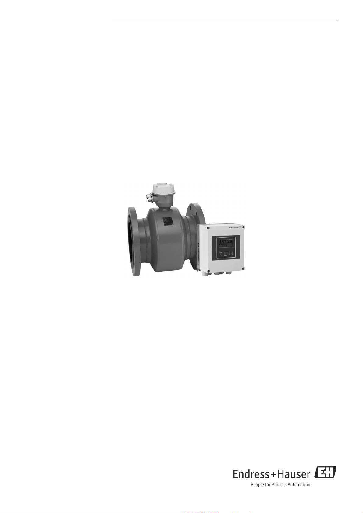
Proline Promag W 800
Electromagnetic flowmeter
Battery powered flowmeter with EN ISO 12944 corrosion protection &
intelligent energy efficient mode
Application
• The electromagnetic measuring principle is unaffected by
pressure, temperature and flow profile
• Certified sensor for the most demanding water and
wastewater applications
Device properties
• International drinking water approvals
• Degree of protection IP68 (Type 6P enclosure)
• Approved for custody transfer to MI-001/OIML R49
• Transmitter housing made of durable polycarbonate
• All in 1 housing incl. batteries & wireless modem
• Measuring intervals can be adapted individually
Your benefits
• For direct underground installation or permanent underwater
use
• Secure, reliable long-term operation – robust and completely
welded sensor
• Energy-saving flow measurement – no pressure loss due to
cross-section constriction
• Maintenance-free – no moving parts
• No power grid required – battery lifetime of up to 15 years
• Worldwide transmission of measured data and events via
email and SMS – integrated GSM/GPRS modem
• Reliable data storage – integrated SD card

Table of contents
Proline Promag W 800
Document information . . . . . . . . . . . . . . . . . . . . . . . . . . .3
Symbols used . . . . . . . . . . . . . . . . . . . . . . . . . . . . . . . . . . . . . . . . . 3
Function and system design . . . . . . . . . . . . . . . . . . . . . .4
Measuring principle . . . . . . . . . . . . . . . . . . . . . . . . . . . . . . . . . . . 4
Measuring system . . . . . . . . . . . . . . . . . . . . . . . . . . . . . . . . . . . . . 4
GSM/GPRS communication . . . . . . . . . . . . . . . . . . . . . . . . . . . . . 6
Custody transfer (optional) . . . . . . . . . . . . . . . . . . . . . . . . . . . . . 7
Input . . . . . . . . . . . . . . . . . . . . . . . . . . . . . . . . . . . . . . . . . .7
Measured variable . . . . . . . . . . . . . . . . . . . . . . . . . . . . . . . . . . . . . 7
Measuring range . . . . . . . . . . . . . . . . . . . . . . . . . . . . . . . . . . . . . . 7
Operable flow range . . . . . . . . . . . . . . . . . . . . . . . . . . . . . . . . . . . 7
Input signal . . . . . . . . . . . . . . . . . . . . . . . . . . . . . . . . . . . . . . . . . . . 7
Output . . . . . . . . . . . . . . . . . . . . . . . . . . . . . . . . . . . . . . . . .8
Output signal . . . . . . . . . . . . . . . . . . . . . . . . . . . . . . . . . . . . . . . . . 8
GSM/GPRS . . . . . . . . . . . . . . . . . . . . . . . . . . . . . . . . . . . . . . . . . . . 8
Signal on alarm . . . . . . . . . . . . . . . . . . . . . . . . . . . . . . . . . . . . . . . 8
Low flow cutoff . . . . . . . . . . . . . . . . . . . . . . . . . . . . . . . . . . . . . . . 8
Galvanic isolation . . . . . . . . . . . . . . . . . . . . . . . . . . . . . . . . . . . . . 8
Data logger (SD card) . . . . . . . . . . . . . . . . . . . . . . . . . . . . . . . . . . 8
Power supply . . . . . . . . . . . . . . . . . . . . . . . . . . . . . . . . . . .8
Battery concept . . . . . . . . . . . . . . . . . . . . . . . . . . . . . . . . . . . . . . . 8
Battery specifications . . . . . . . . . . . . . . . . . . . . . . . . . . . . . . . . . 10
Battery life . . . . . . . . . . . . . . . . . . . . . . . . . . . . . . . . . . . . . . . . . . 11
Terminal assignment . . . . . . . . . . . . . . . . . . . . . . . . . . . . . . . . . 12
Power supply . . . . . . . . . . . . . . . . . . . . . . . . . . . . . . . . . . . . . . . . 12
Power consumption . . . . . . . . . . . . . . . . . . . . . . . . . . . . . . . . . . . 12
Power supply failure . . . . . . . . . . . . . . . . . . . . . . . . . . . . . . . . . . 13
Electrical connection . . . . . . . . . . . . . . . . . . . . . . . . . . . . . . . . . . 13
Potential equalization . . . . . . . . . . . . . . . . . . . . . . . . . . . . . . . . . 15
Terminals . . . . . . . . . . . . . . . . . . . . . . . . . . . . . . . . . . . . . . . . . . . 17
Cable entry . . . . . . . . . . . . . . . . . . . . . . . . . . . . . . . . . . . . . . . . . . 17
Cable specification . . . . . . . . . . . . . . . . . . . . . . . . . . . . . . . . . . . . 17
Remote version cable specifications . . . . . . . . . . . . . . . . . . . . . 18
Performance characteristics . . . . . . . . . . . . . . . . . . . . 19
Reference operating conditions . . . . . . . . . . . . . . . . . . . . . . . . . 19
Maximum measured error . . . . . . . . . . . . . . . . . . . . . . . . . . . . . 19
Repeatability . . . . . . . . . . . . . . . . . . . . . . . . . . . . . . . . . . . . . . . . 19
Degree of protection . . . . . . . . . . . . . . . . . . . . . . . . . . . . . . . . . . 25
Shock and vibration resistance . . . . . . . . . . . . . . . . . . . . . . . . . 26
Mechanical load . . . . . . . . . . . . . . . . . . . . . . . . . . . . . . . . . . . . . . 26
Electromagnetic compatibility (EMC) . . . . . . . . . . . . . . . . . . . . 26
GSM/GPRS signal strength . . . . . . . . . . . . . . . . . . . . . . . . . . . . . 26
Process . . . . . . . . . . . . . . . . . . . . . . . . . . . . . . . . . . . . . . 26
Medium temperature range . . . . . . . . . . . . . . . . . . . . . . . . . . . . 26
Conductivity . . . . . . . . . . . . . . . . . . . . . . . . . . . . . . . . . . . . . . . . . 26
Pressure-temperature ratings . . . . . . . . . . . . . . . . . . . . . . . . . . 26
Pressure tightness . . . . . . . . . . . . . . . . . . . . . . . . . . . . . . . . . . . . 28
Limiting flow . . . . . . . . . . . . . . . . . . . . . . . . . . . . . . . . . . . . . . . . 28
Pressure loss . . . . . . . . . . . . . . . . . . . . . . . . . . . . . . . . . . . . . . . . . 28
System pressure . . . . . . . . . . . . . . . . . . . . . . . . . . . . . . . . . . . . . . 29
Vibrations . . . . . . . . . . . . . . . . . . . . . . . . . . . . . . . . . . . . . . . . . . . 29
Corrosive environment . . . . . . . . . . . . . . . . . . . . . . . . . . . . . . . . 29
Mechanical construction . . . . . . . . . . . . . . . . . . . . . . . 30
Design, dimensions . . . . . . . . . . . . . . . . . . . . . . . . . . . . . . . . . . . 30
Weight . . . . . . . . . . . . . . . . . . . . . . . . . . . . . . . . . . . . . . . . . . . . . 37
Measuring tube specifications . . . . . . . . . . . . . . . . . . . . . . . . . . 38
Material . . . . . . . . . . . . . . . . . . . . . . . . . . . . . . . . . . . . . . . . . . . . 38
Fitted electrodes . . . . . . . . . . . . . . . . . . . . . . . . . . . . . . . . . . . . . 39
Process connections . . . . . . . . . . . . . . . . . . . . . . . . . . . . . . . . . . 39
Surface roughness . . . . . . . . . . . . . . . . . . . . . . . . . . . . . . . . . . . . 39
GSM/GPRS antenna . . . . . . . . . . . . . . . . . . . . . . . . . . . . . . . . . . 39
Operability . . . . . . . . . . . . . . . . . . . . . . . . . . . . . . . . . . . 40
Operating concept . . . . . . . . . . . . . . . . . . . . . . . . . . . . . . . . . . . . 40
Onsite operation . . . . . . . . . . . . . . . . . . . . . . . . . . . . . . . . . . . . . 40
Config 5800 operating tool . . . . . . . . . . . . . . . . . . . . . . . . . . . . 40
Remote operation . . . . . . . . . . . . . . . . . . . . . . . . . . . . . . . . . . . . 40
Languages . . . . . . . . . . . . . . . . . . . . . . . . . . . . . . . . . . . . . . . . . . 40
Certificates and approvals . . . . . . . . . . . . . . . . . . . . . . 41
CE mark . . . . . . . . . . . . . . . . . . . . . . . . . . . . . . . . . . . . . . . . . . . . 41
Drinking water approval . . . . . . . . . . . . . . . . . . . . . . . . . . . . . . . 41
Other standards and guidelines . . . . . . . . . . . . . . . . . . . . . . . . . 41
GSM approvals . . . . . . . . . . . . . . . . . . . . . . . . . . . . . . . . . . . . . . . 41
Declaration of Conformity . . . . . . . . . . . . . . . . . . . . . . . . . . . . . 41
Measuring device approval . . . . . . . . . . . . . . . . . . . . . . . . . . . . . 42
Ordering information . . . . . . . . . . . . . . . . . . . . . . . . . . 43
Installation . . . . . . . . . . . . . . . . . . . . . . . . . . . . . . . . . . . 20
Mounting location . . . . . . . . . . . . . . . . . . . . . . . . . . . . . . . . . . . . 20
Orientation . . . . . . . . . . . . . . . . . . . . . . . . . . . . . . . . . . . . . . . . . . 22
Inlet and outlet runs . . . . . . . . . . . . . . . . . . . . . . . . . . . . . . . . . . 23
Adapters . . . . . . . . . . . . . . . . . . . . . . . . . . . . . . . . . . . . . . . . . . . . 23
Length of connecting cable . . . . . . . . . . . . . . . . . . . . . . . . . . . . 24
Special installation . . . . . . . . . . . . . . . . . . . . . . . . . . . . . . . . . . . 24
Environment . . . . . . . . . . . . . . . . . . . . . . . . . . . . . . . . . 25
Ambient temperature range . . . . . . . . . . . . . . . . . . . . . . . . . . . 25
Storage temperature . . . . . . . . . . . . . . . . . . . . . . . . . . . . . . . . . . 25
Altitude . . . . . . . . . . . . . . . . . . . . . . . . . . . . . . . . . . . . . . . . . . . . . 25
Atmosphere . . . . . . . . . . . . . . . . . . . . . . . . . . . . . . . . . . . . . . . . . 25
Accessories . . . . . . . . . . . . . . . . . . . . . . . . . . . . . . . . . . . 44
Device-specific accessories . . . . . . . . . . . . . . . . . . . . . . . . . . . . . 44
Communication-specific accessories . . . . . . . . . . . . . . . . . . . . . 44
Sevice-specific accessories . . . . . . . . . . . . . . . . . . . . . . . . . . . . . 44
Documentation . . . . . . . . . . . . . . . . . . . . . . . . . . . . . . . 45
Standard documentation . . . . . . . . . . . . . . . . . . . . . . . . . . . . . . 45
Supplementary device-dependent documentation . . . . . . . . . 45
Registered trademarks . . . . . . . . . . . . . . . . . . . . . . . . . 45
2 Endress+Hauser
Proline Promag W 800
Document information
Symbols used Electrical symbols
Symbol Meaning
A0011197
A0011198
A0011200
A0011199
A0011201
Direct current
A terminal at which DC voltage is present or through which direct current flows.
Alternating current
A terminal at which alternating voltage (sinusoidal) is present or through which
alternating current flows.
Ground connection
A grounded terminal which, from the viewpoint of the user, is grounded via a grounding
system.
Protective ground connection
A terminal which must be connected to ground prior to establishing any other
connections.
Equipotential connection
A connection that must be connected to the plant grounding system:
This may be a potential equalization line or a star grounding system depending on
national or company codes of practice.
Symbols for types of information
Symbol Meaning
Permitted
Indicates procedures, processes or actions that are permitted.
A0011182
Preferred
Indicates procedures, processes or actions that are preferred.
A0011183
Forbidden
Indicates procedures, processes or actions that are forbidden.
A0011200
Tip
Indicates additional information.
A0011193
Reference to documentation
Refers to the corresponding device documentation.
A0011194
Reference to page
Refers to the corresponding page number.
A0011195
Reference to graphic
Refers to the corresponding graphic number and page number.
A0011196
Symbols in graphics
Symbol Meaning
1, 2, 3 … Item numbers
A, B, C etc. Views
A-A, B-B, C-C
Sections
etc.
Flow direction
A0013441
Endress+Hauser 3
Proline Promag W 800
I
L
B
I
U
e
v
Function and system design
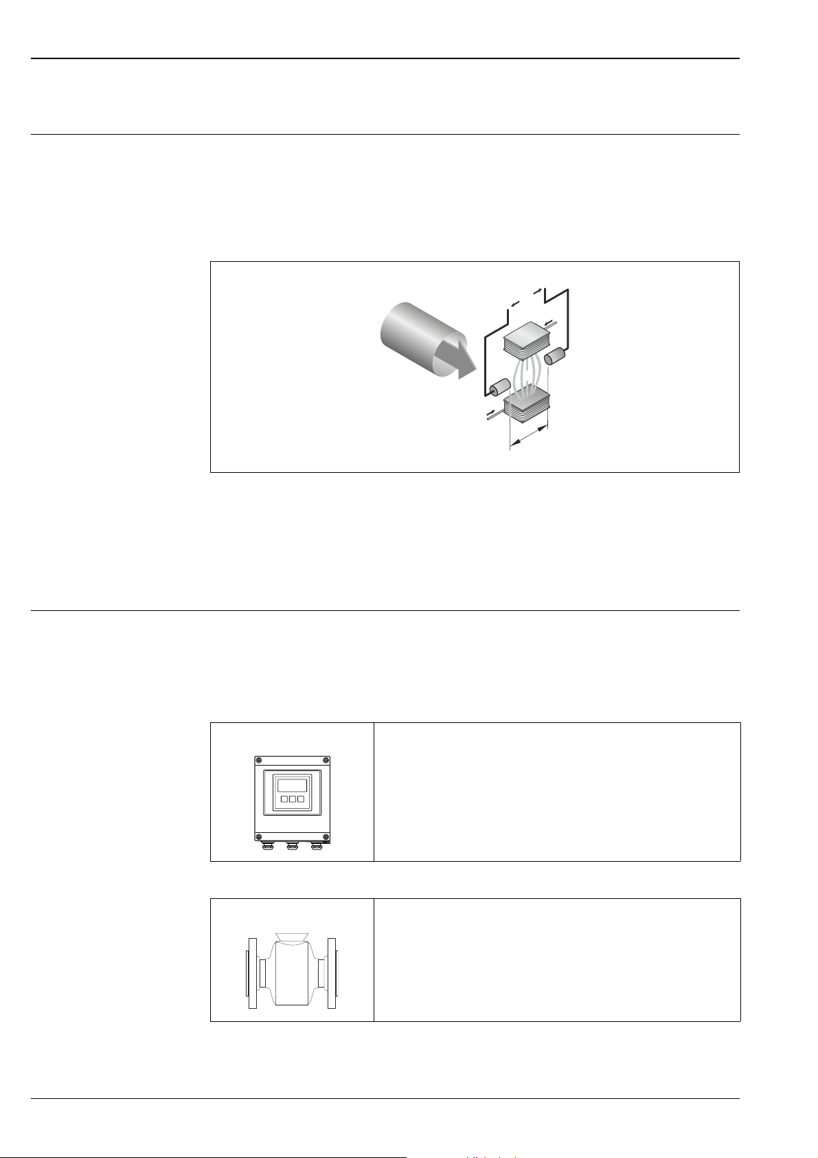
Measuring principle Following Faraday's law of magnetic induction, a voltage is induced in a conductor moving through a
magnetic field.
In the electromagnetic measuring principle, the flowing medium is the moving conductor.
The voltage induced is proportional to the flow velocity and is supplied to the amplifier via two
measuring electrodes. The flow volume is calculated via the pipe cross-sectional area. The DC magnetic
field is created through a switched direct current of alternating polarity.
Ue = B · L · v ; Q = A · v
Ue Induced voltage
B Magnetic induction (magnetic field)
L Electrode spacing
v Flow velocity
Q Volume flow
A Pipe cross-section
I Current strength
Measuring system The device consists of a transmitter and a sensor.
Two device versions are available:
• Compact version – the transmitter and sensor form a mechanical unit.
• Remote version – the transmitter and sensor are mounted separately from one another.
Transmitter
Promag 800
A0017117
Device versions and materials:
• Compact housing: polycarbonate plastic
• Wall-mount housing: polycarbonate plastic
Configuration
• Local operation, key-based operation, eight-line
• Config5800 software operating tool
Separate GSM/GPRS antenna optionally available.
A0017035
Sensor
Promag W
4 Endress+Hauser
A0022673
Nominal diameters: DN 25 to 300 (1 to 12")
Materials:
• Sensor: fully welded with protective varnish
• Measuring tube: stainless steel 1.4301/304, 1.4306/304L
• Liner: polyurethane, hard rubber
• Electrodes: 1.4435, Alloy C-22
• Connection housing, remote version: polycarbonate plastic (IP68)
Proline Promag W 800
1
2
3
4
5
6
7
8
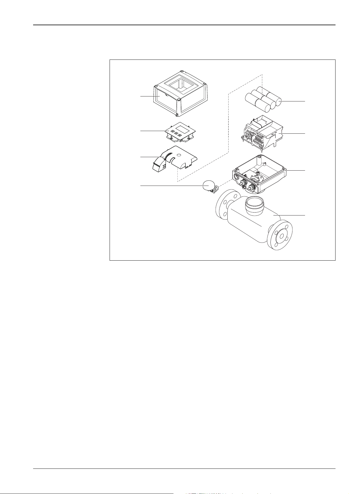
Device design
A0016254
Primary components of the measuring device
1 Cover for transmitter housing
2 Display and operating module
3 Cover for battery compartment
4 GSM antenna (optional: only supplied with delivery if the "GSM/GPRS" option is ordered)
5 Batteries (number depends on the order, battery concept
6 Bracket for electronics board incl. battery compartment
7Transmitter housing
8Sensor
ä
8)
Endress+Hauser 5
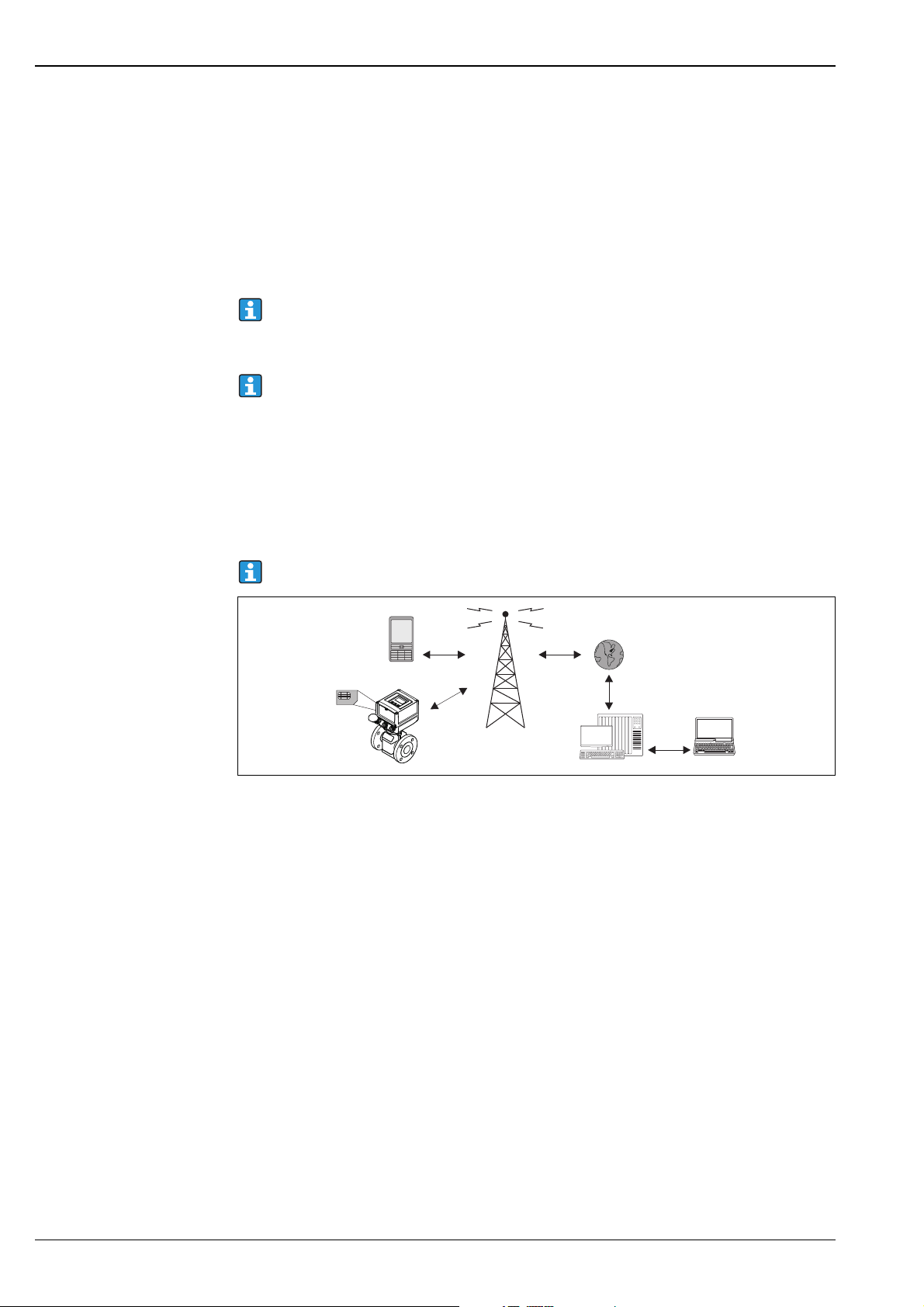
GSM/GPRS communication Wireless GSM/GPRS transmission of information
1–
4GHI
7PORS
*
2ABC
5JKL
8TUV
0+
3DEF
6MNO
9WXYZ
//
WWW
1
2
5
6
3
4
3
Data can be transmitted to and from the measuring device via wireless communication. Ideal for
applications in which the measuring point is installed in a remote location, making tasks like reading
counters very time-consuming activities.
As it is possible to configure limit value monitoring with alarms signaled by e-mail or SMS, operators
can respond specifically to local changes:
• SMS: receive alarms, query totalizer counter readings, change the device configuration etc.
• E-mail: The data saved by the data logger are sent by e-mail in a defined period of time (e.g. once a
day). A CSV-file is attached to the e-mail.
To send e-mails, the measuring device must be able to access an SMTP server. The measuring
device does not support encrypted login (e.g. SSL/TSL using TCP Port 465), as the processing
power and, consequently, power consumption would be too high.
For configuration information, see "Operating Instructions" document
It is important to ensure that the signal of the mobile communications network is strong enough
to enable the system to dial into the GPRS/GSM network.
Mobile communications network (GSM: Global System for Mobile Communications )
Data can be transmitted via a mobile communications network with the GSM/GPRS modem. The
modem can be configured as a point-to-point connection or as a modem that can be openly accessed
via the Internet/intranet.
A SIM card from a mobile communications provider is required for the GSM/GPRS mode.
The communication is established via the data channel of the SIM card.
Additional activation might be required for this card depending on the GSM/GPRS provider.
The SIM card must be activated for GPRS operation.
Proline Promag W 800
A0017029
Operation of the measuring device in the mobile communications network
1 Measuring device with SIM card
2 Cellular phone
3GSM network
4 GPRS network
5 Web server (provider)
6 Laptop (customer)
GPRS support
GPRS (General Packet Radio Services) is a mobile communications technology that takes advantage of
the benefits afforded by packageoriented data transmission and channel bundling.
In contrast to normal connections, an entire channel is not reserved for the duration of the connection
between the mobile device and the base station when transmitting data via GPRS. Instead, the data are
grouped into data packets which can be transmitted depending on the requirements and capacity.
Higher transmission rates are possible with packet-based data transmission. This allows the
measuring system to connect periodically to the Internet, an intranet or a mailbox. Data are then only
transmitted if required, such as if a new e-mail is sent or received.
Therefore communication via GPRS-based operation of the measuring system provides the simplest
and most cost-effective way of connecting a measuring point periodically to the Internet or an intranet.
!
Note!
If the device is in service subject to legal metrological control, the wireless transmission of billingspecific data via GSM/GPRS is for information purposes only and is not legally binding.
6 Endress+Hauser

Proline Promag W 800
Custody transfer (optional)
!
!
Note!
As an option, Promag W 800 is tested in accordance with OIML R49 and has an EC type-examination
certificate as per Measuring Instruments Directive 2004/22/EC (MID) for service subject to legal
metrological control ("custody transfer") for cold water (Annex MI-001).
The permitted fluid temperature in these applications is 0 to +50 °C (+32 to +122 °F).
It is used with a legally controlled totalizer on the local display.
Measuring devices subject to legal metrological control totalize in both directions, i.e. all the outputs
consider flow components in the positive (forward) and negative (reverse) flow direction.
Generally a measuring device subject to legal metrological control is secured against tampering by lead
seals on the transmitter or sensor.
These lead seals may normally only be opened by a representative of the competent authority for legal
metrology controls.
Note!
After putting the device into circulation or after sealing the device, operation via the onsite display, via
the Config 5800 software operating tool or via GSM/GPRS is only possible to a limited extent.
Detailed ordering information is available from your local Endress+Hauser sales center for
national approvals as cold water meters based on OIML R49.
Input
Measured variable Direct measured variables
Volume flow (proportional to induced voltage)
Calculated measured variables
Mass flow
!
Measuring range Typically v = 0.01 to 10 m/s (0.03 to 33 ft/s) with the specified accuracy
Operable flow range Over 1000 : 1
Note!
In custody transfer: only volume flow.
To calculate the measuring range, use the Applicator sizing tool ( ä 44)
Recommended measuring range
"Limiting flow" section
Im eichpflichtigen Verkehr:
160 : 1
Näheres regelt die jeweils gültige Zulassung.
Input signal Status input (auxiliary input)
• U = 3 to 40 V DC
•R = 5 k
• Galvanically isolated
• Can be configured for:
totalizer reset, positive zero return, error message reset.
Endress+Hauser 7

Output
Output signal Status/pulse output
• Passive
• Opto-MOS (opto-isolated output)
• Max. switching voltage: 40 V DC / 28 V AC
• Max. switching current: 100 mA
•Max. R
• Max. switching frequency (RL = 240 , V
• Isolated from other secondary circuits: 500 V DC
GSM/GPRS GSM/GPRS modem
• For data transmission via a GSM network (TDMA/FMDA)
• Integrated on the electronics board
• Quad-band: 850, 900, 1800, 1900 MHz
• Mail and messaging (SMS) functions
– Measuring device configuration
– Measuring device diagnostics
– Flow protocol data (automatic transmission)
– Totalizer: positive/negative/net values (balance) (automatic transmission)
– Alarms (at the time of the event)
: 70
on
= 24 V DC): 50 Hz
OUT
Proline Promag W 800
Signal on alarm Status/pulse output
“Not conductive” in the event of fault or power supply failure
Low flow cutoff Switch points can be selected for low flow cutoff between 0 and 25 % of the full scale value.
Galvanic isolation All circuits for inputs, outputs and power supply are galvanically isolated from each other.
Data logger (SD card) • The integrated data logger can log the following data:
– Reference data: time, date, consecutive numbers in list etc.
– Totalizer counter readings: positive, negative, net (balance)
– Flow: in volume unit (e.g. m3/h) or in %
– Measuring cycles per hour, state of charge of the individual battery packs (B1, B2, B3),
temperature of the electronics board
• Configurable save cycle: 15 seconds to 24 hours.
• The data of the data logger are not lost if the battery is replaced.
The data logger gives users the option of second, parallel data recording in a higher resolution within
a specific period of time.
The data are saved daily in a new file on the micro SD card (storage capacity 2 GB). Via the FXA291
service interface, the files can be saved for evaluation on a PC or laptop with the Config5800 operating
software. It is also possible to transmit the files by e-mail via the GSM/GPRS modem, which is available
as an option.
Power supply
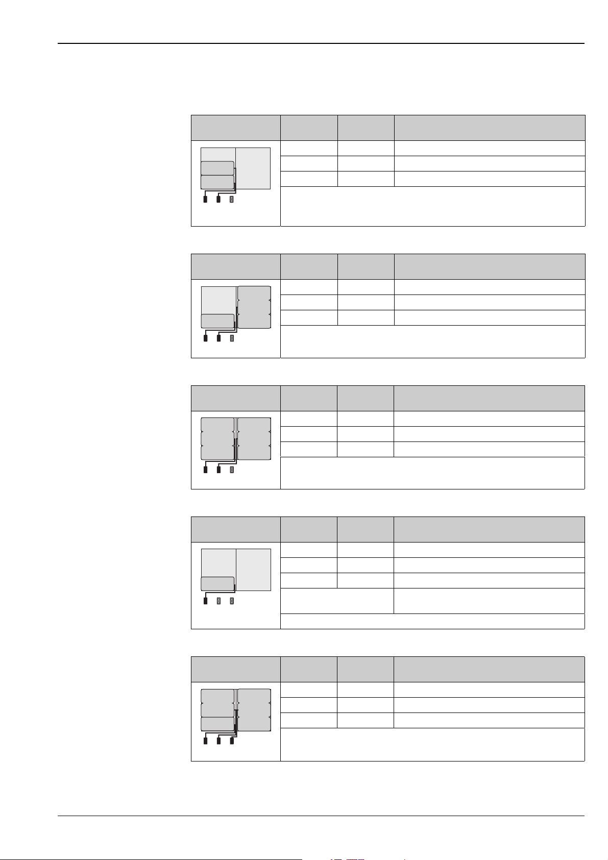
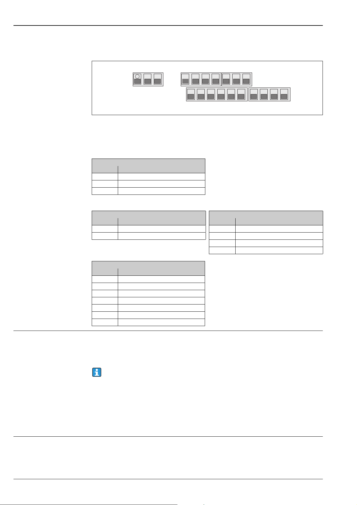
Battery concept Battery arrangement options
Three battery terminals are available in the measuring device. These terminals are assigned different
uses depending on the number and arrangement of the batteries. B1 and B2 are the terminals for
power supply to the measuring device, B3 is the terminal for the GSM/GPRS modem.
The measuring device is initially powered by the batteries in terminal B2. If the voltage supplied by
these batteries becomes too low, the measuring device issues a message and switches automatically to
the battery in terminal B1.
If power is supplied to the measuring device externally and the power supply fails, the battery in
terminal B1 acts as a backup power supply.
The GSM/GPRS modem is always powered by the battery in terminal B3.
8 Endress+Hauser
Proline Promag W 800
B2
B1
B1 B2 B3
B1
B1 B2 B3
B2
B1 B2 B3
B2B1
B1
B1 B2 B3
B1
B1 B2 B3
B3
B2
This is also the case if the measuring device uses an external power supply.
Configuration 1
Configuration of
batteries
Configuration 2
Configuration of
batteries
Configuration 3
Configuration of
batteries
Connectors
Number of
batteries
Battery usage
B 1 1 Backup power supply for the measuring device
B 2 1 Power supply for the measuring device
B 3 – Power supply for the GSM/GPRS modem
"Power supply" order feature for this configuration: 5W8B**–***F0********
Note!
!
A0017127
Not permitted in custody transfer!
Connectors
Number of
batteries
Battery usage
B 1 1 Backup power supply for the measuring device
B 2 3 Power supply for the measuring device
B 3 – Power supply for the GSM/GPRS modem
"Power supply" order feature for this configuration: 5W8B**–***G0********
A0017128
Connectors
Number of
batteries
Battery usage
B 1 3 Backup power supply for the measuring device
B 2 3 Power supply for the measuring device
B 3 – Power supply for the GSM/GPRS modem
"Power supply" order feature for this configuration: 5W8B**–***H0********
Configuration 4
Configuration of
batteries
Configuration 5
Configuration of
batteries
A0017129
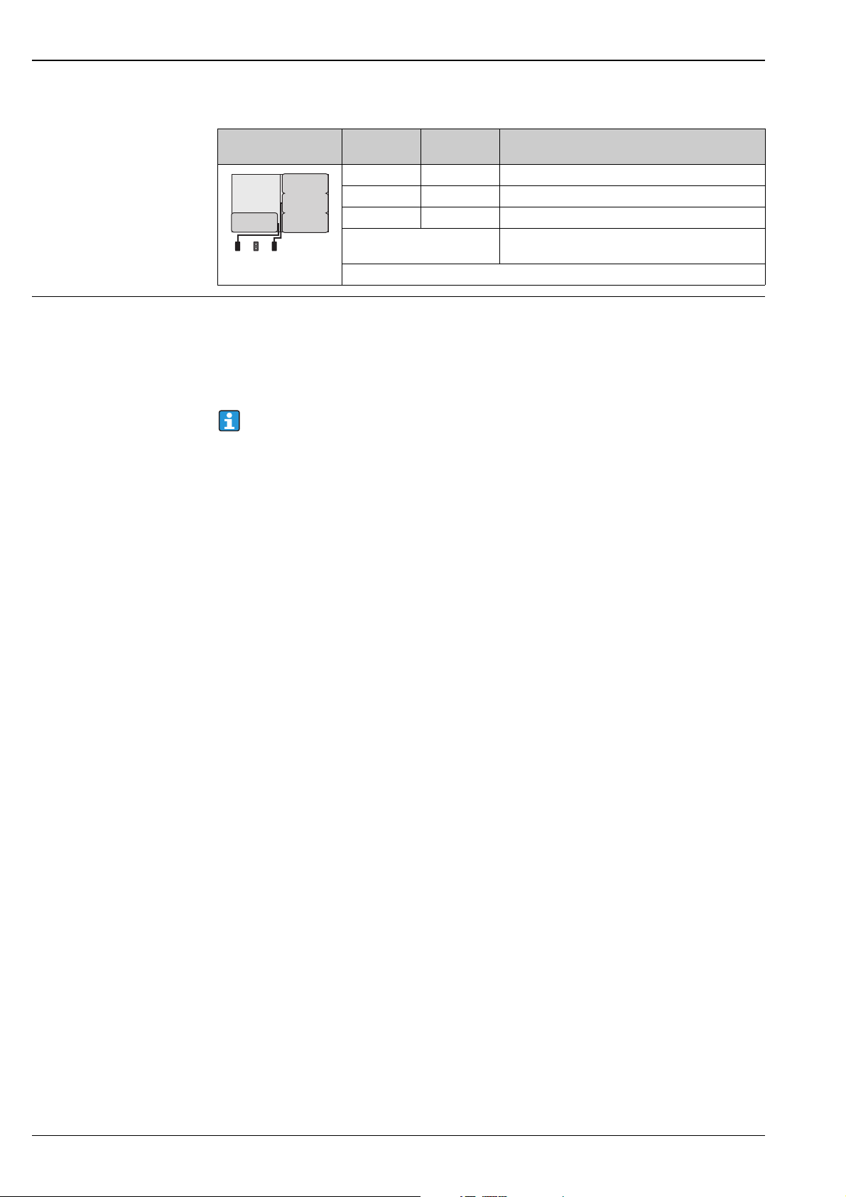
Connectors
Number of
batteries
Battery usage
B 1 1 Backup power supply for the measuring device
B 2 – Power supply for the measuring device
B 3 – Power supply for the GSM/GPRS modem
Powered via external power
Power supply for the measuring device
supply
A0017130
"Power supply" order feature for this configuration: 5W8B**–***J0********
Connectors
Number of
batteries
Battery usage
B 1 1 Backup power supply for the measuring device
B 2 2 Power supply for the measuring device
B 3 3 Power supply for the GSM/GPRS modem
"Power supply" order feature for this configuration: 5W8B**–***HP********
A0017131
Endress+Hauser 9
Configuration 6
B1
B1 B2 B3
B3
Proline Promag W 800
Configuration of
batteries
Connectors
B 1 1 Backup power supply for the measuring device
B 2 – Power supply for the measuring device
B 3 3 Power supply for the GSM/GPRS modem
Powered via external power
A0017132
"Power supply" order feature for this configuration: 5W8B**–***KP********
supply
Number of
batteries
Battery usage
Power supply for the measuring device
Battery specifications • Lithium-thionyl chloride high-power batteries (size D)
•3.6 V DC
• Not rechargeable
• 19 Ah nominal capacity at 20 °C (per battery)
• Battery lasts for up to 15 years (Battery life)
• Required battery quantity and possible battery arrangement ä 8
Lithium-thionyl chloride high-power batteries are categorized as Class 9:
"Miscellaneous Hazardous Materials".
Comply strictly with the hazardous material regulations described in the safety data sheet.
You can request the safety data sheet from your Endress+Hauser Sales Center.
10 Endress+Hauser
Proline Promag W 800
1
a
b
c
d
5/10 Hz
3 Sec.
15 Sec.
5 Sec.
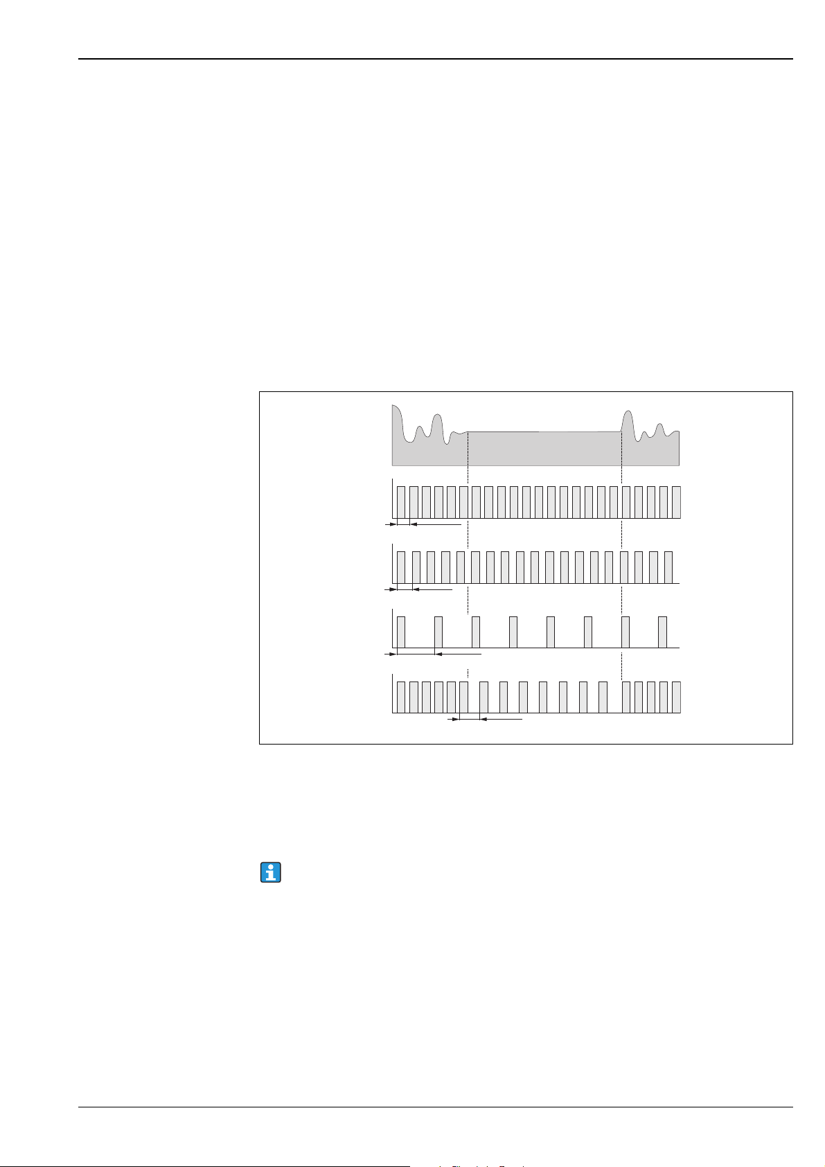
Battery life The battery has a maximum battery life of 15 years.
The battery life, and thereby the availability of the measuring device if powered by batteries, depends
on a number of factors, including:
• The number of batteries
• The ambient conditions
• The frequency of data transmission via the GSM/GPRS modem
• The size of the files transmitted
• The interface activities (use of local operation, GSM/GPRS modem etc.)
• The selected measured value acquisition method:
– "MAX. LIVE" (max. battery life): measured value acquired every 15 seconds.
– "SMART" (dynamic control of measurement data acquisition): measured value acquisition depends
on the flow profile. The measuring device records the measured value every 5 seconds. The
frequency of the measured value acquisition cycle is increased if the measuring device detects a
change in the flow profile. The measuring device is supplied with the "SMART" measuring mode as
standard.
– "AVERAGE": measured value acquisition every 3 seconds.
– "CONTINUOUS": continuous measured value acquisition.
A0017032
Operating principle of the different measured value acquisition methods
1 Flow profile
a CONT.PWR
bAVERAGE
cMAX. LIFE
dSMART
Contact your Endress+Hauser Sales Center to calculate the battery life for your specific operating
conditions.
Endress+Hauser 11
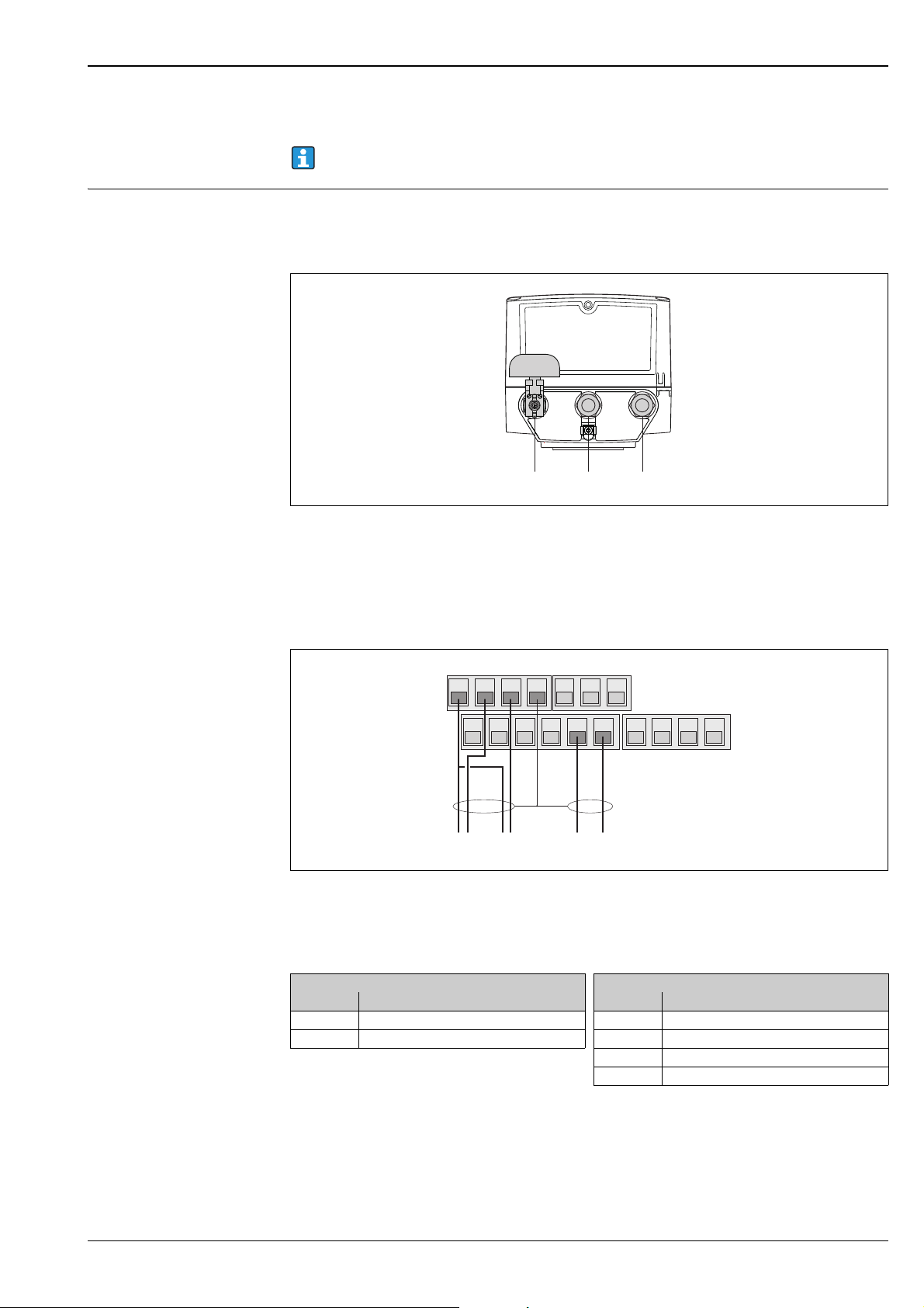
Terminal assignment Transmitter
17
16 15 14
10
98765
13
12 11
4321
)
12
3
A
B
Transmitter terminal assignment
A Terminals: connection of external power supply (optional)
B Terminals: signal transmission via inputs and outputs, connection of remote version
Terminals (A): connection of external power supply (optional)
Terminal Connection
1Protective ground
2N –
3L +
Proline Promag W 800
A0017259
External power supply
Terminals (B): signal transmission via inputs and outputs, connection of remote version
Terminal Connection Terminal Connection
5 Input 1 (+) 14 Shield, output 1 and 2
6 Input 1 (–) 15 Output 1 (+)
Remote version connection
Terminal Connection
1 Electrode E1 (brown)
2 Electrode E2 (white)
3 Shield, electrode E1 (brown)
4 Shield, electrode E2 (white)
11 Reference electrode (green)
12 Coil current cable B2 (black)
13 Coil current cable B1 (black)
Power supply Power from batteries
•3.6 V DC
• 19 Ah nominal capacity at 20 °C (per battery)
• Max. power: 200 mW
Battery life ä 11
Inputs Outputs
16 Output 2 (+)
17 Output 1 and 2 (–)
Supply voltage via external power supply (optional)
• 100 to 240 V AC / 12 to 60 V DC
• 44 to 66 Hz
•Max. power: 3 W
• A battery to act as a back up if the power supply fails
Caution!
"
The values specified for the supply voltage may not be exceeded.
Power consumption Switch-on current:
• Max. 30 A at 240 V AC
• Max. 6 A at 24 V DC
12 Endress+Hauser
Proline Promag W 800
123
17
16 15 14
10
98765
13
12 11
4321
–2+– +1–+
3
Power supply failure Lasting min. ½ cycle frequency:
The battery in terminal B1 acts as a power backup if power is supplied to the measuring device
externally and the power supply fails.
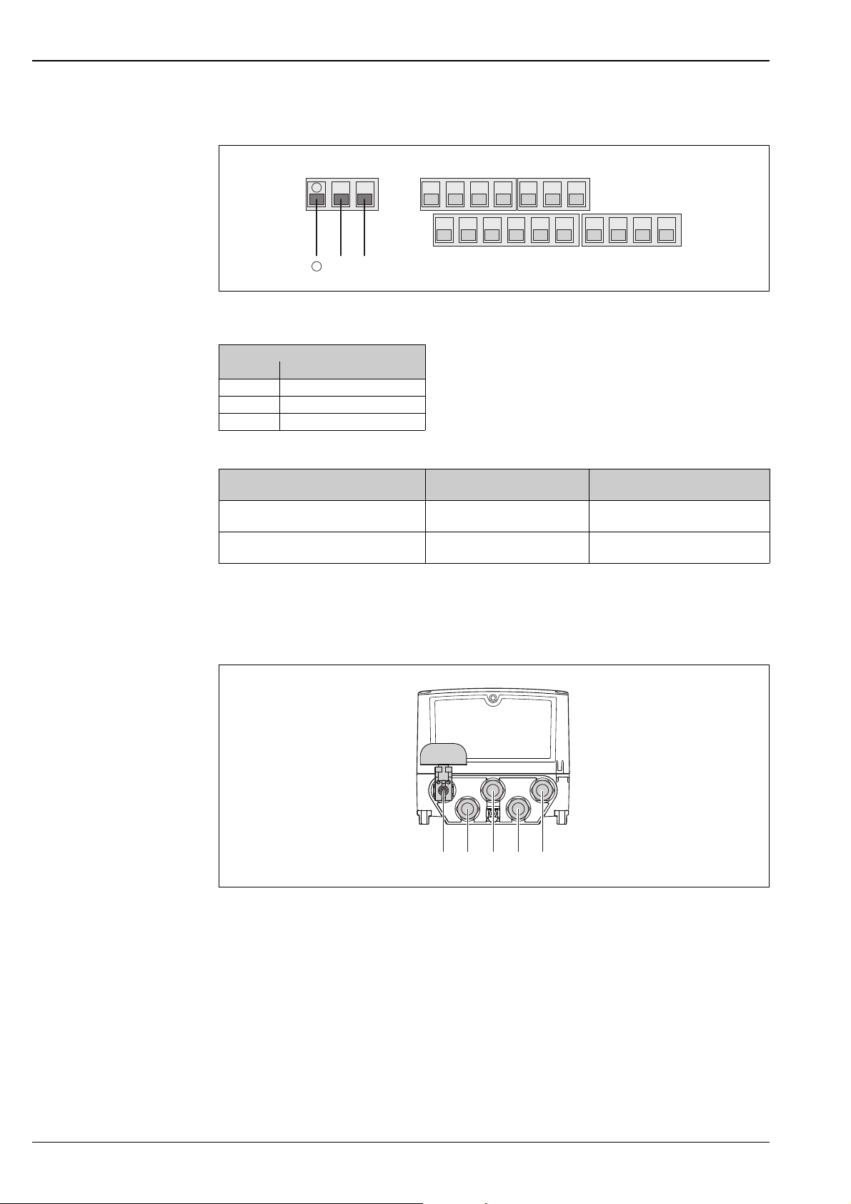
Electrical connection Connecting the transmitter
Cable entries for the compact version
Cable entries for the compact version
1 Connection terminal for GSM antenna (optional)
2 External power supply (optional)
3 Inputs/outputs
Connecting the inputs and outputs
Connecting the outputs
1 Output 1
2 Output 2
3Input 1
A0016457
A0017026
Endress+Hauser 13
Inputs Outputs
Terminal Connection Terminal Connection
5 Input 1 (+) 14 Shield, output 1 and 2
6 Input 1 (–) 15 Output 1 (+)
16 Output 2 (+)
17 Output 1 and 2 (–)
Connecting the external power supply (optional)
17
16 15 14
10
98765
13
12 11
4321
N– L+
)
)
12
3
1234
5
Connecting the external power supply (optional)
External power supply
Terminal Connection
1Protective ground
2N –
3L +
Orderable combinations:
Ordered feature
"Power supply"
5W8B**-***J*********
5W8B**-***K*********
100 to 240 V AC
100 to 240 V AC
Power
supply
12 to 60 V DC
12 to 60 V DC
Proline Promag W 800
A0017028
Number of
batteries
1 back-up battery
1 back-up battery
3 batteries for GSM/GPRS module
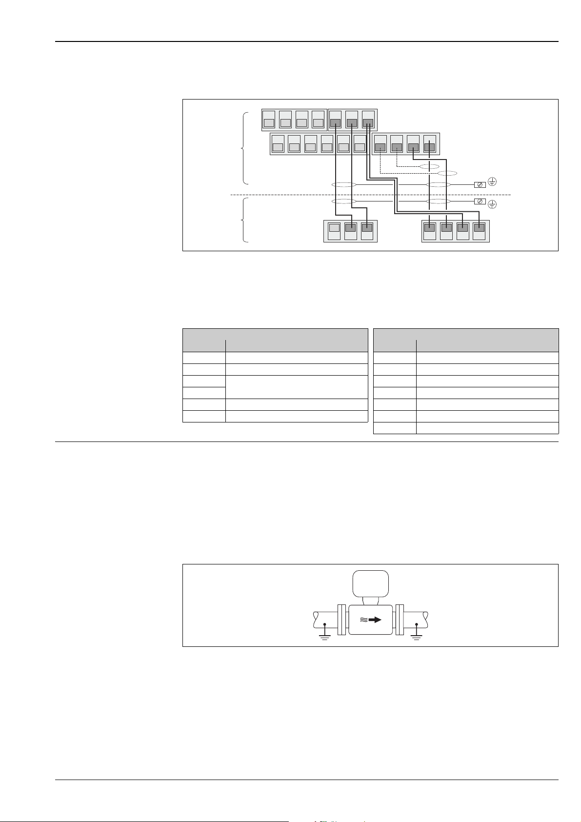
Connecting the remote version
Cable entries for the remote version
Cable entries for the remote version
1 Connection terminal for GSM antenna (optional)
2 External power supply (optional)
3 Inputs/outputs
4 Coil current cable
5 Electrode cable
A0016458
14 Endress+Hauser
Proline Promag W 800
1
2
3
4
17
16 15 14
10
987 65
13
12 11
4 321
5 743742 41
Connecting the remote version
Connecting the remote version
1 Transmitter terminals
2 Sensor terminals
3 Coil current cable
4 Electrode cable
A0017027
Terminal Connection Terminal Connection
5 Electrode E1 (brown) 1 Electrode E1 (brown)
7 Electrode E2 (white) 2 Electrode E2 (white)
4
Reference electrode,
Terminals bridged (green)
37 4 Shield, electrode E2 (white)
41 Coil current cable B2 (black) 11 Reference electrode (green)
42 Coil current cable B1 (black) 12 Coil current cable B2 (black)
Potential equalization Requirements
Please consider the following to ensure correct measurement:
• The fluid and sensor have the same electrical potential
• Company-internal grounding concepts
• Material and grounding of the pipes
Connection example in standard situations
Metal, grounded pipe
Sensor Transmitter
3 Shield, electrode E1 (brown)
13 Coil current cable B1 (black)
A0016315
Potential equalization via Measuring tube
Endress+Hauser 15
 Loading...