

Page 1
TI01227D/06/EN/04.18
71402619
2018-06-01
Products Solutions Services
Technical Information
Proline Promag W 500
Electromagnetic flowmeter
The remote version with up to 3 I/Os and a sensor with EN ISO 12944
corrosion protection
Application
• The bidirectional measuring principle is virtually
independent of pressure, density, temperature and viscosity
• The specialist in the water and wastewater industry for the
most demanding applications
Device properties
• International drinking water approvals
• Degree of protection IP68 (Type 6P enclosure)
• Remote version with up to 3 I/Os
• Backlit display with touch control and WLAN access
• Standard cable between sensor and transmitter
Your benefits
• For direct underground installation or permanent
underwater use
• Secure, reliable long-term operation – robust and completely
welded sensor
• Energy-saving flow measurement – no pressure loss due to
cross-section constriction
• Maintenance-free – no moving parts
• Full access to process and diagnostic information –
numerous, freely combinable I/Os and fieldbuses
• Reduced complexity and variety – freely configurable I/O
functionality
• Integrated verification – Heartbeat Technology
Page 2

Table of contents
Proline Promag W 500
About this document ........................ 4
Symbols used ................................ 4
Function and system design ................... 5
Measuring principle ............................ 5
Measuring system ............................. 6
Equipment architecture ......................... 8
Safety ..................................... 8
Input .................................... 10
Measured variable ............................ 10
Measuring range ............................. 10
Operable flow range ........................... 12
Input signal ................................ 12
Output .................................. 14
Output and input variants ....................... 14
Output signal ............................... 15
Signal on alarm .............................. 18
Ex connection data ........................... 21
Low flow cut off ............................. 22
Galvanic isolation ............................ 22
Protocol-specific data .......................... 22
Power supply ............................. 27
Terminal assignment .......................... 27
Device plugs available .......................... 28
Pin assignment, device plug ...................... 29
Supply voltage .............................. 30
Power consumption ........................... 31
Current consumption .......................... 31
Power supply failure .......................... 31
Electrical connection .......................... 32
Potential equalization ......................... 41
terminals .................................. 43
Cable entries ............................... 43
Cable specification ............................ 43
Performance characteristics .................. 45
Reference operating conditions ................... 45
Maximum measured error ....................... 45
Repeatability ............................... 46
Influence of ambient temperature ................. 46
Installation ............................... 46
Mounting location ............................ 46
Orientation ................................ 48
Inlet and outlet runs .......................... 48
Adapters .................................. 49
Length of connecting cable ...................... 49
Mounting the transmitter housing ................. 51
Special mounting instructions .................... 51
Environment .............................. 52
Ambient temperature range ..................... 52
Storage temperature .......................... 53
Degree of protection .......................... 53
Vibration resistance ........................... 53
Shock resistance ............................. 53
Shock resistance ............................. 53
Mechanical load ............................. 53
Electromagnetic compatibility (EMC) ............... 53
Process .................................. 53
Medium temperature range ...................... 53
Conductivity ................................ 54
Pressure-temperature ratings .................... 54
Pressure tightness ............................ 56
Flow limit ................................. 56
Pressure loss ............................... 57
System pressure ............................. 57
Vibrations ................................. 58
Mechanical construction .................... 58
Dimensions in SI units ......................... 58
Dimensions in US units ......................... 74
Weight ................................... 86
Measuring tube specification ..................... 90
Materials .................................. 91
Fitted electrodes ............................. 94
Process connections ........................... 94
Surface roughness ............................ 94
Operability ............................... 94
Operating concept ............................ 94
Languages ................................. 95
Local operation .............................. 95
Remote operation ............................ 95
Service interface ............................ 101
Network integration .......................... 102
Supported operating tools ...................... 103
HistoROM data management .................... 104
Certificates and approvals .................. 106
CE mark .................................. 106
C-Tick symbol .............................. 106
Ex approval ............................... 106
Pharmaceutical compatibility .................... 107
Drinking water approval ....................... 107
HART certification ........................... 107
FOUNDATION Fieldbus certification ............... 107
Certification PROFIBUS ........................ 108
EtherNet/IP certification ....................... 108
Certification PROFINET ........................ 108
Radio approval ............................. 108
Other standards and guidelines .................. 108
Ordering information ...................... 109
Application packages ...................... 109
Diagnostics functions ......................... 109
Heartbeat Technology ........................ 109
Cleaning ................................. 110
OPC-UA server ............................. 110
2 Endress+Hauser
Page 3

Proline Promag W 500
Accessories .............................. 110
Device-specific accessories ...................... 110
Communication-specific accessories ............... 111
Service-specific accessories ..................... 112
System components .......................... 112
Supplementary documentation .............. 113
Standard documentation ....................... 113
Device-dependent additional documentation ......... 113
Registered trademarks ..................... 114
Endress+Hauser 3
Page 4
About this document
A
Symbols used Electrical symbols
Symbol Meaning
Proline Promag W 500
Direct current
Alternating current
Direct current and alternating current
Ground connection
A grounded terminal which, as far as the operator is concerned, is grounded via a
grounding system.
Protective Earth (PE)
A terminal which must be connected to ground prior to establishing any other
connections.
The ground terminals are situated inside and outside the device:
• Inner ground terminal: Connects the protectiv earth to the mains supply.
• Outer ground terminal: Connects the device to the plant grounding system.
Communication symbols
Symbol Meaning
Wireless Local Area Network (WLAN)
Communication via a wireless, local network.
LED
Light emitting diode is off.
LED
Light emitting diode is on.
LED
Light emitting diode is flashing.
Symbols for certain types of information
Symbol Meaning
Permitted
Procedures, processes or actions that are permitted.
Preferred
Procedures, processes or actions that are preferred.
Forbidden
Procedures, processes or actions that are forbidden.
Tip
Indicates additional information.
Reference to documentation.
Reference to page.
Reference to graphic.
Visual inspection.
4 Endress+Hauser
Page 5
Proline Promag W 500
1.
-
.
U
e
L
B
I
I
v
Symbols in graphics
Symbol Meaning
1, 2, 3, ... Item numbers
, 2., 3., … Series of steps
A, B, C, ... Views
A-A, B-B, C-C, ... Sections
Hazardous area
Safe area (non-hazardous area)
Flow direction
Function and system design
Measuring principle
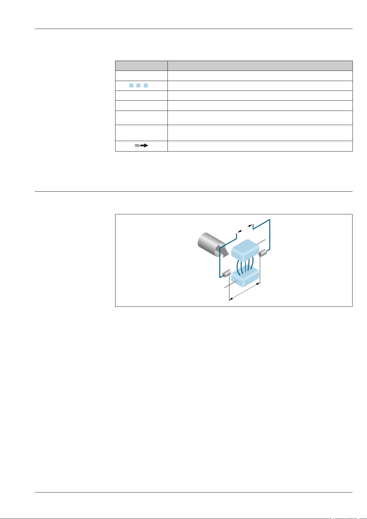
Following Faraday's law of magnetic induction, a voltage is induced in a conductor moving through a
magnetic field.
A0028962
Ue Induced voltage
B Magnetic induction (magnetic field)
L Electrode spacing
I Current
v Flow velocity
In the electromagnetic measuring principle, the flowing medium is the moving conductor. The
voltage induced (Ue) is proportional to the flow velocity (v) and is supplied to the amplifier by means
of two measuring electrodes. The flow volume (Q) is calculated via the pipe cross-section (A). The DC
magnetic field is created through a switched direct current of alternating polarity.
Formulae for calculation
• Induced voltage Ue = B · L · v
• Volume flow Q = A · v
Endress+Hauser 5
Page 6
Proline Promag W 500
1
3
4
2
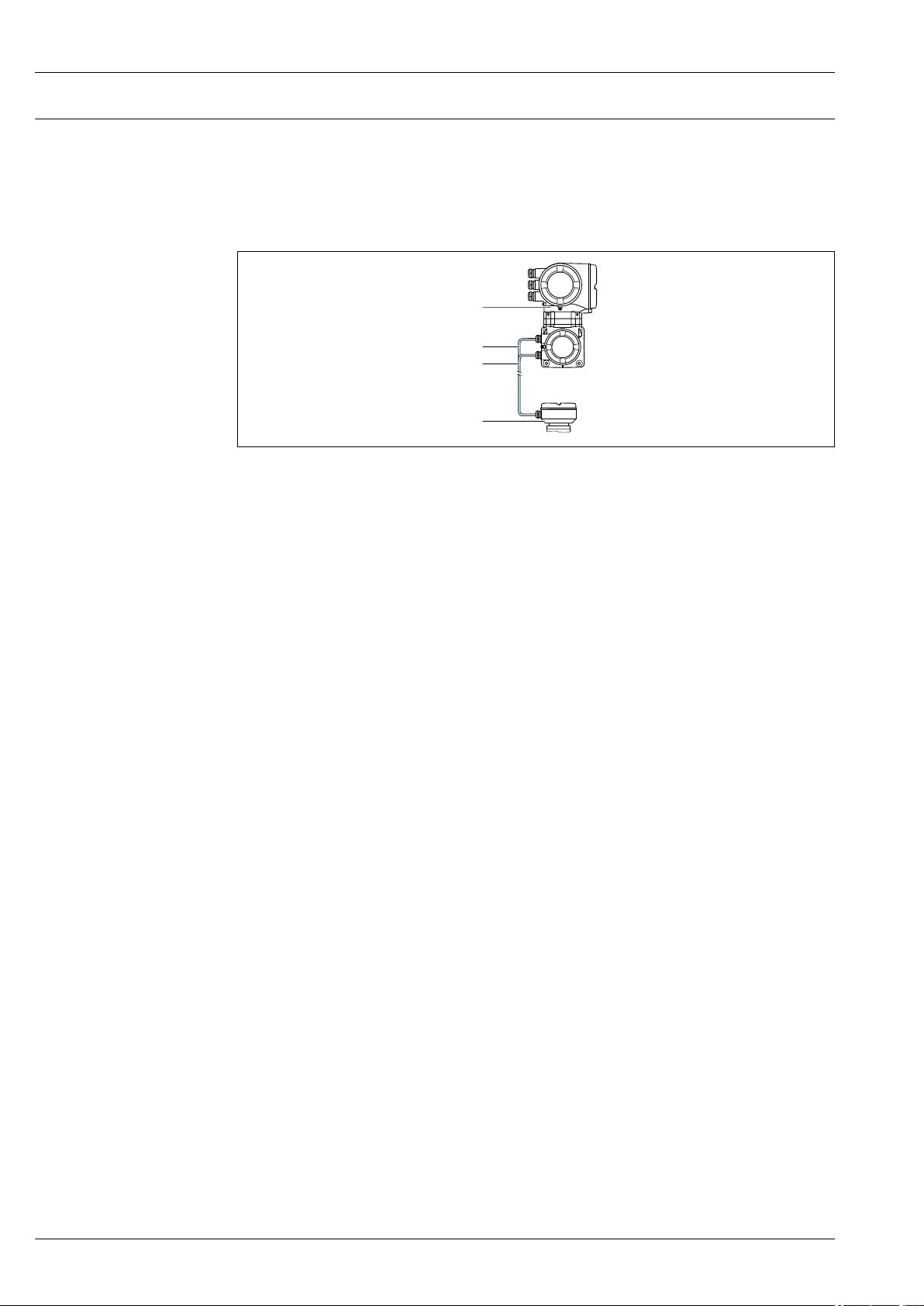
Measuring system
The measuring system consists of a transmitter and a sensor. The transmitter and sensor are
mounted in physically separate locations. They are interconnected by connecting cables.
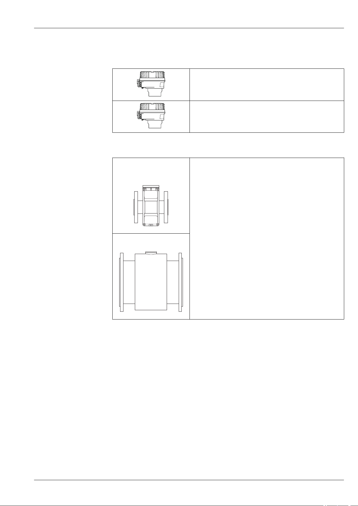
Transmitter
For use in applications required to meet special requirements due to ambient or operating
conditions.
1 Transmitter with integrated ISEM
2 Coil current cable
3 Signal cable
4 Sensor connection housing
Application examples for sensors without electronics:
• Strong vibrations at the sensor.
• Sensor in underground installations.
• Permanent immersion of sensor in water, IP68 ingress protection.
• Electronics and ISEM (intelligent sensor electronics module) in the transmitter housing.
• Signal transmission: analog
Order code for "Integrated ISEM electronics", option B: transmitter
Connecting cable
Connecting cables can be ordered in various lengths → 110 )
• Length: max. 200 m (656 ft), depending on medium conductivity
• Two connecting cables:
– One cable for coil current with a common shield (1 pair)
– One cable for signal transmission with a common shield and individual shielded cores (2 pairs)
Ex Zone
Use in: Ex Zone 1 and 2; Class 1, Division 2 and Class 1, Division 1
Device versions and materials
• Transmitter housing
Aluminum, coated: aluminum, AlSi10Mg, coated
• Window material: glass
Configuration
• External operation via 4-line, backlit, graphic local display with touch control and guided menus
("Make-it-run" wizards) for application-specific commissioning.
• Via service interface or WLAN connection:
– Operating tools (e.g. FieldCare, DeviceCare, SmartBlue app)
– Web server (access via Web browser, e.g. Microsoft Internet Explorer, Microsoft Edge)
6 Endress+Hauser
Page 7
Proline Promag W 500
Sensor connection housing
Different versions of the connection housing are available.
Order code for "Sensor connection housing", option A, "Aluminum, coated":
Aluminum, AlSi10Mg, coated
Order code for "Sensor connection housing", option D, "Polycarbonate":
Polycarbonate
Sensor
Promag W • Nominal diameter range: DN 25 to 2000 (1 to 78")
A0017040
• Materials:
– Sensor housing: aluminum, AlSi10Mg, coated; carbon steel with
protective varnish
– Sensor connection housing (standard): aluminum, AlSi10Mg, coated
Sensor connection housing (option): polycarbonate
– Measuring tubes
1)
:
DN 25 to 600 (1 to 24"): stainless steel, 1.4301/1.4306/304/304L
DN 700 to 2000 (28 to 78"): stainless steel, 1.4301/304
– Liner: hard rubber, polyurethane
– Electrodes: stainless steel, 1.4435 (316L); Alloy C22, 2.4602 (UNS
N06022); tantalum
– Process connections:
Stainless steel, 1.4404/1.4571/F316L
Carbon steel, A105/A181/A350LF2/A515(70)/FE410WB/
S235JRG2/S235J+N/S275JR/P235GH/P250GH/P265GH
– Seals: as per DIN EN 1514-1 Form IBC
– Ground disks: stainless steel, 1.4435 (316L); Alloy C22, 2.4602
(UNS N06022); tantalum
Fixed flange: DN 25 to 300 (1 to
12")
Fixed flange: DN 350 to 2000 (14
to 78")
A0017041
1) For carbon steel flange material with Al/Zn protective coating (DN 25 to 300 (1 to 12")), protective varnish
(IP68) (DN 50 to 300 (2 to 12")) or protective varnish ≥ DN 350 (14")
Endress+Hauser 7
Page 8
Equipment architecture
2
1
6
5
7
4
3
3
Proline Promag W 500
A0027512
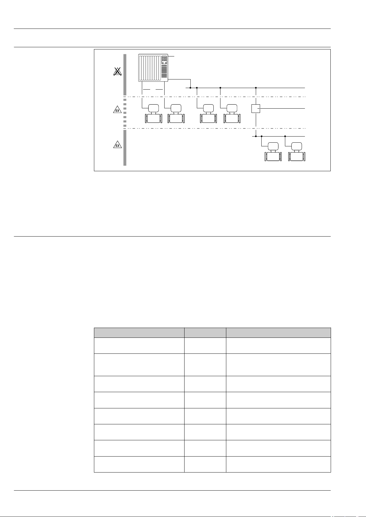
1 Possibilities for integrating measuring devices into a system
1 Control system (e.g. PLC)
2 Connecting cable (0/4 to 20 mA HART etc.)
3 Fieldbus
4 Segment coupler
5 Non-hazardous area
6 Hazardous area: Zone 2; Class I, Division 2
7 Hazardous area: Zone 1; Class I, Division 1
Safety IT security
Our warranty is valid only if the device is installed and used as described in the Operating
Instructions. The device is equipped with security mechanisms to protect it against any inadvertent
changes to the settings.
IT security measures, which provide additional protection for the device and associated data transfer,
must be implemented by the operators themselves in line with their security standards.
Device-specific IT security
The device offers a range of specific functions to support protective measures on the operator's side.
These functions can be configured by the user and guarantee greater in-operation safety if used
correctly. An overview of the most important functions is provided in the following section.
Function/interface Factory setting Recommendation
Write protection via hardware write
protection switch → 9
Access code
(also applies for Web server login or
FieldCare connection) → 9
WLAN
(order option in display module)
WLAN security mode Enabled (WPA2-
WLAN passphrase
(password) → 9
WLAN mode Access Point On an individual basis following risk
Web server→ 9 Enabled. On an individual basis following risk
CDI-RJ45 service interface → 10 – On an individual basis following risk
Not enabled. On an individual basis following risk
assessment.
Not enabled
(0000).
Enabled. On an individual basis following risk
PSK)
Serial number Assign a customized access code during
Assign a customized access code during
commissioning.
assessment.
Do not change.
commissioning.
assessment.
assessment.
assessment.
8 Endress+Hauser
Page 9

Proline Promag W 500
Protecting access via hardware write protection
Write access to the device parameters via the local display, Web browser or operating tool (e.g.
FieldCare, DeviceCare) can be disabled via a write protection switch (DIP switch on the
motherboard). When hardware write protection is enabled, only read access to the parameters is
possible.
Hardware write protection is disabled when the device is delivered.
Protecting access via a password
Different passwords are available to protect write access to the device parameters or access to the
device via the WLAN interface.
• User-specific access code
Protect write access to the device parameters via the local display, Web browser or operating tool
(e.g. FieldCare, DeviceCare). Access authorization is clearly regulated through the use of a userspecific access code.
• WLAN passphrase
The network key protects a connection between an operating unit (e.g. notebook or tablet) and the
device via the WLAN interface which can be ordered as an option.
• Infrastructure mode
When the device is operated in infrastructure mode, the WLAN passphrase corresponds to the
WLAN passphrase configured on the operator side.
User-specific access code
Write access to the device parameters via the local display, Web browser or operating tool (e.g.
FieldCare, DeviceCare) can be protected by the modifiable, user-specific access code.
WLAN passphrase: Operation as WLAN access point
A connection between an operating unit (e.g. notebook or tablet) and the device via the WLAN
interface, which can be ordered as an optional extra, is protected by the network key. The WLAN
authentication of the network key complies with the IEEE 802.11 standard.
When the device is delivered, the network key is pre-defined depending on the device. It can be
changed via the WLAN settings submenu in the WLAN passphrase parameter.
Infrastructure mode
A connection between the device and WLAN access point is protected by means of an SSID and
passphrase on the system side. Please contact the relevant system administrator for access.
General notes on the use of passwords
• The access code and network key supplied with the device should be changed during
commissioning.
• Follow the general rules for generating a secure password when defining and managing the access
code or network key.
• The user is responsible for the management and careful handling of the access code and network
key.
Access via Web server
The device can be operated and configured via a Web browser with the integrated Web server. The
connection is via the service interface (CDI-RJ45) or the WLAN interface. For device versions with
the EtherNet/IP and PROFINET communication protocols, the connection can also be established via
the terminal connection for signal transmission with EtherNet/IP or PROFINET (RJ45 connector).
The Web server is enabled when the device is delivered. The Web server can be disabled if necessary
(e.g. after commissioning) via the Web server functionality parameter.
The device and status information can be hidden on the login page. This prevents unauthorized
access to the information.
For detailed information on device parameters, see:
The "Description of Device Parameters" document → 113
Access via OPC-UA
The "OPC UA Server" application package is available in the device version with the HART
communication protocol → 110.
Endress+Hauser 9
Page 10

Proline Promag W 500
The device can communicate with OPC UA clients using the "OPC UA Server" application package.
The OPC UA server integrated in the device can be accessed via the WLAN access point using the
WLAN interface - which can be ordered as an optional extra - or the service interface (CDI- RJ45) via
Ethernet network. Access rights and authorization as per separate configuration.
The following Security Modes are supported as per the OPC UA Specification (IEC 62541):
• None
• Basic128Rsa15 – signed
• Basic128Rsa15 – signed and encrypted
Access via service interface (CDI-RJ45)
The device can be connected to a network via the service interface (CDI-RJ45). Device-specific
functions guarantee the secure operation of the device in a network.
The use of relevant industrial standards and guidelines that have been defined by national and
international safety committees, such as IEC/ISA62443 or the IEEE, is recommended. This includes
organizational security measures such as the assignment of access authorization as well as technical
measures such as network segmentation.
The device can be integrated in a ring topology. The device is integrated via the terminal
connection for signal transmission (output 1) and the connection to the service interface (CDIRJ45) → 99.
Input
Measured variable Direct measured variables
• Volume flow (proportional to induced voltage)
• Electrical conductivity
Calculated measured variables
Mass flow
Measuring range
Typically v = 0.01 to 10 m/s (0.03 to 33 ft/s) with the specified accuracy
Electrical conductivity: ≥ 5 μS/cm for liquids in general
Flow characteristic values in SI units: DN 25 to 125 (1 to 4")
Nominal
diameter
[mm] [in] [dm3/min] [dm3/min] [dm3] [dm3/min]
25 1 9 to 300 75 0.5 1
32 – 15 to 500 125 1 2
40 1 ½ 25 to 700 200 1.5 3
50 2 35 to 1 100 300 2.5 5
65 – 60 to 2 000 500 5 8
80 3 90 to 3 000 750 5 12
100 4 145 to 4 700 1 200 10 20
125 – 220 to 7 500 1 850 15 30
Recommended
min./max. full scale value
(v ~ 0.3/10 m/s)
flow
Factory settings
Full scale value current
output
(v ~ 2.5 m/s)
Pulse value
(~ 2 pulse/s)
Low flow cut off
(v ~ 0.04 m/s)
10 Endress+Hauser
Page 11

Proline Promag W 500
Flow characteristic values in SI units: DN 150 to 2000 (6 to 78")
Nominal
diameter
[mm] [in] [m3/h] [m3/h] [m3] [m3/h]
150 6 20 to 600 150 0.025 2.5
200 8 35 to 1 100 300 0.05 5
250 10 55 to 1 700 500 0.05 7.5
300 12 80 to 2 400 750 0.1 10
350 14 110 to 3 300 1 000 0.1 15
375 15 140 to 4 200 1 200 0.15 20
400 16 140 to 4 200 1 200 0.15 20
450 18 180 to 5 400 1 500 0.25 25
500 20 220 to 6 600 2 000 0.25 30
600 24 310 to 9 600 2 500 0.3 40
700 28 420 to 13 500 3 500 0.5 50
750 30 480 to 15 000 4 000 0.5 60
800 32 550 to 18 000 4 500 0.75 75
900 36 690 to 22 500 6 000 0.75 100
1 000 40 850 to 28 000 7 000 1 125
– 42 950 to 30 000 8 000 1 125
1 200 48 1 250 to 40 000 10 000 1.5 150
– 54 1 550 to 50 000 13 000 1.5 200
1 400 – 1 700 to 55 000 14 000 2 225
– 60 1 950 to 60 000 16 000 2 250
1 600 – 2 200 to 70 000 18 000 2.5 300
– 66 2 500 to 80 000 20 500 2.5 325
1 800 72 2 800 to 90 000 23 000 3 350
– 78 3 300 to 100 000 28 500 3.5 450
2 000 – 3 400 to 110 000 28 500 3.5 450
Recommended
flow
min./max. full scale value
(v ~ 0.3/10 m/s)
Factory settings
Full scale value current
output
(v ~ 2.5 m/s)
Pulse value
(~ 2 pulse/s)
Low flow cut off
(v ~ 0.04 m/s)
Flow characteristic values in US units
Nominal
diameter
[in] [mm] [gal/min] [gal/min] [gal] [gal/min]
1 25 2.5 to 80 18 0.2 0.25
– 32 4 to 130 30 0.2 0.5
1 ½ 40 7 to 190 50 0.5 0.75
2 50 10 to 300 75 0.5 1.25
– 65 16 to 500 130 1 2
3 80 24 to 800 200 2 2.5
Recommended
flow
min./max. full scale value
(v ~ 0.3/10 m/s)
Factory settings
Full scale value current
output
(v ~ 2.5 m/s)
Pulse value
(~ 2 pulse/s)
Low flow cut off
(v ~ 0.04 m/s)
Endress+Hauser 11
Page 12

Proline Promag W 500
Nominal
diameter
[in] [mm] [gal/min] [gal/min] [gal] [gal/min]
4 100 40 to 1 250 300 2 4
– 125 60 to 1 950 450 5 7
6 150 90 to 2 650 600 5 12
8 200 155 to 4 850 1 200 10 15
10 250 250 to 7 500 1 500 15 30
12 300 350 to 10 600 2 400 25 45
14 350 500 to 15 000 3 600 30 60
15 375 600 to 19 000 4 800 50 60
16 400 600 to 19 000 4 800 50 60
18 450 800 to 24 000 6 000 50 90
20 500 1 000 to 30 000 7 500 75 120
24 600 1 400 to 44 000 10 500 100 180
28 700 1 900 to 60 000 13 500 125 210
30 750 2 150 to 67 000 16 500 150 270
32 800 2 450 to 80 000 19 500 200 300
36 900 3 100 to 100 000 24 000 225 360
40 1 000 3 800 to 125 000 30 000 250 480
42 – 4 200 to 135 000 33 000 250 600
48 1 200 5 500 to 175 000 42 000 400 600
54 – 9 to 300 Mgal/d 75 Mgal/d 0.0005 Mgal/d 1.3 Mgal/d
– 1 400 10 to 340 Mgal/d 85 Mgal/d 0.0005 Mgal/d 1.3 Mgal/d
60 – 12 to 380 Mgal/d 95 Mgal/d 0.0005 Mgal/d 1.3 Mgal/d
– 1 600 13 to 450 Mgal/d 110 Mgal/d 0.0008 Mgal/d 1.7 Mgal/d
66 – 14 to 500 Mgal/d 120 Mgal/d 0.0008 Mgal/d 2.2 Mgal/d
72 1 800 16 to 570 Mgal/d 140 Mgal/d 0.0008 Mgal/d 2.6 Mgal/d
78 – 18 to 650 Mgal/d 175 Mgal/d 0.0010 Mgal/d 3.0 Mgal/d
– 2 000 20 to 700 Mgal/d 175 Mgal/d 0.0010 Mgal/d 2.9 Mgal/d
Recommended
flow
min./max. full scale value
(v ~ 0.3/10 m/s)
Factory settings
Full scale value current
output
(v ~ 2.5 m/s)
Pulse value
(~ 2 pulse/s)
Low flow cut off
(v ~ 0.04 m/s)
To calculate the measuring range, use the Applicator sizing tool → 112
Recommended measuring range
"Flow limit" section → 56
Operable flow range
Over 1000 : 1
Input signal Input and output versions
→ 14
12 Endress+Hauser
Page 13

Proline Promag W 500
External measured values
To increase the accuracy of certain measured variables or to calculate the corrected volume flow, the
automation system can continuously write different measured values to the measuring device:
• Medium temperature to increase the accuracy of the electrical conductivity (e.g. iTEMP)
• Reference density for calculating the corrected volume flow
Various pressure transmitters and temperature measuring devices can be ordered from Endress
+Hauser: see "Accessories" section → 112
It is recommended to read in external measured values to calculate the corrected volume flow.
HART protocol
The measured values are written from the automation system to the measuring device via the HART
protocol. The pressure transmitter must support the following protocol-specific functions:
• HART protocol
• Burst mode
Current input
The measured values are written from the automation system to the measuring device via the
current input → 13.
Digital communication
The measured values can be written from the automation system to the measuring via:
• FOUNDATION Fieldbus
• PROFIBUS DP
• PROFIBUS PA
• Modbus RS485
• EtherNet/IP
• PROFINET
Current input 0/4 to 20 mA
Current input 0/4 to 20 mA (active/passive)
Current span • 4 to 20 mA (active)
• 0/4 to 20 mA (passive)
Resolution 1 µA
Voltage drop Typically: 0.6 to 2 V for 3.6 to 22 mA (passive)
Maximum input voltage ≤ 30 V (passive)
Open-circuit voltage ≤ 28.8 V (active)
Possible input variables • Pressure
• Temperature
• Density
Status input
Maximum input values • DC –3 to 30 V
• If status input is active (ON): Ri >3 kΩ
Response time Adjustable: 5 to 200 ms
Input signal level • Low signal: DC –3 to +5 V
• High signal: DC 12 to 30 V
Assignable functions • Off
• Reset the individual totalizers separately
• Reset all totalizers
• Flow override
Endress+Hauser 13
Page 14
Output
Proline Promag W 500
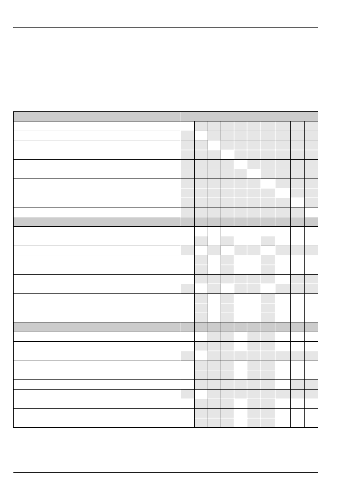
Output and input variants
Depending on the option selected for output/input 1, different options are available for the other
outputs and inputs. Only one option can be selected for each output/input 1 to 4. The table must be
read vertically (↓).
Example: If the option BA "4–20 mA HART" was selected for output/input 1, one of the options A, B,
D, E, F, H, I or J is available for output 2, and one of the options A, B, D, E, F, H, I or J is available for
output 3 and 4.
Order code for "Output; input 1" (020) → Possible options
Current output 4 to 20 mA HART BA
Current output 4 to 20 mA HART Ex i ↓ CA
FOUNDATION Fieldbus ↓ SA
FOUNDATION Fieldbus Ex i ↓ TA
PROFIBUS DP ↓ LA
PROFIBUS PA ↓ GA
PROFIBUS PA Ex i ↓ HA
Modbus RS485 ↓ MA
EtherNet/IP 2-port switch integrated ↓ NA
PROFINET 2-port switch integrated ↓ RA
Order code for "Output; input 2" (021) → ↓ ↓ ↓ ↓ ↓ ↓ ↓ ↓ ↓ ↓
Not assigned A A A A A A A A A A
Current output 0/4 to 20 mA B B B B B B B
Current output 0/4 to 20 mA (Ex i) C C C
User configurable input/output
Pulse/frequency/switch output E E E E E E E
Double pulse output
Pulse/frequency/switch output (Ex i) G G G
Relay output H H H H H H H
Current input 0/4 to 20 mA I I I I I I I
Status input J J J J J J J
Order code for "Output; input 3" (022) → ↓ ↓ ↓ ↓ ↓ ↓ ↓ ↓ ↓ ↓
Not assigned A A A A A A A A A A
Current output 0/4 to 20 mA B B B B B
Current output 0/4 to 20 mA (Ex i) C
User configurable input/output D D D D D
Pulse/frequency/switch output E E E E E
Double pulse output (slave)
Pulse/frequency/switch output (Ex i) G
Relay output H H H H H
Current input 0/4 to 20 mA I I I I I
Status input J J J J J
2)
1)
3)
D D D D D D D
F F
F F
1) A specific input or output can be assigned to a user configurable input/output → 18.
2) If double pulse output (F) is selected for output/input 2 (021), only the double pulse output (F) option is available for selection for output/input 3
(022).
3) The double pulse output (F) option is not available for input/output 4.
14 Endress+Hauser
Page 15
Proline Promag W 500
Output signal HART current output
Current output 4 to 20 mA HART
Current span Can be set to: 4 to 20 mA (active/passive)
Open-circuit voltage DC 28.8 V (active)
Maximum input voltage DC 30 V (passive)
Load 250 to 700 Ω
Resolution 0.38 µA
Damping Configurable: 0.07 to 999 s
Assignable measured
variables
Ex-i, passive
• Volume flow
• Mass flow
• Corrected volume flow
• Flow velocity
• Conductivity
• Corrected conductivity
• Electronic temperature
PROFIBUS PA
PROFIBUS PA In accordance with EN 50170 Volume 2, IEC 61158-2 (MBP), galvanically
isolated
Data transmission 31.25 kbit/s
Current consumption 10 mA
16 mA
Permitted supply voltage 9 to 32 V
Bus connection With integrated reverse polarity protection
PROFIBUS DP
Signal encoding NRZ code
Data transfer 9.6 kBaud…12 MBaud
EtherNet/IP
Standards In accordance with IEEE 802.3
PROFINET
Standards In accordance with IEEE 802.3
FOUNDATION Fieldbus
FOUNDATION Fieldbus H1, IEC 61158-2, galvanically isolated
Data transfer 31.25 kbit/s
Current consumption 10 mA
Permitted supply voltage 9 to 32 V
Bus connection With integrated reverse polarity protection
Endress+Hauser 15
Page 16
Modbus RS485
Physical interface RS485 in accordance with EIA/TIA-485 standard
Terminating resistor Integrated, can be activated via DIP switches
Current output 0/4 to 20 mA
Current output 0/4 to 20 mA
Maximum output values 22.5 mA
Current span Can be set to:
• 4 to 20 mA (active)
• 0/4 to 20 mA (passive)
Ex-i, passive
Open-circuit voltage DC 28.8 V (active)
Maximum input voltage DC 30 V (passive)
Load 0 to 700 Ω
Resolution 0.38 µA
Damping Adjustable: 0.07 to 999 s
Assignable measured
variables
• Volume flow
• Mass flow
• Corrected volume flow
• Flow velocity
• Conductivity
• Corrected conductivity
• Temperature
• Electronic temperature
Proline Promag W 500
Pulse/frequency/switch output
Function Can be set to pulse, frequency or switch output
Version Open collector
Can be set to:
• Active
• Passive
Ex-i, passive
Maximum input values DC 30 V, 250 mA (passive)
Open-circuit voltage DC 28.8 V (active)
Voltage drop For 22.5 mA: ≤ DC 2 V
Pulse output
Maximum input values DC 30 V, 250 mA (passive)
Maximum output current 22.5 mA (active)
Open-circuit voltage DC 28.8 V (active)
Pulse width Adjustable: 0.05 to 2 000 ms
Maximum pulse rate 10 000 Impulse/s
Pulse value Adjustable
Assignable measured
variables
Frequency output
• Volume flow
• Mass flow
• Corrected volume flow
16 Endress+Hauser
Page 17
Proline Promag W 500
Maximum input values DC 30 V, 250 mA (passive)
Maximum output current 22.5 mA (active)
Open-circuit voltage DC 28.8 V (active)
Output frequency Adjustable: end value frequency 2 to 10 000 Hz (f
Damping Adjustable: 0 to 999 s
Pulse/pause ratio 1:1
Assignable measured
variables
Switch output
Maximum input values DC 30 V, 250 mA (passive)
Open-circuit voltage DC 28.8 V (active)
Switching behavior Binary, conductive or non-conductive
Switching delay Adjustable: 0 to 100 s
Number of switching
cycles
Assignable functions • Off
• Volume flow
• Mass flow
• Corrected volume flow
• Flow velocity
• Conductivity
• Corrected conductivity
• Temperature
• Electronic temperature
Unlimited
• On
• Diagnostic behavior
• Limit value:
– Off
– Volume flow
– Mass flow
– Corrected volume flow
– Flow velocity
– Conductivity
– Corrected conductivity
– Totalizer 1-3
– Temperature
– Electronic temperature
• Flow direction monitoring
• Status
– Empty pipe detection
– Low flow
= 12 500 Hz)
max
Double pulse output
Function Double pulse
Version Open collector
Can be set to:
• Active
• Passive
Maximum input values DC 30 V, 250 mA (passive)
Open-circuit voltage DC 28.8 V (active)
Voltage drop For 22.5 mA: ≤ DC 2 V
Output frequency Adjustable: 0 to 1 000 Hz
Damping Adjustable: 0 to 999 s
Endress+Hauser 17
Page 18

Pulse/pause ratio 1:1
Assignable measured
variables
• Volume flow
• Mass flow
• Corrected volume flow
• Flow velocity
• Conductivity
• Corrected conductivity
• Temperature
• Electronic temperature
Relay output
Function Switch output
Version Relay output, galvanically isolated
Switching behavior Can be set to:
• NO (normally open), factory setting
• NC (normally closed)
Maximum switching
capacity (passive)
Assignable functions • Off
• DC 30 V, 0.1 A
• AC 30 V, 0.5 A
• On
• Diagnostic behavior
• Limit value:
– Off
– Volume flow
– Mass flow
– Corrected volume flow
– Flow velocity
– Conductivity
– Corrected conductivity
– Totalizer 1-3
– Temperature
– Electronic temperature
• Flow direction monitoring
• Status
– Empty pipe detection
– Low flow
Proline Promag W 500
User configurable input/output
One specific input or output is assigned to a user-configurable input/output (configurable I/O)
during device commissioning.
The following inputs and outputs are available for assignment:
• Choice of current output: 4 to 20 mA (active), 0/4 to 20 mA (passive)
• Pulse/frequency/switch output
• Choice of current input: 4 to 20 mA (active), 0/4 to 20 mA (passive)
• Status input
The technical values correspond to those of the inputs and outputs described in this section.
Signal on alarm
Depending on the interface, failure information is displayed as follows:
HART current output
Device diagnostics Device condition can be read out via HART Command 48
18 Endress+Hauser
Page 19

Proline Promag W 500
PROFIBUS PA
Status and alarm
messages
Error current FDE (Fault
Disconnection Electronic)
Diagnostics in accordance with PROFIBUS PA Profile 3.02
0 mA
PROFIBUS DP
Status and alarm
messages
Diagnostics in accordance with PROFIBUS PA Profile 3.02
EtherNet/IP
Device diagnostics Device condition can be read out in Input Assembly
PROFINET
Device diagnostics According to "Application Layer protocol for decentralized periphery", Version 2.3
FOUNDATION Fieldbus
Status and alarm
messages
Error current FDE (Fault
Disconnection Electronic)
Diagnostics in accordance with FF-891
0 mA
Modbus RS485
Failure mode Choose from:
• NaN value instead of current value
• Last valid value
Current output 0/4 to 20 mA
4 to 20 mA
Failure mode Choose from:
• 4 to 20 mA in accordance with NAMUR recommendation NE 43
• 4 to 20 mA in accordance with US
• Min. value: 3.59 mA
• Max. value: 22.5 mA
• Freely definable value between: 3.59 to 22.5 mA
• Actual value
• Last valid value
0 to 20 mA
Failure mode Choose from:
• Maximum alarm: 22 mA
• Freely definable value between: 0 to 20.5 mA
Endress+Hauser 19
Page 20
Pulse/frequency/switch output
Pulse output
Failure mode Choose from:
• Actual value
• No pulses
Frequency output
Failure mode Choose from:
• Actual value
• 0 Hz
• Defined value (f
Switch output
Failure mode Choose from:
• Current status
• Open
• Closed
Relay output
Failure mode Choose from:
• Current status
• Open
• Closed
2 to 12 500 Hz)
max
Proline Promag W 500
Local display
Plain text display With information on cause and remedial measures
Backlight Red backlighting indicates a device error.
Status signal as per NAMUR recommendation NE 107
Interface/protocol
• Via digital communication:
– HART protocol
– FOUNDATION Fieldbus
– PROFIBUS PA
– PROFIBUS DP
– Modbus RS485
– EtherNet/IP
– PROFINET
• Via service interface
– CDI-RJ45 service interface
– WLAN interface
Plain text display With information on cause and remedial measures
Additional information on remote operation → 95
Web server
Plain text display With information on cause and remedial measures
20 Endress+Hauser
Page 21
Proline Promag W 500
Light emitting diodes (LED)
Status information Status indicated by various light emitting diodes
Ex connection data Safety-related values
The following information is displayed depending on the device version:
• Supply voltage active
• Data transmission active
• Device alarm/error has occurred
• EtherNet/IP network available
• EtherNet/IP connection established
• PROFINET network available
• PROFINET connection established
• PROFINET blinking feature
Order code for
Output type Safety-related values
"Output; input 1"
Option BA Current output
4 to 20 mA HART
UN = 30 V
UM = 250 V
Option GA PROFIBUS PA UN = 30 V
UM = 250 V
Option LA PROFIBUS DP UN = 30 V
UM = 250 V
Option MA Modbus RS485 UN = 30 V
UM = 250 V
Option SA FOUNDATION Fieldbus UN = 30 V
UM = 250 V
Option NA EtherNet/IP UN = 30 V
UM = 250 V
Option RA PROFINET UN = 30 V
UM = 250 V
Order code for
"Output; input 2";
"Output; input 3"
Output type Safety-related values
Output; input 2 Output; input 3
24 (+) 25 (–) 22 (+) 23 (–)
Option B Current output
4 to 20 mA
Option D User configurable input/
output
Option E Pulse/frequency/switch
output
UN = 30 V
UM = 250 V
UN = 30 V
UM = 250 V
UN = 30 V
UM = 250 V
Option F Double pulse output UN = 30 V
UM = 250 V
Option H Relay output UN = 30 V
IN =100 mADC/500 mA
UM = 250 V
Option I Current input 4 to 20 mA UN = 30 V
UM = 250 V
Option J Status input UN = 30 V
UM = 250 V
"Output; input 1"
26 (+) 27 (–)
DC
AC
DC
AC
DC
AC
DC
AC
DC
AC
DC
AC
DC
AC
DC
AC
DC
AC
DC
AC
DC
AC
DC
AC
AC
DC
AC
DC
AC
Endress+Hauser 21
Page 22
Intrinsically safe values
Proline Promag W 500
Order code for
"Output; input 1"
Option CA Current output
Option HA PROFIBUS PA Ex i Ex ia
Option TA FOUNDATION Fieldbus
1) Only available for the Zone 1; Class I, Division 1 version
Order code for
"Output; input 2";
"Output; input 3"
Option C Current output
Option G Pulse/frequency/switch
Output type Intrinsically safe values
Ui = 30 V
4 to 20 mA HART Ex i
Ex i
Output type Intrinsically safe values or NIFW values
4 to 20 mA Ex i
output Ex i
li = 100 mA
Pi = 1.25 W
Li = 0
Ci = 0
Ui = 30 V
li = 570 mA
Pi = 8.5 W
Li = 10 µH
Ci = 5 nF
Ex ia
Ui = 30 V
li = 570 mA
Pi = 8.5 W
Li = 10 µH
Ci = 5 nF
Ui = 30 V
li = 100 mA
Pi = 1.25 W
Li = 0
Ci = 0
Ui = 30 V
li = 100 mA
Pi = 1.25 W
Li = 0
Ci = 0
"Output; input 1"
26 (+) 27 (–)
1)
Output; input 2 Output; input 3
24 (+) 25 (–) 22 (+) 23 (–)
Low flow cut off
Galvanic isolation
The switch points for low flow cut off are user-selectable.
The outputs are galvanically isolated from one another and from earth (PE).
Protocol-specific data HART
Manufacturer ID 0x11
Device type ID 0x3C
HART protocol revision 7
Device description files
(DTM, DD)
HART load Min. 250 Ω
System integration Information on system integration: Operating Instructions → 113.
Information and files under:
www.endress.com
• Measured variables via HART protocol
• Burst Mode functionality
22 Endress+Hauser
Page 23

Proline Promag W 500
PROFIBUS PA
Manufacturer ID 0x11
Ident number 0x156C
Profile version 3.02
Device description files (GSD,
DTM, DD)
Supported functions • Identification & Maintenance
Configuration of the device
address
Compatibility with
earlier model
System integration Information regarding system integration: Operating Instructions → 113.
Information and files under:
• www.endress.com
• www.profibus.org
Simplest device identification on the part of the control system and
nameplate
• PROFIBUS upload/download
Reading and writing parameters is up to ten times faster with PROFIBUS
upload/download
• Condensed status
Simplest and self-explanatory diagnostic information by categorizing
diagnostic messages that occur
• DIP switches on the I/O electronics module
• Local display
• Via operating tools (e.g. FieldCare)
If the device is replaced, the measuring device Promag 500 supports the
compatibility of the cyclic data with previous models. It is not necessary to
adjust the engineering parameters of the PROFIBUS network with the Promag
500 GSD file.
Earlier models:
• Promag 50 PROFIBUS PA
– ID No.: 1525 (hex)
– Extended GSD file: EH3x1525.gsd
– Standard GSD file: EH3_1525.gsd
• Promag 53 PROFIBUS PA
– ID No.: 1527 (hex)
– Extended GSD file: EH3x1527.gsd
– Standard GSD file: EH3_1527.gsd
Description of the function scope of compatibility:
Operating Instructions → 113.
• Cyclic data transmission
• Block model
• Description of the modules
PROFIBUS DP
Manufacturer ID 0x11
Ident number 0x1570
Profile version 3.02
Device description files (GSD,
DTM, DD)
Supported functions • Identification & Maintenance
Information and files under:
• www.endress.com
On the product page for the device: Documents/Software → Device drivers
• www.profibus.org
Simplest device identification on the part of the control system and
nameplate
• PROFIBUS upload/download
Reading and writing parameters is up to ten times faster with PROFIBUS
upload/download
• Condensed status
Simplest and self-explanatory diagnostic information by categorizing
diagnostic messages that occur
Endress+Hauser 23
Page 24

Proline Promag W 500
Configuration of the device
address
System integration Information regarding system integration: Operating Instructions → 113.
• DIP switches on the I/O electronics module
• Via operating tools (e.g. FieldCare)
• Cyclic data transmission
• Block model
• Description of the modules
EtherNet/IP
Protocol • The CIP Networks Library Volume 1: Common Industrial Protocol
• The CIP Networks Library Volume 2: EtherNet/IP Adaptation of CIP
Communication type • 10Base-T
• 100Base-TX
Device profile Generic device (product type: 0x2B)
Manufacturer ID 0x11
Device type ID 0x103C
Baud rates Automatic ¹⁰⁄₁₀₀ Mbit with half-duplex and full-duplex detection
Polarity Auto-polarity for automatic correction of crossed TxD and RxD pairs
Supported CIP connections Max. 3 connections
Explicit connections Max. 6 connections
I/O connections Max. 6 connections (scanner)
Configuration options for
measuring device
Configuration of the EtherNet
interface
Configuration of the device
address
Device Level Ring (DLR) Yes
System integration Information regarding system integration: Operating Instructions
• DIP switches on the electronics module for IP addressing
• Manufacturer-specific software (FieldCare)
• Add-on Profile Level 3 for Rockwell Automation control systems
• Web browser
• Electronic Data Sheet (EDS) integrated in the measuring device
• Speed: 10 MBit, 100 MBit, auto (factory setting)
• Duplex: half-duplex, full-duplex, auto (factory setting)
• DIP switches on the electronics module for IP addressing (last octet)
• DHCP
• Manufacturer-specific software (FieldCare)
• Add-on Profile Level 3 for Rockwell Automation control systems
• Web browser
• EtherNet/IP tools, e.g. RSLinx (Rockwell Automation)
→ 113.
• Cyclic data transmission
• Block model
• Input and output groups
PROFINET
Protocol "Application layer protocol for decentral device periphery and distributed
automation", version 2.3
Communication type 100 MBit/s
Conformity class Conformance Class B
Netload Class Netload Class II
Baud rates Automatic 100 Mbit/s with full-duplex detection
Cycle times From 8 ms
Polarity Auto-polarity for automatic correction of crossed TxD and RxD pairs
24 Endress+Hauser
Page 25

Proline Promag W 500
Media Redundancy Protocol
(MRP)
Device profile Application interface identifier 0xF600
Manufacturer ID 0x11
Device type ID 0x843C
Device description files (GSD,
DTM, DD)
Supported connections • 1 x AR (IO Controller AR)
Configuration options for
measuring device
Configuration of the
device name
Supported functions • Identification & Maintenance
System integration Information regarding system integration: Operating Instructions → 113.
Yes
Generic device
Information and files under:
• www.endress.com
On the product page for the device: Documents/Software → Device drivers
• www.profibus.org
• 1 x AR (IO-Supervisor Device AR connection allowed)
• 1 x Input CR (Communication Relation)
• 1 x Output CR (Communication Relation)
• 1 x Alarm CR (Communication Relation)
• DIP switches on the electronics module, for device name assignment (last
part)
• Manufacturer-specific software (FieldCare, DeviceCare)
• Web browser
• Device master file (GSD), can be read out via the integrated Web server of
the measuring device
• DIP switches on the electronics module, for device name assignment (last
part)
• DCP protocol
• Process Device Manager (PDM)
• Integrated Web server
Simple device identification via:
– Control system
– Nameplate
• Measured value status
The process variables are communicated with a measured value status
• Blinking feature via the onsite display for simple device identification and
assignment
• Device operation via operating tools (e.g. FieldCare, DeviceCare, SIMATIC
PDM)
• Cyclic data transmission
• Overview and description of the modules
• Status coding
• Startup configuration
• Factory setting:
FOUNDATION Fieldbus
Manufacturer ID 0x452B48 (hex)
Ident number 0x103C (hex)
Device revision 1
DD revision Information and files under:
CFF revision
Interoperability Test Kit (ITK) Version 6.2.0
ITK Test Campaign Number Information:
Link Master capability (LAS) Yes
Choice of "Link Master" and
"Basic Device"
• www.endress.com
• www.fieldbus.org
• www.endress.com
• www.fieldbus.org
Yes
Factory setting: Basic Device
Endress+Hauser 25
Page 26

Proline Promag W 500
Node address Factory setting: 247 (0xF7)
Supported functions The following methods are supported:
• Restart
• ENP Restart
• Diagnostic
• Set to OOS
• Set to AUTO
• Read trend data
• Read event logbook
Virtual Communication Relationships (VCRs)
Number of VCRs 44
Number of link objects in VFD 50
Permanent entries 1
Client VCRs 0
Server VCRs 10
Source VCRs 43
Sink VCRs 0
Subscriber VCRs 43
Publisher VCRs 43
Device Link Capabilities
Slot time 4
Min. delay between PDU 8
Max. response delay 16
System integration Information regarding system integration: Operating Instructions → 113.
• Cyclic data transmission
• Description of the modules
• Execution times
• Methods
Modbus RS485
Protocol Modbus Applications Protocol Specification V1.1
Response times • Direct data access: typically 25 to 50 ms
• Auto-scan buffer (data range): typically 3 to 5 ms
Device type Slave
Slave address range 1 to 247
Broadcast address range 0
Function codes • 03: Read holding register
• 04: Read input register
• 06: Write single registers
• 08: Diagnostics
• 16: Write multiple registers
• 23: Read/write multiple registers
Broadcast messages Supported by the following function codes:
• 06: Write single registers
• 16: Write multiple registers
• 23: Read/write multiple registers
26 Endress+Hauser
Page 27
Proline Promag W 500
Supported baud rate • 1 200 BAUD
• 2 400 BAUD
• 4 800 BAUD
• 9 600 BAUD
• 19 200 BAUD
• 38 400 BAUD
• 57 600 BAUD
• 115 200 BAUD
Data transfer mode • ASCII
• RTU
Data access Each device parameter can be accessed via Modbus RS485.
For Modbus register information
Compatibility with
earlier model
System integration Information on system integration: Operating Instructions → 113.
If the device is replaced, the measuring device Promag 500 supports the
compatibility of the Modbus registers for the process variables and the
diagnostic information with the previous model Promag 53. It is not necessary
to change the engineering parameters in the automation system.
Description of the function scope of compatibility:
Operating Instructions → 113.
• Modbus RS485 information
• Function codes
• Register information
• Response time
• Modbus data map
Power supply
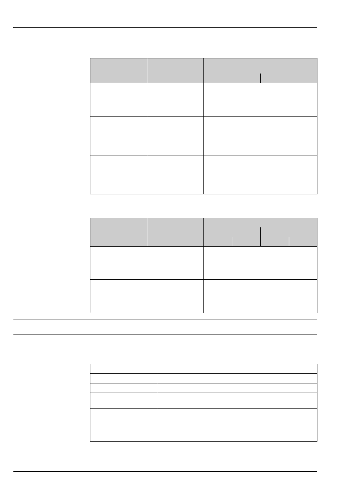
Terminal assignment Transmitter: supply voltage, input/outputs
HART
Supply voltage Input/output 1 Input/output 2 Input/output 3
1 (+) 2 (–) 26 (+) 27 (–) 24 (+) 25 (–) 22 (+) 23 (–)
The terminal assignment depends on the specific device version ordered → 14.
FOUNDATION Fieldbus
Supply voltage Input/output 1 Input/output 2 Input/output 3
1 (+) 2 (–) 26 (A) 27 (B) 24 (+) 25 (–) 22 (+) 23 (–)
The terminal assignment depends on the specific device version ordered → 14.
PROFIBUS PA
Supply voltage Input/output 1 Input/output 2 Input/output 3
1 (+) 2 (–) 26 (B) 27 (A) 24 (+) 25 (–) 22 (+) 23 (–)
The terminal assignment depends on the specific device version ordered → 14.
PROFIBUS DP
Supply voltage Input/output 1 Input/output 2 Input/output 3
1 (+) 2 (–) 26 (B) 27 (A) 24 (+) 25 (–) 22 (+) 23 (–)
The terminal assignment depends on the specific device version ordered → 14.
Endress+Hauser 27
Page 28
Proline Promag W 500
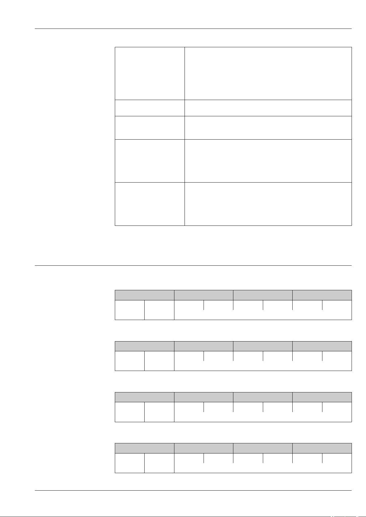
PROFINET
Supply voltage Input/output 1 Input/output 2 Input/output 3
1 (+) 2 (–) PROFINET
(RJ45 connector)
Modbus RS485
Supply voltage Input/output 1 Input/output 2 Input/output 3
1 (+) 2 (–) 26 (B) 27 (A) 24 (+) 25 (–) 22 (+) 23 (–)
The terminal assignment depends on the specific device version ordered → 14.
EtherNet/IP
Supply voltage Input/output 1 Input/output 2 Input/output 3
1 (+) 2 (–) EtherNet/IP
(RJ45 connector)
24 (+) 25 (–) 22 (+) 23 (–)
The terminal assignment depends on the specific
device version ordered → 14.
24 (+) 25 (–) 22 (+) 23 (–)
The terminal assignment depends on the specific
device version ordered → 14.
Device plugs available
Transmitter and sensor connection housing: connecting cable
The sensor and transmitter, which are mounted in separate locations, are interconnected by a
connecting cable. The cable is connected via the sensor connection housing and the transmitter
housing.
Terminal assignment and connection of the connecting cable → 32
Device plugs may not be used in hazardous areas!
Device plugs for fieldbus systems:
Order code for "Input; output 1"
• Option SA "FOUNDATION Fieldbus" → 28
• Option GA "PROFIBUS PA" → 28
• Option RA "PROFINET" → 29
• Option NA "EtherNet/IP" → 29
Device plug for connecting to the service interface:
Order code for "Accessory mounted"
option NB, adapter RJ45 M12 (service interface) → 30
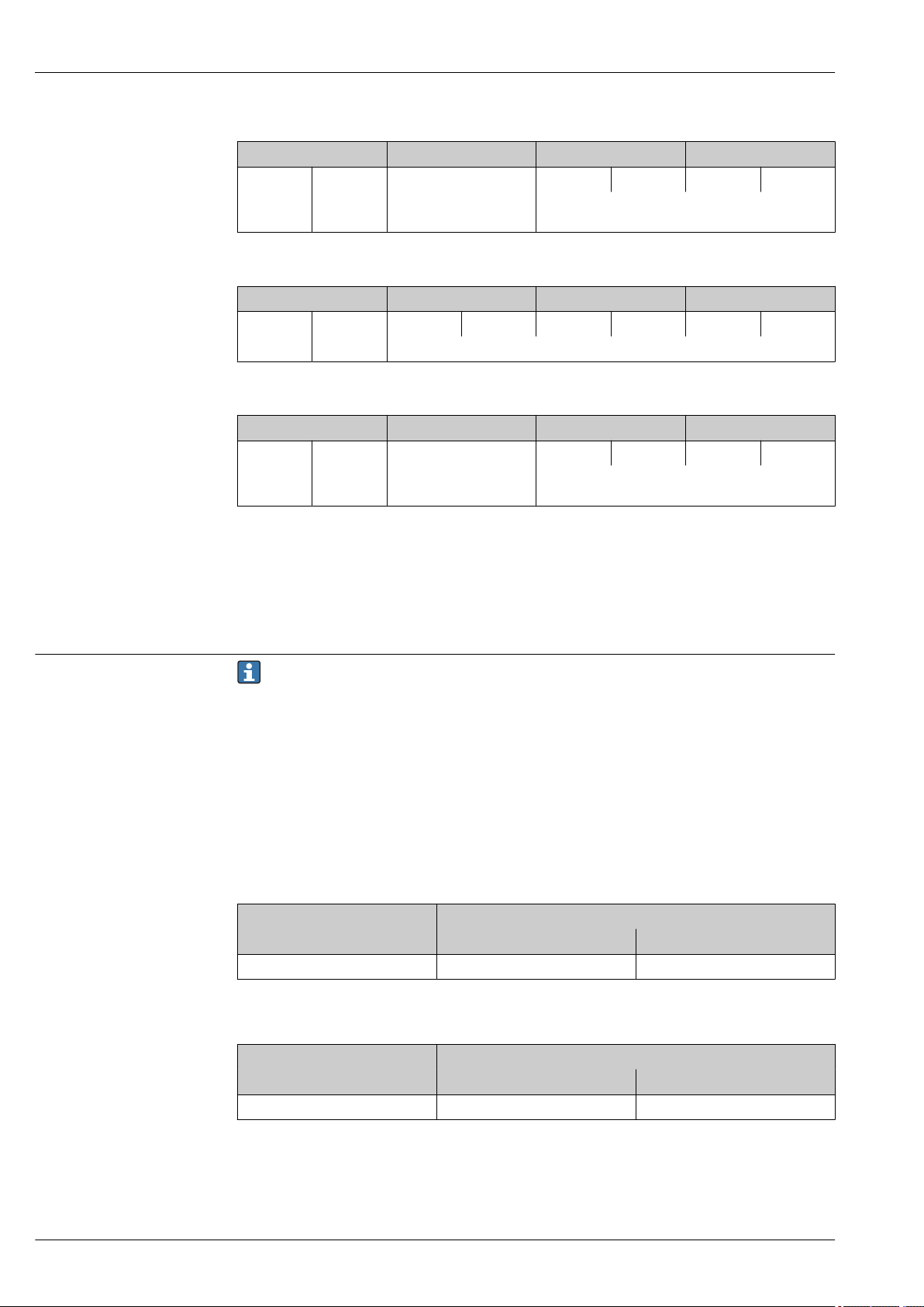
Order code for "Input; output 1", option SA "FOUNDATION Fieldbus"
Order code for Cable entry/connection → 32
"Electrical connection" 2 3
M, 3, 4, 5 7/8" connector –
Order code for "Input; output 1", option GA "PROFIBUS PA"
Order code for Cable entry/connection → 32
"Electrical connection" 2 3
L, N, P, U Connector M12 × 1 –
28 Endress+Hauser
Page 29
Proline Promag W 500
1
2
4
3
1
2
4
3
Order code for "Input; output 1", option RA "PROFINET"
Order code for Cable entry/connection → 32
"Electrical connection" 2 3
L, N, P, U Connector M12 × 1 –
1) 2)
1) 2)
1) 2)
R
, S
, T
, V
1) 2)
Connector M12 × 1 Connector M12 × 1
1) Cannot be combined with an external WLAN antenna (order code for "Enclosed accessories", option P8) of
an RJ45 M12 adapter for the service interface (order code for "Accessories mounted", option NB) or of the
remote display and operating module DKX001.
2) Suitable for integrating the device in a ring topology.
Order code for "Input; output 1", option NA "EtherNet/IP"
Order code for Cable entry/connection → 32
"Electrical connection" 2 3
L, N, P, U Connector M12 × 1 –
1) 2)
1) 2)
1) 2)
R
, S
, T
, V
1) 2)
Connector M12 × 1 Connector M12 × 1
1) Cannot be combined with an external WLAN antenna (order code for "Enclosed accessories", option P8) of
an RJ45 M12 adapter for the service interface (order code for "Accessories mounted", option NB) or of the
remote display and operating module DKX001
2) Suitable for integrating the device in a ring topology.
Order code for "Accessory mounted", option NB "Adapter RJ45 M12 (service interface)"
Order code Cable entry/coupling → 32
"Accessory mounted" Cable entry
NB Plug M12 × 1 –
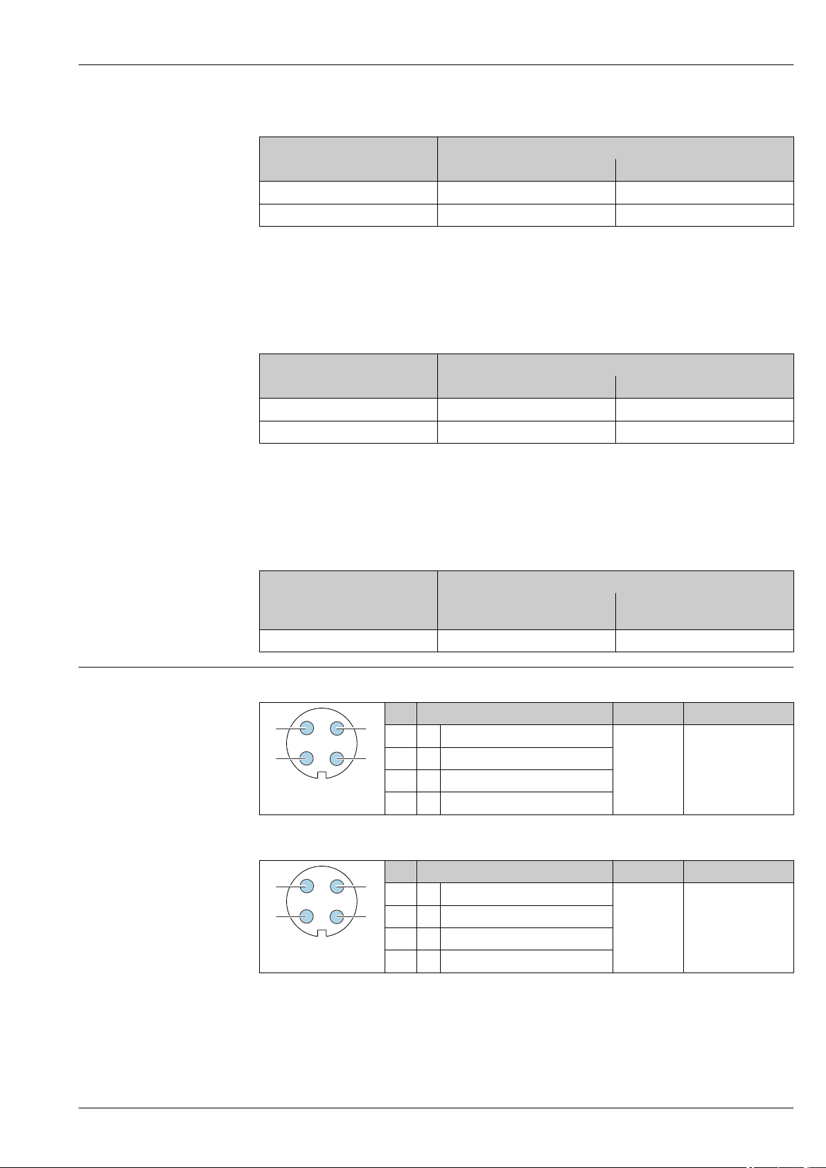
Pin assignment, device plug FOUNDATION Fieldbus
PROFIBUS PA
Cable entry
2
3
Pin Assignment Coding Plug/socket
1 + Signal + A Plug
2 - Signal –
3 Grounding
4 Not assigned
Pin Assignment Coding Plug/socket
1 + PROFIBUS PA + A Plug
2 Grounding
3 - PROFIBUS PA –
4 Not assigned
Endress+Hauser 29
Page 30
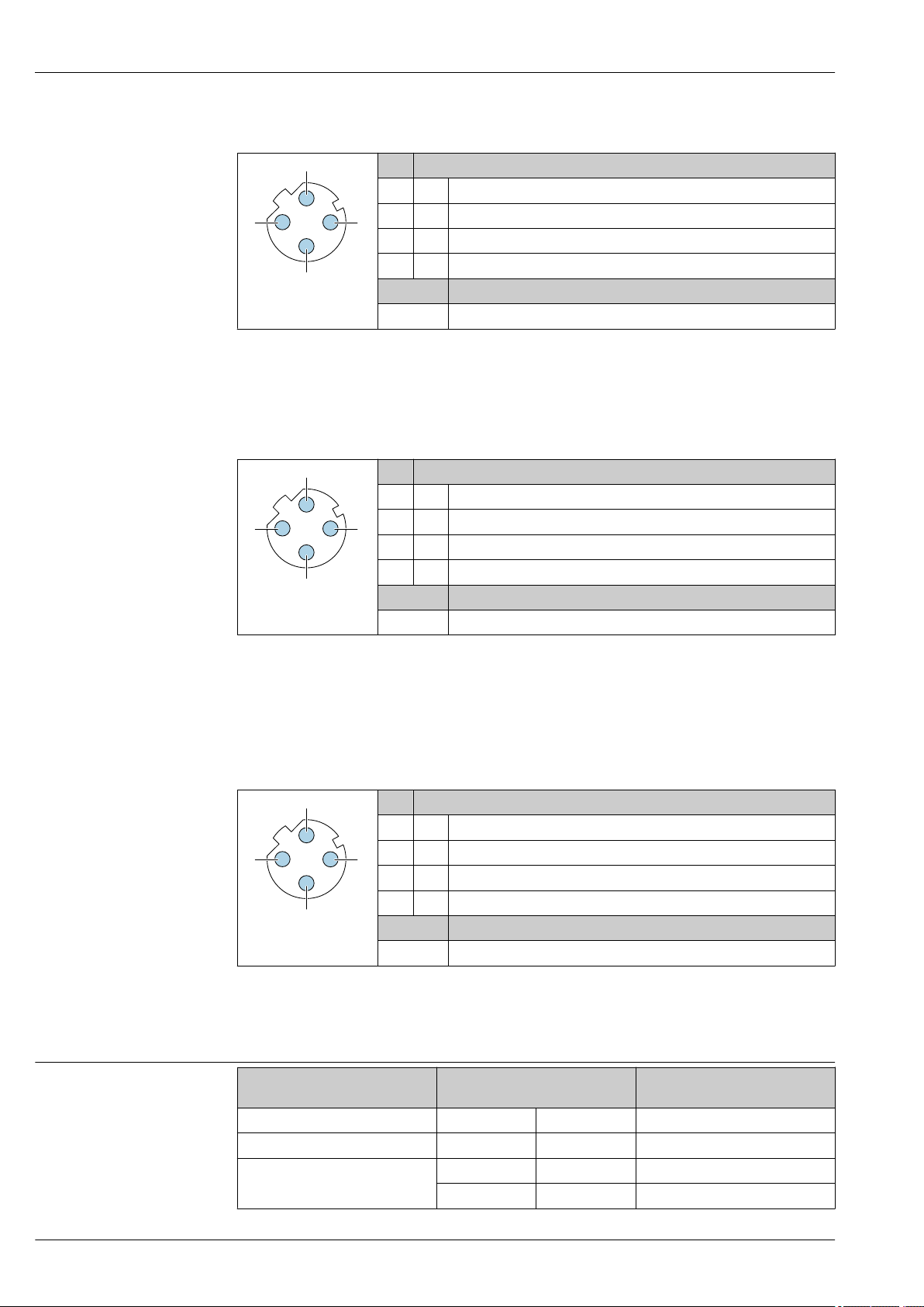
PROFINET
3
2
4
3
2
4
3
2
4
Pin Assignment
1 + TD +
2 + RD +
3 - TD –
4 - RD –
A0032047
Recommended plug:
• Binder, series 763, part no. 99 3729 810 04
• Phoenix, part no. 1543223 SACC-M12MSD-4Q
• When using the device in a hazardous location, use a suitably certified plug.
Coding Plug/socket
D Socket
EtherNet/IP
Pin Assignment
1 + Tx
2 + Rx
3 - Tx
4 - Rx
A0032047
Coding Plug/socket
D Socket
Proline Promag W 500
Supply voltage
Recommended plug:
• Binder, series 763, part no. 99 3729 810 04
• Phoenix, part no. 1543223 SACC-M12MSD-4Q
• When using the device in a hazardous location, use a suitably certified plug.
Service interface
Order code for "Accessories mounted", option NB: Adapter RJ45 M12 (service interface)
Pin Assignment
1 + Tx
2 + Rx
3 - Tx
4 - Rx
A0032047
Recommended plug:
• Binder, series 763, part no. 99 3729 810 04
• Phoenix, part no. 1543223 SACC-M12MSD-4Q
• When using the device in a hazardous location, use a suitably certified plug.
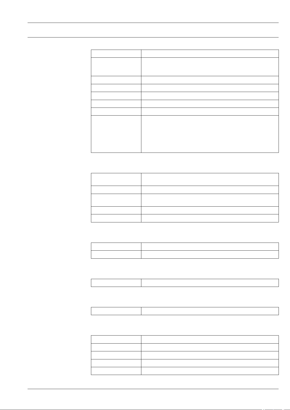
Order code for
"Power supply"
Option D DC24 V ±20% –
Option E AC100 to 240 V –15…+10% 50/60 Hz, ±4 Hz
Option I
Coding Plug/socket
D Socket
terminal voltage Frequency range
DC24 V ±20% –
AC100 to 240 V –15…+10% 50/60 Hz, ±4 Hz
30 Endress+Hauser
Page 31

Proline Promag W 500
Power consumption Transmitter
Max. 10 W (active power)
Current consumption Transmitter
• Max. 400 mA (24 V)
• Max. 200 mA (110 V, 50/60 Hz; 230 V, 50/60 Hz)
Power supply failure
Depending on the device version, the configuration is retained in the device memoryor in the
pluggable data memory (HistoROM DAT).
Endress+Hauser 31
Page 32

Electrical connection Connection of the connecting cable
41
42
GNDE1S1 E2 S2 SE
GNDE1 E2 E
ER
ER
ER
ER
456 7 8 37 3641 42
4
5
7
37
n.c.n.c.
5
3
2
8
1
3
7
4
5
6
n.c.
1
2
3
4
The connecting cable is connected via terminals.
Proline Promag W 500
1 Protective ground (PE)
2 Cable entry for coil current cable on transmitter connection housing
3 Coil current cable
4 Cable entry for signal cable on transmitter connection housing
5 Signal cable
6 Cable entry for signal cable on sensor connection housing
7 Cable entry for coil current cable on sensor connection housing
8 Protective ground (PE)
Connecting the transmitter
• Terminal assignment → 27
• Device plug pin assignment → 29
1 Terminal connection for supply voltage
2 Terminal connection for signal transmission, input/output
3 Terminal connection for signal transmission, input/output or terminal for network connection (DHCP client)
via service interface (CDI-RJ45); optional: terminal connection for external WLAN antenna
4 Protective ground (PE)
A0029145
A0026781
An adapter for RJ45 and the M12 plug is optionally available:
Order code for "Accessories", option NB: "Adapter RJ45 M12 (service interface)"
The adapter connects the service interface (CDI-RJ45) to an M12 connector mounted in the
cable entry. Therefore the connection to the service interface can be established via an M12
connector without opening the device.
Network connection (DHCP client) via service interface (CDI-RJ45) → 101
32 Endress+Hauser
Page 33

Proline Promag W 500
1
2
3
4
4
4...20 mA
5
2
1
3
6
Connecting in a ring topology
Device versions with EtherNet/IP and PROFINET communication protocols can be integrated into a
ring topology. The device is integrated via the terminal connection for signal transmission (output 1)
and the connection to the service interface (CDI-RJ45).
Integrating the transmitter into a ring topology:
• EtherNet/IP → 99
• PROFINET → 100
A0026781
1 Terminal connection for supply voltage
2 Terminal connection for signal transmission: PROFINET or EtherNet/IP (RJ45 connector)
3 Terminal connection to service interface (CDI-RJ45)
4 Protective ground (PE)
If the device has additional inputs/outputs, these are routed in parallel via the cable entry for
connection to the service interface (CDI-RJ45).
Connection examples
Current output 4 to 20 mA HART
A0029055
2 Connection example for 4 to 20 mA HART current output (active)
1 Automation system with current input (e.g. PLC)
2 Cable shield: the cable shield must be grounded at both ends to comply with EMC requirements; observe cable
specifications → 43
3 Connection for HART operating devices → 95
4 Resistor for HART communication (≥ 250 Ω): observe maximum load → 15
5 Analog display unit: observe maximum load → 15
6 Transmitter
Endress+Hauser 33
Page 34

Proline Promag W 500
2
3
4...20 mA
41
5
2
4...20 mA
4
1
2
3
3
6
5
A0028762
3 Connection example for 4 to 20 mA HART current output (passive)
1 Automation system with current input (e.g. PLC)
2 Power supply
3 Cable shield: the cable shield must be grounded at both ends to comply with EMC requirements; observe cable
specifications → 43
4 Analog display unit: observe maximum load → 15
5 Transmitter
HART input
A0028763
4 Connection example for HART input with a common negative (passive)
1 Automation system with HART output (e.g. PLC)
2 Active barrier for power supply (e.g. RN221N)
3 Cable shield: the cable shield must be grounded at both ends to comply with EMC requirements; observe cable
specifications
4 Analog display unit: observe maximum load
5 Pressure transmitter (e.g. Cerabar M, Cerabar S): see requirements
6 Transmitter
34 Endress+Hauser
Page 35

Proline Promag W 500
21 3 4
78
6 6
6
6
5
6
6
5
2
1
A
B
3
4
4
A
B
A
B
PROFIBUS PA
A0028768
5 Connection example for PROFIBUS PA
1 Control system (e.g. PLC)
2 PROFIBUS PA segment coupler
3 Cable shield: the cable shield must be grounded at both ends to comply with EMC requirements; observe cable
specifications
4 T-box
5 Measuring device
6 Local grounding
7 Bus terminator
8 Potential matching line
PROFIBUS DP
A0028765
6 Connection example for PROFIBUS DP, non-hazardous area and Zone 2/Div. 2
1 Control system (e.g. PLC)
2 Cable shield: the cable shield must be grounded at both ends to comply with EMC requirements; observe cable
specifications
3 Distribution box
4 Transmitter
If baud rates > 1.5 MBaud an EMC cable entry must be used and the cable shield must continue
Endress+Hauser 35
as far as the terminal wherever possible.
Page 36

EtherNet/IP
1
2
4
3
5
5
1 2 4
5
5
3
1 2 4
5
5
3
7 Connection example for EtherNet/IP
1 Control system (e.g. PLC)
2 Ethernet switch
3 Observe cable specifications
4 Device plug
5 Transmitter
EtherNet/IP: DLR (Device Level Ring)
Proline Promag W 500
A0028767
1 Control system (e.g. PLC)
2 Ethernet switch
3 Observe cable specifications → 43
4 Connecting cable between the two transmitters
5 Transmitter
PROFINET
8 Connection example for PROFINET
1 Control system (e.g. PLC)
2 Ethernet switch
3 Observe cable specifications
4 Device plug
5 Transmitter
A0027544
A0016805
36 Endress+Hauser
Page 37

Proline Promag W 500
1 2 4
5
5
3
21 3 4
78
6 6
6
6
5
6
6
5
PROFINET: MRP (Media Redundancy Protocol)
A0027544
1 Control system (e.g. PLC)
2 Ethernet switch
3 Observe cable specifications → 43
4 Connecting cable between the two transmitters
5 Transmitter
FOUNDATION Fieldbus
9 Connection example for FOUNDATION Fieldbus
1 Control system (e.g. PLC)
2 Power Conditioner (FOUNDATION Fieldbus)
3 Cable shield: the cable shield must be grounded at both ends to comply with EMC requirements; observe cable
specifications
4 T-box
5 Measuring device
6 Local grounding
7 Bus terminator
8 Potential matching line
Endress+Hauser 37
A0028768
Page 38

Proline Promag W 500
2
1
A
B
3
4
4
A
B
A
B
4...20 mA
2
1
3
2
4...20 mA
3
1
4
Modbus RS485
A0028765
10 Connection example for Modbus RS485, non-hazardous area and Zone 2/Div. 2
1 Control system (e.g. PLC)
2 Cable shield: the cable shield must be grounded at both ends to comply with EMC requirements; observe cable
specifications
3 Distribution box
4 Transmitter
Current output 4-20 mA
A0028758
11 Connection example for 4-20 mA current output (active)
1 Automation system with current input (e.g. PLC)
2 Analog display unit: observe maximum load
3 Transmitter
A0028759
12 Connection example for 4-20 mA current output (passive)
1 Automation system with current input (e.g. PLC)
2 Active barrier for power supply (e.g. RN221N)
3 Analog display unit: observe maximum load
4 Transmitter
38 Endress+Hauser
Page 39

Proline Promag W 500
1
2
3
12345
1
2
3
1
2
3
4
Pulse/frequency output
A0028761
13 Connection example for pulse/frequency output (passive)
1 Automation system with pulse/frequency input (e.g. PLC)
2 Power supply
3 Transmitter: Observe input values → 16
Switch output
14 Connection example for switch output (passive)
1 Automation system with switch input (e.g. PLC)
2 Power supply
3 Transmitter: Observe input values → 16
Double pulse output
15 Connection example for double pulse output (active)
1 Automation system with double pulse input (e.g. PLC)
2 Transmitter: Observe input values → 17
3 Double pulse output
4 Double pulse output (slave), phase-shifted
A0028760
A0029280
Endress+Hauser 39
Page 40

1
3
2
4
5
16 Connection example for double pulse output (passive)
1
2
3
31
4
2
1 Automation system with double pulse input (e.g. PLC)
2 Power supply
3 Transmitter: Observe input values → 17
4 Double pulse output
5 Double pulse output (slave), phase-shifted
Proline Promag W 500
A0029279
Relay output
17 Connection example for relay output (passive)
1 Automation system with relay input (e.g. PLC)
2 Power supply
3 Transmitter: Observe input values → 18
Current input
A0028760
A0028915
18 Connection example for 4 to 20 mA current input
1 Power supply
2 Terminal box
3 External measuring device (for reading in pressure or temperature, for instance)
4 Transmitter
40 Endress+Hauser
Page 41

Proline Promag W 500
1
2
3
DN 300≤ DN 350≥
Status input
19 Connection example for status input
1 Automation system with status output (e.g. PLC)
2 Power supply
3 Transmitter
Potential equalization Requirements
Please consider the following to ensure correct measurement:
• Same electrical potential for the fluid and sensor
• Company-internal grounding concepts
• Pipe material and grounding
A0028764
Connection example, standard scenario
Metal, grounded pipe
20 Potential equalization via measuring tube
Connection example in special situations
Unlined and ungrounded metal pipe
This connection method also applies in situations where:
• The customary potential equalization is not used
• Equalizing currents are present
Ground cable Copper wire, at least 6 mm2 (0.0093 in2)
A0016315
Endress+Hauser 41
A0029338
21 Potential equalization via ground terminal and pipe flanges
Page 42

Proline Promag W 500
+
–
Note the following when installing:
• Connect both sensor flanges to the pipe flange via a ground cable and ground them.
• Connect the connection housing of the transmitter or sensor to ground potential by means of the
ground terminal provided for the purpose. To mount the ground cable:
– If DN ≤ 300 (12"): Mount the ground cable directly on the conductive flange coating of the
sensor with the flange screws.
– If DN ≥ 350 (14"): Mount the ground cable directly on the metal transport bracket.
You can order the necessary ground cable from Endress+Hauser: → 110.
Plastic pipe or pipe with insulating liner
This connection method also applies in situations where:
• The customary potential equalization is not used
• Equalizing currents are present
Ground cable Copper wire, at least 6 mm2 (0.0093 in2)
A0029339
22 Potential equalization via ground terminal and ground disks
Note the following when installing:
The ground disks must be connected to the ground terminal via the ground cable and be connected
to ground potential.
The ground cable and ground disks can be ordered from Endress+Hauser .
Pipe with a cathodic protection unit
This connection method is only used if the following two conditions are met:
• Metal pipe without liner or pipe with electrically conductive liner
• Cathodic protection is integrated in the personal protection equipment
Ground cable Copper wire, at least 6 mm2 (0.0093 in2)
A0030377
1 Connection of the two flanges of the pipe via a ground cable
2 Signal line shielding via a capacitor
3 Measuring device connected to power supply such that it is floating in relation to the protective ground
(isolation transformer)
Note the following when installing:
The sensor is installed in the pipe in a way that provides electrical insulation.
You can order the necessary ground cable from Endress+Hauser: → 110.
42 Endress+Hauser
Page 43

Proline Promag W 500
terminals
Spring-loaded terminals: Suitable for strands and strands with ferrules.
Conductor cross-section 0.2 to 2.5 mm2 (24 to 12 AWG).
Cable entries
• Cable gland: M20 × 1.5 with cable ⌀ 6 to 12 mm (0.24 to 0.47 in)
• Thread for cable entry:
– NPT ½"
– G ½"
– M20
• Device plug for digital communication: M12
Only available for certain device versions → 28.
Cable specification Permitted temperature range
• The installation guidelines that apply in the country of installation must be observed.
• The cables must be suitable for the minimum and maximum temperatures to be expected.
Power supply cable
Standard installation cable is sufficient.
Protective ground cable
Cable ≥2.08 mm2 (14 AWG)
The grounding impedance must be less than 1 Ω.
Signal cable
Current output 4 to 20 mA HART
A shielded cable is recommended. Observe grounding concept of the plant.
PROFIBUS PA
Twisted, shielded two-wire cable. Cable type A is recommended .
For further information on planning and installing PROFIBUS networks see:
• Operating Instructions "PROFIBUS DP/PA: Guidelines for planning and commissioning"
(BA00034S)
• PNO Directive 2.092 "PROFIBUS PA User and Installation Guideline"
• IEC 61158-2 (MBP)
PROFIBUS DP
The IEC 61158 standard specifies two types of cable (A and B) for the bus line which can be used for
every transmission rate. Cable type A is recommended.
Cable type A
Characteristic impedance 135 to 165 Ω at a measuring frequency of 3 to 20 MHz
Cable capacitance < 30 pF/m
Wire cross-section
Cable type Twisted pairs
Loop resistance ≤110 Ω/km
Signal damping Max. 9 dB over the entire length of the cable cross-section
Shield Copper braided shielding or braided shielding with foil shield. When grounding
> 0.34 mm2 (22 AWG)
the cable shield, observe the grounding concept of the plant.
For further information on planning and installing PROFIBUS networks see:
• Operating Instructions "PROFIBUS DP/PA: Guidelines for planning and commissioning"
(BA00034S)
• PNO Directive 2.092 "PROFIBUS PA User and Installation Guideline"
• IEC 61158-2 (MBP)
Endress+Hauser 43
Page 44

Proline Promag W 500
EtherNet/IP
The standard ANSI/TIA/EIA-568-B.2 Annex specifies CAT 5 as the minimum category for a cable
used for EtherNet/IP. CAT 5e and CAT 6 are recommended.
For more information on planning and installing EtherNet/IP networks, please refer to the
"Media Planning and Installation Manual. EtherNet/IP" of ODVA Organization
PROFINET
Standard IEC 61156-6 specifies CAT 5 as the minimum category for a cable used for PROFINET. CAT
5e and CAT 6 are recommended.
For more information on planning and installing PROFINET networks, see: "PROFINET Cabling
and Interconnection Technology", Guideline for PROFINET
FOUNDATION Fieldbus
Twisted, shielded two-wire cable.
For further information on planning and installing FOUNDATION Fieldbus networks see:
• Operating Instructions for "FOUNDATION Fieldbus Overview" (BA00013S)
• FOUNDATION Fieldbus Guideline
• IEC 61158-2 (MBP)
Modbus RS485
The EIA/TIA-485 standard specifies two types of cable (A and B) for the bus line which can be used
for every transmission rate. Cable type A is recommended.
Cable type A
Characteristic impedance 135 to 165 Ω at a measuring frequency of 3 to 20 MHz
Cable capacitance < 30 pF/m
Wire cross-section
Cable type Twisted pairs
Loop resistance ≤110 Ω/km
Signal damping Max. 9 dB over the entire length of the cable cross-section
Shield Copper braided shielding or braided shielding with foil shield. When grounding
> 0.34 mm2 (22 AWG)
the cable shield, observe the grounding concept of the plant.
Current output 0/4 to 20 mA
Standard installation cable is sufficient.
Pulse/frequency/switch output
Standard installation cable is sufficient.
Double pulse output
Standard installation cable is sufficient.
Relay output
Standard installation cable is sufficient.
Current input 0/4 to 20 mA
Standard installation cable is sufficient.
Status input
Standard installation cable is sufficient.
44 Endress+Hauser
Page 45

Proline Promag W 500
2.5
[%]
2.0
1.5
1.0
0.5
0
0.2 %
0.5 %
0
1
2 4 6 8 10 [m/s]
v
5 10 15 20 25 30 32 [ft/s]0
2.5
[%]
2.0
1.5
1.0
0.5
0
0.2 %
0.5 %
0
[m/s]
v
[ft/s]
v
0.2
v
0.5
0
v
max
Performance characteristics
Reference operating conditions
• Error limits following DIN EN 29104, in future ISO 20456
• Water, typically: +15 to +45 °C (+59 to +113 °F); 0.5 to 7 bar (73 to 101 psi)
• Data as indicated in the calibration protocol
• Accuracy based on accredited calibration rigs according to ISO 17025
Maximum measured error Error limits under reference operating conditions
o.r. = of reading
Volume flow
• ±0.5 % o.r. ± 1 mm/s (0.04 in/s)
• Optional: ±0.2 % o.r. ± 2 mm/s (0.08 in/s)
Fluctuations in the supply voltage do not have any effect within the specified range.
A0028974
23 Maximum measured error in % o.r.
A0017051
24 Flat Spec in % o.r.
Flat Spec flow values0.5 %
Nominal diameter v
[mm] [in] [m/s] [ft/s]
25 to 600 1 to 24 0.5 1.64
Endress+Hauser 45
0.5
Page 46

Flat Spec flow values0.2 %
h
Proline Promag W 500
Repeatability
Nominal diameter v
[mm] [in] [m/s] [ft/s]
25 to 600 1 to 24 1.5 4.92
0.2
Electrical conductivity
Max. measured error not specified.
Accuracy of outputs
The outputs have the following base accuracy specifications.
Current output
Accuracy ±5 µA
Pulse/frequency output
o.r. = of reading
Accuracy Max. ±50 ppm o.r. (over the entire ambient temperature range)
o.r. = of reading
Volume flow
Max. ±0.1 % o.r. ± 0.5 mm/s (0.02 in/s)
Electrical conductivity
Max. ±5 % o.r.
Influence of ambient temperature
Mounting location
Current output
Temperature coefficient Max. 1 μA/°C
Pulse/frequency output
Temperature coefficient No additional effect. Included in accuracy.
Installation
No special measures such as supports etc. are necessary. External forces are absorbed by the
construction of the device.
A0029343
46 Endress+Hauser
Page 47

Proline Promag W 500
1 1
h
2
1
2 x DN³
5 x DN³
Preferably install the sensor in an ascending pipe, and ensure a sufficient distance to the next pipe
elbow: h ≥ 2 × DN
Not necessary in the case of order code for "Design", option C "Insertion length short ISO/DVGW
to DN300, without inlet/outlet runs, constricted meas.tube"
A0033017
25 Installation of the sensor after a control valve is not recommended
1 Control valve
Installation in down pipes
Install a siphon with a vent valve downstream of the sensor in down pipes whose length h ≥
5 m (16.4 ft). This precaution is to avoid low pressure and the consequent risk of damage to the
measuring tube. This measure also prevents the system losing prime.
26 Installation in a down pipe
1 Vent valve
2 Pipe siphon
h Length of down pipe
Installation in partially filled pipes
A partially filled pipe with a gradient necessitates a drain-type configuration.
For heavy sensors DN ≥ 350 (14")
A0028981
A0029257
Endress+Hauser 47
A0016276
Page 48

Proline Promag W 500
1
2
3
Orientation
The direction of the arrow on the sensor nameplate helps you to install the sensor according to the
flow direction (direction of medium flow through the piping).
Orientation Recommendation
A Vertical orientation
A0015591
B Horizontal orientation, transmitter at
top
A0015589
C Horizontal orientation, transmitter at
bottom
A0015590
D Horizontal orientation, transmitter at
side
A0015592
1) Applications with low process temperatures may decrease the ambient temperature. To maintain the
minimum ambient temperature for the transmitter, this orientation is recommended.
2) Applications with high process temperatures may increase the ambient temperature. To maintain the
maximum ambient temperature for the transmitter, this orientation is recommended.
3) To prevent the electronics module from overheating in the case of a sharp rise in temperature (e.g. CIP or
SIP processes), install the device with the transmitter component pointing downwards.
1)
2) 3)
Inlet and outlet runs
Horizontal
• Ideally, the measuring electrode plane should be horizontal. This prevents brief insulation of the
two measuring electrodes by entrained air bubbles.
• Empty pipe detection only works if the transmitter housing is pointing upwards as otherwise there
is no guarantee that the empty pipe detection function will actually respond to a partially filled or
empty measuring tube.
A0029344
1 EPD electrode for empty pipe detection
2 Measuring electrodes for signal detection
3 Reference electrode for potential equalization
If possible, install the sensor upstream from fittings such as valves, T-pieces or elbows.
Observe the following inlet and outlet runs to comply with accuracy specifications:
48 Endress+Hauser
Page 49

Proline Promag W 500
≥ 5 × DN
≥ 2 × DN
100
10
0.5
d / D
[mbar]
0.6 0.7 0.8 0.9
1 m/s
2 m/s
3 m/s
4 m/s
5 m/s
6 m/s
7 m/s
8 m/s
1
D
d
max. 8°
A0028997
27 Order code for "Design", option A "Insertion length short, ISO/DVGW to DN400, DN450-2000 1:1" and
order code for "Design", option B "Insertion length long, ISO/DVGW to DN400, DN450-2000 1:1.3"
Adapters
Suitable adapters to DIN EN 545 (double-flange reducers) can be used to install the sensor in largerdiameter pipes. The resultant increase in the rate of flow improves measuring accuracy with very
slow-moving fluids.
The nomogram shown here can be used to calculate the pressure loss caused by reducers and
expanders:
• Calculate the ratio of the diameters d/D.
• From the nomogram read off the pressure loss as a function of flow velocity (downstream from
the reduction) and the d/D ratio.
The nomogram only applies to liquids with a viscosity similar to that of water.
Length of connecting cable
Proline 500 transmitter
Max. 200 m (650 ft)
. This length is determined by
max
To ensure correct measuring results ,
observe the maximum permitted length of the connecting cable L
the conductivity of the fluid.
If measuring liquids in general: 5 µS/cm
Endress+Hauser 49
A0029002
Page 50

200
100
5
10 100 200
[m]
[ S/cm]µ
L
max
[ ]ft
200 6000 400
L
max
28 Permitted length of connecting cable
Colored area = permitted range
L
=
length of connecting cable in [m] ([ft])
max
[µS/cm] = fluid conductivity
Proline Promag W 500
A0029158
50 Endress+Hauser
Page 51

Proline Promag W 500
1
4 x
SW 13
! … (! 0.79 to 2.75)20 70
20 (0.79)
100 (3.94)
100 (3.94)
! 8.6 (0.39)
! 18 (0.71)
! 10 (0.39)
Mounting the transmitter housing
Post mounting
A0029057
29 Engineering unit mm (in)
Special mounting instructions
Wall mounting
A0029068
30 Engineering unit mm (in)
Permanent immersion in water
A fully welded remote version with IP68 protection is optionally available for permanent immersion
in water ≤ 3 m (10 ft) or in exceptional cases for use for up to 48 hours at ≤ 10 m (30 ft). The
measuring device meets the requirements of corrosion categories C5-M and Im1/Im2/Im3. The fully
welded design along with the connection compartment sealing system ensure that moisture cannot
enter the measuring device.
Endress+Hauser 51
Page 52

Proline Promag W 500
≤ ≤
3 ( 10)
A0029320
31 Engineering unit in m(ft)
Replacement of cable gland on connection housing
Buried applications
A remote version with IP68 protection is optionally available for buried applications. The measuring
device satisfies the certified corrosion protection Im1/Im2/Im3 in accordance with EN ISO 12944. It
can be used directly underground without the need for additional protective measures. The device is
mounted in accordance with the usual regional installation regulations (e.g. EN DIN 1610).
Environment
Ambient temperature range
52 Endress+Hauser
Transmitter • Standard: –40 to +60 °C (–40 to +140 °F)
• Optional: –50 to +60 °C (–58 to +140 °F) (order code for "Test,
certificate", option JN "Ambient temperature of transmitter –50 °C (–
58 °F)")
Local display –20 to +60 °C (–4 to +140 °F), the readability of the display may be
impaired at temperatures outside the temperature range.
Sensor • Process connection material, carbon steel:
–10 to +60 °C (+14 to +140 °F)
• Process connection material, stainless steel:
–40 to +60 °C (–40 to +140 °F)
Mount the transmitter separately from the sensor if both the ambient
and fluid temperatures are high.
Liner Do not exceed or fall below the permitted temperature range of the liner .
If operating outdoors:
• Install the measuring device in a shady location.
• Avoid direct sunlight, particularly in warm climatic regions.
• Avoid direct exposure to weather conditions.
A0029321
Page 53

Proline Promag W 500
Storage temperature
Degree of protection
The storage temperature corresponds to the operating temperature range of the transmitter and the
sensor → 52.
• Protect the measuring device against direct sunlight during storage in order to avoid unacceptably
high surface temperatures.
• Select a storage location where moisture cannot collect in the measuring device as fungus or
bacteria infestation can damage the liner.
• If protection caps or protective covers are mounted these should never be removed before
installing the measuring device.
Transmitter
• As standard: IP66/67, type 4X enclosure
• When housing is open: IP20, type 1 enclosure
• Display module: IP20, type 1 enclosure
Sensor
• As standard: IP66/67, type 4X enclosure
• Optionally available for order:
– IP66/67, type 4X enclosure; fully welded, with protective varnish EN ISO 12944 C5-M. Suitable
for use in corrosive atmospheres.
– IP68, type 6P enclosure; fully welded, with protective varnish as per EN ISO 12944 C5-M.
Suitable for permanent immersion in water ≤ 3 m (10 ft) or up to 48 hours at depths ≤
10 m (30 ft).
– IP68, type 6P enclosure; fully welded, with protective varnish as per EN ISO 12944 Im1/Im2/
Im3. Suitable for permanent immersion in saline water ≤ 3 m (10 ft) or up to 48 hours at depths
≤ 10 m (30 ft) or in buried applications.
External WLAN antenna
IP67
Vibration resistance
Shock resistance
Shock resistance
Mechanical load
Electromagnetic compatibility (EMC)
• Vibration, sinusoidal according to IEC 60068-2-6
– 2 to 8.4 Hz, 7.5 mm peak
– 8.4 to 2 000 Hz, 2 g peak
• Vibration broad-band random, according to IEC 60068-2-64
– 10 to 200 Hz, 0.01 g2/Hz
– 200 to 2 000 Hz, 0.003 g2/Hz
– Total: 2.70 g rms
Shock, half-sine according to IEC 60068-2-27
6 ms 50 g
Shock due to rough handling following IEC 60068-2-31
• Protect the transmitter housing against mechanical effects, such as shock or impact; the use of the
remote version is sometimes preferable.
• Never use the transmitter housing as a ladder or climbing aid.
• As per IEC/EN 61326 and NAMUR Recommendation 21 (NE 21)
• Device version with PROFIBUS DP: Complies with emission limits for industry as per EN 50170
Volume 2, IEC 61784
The following applies for PROFIBUS DP: If baud rates > 1.5 MBaud, an EMC cable entry must be
used and the cable shield must continue as far as the terminal wherever possible.
Details are provided in the Declaration of Conformity.
Process
Medium temperature range
Endress+Hauser 53
• 0 to +80 °C (+32 to +176 °F) for hard rubber, DN 50 to 2000 (2 to 78")
• –20 to +50 °C (–4 to +122 °F) for polyurethane, DN 25 to 1200 (1 to 48")
Page 54

Proline Promag W 500
0
5
10
15
20
25
35
30
40
[bar][psi]
-40
-20
0 20
40 60 80 100 140 180 [°C]
360 [°F]
0-40 100 200 300
200
100
400
300
500
600
0
120 160
PN25
PN16
PN10
PN 6
PN40
PN25
PN16
PN10
PN 6
PN40
[bar][psi]
-40
-20
0 20
40 60 80 100 140 180 [°C]
360 [°F]
0-40 100 200 300
200
100
400
300
500
600
0
120 160
Class300
Class150
0
10
20
30
40
50
60
800
700
900
Conductivity
Pressure-temperature ratings
≥ 5 μS/cm for liquids in general. Stronger filter damping is required for very low conductivity values.
Proline 500
The necessary minimum conductivity also depends on the cable length → 49.
The following pressure/temperature diagrams apply to all pressure-bearing parts of the device and
not just the process connection. The diagrams show the maximum permissible medium pressure
depending on the specific medium temperature.
Process connection: fixed flange according to EN 1092-1 (DIN 2501)
32 Process connection material: stainless steel, 1.4404/1.4571/F316L; carbon steel, A105/FE410WB/
P250GH/S235JRG2/S235JR+N
Process connection: fixed flange according to ASME B16.5
33 Process connection material: stainless steel, F316L similar to 1.4404
54 Endress+Hauser
A0029390-EN
A0029394-EN
Page 55

Proline Promag W 500
[bar][psi]
-40
-20
0 20
40 60 80 100 140 180 [°C]
360 [°F]
0-40 100 200 300
200
100
400
300
500
600
0
120 160
Class300
Class150
0
10
20
30
40
50
60
800
700
900
ClassD
[bar]
-60
-40
-20
0 20
40 60 80 100120140160180 [°C]
0
8
10
9
11
360 [°F]
0-40 100 200 300
1 02
140
160
0
[bar][psi]
-40
-20
0 20
40 60 80 100 140 180 [°C]
360 [°F]
0-40 100 200 300
100
200
300
0
120 160
0
10
20
30
400
TableE
A0029393-EN
34 Process connection material: carbon steel, A105/A515(70)
Process connection: fixed flange according to AWWA C207
A0029818-EN
35 Process connection material: carbon steel, A105/A181/P265GH/S275JR
Process connection: fixed flange according to AS 2129
Endress+Hauser 55
36 Process connection material: carbon steel, A105/FE410WB/P235GH/P265GH/S235JRG2
A0029398-EN
Page 56

Process connection: fixed flange according to AS 4087
PN16
[bar]
-60
-40
-20
0 20
40 60 80 100120140160180 [°C]
0
5
15
10
20
25
360 [°F]
0-40 100 200 300
100
200
300
0
[bar][psi]
-40
-20
0 20
40 60 80 100 140 180 [°C]
360 [°F]
0-40 100 200 300
100
200
300
0
120 160
0
10
20
30
400
20K
10K
37 Process connection material: carbon steel, A105/P265GH/S275JR
Process connection: fixed flange according to JIS B2220
Proline Promag W 500
A0029817-EN
38 Process connection material: stainless steel, F316L similar to 1.4404; carbon steel, A105/A350LF2
Pressure tightness
Liner: hard rubber
Nominal diameter Limit values for absolute pressure in [mbar] ([psi]) for medium temperatures:
[mm] [in] +25 °C (+77 °F) +50 °C (+122 °F) +80 °C (+176 °F)
50…2000 2…78 0 (0) 0 (0) 0 (0)
Liner: polyurethane
Nominal diameter Limit values for absolute pressure in [mbar] ([psi]) for medium temperatures:
[mm] [in] +25 °C (+77 °F) +50 °C (+122 °F)
25…1200 1…48 0 (0) 0 (0)
Flow limit
56 Endress+Hauser
The diameter of the pipe and the flow rate determine the nominal diameter of the sensor. The
optimum velocity of flow is between 2 to 3 m/s (6.56 to 9.84 ft/s). Also match the velocity of flow
(v) to the physical properties of the fluid:
• v < 2 m/s (6.56 ft/s): for abrasive fluids (e.g. potter's clay, lime milk, ore slurry)
• v > 2 m/s (6.56 ft/s): for fluids producing buildup (e.g. wastewater sludge)
A necessary increase in the flow velocity can be achieved by reducing the sensor nominal
diameter.
For an overview of the full scale values for the measuring range, see the "Measuring range"
section → 10
A0029397-EN
Page 57

Proline Promag W 500
DN80
(3")
DN65
(2½")
DN50
(2")
500
450
400
350
300
250
200
150
100
50
0
0 10 20 30 40 50 60 70 80 90 100 110 120
[mbar]
[m /h]³
0 100 200 300 400 50050 150 250 350 450
[gal/min]
7
0
1
2
3
4
5
6
DN300
(12")
DN100
(4")
DN250
(10")
DN200
(8")
DN150
(6")
DN125
(5")
[mbar]
900
800
700
600
500
400
300
200
100
0
0 200 400 600 800 1000 1200 1400 1600 1800
[m /h]³
0
13
12
11
10
9
8
7
6
5
4
3
2
1
0 1000 2000 3000 4000 5000 6000 7000 8000
[gal/min]
Pressure loss
• No pressure loss occurs if the sensor is installed in a pipe with the same nominal diameter.
• Pressure losses for configurations incorporating adapters according to DIN EN 545 → 49
A0032667-EN
39 Pressure loss DN 50 to 80 (2 to 3") in the case of order code for "Design", option C "Insertion length short
ISO/DVGW to DN300, without inlet/outlet runs, constricted meas.tube"
System pressure
Endress+Hauser 57
40 Pressure loss DN 100 to 300 (4 to 12") in the case of order code for "Design", option C "Insertion length
short ISO/DVGW to DN300, without inlet/outlet runs, constricted meas.tube"
A0032668-EN
A0028777
Page 58

Vibrations
L
T
G
A
B
C
Q
Q
F
Proline Promag W 500
Never install the sensor on the pump suction side in order to avoid the risk of low pressure, and thus
damage to the liner.
Furthermore, install pulse dampers if reciprocating, diaphragm or peristaltic pumps are used.
• Information on the liner's resistance to partial vacuum → 56
• Information on the shock resistance of the measuring system → 53
• Information on the vibration resistance of the measuring system → 53
A0029004
41 Measures to avoid device vibrations (L > 10 m (33 ft))
In the event of very strong vibrations, the pipe and sensor must be supported and fixed.
It is also advisable to mount the sensor and transmitter separately.
• Information on the shock resistance of the measuring system → 53
• Information on the vibration resistance of the measuring system → 53
Mechanical construction
Dimensions in SI units Housing of Proline 500 transmitter
Hazardous area: Zone 2; Class I, Division 2 or Zone 1; Class I, Division 1
Order code for "Transmitter housing", option A "Aluminum, coated" and order code for "Integrated ISEM
electronics", option B "Transmitter"
A
[mm]
188 85 103 318 217 130 239
B
[mm]
C
[mm]
F
[mm]
G
[mm]
Q
[mm]
A0033788
T
[mm]
58 Endress+Hauser
Page 59

Proline Promag W 500
A
B
C
G
D
L
E
F
K
M
Sensor connection housing
A0033784
Order code for "Sensor connection housing", option A "Aluminum, coated"
DN A B C D E
1)
[mm] [mm] [mm] [mm] [mm] [mm] [mm] [mm] [mm] [mm] [mm]
25 148 94 54 84 207 291 136
32 148 94 54 84 207 291 136
40 148 94 54 84 207 291 136
50 148 94 54 84 207 291 136
65 148 94 54 109 232 341 136
80 148 94 54 109 232 341 136
100 148 94 54 109 232 341 136
125 148 94 54 150 272 422 136
150 148 94 54 150 272 422 136
200 148 94 54 180 297 477 136
250 148 94 54 205 322 527 136
300 148 94 54 230 347 577 136
350 148 94 54 282 407 689 136
375 148 94 54 308 433 741 136
400 148 94 54 308 433 741 136
450 148 94 54 333 458 791 136
500 148 94 54 359 483 842 136
600 148 94 54 411 535 946 136
700 148 94 54 512 637 1 149 136
750 148 94 54 512 637 1 149 136
800 148 94 54 534 658 1 192 136
900 148 94 54 610 735 1 345 136
1000 148 94 54 686 811 1 497 136
1050 148 94 54 712 837 1 549 136
1200 148 94 54 811 936 1 747 136
1350 148 94 54 912 1 037 1 949 136
1400 148 94 54 987 1 112 2 099 136
1)
F
G K L M
2) 3)
2) 3)
2) 3)
2) 3)
2) 3)
2) 3)
2) 3)
2) 3)
2) 3)
2) 3)
2) 3)
2) 3)
2) 3)
2) 3)
2) 3)
2) 3)
2) 3)
2) 3)
2) 3)
2) 3)
2) 3)
2) 3)
2) 3)
2) 3)
2) 3)
2) 3)
2) 3)
120
120
120
120
180
180
180
260
260
324
400
460
564
616
616
666
717
821
1 024
1 024
1 065
1 218
1 370
1 420
1 620
1 820
1 970
Endress+Hauser 59
Page 60

Proline Promag W 500
DN A B C D E
1)
1)
F
G K L M
[mm] [mm] [mm] [mm] [mm] [mm] [mm] [mm] [mm] [mm] [mm]
1500 148 94 54 1 011 1 136 2 147 136
1600 148 94 54 1 056 1 181 2 237 136
1650 148 94 54 1 093 1 218 2 311 136
1800 148 94 54 1 188 1 313 2 501 136
2000 148 94 54 1 238 1 363 2 601 136
2) 3)
2) 3)
2) 3)
2) 3)
2) 3)
2 018
2 108
2 180
2 370
2 470
1) With order code for "Sensor option", option CG "Sensor extended neck for insulation": values + 110 mm
2) Depends on the liner
3) Total length is independent of the process connections.→ 65
Order code for "Sensor connection housing", option D "Polycarbonate"
DN A B C D E F G K L M
[mm] [mm] [mm] [mm] [mm] [mm] [mm] [mm] [mm] [mm] [mm]
25 113 62 51 84 207 291 112
32 113 62 51 84 207 291 112
40 113 62 51 84 207 291 112
50 113 62 51 84 207 291 112
65 113 62 51 109 232 341 112
80 113 62 51 109 232 341 112
100 113 62 51 109 232 341 112
125 113 62 51 150 272 422 112
150 113 62 51 150 272 422 112
200 113 62 51 180 297 477 112
250 113 62 51 205 322 527 112
300 113 62 51 230 347 577 112
350 113 62 51 282 407 689 112
375 113 62 51 308 433 741 112
400 113 62 51 308 433 741 112
450 113 62 51 333 458 791 112
500 113 62 51 359 483 842 112
600 113 62 51 411 535 946 112
700 113 62 51 512 637 1 149 112
750 113 62 51 512 637 1 149 112
800 113 62 51 534 658 1 192 112
900 113 62 51 610 735 1 345 112
1000 113 62 51 686 811 1 497 112
1050 113 62 51 712 837 1 549 112
1200 113 62 51 811 936 1 747 112
1350 113 62 51 912 1 037 1 949 112
1400 113 62 51 987 1 112 2 099 112
1500 113 62 51 1 011 1 136 2 147 112
1600 113 62 51 1 056 1 181 2 237 112
1650 113 62 51 1 093 1 218 2 311 112
1) 2)
1) 2)
1) 2)
1) 2)
1) 2)
1) 2)
1) 2)
1) 2)
1) 2)
1) 2)
1) 2)
1) 2)
1) 2)
1) 2)
1) 2)
1) 2)
1) 2)
1) 2)
1) 2)
1) 2)
1) 2)
1) 2)
1) 2)
1) 2)
1) 2)
1) 2)
1) 2)
1) 2)
1) 2)
1) 2)
1 024
1 024
1 065
1 218
1 370
1 420
1 620
1 820
1 970
2 018
2 108
2 180
120
120
120
120
180
180
180
260
260
324
400
460
564
616
616
666
717
821
60 Endress+Hauser
Page 61

Proline Promag W 500
A
B
C
G
D
L
E
F
K
M
DN A B C D E F G K L M
[mm] [mm] [mm] [mm] [mm] [mm] [mm] [mm] [mm] [mm] [mm]
1800 113 62 51 1 188 1 313 2 501 112
2000 113 62 51 1 238 1 363 2 601 112
1) 2)
1) 2)
1) Depends on the liner
2) Total length is independent of the process connections.→ 65
2 370
2 470
A0033784
Order code for "Design", option A "Insertion length short"
DN A B C D E F G K L M
[mm] [mm] [mm] [mm] [mm] [mm] [mm] [mm] [mm] [mm] [mm]
350 148 94 54 282 350 632 136
375 148 94 54 308 375 683 136
400 148 94 54 308 375 683 136
450 148 94 54 333 403 736 136
500 148 94 54 359 428 787 136
600 148 94 54 410 479 889 136
700 148 94 54 512 540 1 052 136
750 148 94 54 512 578 1 090 136
800 148 94 54 532 597 1 129 136
900 148 94 54 609 647 1 256 136
1000 148 94 54 685 697 1 382 136
1050 148 94 54 710 733 1 443 136
1200 148 94 54 810 811 1 621 136
1350 148 94 54 910 924 1 834 136
1400 148 94 54 985 924 1 909 136
1500 148 94 54 1 009 1 024 2 033 136
1600 148 94 54 1 054 1 024 2 078 136
1650 148 94 54 1 090 1 075 2 165 136
1) 2)
1) 2)
1) 2)
1) 2)
1) 2)
1) 2)
1) 2)
1) 2)
1) 2)
1) 2)
1) 2)
1) 2)
1) 2)
1) 2)
1) 2)
1) 2)
1) 2)
1) 2)
564
616
616
666
717
821
1 024
1 024
1 065
1 218
1 370
1 420
1 620
1 820
1 970
2 018
2 108
2 180
Endress+Hauser 61
Page 62

Proline Promag W 500
A
B
C
G
D
L
E
F
K
M
DN A B C D E F G K L M
[mm] [mm] [mm] [mm] [mm] [mm] [mm] [mm] [mm] [mm] [mm]
1800 148 94 54 1 185 1 131 2 316 136
2000 148 94 54 1 235 1 243 2 478 136
1) Depends on the liner
2) Total length is independent of the process connections.→ 65
1) 2)
1) 2)
2 370
2 470
A0033784
Order code for "Sensor option", option CB…CE "Corrosion protection"
Option Description
CB IP68, Type 6P, fact-potted; corrosion protection EN ISO 12944 C5-M/Im1/Im2/Im3
CC IP68, Type 6P, cust-potted; corrosion protection EN ISO 12944 C5-M/Im1/Im2/Im3
CD Buried IP68, Type 6P, fact-potted; corrosion protection EN ISO 12944 Im2/Im3
CE Buried IP68, Type 6P, cust-potted; corrosion protection EN ISO 12944 Im2/Im3
DN A B C D E F G K L M
[mm] [mm] [mm] [mm] [mm] [mm] [mm] [mm] [mm] [mm] [mm]
25 113 62 51 70 193 263 112
32 113 62 51 70 193 263 112
40 113 62 51 70 193 263 112
50 113 62 51 70 193 263 112
65 113 62 51 83 205 288 112
80 113 62 51 88 210 298 112
100 113 62 51 100 223 323 112
125 113 62 51 113 236 349 112
150 113 62 51 135 257 392 112
200 113 62 51 160 283 443 112
250 113 62 51 194 316 510 112
300 113 62 51 219 341 560 112
1) 2)
1) 2)
1) 2)
1) 2)
1) 2)
1) 2)
1) 2)
1) 2)
1) 2)
1) 2)
1) 2)
1) 2)
140
140
140
140
165
175
200
226
269
320
387
437
1) Depends on the liner
2) Total length is independent of the process connections.→ 65
62 Endress+Hauser
Page 63

Proline Promag W 500
A
B
C
G
D
L
E
F
K
M
A0033784
DN A B C D E F G K L M
[mm] [mm] [mm] [mm] [mm] [mm] [mm] [mm] [mm] [mm] [mm]
350 113 62 51 282 395 677 112
375 113 62 51 308 421 729 112
400 113 62 51 308 421 729 112
450 113 62 51 333 446 779 112
500 113 62 51 359 472 831 112
600 113 62 51 411 524 935 112
700 113 62 51 512 625 1 137 112
750 113 62 51 512 625 1 137 112
800 113 62 51 534 647 1 181 112
900 113 62 51 610 723 1 333 112
1000 113 62 51 686 799 1 485 112
1050 113 62 51 712 825 1 537 112
1200 113 62 51 811 924 1 735 112
1350 113 62 51 912 1 025 1 937 112
1400 113 62 51 987 1 100 2 087 112
1500 113 62 51 1 011 1 124 2 135 112
1600 113 62 51 1 056 1 169 2 225 112
1650 113 62 51 1 093 1 206 2 299 112
1800 113 62 51 1 188 1 301 2 489 112
2000 113 62 51 1 238 1 351 2 589 112
1) 2)
1) 2)
1) 2)
1) 2)
1) 2)
1) 2)
1) 2)
1) 2)
1) 2)
1) 2)
1) 2)
1) 2)
1) 2)
1) 2)
1) 2)
1) 2)
1) 2)
1) 2)
1) 2)
1) 2)
564
616
616
666
717
821
1 024
1 024
1 065
1 218
1 370
1 420
1 620
1 820
1 970
2 018
2 108
2 180
2 370
2 470
1) Depends on the liner
2) Total length is independent of the process connections.→ 65
Endress+Hauser 63
Page 64

Proline Promag W 500
A
B
C
G
D
L
E
F
K
M
A0033784
Order code for "Design", option A "Insertion length short" and order code for "Sensor option", option CB…
CE "Corrosion protection"
Option Description
CB IP68, Type 6P, fact-potted; corrosion protection EN ISO 12944 C5-M/Im1/Im2/Im3
CC IP68, Type 6P, cust-potted; corrosion protection EN ISO 12944 C5-M/Im1/Im2/Im3
CD Buried IP68, Type 6P, fact-potted; corrosion protection EN ISO 12944 Im2/Im3
CE Buried IP68, Type 6P, cust-potted; corrosion protection EN ISO 12944 Im2/Im3
DN A B C D E F G K L M
[mm] [mm] [mm] [mm] [mm] [mm] [mm] [mm] [mm] [mm] [mm]
350 113 62 51 238 353 591 112
375 113 62 51 263 379 642 112
400 113 62 51 263 379 642 112
450 113 62 51 290 407 697 112
500 113 62 51 315 432 747 112
600 113 62 51 365 483 848 112
700 113 62 51 426 544 970 112
750 113 62 51 463 582 1 045 112
800 113 62 51 482 601 1 083 112
900 113 62 51 532 651 1 183 112
1000 113 62 51 582 701 1 283 112
1050 113 62 51 618 737 1 355 112
1200 113 62 51 696 815 1 511 112
1350 113 62 51 807 927 1 734 112
1400 113 62 51 807 927 1 734 112
1500 113 62 51 907 1 027 1 934 112
1600 113 62 51 907 1 027 1 934 112
1650 113 62 51 957 1 077 2 034 112
1800 113 62 51 1 014 1 133 2 147 112
2000 113 62 51 1 125 1 244 2 369 112
1) 2)
1) 2)
1) 2)
1) 2)
1) 2)
1) 2)
1) 2)
1) 2)
1) 2)
1) 2)
1) 2)
1) 2)
1) 2)
1) 2)
1) 2)
1) 2)
1) 2)
1) 2)
1) 2)
1) 2)
475
525
525
580
630
730
851
926
964
1 064
1 164
1 236
1 392
1 614
1 614
1 814
1 814
1 914
2 027
2 249
1) Depends on the liner
2) Total length is independent of the process connections.→ 65
64 Endress+Hauser
Page 65

Proline Promag W 500
C
D
A
B
E
L
Flange connections
Flange
Flange in accordance with EN 1092-1 (DIN 2501 / DIN 2512N): PN 6
P245GH (1.0352): order code for "Process connection", option D1K
1.4404 (F316/F316L): order code for "Process connection", option D1S
DN
[mm]
350 490 445 12 × Ø22 22 346 550
400 540 495 16 × Ø22 22 396 600
500 645 600 20 × Ø22 24 498 600
600 755 705 20 × Ø26 30 600 600
700 860 810 24 × Ø26 30 703 700
800 975 920 24 × Ø30 30 805 800
900 1 075 1 020 24 × Ø30 34 906 900
1000 1 175 1 120 28 × Ø30 38 1 008 1 000
1200 1 405 1 340 32 × Ø33 42 1 214 1 200
1400 1 630 1 560 36 × Ø36 56 1 416 1 400
1600 1 830 1 760 40 × Ø36 63 1 614 1 600
1800 2 045 1 970 44 × Ø39 69 1 816 1 800
2000 2 265 2 180 48 × Ø42 74 2 012 2 000
Surface roughness (flange): EN 1092-1 Form B1 (DIN 2526 Form C), Ra 6.3 to 12.5 µm
A
[mm]
B
[mm]
C
[mm]
D
[mm]
E
[mm]
L
[mm]
1)
/550
1)
/600
1)
/650
1)
/780
1)
/910
1)
/1 040
1)
/1 170
1)
/1 300
1)
/1 560
1)
/1 820
1)
/2 080
1)
/2 340
1)
/2 600
A0015621
1) Order code for "Design", option A "Insertion length short"
Flange in accordance with EN 1092-1 (DIN 2501 / DIN 2512N): PN 10
P245GH (1.0352): order code for "Process connection", option D2K
1.4404 (F316/F316L): order code for "Process connection", option D2S
DN
[mm]
A
[mm]
B
[mm]
C
[mm]
D
[mm]
E
[mm]
L
[mm]
200 340 295 8 × Ø22 26 220.9 350
250 395 350 12 × Ø22 28 275.5 450
300 445 400 12 × Ø22 28 326.5 500
350 505 460 16 × Ø22 26 346 550
400 565 515 16 × Ø26 26 396 600
Endress+Hauser 65
500 670 620 20 × Ø26 28 498 600
1)
1)
1)
/550
/600
/650
Page 66

Proline Promag W 500
Flange in accordance with EN 1092-1 (DIN 2501 / DIN 2512N): PN 10
P245GH (1.0352): order code for "Process connection", option D2K
1.4404 (F316/F316L): order code for "Process connection", option D2S
DN
[mm]
600 780 725 20 × Ø30 30 600 600
700 895 840 24 × Ø30 35 707 700
800 1 015 950 24 × Ø33 38 805 800
900 1 115 1 050 28 × Ø33 38 910 900
1000 1 230 1 160 28 × Ø36 44 1 012 1 000
1200 1 455 1 380 32 × Ø39 55 1 216 1 200
1400 1 675 1 590 36 × Ø42 65 1 414 1 400
1600 1 915 1 820 40 × Ø48 75 1 614 1 600
1800 2 115 2 020 44 × Ø48 85 1 816 1 800
2000 2 325 2 230 48 × Ø48 90 2 018 2 000
Surface roughness (flange): EN 1092-1 Form B1 (DIN 2526 Form C), Ra 6.3 to 12.5 µm
A
[mm]
B
[mm]
C
[mm]
D
[mm]
E
[mm]
L
[mm]
1)
/780
1)
/910
1)
/1 040
1)
/1 170
1)
/1 300
1)
/1 560
1)
/1 820
1)
/2 080
1)
/2 340
1)
/2 600
1) Order code for "Design", option A "Insertion length short"
Flange in accordance with EN 1092-1 (DIN 2501 / DIN 2512N): PN 16
P245GH (1.0352): order code for "Process connection", option D3K
1.4404 (F316/F316L): order code for "Process connection", option D3S
DN
[mm]
A
[mm]
B
[mm]
C
[mm]
D
[mm]
E
[mm]
65 185 145 8 × Ø18 20 77.1 200
80 200 160 8 × Ø18 20 89.9 200
100 220 180 8 × Ø18 22 115.3 250
125 250 210 8 × Ø18 24 141.3 250
150 285 240 8 × Ø22 24 170.2 300
200 340 295 12 × Ø22 26 220.9 350
250 405 355 12 × Ø26 32 275.7 450
300 460 410 12 × Ø26 32 326.5 500
350 520 470 16 × Ø26 30 346 550
400 580 525 16 × Ø30 32 396 600
450 640 585 20 × Ø30 34 447 600
500 715 650 20 × Ø33 36 498 600
600 840 770 20 × Ø36 40 600 600
700 910 840 24 × Ø36 40 703 700
800 1 025 950 24 × Ø39 41 805 800
900 1 125 1 050 28 × Ø39 48 906 900
1000 1 255 1 170 28 × Ø42 59 1 008 1 000
1200 1 485 1 390 32 × Ø48 78 1 210 1 200
1400 1 685 1 590 36 × Ø48 84 1 410 1 400
1600 1 930 1 820 40 × Ø56 102 1 610 1 600
1800 2 130 2 020 44 × Ø56 110 1 810 1 800
L
[mm]
1)
/550
1)
/600
1)
/650
1)
/650
1)
/780
1)
/910
1)
/1 040
1)
/1 170
1)
/1 300
1)
/1 560
1)
/1 820
1)
/2 080
1)
/2 340
66 Endress+Hauser
Page 67

Proline Promag W 500
Flange in accordance with EN 1092-1 (DIN 2501 / DIN 2512N): PN 16
P245GH (1.0352): order code for "Process connection", option D3K
1.4404 (F316/F316L): order code for "Process connection", option D3S
DN
[mm]
A
[mm]
B
[mm]
C
[mm]
D
[mm]
E
[mm]
2000 2 345 2 230 48 × Ø62 124 2 012 2 000
Surface roughness (flange): EN 1092-1 Form B1 (DIN 2526 Form C), Ra 6.3 to 12.5 µm
1) Order code for "Design", option A "Insertion length short"
Flange in accordance with EN 1092-1 (DIN 2501 / DIN 2512N): PN 25
P245GH (1.0352): order code for "Process connection", option D4K
1.4404 (F316/F316L): order code for "Process connection", option D4S
DN
[mm]
A
[mm]
B
[mm]
C
[mm]
D
[mm]
E
[mm]
200 360 310 12 × Ø26 32 220.9 350
250 425 370 12 × Ø30 36 275.7 450
300 485 430 16 × Ø30 40 326.5 500
350 555 490 16 × Ø33 38 346 550
400 620 550 16 × Ø36 40 396 600
450 670 600 20 × Ø36 46 447 600
500 730 660 20 × Ø36 48 498 600
600 845 770 20 × Ø39 48 600 600
700 960 875 24 × Ø42 50 701 700
800 1 085 990 24 × Ø48 53 807 800
900 1 185 1 090 28 × Ø48 57 906 900
1000 1 320 1 210 28 × Ø56 63 1 014 1 000
Surface roughness (flange): EN 1092-1 Form B1 (DIN 2526 Form C), Ra 6.3 to 12.5 µm
L
[mm]
1)
/2 600
L
[mm]
1)
/550
1)
1)
/650
1)
/650
1)
/780
1)
/910
1)
/1 040
1)
/1 170
1)
/1 300
600
1) Order code for "Design", option A "Insertion length short"
Flange in accordance with EN 1092-1 (DIN 2501 / DIN 2512N): PN 40
P245GH (1.0352): order code for "Process connection", option D5K
1.4404 (F316/F316L): order code for "Process connection", option D5S
DN
[mm]
A
[mm]
B
[mm]
C
[mm]
D
[mm]
E
[mm]
25 115 85 4 × Ø14 16 34.2 200
32 140 100 4 × Ø18 18 43 200
40 150 110 4 × Ø18 18 49.1 200
50 165 125 4 × Ø18 20 61.3 200
65 185 145 8 × Ø18 24 77.1 200
80 200 160 8 × Ø18 26 89.9 200
100 235 190 8 × Ø22 26 115.3 250
125 270 220 8 × Ø26 28 141.3 250
150 300 250 8 × Ø26 30 170.2 300
Surface roughness (flange): EN 1092-1 Form B1 (DIN 2526 Form C), Ra 6.3 to 12.5 µm
L
[mm]
Endress+Hauser 67
Page 68

Proline Promag W 500
Flange according to ASME B16.5, Class 150
A 105: order code for "Process connection", option A1K
1.4404 (F316/F316L): order code for "Process connection", option A1S
DN
[mm]
25 108 79.2 4 × Ø16 12.6 34.2 200
40 127 98.6 4 × Ø16 15.9 49.1 200
50 152.4 120.7 4 × Ø19.1 17.5 61.3 200
80 190.5 152.4 4 × Ø19.1 22.3 89.9 200
100 228.6 190.5 8 × Ø19.1 22.3 115.3 250
150 279.4 241.3 8 × Ø22.4 23.8 170.2 300
200 342.9 298.5 8 × Ø22.4 26.8 220.9 350
250 406.4 362 12 × Ø25.4 29.6 275.7 350
300 482.6 431.8 12 × Ø25.4 30.2 326.5 500
350 535 476.3 12 × Ø28.6 35.4 346 550
400 595 539.8 16 × Ø28.6 37 396 600
450 635 577.9 16 × Ø31.8 40.1 447 600
500 700 635 20 × Ø31.8 43.3 498 600
600 815 749.3 20 × Ø34.9 48.1 600 600
Surface roughness (flange): Ra 6.3 to 12.5 µm
A
[mm]
B
[mm]
C
[mm]
D
[mm]
E
[mm]
L
[mm]
1)
/550
1)
/600
1)
/650
1)
/650
1)
/780
1) Order code for "Design", option A "Insertion length short"
Flange according to ASME B16.5, Class 300
A 105: order code for "Process connection", option A2K
1.4404 (F316/F316L): order code for "Process connection", option A2S
DN
[mm]
A
[mm]
B
[mm]
C
[mm]
D
[mm]
E
[mm]
25 123.9 88.9 4 × Ø19.1 15.9 34.2 200
40 155.4 114.3 4 × Ø22.4 19 49.1 200
50 165.1 127 8 × Ø19.1 20.8 61.3 200
80 209.6 168.1 8 × Ø22.4 26.8 89.9 200
100 254 200.2 8 × Ø22.4 30.2 115.3 250
150 317.5 269.7 12 × Ø22.4 35 170.2 300
Surface roughness (flange): Ra 6.3 to 12.5 µm
Flange according to JIS B2220, 10K
A 105/A350LF2: order code for "Process connection", option N3K
1.4404 (F316L): order code for "Process connection", option N3S
DN
[mm]
A
[mm]
B
[mm]
C
[mm]
D
[mm]
E
[mm]
50 155 120 4 × Ø19 16 61.1 200
65 175 140 4 × Ø19 18 77.1 200
80 185 150 8 × Ø19 18 90 200
100 210 175 8 × Ø19 18 115.4 250
125 250 210 8 × Ø23 20 141.2 250
150 280 240 8 × Ø23 22 169 300
L
[mm]
L
[mm]
68 Endress+Hauser
Page 69

Proline Promag W 500
Flange according to JIS B2220, 10K
A 105/A350LF2: order code for "Process connection", option N3K
1.4404 (F316L): order code for "Process connection", option N3S
DN
[mm]
A
[mm]
B
[mm]
C
[mm]
D
[mm]
E
[mm]
200 330 290 12 × Ø23 22 220 350
250 400 355 12 × Ø25 24 274 450
300 445 400 16 × Ø25 24 325 500
Surface roughness (flange): Ra 6.3 to 12.5 µm
Flange according to JIS B2220, 20K
A 105/A350LF2: order code for "Process connection", option N4K
1.4404 (F316L): order code for "Process connection", option N4S
DN
[mm]
A
[mm]
B
[mm]
C
[mm]
D
[mm]
E
[mm]
25 125 90 4 × Ø19 16 34.5 200
32 135 100 4 × Ø19 18 43.2 200
40 140 105 4 × Ø19 18 49.1 200
50 155 120 8 × Ø19 18 61.1 200
65 175 140 8 × Ø19 20 77.1 200
80 200 160 8 × Ø23 22 90 200
100 225 185 8 × Ø23 24 115.4 250
125 270 225 8 × Ø25 26 141.2 250
150 305 260 12 × Ø25 28 169 300
200 350 305 12 × Ø25 30 220 350
250 430 380 12 × Ø27 34 274 450
300 480 430 16 × Ø27 36 325 500
Surface roughness (flange): Ra 6.3 to 12.5 µm
L
[mm]
L
[mm]
Flange according to AWWA, Cl. D
A 105: order code for "Process connection", option W1K
DN
[mm]
700 927 863.6 28 × Ø35 33.4 714 700
750 984 914.4 28 × Ø35 35 765 750
800 1 060 977.9 28 × Ø42 38.1 816 800
900 1 168 1 085.9 32 × Ø42 41.3 917 900
1000 1 289 1 200.2 36 × Ø42 41.3 1 019 1 000
1050 1 346 1 257.3 36 × Ø42 44.5 1 070 1 050
1200 1 511 1 422.4 44 × Ø42 47.7 1 223 1 200
1350 1 683 1 593.9 44 × Ø48 54 1 376 1 350
1500 1 855 1 759 52 × Ø48 57.2 1 529 1 500
1600 2 032 1 930.4 52 × Ø48 63.5 1 681 1 650
1800 2 197 2 095.5 60 × Ø48 66.7 1 825 1 800
A
[mm]
B
[mm]
C
[mm]
D
[mm]
E
[mm]
L
[mm]
1)
/910
1)
/975
1)
/1 040
1)
/1 170
1)
/1 300
1)
/1 365
1)
/1 560
1)
/1 755
1)
/1 950
1)
/2 145
1)
/2 340
Endress+Hauser 69
Page 70

Proline Promag W 500
Flange according to AWWA, Cl. D
A 105: order code for "Process connection", option W1K
DN
[mm]
2000 2 362 2 260.6 64 × Ø54 69.9 2 025 2 000/2 600
Surface roughness (flange): Ra 6.3 to 12.5 µm
1) Order code for "Design", option A "Insertion length short"
Flange according to AS 2129, Tab. E
A 105: order code for "Process connection", option M2K
DN
[mm]
80 185 146 4 × Ø18 12 90 200
100 215 178 8 × Ø18 13 115 250
150 280 235 8 × Ø22 17 169 300
200 335 292 8 × Ø22 19 220 350
250 405 356 12 × Ø22 22 274 450
300 455 406 12 × Ø26 25 325 500
350 525 470 12 × Ø26 30 358 550
400 580 521 12 × Ø26 32 408 600
450 640 584 16 × Ø26 35 459 600
500 705 641 16 × Ø26 38 510 600
600 825 756 16 × Ø33 48 613 600
700 910 845 20 × Ø33 51 714 700
750 995 927 20 × Ø36 54 765 750/975
800 1 060 984 20 × Ø36 54 816 800/1 040
900 1 175 1 092 24 × Ø36 64 917 900/1 170
1000 1 255 1 175 24 × Ø39 67 1 019 1 000/1 300
1200 1 490 1 410 32 × Ø39 79 1 223 1 200/1 560
Surface roughness (flange): Ra 6.3 to 12.5 µm
A
[mm]
A
[mm]
B
[mm]
B
[mm]
C
[mm]
C
[mm]
D
[mm]
D
[mm]
E
[mm]
E
[mm]
L
[mm]
L
[mm]
1)
1)
1)
1)
1)
1)
/550
600
/650
/650
/780
/910
1) Order code for "Design", option A "Insertion length short"
Flange according to AS 4087, PN16
A 105: order code for "Process connection", option M3K
DN
[mm]
A
[mm]
B
[mm]
C
[mm]
D
[mm]
E
[mm]
L
[mm]
80 185 146 4 × Ø18 12 90 200
100 215 178 4 × Ø18 13 115 250
150 280 235 8 × Ø18 13 169 300
200 335 292 8 × Ø18 19 220 350
250 405 356 8 × Ø22 19 274 450
300 455 406 12 × Ø22 23 325 500
350 525 470 12 × Ø26 30 358 550
375 550 495 12 × Ø26 30 408 600
400 580 521 12 × Ø26 32 408 600
1)
1)
1)
/550
600
/600
70 Endress+Hauser
Page 71

Proline Promag W 500
146 (5.75)
48 (1.9)
12 (0.47)
280 (11.0) 255 (10.0)
134 (5.3)
30 (1.18)
Flange according to AS 4087, PN16
A 105: order code for "Process connection", option M3K
DN
[mm]
A
[mm]
B
[mm]
C
[mm]
D
[mm]
E
[mm]
450 640 584 12 × Ø26 30 459 600
500 705 641 16 × Ø26 38 510 600
600 825 756 16 × Ø30 48 613 600
700 910 845 20 × Ø30 56 714 700
750 995 927 20 × Ø33 56 765 750
800 1 060 984 20 × Ø36 56 816 800
900 1 175 1 092 24 × Ø36 66 917 900
1000 1 255 1 175 24 × Ø36 66 1 019 1 000
1200 1 490 1 410 32 × Ø36 76 1 223 1 200
Surface roughness (flange): Ra 6.3 to 12.5 µm
1) Order code for "Design", option A "Insertion length short"
L
[mm]
1)
/650
1)
/650
1)
/780
1)
/910
1)
/975
1)
/1 040
1)
/1 170
1)
/1 300
1)
/1 560
Accessories
Protective cover
42 Weather protection cover for Proline 500
External WLAN antenna
The external WLAN antenna is not suitable for use in hygienic applications.
A0029553
Endress+Hauser 71
Page 72

Proline Promag W 500
68 (2.7)105 (4.1)
173 (6.8)
70 (2.8)
1500 (59.1)
72 (2.8)
DN 300 (12")≤
H
H
H
DN 300…600 (14…24")
t = 2 (0.08)
! 9 (0.35)
DN 700 (28")≥
! 6.5 (0.26)
! B
! A
! D
! 6.4 (0.25)
! B
! A
! D
! A
! D
t = 2 (0.08)t = 2 (0.08)
External WLAN antenna mounted on device
A0028923
43 Engineering unit mm (in)
External WLAN antenna mounted with cable
The external WLAN antenna can be mounted separately from the transmitter if the transmission/
reception conditions at the transmitter mounting location are poor.
44 Engineering unit mm (in)
Ground disks for flange connections
45 Engineering unit mm (in)
72 Endress+Hauser
A0033597
A0015442
Page 73

Proline Promag W 500
DN Pressure rating A B D H
[mm] [mm] [mm] [mm] [mm]
25
32
40
50
65
80
100
125
150
200
250
300
1)
1)
1)
1)
1)
1)
1)
1)
1)
1)
1)
1)
26 62 77.5 87.5
35 80 87.5 94.5
41 82 101 103
52 101 115.5 108
68 121 131.5 118
80 131 154.5 135
104 156 186.5 153
130 187 206.5 160
158 217 256 184
206 267 288 205
260 328 359 240
312 375 413 273
350 DIN, PN 6 343 433 479 365
350 DIN, PN 10 343 400 479 365
350 ASME,
343 400 479 365
Class 150
400 DIN, PN 6 393 470 542 395
400 DIN, PN 10 393 469 542 395
400 ASME,
393 469 542 395
Class 150
450 DIN, PN 6 439 525 583 417
450 DIN, PN 10 439 535 583 417
450 ASME,
439 535 583 417
Class 150
500 DIN, PN 6 493 575 650 460
500 DIN, PN 10 493 588 650 460
500 ASME,
493 588 650 460
Class 150
600 DIN, PN 6 593 676 766 522
600 DIN, PN 10 593 688 766 522
600 ASME,
593 688 766 522
Class 150
700 DIN, PN 6 697 – 786 460
700 DIN, PN 10 693 – 813 480
700 AS, PN 16 687 – 807 490
700 AWWA, Class D 693 – 832 494
750 AWWA, Class D 743 – 833 523
800 DIN, PN 6 799 – 893 520
800 DIN, PN 10 795 – 920 540
800 AS, PN 16 789 – 914 550
800 AWWA, Class D 795 – 940 561
900 DIN, PN 6 897 – 993 570
900 DIN, PN 10 893 – 1 020 590
900 AS, PN 16 886 – 1 014 595
Endress+Hauser 73
Page 74

DN Pressure rating A B D H
T
G
A
B
C
Q
Q
F
A
B
C
G
D
L
E
F
K
M
[mm] [mm] [mm] [mm] [mm]
900 AWWA, Class D 893 – 1 048 615
1 000 DIN, PN 6 999 – 1 093 620
1 000 DIN, PN 10 995 – 1 127 650
1 000 AS, PN 16 988 – 1 131 660
1 000 AWWA, Class D 995 – 1 163 675
1 050 AWWA, Class D 1 044 – 1 220 704
1 200 DIN, PN 6 1 203 – 1 310 733
1) Ground disks can be used for all the flange standards/pressure ratings which can be supplied in the
standard version.
Dimensions in US units Housing of Proline 500 transmitter
Hazardous area: Zone 2; Class I, Division 2 or Zone 1; Class I, Division 1
Proline Promag W 500
Order code for "Transmitter housing", option A "Aluminum, coated" and order code for "Integrated ISEM
electronics", option B "Transmitter"
A
[in]
7.40 3.35 4.06 12.5 8.54 5.12 9.41
B
[in]
C
[in]
F
[in]
G
[in]
Q
[in]
T
[in]
Sensor connection housing
74 Endress+Hauser
A0033788
A0033784
Page 75

Proline Promag W 500
Order code for "Sensor connection housing", option A "Aluminum, coated"
DN A B C D E
1)
[in] [in] [in] [in] [in] [in] [in] [in] [in] [in] [in]
1 5.83 3.70 2.13 3.31 8.15 11.5 5.35
1 ½ 5.83 3.70 2.13 3.31 8.15 11.5 5.35
2 5.83 3.70 2.13 3.31 8.15 11.5 5.35
3 5.83 3.70 2.13 4.29 9.13 13.4 5.35
4 5.83 3.70 2.13 4.29 9.13 13.4 5.35
6 5.83 3.70 2.13 5.91 10.7 16.6 5.35
8 5.83 3.70 2.13 7.09 11.7 18.8 5.35
10 5.83 3.70 2.13 8.07 12.7 20.8 5.35
12 5.83 3.70 2.13 9.06 13.7 22.8 5.35
14 5.83 3.70 2.13 11.1 16.0 29.3 5.35
15 5.83 3.70 2.13 12.1 17.0 31.3 5.35
16 5.83 3.70 2.13 12.1 17.0 31.3 5.35
18 5.83 3.70 2.13 13.1 18.0 33.3 5.35
20 5.83 3.70 2.13 14.1 19.0 35.3 5.35
24 5.83 3.70 2.13 16.2 21.1 39.4 5.35
28 5.83 3.70 2.13 20.1 25.1 45.2 5.35
30 5.83 3.70 2.13 20.1 25.1 45.2 5.35
32 5.83 3.70 2.13 21.0 25.9 46.9 5.35
36 5.83 3.70 2.13 24.0 28.9 52.9 5.35
40 5.83 3.70 2.13 27.0 31.9 58.9 5.35
42 5.83 3.70 2.13 28.0 32.9 60.9 5.35
48 5.83 3.70 2.13 31.9 36.8 68.7 5.35
54 5.83 3.70 2.13 35.9 40.8 76.7 5.35
60 5.83 3.70 2.13 39.8 44.7 84.5 5.35
66 5.83 3.70 2.13 43.0 47.9 91.0 5.35
72 5.83 3.70 2.13 46.8 51.7 98.4 5.35
78 5.83 3.70 2.13 48.7 53.6 102.4 5.35
1)
F
G K L M
2) 3)
2) 3)
2) 3)
2) 3)
2) 3)
2) 3)
2) 3)
2) 3)
2) 3)
2) 3)
2) 3)
2) 3)
2) 3)
2) 3)
2) 3)
2) 3)
2) 3)
2) 3)
2) 3)
2) 3)
2) 3)
2) 3)
2) 3)
2) 3)
2) 3)
2) 3)
2) 3)
4.72
4.72
4.72
7.09
7.09
10.2
12.8
15.8
18.1
22.2
24.2
24.2
26.2
28.2
32.3
40.3
40.3
41.9
48.0
54.0
56.0
63.8
71.7
79.5
85.8
93.3
97.2
1) With order code for "Sensor option", option CG "Sensor extended neck for insulation": values + 4.33 in
2) Depends on the liner
3) Total length is independent of the process connections.→ 81
Order code for "Sensor connection housing", option D "Polycarbonate"
DN A B C D E F G K L M
[in] [in] [in] [in] [in] [in] [in] [in] [in] [in] [in]
1 4.45 2.44 2.01 3.31 8.15 11.5 4.41
1 ½ 4.45 2.44 2.01 3.31 8.15 11.5 4.41
2 4.45 2.44 2.01 3.31 8.15 11.5 4.41
3 4.45 2.44 2.01 4.29 9.13 13.4 4.41
4 4.45 2.44 2.01 4.29 9.13 13.4 4.41
6 4.45 2.44 2.01 5.91 10.7 16.6 4.41
8 4.45 2.44 2.01 7.09 11.7 18.8 4.41
1) 2)
1) 2)
1) 2)
1) 2)
1) 2)
1) 2)
1) 2)
4.72
4.72
4.72
7.09
7.09
10.2
12.8
Endress+Hauser 75
Page 76

Proline Promag W 500
A
B
C
G
D
L
E
F
K
M
DN A B C D E F G K L M
[in] [in] [in] [in] [in] [in] [in] [in] [in] [in] [in]
10 4.45 2.44 2.01 8.07 12.7 20.8 4.41
12 4.45 2.44 2.01 9.06 13.7 22.8 4.41
14 4.45 2.44 2.01 11.1 16.0 29.3 4.41
15 4.45 2.44 2.01 12.1 17.0 31.3 4.41
16 4.45 2.44 2.01 12.1 17.0 31.3 4.41
18 4.45 2.44 2.01 13.1 18.0 33.3 4.41
20 4.45 2.44 2.01 14.1 19.0 35.3 4.41
24 4.45 2.44 2.01 16.2 21.1 39.4 4.41
28 4.45 2.44 2.01 20.1 25.1 45.2 4.41
30 4.45 2.44 2.01 20.1 25.1 45.2 4.41
32 4.45 2.44 2.01 21.0 25.9 46.9 4.41
36 4.45 2.44 2.01 24.0 28.9 52.9 4.41
40 4.45 2.44 2.01 27.0 31.9 58.9 4.41
42 4.45 2.44 2.01 28.0 32.9 60.9 4.41
48 4.45 2.44 2.01 31.9 36.8 68.7 4.41
54 4.45 2.44 2.01 35.9 40.8 76.7 4.41
60 4.45 2.44 2.01 39.8 44.7 84.5 4.41
66 4.45 2.44 2.01 43.0 47.9 91.0 4.41
72 4.45 2.44 2.01 46.8 51.7 98.4 4.41
78 4.45 2.44 2.01 48.7 53.6 102.4 4.41
1) 2)
1) 2)
1) 2)
1) 2)
1) 2)
1) 2)
1) 2)
1) 2)
1) 2)
1) 2)
1) 2)
1) 2)
1) 2)
1) 2)
1) 2)
1) 2)
1) 2)
1) 2)
1) 2)
1) 2)
15.8
18.1
22.2
24.2
24.2
26.2
28.2
32.3
40.3
40.3
41.9
48.0
54.0
56.0
63.8
71.7
79.5
85.8
93.3
97.2
1) Depends on the liner
2) Total length is independent of the process connections.→ 81
A0033784
Order code for "Design", option A "Insertion length short"
DN A B C D E F G K L M
[in] [in] [in] [in] [in] [in] [in] [in] [in] [in] [in]
14 5.83 3.70 2.13 11.1 13.8 24.9 5.35
15 5.83 3.70 2.13 12.1 14.8 26.9 5.35
16 5.83 3.70 2.13 12.1 14.8 26.9 5.35
1) 2)
1) 2)
1) 2)
22.2
24.2
24.2
76 Endress+Hauser
Page 77

Proline Promag W 500
A
B
C
G
D
L
E
F
K
M
DN A B C D E F G K L M
[in] [in] [in] [in] [in] [in] [in] [in] [in] [in] [in]
18 5.83 3.70 2.13 13.1 15.9 29.0 5.35
20 5.83 3.70 2.13 14.1 16.9 31.0 5.35
24 5.83 3.70 2.13 16.1 18.9 35.0 5.35
28 5.83 3.70 2.13 20.2 21.2 41.4 5.35
30 5.83 3.70 2.13 20.1 22.8 42.9 5.35
32 5.83 3.70 2.13 21.0 23.5 44.5 5.35
36 5.83 3.70 2.13 24.0 25.5 49.5 5.35
40 5.83 3.70 2.13 27.0 27.4 54.4 5.35
42 5.83 3.70 2.13 27.9 28.9 56.8 5.35
48 5.83 3.70 2.13 31.9 31.9 63.8 5.35
54 5.83 3.70 2.13 35.8 36.4 72.2 5.35
60 5.83 3.70 2.13 39.7 40.3 80.0 5.35
66 5.83 3.70 2.13 42.9 42.3 85.2 5.35
72 5.83 3.70 2.13 46.7 44.5 91.2 5.35
78 5.83 3.70 2.13 48.6 48.9 97.5 5.35
1) 2)
1) 2)
1) 2)
1) 2)
1) 2)
1) 2)
1) 2)
1) 2)
1) 2)
1) 2)
1) 2)
1) 2)
1) 2)
1) 2)
1) 2)
26.2
28.2
32.3
40.3
40.3
41.9
48.0
54.0
56.0
63.8
71.7
79.5
85.8
93.3
97.2
1) Depends on the liner
2) Total length is independent of the process connections.→ 81
A0033784
Order code for "Sensor option", option CB…CE "Corrosion protection"
Option Description
CB IP68, Type 6P, fact-potted; corrosion protection EN ISO 12944 C5-M/Im1/Im2/Im3
CC IP68, Type 6P, cust-potted; corrosion protection EN ISO 12944 C5-M/Im1/Im2/Im3
CD Buried IP68, Type 6P, fact-potted; corrosion protection EN ISO 12944 Im2/Im3
CE Buried IP68, Type 6P, cust-potted; corrosion protection EN ISO 12944 Im2/Im3
DN A B C D E F G K L M
[in] [in] [in] [in] [in] [in] [in] [in] [in] [in] [in]
1 4.45 2.44 2.01 2.76 7.60 10.4 4.41
2 4.45 2.44 2.01 2.76 7.60 10.4 4.41
1) 2)
1) 2)
5.51
5.51
Endress+Hauser 77
Page 78

Proline Promag W 500
A
B
C
G
D
L
E
F
K
M
DN A B C D E F G K L M
[in] [in] [in] [in] [in] [in] [in] [in] [in] [in] [in]
3 4.45 2.44 2.01 3.46 8.27 11.7 4.41
4 4.45 2.44 2.01 3.94 8.78 12.7 4.41
6 4.45 2.44 2.01 5.31 10.1 15.4 4.41
8 4.45 2.44 2.01 6.30 11.1 17.4 4.41
10 4.45 2.44 2.01 7.64 12.4 20.1 4.41
12 4.45 2.44 2.01 8.62 13.4 22.1 4.41
1) Depends on the liner
2) Total length is independent of the process connections.→ 81
1) 2)
1) 2)
1) 2)
1) 2)
1) 2)
1) 2)
6.89
7.87
10.6
12.6
15.2
17.2
A0033784
DN A B C D E F G K L M
[in] [in] [in] [in] [in] [in] [in] [in] [in] [in] [in]
14 4.45 2.44 2.01 11.1 15.6 26.7 4.41
15 4.45 2.44 2.01 12.1 16.6 28.7 4.41
16 4.45 2.44 2.01 12.1 16.6 28.7 4.41
18 4.45 2.44 2.01 13.1 17.6 30.7 4.41
20 4.45 2.44 2.01 14.1 18.6 32.7 4.41
24 4.45 2.44 2.01 16.2 20.6 36.8 4.41
28 4.45 2.44 2.01 20.1 24.6 44.8 4.41
30 4.45 2.44 2.01 20.1 24.6 44.8 4.41
32 4.45 2.44 2.01 21.0 25.5 46.5 4.41
36 4.45 2.44 2.01 24.0 28.5 52.5 4.41
40 4.45 2.44 2.01 27.0 31.5 58.5 4.41
42 4.45 2.44 2.01 28.0 32.5 60.5 4.41
48 4.45 2.44 2.01 31.9 36.4 68.3 4.41
54 4.45 2.44 2.01 35.9 40.4 76.3 4.41
60 4.45 2.44 2.01 39.8 44.3 84.1 4.41
66 4.45 2.44 2.01 43.0 47.5 90.5 4.41
1) 2)
1) 2)
1) 2)
1) 2)
1) 2)
1) 2)
1) 2)
1) 2)
1) 2)
1) 2)
1) 2)
1) 2)
1) 2)
1) 2)
1) 2)
1) 2)
22.2
24.3
24.3
26.2
28.2
32.3
40.3
40.3
41.9
48.0
53.9
55.9
63.8
71.7
79.5
85.8
78 Endress+Hauser
Page 79

Proline Promag W 500
A
B
C
G
D
L
E
F
K
M
DN A B C D E F G K L M
[in] [in] [in] [in] [in] [in] [in] [in] [in] [in] [in]
72 4.45 2.44 2.01 46.8 51.2 98.0 4.41
78 4.45 2.44 2.01 48.7 53.2 101.9 4.41
1) 2)
1) 2)
1) Depends on the liner
2) Total length is independent of the process connections.→ 81
93.3
97.2
A0033784
Order code for "Design", option A "Insertion length short" and order code for "Sensor option", option CB…
CE "Corrosion protection"
Option Description
CB IP68, Type 6P, fact-potted; corrosion protection EN ISO 12944 C5-M/Im1/Im2/Im3
CC IP68, Type 6P, cust-potted; corrosion protection EN ISO 12944 C5-M/Im1/Im2/Im3
CD Buried IP68, Type 6P, fact-potted; corrosion protection EN ISO 12944 Im2/Im3
CE Buried IP68, Type 6P, cust-potted; corrosion protection EN ISO 12944 Im2/Im3
DN A B C D E F G K L M
[in] [in] [in] [in] [in] [in] [in] [in] [in] [in] [in]
14 4.45 2.44 2.01 9.37 13.9 23.3 4.41
15 4.45 2.44 2.01 10.4 14.9 25.3 4.41
16 4.45 2.44 2.01 10.4 14.9 25.3 4.41
18 4.45 2.44 2.01 11.4 16.0 27.4 4.41
20 4.45 2.44 2.01 12.4 17.0 29.4 4.41
24 4.45 2.44 2.01 14.4 19.0 33.4 4.41
28 4.45 2.44 2.01 16.8 21.4 38.2 4.41
30 4.45 2.44 2.01 18.2 22.9 41.1 4.41
32 4.45 2.44 2.01 19.0 23.7 42.6 4.41
36 4.45 2.44 2.01 20.9 25.6 46.6 4.41
40 4.45 2.44 2.01 22.9 27.6 50.5 4.41
42 4.45 2.44 2.01 24.3 29.0 53.4 4.41
48 4.45 2.44 2.01 27.4 32.1 59.5 4.41
54 4.45 2.44 2.01 31.8 36.5 68.3 4.41
1) 2)
1) 2)
1) 2)
1) 2)
1) 2)
1) 2)
1) 2)
1) 2)
1) 2)
1) 2)
1) 2)
1) 2)
1) 2)
1) 2)
18.7
20.7
20.7
22.8
24.8
28.7
33.5
36.5
38.0
41.9
45.8
48.7
54.8
63.5
Endress+Hauser 79
Page 80

Proline Promag W 500
DN A B C D E F G K L M
[in] [in] [in] [in] [in] [in] [in] [in] [in] [in] [in]
60 4.45 2.44 2.01 35.7 40.4 76.1 4.41
66 4.45 2.44 2.01 37.7 42.4 80.1 4.41
72 4.45 2.44 2.01 39.9 44.6 84.5 4.41
78 4.45 2.44 2.01 44.3 49.0 93.3 4.41
1) Depends on the liner
2) Total length is independent of the process connections.→ 81
1) 2)
1) 2)
1) 2)
1) 2)
71.4
75.4
79.8
88.5
80 Endress+Hauser
Page 81

Proline Promag W 500
C
D
A
B
E
L
Flange connections
Flange
Flange according to ASME B16.5, Class 150
A 105: order code for "Process connection", option A1K
1.4404 (F316/F316L): order code for "Process connection", option A1S
DN
[in]
1 4.25 3.12 4 × Ø0.62 0.5 1.35 7.87
1¹⁄₂ 5 3.88 4 × Ø0.62 0.63 1.93 7.87
2 6 4.75 4 × Ø0.75 0.69 2.41 7.87
3 7.5 6 4 × Ø0.75 0.88 3.54 7.87
4 9 7.5 8 × Ø0.75 0.88 4.54 9.84
6 11 9.5 8 × Ø0.88 0.94 6.7 11.81
8 13.5 11.75 8 × Ø0.88 1.06 8.7 13.78
10 16 14.25 12 × Ø1.0 1.17 10.85 13.78
12 19 17 12 × Ø1.0 1.19 12.85 19.69
14 21.06 18.75 12 × Ø1.12 1.39 13.62 21.65
16 23.43 21.25 16 × Ø1.12 1.46 15.59 23.62
18 25 22.75 16 × Ø1.25 1.58 17.6 23.62
20 27.56 25 20 × Ø1.25 1.7 19.61 23.62
24 32.09 29.5 20 × Ø1.37 1.89 23.62 23.62
Surface roughness (flange): Ra 6.3 to 12.5 µm
A
[in]
B
[in]
C
[in]
D
[in]
E
[in]
L
[in]
1)
1)
1)
1)
1)
A0015621
/21.65
/23.62
/25.59
/25.59
/30.71
1) Order code for "Design", option A "Insertion length short"
Flange according to ASME B16.5, Class 300
A 105: order code for "Process connection", option A2K
1.4404 (F316/F316L): order code for "Process connection", option A2S
DN
[in]
A
[in]
B
[in]
C
[in]
D
[in]
E
[in]
L
[in]
1 4.88 3.5 4 × Ø0.75 0.63 1.35 7.87
1¹⁄₂ 6.12 4.5 4 × Ø0.88 0.75 1.93 7.87
2 6.5 5 8 × Ø0.75 0.82 2.41 7.87
3 8.25 6.62 8 × Ø0.88 1.06 3.54 7.87
Endress+Hauser 81
4 10 7.88 8 × Ø0.88 1.19 4.54 9.84
Page 82

Proline Promag W 500
Flange according to ASME B16.5, Class 300
A 105: order code for "Process connection", option A2K
1.4404 (F316/F316L): order code for "Process connection", option A2S
DN
[in]
6 12.5 10.62 12 × Ø0.88 1.38 6.7 11.81
Surface roughness (flange): Ra 6.3 to 12.5 µm
Flange according to AWWA, Cl. D
A 105: order code for "Process connection", option W1K
DN
[in]
28 36.5 34 28 × Ø1.38 1.31 28.11 27.56
30 38.74 36 28 × Ø1.38 1.38 30.12 29.53
32 41.73 38.5 28 × Ø1.65 1.5 32.13 31.5
36 45.98 42.75 32 × Ø1.65 1.63 36.1 35.43
40 50.75 47.25 36 × Ø1.65 1.63 40.12 39.37
42 52.99 49.5 36 × Ø1.65 1.75 42.13 41.34
48 59.49 56 44 × Ø1.65 1.88 48.15 47.24
54 66.26 62.75 44 × Ø1.89 2.13 54.17 53.15
60 73.03 69.25 52 × Ø1.89 2.25 60.2 59.06
64 80 76 52 × Ø1.89 2.5 66.18 64.96
72 86.5 82.5 60 × Ø1.89 2.63 71.85 70.87
80 92.99 89 64 × Ø2.12 2.75 79.72 78.74
Surface roughness (flange): Ra 6.3 to 12.5 µm
A
[in]
A
[in]
B
[in]
B
[in]
C
[in]
C
[in]
D
[in]
D
[in]
[in]
E
[in]
E
1)
1)
L
[in]
1)
/35.83
1)
/38.39
/40.94
1)
/46.06
1)
/51.18
1)
/53.74
1)
/61.42
1)
/69.09
1)
/76.77
1)
/84.45
1)
/92.13
/102.36
L
[in]
1) Order code for "Design", option A "Insertion length short"
Flange according to AS 2129, Tab. E
A 105: order code for "Process connection", option M2K
DN
[in]
A
[in]
B
[in]
C
[in]
D
[in]
E
[in]
3 7.28 5.75 4 × Ø0.71 0.47 3.54 7.87
4 8.46 7.01 8 × Ø0.71 0.51 4.53 9.84
6 11.02 9.25 8 × Ø0.87 0.67 6.65 11.81
8 13.19 11.5 8 × Ø0.87 0.75 8.66 13.78
10 15.94 14.02 12 × Ø0.87 0.87 10.79 17.72
12 17.91 15.98 12 × Ø1.02 0.98 12.8 19.69
14 20.67 18.5 12 × Ø1.02 1.18 14.09 21.65
16 22.83 20.51 12 × Ø1.02 1.26 16.06 23.62
18 25.2 22.99 16 × Ø1.02 1.38 18.07 23.62
20 27.76 25.24 16 × Ø1.02 1.5 20.08 23.62
24 32.48 29.76 16 × Ø1.3 1.89 24.13 23.62
28 35.83 33.27 20 × Ø1.3 2.01 28.11 27.56
30 39.17 36.5 20 × Ø1.42 2.13 30.12 29.53
32 41.73 38.74 20 × Ø1.42 2.13 32.13 31.5
36 46.26 42.99 24 × Ø1.42 2.52 36.1 35.43
L
[in]
1)
1)
1)
1)
1)
1)
1)
1)
/40.94
1)
/21.65
23.62
/25.59
/25.59
/30.71
/35.83
/38.39
/46.06
82 Endress+Hauser
Page 83

Proline Promag W 500
Flange according to AS 2129, Tab. E
A 105: order code for "Process connection", option M2K
DN
[in]
A
[in]
B
[in]
C
[in]
D
[in]
E
[in]
40 49.41 46.26 24 × Ø1.54 2.64 40.12 39.37
48 58.66 55.51 32 × Ø1.54 3.11 48.15 47.24
Surface roughness (flange): Ra 6.3 to 12.5 µm
1) Order code for "Design", option A "Insertion length short"
Flange according to AS 4087, PN16
A 105: order code for "Process connection", option M3K
DN
[in]
A
[in]
B
[in]
C
[in]
D
[in]
E
[in]
3 7.28 5.75 4 × Ø0.71 0.47 3.54 7.87
4 8.46 7.01 4 × Ø0.71 0.51 4.53 9.84
6 11.02 9.25 8 × Ø0.71 0.51 6.65 11.81
8 13.19 11.5 8 × Ø0.71 0.75 8.66 13.78
10 15.94 14.02 8 × Ø0.87 0.75 10.79 17.72
12 17.91 15.98 12 × Ø0.87 0.91 12.8 19.69
14 20.67 18.5 12 × Ø1.02 1.18 14.09 21.65
15 21.65 19.49 12 × Ø1.02 1.18 16.06 23.62
16 22.83 20.51 12 × Ø1.02 1.26 16.06 23.62
18 25.2 22.99 12 × Ø1.02 1.18 18.07 23.62
20 27.76 25.24 16 × Ø1.02 1.5 20.08 23.62
24 32.48 29.76 16 × Ø1.18 1.89 24.13 23.62
28 35.83 33.27 20 × Ø1.18 2.2 28.11 27.56
30 39.17 36.5 20 × Ø1.3 2.2 30.12 29.53
32 41.73 38.74 20 × Ø1.42 2.2 32.13 31.5
36 46.26 42.99 24 × Ø1.42 2.6 36.1 35.43
40 49.41 46.26 24 × Ø1.42 2.6 40.12 39.37
42 58.66 55.51 32 × Ø1.42 2.99 48.15 47.24
Surface roughness (flange): Ra 6.3 to 12.5 µm
L
[in]
1)
1)
L
[in]
1)
1)
1)
1)
1)
1)
1)
1)
1)
/40.94
1)
1)
1)
/51.18
/61.42
/21.65
23.62
/23.62
/25.59
/25.59
/30.71
/35.83
/38.39
/46.06
/51.18
/61.42
1) Order code for "Design", option A "Insertion length short"
Endress+Hauser 83
Page 84

Accessories
146 (5.75)
48 (1.9)
12 (0.47)
280 (11.0) 255 (10.0)
134 (5.3)
30 (1.18)
68 (2.7)105 (4.1)
173 (6.8)
Protective cover
46 Weather protection cover for Proline 500
External WLAN antenna
The external WLAN antenna is not suitable for use in hygienic applications.
Proline Promag W 500
A0029553
External WLAN antenna mounted on device
A0028923
47 Engineering unit mm (in)
External WLAN antenna mounted with cable
The external WLAN antenna can be mounted separately from the transmitter if the transmission/
reception conditions at the transmitter mounting location are poor.
84 Endress+Hauser
Page 85

Proline Promag W 500
70 (2.8)
1500 (59.1)
72 (2.8)
DN 300 (12")≤
H
H
H
DN 300…600 (14…24")
t = 2 (0.08)
! 9 (0.35)
DN 700 (28")≥
! 6.5 (0.26)
! B
! A
! D
! 6.4 (0.25)
! B
! A
! D
! A
! D
t = 2 (0.08)t = 2 (0.08)
A0033597
48 Engineering unit mm (in)
Ground disks for flange connections
49 Engineering unit mm (in)
DN Pressure rating A B D H
[in] [in] [in] [in] [in]
1)
1)
1)
1)
1)
1)
1)
1)
1)
1)
1)
1)
1.02 2.44 3.05 3.44
1.38 3.15 3.44 3.72
1.61 3.23 3.98 4.06
2.05 3.98 4.55 4.25
2.68 4.76 5.18 4.65
3.15 5.16 6.08 5.31
4.09 6.14 7.34 6.02
5.12 7.36 8.13 6.30
6.22 8.54 10.1 7.24
8.11 10.5 11.3 8.07
10.2 12.9 14.1 9.45
12.3 14.8 16.3 10.8
1
1 ¼
1 ½
2
2 ½
3
4
5
6
8
10
12
14 DIN, PN 6 13.5 16.5 18.9 14.4
14 DIN, PN 10 13.5 15.8 18.9 14.4
Endress+Hauser 85
A0015442
Page 86

Proline Promag W 500
DN Pressure rating A B D H
[in] [in] [in] [in] [in]
14 ASME,
Class 150
16 DIN, PN 6 15.5 18.5 21.3 15.6
16 DIN, PN 10 15.5 18.5 21.3 15.6
16 ASME,
Class 150
18 DIN, PN 6 17.3 20.7 23.0 16.4
18 DIN, PN 10 17.3 21.1 23.0 16.4
18 ASME,
Class 150
20 DIN, PN 6 19.4 23.3 25.6 18.1
20 DIN, PN 10 19.4 23.2 25.6 18.1
20 ASME,
Class 150
24 DIN, PN 6 23.4 27.3 30.2 20.6
24 DIN, PN 10 23.4 27.1 30.2 20.6
24 ASME,
Class 150
28 DIN, PN 6 27.4 – 30.9 18.1
28 DIN, PN 10 27.3 – 32.0 18.9
28 AS, PN 16 27.1 – 31.8 19.3
28 AWWA, Class D 27.3 – 32.8 19.5
30 AWWA, Class D 29.3 – 32.8 20.6
32 DIN, PN 6 31.5 – 35.2 20.5
32 DIN, PN 10 31.3 – 36.2 21.3
32 AS, PN 16 31.1 – 36.0 21.7
32 AWWA, Class D 31.3 – 37.0 22.1
36 DIN, PN 6 35.3 – 39.1 22.4
36 DIN, PN 10 35.2 – 40.2 23.2
36 AS, PN 16 34.9 – 39.9 23.4
36 AWWA, Class D 35.2 – 41.3 24.2
40 DIN, PN 6 39.3 – 43.0 24.4
40 DIN, PN 10 39.2 – 44.4 25.6
40 AS, PN 16 38.9 – 44.5 26.0
40 AWWA, Class D 39.2 – 45.8 26.6
42 AWWA, Class D 41.1 – 48.0 27.7
48 DIN, PN 6 47.4 – 51.6 28.9
13.5 15.8 18.9 14.4
15.5 18.5 21.3 15.6
17.3 21.1 23.0 16.4
19.4 23.2 25.6 18.1
23.4 27.1 30.2 20.6
1) Ground disks can be used for all the flange standards/pressure ratings which can be supplied in the
standard version.
Weight
All values (weight exclusive of packaging material) refer to devices for standard pressure ratings.
Transmitter
• Proline 500 aluminum: 6.5 kg (14.3 lbs)
• Proline 500 cast, stainless: 15.6 kg (34.4 lbs)
86 Endress+Hauser
Page 87

Proline Promag W 500
Sensor
Sensor with aluminum connection housing version: see the information in the following table
Weight in SI units
Nominal diameter EN (DIN), AS
[mm] [in] Pressure rating [kg] Pressure rating [kg]
25 1 PN 40 5 10K 5
32 – PN 40 6 10K 5
40 1 ½ PN 40 7 10K 6
50 2 PN 40 9 10K 7
65 – PN 16 10 10K 9
80 3 PN 16 12 10K 11
100 4 PN 16 14 10K 13
125 – PN 16 20 10K 19
150 6 PN 16 24 10K 23
200 8 PN 10 43 10K 40
250 10 PN 10 63 10K 67
300 12 PN 10 68 10K 70
350 14 PN 6 103 10K 79
375 15 PN 6 118 – –
400 16 PN 6 118 10K 100
450 18 PN 6 159 10K 128
500 20 PN 6 154 10K 142
600 24 PN 6 206 10K 188
700 28 PN 6 302 10K 280
750 – – – 10K 331
800 32 PN 6 355
900 36 PN 6 483
1000 40 PN 6 587
1200 48 PN 6 848
1400 – PN 6 1298
1600 – PN 6 1698
1800 72 PN 6 2198
2000 – PN 6 2798
1)
JIS
1) For flanges according to AS, only DN 80 to 150 are available.
Order code for "Design", option A
Option A "Insertion length short; ISO/DVGW to DN400, DN450-2000 1:1"
EN 1092-1
DN
[mm]
450 98 115 145
500 113 131 188
PN 6 PN 10 PN 16
Weight [kg]
Endress+Hauser 87
Page 88

EN 1092-1
DN
[mm]
600 154 166 274
700 198 253 307
800 262 343 416
900 345 431 525
1 000 446 560 725
1 200 639 837 1192
1 400 1 036 1 348 1 713
1 600 1 384 1 985 2 448
1 800 1 829 2 570 3 300
2 000 2 506 3 178 4 168
AS 2129, Table E
Weight [kg]
PN 6 PN 10 PN 16
DN
[mm]
450 147
500 181
600 263
700 345
750 432
800 492
900 689
1 000 786
1 200 1 246
Weight
[kg]
Proline Promag W 500
AS 4087, PN 16
DN
[mm]
450 137
500 185
600 265
700 366
750 444
800 523
900 701
1 000 784
1 200 1 228
Weight
[kg]
88 Endress+Hauser
Page 89

Proline Promag W 500
Weight in US units
Nominal diameter ASME AWWA
[mm] [in] Pressure rating [lbs] Pressure rating [lbs]
25 1 Class 150 11
40 1 ½ Class 150 15
50 2 Class 150 20
80 3 Class 150 26
100 4 Class 150 31
150 6 Class 150 53
200 8 Class 150 95
250 10 Class 150 161
300 12 Class 150 238
350 14 Class 150 381
400 16 Class 150 448
450 18 Class 150 558
500 20 Class 150 624
600 24 Class 150 889
700 28 Class D 878
– 30 Class D 1 010
800 32 Class D 1 208
900 36 Class D 1 760
1000 40 Class D 1 980
– 42 Class D 2 421
1200 48 Class D 3 083
– 54 Class D 4 847
– 60 Class D 5 949
– 66 Class D 8 154
1800 72 Class D 9 036
– 78 Class D 10 139
Order code for "Design", option A
Option A "Insertion length short; ISO/DVGW to DN400, DN450-2000 1:1"
ASME B16.5, Class 150
DN
[in]
18 420
20 501
24 721
Weight
[lbs]
Endress+Hauser 89
Page 90

AWWA C207, Class D
DN
[in]
28 606
30 740
32 881
36 1 093
40 1 463
42 1 695
48 2 277
54 3 165
60 3 930
66 5 425
72 6 295
78 7 782
Proline Promag W 500
Weight
[lbs]
Measuring tube specification
Nominal diameter Pressure rating Measuring tube internal diameter
EN (DIN) ASME AS 2129 JIS Hard rubber Polyurethane
AWWA AS 4087
[mm] [in] [mm] [in] [mm] [in]
25 1 PN 40 Class 150 – 20K – – 24 0.94
32 – PN 40 – – 20K – – 32 1.26
40 1 ½ PN 40 Class 150 – 20K – – 38 1.50
50 2 PN 40 Class 150 Table E, PN 16 10K 50 1.97 50 1.97
65 – PN 16 – – 10K 66 2.60 66 2.60
80 3 PN 16 Class 150 Table E, PN 16 10K 79 3.11 79 3.11
100 4 PN 16 Class 150 Table E, PN 16 10K 102 4.02 102 4.02
125 – PN 16 – – 10K 127 5.00 127 5.00
150 6 PN 16 Class 150 Table E, PN 16 10K 156 6.14 156 6.14
1)
200
200
250
250
300
300
2)
1)
2)
1)
2)
8 PN 10 Class 150 Table E, PN 16 10K 204 8.03 204 8.03
8 PN 16 Class 150 Table E, PN 16 10K 201 7.91 – –
10 PN 10 Class 150 Table E, PN 16 10K 258 10.2 258 10.2
10 PN 16 Class 150 Table E, PN 16 10K 251 9.88 – –
12 PN 10 Class 150 Table E, PN 16 10K 309 12.2 309 12.2
12 PN 16 Class 150 Table E, PN 16 10K 309 12.2 – –
350 14 PN 6 Class 150 Table E, PN 16 10K 337 13.3 342 13.5
375 15 – – PN 16 10K 389 15.3 – –
400 16 PN 6 Class 150 Table E, PN 16 10K 387 15.2 392 15.4
450 18 PN 6 Class 150 – 10K 436 17.1 437 17.2
500 20 PN 6 Class 150 Table E, PN 16 10K 487 19.1 492 19.4
600 24 PN 6 Class 150 Table E, PN 16 10K 585 23.0 594 23.4
700 28 PN 6 Class D Table E, PN 16 10K 690 27.1 692 27.2
750 30 – Class D Table E, PN 16 10K 741 29.1 742 29.2
800 32 PN 6 Class D Table E, PN 16 – 788 31.0 794 31.3
90 Endress+Hauser
Page 91

Proline Promag W 500
1
2
3
4
Nominal diameter Pressure rating Measuring tube internal diameter
EN (DIN) ASME AS 2129 JIS Hard rubber Polyurethane
AWWA AS 4087
[mm] [in] [mm] [in] [mm] [in]
900 36 PN 6 Class D Table E, PN 16 – 889 35.0 891 35.1
1 000 40 PN 6 Class D Table E, PN 16 – 991 39.0 994 39.1
– 42 – Class D – – 1 043 41.1 1 043 41.1
1 200 48 PN 6 Class D Table E, PN 16 – 1 191 46.9 1 197 47.1
– 54 – Class D – – 1 339 52.7 – –
1 400 – PN 6 – – – 1 402 55.2 – –
– 60 – Class D – – 1 492 58.7 – –
1 600 – PN 6 – – – 1 600 63.0 – –
– 66 – Class D – – 1 638 64.5 – –
1 800 72 PN 6 Class D – – 1 786 70.3 – –
2 000 78 PN 6 Class D – – 1 989 78.3 – –
1) Order code for "Design", option A "Insertion length short, ISO/DVGW to DN400, DN450-2000 1:1" and
order code for "Design", option B "Insertion length long, ISO/DVGW to DN400, DN450-2000 1:1.3"
2) Order code for "Design", option C "Insertion length short ISO/DVGW to DN300, without inlet/outlet runs,
constricted meas.tube"
Materials Transmitter housing
Order code for "Transmitter housing":
Option A "Aluminum coated": aluminum, AlSi10Mg, coated
Window material
Order code for "Transmitter housing":
Option A "Aluminum, coated": glass
Sensor connection housing
Order code for "Sensor connection housing":
• Option A "Aluminum coated": aluminum, AlSi10Mg, coated
• Option D "Polycarbonate": polycarbonate
Cable entries/cable glands
A0028352
50 Possible cable entries/cable glands
1 Female thread M20 × 1.5
2 Cable gland M20 × 1.5
3 Adapter for cable entry with internal thread G ½" or NPT ½"
4 Device plugs
Endress+Hauser 91
Page 92

Cable entries and adapters Material
Cable gland M20 × 1.5 Plastic
• Adapter for cable entry with internal thread G ½"
• Adapter for cable entry with internal thread NPT ½"
Only available for certain device versions:
• Order code for "Transmitter housing":
Option A "Aluminum, coated"
• Order code for "Sensor connection housing":
Proline 500:
Option A "Aluminum coated"
Option D "Polycarbonate"
Adapter for device plug
Device plug for digital communication:
Only available for certain device versions → 28.
Device plugs Plug M12 × 1
Nickel-plated brass
Stainless steel, 1.4404 (316L)
• Socket: Stainless steel, 1.4404 (316L)
• Contact housing: Polyamide
• Contacts: Gold-plated brass
Device plug
Proline Promag W 500
Electrical connection Material
Plug M12x1 • Socket: Stainless steel, 1.4404 (316L)
• Contact housing: Polyamide
• Contacts: Gold-plated brass
Connecting cable
Connecting cable for sensor - transmitter
• Standard cable: PVC cable with copper shield
• Reinforced cable: PVC cable with copper shield and additional steel wire braided jacket
UV rays can impair the cable outer sheath. Protect the cable from exposure to sun as much as
possible.
Sensor housing
• DN 25 to 300 (1 to 12"):
– Aluminum, AlSi10Mg, coated
– Carbon steel with Al/Zn protective coating
• DN 25 to 300 (1 to 12"):
Carbon steel with protective varnish (IP68)
• DN 350 to 2000 (14 to 78"):
Carbon steel with protective varnish
Measuring tubes
• DN 25 to 600 (1 to 24")
• DN 700 to 2000 (28 to 78")
1)
: stainless steel, 1.4301/1.4306/304/304L
1)
: stainless steel, 1.4301/304
Liner
• DN 25 to 1200 (1 to 48"): polyurethane
• DN 50 to 2000 (2 to 78"): hard rubber
1) For carbon steel flange material with Al/Zn protective coating (DN 25 to 300 (1 to 12")), protective varnish (IP68) (DN 50 to 300 (2 to 12")) or
protective varnish ≥ DN 350 (14")
92 Endress+Hauser
Page 93

Proline Promag W 500
Electrodes
• Stainless steel, 1.4435 (316L)
• Alloy C22, 2.4602 (UNS N06022)
• Tantalum
Process connections
EN 1092-1 (DIN 2501)
• DN 25 to 300
1)
:
– Stainless steel, 1.4571/F316L
– Carbon steel, S235JRG2/S235JR+N/P250GH/E250C
• DN 350 to 600
1)
:
– Stainless steel, 1.4571/F316L
– Carbon steel, P245GH
• >DN 600
2)
:
– Stainless steel, 1.4404/F316L
– Carbon steel, P245GH
ASME B16.5
• DN 25 to 1200 (1 to 48"):
Stainless steel, F316L similar to 1.4404
• DN 25 to 300 (1 to 12")
Carbon steel, A105 similar to 1.0432
• DN 350 to 1200 (14 to 48")
2)
:
2)
:
Carbon steel, A105
AWWA C207
DN 48 to 78"
2)
:
Carbon steel, P265GH/S275JR/A105/A181 Class 70/E250C
AS 2129
• DN 50 to 1200:
Carbon steel, A105/S235JRG2
• DN 350 to 1200
2)
:
Carbon steel, P235GH/P265GH/A105
AS 4087
• DN 50 to 1200:
Carbon steel, A105/S275JR
• DN 350 to 1200
2)
:
Carbon steel, A105/P265GH/S275JR
JIS B2220
• Stainless steel, F316L similar to 1.4404
• Carbon steel, A105/A350LF2
1)
Seals
As per DIN EN 1514-1, form IBC
Accessories
Protective cover
Stainless steel, 1.4404 (316L)
2) Order code for "Design", option A "Insertion length short"
Endress+Hauser 93
Page 94

Proline Promag W 500
External WLAN antenna
• Antenna: ASA plastic (acrylic ester-styrene-acrylonitrile) and nickel-plated brass
• Adapter: Stainless steel and nickel-plated brass
• Cable: Polyethylene
• Plug: Nickel-plated brass
• Angle bracket: Stainless steel
Ground disks
• Stainless steel, 1.4435 (316L)
• Alloy C22, 2.4602 (UNS N06022)
• Tantalum
Fitted electrodes
Process connections
Measurement, reference and empty pipe detection electrodes available as standard with:
• 1.4435 (316L)
• Alloy C22, 2.4602 (UNS N06022)
• Tantalum
• EN 1092-1 (DIN 2501)
3)
– DN ≤ 300: fixed flange (PN 10/16/25/40) = form A
– DN ≥ 350: fixed flange (PN 6/10/16/25) = flat face
– DN 450 to 2000
4)
: fixed flange (PN 6/10/16) = flat face
• ASME B16.5
– DN 25 to 600 (1 to 24"): fixed flange (Class 150)
– DN 350 to 2000 (14 to 78")
4)
: fixed flange (Class 150)
– DN 25 to 150 (1 to 6"): fixed flange (Class 300)
• AWWA C207
– DN 48 to 72": fixed flange (Class D)
– DN 48 to 78"
4)
: fixed flange (Class D)
• AS 2129
– DN 50 to 1200: fixed flange (Table E)
– DN 350 to 1200
4)
: fixed flange (Table E)
• AS 4087
– DN 50 to 1200): fixed flange (PN 16)
– DN 350 to 1200
4)
: fixed flange (PN 16)
• JIS B2220
– DN 50 to 750: fixed flange (10K)
– DN 25 to 600: fixed flange (20K)
For information on the different materials used in the process connections
Surface roughness
Electrodes with 1.4435 (316L); Alloy C22, 2.4602 (UNS N06022); tantalum:
≤ 0.3 to 0.5 µm (11.8 to 19.7 µin)
(All data relate to parts in contact with fluid)
Operability
Operating concept
3) Dimensions as per DIN 2501, DN 65 (2 ½") PN 16 and DN 600 (24") PN 16 only as per EN 1092-1
4) Order code for "Design", option A "Insertion length short"
94 Endress+Hauser
Operator-oriented menu structure for user-specific tasks
• Commissioning
• Operation
• Diagnostics
• Expert level
Fast and safe commissioning
• Guided menus ("Make-it-run" wizards) for applications
• Menu guidance with brief descriptions of the individual parameter functions
• Device access via Web server or SmartBlue app → 112
• WLAN access to the device via mobile handheld terminal, tablet or smart phone
Page 95

Proline Promag W 500
Reliable operation
• Operation in local language → 95
• Uniform operating philosophy applied to device and operating tools
• If replacing electronic modules, transfer the device configuration via the integrated memory
(HistoROM backup) which contains the process and measuring device data and the event logbook.
No need to reconfigure.
Efficient diagnostics increase measurement availability
• Troubleshooting measures can be called up via the device and in the operating tools
• Diverse simulation options, logbook for events that occur and optional line recorder functions
Languages
Can be operated in the following languages:
• Via local operation
English, German, French, Spanish, Italian, Dutch, Portuguese, Polish, Russian, Turkish, Chinese,
Japanese, Korean, Bahasa (Indonesian), Vietnamese, Czech, Swedish
• Via Web browser
English, German, French, Spanish, Italian, Dutch, Portuguese, Polish, Russian, Turkish, Chinese,
Japanese, Korean, Bahasa (Indonesian), Vietnamese, Czech, Swedish
• Via "FieldCare", "DeviceCare" operating tool: English, German, French, Spanish, Italian, Chinese,
Japanese
Local operation Via display module
Two display modules are available:
• Order code for "Display; operation", option F "4-line, illuminated, graphic display; touch control"
• Order code for "Display; operation", option G "4-line, illuminated, graphic display; touch control +
WLAN"
Information about WLAN interface → 101
51 Operation with touch control
Display elements
• 4-line, illuminated, graphic display
• White background lighting; switches to red in event of device errors
• Format for displaying measured variables and status variables can be individually configured
• Permitted ambient temperature for the display: –20 to +60 °C (–4 to +140 °F)
The readability of the display may be impaired at temperatures outside the temperature range.
Operating elements
• External operation via touch control (3 optical keys) without opening the housing: , ,
• Operating elements also accessible in the various zones of the hazardous area
Remote operation Via HART protocol
This communication interface is available in device versions with a HART output.
A0026785
Endress+Hauser 95
Page 96

Proline Promag W 500
1 2 3 5
8
4 7
6
1
10
2
3
4 5 7
6 9
8
52 Options for remote operation via HART protocol (active)
1 Control system (e.g. PLC)
2 Field Communicator 475
3 Computer with Web browser (e.g. Internet Explorer) for access to the integrated device Web server or
computer with an operating tool (e.g. FieldCare, DeviceCare, AMS Device Manager, SIMATIC PDM) with COM
DTM "CDI Communication TCP/IP"
4 Commubox FXA195 (USB)
5 Field Xpert SFX350 or SFX370
6 Field Xpert SMT70
7 VIATOR Bluetooth modem with connecting cable
8 Transmitter
A0028747
53 Options for remote operation via HART protocol (passive)
1 Control system (e.g. PLC)
2 Transmitter power supply unit, e.g. RN221N (with communication resistor)
3 Connection for Commubox FXA195 and Field Communicator 475
4 Field Communicator 475
5 Computer with Web browser (e.g. Internet Explorer) for access to the integrated device Web server or
computer with an operating tool (e.g. FieldCare, DeviceCare, AMS Device Manager, SIMATIC PDM) with COM
DTM "CDI Communication TCP/IP"
6 Commubox FXA195 (USB)
7 Field Xpert SFX350 or SFX370
8 Field Xpert SMT70
9 VIATOR Bluetooth modem with connecting cable
10 Transmitter
Via FOUNDATION Fieldbus network
This communication interface is available in device versions with FOUNDATION Fieldbus.
96 Endress+Hauser
A0028746
Page 97

Proline Promag W 500
1 2
3
1
98 98
4
6 6
5
1 2
3
444
A0028837
54 Options for remote operation via FOUNDATION Fieldbus network
1 Automation system
2 Computer with FOUNDATION Fieldbus network card
3 Industry network
4 High Speed Ethernet FF-HSE network
5 Segment coupler FF-HSE/FF-H1
6 FOUNDATION Fieldbus FF-H1 network
7 Power supply FF-H1 network
8 T-box
9 Measuring device
Via PROFIBUS DP network
This communication interface is available in device versions with PROFIBUS DP.
55 Options for remote operation via PROFIBUS DP network
1 Automation system
2 Computer with PROFIBUS network card
3 PROFIBUS DP network
4 Measuring device
Via PROFIBUS PA network
This communication interface is available in device versions with PROFIBUS PA.
A0020903
Endress+Hauser 97
Page 98

2
3
1
76
5
4
56 Options for remote operation via PROFIBUS PA network
1 2
3
1 Automation system
2 Computer with PROFIBUS network card
3 PROFIBUS DP network
4 Segment coupler PROFIBUS DP/PA
5 PROFIBUS PA network
6 T-box
7 Measuring device
Proline Promag W 500
A0028838
Via Modbus RS485 protocol
This communication interface is available in device versions with a Modbus-RS485 output.
A0029437
57 Options for remote operation via Modbus-RS485 protocol (active)
1 Control system (e.g. PLC)
2 Computer with Web browser (e.g. Internet Explorer) for accessing the integrated device Web server or with
operating tool (e.g. FieldCare, DeviceCare) with COM DTM "CDI Communication TCP/IP" or Modbus DTM
3 Transmitter
Via EtherNet/IP network
This communication interface is available in device versions with EtherNet/IP.
98 Endress+Hauser
Page 99

Proline Promag W 500
4
21 3
5 5 5
4
21 3
5
5 5
Star topology
A0032078
58 Options for remote operation via EtherNet/IP network: star topology
1 Automation system, e.g. "RSLogix" (Rockwell Automation)
2 Workstation for measuring device operation: with Custom Add-On Profile for "RSLogix 5000" (Rockwell
Automation) or with Electronic Data Sheet (EDS)
3 Computer with Web browser (e.g. Internet Explorer) for accessing the integrated device Web server or
computer with operating tool (e.g. FieldCare, DeviceCare) with COM DTM "CDI Communication TCP/IP"
4 Ethernet switch
5 Measuring device
Ring topology
The device is integrated via the terminal connection for signal transmission (output 1) and the
service interface (CDI-RJ45).
59 Options for remote operation via EtherNet/IP network: ring topology
1 Automation system, e.g. "RSLogix" (Rockwell Automation)
2 Workstation for measuring device operation: with Custom Add-On Profile for "RSLogix 5000" (Rockwell
Automation) or with Electronic Data Sheet (EDS)
3 Computer with Web browser (e.g. Internet Explorer) for accessing the integrated device Web server or
computer with operating tool (e.g. FieldCare, DeviceCare) with COM DTM "CDI Communication TCP/IP"
4 Ethernet switch
5 Measuring device
A0033725
Via PROFINET network
This communication interface is available in device versions with PROFINET.
Endress+Hauser 99
Page 100

Proline Promag W 500
31 2
4 4 4
3
1 2
4 4 4
Star topology
60 Options for remote operation via PROFINET network: star topology
1 Automation system, e.g. Simatic S7 (Siemens)
2 Computer with Web browser (e.g. Internet Explorer) for accessing the integrated device Web server or
computer with operating tool (e.g. FieldCare, DeviceCare, SIMATIC PDM) with COM DTM "CDI Communication
TCP/IP"
3 Switch, e.g. Scalance X204 (Siemens)
4 Measuring device
A0026545
Ring topology
This communication interface is available in device versions with PROFINET.
61 Options for remote operation via PROFINET network: ring topology
1 Automation system, e.g. Simatic S7 (Siemens)
2 Computer with Web browser (e.g. Internet Explorer) for accessing the integrated device Web server or
computer with operating tool (e.g. FieldCare, DeviceCare, SIMATIC PDM) with COM DTM "CDI Communication
TCP/IP"
3 Switch, e.g. Scalance X204 (Siemens)
4 Measuring device
A0033719
100 Endress+Hauser
 Loading...