

Page 1
Technical Information
TWF11, TWF16
Metal or ceramic thermowells
For high temperature assemblies TAF11 and TAF16
Adjustable process connection
Application
TWF11
• Applicable for steel treatment (annealing), concrete
furnaces and primaries. Accessory for high
temperature assembly TAF11.
TWF16
• Applicable for cement production, steel treatment,
incinerators and fluidized bed furnaces. Accessory for
high temperature assembly TAF16.
Process temperatures:
• TWF11 up to +1600 °C (+2912 °F)
• TWF16 up to +1700 °C (+3092 °F)
Your benefits
• Long lifetime by usage of innovative thermowell
materials with increased wear and chemical resistance
• Long term stable measurement due to sensor
protection with non-porous materials
• Replaceable parts
TI01015T/09/en
71131970
Page 2
TWF11, TWF16
Performance characteristics
Operating conditions Process temperature
Depends on material, details see section ’Material’.
Process pressure
Depends on material.
Thermowells in high temperature applications are generally designed for use in pressureless processes.
Available process connections can be gastight up to 1 bar, details ä 5.
Permitted flow rate as a function of immersion length
Depends on material and application. For process pressures 1 bar and a flow rate 1 m/s it is recommended
to order a thermowell stress calculation, please contact your nearest Endress+Hauser sales organisation.
Material The temperatures for continuous operation specified in the following table are only intended as reference values
for use of the various materials in air and without any significant compressive load. The maximum operation
temperatures are reduced considerably in some cases where abnormal conditions such as high mechanical load
occur or in aggressive media.
Endress+Hauser supplies DIN/EN threaded process connections and flanges made of stainless steel according
to AISI 316L (DIN/EN material number 1.4404 or 1.4435). With regard to their temperature stability
properties, the materials 1.4404 and 1.4435 are grouped under 13E0 in EN 1092-1 Tab. 18. The chemical
composition of the two materials can be identical.
Material name Short form Recommended
max. temperature
for continuous use
in air
AISI 316L/
1.4404
1.4435
AISI 310/
1.4841
AISI 304/
1.4301
AISI 446/
~1.4762/
~1.4749
INCONEL
/ 2.4816
INCONEL
/ 2.4851
X2CrNiMo17-12-2
X2CrNiMo18-14-3
X15CrNiSi25-20 1100 °C (2012 °F) • Austenitic, stainless steel
X5CrNi18-10 850 °C (1562 °F) • Austenitic, stainless steel
X10CrAl24 /
X18CrNi24
®
600
NiCr15Fe 1100 °C (2012 °F) • A nickel/chromium alloy with very good resistance to aggressive, oxidizing and reducing
®
601
NiCr23Fe 1200 °C (2192 °F) • High temperature corrosion resistance enhanced by aluminum content
650 °C (1200 °F)
1100 °C (2012 °F) • A ferritic, heat resistant, high-chromium stainless steel
Properties
1)
• Austenitic, stainless steel
• High corrosion resistance in general
• Particularly high corrosion resistance in chlorine-based and acidic, non-oxidizing atmospheres
through the addition of molybdenum (e.g. phosphoric and sulfuric acids, acetic and tartaric acids
with a low concentration)
• Increased resistance to intergranular corrosion and pitting
• Compared to 1.4404, 1.4435 has even higher corrosion resistance and a lower delta ferrite
content
• Good resistance to oxidizing and reducing atmospheres
• Due to the higher chromium content well resistant to oxidizing aqueous solution and neutral
salts melting at higher temperatures
• Only weakly resistant to sulphurous gases
• Well usable in water and lowly pollute waste water
• Only at relatively low temperatures resistant to organic acids, saline solutions, sulphates, alcaline
solutions, etc.
• Very high resistance to reducing sulphurous gases and salts with low content of oxygen
• Very good resistance to constant as well as cyclical thermal stress, to incineration ash-corrosion
and to melts of copper, lead and tin
• Poorly resistant to gases containing nitrogen
atmospheres, even at high temperatures
• Resistant to corrosion caused by chlorine gas and chlorinated media as well as many oxidizing
mineral and organic acids, sea water etc.
• Corrodible by ultrapure water
• Not to be used in a sulfur-containing atmosphere
• Resistance to oxide spalling and carburization under thermal cycling
• Good resistance against molten salt corrosion
• Particularly susceptible to sulfidation
2 Endress+Hauser
Page 3
TWF11, TWF16
Material name Short form Recommended
Properties
max. temperature
for continuous use
in air
INCOLOY®800
HT / 1.4959
X8NiCrAlTi32-21 1100 °C (2012 °F) • A nickel/chromium/iron alloy based on the same composition as INCOLOY®800, but has
significantly higher creep rupture strength, resultant from the close control of the carbon,
aluminum and titatinium contents.
• Good strength and excellent resistance to oxidation and carburization at high temperature
environments.
• Good resistance to stress corrosion cracking, attack by sulfur, internal oxidation, scaling and
corrosion in a multitude of industrial environments. Suitable for sulfurous environments.
HASTELLOY
/ 2.4665
®
X
NiCr22Fe18Mo 1150 °C (2102 °F) • A nickel/chromium/iron/molybdenum alloy
• Very resistant to oxidizing and reducing atmospheres
• Good strength and ductility at high temperatures
Kanthal AF FeCrAl 1400 °C (2552 °F) • A high-temperature ferritic iron/chrominum/aluminum alloy
• High resistance to sulfurous, carburizing and oxidising environments
• Good hardness and weldability
• Good form stability at high temperature
• Not to be used in a chloride-containing atmosphere and nitrogenous gases (cracked ammonia)
Special nickel/
cobalt alloy
NiCo 1200 °C (2192 °F) • A nickel/cobalt alloy
• Very good resistance to sulfidation and chloride environment
• Exceptionally good resistance to oxidation, hot corrosion, carburization, metal dusting, and
nitridation
• Good creep resistance
• Average surface hardness
• High wear resistance
Recommended applications
• Cement industry
– gas standpipe: successfully tested with up to 20 times longer lifespan compared to AISI310
– clincker cooler: successfully tested with up to 5 times longer lifespan compared to AISI310
• Waste incinerators: successfully tested with up to 12 times longer lifespan than INCONEL
and C276)
• Fluidized bed furnace (biogas reactor): successfully tested with up to 5 times longer lifespan than
e.g. INCOLOY
®
800HT or INCONEL® 600.
Ceramic material types according to DIN VDE0335
C610 1500 °C (2732 °F) • Al
-content approx. 60 %, alkali-content 3 %
2O3
• The most economic non porous ceramic material
• Highly resistant to hydrogen fluoride, temperature shocks and mechanical influences, normally
used for internal and external thermowells as well as insulators
Sinterized silicon
carbide
SiC 1650 °C (3000 °F) • High thermal shock resistance due to its porosity
• Good thermal conductivity
• Very hard and stable at high temperature
Recommended applications
• Glass industry: glass feeders, float glass production
• Ceramic industry
• Furnaces
Kanthal Super MoSi
with a glass
2
phase component
1700 °C (3092 °F) • It is not affected by thermal shock
• Very low porosity (< 1%) and very high hardness
• Not to be used in environments with chlorine and fluorine compounds
• Not suitable for mechanical shock affected applications
• Not to be used in applications with powder
Special silicon
nitride ceramic
SiN 1400 °C (2552 °F) • Excellent wear and thermal shock resistance
• No porosity
• Good heat response
• Not resistant to impacts (brittleness)
Recommended applications
• Cement industry
– Cyclone preheater: successfully tested with up to 5 times longer lifespan compared to AISI310
– Secondary airpipe
• Generally all applications with extreme abrasive conditions; mechanical shocks/impacts have to
be avoided because of brittleness
®
600
1) Can be used to a limited extent up to 800 °C (1472 °F) for low compressive loads and in non-corrosive media. Please contact your Endress+Hauser sales team
for further information.
Endress+Hauser 3
Page 4
Mechanical construction
Lg
Lm
Ø Lm
Ø Lg
Lg
ØT
Ø
i
TWF11
TWF16
L2
Lg
ØT
Ø
i
C
C
C
A
B
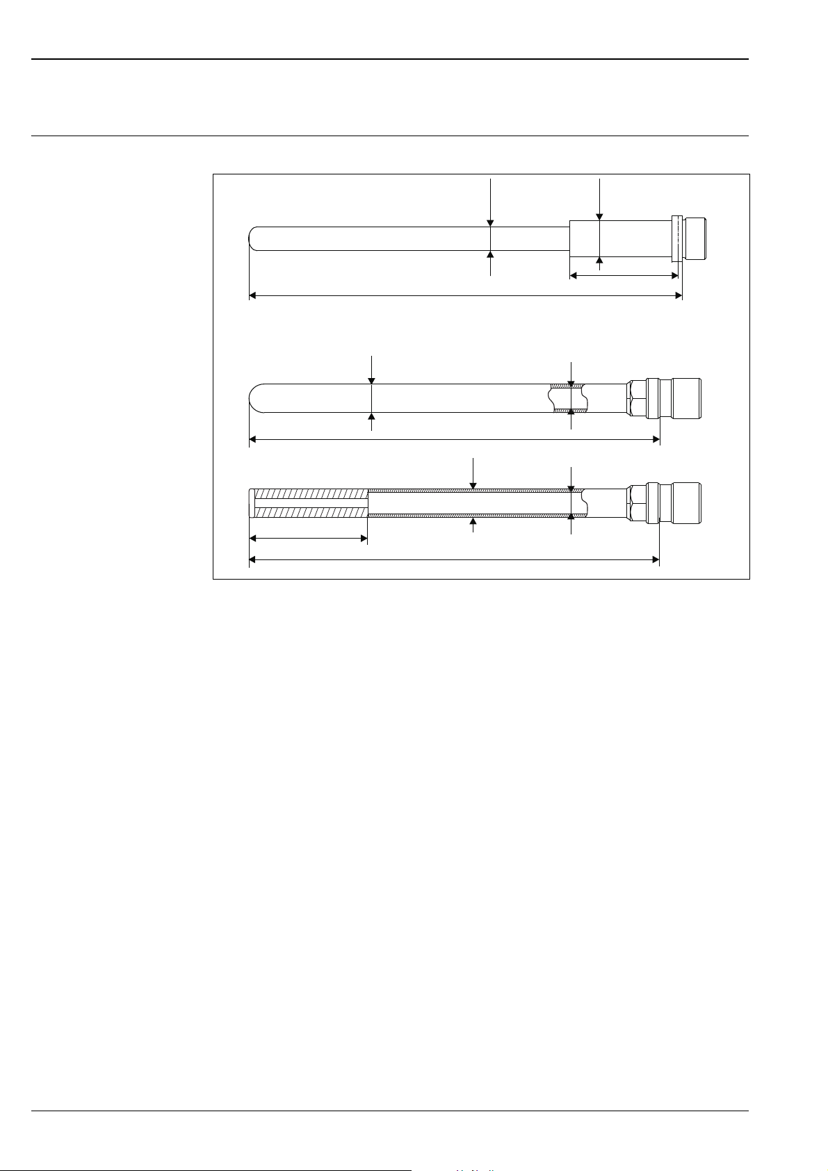
Design, dimensions All dimensions in mm (in).
TWF11, TWF16
TWF11
Sheath diameter
Sleeve length
Sleeve diameter
Length bar stock tip
Immersion length
Thermowell outer diameter
Thermowell inner diameter
CLgTerminal head connection:
M24x1.5 or groove for DIN A head
Immersion length
TWF16
A
Version thermowell made from tube
B
Version thermowell made from tube
and bar stock tip
Terminal head connection:
C
M24x1.5 or groove for DIN A head
Thermowell
• Metallic thermowell, usually machined from tubes or bars.
Ø Lg
Lm
Ø Lm
L2
Lg
ØT
Øi
• Ceramic thermowell.
The selection of the thermowell materials majorly depends on the following material properties, which will
directly influence the lifetime of the sensor:
• Hardness
• Chemical resistance
• Maximum operating temperature
• Wear/abrasion resistance
• Brittleness
• Porosity for process gases
• Creep resistance
Ceramic materials are commonly used for highest temperatures and, due to their hardness, for applications
with high abrasion rates. Attention has to be paid regarding the brittleness of these materials when exposed to
high mechanical loads inside the process. When using porous ceramics as external protection sheath, an
additional, non-porous inner protection sheath has to be used in order to protect the noble sensor elements
from contamination leading to temperature drifts.
4 Endress+Hauser
a0015111
Page 5

TWF11, TWF16
Metal alloys generally show higher mechanical resistance but lower maximum temperature limits and less
abrasion resistance. All metal alloys are non-porous and usually there is no need for an additional inner
protection sheath.
Metal sleeve and process connection
The TWF11 ceramic thermowells are mounted into a metal sleeve which connects them towards the terminal
head. Also the process connection is fitted on the metal sleeve due to its higher mechanical strength. The
dimensions and material type for the sleeve are related to the process temperatures and immersion lengths of
the ceramic thermowells.
All high temperature thermowells are available with an adjustable flange, stop flanges or gas tight compression
fittings.
Weight Depending on length and diameter. Some examples:
• TWF11:
Material SiC or SiN, Ø Lg = 17 mm (0.7 in), Lg = 800 mm (31.5 in), Lm = 300 mm (11.8 in), material
sleeve: AISI 310): 0.8 kg (1.8 lbs)
• TWF16:
Material SiN, Ø A = 26 mm (1.02 in), Lg = 800 mm (31.5 in): 1.4 kg (3.1 lbs)
Material Kanthal AF, Lg = 1000 mm (39.4 in): 0.6 kg (1.3 lbs)
Material NiCo, ¾" schedule 40s, Lg = 1000 mm (39.4 in): 1.9 kg (4.2 lbs)
Process connection
Type
Adjustable flange
Stop flange according to DIN EN 50446
• Max. temperature: +350 °C (+662 °F)
• Material: Aluminum
• Ø depends on sleeve (TWF11) or thermowell pipe (TWF16) diameter
• No gas tight connection
a0015177
• Max. temperature: +400 °C (+752 °F)
• Material: Cast iron
• No gas tight connection
• Counter flange and gasket is not provided
d2 in mm (in) a in mm (in) c in mm (in) clampable sleeve
diameter in mm (in):
23 (0.91) 90 (3.54) 70 (2.76) 21...22 (0.83...0.87) 60000516
33 (1.3) 90 (3.54) 70 (2.76) 31...33 (1.22...1.3) 60000517
Order numbers for reorder as
spare part:
16 (0.63) 75 (2.95) 55 (2.16) 14...15 (0.55...0.59) 60008385
29 (1.14) 90 (3.54) 70 (2.76) 27...28 (1.06...1.1) 71039792
a0015178
Endress+Hauser 5
Page 6

Type
Gas tight GCP assembly
• Max. temperature: +350 °C (+662 °F)
• Material: AISI 316Ti
• Maximum process pressure 1 bar (14.5 psi)
D C in mm (in) Clampable sleeve diameter
in mm (in)
G½" 15.5 (0.61)
17.5 (0.69)
G¾" 15.5 (0.61)
G1" 15.5 (0.61)
a0015179
G1¼" 29 (1.14) 27.5...28 (1.1) 55 71125353
G1½" 22.5 (0.89)
18 (0.71)
19 (0.75)
22.5 (0.89)
18 (0.71)
19 (0.75)
22.5 (0.89)
28 (1.1)
29 (1.14)
35 (1.38)
13.7...14 (0.54...0.55)
17...17.2 (0.67)
13.7...14 (0.54...0.55)
17...17.2 (0.67)
17.5...18 (0.69...0.71)
21.3...22 (0.84...0.86)
13.7...14 (0.54...0.55)
17...17.2 (0.67)
17.5...18 (0.69...0.71)
21.3...22 (0.84...0.86)
26.7...27 (1.05...1.06)
21.3...22 (0.84...0.86)
27.5...28 (1.1)
33.4...34 (1.32...1.34)
SW/Wr. Order numbers for reorder as
36
36
36
36
36
41
41
41
41
41
46
55
55
55
TWF11, TWF16
spare part
60019126
60019129
71031438
60019130
71125362
60020836
60022699
60021758
71125364
60021757
71001827
60021425
71125354
60022497
Installation conditions
Orientation Vertical and horizontal installation. A vertical installation should be preferred due to possible irreversible
bending of metal tubes and the brittleness of the ceramic materials, which could be hit by falling parts.
Installation instructions Recommended maximum immersion length Lg for horizontal mounting:
• 1500 mm (59 in) for diameter > 20 mm (0.8 in)
• 1200 mm (47.3 in) for diameter < 20 mm (0.8 in)
!
Note!
When installing longer lengths than the recommended maximum in horizontal position, the thermowell might
be bend irreversibly under its own weight in the hot environment.
Installation of ceramic sheaths
Thermowells made of ceramic (especially gas tight) are sensitive to fast temperature changes: in order to reduce
the risk of thermal shock and prevent the sheaths from failure, gas tight ceramic sheaths must be heated before
installation. Two possibilities are applicable:
• Installation with pre-heating
When the process is already operating at its running conditions at about 1000 °C (1832 °F) or more, the
ceramic part of the thermowell must be pre-heated from room temperature to 400 °C (752 °F). It is
suggested to use a horizontal, cylindrical cross-section oven or cover the ceramic part with electric heating
elements. Do not use direct flames.
It is suggested to pre-heat the ceramic sheath in situ and then proceed immediately with the insertion. The
measuring system shall be installed carefully with an insertion rate of 100 mm/min, avoiding any mechanical
shock. If it is not possible to run the pre-heating phase near the plant, the insertion rate must be lowered to
30 mm/min because of the cooling of the system during the transportation.
• Installation without pre-heating
If the process is running at its working temperature, the thermowell shall be installed inserting the ceramic
sheath in the plant for a length equal to the wall thickness (including the insulation material) and left in that
position for 2 hours.
After this time, the device shall be installed at a rate of 30 mm/min avoiding any mechanical shock. At
process temperature < 80 °C (176 °F) it is not necessary to consider any insertion rate. It is recommended
to avoid any impact or collision among the ceramic sheath and the components of the plant.
6 Endress+Hauser
Page 7

TWF11, TWF16
Certificates and approvals
CE Mark The device meets the legal requirements of the EC directives if applicable. Endress+Hauser confirms that the
device has been successfully tested by applying the CE mark.
Other standards and
guidelines
DIN EN 50446: Straight thermocouple assembly with metal or ceramic protection tube and accessories,
including terminal heads
PED approval The thermowells comply with paragraph 3.3 of the Pressure Equipment Directive (97/23/CE) and are not
marked separately.
Ordering information
This information provides an overview of the order options available. The information is not exhaustive,
however, and may not be fully up to date. More detailed information is available from your local
Endress+Hauser representative.
Product structure TWF11
Thermowell TWF11 - High temperature, max. 1600 °C (2912 °F)
010 Sheath material; Diameter Lg; max. length Lg, max. temperature:
AA C610; 14 mm; 600 mm; max. Temp. 1500 °C (2732 °F)
AB C610; 14 mm; 1000 mm; max. Temp. 1500 °C (2732 °F)
AC C610; 14 mm; 1500 mm; max. Temp. 1500 °C (2732 °F)
AD C610, 17 mm; 600 mm; max. Temp. 1500 °C (2732 °F)
AE C610; 17 mm; 1000 mm; max. Temp. 1500 °C (2732 °F)
AF C610; 17 mm; 1500 mm; max. Temp. 1500 °C (2732 °F)
AG C610; 24 mm; 600 mm; max. Temp. 1500 °C (2732 °F), internal sheath C610 diameter 17 mm
AH C610; 24 mm; 1000 mm; max. Temp. 1500 °C (2732 °F), internal sheath C610 diameter 17 mm
AJ C610; 24 mm; 1500 mm; max. Temp. 1500 °C (2732 °F), internal sheath C610 diameter 17 mm
BA SiC; 17 mm; 550 mm; max. Temp. 1600 °C (2912 °F)
BB SiC; 17 mm; 850 mm; max. Temp. 1600 °C (2912 °F)
BC SiC; 17 mm; 1150 mm; max. Temp. 1600 °C (2912 °F)
BD SiC; 26.6 mm; 600 mm; max. Temp. 1600 °C (2912 °F)
BE SiC; 26.6 mm; 800 mm; max. Temp. 1600 °C (2912 °F)
BF SiC; 26.6 mm; 1000 mm; max. Temp. 1600 °C (2912 °F)
BG SiC; 26.6 mm; 1200 mm; max. Temp. 1600 °C (2912 °F)
BH SiC; 26.6 mm; 1400 mm; max. Temp. 1600 °C (2912 °F)
BI SiC; 26.6 mm; 1700 mm; max. Temp. 1600 °C (2912 °F)
CA SiN; 16 mm; 600 mm; max. Temp. 1400 °C (2552 °F)
CB SiN; 16 mm; 900 mm; max. Temp. 1400 °C (2552 °F)
CC SiN; 16 mm; 1200 mm; max. Temp. 1400 °C (2552 °F)
CD SiN; 22 mm; 900 mm; max. Temp. 1400 °C (2552 °F)
CE SiN; 22 mm; 1100 mm; max. Temp. 1400 °C (2552 °F)
CF SiN; 22 mm; 1300 mm; max. Temp. 1400 °C (2552 °F)
CG SiN; 22 mm; 1500 mm; max. Temp. 1400 °C (2552 °F)
020 Immersion length Lg:
AA 250 mm
AB 300 mm
AC 400 mm
AD 450 mm
AE 500 mm
AF 550 mm
AG 600 mm
AH 700 mm
AI 750 mm
BA 800 mm
BB 850 mm
BC 900 mm
BD 1000 mm
BE 1050 mm
BF 1100 mm
BG 1150 mm
BH 1200 mm
BI 1300 mm
Endress+Hauser 7
Page 8

020 Immersion length Lg:
CA 1400 mm
CB 1500 mm
CD 1600 mm
CE 1700 mm
X1 ..... mm, as specified (300...600 mm)
X2 ..... mm, as specified (601...1000 mm)
X3 ..... mm, as specified (1001...1500 mm)
030 Sleeve length Lm; Diameter Lm; Material:
B 65 mm; 21.34 mm; AISI 304
F 100 mm; 21.34 mm; AISI 304
G 150 mm; 21.34 mm; AISI 304
H 200 mm; 21.34 mm; AISI 304
J 185 mm; 33.4 mm, AISI 304
K 300 mm; 33.7 mm; AISI 446
L 300 mm; 22 mm; AISI 446
M 400 mm; 33.4 mm; AISI 310
N 400 mm; 22 mm; AISI 310
040 Connection terminal head:
B Thread M24x1.5
F Groove for DIN A head
520 Process connection:
CA Adjustable flange, D=70 mm
CC Stop flange DIN EN 50446, 21...22 mm, clampable, d2=23 mm, a=90 mm, c=70 mm
CE Stop flange DIN EN 50446, 31...33 mm, clampable, d2=33 mm, a=90 mm, c=70 mm
CM GCP assembly, D=G ¾", C=22.5 mm, gas tight, clampable 21.3...22 mm, Wr.=41
CR GCP assembly, D=G 1", C=22.5 mm, gas tight, clampable 21.3...22 mm, Wr.=41
CU GCP assembly, D=G 1½", C=22.5 mm, gas tight, clampable 21.3...22 mm, Wr.=55
CW GCP assembly, D=G 1½", C=35 mm, gas tight, clampable 33.4...34 mm, Wr.=55
895 Marking:
Z1 Tagging (TAG), metal
Z3 Commissioning label, paper
Z6 Tagging (TAG), by customer
TWF11- Order code (complete)
TWF11, TWF16
8 Endress+Hauser
Page 9

TWF11, TWF16
Product structure TWF16
Thermowell TWF16 - High temperature, max. 1700 °C (3092 °F)
010 Material thermowell; maximum temperature:
A AISI 310; 1100 °C (2012 °F)
B AISI 316; 800 °C (1472 °F)
C AISI 446; 1100 °C (2012 °F)
D INCONEL 600; 1100 °C (2012 °F)
E INCONEL 601; 1200 °C (2192 °F)
F INCOLOY 800HT; 1100 °C (2012 °F) (with bar stock tip)
G Kanthal Super; 1700 °C (3092 °F)
H Kanthal AF; 1300 °C (2372 °F)
I Hastelloy X; 1200 °C (2192 °F)
J NiCo; 1200 °C (2192 °F)
K SiN; 1400 °C (2552 °F)
020 Thermowell diameter T:
A1 14 x 11 mm (AISI 310)
A2 17.2 x 14.2 mm (AISI 310)
A3 21.3 x 16.3 mm (AISI 310)
A4 22 x 18 mm (AISI 310)
A5 26.7 x 23.7 mm (AISI 310)
B1 21.3 x 15.76 mm (½" schedule 40, AISI 316)
B2 26.7 x 20.96 mm (¾" schedule 40, AISI316)
C1 21.3 x 15.76 mm (½" schedule 40, AISI 446)
C2 26.7 x 20.96 mm (¾" schedule 40, AISI 446)
D1 15 x 12 mm (INCONEL 600)
D2 17.2 x 13.2 mm (INCONEL 600)
D3 21.3 x 15.76 mm (½" schedule 40, INCONEL 600)
D4 22 x 18 mm (INCONEL 600)
D5 26.7 x 20.96 mm (¾" schedule 40, INCONEL 600)
E1 21.3 x 15.76 mm (½" schedule 40s, INCONEL 601
E2 22 x 18 mm (INCONEL 601)
F1 26.7 x 18.85 mm (¾", schedule 80, INCOLOY 800HT)
G1 18 x 10 mm (Kanthal Super), Lmax = 2000 mm
G2 22 x 13 mm (Kanthal Super) Lmax = 2000 mm
H1 21.3 x 15.76 mm (½" schedule 40, Hastelloy X)
H2 26.7 x 20.96 mm (¾" schedule 40, Hastelloy X)
J1 21.3 x 15.76 mm (½" schedule 40s, NiCo) Lmax = 2000mm
J2 26.7 x 20.96 mm (¾" schedule 40s, NiCo) Lmax = 2000mm
K1 22 x 19.4 mm (Kanthal AF), Lmax = 1000 mm
L1 22 x 12 mm (SiN), Lmax = 1550 mm
L2 28 x 16 mm (SiN), Lmax = 1550 mm
030 Thermowell length (immersion length Lg):
A1 660 mm (SiN)
A2 810 mm (SiN)
A3 960 mm (SiN)
A4 1060 mm (SiN)
A5 1160 mm (SiN)
A6 1260 mm (SiN)
A7 1560 mm (SiN)
X1 ..... mm (200...2000) only for Kanthal Super / NiCo
X2 ..... mm (200...1000) only for Kanthal AF
X3 ..... mm (200...2200)
040 Bar stock tip; Diameter:
0 Not needed
1 INCOLOY 800HT; 26.7 mm
2 NiCo; 21.3 mm
3 NiCo; 26.7 mm
050 Length bar stock tip (L2):
A0 Not needed
A1 300 mm
A2 400 mm
X1 ... mm (200...400)
060 Connection terminal head:
1 Thread M24x1.5
2 Groove for DIN A head
Endress+Hauser 9
Page 10

520 Process connection:
Instruments International
Endress+Hauser
Instruments International AG
Kaegenstrasse 2
4153 Reinach
Switzerland
Tel.+41 61 715 81 00
Fax+41 61 715 25 00
www.endress.com
info@ii.endress.com
CA Adjustable flange diameter 70 mm
CB Stop flange DIN EN 50446, 14...15 mm, clampable, d2=16 mm, a=75 mm,
c=55 mm
CC Stop flange DIN EN 50446, 21...22 mm, clampable, d2=23 mm, a=90 mm,
c=70 mm
CD Stop flange DIN EN 50446, 27...28 mm, clampable, d2=29 mm, a=90 mm,
c=70 mm
CH GCP assembly, D=G ½", C=15.5 mm, gas tight, clampable 13.7...15 mm, Wr.=36
CI GCP assembly, D=G ½", C=17.5 mm, gas tight, clampable 17...17.2 mm, Wr.=36
CJ GCP assembly, D=G ¾", C=15.5 mm, gas tight, clampable 13.7...15 mm, Wr.=36
CK GCP assembly, D=G ¾", C=18 mm, gas tight, clampable 17...17.2 mm, Wr.=36
CL GCP assembly, D=G ¾", C=19 mm, gas tight, clampable 17.5...18 mm, Wr.=36
CM GCP assembly, D=G ¾", C=22.5 mm, gas tight, clampable 21.3...22 mm, Wr.=41
CN GCP assembly, D=G 1", C=15.5 mm, gas tight, clampable 13.7...15 mm, Wr.=41
CP GCP assembly, D=G 1", C=18 mm, gas tight, clampable 17...17.2 mm, Wr.=41
CQ GCP assembly, D=G 1", C=19 mm, gas tight, clampable 17.5...18 mm, Wr.=41
CR GCP assembly, D=G 1", C=22.5 mm, gas tight, clampable 21.3...22 mm, Wr.=41
CS GCP assembly, D=G 1", C=28 mm, gas tight, clampable 26.7...27 mm, Wr.=46
CT GCP assembly, D=G 1 ¼", C=29 mm, gas tight, clampable 27.5...28 mm, Wr.=55
CU GCP assembly, D=G 1½", C=22.5 mm, gas tight, clampable 21.3...22 mm, Wr.=55
CV GCP assembly, D=G 1 ½", C=29 mm, gas tight, clampable 27.5...28 mm, Wr.=55
895 Marking:
Z1 Tagging (TAG), metal
Z3 Commissioning label, paper
Z6 Tagging (TAG), by customer
TWF16- Order code (complete)
TWF11, TWF16
Documentation
High temperature assemblies Omnigrad S TAF11, TAF12x, TAF16 (TI251t/02/en)
TI01015T/09/en/01.11
71131970
FM+SGML 6.0
 Loading...