

Page 1
Products Solutions Services
РЭ 000002R/01/05.16
BA01649T/09/EN/01.16
71369699
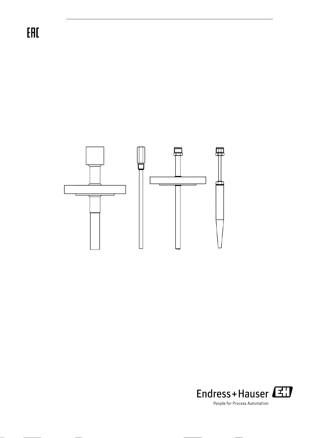
Operating instructions
Thermowells for thermometers
Page 2

__________________________________________________________________________________
2
Page 3

Thermowells for thermometers
__________________________________________________________________________________
Table of contents:
1 Scope and benefits .......................................................................................................................................................... 4
1.1 Scope ....................................................................................................................................................................... 4
1.2 Benefits ................................................................................................................................................................... 4
2 Construction ................................................................................................................................................................... 5
2.1 Genereal information ............................................................................................................................................. 5
2.2 Process temperature range .................................................................................................................................... 7
2.3 Mechanical construction of TA541 ...................................................................................................................... 8
2.4 Mechanical construction of TA414 ...................................................................................................................... 9
2.5 Mechanical construction of TA540 .................................................................................................................... 10
2.6 Mechanical construction of ТА556 .................................................................................................................... 11
2.7 Mechanical construction of ТА560 .................................................................................................................... 12
2.8 Mechanical construction of ТА565 .................................................................................................................... 13
2.9 Mechanical construction of ТА566..................................................................................................................... 14
2.10 Mechanical construction of ТА570, ТА571, ТА572 ....................................................................................... 15
2.11 Mechanical construction of ТА575, ТА576 .................................................................................................... 16
2.12 Mechanical construction of ТА535 .................................................................................................................. 17
2.13 Mechanical construction of ТА550 .................................................................................................................. 18
2.14 Mechanical construction of ТА555 .................................................................................................................. 19
2.15 Mechanical construction of ТА557 .................................................................................................................. 20
2.16 Mechanical construction of ТА562 .................................................................................................................. 21
2.17 Mechanical construction of ТW10 ................................................................................................................... 22
2.18 Mechanical construction of ТW11 ................................................................................................................... 23
2.19 Mechanical construction of ТW12 ................................................................................................................... 24
2.20 Mechanical construction of ТW13 ................................................................................................................... 25
2.21 Mechanical construction of ТW15 ................................................................................................................... 26
2.22 Mechanical construction of ТW45 ................................................................................................................... 27
2.23 Mechanical construction of ТW47 ................................................................................................................... 28
2.24 Mechanical construction of MLTWS01 ............................................................................................................ 29
2.25 Mechanical construction of TW251 ................................................................................................................. 30
2.26 Mechanical construction of TWF11 и TWF16 ................................................................................................ 31
2.27 Mechanical construction of TT411 ................................................................................................................... 32
2.28 Mechanical construction of TT511 ................................................................................................................... 33
2.29 Mechanical construction of TTSP ...................................................................................................................... 34
3 Installation .................................................................................................................................................................... 35
4 Comissioning ................................................................................................................................................................ 36
5 Maintenance and repair .............................................................................................................................................. 36
6 Storage and transport .................................................................................................................................................. 36
7 Conservation ................................................................................................................................................................. 36
8 Assigned indicators ...................................................................................................................................................... 36
9 Limit state criteria ....................................................................................................................................................... 36
10 Occurrence of critical failures ................................................................................................................................... 36
11 Dismantling ................................................................................................................................................................. 36
12 Disposal ....................................................................................................................................................................... 37
13 Marking ...................................................................................................................................................................... 37
14 Manufacturer ............................................................................................................................................................. 37
3
Page 4

Thermowells for thermometers
__________________________________________________________________________________
1 Scope and benefits
1.1 Scope
Thermowells are used for the following purposes:
• To protect thermometers from mechanical and chemical influences of the processes.
• To protect thermometers from unfluences of pressure in pipelines, reactors and tanks.
1.2 Benefits
Thermowells are made from bar stock and from pipe.
Process connection can be threaded, flanged, welded and clamp.
Thermowells are made of different materials that provide corrosion resistance in any of the process.
Possibility of calibration, repair and maintenance of thermometer without stopping of the process.
4
Page 5
Thermowells for thermometers
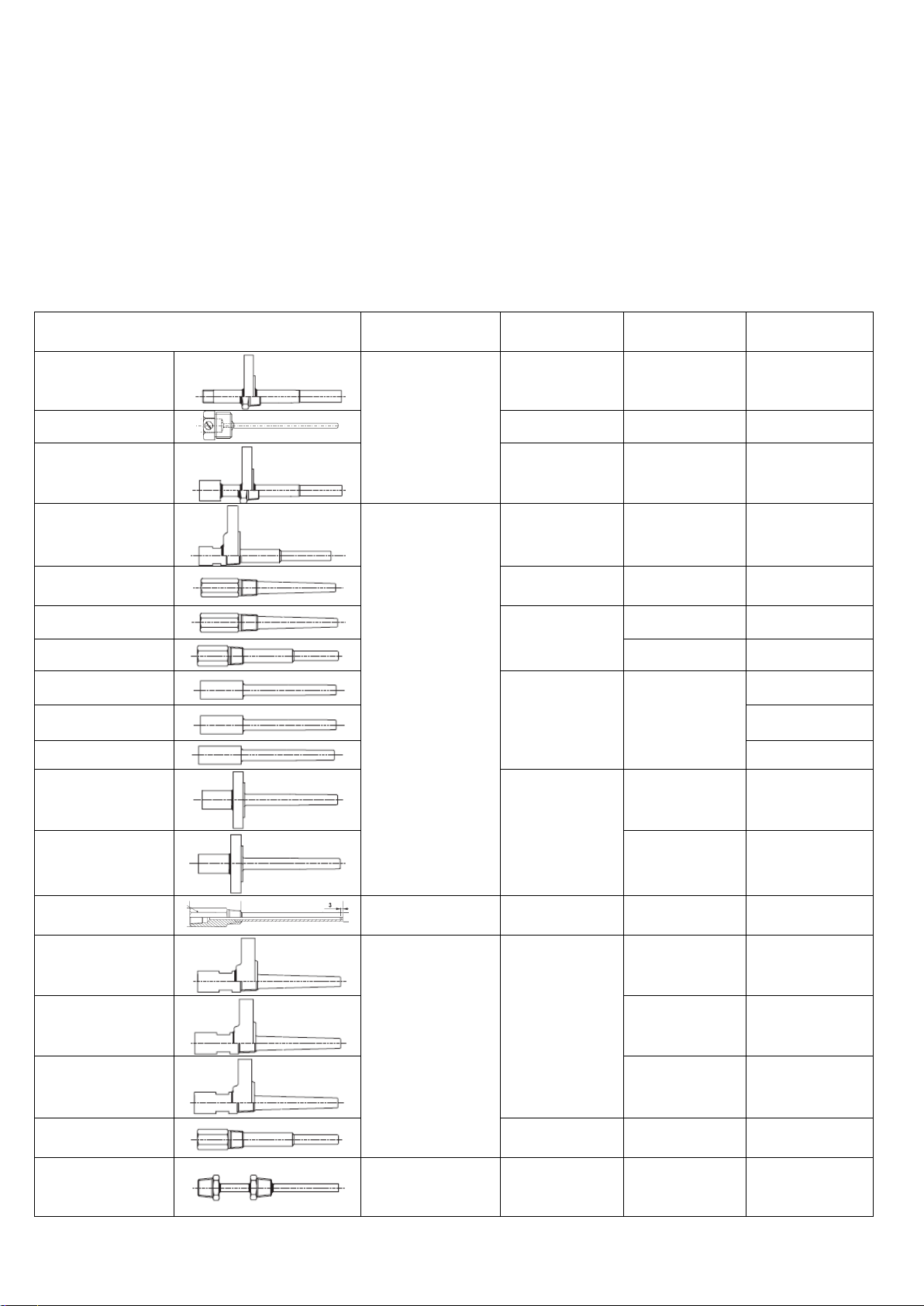
Thermowell model
Type
Material
1
Process
connection
max. process
pressure, MPa2
TA541
Welded extension
pipe
AISI 316, 316L,
A105, 446
Flange DN 25;
50
10
TA414
AISI 316Ti
Thread G1/2”
1
TA540
AISI 316, 316L,
A105, 446
Flange DN 25;
50
10
TA556
Bar stock
AISI 316, 316L
Flange DN 25;
50
30
TA560
AISI 304, 316,
316L, 316Ti
Thread
3/4”NPT
30
TA565
AISI 316, 316L,
316Ti
Thread 1”NPT
30
TA566
Thread 1”NPT
30
TA570
AISI 316, 316L,
316Ti, 321
Socket weld-in
30
TA571
30
TA572
30
TA575
AISI 316, 316L,
316Ti, A105
Flange DN 25;
50
10
TA576
Flange DN 25;
50
30
TA535
Welded extension
pipe
AISI 316L
Threads ½”, ¾”
7,5
TA550
Bar stock
AISI 316, 316L
Flange DN 25;
50
30
TA555
Flange DN 25;
50
30
TA557
Flange DN 25;
50
30
TA562
AISI 316, 316L,
316Ti
Threads ½”, ¾”
30
TW10
Welded extension
pipe
AISI 316L,
316Ti,
Hastelloy C
Threads ½”, ¾”
7,5
__________________________________________________________________________________
2 Construction
2.1 Genereal information
Endress+Hauser offers a complete range of standardized thermowells. Its construction covers a very large
amount of industrial standards as DIN, Dow Chemical, Du Pont, ENI, etc.
Two different types of thermowell construction are available: from drilled bar stock and from pipe.
Herein you can find general information about thermowells.
5
Page 6
Thermowells for thermometers
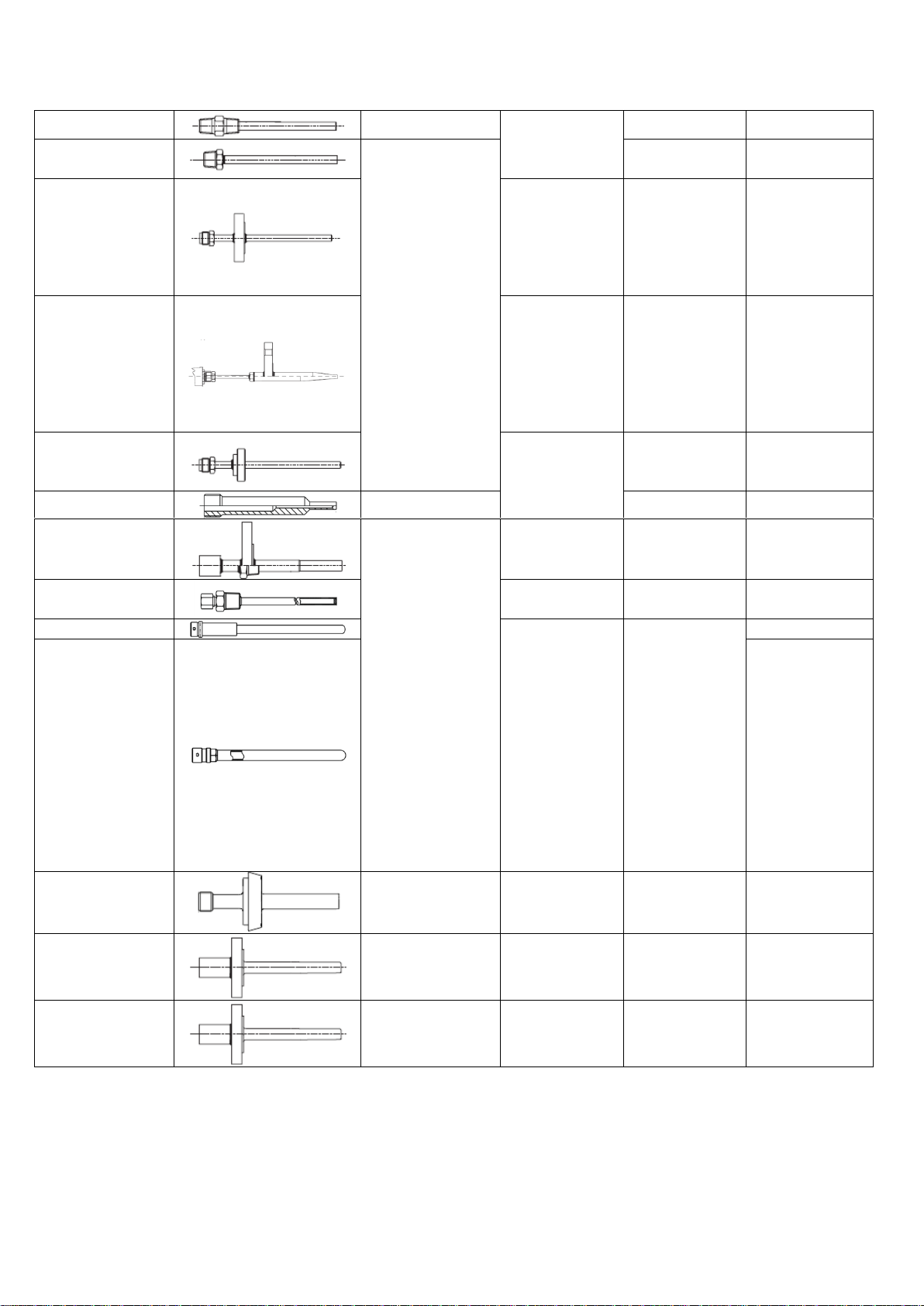
TW11
AISI 316L,
316Ti
Threads ½”, ¾”
7,5
TW12
Welded extension
pipe
Compression
fitting
4
TW13
AISI 316L,
316Ti,
Hastelloy C276,
Inconel 600,
PTFE, PVDF,
Tantalum
Flange DN 25;
50
7,5
TW15
AISI 316Ti,
A182, A105,
Hastelloy C276,
Titanium,
Duplex
SAF2205,
1.5415, 1.7380
Flange DN 25;
50
30
TW45
AISI 316L
Hygienic
adapters up to
2”
4
TW47
Bar stock
Socket weld-in
4
MLTWS01
Welded extension
pipe
AISI 316Ti
Flange DN 25
6,3
TW251
AISI 316L
Socket weld-in,
Threads ¼”, ½”
5
TWF11
AISI 316L, 310,
304, 446,
Inconel 600,
601, Incoloy
800, Hastelloy
X, Kanthal AF,
сплав NiCО,
керамические
материалы:
C610, SiC
сплав, Kanthal
Super, SiN
сплав
Compression
fitting
0,5
TWF16
0,5
TT411
Welded extension
pipe / Bar stock
AISI 316L,
1.4435+316L
Hygienic
adapters up to
2”
0,1
TT511
Bar stock
AISI 316,
A105, 316Ti
Flange DN 25;
50
0,1
TTSP-WT****
Special version,
any construction
Any of
materials
Any of
connections
Any of pressure
__________________________________________________________________________________
1
– depends of ordercode, for special version can be different
2
– depends of ordercode
6
Page 7

Thermowells for thermometers
Thermowell material
Max. process temperature, С
AISI 316
650
AISI 316Ti
700
AISI 316L
650
AISI 321
650
AISI 446
1100
A105 (C22.8)
450
Hastelloy C276
1100
Inconel 600
1100
Tantalum
250
PTFE
200
PVDF
280
Titanium
600
Duplex SAF2205
300
1.5415
530
1.7380
550
AISI 304
850
AISI 310
1100
Inconel 601
1200
Incoloy 800
1100
Hastelloy X
1100
Kanthal AF
1300
NiCo
1200
SiC
1650
Kanthal Super
1700
SiN
1400
C530
1400
C610
1500
C799
1800
__________________________________________________________________________________
2.2 Process temperature range
Process temperature range depends of thermowell material, herein you can find maximum process temperature
ranges:
7
Page 8
Thermowells for thermometers
Position
Description
A
Total length (A=T+L)
L
Immersion length
øQ1
Diameter protection tube tip
R
Length of protection tube tip
T
Extension
D
Bottom thickness
TL1
Thread length for
thread connection
on thermometer
Length in
mm
Thread
20
8
8,5
G½", G¾"
½" NPT
¾" NPT
TL2
Thread length for
thread connection
on process
Length in
mm
Thread
8,5
10
10,5
¾" NPT
1" NPT
1½"NPT
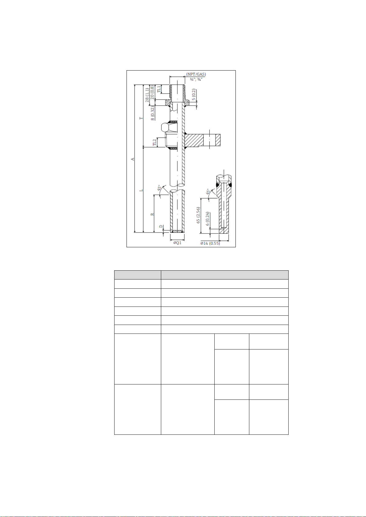
__________________________________________________________________________________
2.3 Mechanical construction of TA541
Pic. 1 – thermowell ТА541 – dimensions in mm (in)
Thermowell ТА541 is made from pipe with bottom thickness 5 mm, outer diameter 13,7mm, 21,34mm or
26,67mm (depends of ordercode), threaded or flanged process connections.
8
Page 9
Thermowells for thermometers
__________________________________________________________________________________
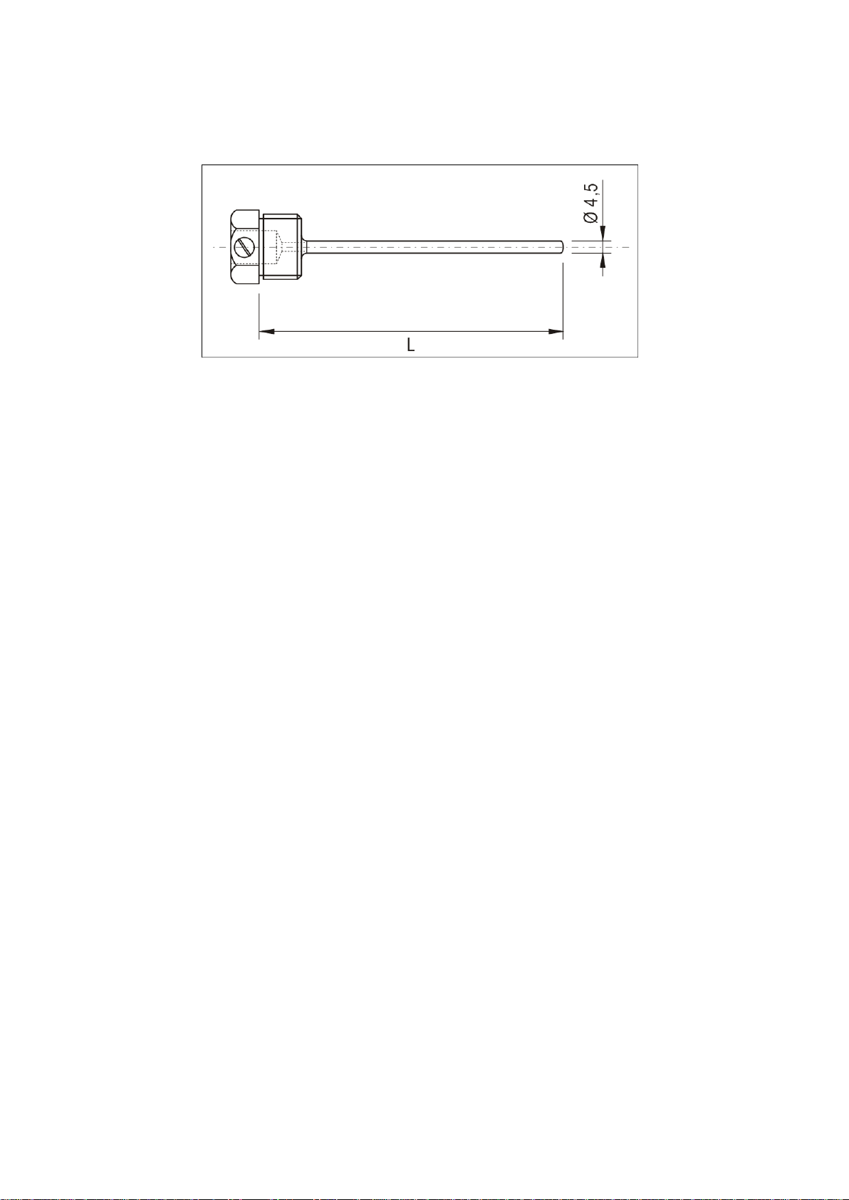
2.4 Mechanical construction of TA414
Pic.2 – thermowell TA414 – dimensions in mm
L – immersion length
Thermowell ТА414 is made from pipe with bottom thickness 3 mm, outer diameter 4,5mm, threaded process
connections, thermowell is used for thermometers with diameter of measuring insert 3 mm.
9
Page 10
Thermowells for thermometers
Position
Description
A
Total length (A=T+L)
L
Immersion length
øQ1
Diameter protection tube tip
R
Length of protection tube tip
T
Extension
__________________________________________________________________________________
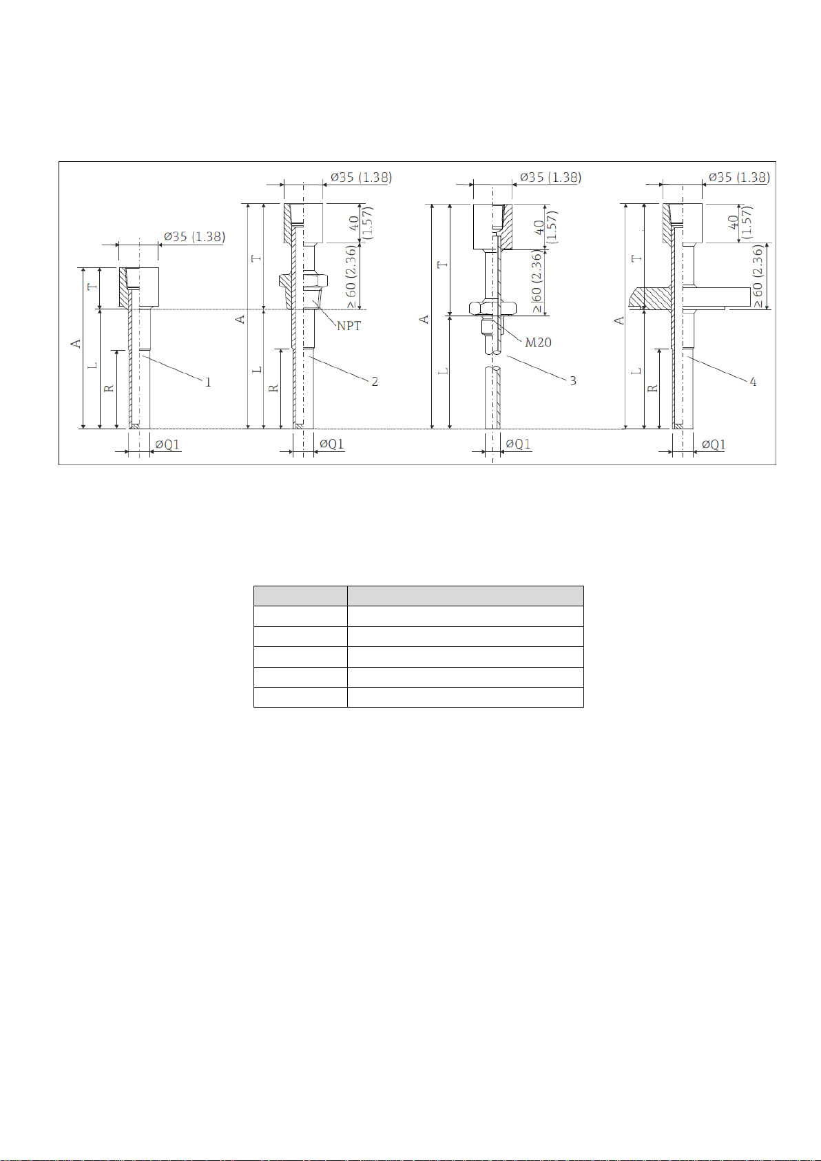
2.5 Mechanical construction of TA540
Pic. 3 – thermowell ТА540 – dimensions in mm (in)
1 without process connection
2 thread NPT
3 thread М20
4 flanged process connection
Thermowell ТА540 is made from pipe with bottom thickness 5 mm, outer diameter 13,7mm, 21,34mm or
26,67mm (depends of ordercode), threaded or flanged process connections.
10
Page 11
Thermowells for thermometers
Position
Description
A
Total length (A=T+U)
U
Immersion length
øQ1
Outer diameter
øQ2
Diameter protection tube tip
R
Length of protection tube tip
T
Extension
øF
Bore diameter
__________________________________________________________________________________
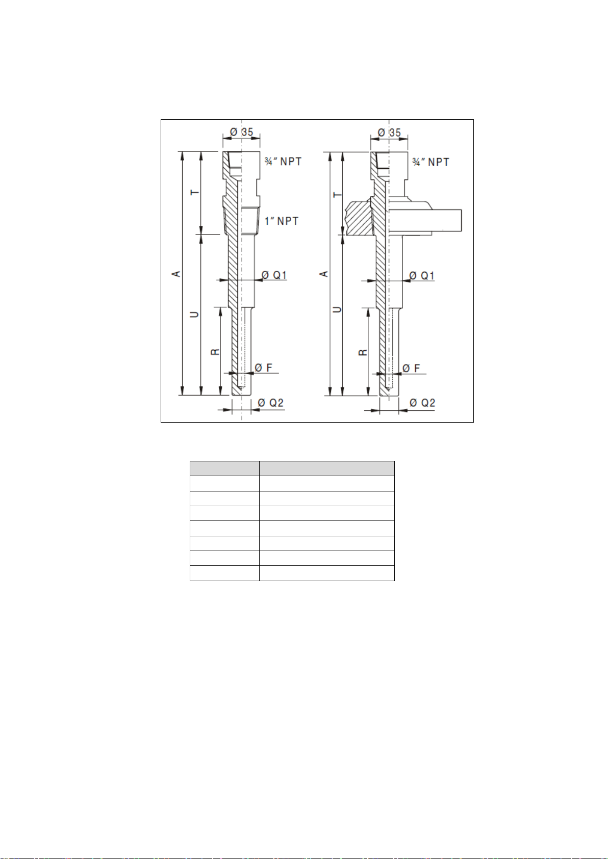
2.6 Mechanical construction of ТА556
Pic. 4 – thermowell ТА556 - dimensions in mm (in)
Thermowell ТА556 is made from round bar stock (drilled) with bore diameter 10 mm or 14mm (special version
for other diameters), cylindrical form with straight or tapered bottom shape, threaded or flanged process
connections.
11
Page 12
Thermowells for thermometers
Position
Description
A
Total length (A=T+U)
U
Immersion length
øQ1
Outer diameter
øQ2
Diameter protection tube tip
T
Extension
øF
Bore diameter
D
Bottom thickness
__________________________________________________________________________________
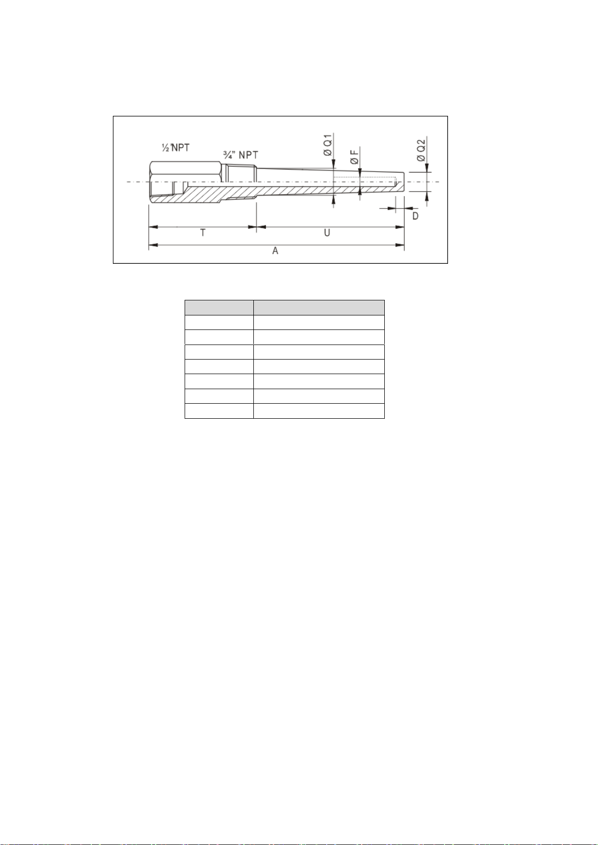
2.7 Mechanical construction of ТА560
Pic. 5 – thermowell ТА560
Thermowell ТА560 is made from round bar stock (drilled) with bore diameter 6.5 mm or 10 mm (special version
for other diameters), cylindrical form with straight or tapered bottom shape, threaded process and thermometer
connections.
12
Page 13

Thermowells for thermometers
Position
Description
A
Total length (A=T+U)
U
Immersion length
øQ1
Outer diameter
øQ2
Diameter protection tube tip
T
Extension
øF
Bore diameter
D
Bottom thickness
__________________________________________________________________________________
2.8 Mechanical construction of ТА565
Pic. 6 – thermowell ТА565
Thermowell ТА565 is made from round bar stock (drilled) with bore diameter 6.5 mm or 10 mm (special version
for other diameters), cylindrical form with straight or tapered bottom shape, threaded process and thermometer
connections.
13
Page 14

Thermowells for thermometers
Position
Description
A
Total length (A=T+U)
U
Immersion length
øQ1
Outer diameter
øQ2
Diameter protection tube tip
T
Extension
øF
Bore diameter
D
Bottom thickness
R
Length of protection tube tip
__________________________________________________________________________________
2.9 Mechanical construction of ТА566
Pic. 7– thermowell ТА566
Thermowell ТА566 is made from round bar stock (drilled) with bore diameter 6.5 mm or 13 mm (special version
for other diameters), cylindrical form with straight or tapered bottom shape, threaded process and thermometer
connections.
14
Page 15

Thermowells for thermometers
Position
Description
ТА570
ТА571
ТА572
U
Immersion length
øQ1
øQ2
Diameter thermowell tip, specification see ordering information
Min. wall thickness 3 mm (0.12 in), (Q2-F1)/2≥3 mm
T
Extension
øF1
Bore diameter
D
Bottom thickness
R
Tapered tip length
S
Thermometer connection thread
øD1
Diameter(extension)
35…49
mm
30…35
mm
25…29 mm
__________________________________________________________________________________
2.10 Mechanical construction of ТА570, ТА571, ТА572
Pic. 8 – thermowells ТА570, ТА571, ТА572
1 Continuous straight shape, flat bottom shape
2 Conical tip shape, flat bottom shape
3 Conical tapered tip shape, flat bottom shape
4 Round bottom shape
Thermowells ТА570, TA571 and TA572 are made from round bar stock (drilled) with bore diameter from 7 mm
and outer diameter up to 27 mm, cylindrical or conical form (depends of ordercode) with welded process
connection.
15
Page 16

Thermowells for thermometers
Position
Description
U
Immersion length
øQ1
Outer diameter
øQ2
Diameter protection tube tip
R
Tapering length, if R = 0 tip shape is straight or
completely conical
T
Extension
øF1
Bore diameter
D
Bottom thickness
S
Connection for thermometer
__________________________________________________________________________________
2.11 Mechanical construction of ТА575, ТА576
Pic. 9 – thermowells ТА575, ТА576
1. Continuous straight shape, flat bottom shape
2. Full penetration welding
3. Standard welding
4. Conical tip shape, flat bottom shape
5. Conical tapered tip shape, flat bottom shape
Thermowells ТА575 and TA576 are made from round bar stock (drilled) with bore diameter from 6,5 mm and
outer diameter up to 27 mm (TA575) and to 28 mm (TA576), cylindrical or conical form (depends of ordercode)
with flanged process connection.
16
Page 17

Thermowells for thermometers
Position
Description
A
Thread
ø
Outer diameter
T
Extension
L
Immersion length
__________________________________________________________________________________
2.12 Mechanical construction of ТА535
Pic. 10 – thermowell ТА535
Pic. 11 – extension – dimensions in mm (in)
1 Process connections: 1/2" NPT or 3/4" NPT
2 Process connections: G½", G3/4" or M20×1,5
Т Extension
Thermowell ТА535 is made from pipe with bottom thickness 3 mm, inner/outer diameter 9/6,5, 10/6,4 or 12/8
mm (depends of ordercode), threaded process and thermometer connections.
17
Page 18

Thermowells for thermometers
Position
Description
A
Total length (A=T+U)
U
Immersion length
øQ1
Outer diameter
øQ2
Diameter protection tube tip
T
Extension
øF
Bore diameter
__________________________________________________________________________________
2.13 Mechanical construction of ТА550
Pic. 12 – thermowell ТА550 – dimensions in mm
Thermowell ТА550 is made from round bar stock (drilled) with bore diameter 7 mm or 8 mm, outer diameter 20
mm and 16 mm (special version for other diameters), threaded or flanged process connections.
18
Page 19

Thermowells for thermometers
Position
Description
A
Total length (A=T+U)
U
Immersion length
øQ1
Outer diameter
øQ2
Diameter protection tube tip
T
Extension
øА1
Bore diameter of protection tube tip
R
Length of protection tube tip
øА2
Bore diameter
__________________________________________________________________________________
2.14 Mechanical construction of ТА555
Pic. 13 – thermowell ТА555 - dimensions in mm
Thermowell ТА555 is made from round bar stock (drilled) with bore diameter 6,5 mm, 7 mm or 8 mm, outer
diameter 24 mm and 14 mm (special version for other diameters), threaded or flanged process connections.
19
Page 20

Thermowells for thermometers
Position
Description
A
Total length (A=T+U)
U
Immersion length
øQ1
Outer diameter
øQ2
Diameter protection tube tip
T
Extension
øF
Bore diameter
__________________________________________________________________________________
2.15 Mechanical construction of ТА557
Pic. 14 – thermowell ТА557 - dimensions in mm
Thermowell ТА557 is made from round bar stock (drilled) with bore diameter 8 mm, outer diameter 25 mm and
14 mm (special version for other diameters), threaded or flanged process connections.
20
Page 21

Thermowells for thermometers
Position
Description
A
Total length (A=T+U)
U
Immersion length
øQ1
Outer diameter
øQ2
Diameter protection tube tip
T
Extension
øF
Bore diameter
D
Bottom thickness
R
Length of protection tube tip
__________________________________________________________________________________
2.16 Mechanical construction of ТА562
Pic. 15– thermowell ТА562 – dimensions in mm
Thermowell ТА562 is made from round bar stock (drilled) with bore diameter 6.5 mm or 10 mm (special version
for other diameters), cylindrical form with straight or tapered bottom shape, threaded process and thermometer
connections.
21
Page 22

Thermowells for thermometers
__________________________________________________________________________________
2.17 Mechanical construction of ТW10
Pic. 16– thermowell ТW10 – dimensions in mm
L – immersion length
E – extension
Thermowell ТW10 is made from pipe with outer diameter 9, 11, 12, 14 or 15 mm, threaded process connections.
22
Page 23

Thermowells for thermometers
__________________________________________________________________________________
2.18 Mechanical construction of ТW11
Pic. 17– thermowell ТW11 – dimensions in mm
L – immersion length
L1 – thread length
Thermowell ТW11 is made from pipe with outer diameter 8, 9, 11, 12, 14 or 15 mm, threaded process
connections.
23
Page 24

Thermowells for thermometers
__________________________________________________________________________________
2.19 Mechanical construction of ТW12
Pic. 18– thermowell ТW12 – dimensions in mm, L – immersion length
Thermowell ТW12 is made from pipe with outer diameter 9, 11, 12, 14 or 15 mm, as process connection is used
compression fitting.
24
Page 25

Thermowells for thermometers
__________________________________________________________________________________
2.20 Mechanical construction of ТW13
Pic. 19– thermowell ТW13 – dimensions in mm
1 M24×1,5 connection; sliding on the neck
2 ½"NPT connection; welded, not sliding on the neck
Е Neck tube length
L Immersion length
øD Diameter
Thermowell ТW13 is made from pipe with outer diameter 9, 11, 12, 14 or 15 mm, flanged process connections.
25
Page 26

Thermowells for thermometers
Position
Description
T
Thread neck tube connection to thermowell
L
Immersion length
U
Length of conical tip
U1
Immersion length; length of the part of the
thermowell in contact with the process from the
tip to the sealing surface of the flange
E
Neck tube length
__________________________________________________________________________________
2.21 Mechanical construction of ТW15
Pic. 20 – thermowell ТW15 – dimensions in mm (in)
Thermowell ТW15 is made from round bar stock (drilled) with outer diameter 24 mm or 18 mm, inner diameter
6,5 mm flanged or welded process connections.
26
Page 27

Thermowells for thermometers
__________________________________________________________________________________
2.22 Mechanical construction of ТW45
Pic. 21 – thermowell ТW45
Е Neck tube length
L Immersion length
øD Pipe diameter
ød Neck tube diameter
Thermowell ТW45 is made from pipe with bottom thickness 3 mm with outer diameter 9 mm: threaded, clamp,
flanged and other hygienic process connections.
27
Page 28

Thermowells for thermometers
__________________________________________________________________________________
2.23 Mechanical construction of ТW47
Pic. 22 – thermowell ТW47– dimensions in mm
TL – total length
L – immersion length
Thermowell ТW47 is made from round bar stock (drilled) with outer diameter 13 mm and 5,3 mm (special
version for other diameters), welded process connections.
28
Page 29

Thermowells for thermometers
__________________________________________________________________________________
2.24 Mechanical construction of MLTWS01
Pic. 23 – thermowell MLTWS01 – dimensions in mm (in)
E– neck length
L – immersion length
Thermowell MLTWS01 is made from pipe with outer diameter 16 mm with flanged process connections.
29
Page 30

Thermowells for thermometers
__________________________________________________________________________________
2.25 Mechanical construction of TW251
Pic. 24 – thermowell TW251 – dimensions in mm
ID – inner diameter
IL – immersion length
Thermowell ТW251 is made from round bar stock (drilled) with diameter 6 mm and 9 mm with threaded or
welded process connections.
30
Page 31

Thermowells for thermometers
Position
Description
Lg
Immersion length
øLg
Sheath diameter
Lm
Sleeve length
øLm
Sleeve diameter
øT
Thermowell outer diameter
øi
Thermowell inner diameter
C
Terminal head connection
A
Version thermowell made from tube
B
Version thermowell made from tube and bar stock tip
L2
Length bar stock tip
__________________________________________________________________________________
2.26 Mechanical construction of TWF11 и TWF16
Pic. 25 – thermowells TWF11 and TWF16
Thermowells ТWF11 and TWF16 are made from metallic or ceramic round bar stock (drilled) with outer
diameter from 14 mm and 26,7 mm (special version for other diameters) for installation in adjustable or stop
flange, or in threaded assembly.
31
Page 32
Thermowells for thermometers
Position
Description
L
Total length (U+T)
U
Immersion length
Т
Length of protection tube shaft
__________________________________________________________________________________
2.27 Mechanical construction of TT411
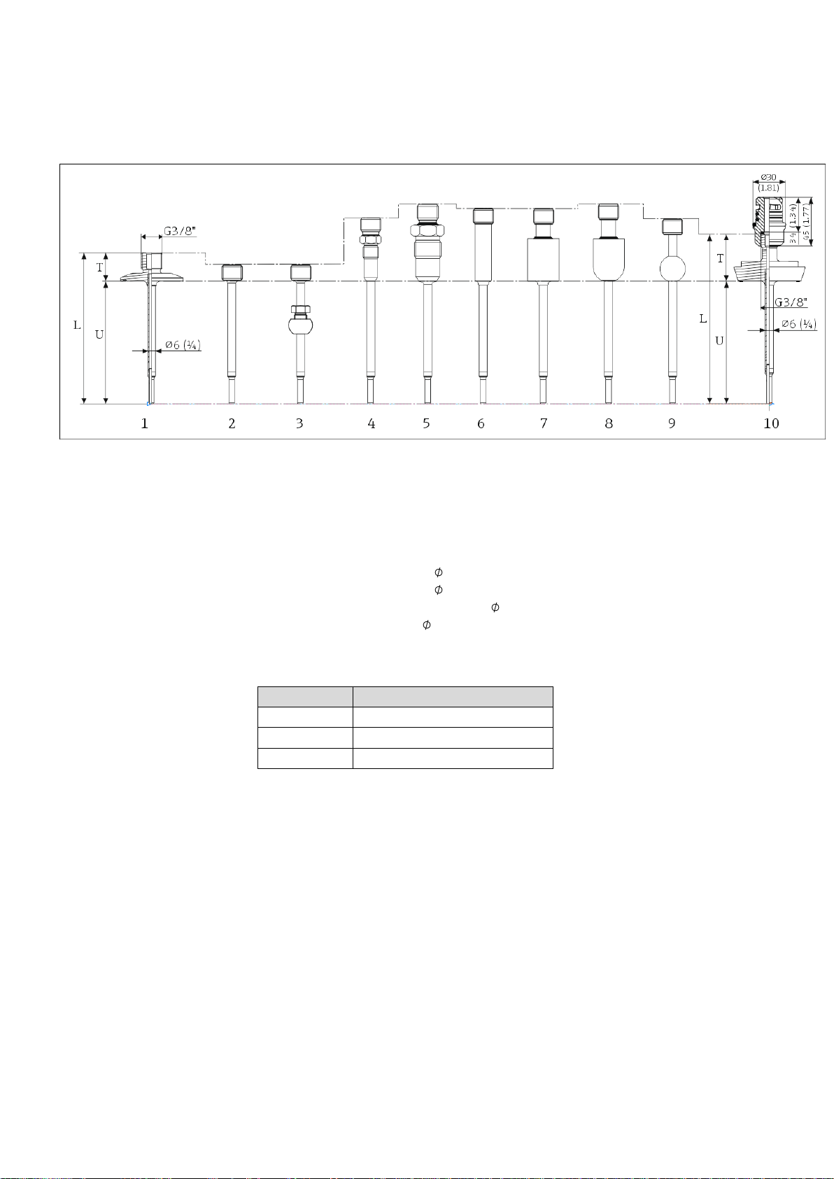
Pic. 26 – thermowell TТ411 – dimensions in mm (in)
1 Clamp version
2 Without process connection
3 Spherical compression fitting TK40
4 Metal sealing system M12x1
5 Metal sealing system G½"
6 Cylindrical weld-in adapter 12 x 40 mm
7 Cylindrical weld-in adapter 30 x 40 mm
8 Spherical-cylindrical weld-in adapter 30 x 40 mm
9 Spherical weld-in adapter 25 mm
10 Sanitary connection according to DIN 11851 with threaded base part
iTHERM QuickNeck
Thermowell TT411 is made from pipe and round bar stock (drilled) with outer diameter from 6 mm to 12,7 mm
(special version for other diameters), hygienic and welded process connections.
32
Page 33

Thermowells for thermometers
Position
Description
L
Standard length
U
Immersion length
LТ
Complete thermowell length (L+U)
TL
Thread length
ML
Insertion length
N
Extension neck length
R
Length of tapered tip
øQ1
Outer diameter
øQ2
Diameter protection tube tip
__________________________________________________________________________________
2.28 Mechanical construction of TT511
Pic. 27 – thermowell TТ511 – dimensions in mm (in)
1 Version DN40 (NPS 1-½") or DN50 (NPS 2"), tapered
2 Version DN40 (NPS 1-½") for L > 300 mm (11.81 in): straight with tapered tip
Thermowell TT511 is made from round bar stock (drilled) with bore diameter 7 mm and outer diameter 19 mm b
30 mm(special version for other diameters), lap joint flange process connections.
33
Page 34

Thermowells for thermometers
__________________________________________________________________________________
2.29 Mechanical construction of TTSP
Pic. 27 – examples of construction of thermowell TTSP – dimensions in mm
TTSP is a special version thermowell made according to customer specification, can be constructed by any
method, with any dimensions and process connections.
34
Page 35

Thermowells for thermometers
__________________________________________________________________________________
3 Installation
Installation of thermowells should be carried out only by qualified and authorized specialists in the
complete absence of pressure at the installation point. Thermowells can be installed on pipes, tanks and
any other parts of the equipment where it is necessary. Seals and gaskets for process connection are
usually not included in the delievery set and customer should provide it separately.
Pic. 28 – thermometer TR62 in connection with thermowell ТА576
35
Pic. 29 – istallation examples in pipes
Page 36

Thermowells for thermometers
Description and cause of accident
Personnel action
Leakage of the working medium (violation
of integrity of the welds between the
submerged part of thermowell and process
connection)
Re-weld the leakage point or replace with a
new thermowell
Leakage of the working medium through
seals (wear of seals the weakening of the
threaded connections)
Tighten threaded connections or replace
gasket
Corrosive or abrasive wear of thermowell
(damage, abrasion, occurrence of holes on
the submersible part due to incorrect choice
of material)
It is necessary to replace it with thermowell
produced of another material, which will
ensure its resistance to mechanical or
corrosive exposure of the working medium.
Assigned storage time
2 years
Assigned lifetime
20 years
__________________________________________________________________________________
4 Comissioning
After mounting of thermowells it is necessary to check tightness of connection on the installation point.
5 Maintenance and repair
Thermowells doesn’t require any special actions for maintenance and repair.
6 Storage and transport
• Transport thermowells to the installation point in original packaging
• Store in a dry and dust-free place
• Storage temperatures: -60…+85°С
7 Conservation
Conservation of thermowells is carried out upon removal from the facility for long term storage. For conservation
it is necessary to eliminate traces of the measured liquid from the surface of the thermowell and remaining oil
from the inside, and then install plugs on it. Conservation of thermowells should be performed according to GOST
9.014-78.
8 Assigned indicators
9 Limit state criteria
The following limit states for operating conditions for thermowells are unacceptable:
• Loss of thermowell tightness
• Occurrence of cracks on the surface of thermowell
10 Occurrence of critical failures
11 Dismantling
In the case if a thermowell reached its limit state, it is necessary to dismantle it, making sure that the system
pressure is shut down.
36
Page 37

Thermowells for thermometers
__________________________________________________________________________________
12 Disposal
The disposal process of thermowells and recycling of materials should be organized so as to prevent pollution of
air, soil and water bodies with harmful substances. Dispose of materials and waste according to the local
regulations.
In general, the safety process for recycling and/or disposal should be provided by:
• Automation and mechanization of technological processes.
• Conduct technological processes in strict compliance with the technical and standard.
• The use of local and general ventilation.
Disposed thermowells do not pose any danger to life, health and the environment. Flowmeters do not contain
any chemical, biological or radioactive elements that could be harmful to human health or the environment.
13 Marking
On thermowell is mentioned its order code, thread type (flange), hole diameter, material of thermowell, lengths
(immersion length, length of conical or truncated tip), the trademark of the manufacturer.
Construction of thermowells doesn't allow to apply on its surface a uniform mark of production circulation at the
market of member States of the Eurasian economic Union, therefore, this sign is applied to technical
documentation package (technical passport, operating instructions).
14 Manufacturer
Endress+Hauser Sicestherm S.r.L., Italy
Address: Via M.Luther King 7, 20060 Pessano con Bornago, Italy
Tel.: +39 02 95 96 41, факс: +39 02 95 96 44 05
e-mail: info@sicestherm.endress.com
37
Page 38

Thermowells for thermometers
__________________________________________________________________________________
38
Page 39

Thermowells for thermometers
__________________________________________________________________________________
39
Page 40

40
 Loading...