

Endress+Hauser Turbimax CUS51D Operating Instructions Manual
Products Solutions Services
BA00461C/07/EN/15.13
71219749
Operating Instructions
Turbimax CUS51D
Sensor for turbidity and solids content

Endress+Hauser
About this document
Notes on safety icons
The structure, signal words and safety colors of the signs comply with the specifications of
ANSI Z535.6 ("Product safety information in product manuals, instructions and other
collateral materials").
Symbols
Safety message structure Meaning
DANGER
!
Cause (/consequences)
Consequences if safety
message is not heeded
‣ Corrective action
This symbol alerts you to a dangerous situation.
Failure to avoid the situation will result in a fatal or serious
injury.
WARNING
!
Cause (/consequences)
Consequences if safety
message is not heeded
‣ Corrective action
This symbol alerts you to a dangerous situation.
Failure to avoid the situation can result in a fatal or serious
injury.
CAUTION
!
Cause (/consequences)
Consequences if safety
message is not heeded
‣ Corrective action
This symbol alerts you to a dangerous situation.
Failure to avoid this situation can result in minor or
medium injury.
NOTICE
Cause/situation
Consequences if safety
message is not heeded
‣ Action/note
This symbol alerts you to situations that can result in
damage to property and equipment.
Additional information, tips
Permitted or recommended
Forbidden or not recommended

Turbimax CUS51D
Endress+Hauser 3
Table of contents
1 Safety instructions . . . . . . . . . . . . . . . . . . 4
1.1 Requirements for the personnel . . . . . . . . . . . . . . . 4
1.2 Designated use . . . . . . . . . . . . . . . . . . . . . . . . . . . . . 4
1.3 Workplace safety . . . . . . . . . . . . . . . . . . . . . . . . . . . 4
1.4 Operational safety . . . . . . . . . . . . . . . . . . . . . . . . . . . 4
1.5 Product safety . . . . . . . . . . . . . . . . . . . . . . . . . . . . . . 5
2 Incoming acceptance and product
identification . . . . . . . . . . . . . . . . . . . . . . 6
2.1 Incoming acceptance . . . . . . . . . . . . . . . . . . . . . . . . 6
2.2 Product identification . . . . . . . . . . . . . . . . . . . . . . . . 6
2.3 Scope of delivery . . . . . . . . . . . . . . . . . . . . . . . . . . . . 6
2.4 Certificates and approvals . . . . . . . . . . . . . . . . . . . . 6
3 Installation . . . . . . . . . . . . . . . . . . . . . . . . 7
3.1 Dimensions . . . . . . . . . . . . . . . . . . . . . . . . . . . . . . . . 7
3.2 Installation instructions . . . . . . . . . . . . . . . . . . . . . . 8
3.3 Installation examples . . . . . . . . . . . . . . . . . . . . . . 10
3.4 Post-installation check . . . . . . . . . . . . . . . . . . . . . 14
4 Wiring . . . . . . . . . . . . . . . . . . . . . . . . . . .15
4.1 Connecting to the transmitter . . . . . . . . . . . . . . . 15
4.2 Post-connection check . . . . . . . . . . . . . . . . . . . . . 15
5 Device description . . . . . . . . . . . . . . . . .16
5.1 Sensor design . . . . . . . . . . . . . . . . . . . . . . . . . . . . . 16
5.2 Measuring principle . . . . . . . . . . . . . . . . . . . . . . . 16
5.3 Measuring methods . . . . . . . . . . . . . . . . . . . . . . . 19
5.4 Application . . . . . . . . . . . . . . . . . . . . . . . . . . . . . . . 21
5.5 Calibration . . . . . . . . . . . . . . . . . . . . . . . . . . . . . . . 23
5.6 Stability criterion . . . . . . . . . . . . . . . . . . . . . . . . . . 29
5.7 Cyclic cleaning . . . . . . . . . . . . . . . . . . . . . . . . . . . . 29
6 Diagnostics and troubleshooting . . . . .30
7 Maintenance . . . . . . . . . . . . . . . . . . . . . .31
7.1 Cleaning the sensor . . . . . . . . . . . . . . . . . . . . . . . 31
8 Repair . . . . . . . . . . . . . . . . . . . . . . . . . . . .32
8.1 Return . . . . . . . . . . . . . . . . . . . . . . . . . . . . . . . . . . . 32
8.2 Disposal . . . . . . . . . . . . . . . . . . . . . . . . . . . . . . . . . 32
9 Accessories . . . . . . . . . . . . . . . . . . . . . . .33
9.1 Assemblies . . . . . . . . . . . . . . . . . . . . . . . . . . . . . . . 33
9.2 Holder . . . . . . . . . . . . . . . . . . . . . . . . . . . . . . . . . . . 33
9.3 Compressed air cleaning . . . . . . . . . . . . . . . . . . . 34
9.4 Transmitter . . . . . . . . . . . . . . . . . . . . . . . . . . . . . . 34
10 Technical Data. . . . . . . . . . . . . . . . . . . . 35
10.1 Input . . . . . . . . . . . . . . . . . . . . . . . . . . . . . . . . . . . . . 35
10.2 Performance characteristics . . . . . . . . . . . . . . . . . 36
10.3 Environment . . . . . . . . . . . . . . . . . . . . . . . . . . . . . . 37
10.4 Process . . . . . . . . . . . . . . . . . . . . . . . . . . . . . . . . . . . 37
10.5 Mechanical construction . . . . . . . . . . . . . . . . . . . . 38
Index . . . . . . . . . . . . . . . . . . . . . . . . . . . . 39

Safety instructions Turbimax CUS51D
4 Endress+Hauser
1 Safety instructions
1.1 Requirements for the personnel
‣
Installation, commissioning, operation and maintenance of the measuring system must
only be carried out by trained technical personnel.
‣ The technical personnel must be authorized by the plant operator to carry out the
specified activities.
‣ The electrical connection may only be performed by an electrical technician.
‣ The technical personnel must have read and understood these Operating Instructions
and must follow the instructions they contain.
‣ Measuring point faults may only be rectified by authorized and specially trained
personnel.
Repairs not described in the enclosed Operating Instructions may only be carried out
directly at the manufacturer's or by the service organization.
1.2 Designated use
CUS51D is a sensor designed to measure the turbidity and solids content of water and
wastewater.
The sensor is particularly suited for use in the following applications:
• Turbidity measurement in the outlet
• Suspended solids in the activated sludge basin and in the recirculation
• Suspended solids in the sludge treatment
• Filterable solids in the outlet
Any other use than the one described here compromises the safety of persons and the entire
measuring system and is not permitted.
The manufacturer is not liable for damage caused by improper or non-designated use.
1.3 Workplace safety
As the user, you are responsible for complying with the following safety conditions:
• Regulations for explosion protection
• Installation instructions
• Local standards and regulations
Electromagnetic compatibility
With regard to electromagnetic compatibility, this device has been tested in accordance with
the applicable European standards for industrial applications.
The electromagnetic compatibility indicated only applies to a device that has been connected
in accordance with the instructions in these Operating Instructions.
1.4 Operational safety
‣
Before commissioning the entire measuring point, make sure all the connections are
correct. Ensure that electrical cables and hose connections are not damaged.
‣ Do not operate damaged products, and safeguard them to ensure that they are not
operated inadvertently. Mark the damaged product as defective.
‣ If faults cannot be rectified, the products must be taken out of service and secured against
unintentional commissioning.

Turbimax CUS51D Safety instructions
Endress+Hauser 5
1.5 Product safety
The product is designed to meet state-of-the-art safety requirements, has been tested and
left the factory in a condition in which it is safe to operate. Relevant regulations and
European standards have been observed.

Incoming acceptance and product identification Turbimax CUS51D
6 Endress+Hauser
2 Incoming acceptance and product
identification
2.1 Incoming acceptance
‣
Make sure the packaging is undamaged!
‣ Inform the supplier about any damage to the packaging.
Keep the damaged packaging until the matter has been settled.
‣ Make sure the contents are undamaged!
‣ Inform the supplier about damage to the contents. Keep the damaged products until the
matter has been settled.
‣ Check that the order is complete and agrees with your shipping documents.
‣ The packaging material used to store or to transport the product must provide shock
protection and humidity protection. The original packaging offers the best protection.
Also, keep to the approved ambient conditions (see "Technical data").
‣ If you have any questions, please contact your supplier or your local sales center.
2.2 Product identification
2.2.1 Nameplate
The nameplate contains the following information:
• Manufacturer data
•Order code
• Extended order code
• Serial number
• Operating conditions
•Safety icons
Compare the order code on the nameplate with your order.
2.2.2 Identifying the product
The order code and serial number of your device can be found in the following locations:
• On the nameplate
• On the front page of these Operating Instructions
• In the delivery papers
To find out the version of your device, enter the order code indicated on the nameplate
in the search screen at the following address:
www.products.endress.com/order-ident
2.3 Scope of delivery
The scope of delivery comprises:
• 1 sensor Turbimax CUS51D in the ordered version
• 1 Operating Instructions BA00461C/07/EN
If you have any questions, please contact your supplier or your local sales center.
2.4 Certificates and approvals
Declaration of conformity
The product meets the requirements of the harmonized European standards. It thus
complies with the legal requirements of the EC directives.
The manufacturer confirms successful testing of the product by affixing the 4 symbol.
Turbimax CUS51D Installation
Endress+Hauser 7
3Installation
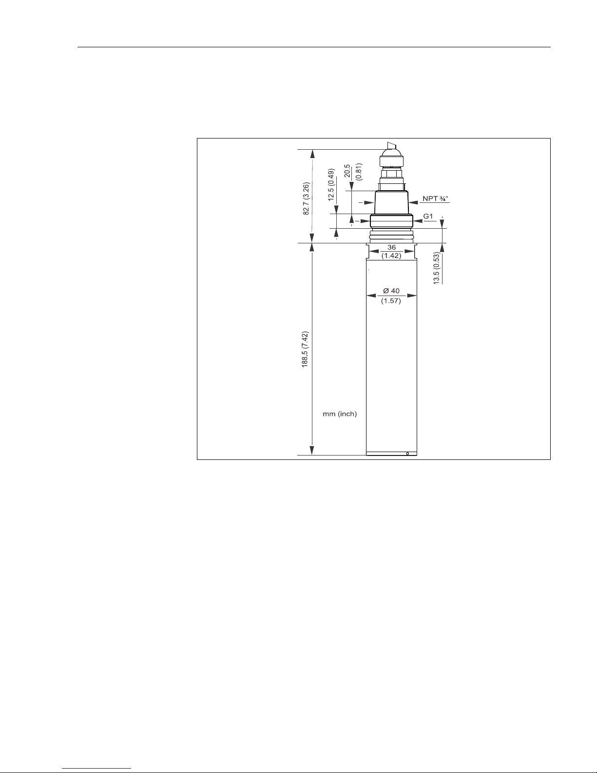
3.1 Dimensions
a0013179
Fig. 1: Dimensions
See the "Accessories" section for the dimensions of the cleaning unit
Installation Turbimax CUS51D
8 Endress+Hauser
3.2 Installation instructions
3.2.1 Measuring system
A complete measuring system comprises:
• Turbidity sensor Turbimax CUS51D
• Transmitter Liquiline
• Assembly:
– Assembly Flexdip CYA112 and holder system Flexdip CYH112 or
– Retractable assembly , e.g. Cleanfit CUA451
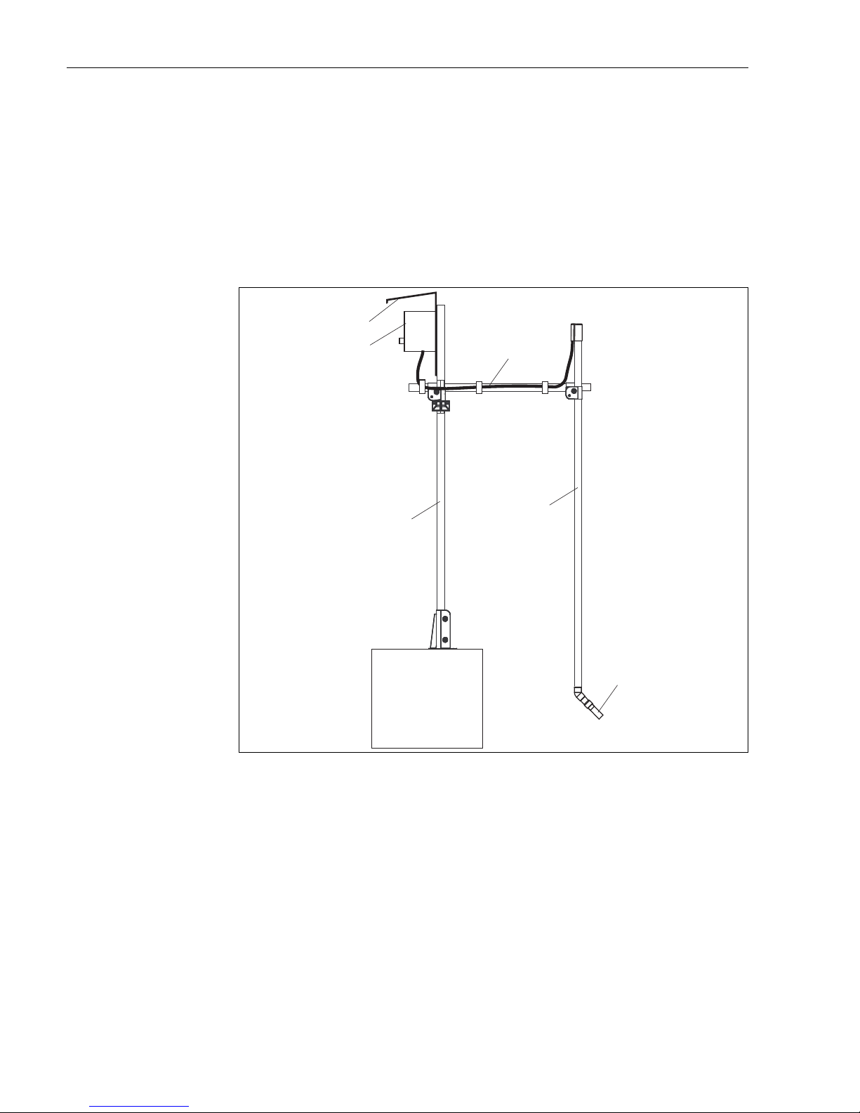
a0012965
Fig. 2: Measuring system with immersion assembly (example)
1
2
3
1
4
5
1 Holder system Flexdip CYH112 4 Assembly Flexdip CYA112
2 Transmitter Liquiline 5 Turbidity sensor Turbimax CUS51D
3 Weather protection roof
Turbimax CUS51D Installation
Endress+Hauser 9
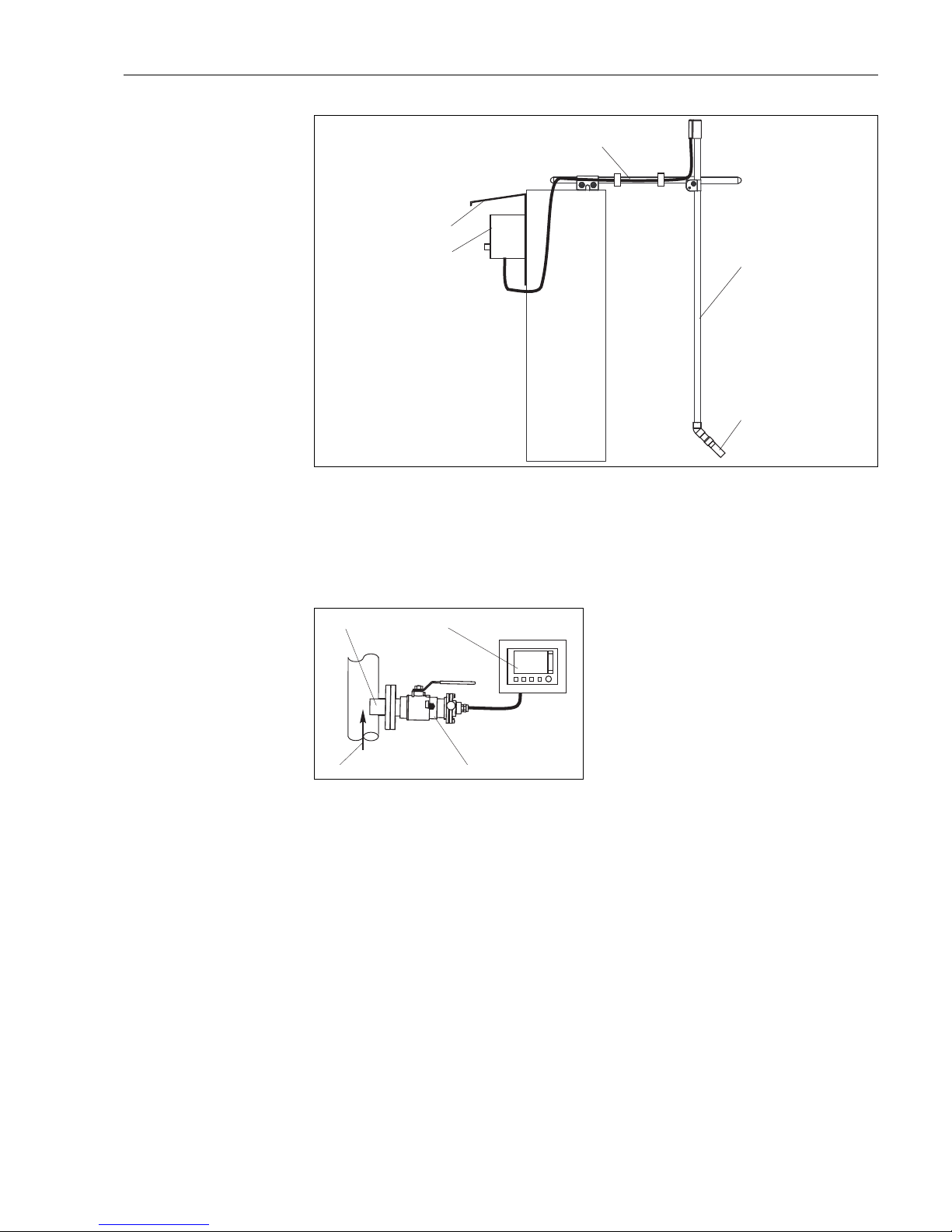
a0013334
Fig. 3: Measuring system with immersion assembly (example)
2
3
5
4
1
1 Transmitter Liquiline 4 Assembly Flexdip CYA112
2 Weather protection roof 5 Turbidity sensor Turbimax CUS51D
3 Holder system Flexdip CYH112
a0012964
Fig. 4: Measuring system with retractable assembly
(example)
1 Turbidity sensor Turbimax CUS51D
2 Transmitter Liquiline
3 Retractable assembly Cleanfit CUA451
4 Flow direction
1
3
4
2
Installation Turbimax CUS51D
10 Endress+Hauser
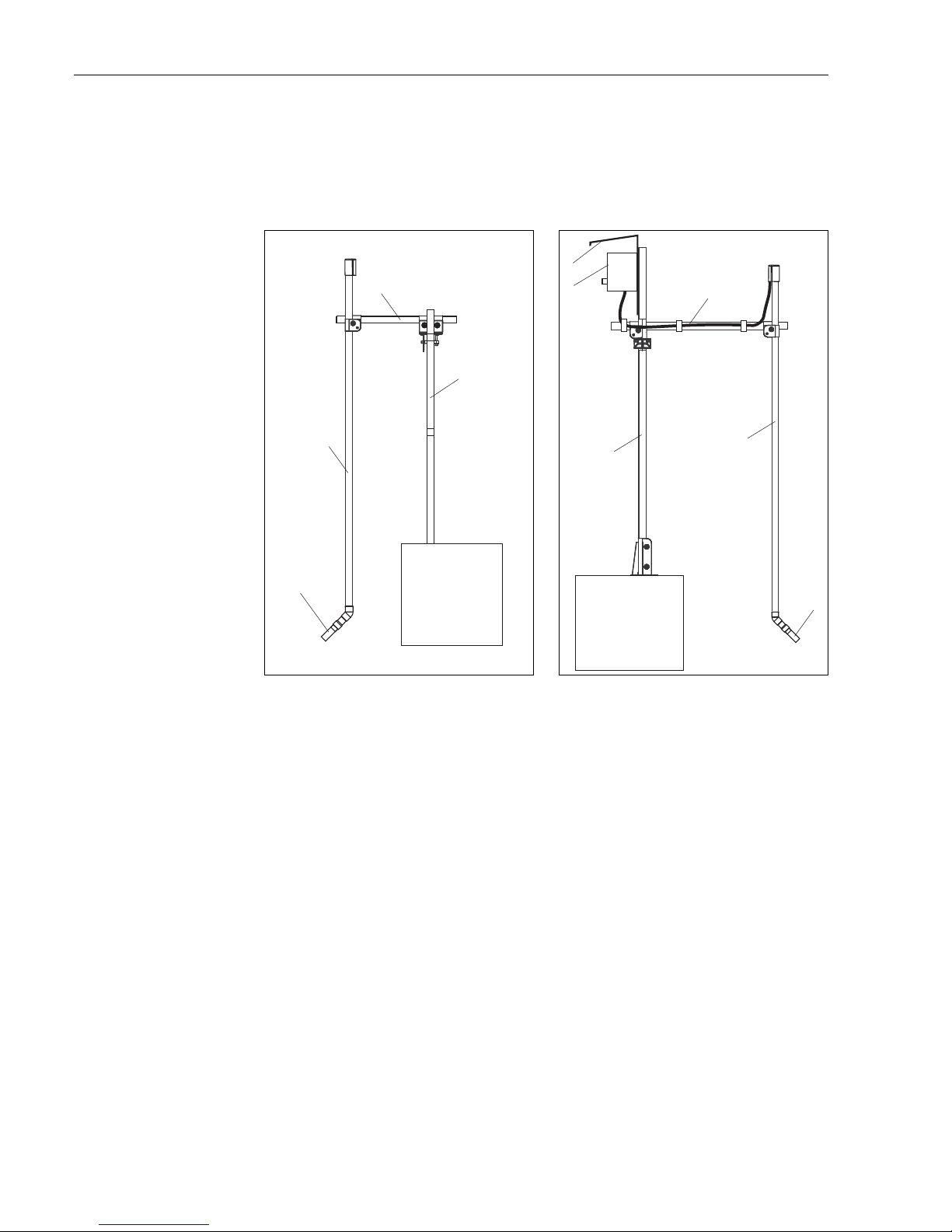
3.3 Installation examples
3.3.1 Immersion operation
Fixed installation with wastewater assembly
This type of installation is particularly suitable for strong or turbulent flow
(>0.5 m/s (1.6 ft/ s)) in the basin or channels.
a0013383
Fig. 5: Installation secured on railing
1 Turbidity sensor Turbimax CUS51D
2 Flexdip CYA112 wastewater assembly
3 Flexdip CYH112 holder
4 Railing
a0012965
Fig. 6: Installation with upright post
1 Flexdip CYH112 holder
2 Multichannel transmitter Liquiline CM44x
3 Weather protection cover
4 Flexdip CYA112 wastewater assembly
5 Turbidity sensor Turbimax CUS51D
1
2
3
4
1
2
3
1
4
5
Turbimax CUS51D Installation
Endress+Hauser 11
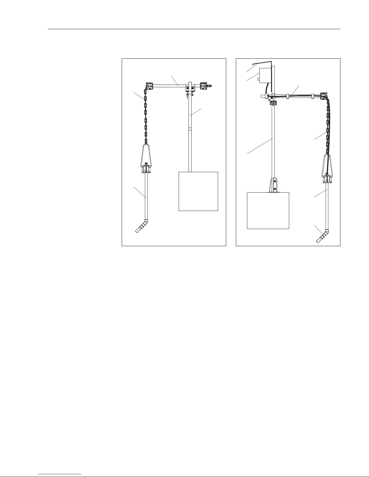
Installation with chain retainer
The chain retainer is particularly suitable for applications that require a sufficient distance
between the mounting location and the edge of the aeration basin. As the assembly is freely
suspended, any vibration of the upright post is practically ruled out.
The swinging movement of the chain retainer enhances the self-cleaning effect of the
optical window.
a0013384
Fig. 7: Chain retainer on railing
1 Flexdip CYA112 wastewater assembly with Turbimax
CUS51D turbidity sensor
2 Chain
3 Flexdip CYH112 holder
4 Railing
a0013386
Fig. 8: Chain retainer on upright post
1 Flexdip CYH112 holder
2 Multichannel transmitter Liquiline CM44x
3 Weather protection cover
4 Flexdip CYA112 wastewater assembly
5 Turbidity sensor Turbimax CUS51D
1
2
3
4
1
2
3
1
4
5
4
Installation Turbimax CUS51D
12 Endress+Hauser
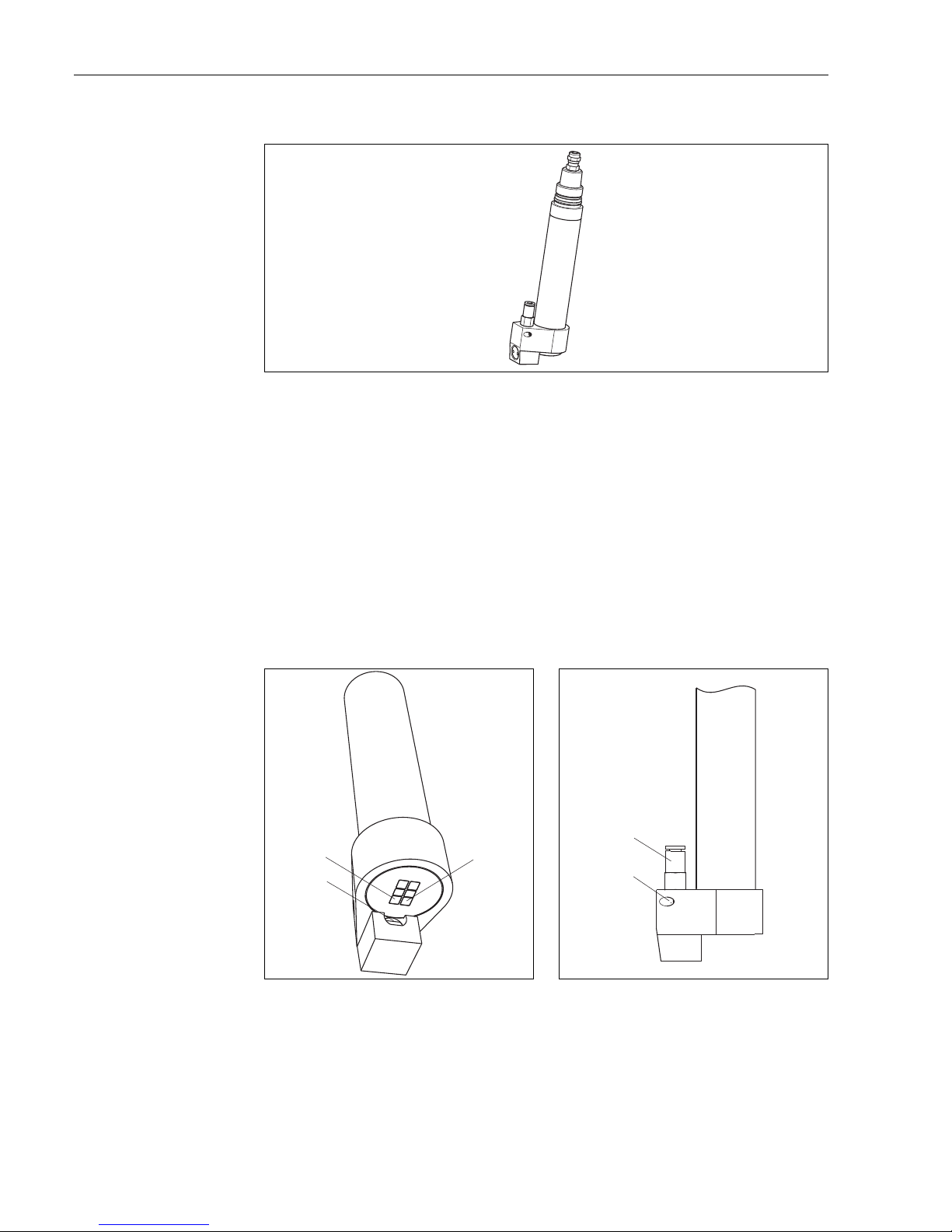
Cleaning unit
a0013259
Fig. 9: Turbimax CUS51D sensor with cleaning unit
The cleaning unit is particularly suitable for clear water and media containing fats/oils that
tend to cause heavy buildup.
Mount the cleaning unit as follows:
1. Fit the cleaning unit onto the sensor as far as it will go.
2. Locate the two LEDs (they are installed at an angle and have a bright enclosure).
3. Position the cleaning unit in such a way that the nozzle is located at the side of the two
LEDs (see å 10).
4. Fix the cleaning unit in place with the securing screw (max. torque: 0.5 Nm
(0.37 lbf ft)).
5. Insert the compressed air hose of the compressor into the hose connection.
a0013410
Fig. 10: Aligning the cleaning unit
1LEDs
2Nozzle
a0013411
Fig. 11: Fixing the cleaning unit
1 Hose connection
2Securing screw
1
2
1
1
2
Turbimax CUS51D Installation
Endress+Hauser 13
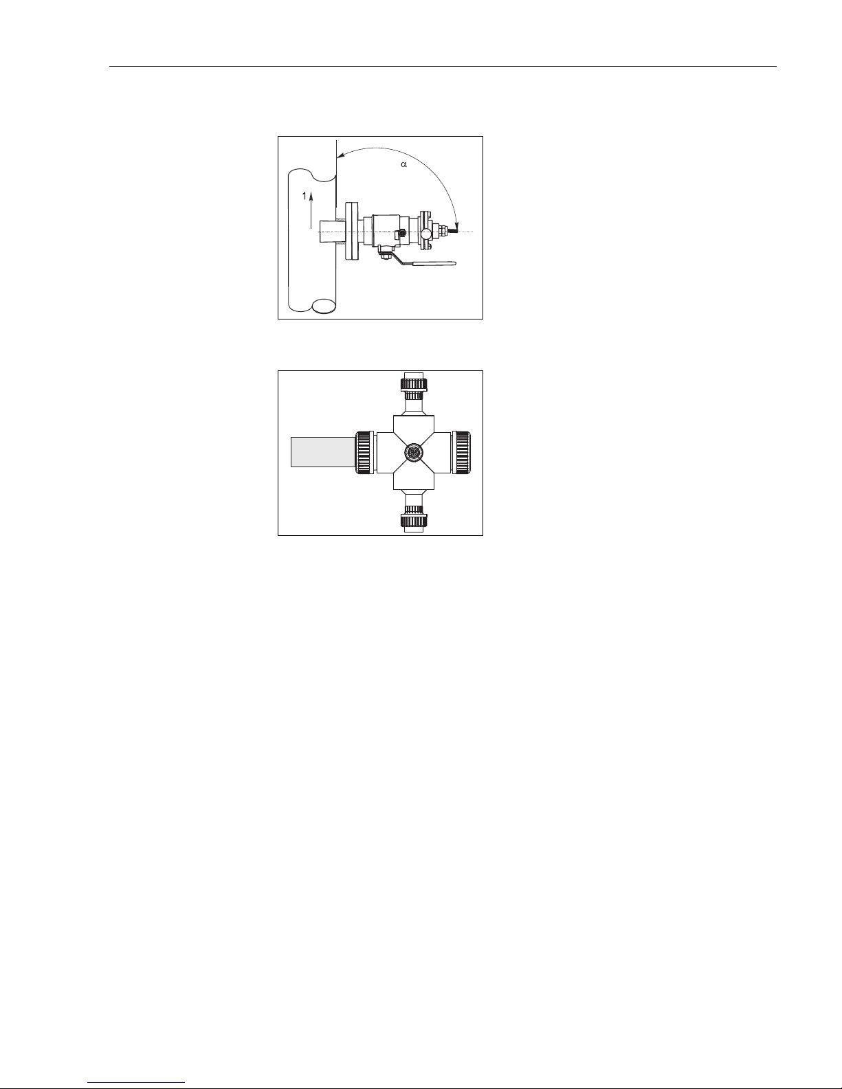
3.3.2 Pipe installation
a0013009
Fig. 12: Installation with retractable assembly
Arrow 1 shows the flow direction.
The installation angle must not exceed 90°.
The recommended installation angle is 75°.
The optical windows of the sensor have to be aligned
parallel to the flow direction ( = 90°) or face the
flow direction ( < 90°).
For manual insertion/retraction of the assembly the
medium pressure may not exceed 2 bar (29 psi).
a0015169
Fig. 13: Installation with flow assembly CYA251
The installation angle is 90°.
Turbidity measurement < 200 FNU will result in
erroneous measuring results due to backscattering of
pipe wall.
 Loading...