

Page 1
TI01135T/09/EN/02.14
71262402
Products Solutions Services
Technical Information
Industrial thermowell
TT511
For Oil & Gas applications
Vanstone type, design with collar flange
Application
The thermowell will be used in applications with high process requirements. The
predominant industries are Oil & Gas and Petrochemical. The process connection
flange ist not welded on the thermowell stem but designed as collar flange. This
special Vanstone thermowell design enables a wide variety of applications and is
suitable for resistance and thermocouple thermometers.
Your benefits
• Solid thermowell, made of drilled barstock material.
• Fulfillment of various, industry specific requirements with a standard product.
Flexible selection of immersion length and thermowell geometry according to the
process specifications.
• In accordance with Shell specification: S.38.113 rev.D and S.38.114 rev.D
• Exact thermowell stress calculation ensuring safe plant operation.
• Vanstone design with outstanding cost effectiveness:
– Reuse of the flange if the thermowell has to be replaced.
– Use of a standard lap joint flange according to ANSI/ASME B16.5 and
EN 1092-1.
– Flexible selection of the flange material, independent from process conditions
and thermowell as it is not in contact with the process medium and it is not
welded on.
– Reduced spare parts and storing concept: one flange can be used for a variety of
thermowells.
Page 2
Function and system design
1
2
3
4
5
6
L
U
Industrial thermowell TT511
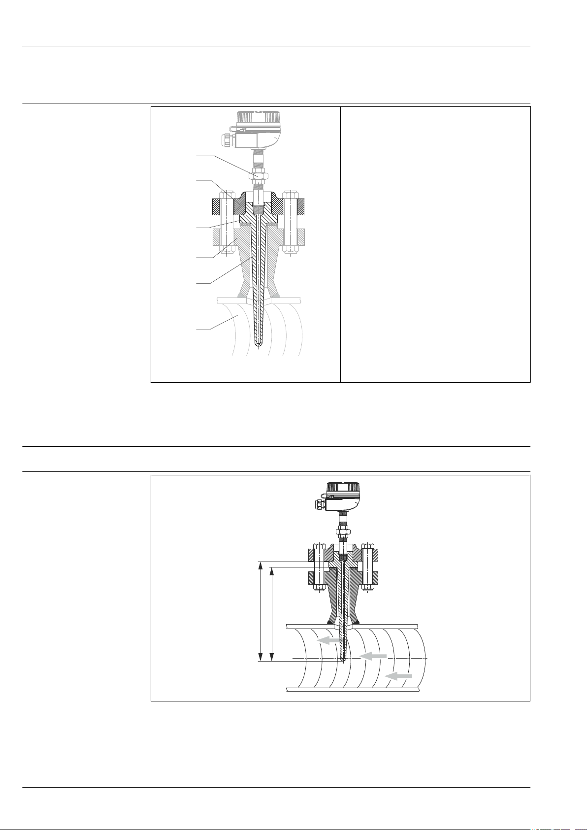
Device architecture
The TT511 Vanstone thermowell is designed as a
special thermowell for thermometer installation (1).
The thermowell shaft (5) and the flange (2) as the
process connection are not interconnected. For
installation in the process (6), the collar (3) of the
thermowell is fitted between two flanges. The flange
(2) on the thermowell side is a slip-on flange that is
fitted onto the thermowell (2) and is bolted to the
connection nozzle (4) on the process side. Many
different flange versions are available to secure the
unit to the permanently installed nozzle flange (4) on
the process side.
The thermowell is machined from solid bar stock.
A0021985
1 TT511 design
Orientation
Installation instructions
Installation
No restrictions.
A0021995
Mounting the TT511
2
The immersion length U of the thermowell can influence the accuracy. If the immersion length is too
small, heat conduction via the process connection and the container wall can cause measurement
errors in the installed thermometer. Therefore, if installing into a pipe the immersion length should
2
Page 3
Industrial thermowell TT511
ideally be half of the pipe diameter. When determining the immersion length or installation depth,
all parameters of the thermowell and the process to be measured must be taken into account (e.g.
flow velocity, process pressure). The counterpieces for the process connections and the seals or
sealing rings are not included in the scope of supply for the thermowell.
Installation possibilities: pipes, tanks or other plant components
Process
Process temperature range
Process pressure (static)
For the maximum operating temperatures, see the 'Material' section. (
Process connection Standard Max. process pressure
Flange EN1092-1 Depending on the flange pressure rating PN:
ASME B16.5 Depending on the flange pressure rating:
Permitted flow velocity depending on the immersion length
The maximum flow velocity tolerated by the thermowell diminishes with increasing thermowell
immersion length exposed to the stream of the fluid. In addition, it depends on the shape and size of
the thermowell, the medium type, process temperature and process pressure.
Thermowell sizing tool
It is possible to check the mechanical loading capacity as a function of the installation and
process conditions online in the TW Sizing Module for thermowells in the Endress+Hauser
Applicator software. See https://wapps.endress.com/applicator
, 63 bar, 100 bar or 160 bar.
40 bar
150 psi, 300 psi, 400 psi, 600 psi, 900 psi, 1500 psi, 2500 psi
→ 7)
3
Page 4
Mechanical construction
5 (0.2)
Q2
!7
(0.28)
1 2
U
L
120 (4.72)
Q1
R3
X
9 (0.35)
14
(0.55)
25 (0.98)
½“ NPT
!24
(0.95)
!B
!A
L
T
Q2
R
Q1
Ra
Ra
Ra
!0.2
A
A
N
TL
ML
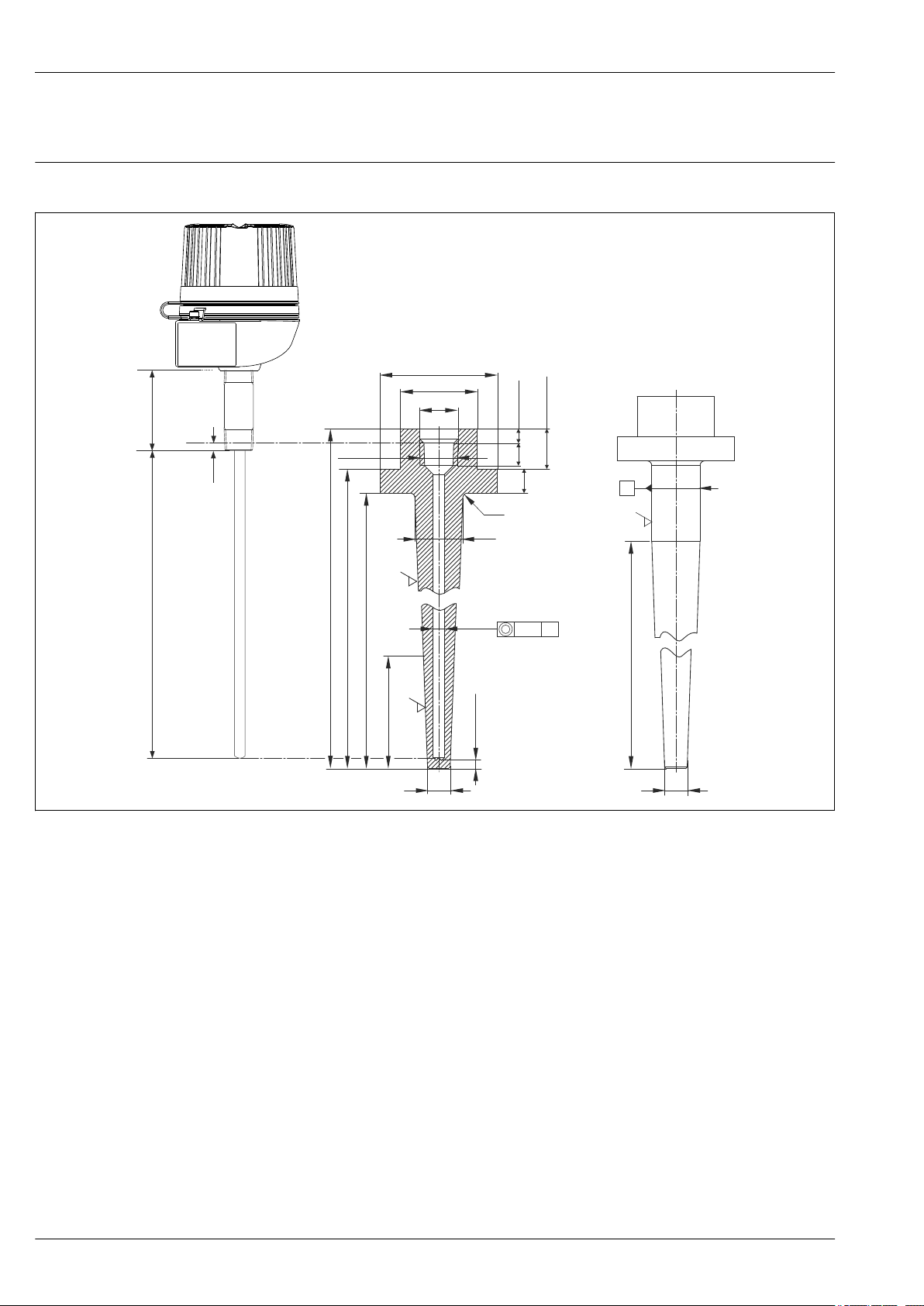
Design, dimensions Vanstone thermowell, type 1
Industrial thermowell TT511
A0022004
All dimensions in mm (in)
3
1 Version DN40 (NPS 1-½") or DN50 (NPS 2"), tapered
2 Version DN40 (NPS 1-½") for L > 300 mm (11.81 in): straight with tapered tip
U Immersion length
R Length of tapered tip
L Standard length
LT Complete thermowell length
ML Insertion length
TL Thread length
N Extension neck length
4
Page 5

Industrial thermowell TT511
The insertion length ML is calculated as follows:
ML = LT - 9 mm
(0.35 in) - 8 mm (0.31 in)
1)
- 5 mm (0.197 in)
Short form: ML = LT - 19 mm (0.75 in)
2)
+ 3 mm (0.12 in)
3)
Version L L
DN40 (NPS 1½") 230 mm
DN50 (NPS 2") 230 mm
in)
(9.1
255 mm
(10.04 in)
305 mm
(12 in)
355 mm
(13.98 in)
405 mm
(15.95 in)
455 mm
(17.91 in)
(9.1 in)
255 mm
(10.04 in)
T
255 mm
(10.04 in)
280 mm
(11.02 in)
330 mm
(13 in)
380 mm
(15 in)
430 mm
(16.93 in)
480 mm
(19 in)
255 mm
(10.04 in)
280 mm
(11.02 in)
U R ExtensionX⌀A ⌀B ⌀Q1 ⌀Q2
215 mm
(8.46 in)
240 mm
(9.45 in)
290 mm
(11.42 in)
340 mm
(13.39 in)
390 mm
(15.35 in)
440 mm
(17.32 in)
210 mm
(8.27 in)
235 mm
(9.25 in)
R = U
240 mm
(9.45 in)
R = U
15 mm
(0.6 in)
20 mm
(0.79 in)
73 mm
(2.87 in)
92 mm
(3.62 in)
48 mm
(1.89 in)
60 mm
(2.36 in)
30 mm
(1.18 in)
30 mm
(1.18 in)
Laser treated specification marking on the lateral surface, e. g. DN50 (nominal diameter),
PN160 (pressure rating), L300 (standard length)-7 (bore diameter), 1.4571 (material), S/N
(serial number), Heat (heat number), TAG
Examples of product configuration
19 mm (³⁄₄ in)
19 mm (³⁄₄ in)
Type 1: DN40 (NPS 1-½")
TT511- A 11 B 12 A 13 B 14
A Nominal diameter, material: DN40 (NPS 1-½"); 316
11 Extension: 15 mm (⁵⁄₈ in) + 25 mm (1 in) DN40 (NPS 1-½")
B Thermometer connection: thread NPT ½"
12 Thermowell geometry: Q1 = 30 mm (¹⁹⁄₁₆ in), Q2 = 19 mm (³⁄₄ in), R = 240 mm (9.45 in)
A Bore diameter: 7 mm (¹⁄₄ in)
13 Bottom thickness; bore shape; tip: D = 5 mm (¹⁄₅ in); standard; flat chamfered
B Surface: Ra ≤ 0.8
14 Standard length: 355 mm (14 in) → selectable according to requirements
Type 1: DN50 (NPS 2")
TT511- B 12 B 11 A 13 A 11
B Nominal diameter, material: DN50 (NPS 2"); 316
12 Extension: 20 mm (³⁄₄ in) + 25 mm (1 in) DN50 (NPS 2")
B Thermometer connection: thread NPT ½"
11 Thermowell geometry: Q1 = 30 mm (¹⁹⁄₁₆ in), Q2 = 19 mm (³⁄₄ in), tapered
1) TL = Thread length
2) Bottom thickness
Distance spring load
3)
5
Page 6

TT511- B 12 B 11 A 13 A 11
R
8 (0.31)
Q2 = !13
(0.51)
!7
(0.28)
R15
(0.6)
L
!50 (1.97)
10 (0.4)
Q1 =
!20 (0.79)
U
5 (0.2)
R1.5
(0.06)
3 (0.12)
30°
!92 (3.62)
1 2
!0.5
A
A
ML
10
(0.4)
A Bore diameter: 7 mm (¹⁄₄ in)
13 Bottom thickness; bore shape; tip: D = 5 mm (¹⁄₅ in); standard; flat chamfered
A Surface: roughened Ra = 6
11 Standard length: 230 mm (9.055 in) → selectable according to requirements
Vanstone thermowell, type 2
Industrial thermowell TT511
4) Bottom thickness
5) Distance spring load
6
All dimensions in mm (in)
4
1 Version DN25, round tip, surface roughness Ra ≤ 1.6
2 Version DN50, round tip, surface roughness Ra ≤ 1.6, full penetration welded collar
U Immersion length
L Standard length in a range from 150 mm (5.9 in) to 500 mm (19.7 in) in 50 mm (1.97 in) increments
R Tapered length 150 mm (5.9 in) or 175 mm (6.9 in), dependent on standard length L
ML Insertion length
The insertion length ML is calculated as follows:
ML = L - 8 mm
(0.31 in)
Short form: ML = L + 5 mm (0.197 in)
4)
+ 10 mm (0.4 in) + 3 mm (0.12 in)
5)
A0021954
Page 7

Industrial thermowell TT511
Examples of product configuration
Type 2: DN25
TT511- C 31 A 31 A 31 C 22
C Nominal diameter, material: DN25; 1.4571
31 Extension: 10 mm (0.4 in)
A Thermometer connection: without
31 Thermowell geometry: Q1 = 20 mm (³⁄₄ in), Q2 = 13 mm (0.51 in), R = 100 mm (3.94 in)
A Bore diameter: 7 mm (¹⁄₄ in)
31 Bottom thickness; bore shape; tip: D = 8 mm (0.32 in); flat; round R15
C Surface: Ra ≤ 1.6
22 Standard length: 200 mm (7.87 in) → selectable according to requirements
Type 2: DN50
TT511- D 32 A 32 A 31 C 26
D Nominal diameter, material: DN50; 1.4571
32 Extension: 10 mm (0.4 in), welded version
A Thermometer connection: without
32 Thermowell geometry: Q1 = 20 mm (³⁄₄ in), Q2 = 13 mm (0.51 in), R = 175 mm (6.9 in)
A Bore diameter: 7 mm (¹⁄₄ in)
31 Bottom thickness; bore shape; tip: D = 8 mm (0.32 in); flat; round R15
C Surface: Ra ≤ 1.6
26 Standard length: 400 mm (15.75 in) → selectable according to requirements
Weight
Material
Laser treated specification marking on the lateral surface, e. g. DN50 (nominal diameter),
PN160 (pressure rating), B300 (standard length)-7 (bore diameter), 1.4571 (material), S/N
(serial number), Heat (heat number), TAG
Variable, according to version and standard length. Some examples:
Version DN40 (NPS 1½") 1.9 kg (4.2 lb) with L = 305 mm (12 in)
Version DN40 (NPS 2") 2.3 kg (5 lb) with L = 230 mm (9.05 in)
Version DN25, round tip 0.6 kg (1.32 lb) with L = 300 mm (11.81 in)
Version DN50, round tip,
full penetration welded
collar
1.1 kg (2.43 lb) with L = 300 mm (11.81 in)
Thermowell and process connections
The temperatures for continuous operation specified in the following table are only intended as
reference values for use of the various materials in air and without any significant compressive load.
7
Page 8

Industrial thermowell TT511
!l
!D
!k
b
h
!J
!m
The maximum operation temperatures are reduced considerably in some cases where abnormal
conditions such as high mechanical load occur or in aggressive media.
Material name Short form Recommended
max. temperature
for continuous use
in air
AISI
316/1.4401
AISI
A105/1.0460
AISI 316Ti/
1.4571
X5CrNiMo 17-12-2 650 °C (1 202 °F) •
C22.8 450 °C (842 °F) • Heat-resistant steel
X6CrNiMoTi17-12-2 700 °C (1 292 °F) • Addition of titanium means increased
Properties
Austenitic, stainless steel
• High corrosion resistance in general
• Particularly high corrosion resistance in
chlorine-based and acidic, non-oxidizing
atmospheres through the addition of
molybdenum (e.g. phosphoric and sulfuric
acids, acetic and tartaric acids with a low
concentration)
• Resistant to atmospheres which contain
nitrogen and are low in oxygen; not suitable
for acids or other aggressive media
• Often used for boilers, water and steam pipes,
pressure vessels
resistance to intergranular corrosion even
after welding
• Broad range of uses in the chemical,
petrochemical and oil industries as well as in
coal chemistry
• Can only be polished to a limited extent,
titanium streaks can form
Process connection
The process connection is provided via the following specified flange connections. The figures shown
below feature the relevant dimensions.
• Standard lap joint flange according to ASME B16.5 for thermowell types DN40 (NPS 1-½") and
DN50 (NPS 2").
• Special design flange (lap joint flange) similar
to DIN EN 1092-1, including safety plug with
chain, length = 150 mm (5.9 in).
5 Dimensions of process connection flange DN40 (NPS 1-½") and DN50 (NPS 2") according to ASME B16.5
Dimensions of process connection flange according to ASME B16.5 in mm (in)
Version Nominal pressure
steps in lb/in²
DN40 (1½") 150 127 (5) 17.5 (0.69) 22.4 (0.88) 98.6 (3.88) 15,7 (0,62) x4
300
900/1500 177.8 (7) 31.8 (1.25) 44.5 (1.75) 124 (4.88) 28.4 (1.12) x4
⌀D b h ⌀k ⌀l ⌀J ⌀m
155.4 (6.12)
20.6 (0.81) 30.2 (1.19)
114.3 (4.5) 22.4 (0.88) x4
A0022167
65 (2,56)
50 (1,97)
69.9 (2.75)400/600 22.4 (0.88) 31.8 (1.25)
8
Page 9

Industrial thermowell TT511
G½“
3.5
(0.14)
2 (0.08)
18
(0.71)
10
(0.4)
!N
!14 (0.55)
C
!w
!x
!L
!K
!D
H
G½“
3.5
(0.14)
18
(0.71)
10
(0.4)
"14
(0.55)
2 (0.08)
"N
C
"L
"K
"D
H
"94 (3.7)
Version Nominal pressure
steps in lb/in²
DN50 (2") 150 152.4 (6) 19.1 (0.75) 25.4 (1) 120.7 (4.75) 19.1 (0.75) x4
300
400/600 25.4 (1) 36.6 (1.44)
900/1500 215.9 (8.5) 38.1 (1.5) 57.2 (2.25) 165.1 (6.5) 25.4 (1) x8 104.6 (4.12)
2500 235 (9.25) 50.8 (2) 69.9 (2.75) 171.5 (6.75) 28.4 (1.12) x8 95.3 (3.75)
⌀D b h ⌀k ⌀l ⌀J ⌀m
165.1 (6.5)
22.4 (0.88) 33.3 (1.31)
127 (5) 19.1 (0.75) x8 84.1 (3.31)
77.7 (3.06)
62.5 (2.46)
6 Dimensions of process connection flange
similar to DIN EN 1092-1, version DN25, PN40 - PN160
Dimensions of process connection flange according to DIN EN 1092-1 in mm (in)
Version ⌀D C H ⌀K ⌀L ⌀N ⌀w ⌀x
DN25/PN40 115 (4.53) 18 (0.71)
DN25/PN100,
PN160
140 (5.51) 24 (0.95) 100 (3.94) 18 (0.71), x4 52 (2.05) 65 (2.56)
30 (1.18)
85 (3.35) 14 (0.55), x4 46 (1.81)
51 (2)
A0022168
68 (2.7)
7 Dimensions of process connection flange
PN100 - PN160 and DN80, PN40
A0022224
similar to DIN EN 1092-1, version DN50, PN40, PN63,
9
Page 10

Industrial thermowell TT511
25 (0.98)
10
(0.4)
G½“
"26
(1.02)
2.5
(0.1)
12 (0.47)
Dimensions of process connection flange according to DIN EN 1092-1 in mm (in)
Version ⌀D C H ⌀K ⌀L ⌀N
DN50/PN40 165 (6.5) 20 (0.79)
DN50, PN63 235 (9.25) 25 (0.98) 180 (7.1) 23 (0.91), x4 90 (3.54)
DN50/PN100,
PN160
DN80, PN40 200 (7.9) 24 (0.94) 160 (6.3) 18 (0.71), x4 105 (4.13)
195 (7.7) - 145 (5.71) 27 (1.06), x4 -
8 Safety plug with chain
30 (1.18)
125 (4.9) 18 (0.71), x4 75 (2.95)
A0022217
PED approval
Material certification
Canadian Registration Number (CRN)
Test on thermowell
Certificates and approvals
The thermowell complies with Art. 3.3 of Pressure Equipment Directive 97/23/EC and is not labeled
separately.
The material certificate 3.1 (according to standard EN 10204) can be selected directly in the order
code. Other material-specific certificates can be requested separately. The "short form" certificate
includes a simplified declaration and has no enclosures of documents related to the materials used,
but guarantees the traceability of the materials through the identification number of the thermowell.
The data related to the origin of the materials can subsequently be requested by the client if
necessary.
CRN-No: OF16064.5
The CRN approval applies for the following thermowell options:
• Nominal diameter DN40 (NPS 1½") for a standard length L up to 455
mm (18 in)
• Nominal diameter DN50 (NPS 2") for a standard length L up to 255 mm (10 in)
More detailed information is available:
• In the download section of the Endress+Hauser website: www.endress.com → Select country →
Download → Enter product root/device → Search area: approvals & certificates → Select certificate
type → Start search
• From your Endress+Hauser Sales Center: www.endress.com/worldwide
Helium leak test as per EN 1779 Leak test for thermowells, welding seams and threaded joints. Depending
on the design and size of the thermowell, it can be subjected to helium gas
internally or externally.
With inspection certificate
Hydrostatic pressure test External and internal pressure test with maximum 400 bar (5 801 psi) to
check the pressure resistance and leak-tightness of thermowells, without
flanges. Internal pressure test only possible for thermowells with an
internal thread (type 1).
With inspection certificate
6)
7)
6) Product configuration, item 10, option A
7) Product configuration, item 10, option B
10
Page 11

Industrial thermowell TT511
Positive material identification
(PMI) test
Load capacity calculation for the
thermowell
Dye penetration test as per ASME
V and EN571-1
Bore concentricity test for
thermowells
Radiographic test as per ASME V,
VIII, TW welding
Nondestructive material identification and testing of welded joints.
Material identification check, X-ray fluorescence analysis
With inspection certificate
In accordance with DIN 43772 or ASME PTC19.3 with calculation
certificate
Suitable for checking welding seam surfaces, e.g. detection of small cracks,
etc.
With inspection certificate
With inspection certificate
With inspection certificate
Ordering information
Detailed ordering information is available from the following sources:
• In the Product Configurator on the Endress+Hauser web site: www.endress.com
country → Products → Select measuring technology, software or components → Select product
(picklists: measurement method, product family etc.) → Device support (right-hand column):
Configure the selected product → The Product Configurator for the selected product is opened.
• From your Endress+Hauser Sales Center: www.addresses.endress.com
Product Configurator - the tool for individual product configuration
• Up-to-the-minute configuration data
Depending on the device: Direct input of measuring point-specific information such as
•
measuring range or operating language
• Automatic verification of exclusion criteria
• Automatic creation of the order code and its breakdown in PDF or Excel output format
• Ability to order directly in the Endress+Hauser Online Shop
→ Choose your
Service-specific accessories
Accessories
Accessories Description
Applicator Software for selecting and sizing Endress+Hauser measuring devices:
• Calculation of all the necessary data for identifying the optimum measuring
device: e.g. pressure loss, accuracy or process connections.
Graphic illustration of the calculation results
•
Administration, documentation and access to all project-related data and
parameters over the entire life cycle of a project.
Applicator is available:
• Via the Internet: https://wapps.endress.com/applicator
• On CD-ROM for local PC installation.
Konfigurator
+temperature
Software for selecting and configuring the product depending on the measuring
task, supported by graphics. Includes a comprehensive knowledge database and
calculation tools:
• For temperature competence
Quick and easy design and sizing of temperature measuring points
•
• Ideal measuring point design and sizing to suit the processes and needs of a wide
range of industries
The Konfigurator is available:
On request from your Endress+Hauser sales office on a CD-ROM for local PC
installation.
11
Page 12

Industrial thermowell TT511
W@M Life cycle management for your plant
W@M supports you with a wide range of software applications over the entire
process: from planning and procurement, to the installation, commissioning and
operation of the measuring devices. All the relevant device information, such as
the device status, spare parts and device-specific documentation, is available for
every device over the entire life cycle.
The application already contains the data of your Endress+Hauser device. Endress
+Hauser also takes care of maintaining and updating the data records.
W@M is available:
• Via the Internet: www.endress.com/lifecyclemanagement
On CD-ROM for local PC installation.
•
FieldCare FDT-based plant asset management tool from Endress+Hauser.
It can configure all smart field units in your system and helps you manage them. By
using the status information, it is also a simple but effective way of checking their
status and condition.
For details, see Operating Instructions BA00027S and BA00059S
www.addresses.endress.com
 Loading...