

Endress+Hauser Topcal S CPC310 Operating Instructions Manual

Operating Instructions
Topcal S CPC310
Automation of pH/Redox Measurements
Field communication via HART® protocol
BA409C/07/en/11.06
71028144
As of software version:
2.60
Brief overview
MEASCAL
DIAGPARAM
15.75
400
320 12.60
227 8.94
16.54
12.87
420
327
250 9.84
300 11.81
max.5/10 m
max.16.4/32.8 ft
max.5 m 16.4ft
max.200 m 656ft
max.2.5 m 8.20ft
C
140107-1000-3A
CPG310
100-110 - 230 VAC
Zusatzventile/
auxiliaryvalves
Jumper
100-230V
/
/
/
/
1
2
1
2
1
2
1
2
r
r
r
r
e
e
til
til
fe
fe
fe
fe
f
f
n
n
f
f
lv
lv
u
u
u
u
a
a
Ve
Ve
P
v
b
v
P
b
100V/
230V
110V
45
46
48 56515752 58
47
200 7.87
24
0.94
13.78
350
B
4142
V1 V2 V3 V4 V9
Power
InterneEingänge/
internalinputs
/
Sicherung/Fuse:
/
/
r
2
M3,15A
r
1
2
e
1
e
r
r
r
r
ig
n
fe
fe
fe
fe
.
.
in
a
f
100-230V
f
f
f
e
u
u
u
.c
.c
u
le
AC
P
b
P
n
n
R
b
c
PE
PEL+PEN- PE
P6
D1P3D2P4P1P5P2
geradeZahlen:minus; ungeradeZahlen:plus;even-numbers: minus; odd-numbers:plus
71027539
Mycom
SPSEingänge/
PCSinputs
/
Programmwahl/
/
ly
r
r
r
b
e
e
tu
m
ig
n
a
e
in
a
s
e
rm
s
le
R
A
a
c
55
V6
/
/
tik
tic
re
n
a
programchoice
a
e
e
5
u
e
/
m
ic
m
8
s
ic
s
1
0
2
v
p
4
v
s
a
p
.
to
r
to
V
r
e
e
S
u
e
u
in
in
.c
in
to
2
e
A
Sto
a
s
R
S
s
b
b
n
b
M
m
1
85 93
B
A
82 9086 9483 918784 9288
81 89
L+ L-
Steuer-Ausgänge/
InterneEingänge/
RückmeldungArmatur/
SPSAusgänge/
driveoutputs
internalinputs
feedbackassembly
PCSoutputs
re
D
/
/
/
u
/
/
/
t-
E
e
f
s
r
/
re
r
n
r
n
e
e
s
e
e
e
r
r
-L
lu
e
u
e
e
u
e
e
lte
h
r
ic
ic
o
k
o
e
s
ic
s
ic
s
s
/
ic
s
r
ic
a
s
c
s
s
v
s
a
s
a
t
p
v
te
rv
rv
rv
itc
h
f
r
liv
rv
n
n
r
e
e
e
e
a
e
ru
e
e
c
u
ir
e
ir
e
e
e
e
w
A
S
s
M
m
D
s
a
s
S
S
s
s
L
a
Wa
w
S
s
M
m
V1V2Ass.
71
12
62 72657566 76
D4 1311 14
61
D3
K1K2
Meas.
V7 V8
S0 S1 S2 S3
3
4
M2
M1
2
1
5
7
6
M3
M4
D
Ausfall
8
HOLD
9
10
11
12
136
1
Messen
2
3
7.54
pH
[¯ ]Wahl
4
5
MEAS CAL
DIAG
PARAM
A
1
2
3
4
7
E
5
F
A
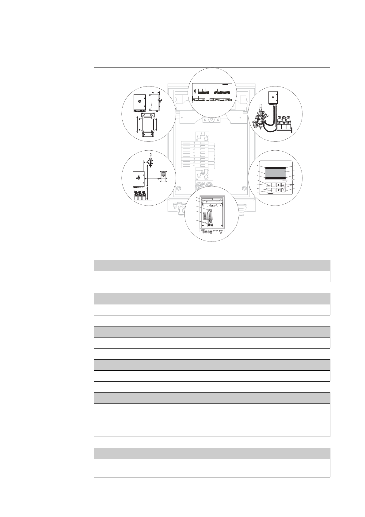
→ ä 11 Installation instructions: Types of mounting, maximum spacing, assembly installation
Æ
B
→ ä 14 Dimensions and installation
Æ
C
→ ä 19 Electrical connection of mandatory and optional system components
Æ
D
→ ä 41 Pneumatic system connection
Æ
E
→ ä 52
→ ä 57
→ ä 106
→ ä 115
Operation
Commissioning
HART commands
Calibration
a0005033
→ ä 135
→ ä 145
Æ
F
Troubleshooting
Spare parts

Table of contents
1 Safety instructions . . . . . . . . . . . . . . . . 5
1.1 Designated use . . . . . . . . . . . . . . . . . . . . . . . . . . . . 5
1.2 Installation, commissioning and operation . . . . . . . . 5
1.3 Operational safety . . . . . . . . . . . . . . . . . . . . . . . . . . 5
1.4 Return . . . . . . . . . . . . . . . . . . . . . . . . . . . . . . . . . . . 6
1.5 Notes on safety conventions and icons . . . . . . . . . . . 6
2 Identification . . . . . . . . . . . . . . . . . . . . 7
2.1 Device designation . . . . . . . . . . . . . . . . . . . . . . . . . 7
2.1.1 Nameplate . . . . . . . . . . . . . . . . . . . . . . . . . 7
2.1.2 Scope of delivery . . . . . . . . . . . . . . . . . . . . . 7
2.1.3 Product structure . . . . . . . . . . . . . . . . . . . . 8
2.2 Certificates and approvals . . . . . . . . . . . . . . . . . . . . 9
3 Installation . . . . . . . . . . . . . . . . . . . . . 10
3.1 System setup . . . . . . . . . . . . . . . . . . . . . . . . . . . . . 10
3.2 Incoming acceptance, transport, storage . . . . . . . . . 11
3.3 Installation conditions . . . . . . . . . . . . . . . . . . . . . . 11
3.3.1 Types of mounting . . . . . . . . . . . . . . . . . . . 11
3.3.2 Spacing . . . . . . . . . . . . . . . . . . . . . . . . . . . 12
3.3.3 Assembly installation . . . . . . . . . . . . . . . . . 12
3.3.4 Dimensions . . . . . . . . . . . . . . . . . . . . . . . . 13
3.4 Installation instructions . . . . . . . . . . . . . . . . . . . . . 14
3.4.1 Securing rinsing block to assembly . . . . . . . 14
3.4.2 Installation instructions . . . . . . . . . . . . . . . 14
3.4.3 Wall mounting . . . . . . . . . . . . . . . . . . . . . 15
3.4.4 Post mounting and panel mounting . . . . . . 16
3.5 Post-installation check . . . . . . . . . . . . . . . . . . . . . . 18
4 Wiring . . . . . . . . . . . . . . . . . . . . . . . . 19
4.1 Electrical connection . . . . . . . . . . . . . . . . . . . . . . . 19
4.1.1 Overview . . . . . . . . . . . . . . . . . . . . . . . . . 19
4.1.2 Connection compartment sticker for
CPG310 control unit . . . . . . . . . . . . . . . . . 21
4.1.3 Connection compartment sticker,
Mycom S CPM153 . . . . . . . . . . . . . . . . . . 22
4.1.4 Power supply and communication connection
between transmitter and control unit . . . . . 23
4.1.5 Level probes for buffer and cleaner . . . . . . 24
4.1.6 Analog sensors . . . . . . . . . . . . . . . . . . . . . 25
4.1.7 Digital sensors with
Memosens technology . . . . . . . . . . . . . . . . 30
4.1.8 Current outputs . . . . . . . . . . . . . . . . . . . . . 32
4.1.9 Mycom relays . . . . . . . . . . . . . . . . . . . . . . 35
4.1.10 External inputs (PLC to CPG310 ) and
outputs (CPG310 to PLC) . . . . . . . . . . . . . 36
4.1.11 External inputs (PLC to Mycom) . . . . . . . . 37
4.1.12 Inductive limit position switch . . . . . . . . . . 38
4.2 Post-connection check . . . . . . . . . . . . . . . . . . . . . . 40
5 Medium connection. . . . . . . . . . . . . . . 41
5.1 Compressed air pipe and additional valves . . . . . . . 41
5.2 Water pipe and rinse chamber . . . . . . . . . . . . . . . . 42
5.3 Multihoses . . . . . . . . . . . . . . . . . . . . . . . . . . . . . . . 43
5.3.1 Connecting multihoses . . . . . . . . . . . . . . . 44
5.4 Assemblies . . . . . . . . . . . . . . . . . . . . . . . . . . . . . . . 45
5.4.1 Cleanfit CPA471/472/475 . . . . . . . . . . . . 45
5.4.2 Cleanfit CPA473/474 . . . . . . . . . . . . . . . . 47
5.5 Pumps . . . . . . . . . . . . . . . . . . . . . . . . . . . . . . . . . . 49
5.5.1 Compressed air control . . . . . . . . . . . . . . . 49
5.5.2 Buffer and cleaner . . . . . . . . . . . . . . . . . . . 50
5.5.3 Venting . . . . . . . . . . . . . . . . . . . . . . . . . . . 51
5.6 Post-connection check . . . . . . . . . . . . . . . . . . . . . . 51
6 Operation . . . . . . . . . . . . . . . . . . . . . . 52
6.1 Display and operating elements . . . . . . . . . . . . . . . 52
6.1.1 Display . . . . . . . . . . . . . . . . . . . . . . . . . . . 52
6.1.2 Function of keys . . . . . . . . . . . . . . . . . . . . 52
6.1.3 Service switch . . . . . . . . . . . . . . . . . . . . . . 53
6.1.4 Measured value display . . . . . . . . . . . . . . . 54
6.1.5 Operation access authorization . . . . . . . . . . 54
6.1.6 Menu editor types . . . . . . . . . . . . . . . . . . . 55
6.2 Operation via FieldCare . . . . . . . . . . . . . . . . . . . . . 56
7 Commissioning . . . . . . . . . . . . . . . . . . 57
7.1 Points to note when commissioning
digital sensors . . . . . . . . . . . . . . . . . . . . . . . . . . . . 57
7.2 Points to note when commissioning
ISFET sensors . . . . . . . . . . . . . . . . . . . . . . . . . . . . 57
7.3 Function check . . . . . . . . . . . . . . . . . . . . . . . . . . . 57
7.4 Switching on . . . . . . . . . . . . . . . . . . . . . . . . . . . . 58
7.5 Quick Setup . . . . . . . . . . . . . . . . . . . . . . . . . . . . . . 58
7.5.1 Configuring Clean program . . . . . . . . . . . . 61
7.6 Device configuration . . . . . . . . . . . . . . . . . . . . . . . 63
7.6.1 Set up 1 - Sensor input . . . . . . . . . . . . . . . . 63
7.6.2 Set up 1 - Display . . . . . . . . . . . . . . . . . . . 64
7.6.3 Set up 1 - Access codes . . . . . . . . . . . . . . . 64
7.6.4 Set up 1 - Current outputs . . . . . . . . . . . . . 65
7.6.5 Set up 1 - Relays . . . . . . . . . . . . . . . . . . . . 67
7.6.6 Set up 1 - Temperature . . . . . . . . . . . . . . . 68
7.6.7 Set up 1 - Alarm . . . . . . . . . . . . . . . . . . . . 70
7.6.8 Set up 1 - Hold . . . . . . . . . . . . . . . . . . . . . 71
7.6.9 Set up 1 - Calibration . . . . . . . . . . . . . . . . . 73
7.6.10 Set up 1 - Topcal validation function . . . . . 78
7.6.11 Set up 2 - Data log . . . . . . . . . . . . . . . . . . . 79
7.6.12 Set up 2 - Check . . . . . . . . . . . . . . . . . . . . 80
7.6.13 Set up 2 - Controller configuration . . . . . . . 82
7.6.14 Set up 2 - Limit switch . . . . . . . . . . . . . . . . 88
7.6.15 Set up 2 - Controller quick adjustment . . . . 90
7.6.16 Set up 2 - Topcal . . . . . . . . . . . . . . . . . . . 90
7.6.17 Set up 2 - Chemoclean . . . . . . . . . . . . . . 100
7.6.18 Manual operation . . . . . . . . . . . . . . . . . . 104
3

7.7 HART commands . . . . . . . . . . . . . . . . . . . . . . . . 106
7.7.1 Universal commands . . . . . . . . . . . . . . . . 106
7.7.2 Common practice commands . . . . . . . . . . 107
7.7.3 Device-specific commands . . . . . . . . . . . . 108
7.8 Diagnosis . . . . . . . . . . . . . . . . . . . . . . . . . . . . . . . 109
7.9 Calibration . . . . . . . . . . . . . . . . . . . . . . . . . . . . . 115
7.9.1 Calibration pH . . . . . . . . . . . . . . . . . . . . . 116
7.9.2 Calibration redox . . . . . . . . . . . . . . . . . . . 118
11 Technical data . . . . . . . . . . . . . . . . . . 154
11.1 Input . . . . . . . . . . . . . . . . . . . . . . . . . . . . . . . . . 154
11.2 Output . . . . . . . . . . . . . . . . . . . . . . . . . . . . . . . . 154
11.3 Power supply . . . . . . . . . . . . . . . . . . . . . . . . . . . 155
11.4 Performance characteristics . . . . . . . . . . . . . . . . . 155
11.5 Environment . . . . . . . . . . . . . . . . . . . . . . . . . . . 156
11.6 Process . . . . . . . . . . . . . . . . . . . . . . . . . . . . . . . . 156
11.7 Mechanical construction . . . . . . . . . . . . . . . . . . . 156
8 Maintenance . . . . . . . . . . . . . . . . . . . 122
8.1 Maintenance of the overall measuring point . . . . . 122
8.1.1 Cleaning the transmitter . . . . . . . . . . . . . 122
8.1.2 Cleaning the sensors . . . . . . . . . . . . . . . . 122
8.1.3 Maintenance of digital sensors . . . . . . . . . 124
8.1.4 Liquid KCl supply . . . . . . . . . . . . . . . . . . 124
8.1.5 Manual calibration . . . . . . . . . . . . . . . . . . 124
8.1.6 Assembly . . . . . . . . . . . . . . . . . . . . . . . . . 125
8.1.7 Cables, connections and
power supply lines . . . . . . . . . . . . . . . . . . 125
8.1.8 Control unit . . . . . . . . . . . . . . . . . . . . . . 126
9 Accessories . . . . . . . . . . . . . . . . . . . . 127
9.1 Sensors . . . . . . . . . . . . . . . . . . . . . . . . . . . . . . . . 127
9.2 Connection accessories . . . . . . . . . . . . . . . . . . . . 127
9.3 Mounting accessories . . . . . . . . . . . . . . . . . . . . . . 128
9.4 Assemblies . . . . . . . . . . . . . . . . . . . . . . . . . . . . . 129
9.5 Offline configuration . . . . . . . . . . . . . . . . . . . . . . 130
9.6 Communication . . . . . . . . . . . . . . . . . . . . . . . . . . 130
9.7 Housing CYC310 . . . . . . . . . . . . . . . . . . . . . . . . 131
9.7.1 Product structure . . . . . . . . . . . . . . . . . . . 132
9.8 Operating panel for CPC310 . . . . . . . . . . . . . . . . 133
12 Appendix . . . . . . . . . . . . . . . . . . . . . . 157
12.1 Operating matrix . . . . . . . . . . . . . . . . . . . . . . . . 157
12.2 Wiring example for external program start . . . . . . 170
12.3 Buffer tables . . . . . . . . . . . . . . . . . . . . . . . . . . . . 171
Index . . . . . . . . . . . . . . . . . . . . . . . . .172
10 Troubleshooting . . . . . . . . . . . . . . . . 135
10.1 Troubleshooting instructions . . . . . . . . . . . . . . . . 135
10.2 System error messages . . . . . . . . . . . . . . . . . . . . . 136
10.3 Process-specific errors . . . . . . . . . . . . . . . . . . . . . 140
10.4 Device-specific errors . . . . . . . . . . . . . . . . . . . . . . 143
10.5 Response of outputs to errors . . . . . . . . . . . . . . . . 144
10.5.1 Current output behavior . . . . . . . . . . . . . 144
10.5.2 Response of contacts to errors . . . . . . . . . 144
10.5.3 Response of contacts to power failure . . . . 145
10.5.4 Assembly behavior . . . . . . . . . . . . . . . . . . 145
10.6 Spare parts . . . . . . . . . . . . . . . . . . . . . . . . . . . . . 145
10.6.1 Device view Mycom S . . . . . . . . . . . . . . . 146
10.6.2 Spare parts list Mycom S . . . . . . . . . . . . . 146
10.6.3 Control unit device view . . . . . . . . . . . . . 147
10.6.4 Control unit spare parts list . . . . . . . . . . . 147
10.6.5 View of canister with membrane pump
and level sensor . . . . . . . . . . . . . . . . . . . . 148
10.6.6 Spare parts list for canister with membrane
pump and level sensor . . . . . . . . . . . . . . . 149
10.6.7 Pneumatic and hydraulic control unit . . . . 150
10.6.8 Rinsing block . . . . . . . . . . . . . . . . . . . . . . 151
10.7 Replacing the device fuse . . . . . . . . . . . . . . . . . . . 152
10.8 Return . . . . . . . . . . . . . . . . . . . . . . . . . . . . . . . . . 153
10.9 Disposal . . . . . . . . . . . . . . . . . . . . . . . . . . . . . . . 153
4

Safety instructions
1 Safety instructions
1.1 Designated use
Topcal S CPC310 is a fully automated measuring, cleaning and calibration system for pH and redox
measurement.
The system is fully equipped with power supply cables and hose systems.
Topcal S CPC310 can be operated using the handheld terminal DXR375 or at a PC by means of the
FieldCare program via a HART
The system is particularly suitable for use in the following areas:
• Chemical process systems
• Pharmaceuticals
• Foodstuff industry
• Water treatment and monitoring
• Wastewater treatment
• Sewage treatment plants
• Chemical pulp and paper industry
Topcal S CPC310 is suitable for use in hazardous atmospheres.
Any use other than that described here compromises the safety of persons and the entire measuring
system and is, therefore, not permitted.
The manufacturer accepts no liability for damage resulting from incorrect use or use other than that
designated.
®
modem, e.g. Commubox FXA191.
1.2 Installation, commissioning and operation
Note the following points:
• Installation, commissioning, operation and maintenance of the measuring system must be carried
out exclusively by specially trained technical personnel.
The personnel must be authorized to perform such work by the system operator.
• The electrical connection may only be established by an electrical technician.
• Technical personnel must have read and understood these Operating Instructions and must
adhere to them.
• Before commissioning the entire measuring point, check all the connections for correctness.
Ensure that electrical cables and hose connections are not damaged.
• Do not commission damaged products. Protect them against inadvertent commissioning. Mark
the damaged product as defective.
• Faults at the measuring point may only be rectified by authorized and specially trained personnel.
• If faults cannot be rectified, you must take the products out of operation and protect them against
inadvertent commissioning.
• Repairs not described in these Operating Instructions may only be carried out directly at the
manufacturer's or by the service organization.
1.3 Operational safety
The system is designed to meet state-of-the-art safety requirements, has been tested and left the
factory in a condition in which it is safe to operate. The applicable regulations and European
standards have been taken into consideration.
As the user, you are responsible for ensuring the following safety regulations are observed:
• Installation regulations
• Local standards and regulations
5

Safety instructions
#
Electromagnetic compatibility
With regard to electromagnetic compatibility, this device has been tested in accordance with the
applicable European standards for industry.
The electromagnetic compatibility indicated only applies to a device that is connected in accordance
with the instructions in these Operating Instructions.
1.4 Return
If the device has to be repaired, please return it cleaned to your sales center.
For returns please use the original packaging.
1.5 Notes on safety conventions and icons
Warnings
Warning!
This symbol alerts you to hazards which could cause serious injuries, as well as damage to the
instrument, if ignored.
"
!
%
&
(
)
*
b
Caution!
This symbol alerts you to possible faults which could arise from incorrect operation. They could
cause damage to the instrument if ignored.
Note!
This symbol indicates important items of information.
Electrical symbols
Direct current
A terminal at which DC voltage is applied or through which DC flows.
Alternating current
A terminal at which (sine-form) alternating voltage is applied or through which AC flows.
Direct or alternating current
A terminal at which direct or alternating voltage is applied or through which AC flows.
Ground connection
A terminal which, from the user's point of view, is already grounded using a grounding system.
Protective earth terminal
A terminal which must be grounded before other connections may be established.
Alarm relay
Input
Output
DC voltage source
Temperature sensor
6
2 Identification
2.1 Device designation
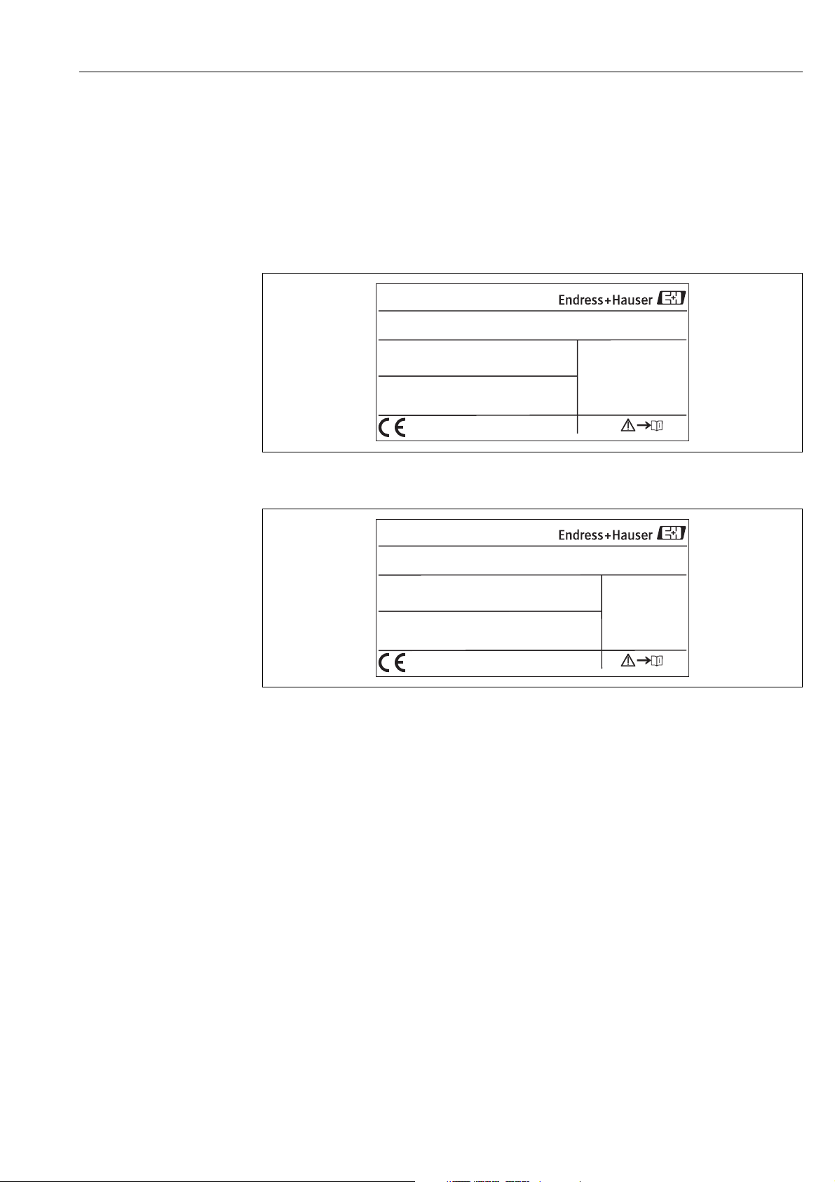
2.1.1 Nameplate
The transmitter and the control unit each has its own nameplate.
Made in Germany, D-70839 Gerlingen
MYCOM S
Order code
Serial no
Meas. range:
Temperature:
Channels:
Output 1:
Output 2:
Mains:
Fig. 1: CPM153 nameplate (example)
pH / Redox
CPM153-A2C10A010
.
55000505G08
-2 ... +16 pH
-50 … +150 °C
1
4 … 20 mA
0/4…20mA
100-230 VAC 50/60 Hz
-1500 mV ... +1500 mV
10 VA
Identification
IP65
-10 < Ta < +55 °C
a0003930
Made in Germany, D-70839 Gerlingen
CPG310
Order code
Serial no
Mains:
CPG310
.
3C000505G09
230 VAC 50/60 Hz
0158
12 VA
IP54
0 < Ta < +55 °C
Fig. 2: CPC310 nameplate (example)
2.1.2 Scope of delivery
The scope of delivery of the system comprises:
• 1 Mycom S CPM153 transmitter
• 1 CPG310 control unit
• 1 rinsing block with securing clamps for assembly
• 4 multihoses
• 2 technical buffer solutions pH 4.00 and 7.00
• 3 double-membrane pumps for conveying cleaner and buffer with canisters
• 1 communication/power supply cable CPG310 / Mycom S CPM153
• 3 level probes, complete with CPG310 cable to canisters
• 1 pressure reduction valve with pressure gauge
•1 water filter
• 1 device identification card
• 1 set of Operating Instructions in English
• Accessories where applicable
If you have any questions, please contact your supplier or sales center.
a0004843
7
Identification
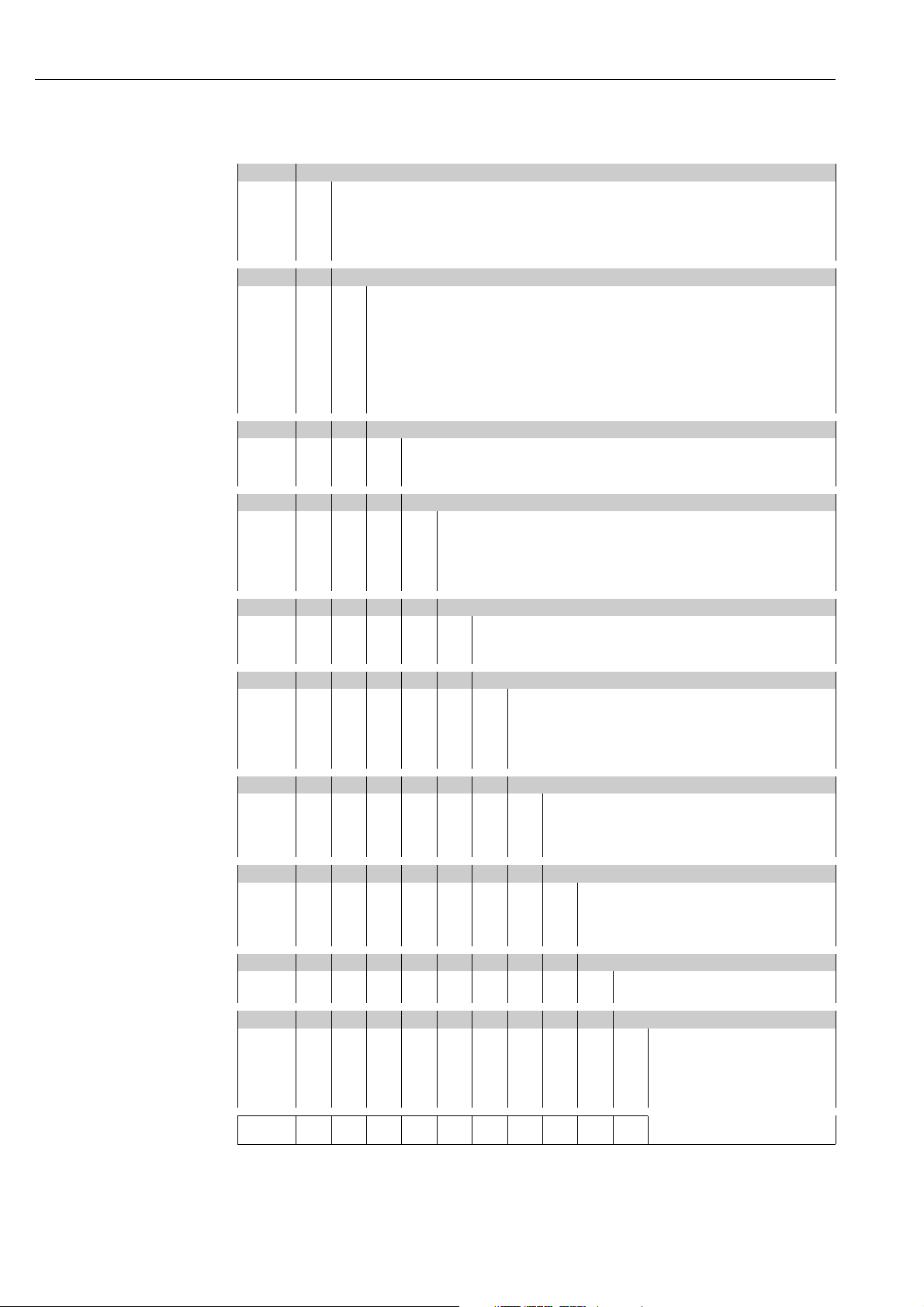
2.1.3 Product structure
Approval
A Basic features: Non-Ex
G With ATEX approval, ATEX II (1) 2G EEx, em ib[ia] IIC T4
O With FM approval Cl. I, Div. 2, with NI input and output circuits, sensor IS Cl. I, Div. 1
P With FM approval Cl. I, Div. 2, with NI input and output circuits
S With CSA approval, Cl. I, Div. 2, sensor IS Cl. 1, Div. 1
Material of rinsing block, O-ring, connection
00 PVDF, Viton, G ¼ male
01 PVDF, Viton, NPT ¼" male
02 PVDF, Kalrez, G ¼ male
03 PVDF, Kalrez, NPT ¼" male
10 Stainless steel 1.4404 (AISI 316L), Viton, G ¼ male
11 Stainless steel 1.4404 (AISI 316L), Viton, NPT ¼" male
12 Stainless steel 1.4404 (AISI 316L), Kalrez, G ¼ male
13 Stainless steel 1.4404 (AISI 316L), Kalrez, NPT ¼" male
Sensor input Mycom S
1 1 measuring circuit for glass electrodes, pH/redox and temperature
2 1 measuring circuit for glass electrodes/ISFET sensors, pH/redox and temperature
5 1 measuring circuit for digital Memosens sensors, pH/redox and temperature
Measurement output Mycom S
A 2 current outputs 0/4 ... 20 mA, passive (Ex and non-Ex)
B 2 current outputs 0/4 ... 20 mA, active (non-Ex)
C HART with 2 current outputs 0/4 ... 20 mA, passive
D HART with 2 current outputs 0/4 ... 20 mA, active
E PROFIBUS PA, without current outputs
Power supply
0 ... 230 V AC
1 110 ... 115 V AC
8 24 V AC / DC
Language
A English / German
B English / French
C English / Italian
D English / Spanish
E English / Dutch
Cable entry
0 Cable glands M20 x 1.5
1 Adapter for cable glands NPT ½"
3 Cable gland M20 x 1.5, PROFIBUS-PA-M12 connector
4 Cable gland NPT ½", PROFIBUS-PA-M12 connector
Length of multihose
05 m
1 5 m with electric heating
210 m
3 10 m with electric heating
Additional equipment
0 Basic version
1 Preparation for CYC310 housing
Setting
A Factory setting
B IQ/OQ template German
C IQ/OQ template English
D Standard FAT German
E Standard FAT English
CPC310- Complete order code
8

Identification
2.2 Certificates and approvals
Declaration of conformity
The product meets the statutory requirements of the harmonized European standards. The
manufacturer certifies compliance with the standards by using the 4 mark.
9
Installation
3 Installation
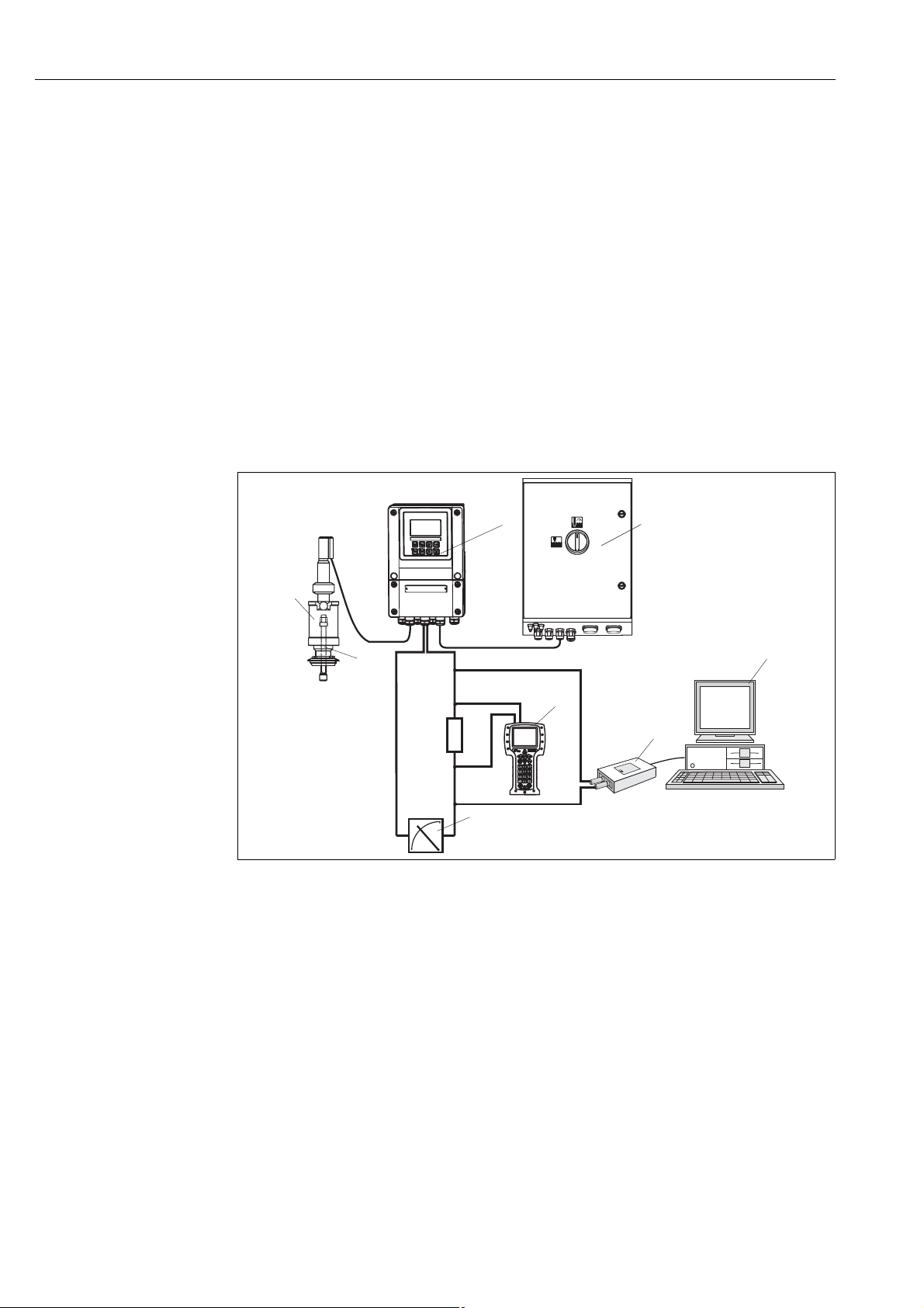
3.1 System setup
A complete system unit comprises:
• Mycom S CPM153 transmitter
• CPG310 control unit
• A rectractable assembly, e.g. CPA475; with or without a potential matching pin (PML)
• A pH/redox sensor: e.g. CPS71 (pH glass), CPS471 (ISFET) or CPS71D (Memosens)
• A measuring cable: CPK9 (pH), CPK12 (ISFET) or CYK10 (Memosens)
•HART
•HART
• PC with FieldCare software (see Accessories) and Mycom DTM
•Recorder
®
handheld terminal DXR375
®
modem Commubox FXA191
Optional:
Fieldgate FXA320 instead of HART
1
2
min.
250 W
Fig. 3: Example of a measuring system
1
Retractable assembly CPA475
2
pH/Redox sensor
3
Mycom S CPM153
4
Topcal S CPC310
®
modem
8
3
7
5
PC with FieldCare
6
HART
HART
7
Recorder
8
4
6
®
modem Commubox FXA191
®
handheld terminal DXR375
5
a0006963
10

Installation
3.2 Incoming acceptance, transport, storage
• Make sure the packaging is undamaged!
Inform the supplier about damage to the packaging.
Keep the damaged packaging until the matter has been settled.
• Make sure the contents are undamaged!
Inform the supplier about damage to the delivery contents.
Keep the damaged goods until the matter has been settled.
• Check that the scope of delivery is complete and matches your order and the shipping documents.
• For storage and transport purposes, pack the instrument so that it is protected against impacts and
humidity. The original packaging offers the best protection. Furthermore, the permitted ambient
conditions must be observed (see "Technical data").
• If you have any questions, please contact your supplier or sales center.
3.3 Installation conditions
3.3.1 Types of mounting
You can choose from the following types of mounting for the individual components:
Device Wall mounting Post/pipe mounting Panel mounting
CPG310 control unit Mounting set included in the
Mycom S CPM153,
protected
Mycom S CPM153,
outdoors
scope of delivery.
Required:
2 screws Ø 6 mm (0.24")
2 wall plugs Ø 8 mm (0.31")
Weather protection cover
CYY102-A required if directly
exposed to weather conditions
(see Accessories).
not applicable not applicable
Mounting set included in
the scope of delivery.
Weather protection cover
CYY102-A and 2x round
post fixtures required (see
Accessories).
Mounting set included in
the scope of delivery.
not usual
11
Installation
MEAS CAL
DIAG
PARAM
?
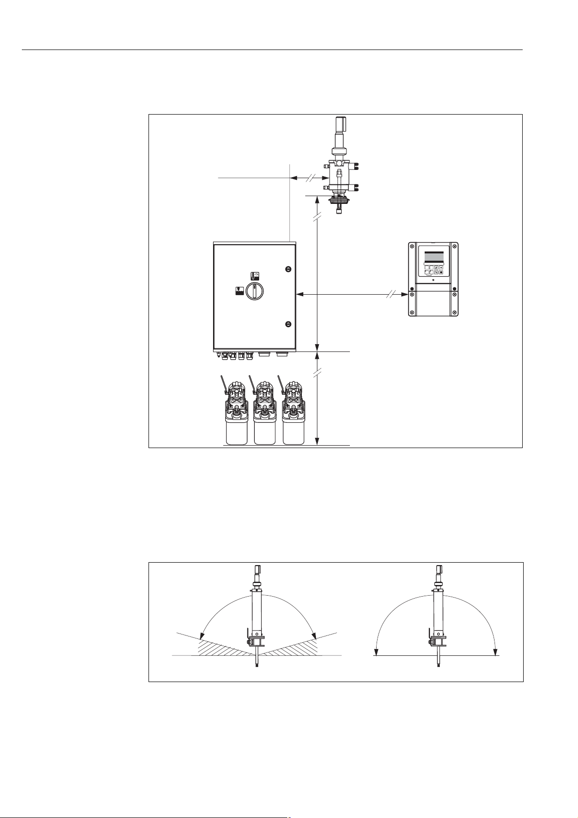
3.3.2 Spacing
The graphic below illustrates the maximum distances between the system components.
max. 5/10 m
(max. 16.4/32.8 ft)**
max. 5 m (16.4 ft)
PARAM
max. 200 m (656 ft)
max. 2.5 m (8.20 ft)*
Fig. 4: Maximum spacing for Topcal S CPC310 system components
* When using the multihoses supplied as standard
** Depending on the multihose version ordered
3.3.3 Assembly installation
A Glass electrode: Installation angle of at least 15 ° to the horizontal.
B ISFET sensor Tophit: No restrictions, 0 ... 180
° recommended
a0006069
12
15°
15°
A
Fig. 5: Permitted orientation depending on the sensor used
B
a0002720
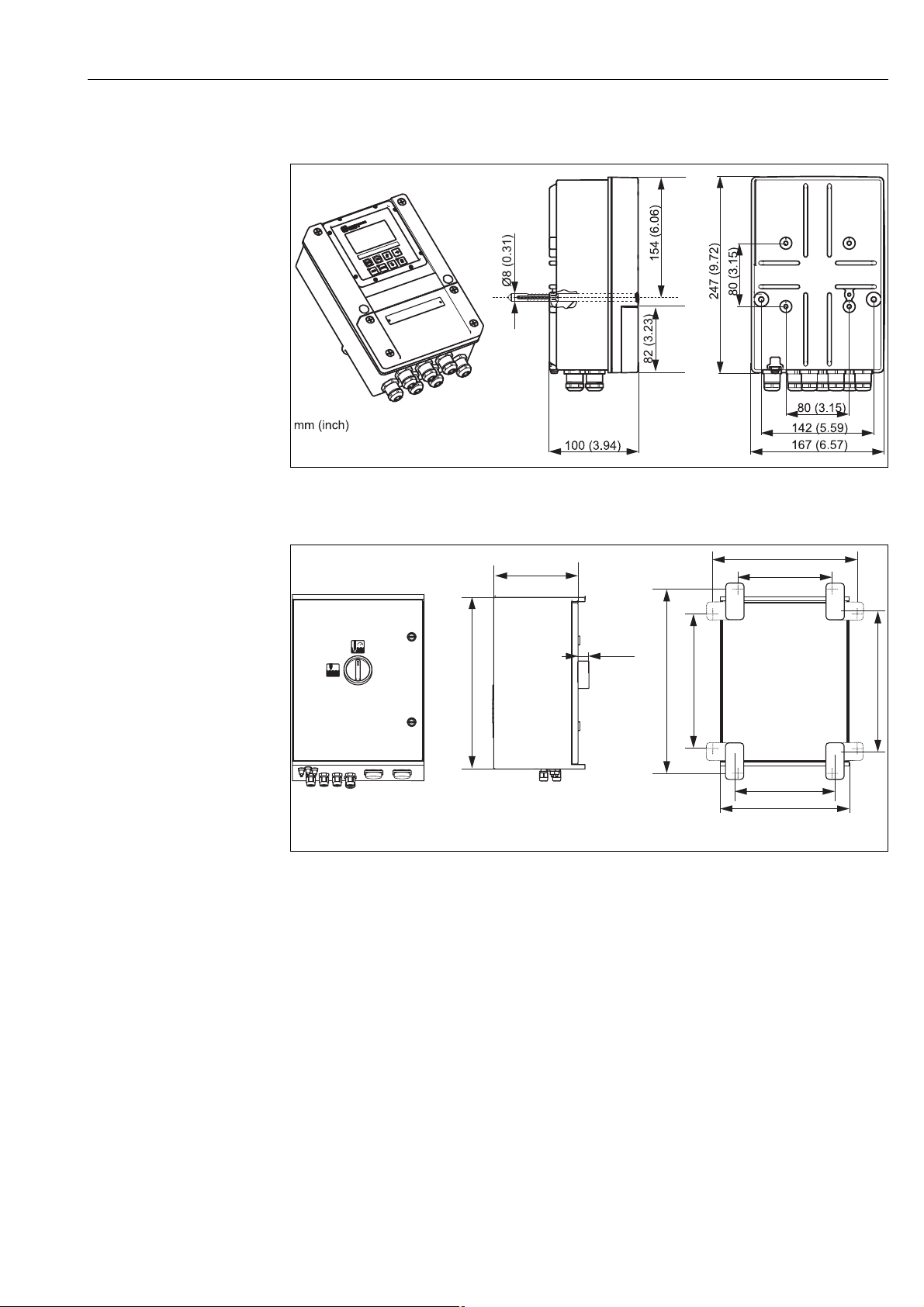
3.3.4 Dimensions
Fig. 6: Dimensions of Mycom S
Installation
cxm153-dim.cdr
200 (7.87)
400 (15.75)
Fig. 7: Dimensions of CPG310 control unit
24
(0.94)
420 (16.54)
327 (12.87)
320 (12.60)
227 (8.94)
350 (13.78)
250 (9.84)
300 (11.81)
mm (inch)
a0005790
13
Installation
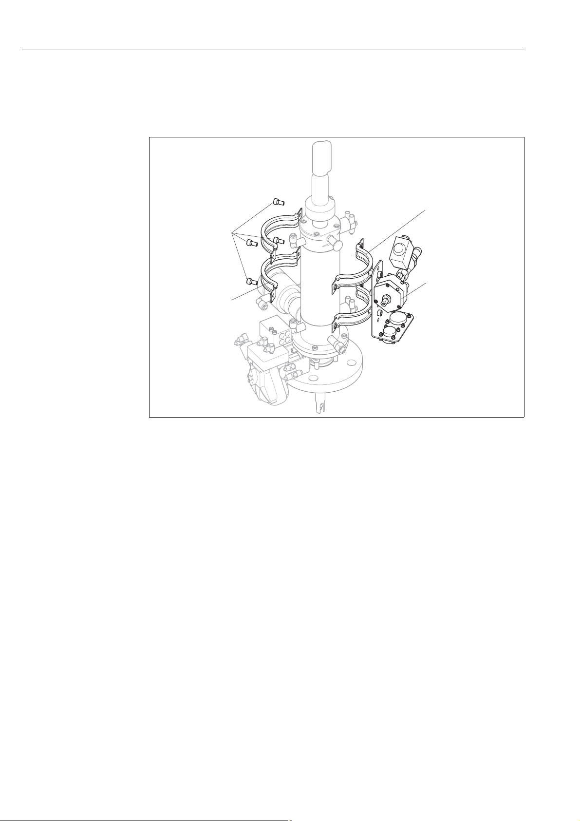
3.4 Installation instructions
3.4.1 Securing rinsing block to assembly
3
1
4
2
a0006202
Fig. 8: Mounting the rinsing block on the assembly (example CPA473)
Proceed as follows to mount the rinsing block:
1. Fit the securing clamps with the rinsing block (3 and 4) on the assembly cylinder.
2. Fit the counterclamps (2) on the assembly cylinder from the other side.
3. Connect the clamps with the screws (1) supplied.
3.4.2 Installation instructions
• The Mycom S transmitter is used as a field device as standard. It can also be installed as a
panel-mounted instrument.
• Mycom S is suitable for wall mounting with securing screws and for post mounting to cylindrical
pipes.
• Always install the transmitter horizontally in such a way that the cable entries are always pointing
downwards.
14
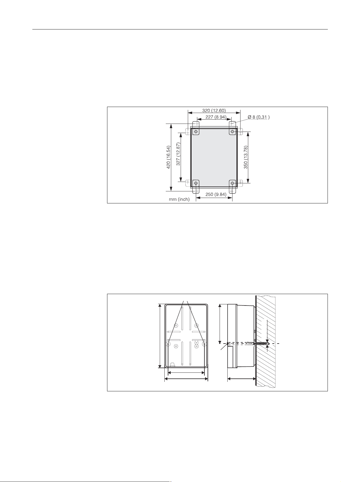
3.4.3 Wall mounting
Caution!
"
• Make sure the maximum permitted ambient temperature range of -20 ... +60
is observed. Avoid direct sunlight.
• Always mount the wall-mount housing in such a way that the cable entries point downwards.
Control unit
°C (-4 ... 140 °F)
Installation
a0004861
Fig. 9: Dimensions for wall mounting with wall securing kit (part of scope of delivery)
Proceed as follows to wall-mount the unit:
1. Please note that the maximum suction height for buffer and cleaner is 2.5 m (8.2 ft.) when
using the standard multihoses supplied. Bore the holes as per the graphic above.
2. Screw the elements of the wall securing set supplied to the rear wall of the housing.
3. Secure the housing to the wall without any inclination.
Transmitter
1
154 (6.06)
247 (9.72)
2
Ø 8 (0.31)
142 (5.59)
167 (5.57)
mm (inch)
Fig. 10: Dimensions for wall mounting, securing screw: Ø 6 mm (0.24"), wall plug: Ø 8 mm (0.31")
1 Securing bores
2 Plastic caps
100 (3.94)
a0003953
15
Installation
Proceed as follows to wall-mount the unit:
1. Bore the holes as per Fig. 10.
2. Push the two securing screws from the front through the securing bores (item 1).
3. Mount the transmitter housing to the wall as illustrated.
4. Cover the bores with the plastic caps (item 2).
3.4.4 Post mounting and panel mounting
!
Note!
You need a special mounting kit to secure the transmitter to horizontal and vertical posts or pipes
(max. Ø 70 mm (2.76")) and for panel mounting.
a0003955
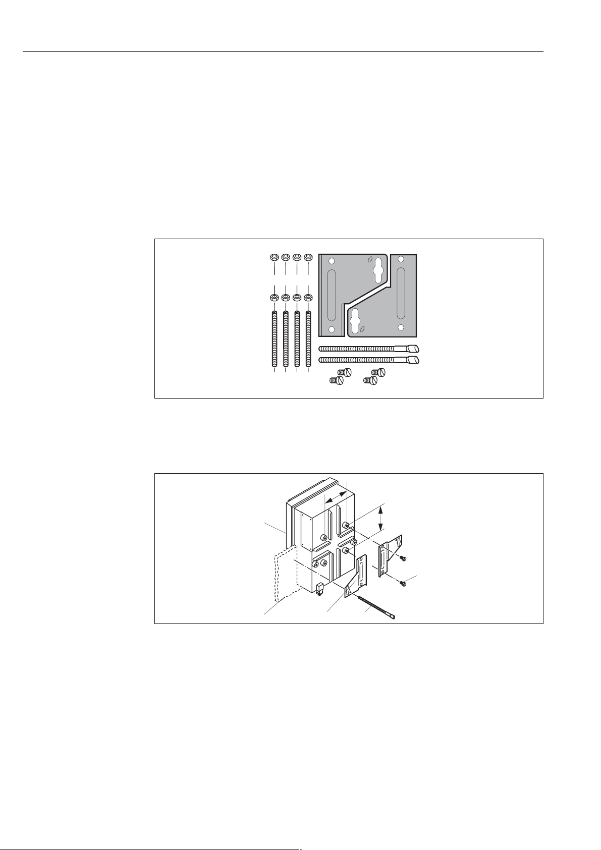
Fig. 11: Mounting kit
Panel mounting
Proceed as follows to panel-mount the transmitter:
80
80
5
4
a0003956
Fig. 12: Panel mounting
1
2
3
1. Make the necessary mounting cutout, measuring 161 x 241 mm (6.34" x 9.49").
The installation depth is 134 mm (5.28").
2. Unscrew the top housing section (item 1).
3. Secure the securing plates (item 3) to the transmitter housing base using the securing screws
(item 5) in accordance with Fig. 12.
4. Secure the transmitter to the panel (item 2) using the clamping screws (item 4).
5. Place the flat seal (see "Accessories" section) on the housing base.
6. Screw the top housing section back on.
16
Post mounting
Proceed as follows to mount the transmitter to a post:
Installation
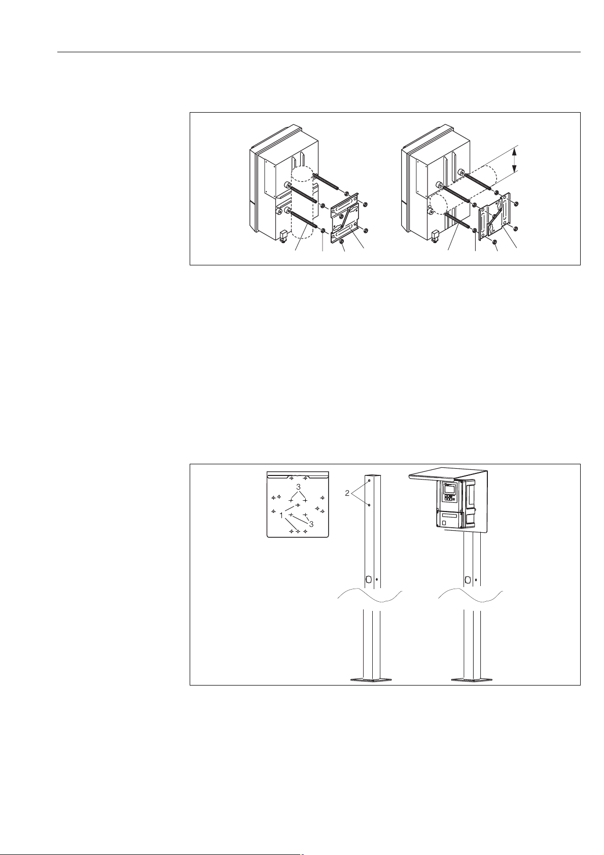
Fig. 13: Post mounting
AVertical mounting
B Horizontal mounting
A
2 3
1
4
B
Ø70
2 3
1
4
a0003954
1. Screw the four securing screws (item 1) into the threaded openings on the transmitter.
2. Counter every securing screw with a nut (item 2).
3. Set the transmitter to the desired position on the post or pipe.
4. Push the securing plates (item 4) onto the securing screws in accordance with Fig. 13.
5. Screw a nut (item 3) onto each securing screw and tighten it so that the transmitter is securely
fastened to the post or pipe.
You can also secure the field device to a square universal post in conjunction with the weather
protection cover. These are available as accessories, see the "Accessories" section.
Fig. 14: Mounting the field device with a universal post and weather protection cover
a0003957
Proceed as follows to mount the weather protection cover:
1. Screw the weather protection cover onto the upright post (bores 2) with 2 screws (bores 1).
2. Secure the field device to the weather protection cover. To do so, use the bores (3).
17

Installation
3.5 Post-installation check
• After installation, check the transmitter and the control unit for damage.
• Check whether the transmitter and control unit are protected against rain and direct sunshine.
18

4 Wiring
Wiring
#
!
Warning!
• The electrical connection must only be carried out by an electrical technician.
• The electrical technician must have read and understood these Operating Instructions and must
adhere to them.
• Before beginning the connection work, ensure no voltage is applied to any cable.
4.1 Electrical connection
4.1.1 Overview
You have the following connection options at your disposal:
• Direct connection to the transmitter via current output 1 (terminals 31 /32)
• Connection via the 4 ... 20 mA circuit
Hinweis!
• Connect unused signal cores of input and output cables to the internal PE rail of the transmitter.
• The current/resistance input may only be connected with a shielded cable, whereby the shield
must be connected to the PE rail of the transmitter.
• Make sure that the grounding in the connection compartment cover is connected to the PE rail
in the housing by means of the PE line.
• The measuring circuit must have a minimum load of 250
• Current output 1 is permanently set to "4 ... 20 mA".
• Without an external power supply, communication via current output 1 is only possible if the
jumper setting is "active".
Ω in current output 1.
19
Wiring
Digital sensor
PE
E1: ext. Hold*
E2: Chemoclean
"Clean"*
E3: Chemoclean
"User"*
Power supply
output*
Alarm relay
(NAMUR: Failure
Relay 1
(NAMUR: Mainten. requ.)
Relay 2
(NAMUR: Function control)
Relay 3
Relay 4
Relay 5
Current
output 1
Current
output 2
S
87
BN
88
WH
GN
96
YE
97
Power supply
(operator supply)
Mycom CPM153
+
81
82
+
93
94
+
89
90
85
+
–
+
+
-
+
-
15 V
86
41
42
47
48
57
58
51
52
54
55
44
45
31
mA
32
33
mA
34
pH electrode or ISFET pH sensor
pH
n.c.
Ref.
PA/
PM
Temp. 1
SS
JJ
11 11
J
12
13
L/L+
N/L–
PE
)
Temp. 1
DRN
SRC
Ref.
12
13
PA/
PM
CPG310
PE
BN
L+
WH
L–
12V DC
GN
A
CPG
YE
B
comm.
10 ... 40 V
+
–
A
B
94
93
+
92
+
91
90
+
89
88
+
87
86
+
85
84
+
83
82
+
81
66
+
65
62
+
61
Assembly
service*
Assembly
measure
n.c.
Automatic stop
bin. 2
bin. 1
bin. 0
Assembly
service
Assembly
measuring
Start programme 1-8
(binary)
L/L+
N/L–
PE
Pneumatic
connection
42
41
46
45
51
52
47
48
pumps
58
57
Control of membrane
P6
P5
P4
P3
Level check
P2
P1
Installation and connection
by operator
Power supply
)
AD6/ID4
Multihose coupling
1
2
Compressed
air supply
4...6bar,
filtered 50 µm,
free of oil and
condensate
Pressurized steam,
water, cleaner
Val ve 1
(optional)
Val ve 2
3
J
Assembly
55
56
1112 13
Feedback measure
Feedback service
71
14
Multihose coupling
2/2-way valve
72
Rinse air
76
75
A
Cleaner
B
Buffer 1
C
Buffer 2
20
n.c.: do not connect!
2
3
5
6
CPA475
Rinse block
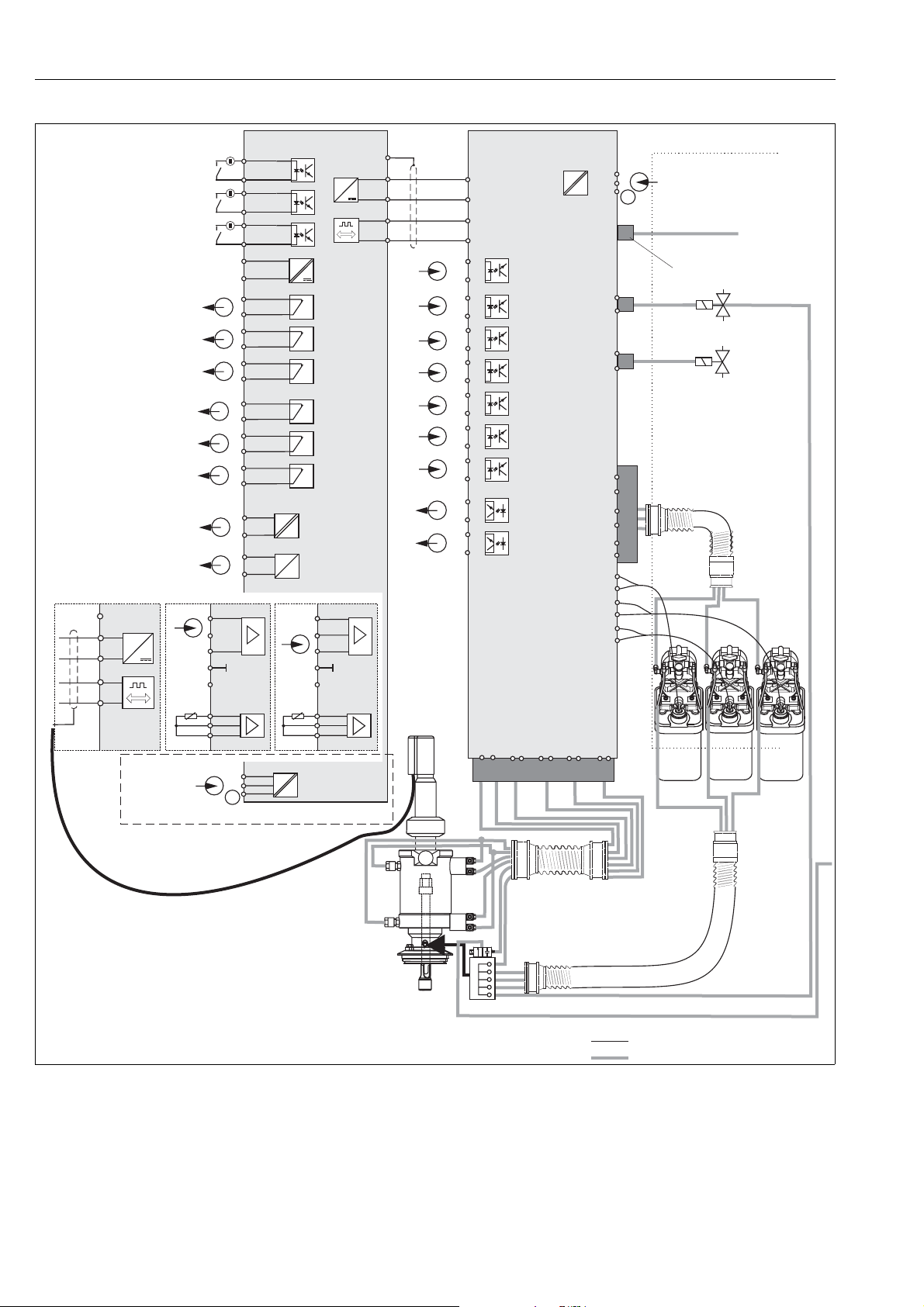
Fig. 15: Connecting in the non-hazardous area
electric line
compressed air/medium
Water
a0005788-en
CPG310
Wiring
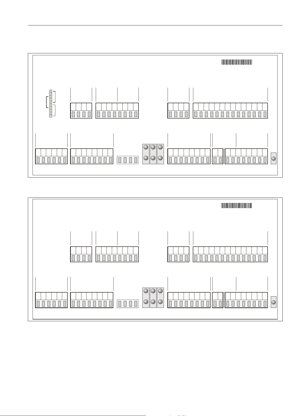
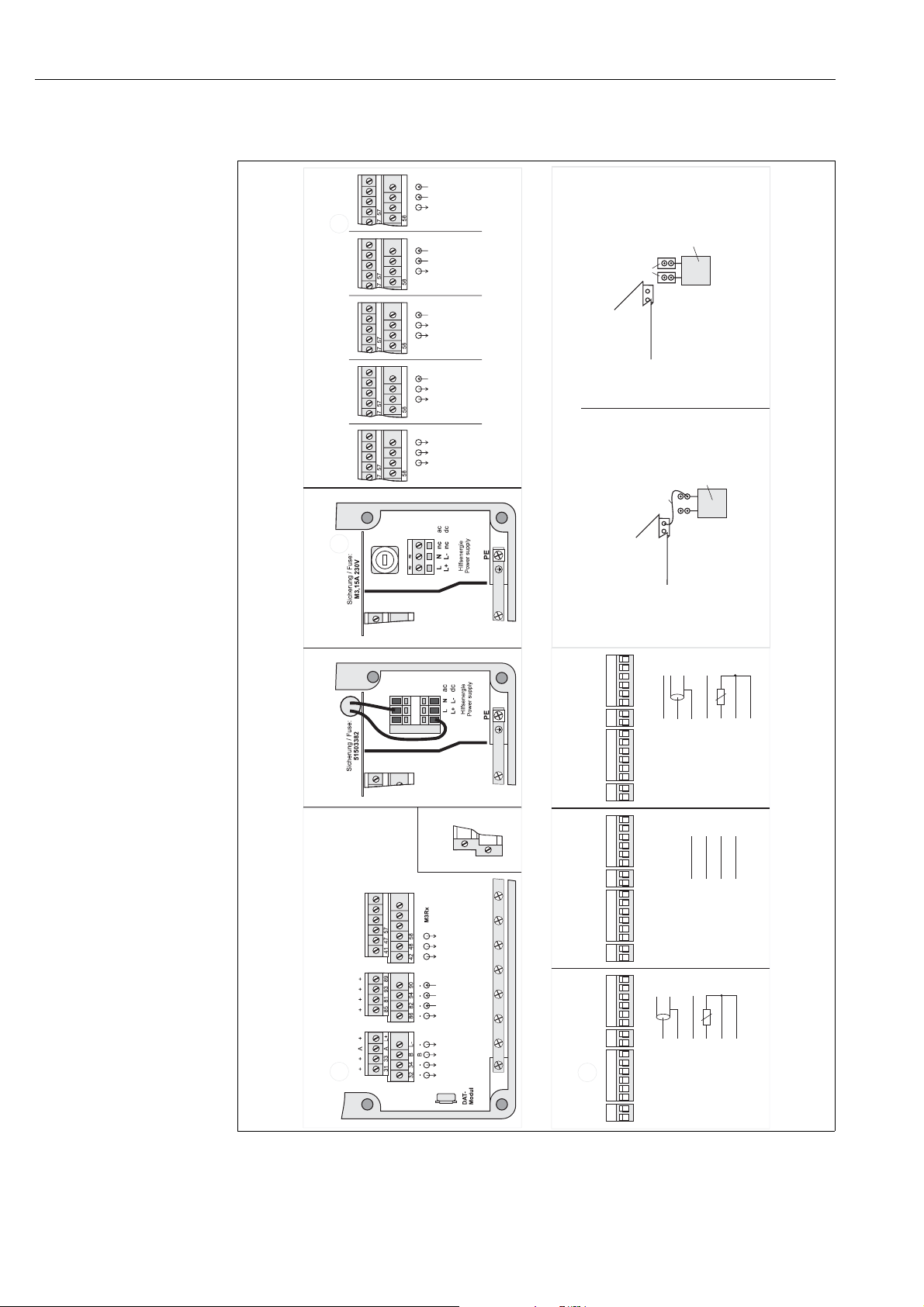
4.1.2 Connection compartment sticker for CPG310 control unit
140107-1000-3A
71027539
100 - 110 - 230 VAC
Zusatzventile /
Jumper
230V
100V/
110V
Power
Sicherung / Fuse:
M3,15A
100-230V
AC
PE
PEL+PEN- PE
gerade Zahlen: minus; ungerade Zahlen: plus; even-numbers: minus; odd-numbers: plus
auxiliary valves
100-230V
Ventil 1 /
valve 1
Ventil 2 /
Puffer 1 /
valve 2
buffer 1
Puffer 2 /
buffer 2
45
46
48 56515752 58
41 42
V1 V2 V3 V4 V9
Interne Eingänge /
n.c.
n.c.
D1
D2P4P1P5P2
47
internal inputs
Puffer 2 /
Puffer 1 /
buffer 1
P3
buffer 2
Reiniger /
cleaner
P6
55
Armatur /
assembly
Reiniger /
V6
cleaner
Fig. 16: Connection compartment sticker for CPG310, 100 /110/ 230 V AC
CPG310
24VAC/DC
Steuer-Ausgänge /
drive outputs
V1
Ass.
Meas.
V2
Mycom
RS485
12V
B
L+ L-
SPS Ausgänge /
61
A
PCS outputs
Service /
service
Messen /
measure
62 72657566 76
Wasser /
71
V7 V8
SPS Eingänge /
PCS inputs
Programmwahl /
program choice
Automatik
Stop /
automatic
bin 1
bin 0
82 9086 9483 91
81 89
Luft /
water
bin 2
85 93
84 9288
Interne Eingänge /
internal inputs
Service-
Schalter /
service
air
K1 K2
S0 S1 S2 S3
stop
87
Druckluft-
sensor /
air pressure
sensor
switch
D4 1311 14
D3
71027540
n.c.
Rückmeldung Armatur /
feedback assembly
Messen /
measure
Service /
Messen /
measure
Service /
service
12
140107-2000-3A
service
Alive-LED
a0006256
Zusatzventile /
auxiliary valves
24V
Reiniger /
cleaner
Armatur /
Ventil 1 /
valve 1
Ventil 2 /
Puffer 1 /
valve 2
buffer 1
45
46
48 56515752 58
41 42
V1 V2 V3 V4 V9
Power
Sicherung / Fuse:
M3,15A
24V
AC/DC
PE
PEL+PEN- PE
gerade Zahlen: minus; ungerade Zahlen: plus; even-numbers: minus; odd-numbers: plus
Interne Eingänge /
n.c.
n.c.
D1
D2P4P1P5P2
47
internal inputs
Puffer 2 /
Puffer 1 /
buffer 1
P3
buffer 2
Reiniger /
P6
Puffer 2 /
buffer 2
cleaner
assembly
55
V6
Fig. 17: Connection compartment sticker for CPG310, 24 V AC/DC
Steuer-Ausgänge /
drive outputs
V1
Ass.
Meas.
V2
Mycom
RS485
12V
B
L+ L-
SPS Ausgänge /
61
A
PCS outputs
Service /
service
Messen /
measure
62 72657566 76
Wasser /
71
V7 V8
SPS Eingänge /
PCS inputs
Programmwahl /
program choice
Automatik
Stop /
automatic
bin 0
bin 1
bin 2
82 9086 9483 91
81 89
water
85 93
84 9288
Interne Eingänge /
internal inputs
Service-
Schalter /
Luft /
service
air
K1 K2
S0 S1 S2 S3
stop
87
Druckluft-
sensor /
air pressure
sensor
switch
D4 1311 14
D3
n.c.
Rückmeldung Armatur /
feedback assembly
Messen /
measure
Service /
Messen /
measure
Service /
service
12
service
Alive-LED
a0006257
21
Wiring
4.1.3 Connection compartment sticker, Mycom S CPM153
Kontakte, contacts, order code*Best.-Variante /
non EX
-..5..
-..4..
-..3..
-..2..
-..1..
+
+
+
+
+
+
-
22
-
51 23 21
52 24
-
22
-
51 23 21
52 24
-
22
51 54 21
52 55
-
22
51 54 21
52 55
45
51 54 44
52 55
0-1k /10k
WW
4-20mA
4-20mA
4-20mA
WW
0-1k /10k
4-20mA
Relay contact 3
Klemmen (Rückseite) /
terminals (back side)
Relay contact 3
Relay contact 4
Relay contact 3
Steckbrücken entsprechend der Zeichnung hinten an den Klemmen
Relay contact 4
Relay contact 3
Relay contact 5
Relay contact 4
Relay contact 3
4.
Steckbrücken /
jumpers
Transmittermodul /
transmitter module
aufstecken. /
Plug the jumpers onto the back side of the terminals as shown below.
Verbindungsleitung /
connecting line
Sensorkabel entsprechend ISFET-Belegung anschließen. /
Connect sensor cable according to ISFET assignment.
Gehäuse-Oberteil des CPM 153 wieder schließen. /
Close the housing cover of the CPM 153.
6.
5.
Klemmen (Rückseite) /
terminals (back side)
Wechsel Glas auf ISFET / Changing from glass to ISFET
Transmittermodul /
transmitter module
Gehäuse-Oberteil des CPM 153 öffnen. /
Gehäuse-Unterteil des CPM153 öffnen und Leitungen des
Open the housing cover of the CPM 153.
Sensorkabels von Klemmen am Gehäusedeckel abziehen. /
Open the lower housing section of the CPM153 and remove the
wires of the sensor cable from the terminals in the housing cover.
2.
1.
Verbindungsleitung zwischen Rückseite Klemme und
Transmittermodul entfernen. /
Remove the line connecting the terminal back side and
the transmitter module.
3.
N
F
L
F
EX
zusammengehörige
Klemmen /
combined clamps
Relay contact 2
Relay contact 1
Alarm contact
CPM153
Stromausgang / current out / Hart
E3: CC "User"
E2: CC "Clean"
E1: ext.Hold
15V 9mA
CPC Supply
CPC RS485
I2: 0-20mA
I1: 0-20mA / Hart
135042-0001-4C
Fig. 18: Connection compartment sticker, Mycom S CPM153
DRN Drain
SRC Source
REF Reference
* Only order version -..1.. is applicable
ISFET
digital sensor
Digitaler Sensor /
Glaselektrode / glass electrode
S
11
12 13
PA
REF
Kanal / channel 2
DRN SRC
S
11
13
12
PA
REF
Kanal / channel 1
DRN SRC
97 96 88 87 S
NC
Kanal / channel 2
NC NC
97 96 88 87 S
NC
Kanal / channel 1
NC NC
S
11
12 13
PA
REF
Kanal / channel 2
PH
S
11
13
12
PA
REF
Kanal / channel 1
PH
rot / red
DRN
pH / mV
braun / brown
Koax / coax
SRC
PA
REF
gelb / yellow
grün / green
97
96
braun / brown
grün / green
Koax / coax
PA
11
REF
grün / green
11
weiß / white
88
gelb / yellow
12
()gelb / yellow
12
braun / brown
87
weiß / white
13
Pt1000
weiß / white
13
Schirm auf PE / screen to PE
Pt100 / Pt1000
a0006259
22
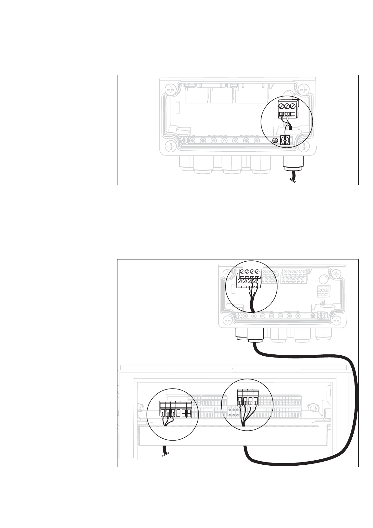
4.1.4 Power supply and communication connection between
transmitter and control unit
N
L
L-
L+
-
+
Fig. 19: Connecting power supply Mycom S
Wiring
a0003960
Mycom S power supply:
1. Guide the power cable through the right Pg cable gland and into the Mycom housing.
2. Connect the green/yellow core to the PE terminal.
3. Connect the two other cable cores to terminals "L" and "N".
BN
GN
YE WH
3133AL+
34 B
32
L-
WH
GN
BN
YE
L+L- B A
PE
PE PE
N-
PE
L+
Fig. 20: Connecting power supply for control unit and communication connection
a0004875
23
Wiring
Control unit power supply
1. Guide the voltage cable through a suitable Pg gland and into the control unit housing.
2. Connect the green/yellow core to the PE terminal.
3. Connect the two other cable cores to terminals "L+" and "N-" (bottom terminal block, left).
Communication connection between Mycom and control unit
1. Guide the end of the communication cable with the black shield wire through a suitable Pg
gland on Mycom.
2. Guide the other end of the communication cable through a Pg gland on the control unit.
3. Connect the cable cores as follows:
Cable core Mycom connection Control unit connection
Yellow (YE) Terminal B Terminal B
Green (GN) Terminal A Terminal A
White (WH) Terminal L- Terminal L-
Brown (BN) Terminal L+ Terminal L+
Black (BK) PE grounding bar n.c.
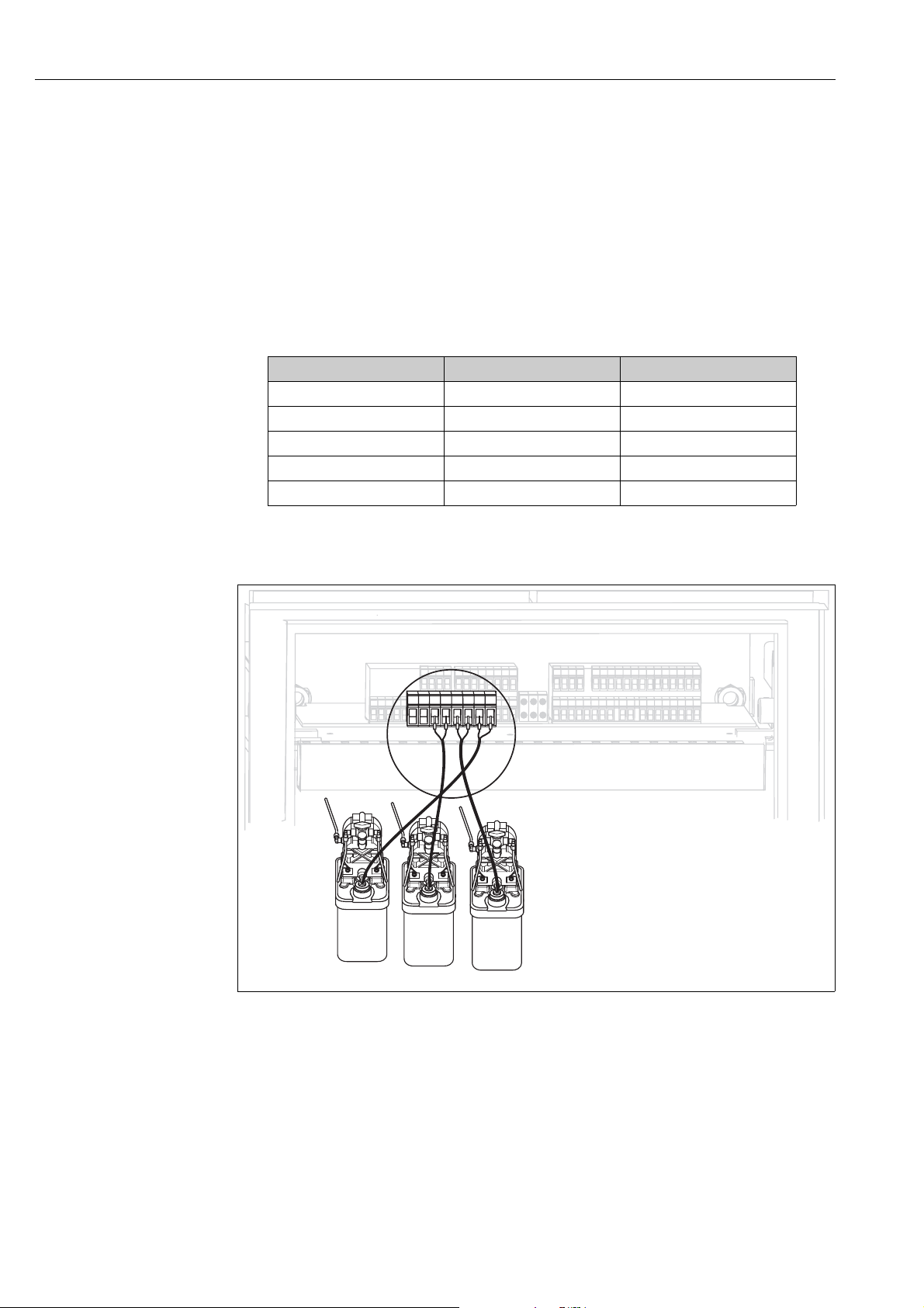
4.1.5 Level probes for buffer and cleaner
D1 D2 P1 P2 P3 P4 P5 P6
A
Fig. 21: Connecting level probes for buffer and cleaner
ACleaner
B Buffer 1
C Buffer 2
B
C
a0005835
24
Wiring
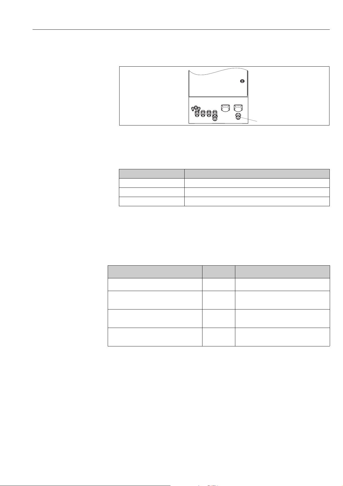
1. Guide the cables of the level probes for the buffer and cleaner through the threefold Pg gland
behind the multihose connection (see Fig. 22).
1
Fig. 22: Guiding the level probe cable
1 Threefold Pg gland
a0006021
2. Connect the cable cores as follows. Polarity does not matter here:
Cable core Control unit connection
Level probe, buffer 1 Terminal P1 and P2
Level probe, buffer 2 Terminal P3 and P4
Level probe, cleaner Terminal P5 and P6
4.1.6 Analog sensors
Measuring cables
You require shielded special measuring cables to connect pH and redox sensors to the transmitter.
You can use the following multicore and preterminated cable types:
Sensor type Cable Extension
Electrode without temperature sensor CPK1 VBA / VBM box + CYK71 cable
!
Electrode with Pt 100 temperature sensor and
TOP68 plug-in head
ISFET sensor with Pt 100 / Pt 1000 temperature
sensor and TOP68 plug-in head
pH individual electrode with separate reference
electrode and separate temperature sensor
CPK9 VBA / VBM box + CYK71 cable
CPK12 VBA / VBM box + CYK12 cable
CPK2 VBA / VBM box + PMK cable
Note!
Further information on the cables and junction boxes can be found in the "Accessories" section.
25
Wiring
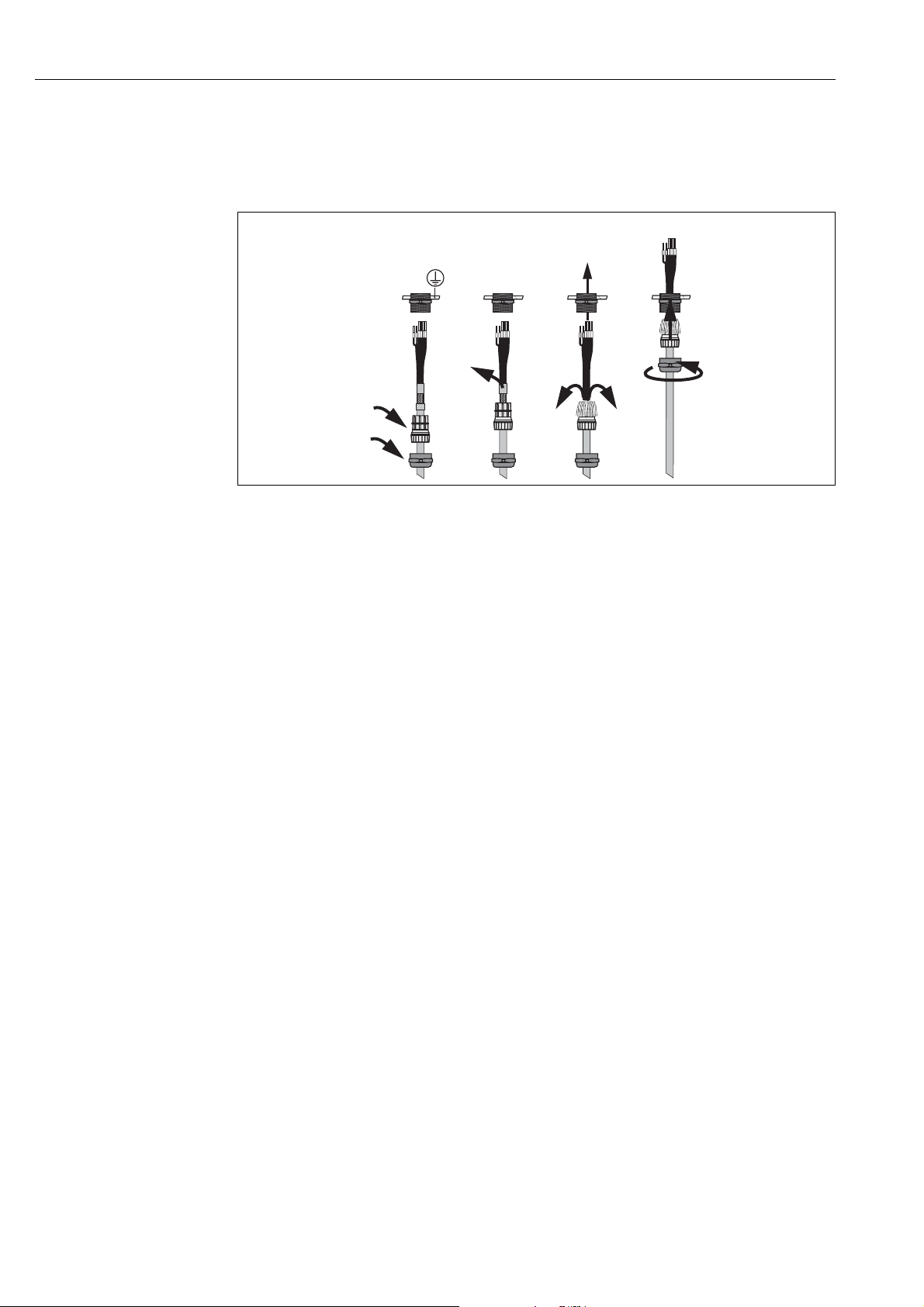
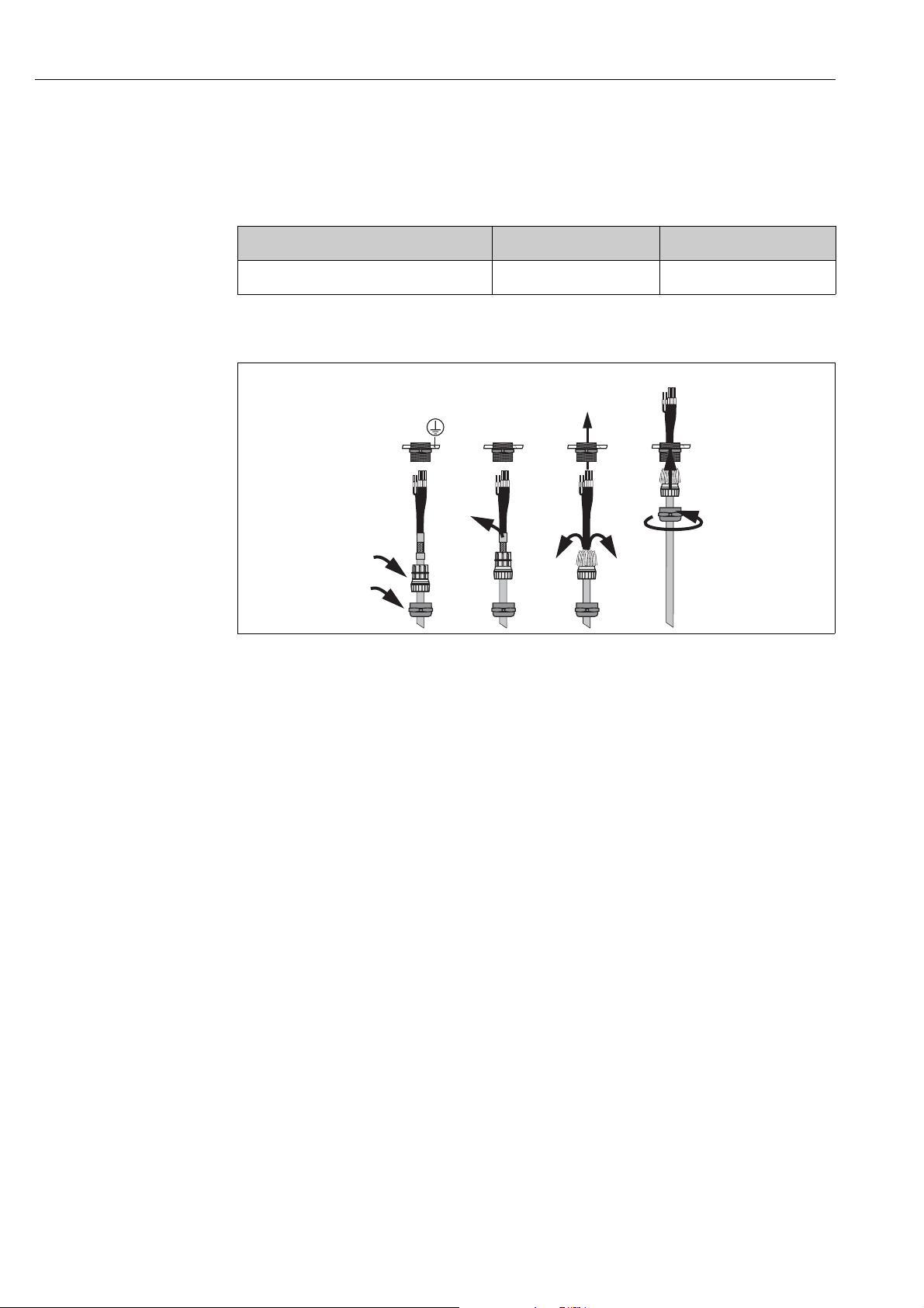
Preparing cables
Caution!
"
Danger of inaccuracy.
Make sure to protect connectors, terminals and cables against moisture.
1
Fig. 23: Outer screen connection with metal cable gland
2
3
4
a0003976
1. Slide the cable gland and the clamping ring over the cable.
2. Remove the inner insulation.
3. Remove the outer shield from the cable and fold it back over the clamping ring.
4. Guide the sensor cable through the cable opening of the device and screw the gland closed.
Shield contacting takes place automatically here.
26
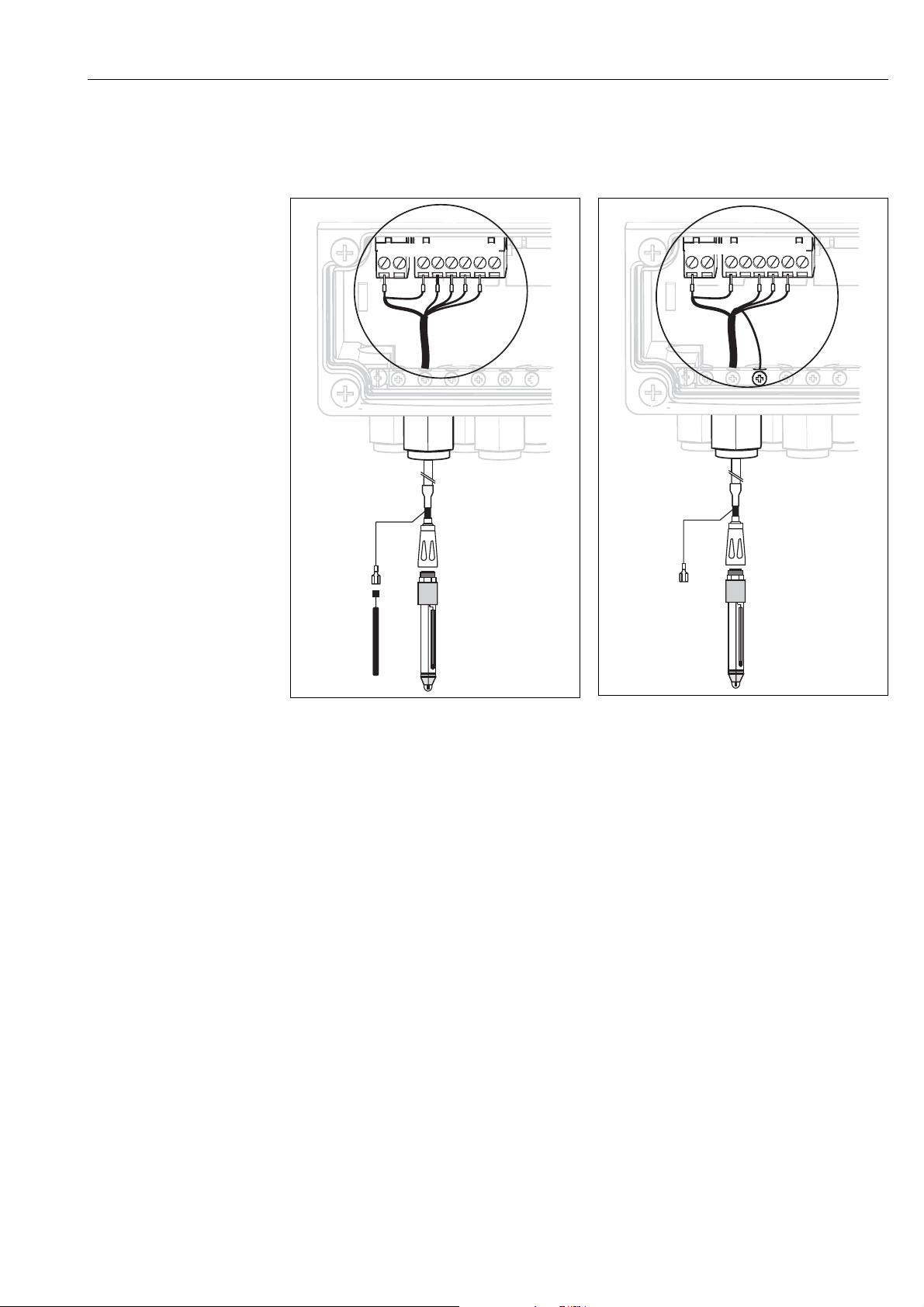
pH/redox glass electrodes
Connect the cable cores in the device as follows:
Connection with PML (symmetrical) Connection without PML (unsymmetrical)
Wiring
BN
PA/PM
pH
WH
Coax
Ref
BK
PA
BN
pH
WH
Ref
BK
Coax
11
12
13
S
WH
GN
YE
BN
d.n.c
PA
BN
11
12
13
S
WH
GN
YE
!
a0003961
Fig. 24: Connecting pH glass electrode with PML
Fig. 25: Connecting pH glass electrode without PML
d.n.c (do not connect)
Note!
• The yellow (YE), white (WH) and green (GN) cable cores do not apply when using CPK1.
• The outer shield of the cable is grounded by means of the metal gland.
• More information on pH measurement with PML and without PML is provided on the
"Additional information" CD-ROM supplied.
a0003962
27
Wiring
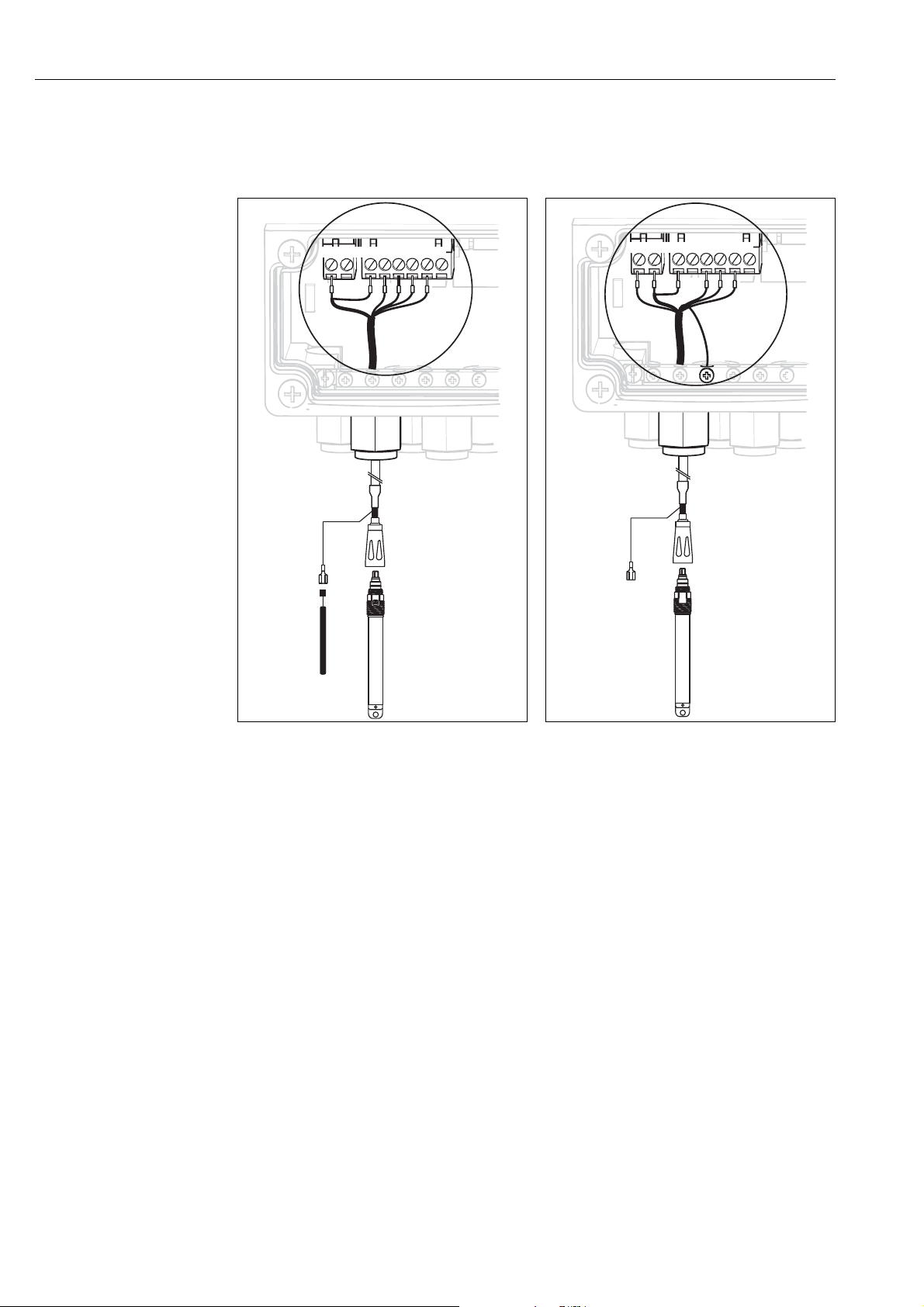
ISFET sensors
Connect the cable cores in the device as follows:
Connection with PML (symmetrical) Connection without PML (unsymmetrical)
11
12
Ref
DRN
SRC
Ref
DRN
11
12
13
PA
S
SRC
13
PA
S
!
BK
BN
YE
WH
GN
WH
Coax
BN
PA/PM
Fig. 26: Connecting ISFET sensors with PML
WH
RD
Coax
BN
d.n.c
a0003963
Fig. 27: Connecting ISFET sensors without PML
BK
BN
YE
WH
GN
a0003964
d.n.c (do not connect)
Note!
• The outer shield is grounded by means of the metal gland.
• More information on pH measurement with PML or without PML is provided on the "Additional
information" CD-ROM supplied.
28
Changing the pH input from glass electrode to ISFET sensor
In the glass/ISFET version (CPC310-xx2xxxxxxx), Topcal S is supplied for measuring with glass
electrodes as standard.
Proceed as follows to switch the connection:
1. Open the bottom housing section of the device.
2. If a glass electrode is connected, disconnect the cores of the sensor cable.
3. Remove the "pH" terminal on the housing cover (see Fig. 28) from the device and replace it
with the "DRN/SRC" terminal supplied.
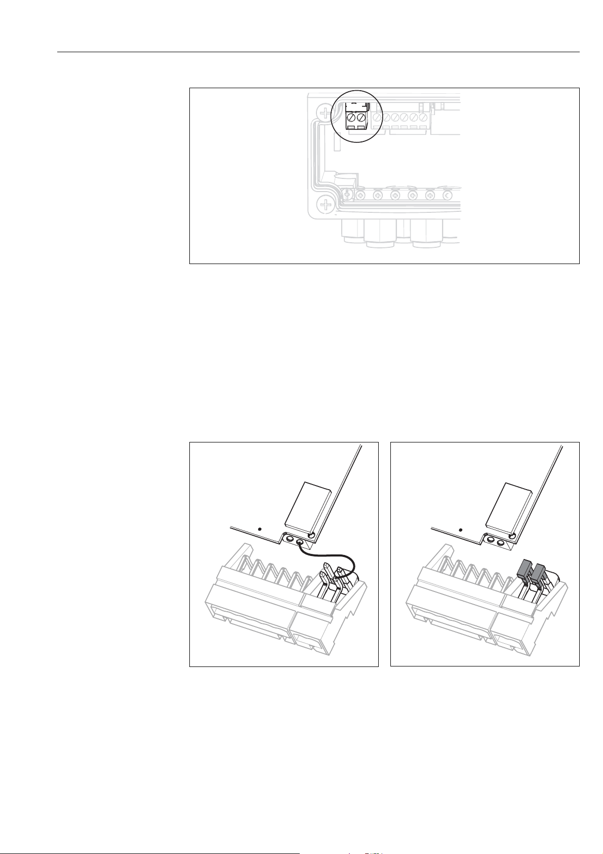
Wiring
pH
pH
Ref
11
12
13
PA
S
a0003977
Fig. 28: pH terminal on housing cover
4. Open the top housing section of the device.
5. On the right-hand side of the housing cover, disconnect the red cable to the pH input at both
ends (see Fig. 29).
!
6. Attach the jumpers supplied as illustrated in Fig. 30.
7. Connect the sensor cable in accordance with the ISFET assignment.
8. In the Quick Setup, change the electrode type to "ISFET".
Note!
Proceed accordingly for changing from ISFET sensors to glass electrodes.
Fig. 29: pH input module in the housing cover with
cable (red) for connecting glass electrodes
a0003978
Fig. 30: pH input module in the housing cover with
jumper for connecting ISFET sensors
a0003979
29
Wiring
4.1.7 Digital sensors with Memosens technology
Measuring cables
You require the Memosens CYK10 data cable to connect digital sensors:
Sensor type Cable Extension
Digital sensors with temperature sensor CYK10 RM junction box + CYK81 cable
Preparing cables
1
Fig. 31: Outer screen connection with metal cable gland
2
3
4
a0003976
1. Slide the cable gland and the clamping ring over the cable.
2. Remove the inner insulation.
3. Remove the outer shield from the cable and fold it back over the clamping ring.
4. Guide the sensor cable through the cable opening of the device and screw the gland closed.
Shield contacting takes place automatically here.
30
 Loading...