

Page 1
TI01443T/09/EN/01.18
71432308
2018-12-20
Products Solutions Services
Technical Information
iTHERM
MultiSens Bundle TMS31
Metallic flexible rope multipoint for silos and
storage tank applications
Application
• Oil storage tanks
• Bulk material silos
Your benefits
• Easy installation and process integration thanks to a high degree of customization
• Flexible rope that adapts to different silos or tank operating conditions (filling,
emptying, storage, …)
• Intrinsically safe components for use in Ex areas
• Highly robust design for a long product lifetime and continuous monitoring in all
conditions
Page 2

Table of contents
iTHERM MultiSens Bundle TMS31
Function and system design ................... 3
Measuring principle ............................ 3
Measuring system ............................. 3
Equipment architecture ......................... 4
Input ..................................... 6
Measured variable ............................. 6
Measuring range .............................. 6
Output ................................... 6
Output signal ................................ 6
Family of temperature transmitters ................. 7
Power supply .............................. 7
Wiring diagrams .............................. 7
Performance characteristics .................. 10
Accuracy .................................. 10
Influence of ambient temperature ................. 11
Response time .............................. 11
Shock and vibration resistance .................... 11
Calibration ................................. 11
Installation ............................... 12
Mounting location ............................ 12
Orientation ................................ 12
Installation instructions ........................ 12
Material certification .......................... 21
Test report and calibration ...................... 21
Ordering information ....................... 22
Accessories ............................... 25
Device-specific accessories ...................... 25
Communication-specific accessories ................ 26
Service-specific accessories ...................... 26
Documentation ............................ 27
Environment .............................. 13
Ambient temperature range ..................... 13
Storage temperature .......................... 13
Humidity .................................. 13
Climate class ............................... 14
Degree of protection .......................... 14
Electromagnetic compatibility (EMC) ............... 14
Process .................................. 14
Process temperature range ...................... 14
Process pressure range ......................... 14
Mechanical construction .................... 14
Design, dimensions ........................... 14
Weight ................................... 19
Materials .................................. 19
Process connection ........................... 20
Operability ............................... 20
Certificates and approvals ................... 21
CE Mark .................................. 21
Hazardous area approvals ....................... 21
Certification HART ........................... 21
Certification FOUNDATION Fieldbus ................ 21
Certification PROFIBUS® PA ..................... 21
Other standards and guidelines ................... 21
2 Endress+Hauser
Page 3

iTHERM MultiSens Bundle TMS31
Function and system design
Measuring principle Thermocouples (TC)
Thermocouples are comparatively simple, robust temperature sensors which use the Seebeck effect
for temperature measurement: if two electrical conductors made of different materials are connected
at a point, a weak electrical voltage can be measured between the two open conductor ends if the
conductors are subjected to a thermal gradient. This voltage is called thermoelectric voltage or
electromotive force (emf.). Its magnitude depends on the type of conducting materials and the
temperature difference between the "measuring point" (the junction of the two conductors) and the
"cold junction" (the open conductor ends). Accordingly, thermocouples primarily only measure
differences in temperature. The absolute temperature at the measuring point can be determined
from these if the associated temperature at the cold junction is known or is measured separately and
compensated for. The material combinations and associated thermoelectric voltage/temperature
characteristics of the most common types of thermocouple are standardized in the IEC 60584 and
ASTM E230/ANSI MC96.1 standards.
Resistance thermometer (RTD)
These resistance thermometers use a Pt100 temperature sensor according to IEC 60751. The
temperature sensor is a temperature-sensitive platinum resistor with a resistance of 100 Ω at
0 °C (32 °F) and a temperature coefficient α = 0.003851 °C-1.
There are generally two different kinds of platinum resistance thermometers:
• Wire wound (WW): Here, a double coil of fine, high-purity platinum wire is located in a ceramic
support. This is then sealed top and bottom with a ceramic protective layer. Such resistance
thermometers not only facilitate very reproducible measurements but also offer good long-term
stability of the resistance/temperature characteristic within temperature ranges up to
600 °C (1 112 °F). This type of sensor is relatively large in size and it is comparatively sensitive to
vibrations.
• Thin film platinum resistance thermometers (TF): A very thin, ultrapure platinum layer,
approx. 1 μm thick, is vaporized in a vacuum on a ceramic substrate and then structured
photolithographically. The platinum conductor paths formed in this way create the measuring
resistance. Additional covering and passivation layers are applied and reliably protect the thin
platinum layer from contamination and oxidation, even at high temperatures. The primary
advantages of thin film temperature sensors over wire wound versions are their smaller sizes and
better vibration resistance. A relatively low principle-based deviation of the resistance/
temperature characteristic from the standard characteristic of IEC 60751 can frequently be
observed among TF sensors at high temperatures. As a result, the tight limit values of tolerance
category A as per IEC 60751 can only be observed with TF sensors at temperatures up to approx.
300 °C (572 °F). For this reason, thin-film sensors are generally only used for temperature
measurements in ranges below 400 °C (752 °F).
Measuring system
Endress+Hauser offers a complete portfolio of optimized components for the temperature measuring
point – everything you need for the seamless integration of the measuring point into the overall
facility.
This includes:
• Power supply unit/active barrier
• Configuration units
• Overvoltage protection
For more information, see the brochure 'System Components - Solutions for a Complete
Measuring Point' (FA00016K/09)
Endress+Hauser 3
Page 4
iTHERM MultiSens Bundle TMS31
2 3
4
7
1
5
6
A0038295
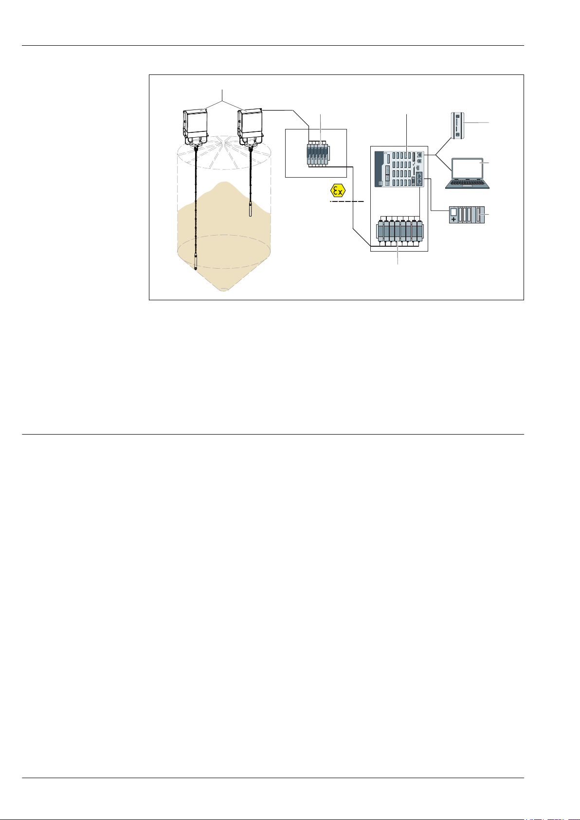
1 Application example in a silo.
1 Mounted multipoint thermometer, optionally with built-in transmitters in the junction box for 4 to 20 mA-,
HART-, PROFIBUS® PA-, FOUNDATION Fieldbus™ communication or terminal blocks for remote wiring.
2 TMT82 or other Ex approved transmitters
3 RSG45 with data recording, calculation, logic control, limit monitoring, alarms and events
4 Edge device
5 Device configuration with application software FieldCare
6 Fieldbus to DCS/PLC
7 Active barrier RN221N (24 VDC, 30 mA) that has a galvanically isolated output for supplying voltage to loop-
powered transmitters. The universal power supply works with an input supply voltage of 20 to 250 V DC/AC;
50/60 Hz, which means that it can be used in all international power grids.
Equipment architecture
The multipoint thermometer belongs to a range of modular product configuration for multipoint
temperature detection with a design where subassemblies and components can be managed
individually for easy maintenance and spare part ordering.
The temperature probe-only version consists of many sub-assemblies:
• Insert
• Rope
• Weight
• Process connection
• Neck (see below for a more detailed description)
In general the instrument measures the temperature profile inside the process environment by
means of many sensors wrapped around a rope, jointed to a suitable process connection which
ensures the right tightness level.
The temperature probe + diagnostic version combines the temperature probe with a head
transmitter, which is available with enhanced accuracy and reliability compared to directly wired
sensors. Output communication protocols available are: Analog output 4 to 20 mA, HART®,
4 Endress+Hauser
Page 5
iTHERM MultiSens Bundle TMS31
1
2b
4
8
3
5
2a
6
7
10b
9
9
11
10a
9
11
2c
PROFIBUS® PA, FOUNDATION Fieldbus™. Externally the extension cables are wired into the junction
box, which can be directly mounted or remotely as an option.
Design
A0038296
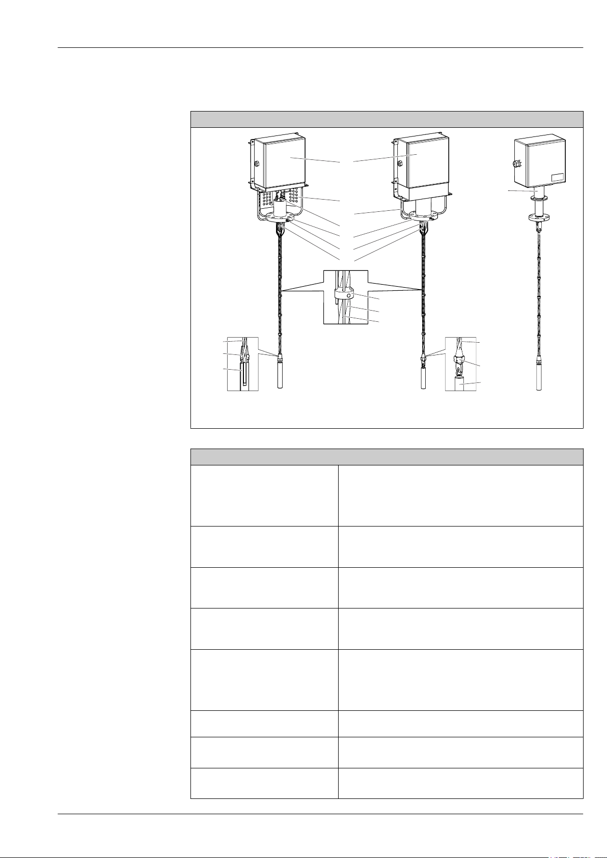
2 MultiSens Bundle design with open support on the left side, MultiSens Bundle design with open frame
with protection in the middle and tube neck design on the right side
Description and available options
Hinged cover junction box for electrical connections. It includes
components such as electrical terminals, transmitters and cable
1: Head
2a: Open supporting frame
2b: Supporting frame with cover
2c: Tube neck
3: Compression fitting
4: Process connection
5: Eyebolt
6: Toggle joint
glandes.
• 316/316L
• Other materials on request
Modular frame support that is adjustable for all available junction
boxes.
316/316L
Modular support that is adjustable for all available junction boxes
and ensures extension cable inspection.
316/316L
Modular tube frame support adjustable for all available junction
boxes
316/316L
High reliability for tightness between process and external
environment, for a wide range of process fluids concentration and
severe combination between temperature and pressure.
• 316L
• 316H
Represented by a flange according to international standards, or
engineered to satisfy specific process requirements. → 20
Lifting device for easy handling during installation phase.
316
Connection between the rope and the process connection.
316
Endress+Hauser 5
Page 6
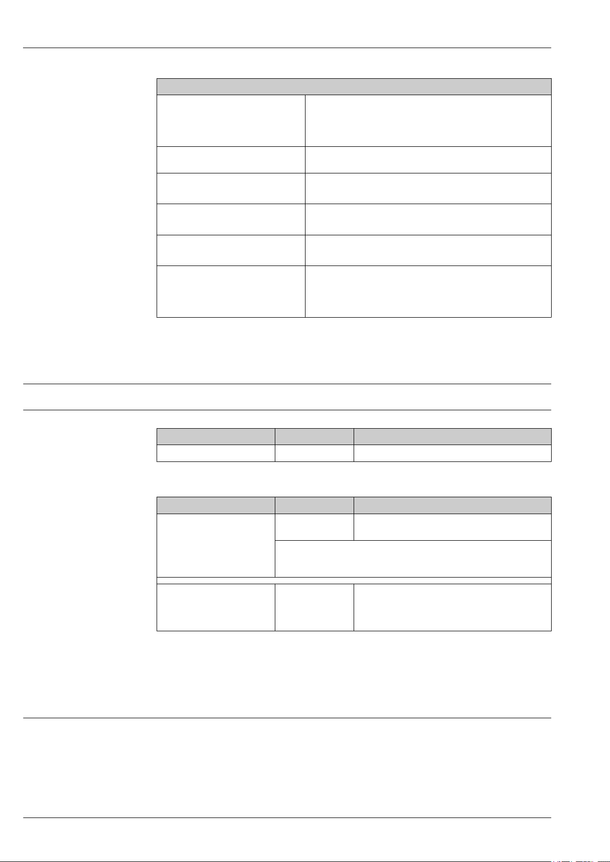
Description and available options
7: Ogives
8: Insert
9: Rope
10a: Swage eye
10b: Metric swage thread
11: Weight
iTHERM MultiSens Bundle TMS31
Insert guide for the correct positioning of the measuring sensing
element.
• 316
• 316L
Thermocouple (type J, K) grounded and ungrounded execution or
RTD (Pt100 wire wound).
Metallic rope.
316
Ring-bolt end connection.
316
Threaded end connection.
316
Weight to maintain the rope pretensioned and in a straight position
during working condition (i.e. tank filling).
• 316
• 316L
Measured variable
Measuring range
Input
Temperature (temperature linear transmission behavior)
RTD:
Input Designation Measuring range limits
RTD as per IEC 60751 Pt100 –200 to +600 °C (–328 to +1 112 °F)
Thermocouple:
Input Designation Measuring range limits
Thermocouples (TC) as per IEC
60584, part 1 - using an
Endress+Hauser - iTEMP
temperature head transmitter
Thermocouples (TC) - flying
leads - as per IEC 60584 and
ASTM E230
1) Limited by jacket material of insert
Type J (Fe-CuNi)
Type K (NiCr-Ni)
Internal cold junction (Pt100)
Cold junction accuracy: ± 1 K
Max. sensor resistance: 10 kΩ
Type J (Fe-CuNi)
Type K (NiCr-Ni)
–40 to +520 °C (–40 to +968 °F)
–40 to +800 °C (–40 to +1 472 °F)
–210 to +520 °C (–346 to +968 °F), typical sensitivity
above 0 °C ≈ 55 μV/K
–270 to +800 °C (–454 to +1 472 °F)
sensitivity above 0 °C ≈ 40 μV/K
1)
, typical
Output
Output signal
6 Endress+Hauser
Generally, the measured value can be transmitted in one of two ways:
• Directly-wired sensors - sensor measured values forwarded without a transmitter.
• Via all common protocols by selecting an appropriate Endress+Hauser iTEMP temperature
transmitter. All the transmitters listed below are mounted directly in the junction box and wired
with the sensory mechanism.
Page 7

iTHERM MultiSens Bundle TMS31
Family of temperature transmitters
Thermometers fitted with iTEMP transmitters are an installation-ready complete solution to
improve temperature measurement by significantly increasing accuracy and reliability, when
compared to direct wired sensors, as well as reducing both wiring and maintenance costs.
PC programmable head transmitters
They offer a high degree of flexibility, thereby supporting universal application with low inventory
storage. The iTEMP transmitters can be configured quickly and easily at a PC. Endress+Hauser offers
free configuration software which can be downloaded from the Endress+Hauser Website. More
information can be found in the Technical Information.
HART® programmable head transmitters
The transmitter is a 2-wire device with one or two measuring inputs and one analog output. The
device not only transfers converted signals from resistance thermometers and thermocouples, it also
transfers resistance and voltage signals using HART® communication. It can be installed as an
intrinsically safe apparatus in Zone 1 hazardous areas and is used for instrumentation in the
terminal head (flat face) as per DIN EN 50446. Swift and easy operation, visualization and
maintenance by PC using operating software, Simatic PDM or AMS. For more information, see the
Technical Information.
PROFIBUS® PA head transmitters
Universally programmable head transmitter with PROFIBUS® PA communication. Conversion of
various input signals into digital output signals. High accuracy over the complete ambient
temperature range. Swift and easy operation, visualization and maintenance using a PC directly from
the control panel, e. g. using operating software, Simatic PDM or AMS. For more information, see
the Technical Information.
FOUNDATION Fieldbus™ head transmitters
Universally programmable head transmitter with FOUNDATION Fieldbus™ communication.
Conversion of various input signals into digital output signals. High accuracy over the complete
ambient temperature range. Swift and easy operation, visualization and maintenance using a PC
directly from the control panel, e.g. using operating software such as ControlCare from Endress
+Hauser or NI Configurator from National Instruments. For more information, see the Technical
Information.
Advantages of the iTEMP transmitters:
• Dual or single sensor input (optionally for certain transmitters)
• Unsurpassed reliability, accuracy and long-term stability in critical processes
• Mathematical functions
• Monitoring of the thermometer drift, sensor backup functionality, sensor diagnostic functions
• Sensor-transmitter matching for dual sensor input transmitter, based on Callendar/Van Dusen
coefficients
Power supply
• Electrical connecting cables must be smooth, corrosion resistant, easy to be cleaned and
inspected, robust against mechanical stresses, no-humidity sensitivity.
• Grounding or shielding connections are possible via ground terminals on the junction box.
Wiring diagrams
Endress+Hauser 7
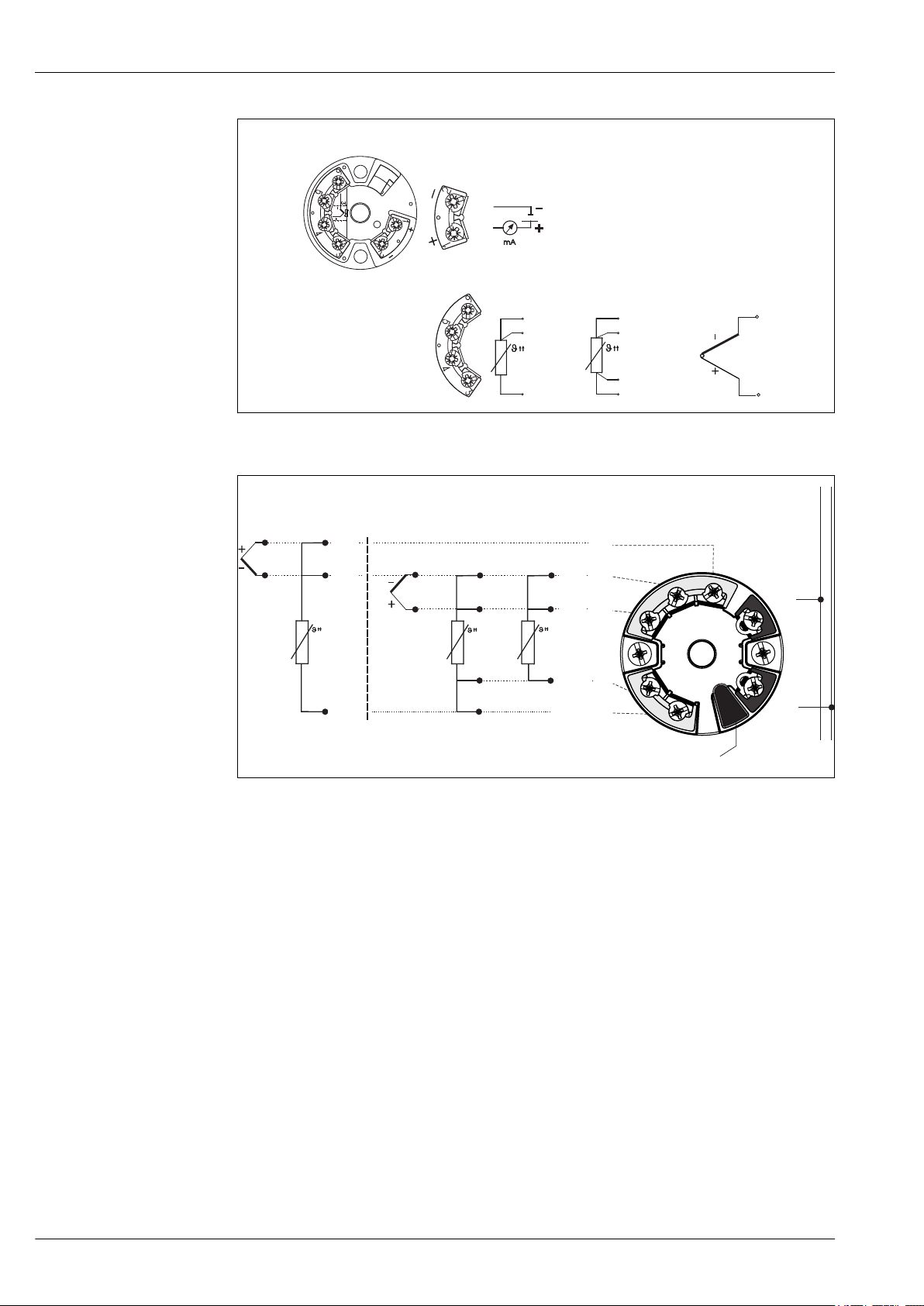
Wiring diagrams for TC and RTD connection
Page 8
iTHERM MultiSens Bundle TMS31
3
5
6
RTD
3
4
5
6
RTD
1
2
TC
6
4
3-wire
4-wire
Power supply
head transmitter and
analog output 4 to 20 mA,
or bus connection
(red) (red)
(red) (red)
(white) (white)
(white)
-
+
+
1
-
2
7
6
5
4
3
1
2
7
6
5
4
3
Sensor input 2
Sensor input 1
RTD 4- and 3-wire:
RTD 3-wire:
Bus connection
and supply voltage
Display connection
red
white
red red
red
whitewhite
TC
TC
3 Wiring diagram of the single sensor input head transmitters (TMT18x)
A0016712-EN
4 Wiring diagram of the dual sensor input head transmitters (TMT8x)
8 Endress+Hauser
A0016711-EN
Page 9
iTHERM MultiSens Bundle TMS31
1
CHANNEL ERROR
COM/
ERR
1:
2:
3-8: Not Used
Write Lock
Simulate Enable
PWR
2 3 5 6 7 84
Do not open !
CH1
RTD
Ω
TC
mV
CH1...CH8
H
H
H
H
H
S
L
L
L
L
L
L
L
FOUNDATION
Fieldbus
TM
0032
0123456789101
1019876543210
TMT125-XXXXXXXX
Ser.No.:
TAG No.:
Order Code:
TMT125
PTB 05ATEX xxxxX
II 3G EEx nAII T4
II 3G EEx nLIIC T4
II (3)G [EEx nL] IICT4
PTB 05ATEX xxxx
II2 (1G/D)G EEx ia IICT4
II(1) GD [EEx ia ] IIC
-40°C<Ta < 70°C
FISCO according to IECTS 60079-27
DEVICE ID 452B4810CD-...
Avoid electrostatic charge!
inst. per XA056R/09/a3/XX.XX
-
LH
+
#
4-wire
2-wire
3-wire
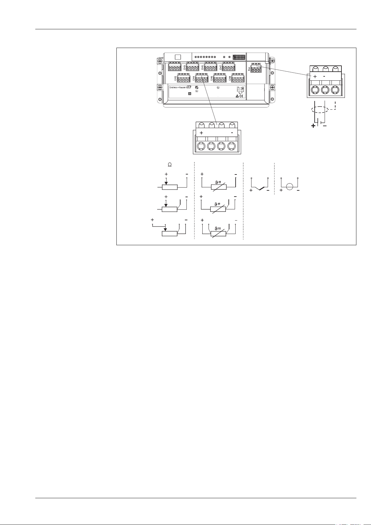
A0006330-EN
5 Wiring diagram of multi-channel transmitter
Endress+Hauser 9
Page 10

Performance characteristics
A
AA
-200 -100 0 100 200 300 400 500 600°C
0.5
1.0
1.5
2.0
B
2.5
3.0
- 0.5
- 1.0
- 1.5
- 2.0
- 2.5
- 3.0
B
A
AA
Max. deviation (°C)
Max. deviation (°C)
iTHERM MultiSens Bundle TMS31
Accuracy
RTD resistance thermometer as per IEC 60751
Class Max. tolerances (°C) Characteristics
Cl. AA, former 1/3
± (0.1 + 0.0017 · |t|
1)
)
Cl. B
Cl. A ± (0.15 + 0.002 · |t|
Cl. B ± (0.3 + 0.005 · |t|
1)
)
1)
)
Temperature ranges for compliance with the
tolerance classes
Wire wound
sensor (WW):
Thin-film version
Cl. A Cl. AA
–100 to +450 °C –50 to +250 °C
Cl. A Cl. AA
(TF):
Standard –30 to +300 °C 0 to +150 °C
1) |t| = absolute value °C
In order to obtain the maximum tolerances in °F, the results in °C must be multiplied by a factor
of 1.8.
Permissible deviation limits of thermoelectric voltages from the standard characteristic for
thermocouples as per IEC 60584 or ASTM E230/ANSI MC96.1:
Standard Type Standard tolerance Special tolerance
IEC 60584 Class Deviation Class Deviation
J (Fe-CuNi) 2 ±2.5 °C (–40 to 333 °C)
±0.0075 |t|
K (NiCr-NiAl) 2 ±2.5 °C (–40 to 333 °C)
±0.0075 |t|
1) |t| = absolute value °C
Standard Type Standard tolerance Special tolerance
ASTM E230/ANSI
MC96.1
J (Fe-CuNi) ±2.2 K or ±0.0075 |t|
K (NiCrNiAl)
1) |t| = absolute value °C
Deviation, the larger respective value applies
±2.2 K or ±0.02 |t|
±2.2 K or ±0.0075 |t|
1)
(333 to 750 °C)
1)
(333 to 1 200 °C)
1)
(0 to 760 °C) ±1.1 K or ±0.004 |t|
1)
(–200 to 0 °C)
1)
(0 to 1 260 °C)
1 ±1.5 °C (–40 to 375 °C)
±0.004 |t|
1 ±1.5 °C (–40 to 375 °C)
±0.004 |t|
1)
(375 to 750 °C)
1)
(375 to 1 000 °C)
1)
(0 to 760 °C)
±1.1 K or ±0.004 |t|
1)
(0 to 1 260 °C)
A0008588-EN
10 Endress+Hauser
Page 11

iTHERM MultiSens Bundle TMS31
Influence of ambient temperature
Response time
Depends on the head transmitter used. For details, see the Technical Information.
Response time for the sensor assembly without transmitter. It refers to inserts in direct contact
with process.
RTD
Calculated at an ambient temperature of approx. 23 °C by immersing the insert in running water (0.4
m/s flow rate, 10 K excess temperature):
Insert diameter Response time
Mineral-insulated cable, 3 mm (0.12 in) t
RTD insert StrongSens, 6 mm (¹⁄₄ in) t
50
t
90
50
t
90
2 s
5 s
< 3.5 s
< 10 s
Thermocouple (TC)
Calculated at an ambient temperature of approx. 23 °C by immersing the insert in running water (0.4
m/s flow rate, 10 K excess temperature):
Insert diameter Response time
Grounded thermocouple:
3 mm (0.12 in), 2 mm (0.08 in)
Ungrounded thermocouple:
3 mm (0.12 in), 2 mm (0.08 in)
t
50
t
90
t
50
t
90
0.8 s
2 s
1 s
2.5 s
Shock and vibration resistance
Calibration
• RTD: 3G / 10 to 500 Hz according to IEC 60751
• RTD iTHERM StrongSens Pt100 (TF, vibration resistant): Up to 60G
• TC: 4G / 2 to 150 Hz according to IEC 60068-2-6
Calibration is a service that can be performed on each individual insert, either in order phase, or after
multipoint installation.
When calibration shall be performed once the multipoint is installed, please contact the
Endress+Hauser service to get full support. Together with the Endress +Hauser service any
further activity can be organised to achieve the calibration of the target sensor. In any case it is
forbidden to unscrew any threaded component on the process connection under operating
conditions = running process.
Calibration involves comparing the measured values of the sensing elements of the multipoint
inserts (DUT device under test) with those of a more precise calibration standard using a defined and
reproducible measurement method. The aim is to determine the deviation of the DUT measured
values from the true value of the measured variable.
Two different methods are used for the inserts:
• Calibration at fixed-point temperatures, e.g. at the freezing point of water at 0 °C (32 °F).
• Calibration compared against a precise reference thermometer.
Evaluation of inserts
If a calibration with an acceptable uncertainty of measurement and transferable measurement
results is not possible, Endress+Hauser offers an insert evaluation measurement service, if
technically feasible.
Endress+Hauser 11
Page 12
Installation
2
1
iTHERM MultiSens Bundle TMS31
Mounting location
Orientation
The installation location must meet the requirements listed in this documentation, such as ambient
temperature, protection classification, climatic class, etc.. Care should be taken when checking the
sizes of possible existing support frames or brackets welded on the wall of the storage tank or of any
other existing frame in the installation area.
The rope multipoint thermometer can be installed in vertical position. The rooftop of the storage
tank or silo can be either horizontal or oblique, the rope-joint will automatically adjust its inclination
to keep the rope always straight in vertical position.
Installation instructions
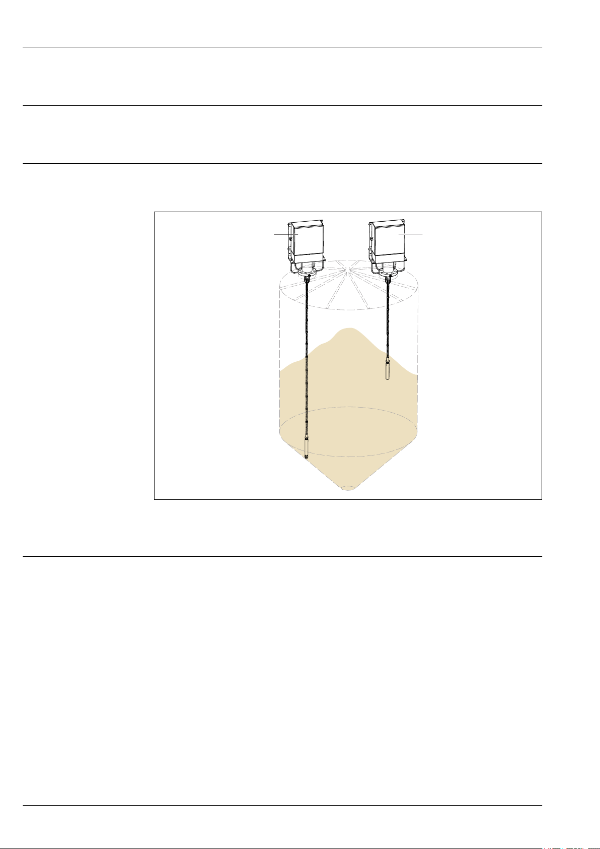
A0038297
6 Installation examples
1 TMS 31 hooked to anchored to the bottom
2 TMS 31 with free hanging weight
The rope multipoint thermometer is designed to be installed with a flanged process connection into a
storage tank, silo or similar environment. All parts and components have to be handled with care.
During the installation phase, lifting and inserting the device through the preset nozzle, the
following must be avoided:
• Misalignment with the nozzle axis.
• Any load on the welded or threaded parts due to the action of the weight of the device.
• Deformation or crushing of the threaded components, bolts, nuts, cable glands and compression
fittings.
• Friction between the temperature probes and the internals of the storage tank.
• Avoid any excessive twisting of the rope around its axis which may cause damage to the rope or to
the temperature probes.
Ensure that:
• In case of hanging weight design, the same is not touching the bottom of the storage tank.
• In case of swage eye design, the rope is correctly tensioned thanks to proper hooks or similar
systems (end users responsibility).
12 Endress+Hauser
Page 13
iTHERM MultiSens Bundle TMS31
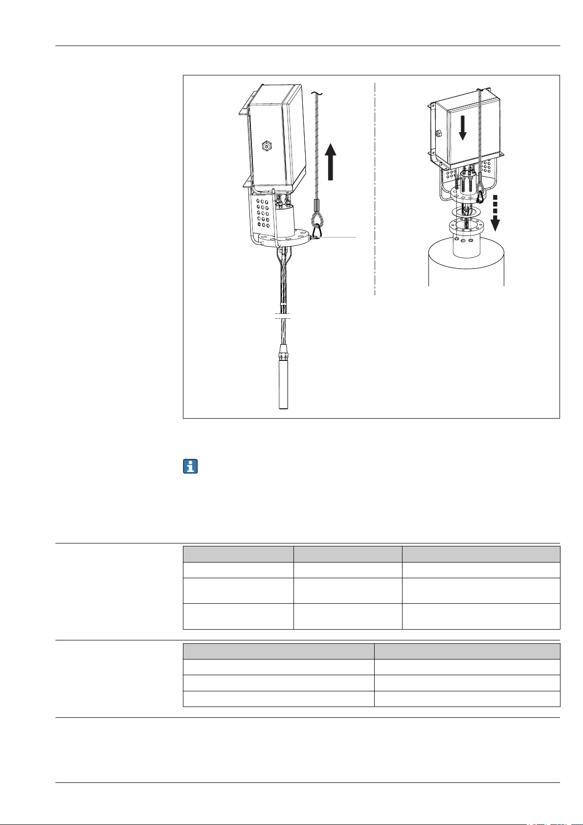
1
Ambient temperature range
Storage temperature
7 Multipoint thermometer installation in a storage tank nozzle via flange process connection.
During installation the whole thermometer must only be lifted and moved by using ropes and
the eyebolt of the flange (1) in order to keep the device as straight as possible.
Environment
Junction box Non-hazardous area Hazardous area
Without mounted transmitter –50 to +85 °C (–58 to +185 °F) –50 to +60 °C (–58 to +140 °F)
With mounted head
transmitter
With mounted multi-channel
transmitter
Junction box
With head transmitter –50 to +95 °C (–58 to +203 °F)
With multi-channel transmitter –40 to +80 °C (–40 to +176 °F)
With DIN rail transmitter –40 to +95 °C (–40 to +203 °F)
–40 to +85 °C (–40 to +185 °F) Depends on the respective hazardous area
approval. Details see Ex documentation.
–40 to +85 °C (–40 to +185 °F) –40 to +70 °C (–40 to +158 °F)
A0038298
Humidity
Condensation according to IEC 60068-2-33:
• Head transmitter: Permitted
• DIN rail transmitter: Not permitted
Maximum relative humidity: 95% according to IEC 60068-2-30
Endress+Hauser 13
Page 14

iTHERM MultiSens Bundle TMS31
Climate class
Degree of protection
Electromagnetic compatibility (EMC)
Determined when the following components are installed into the junction box:
• Head transmitter: Class C1 according to EN 60654-1
• Multi-channel transmitter: Tested as per IEC 60068-2-30, meets the requirements regarding class
C1-C3 in accordance with IEC 60721-4-3
• Terminal blocks: Class B2 according to EN 60654-1
• Specification for conduit: IP68
• Specification for the junction box: IP66/67
Depending on the head transmitter used. For detailed information see the related Technical
Information, listed at the end of this document.
Process
Agriculture:
The loading and unloading forces and the connection to the tank or silo are the minimum input
parameters for the selection of the right product configuration. If special design is requested,
additional data such as type of stored material, geometry of the container and type of connection
have to be considered as mandatory for the whole product definition.
Petrolchemical, Oil & Gas:
The process temperature and process pressure are the minimum input parameters for the selection
of the right product configuration. If special product features are requested, additional data such as
process fluid type, phases, concentration, viscosity, stream and turbulences, corrosion rate have to be
considered as mandatory for the whole product definition.
Process temperature range
Process pressure range
Design, dimensions
–10 to +100 °C (+14 to +212 °F).
Up to 40 bar (580.1 psi)
Anyhow, the maximum required process pressure has to be combined with the maximum
design process temperature. Process connections like compression fittings and flanges with
their specific ratings define the maximum operating conditions. Endress+Hauser experts can
support the customer on any related questions.
Process application examples:
• Storage of Hydrocarbons
• LPG/LNG
• Liquid Nitrogen
• Organic bulk material storage (cereals, crop, …)
• Grain silos
• Bulk liquid storage tank
• Beverage processing
Mechanical construction
The overall rope assembly is made of different parts. The rope joint ensures sufficient degree of
freedom to the rope system allowing movements during filling and emptying operations. This
guarantees low stresses (no extra tensioning) on the rope due to possible lateral force acting on it,
therefore a lateral sag of 30cm per 10m rope length is recommended. The transition between the
inserts and the extension cable is obtained by the usage of compression fittings, ensuring the
declared IP degree protection.
14 Endress+Hauser
Page 15

iTHERM MultiSens Bundle TMS31
I
H
I
C
H
A
B
F
L
MPx
A
A
B
L
MPx
F
MPx
L
B
L
MPx
F
MPx
L
U
U
U
L
MPx
A0038299
8 Design of the modular multipoint thermometer, with tube neck on the left side, frame neck on the middle
or with tube neck design as option on the right side. All dimensions in mm (in)
A, B,CDimensions of the junction box, see following figure
MPx Numbers and distribution of measuring points: MP1, MP2, MP3 etc.
L
Immersion length of sensing elements or thermowells
MPx
I, H Encumbrance of the junction box and support system
F Extension neck length
L Device length
U Immersion length
Extension neck F in mm (in)
Standard 250 (9.84)
Specifically customized extension necks are available on request.
Immersion lengths MPx of sensing elements/thermowells:
Based on customer requirements
Endress+Hauser 15
Page 16
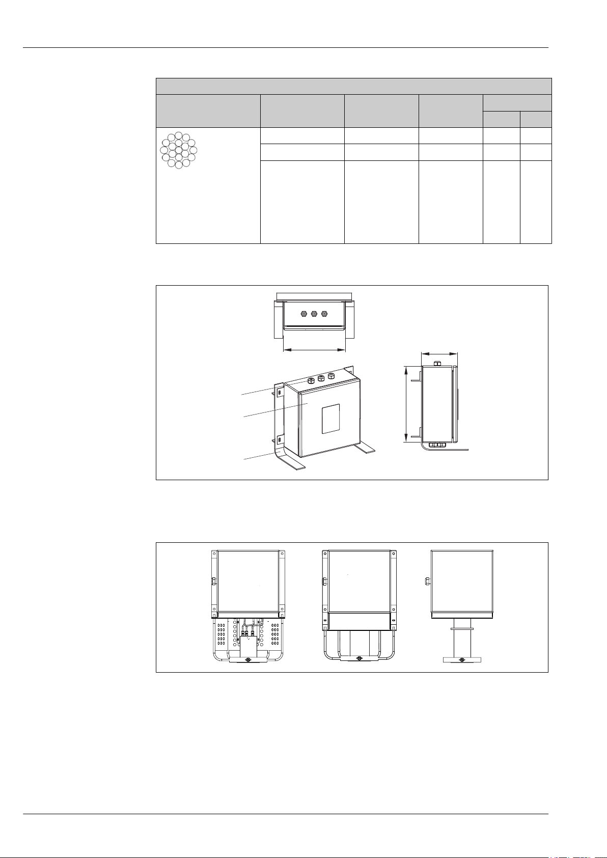
Rope maximum load:
1
2
3
A
B
C
Rope
Ø mm
6 1x19 0,1786 29,5 3000
8 1x19 0,322 53 5400
10 1x19 0,502 84 8500
A0038300
• Stainless steel AISI 316
• Rope according to EN
10264-4
• Rope grade
1.570 N/mm2
Junction box (directly mounted)
iTHERM MultiSens Bundle TMS31
Construction Weight
kg/m
MBL
kN kg
A0028118
1 Cable glands
2 Junction box
3 Frame
A0038301
9 Open design on the left side, with cover design in the middle and tube neck design on the right side
16 Endress+Hauser
Page 17

iTHERM MultiSens Bundle TMS31
A
10 Remote junction box design
A0038302
The junction box is suited for chemical agents environments. Sea water corrosion resistance and
extreme temperature variation stability is guaranteed. Ex-e Ex-i terminals can be installed.
Possible junction box dimensions (A x B x C) in mm (in):
A B C
Stainless Steel Min. 170 (6.7) 170 (6.7) 130 (5.1)
Max. 500 (19.7) 500 (19.7) 240 (9.5)
Aluminium Min. 100 (3.9) 150 (5.9) 80 (3.2)
Max. 330 (13) 500 (19.7) 180 (7.1)
Type of specification Junction box Cable glands
Material AISI 316/Aluminium NiCr Plated brass
AISI 316 / 316L
Ingress protection (IP) IP66/67 IP66
Ambient temperature range –50 to +60 °C
(–58 to +140 °F)
Approvals ATEX, FM, UL, CSA approval
for use in hazardous area
IEC
Marking • ATEX II 2 GD Ex e IIC /Ex ia
Ga IIC Ex tb IIIC Db
T6/T5/T4
• UL913 Class I, Division 1
Groups B, C, D T6/T5/T4
• FM3610 Class I, Division 1
Groups B, C, D T6/T5/T4
• CSA C22.2 No. 157 Class 1,
Cover Hinged -
Maximum sealing diameter - 6 to 12 mm (0.24 to 0.47 in)
Division 1 Groups B, C, D
T6/T5/T4
–52 to +110 °C (–61.1 to +140 °F)
-
-
Endress+Hauser 17
Page 18

iTHERM MultiSens Bundle TMS31
On board Remote
Type of protection Intrinsically safe
and increased
safety
Flameproof With supporting
Field display
Power: 100-240 Vac, 50-60 Hz, 25 VA, 0.375 A max
Certification: ATEX II 2 G D Ex ‘d’ IIC T6, IP 66
Enviroment: Hazardous Area Zone 1
Operating temperture: -20 °C to +55 °C
Storage temperture: -40 °C to +85 °C
Enclosure: Aluminium alloy Painted RAL 7035 grey epoxy
IP rating: IP66
Entries: M20 threaded entries (quantity 5 off)
External dimensions: 300 x 230 x 155 mm
Fixings: To suit M12 bolts, four positions
Weight: 7.5 kg
No. of host ports: 4 Ports
Interfaces supported: RS-232, RS-422/485, Modbus RTU HART®
• With frame
• Tube neck
frame
Flexible conduit
A0038303
Neck extension
The neck extension ensures the connection between the flange and the junction box. The design has
been developed to ensure several mounting layouts to deal with possible obstacles and constraints
that can be met in any plant such as the storage tank infrastructure (step ways, loading structures,
stairs, etc.) and an eventual thermal insulation. The neck extension design allows easy access for
monitoring extension cables. It guarantees a high stiffness connection for the junction box and
vibration loads. No closed volumes are present in the neck extension (not for tube neck design). This
avoids the accumulation of waste and potentially dangerous fluids coming from the environment
that can damage the instrumentation allowing continuous ventilation.
18 Endress+Hauser
Page 19

iTHERM MultiSens Bundle TMS31
Inserts
Thermocouple
Diameter in mm (in) Type Standard Hot junction type Sheath material
3 (0.12)
RTD
Diameter in mm (in) Type Standard Sheath material
3 (0.12)
6 (¹⁄₄)
Different insert types are available. For any different requirement that is not described here,
please contact the Endress+Hauser sales department.
1x type K
2x type K
1x type J
2x type J
IEC 60584 /ASTM E230 Grounded/Ungrounded AISI 316L
1x Pt100 WW
2x Pt100 WW
1x Pt100 TF
2x Pt100 TF
IEC 60751 AISI 316L
Weight
Materials
The weight can vary depending on the configuration: Dimension and content of the junction box,
neck length, dimensions of process connection, the number of inserts and the weight of the rope
end. The approximate weight of a typically configured multipoint rope (number of inserts = 12,
flange size = 3", medium size junction box) = 55 kg (121 lb)
It refers to insert sheath, neck extension, junction box and all wetted parts.
The temperatures for continuous operation specified in the following table are only intended as
reference values for use of the various materials in air and without any significant compressive load.
The maximum operation temperatures are reduced considerably in some cases where abnormal
conditions such as high mechanical load occur or in aggressive media.
Material
name
AISI
316/1.4401
AISI 316L/
1.4404
1.4435
Alloy600/
2.4816
Short form Recommended
max.
temperature for
continuous use
in air
X5CrNiMo 17-12-2 650 °C (1 202 °F) • Austenitic, stainless steel
X2CrNiMo17-12-2
X2CrNiMo18-14-3
NiCr15Fe 1 100 °C
650 °C (1 202 °F) • Austenitic, stainless steel
(2 012 °F)
Properties
• High corrosion resistance in general
• Particularly high corrosion resistance in chlorinebased and acidic, non-oxidizing atmospheres
through the addition of molybdenum (e.g.
phosphoric and sulfuric acids, acetic and tartaric
acids with a low concentration)
• High corrosion resistance in general
• Particularly high corrosion resistance in chlorinebased and acidic, non-oxidizing atmospheres
through the addition of molybdenum (e.g.
phosphoric and sulfuric acids, acetic and tartaric
acids with a low concentration)
• Increased resistance to intergranular corrosion
and pitting
• Compared to 1.4404, 1.4435 has even higher
corrosion resistance and a lower delta ferrite
content
• A nickel/chromium alloy with very good
resistance to aggressive, oxidizing and reducing
atmospheres, even at high temperatures
• Resistance to corrosion caused by chlorine gases
and chlorinated media as well as many oxidizing
mineral and organic acids, sea water etc.
• Corrosion from ultrapure water
• Not to be used in sulfur-containing atmospheres
Endress+Hauser 19
Page 20

iTHERM MultiSens Bundle TMS31
Material
name
AISI
304/1.4301
AISI 304L/
1.4307
AISI 316Ti/
1.4571
AISI
321/1.4541
AISI
347/1.4550
Short form Recommended
max.
temperature for
continuous use
in air
X5CrNi18-10 850 °C (1 562 °F) • Austenitic, stainless steel
X2CrNi18-9 850 °C (1 562 °F) • Good welding properties
X6CrNiMoTi17-12-2 700 °C (1 292 °F) • Addition of titanium means increased resistance
X6CrNiTi18-10 815 °C (1 499 °F) • Austenitic stainless steel
X6CrNiNb10-10 800 °C (1 472 °F) • Austenitic stainless steel
Properties
• Well usable in water and lowly pollute waste
water
• Only at relatively low temperatures resistant to
organic acids, saline solutions, sulphates,
alkaline solutions, etc.
• Impervious to intergranular corrosion
• High ductility, excellent drawing, forming, and
spinning properties
to intergranular corrosion even after welding
• Broad range of uses in the chemical,
petrochemical and oil industries as well as in coal
chemistry
• Can only be polished to a limited extent, titanium
streaks can form
• High resistance to intergranular corrosion even
after welding
• Good welding characteristics, suitable to all
standard welding methods
• It is used in many sectors of the chemical
industry, petrochemical, and pressurized vessels
• Good resistance to a wide variety of
environments in the chemical, textile, oilrefining, dairy and food industries
• Added niobium makes this steel impervious to
intergranular corrosion
• Good weldability
• Main applications are furnace fire walls, pressure
vessels, welded structures, turbine blades
Process connection
Standard process connection flanges are designed according to the following standards:
Standard
ASME 1½”, 2”, 3”, 4” 150#, 300# AISI 316, 316L, 316Ti
EN DN40, DN50, DN80, DN100 PN16, PN40
1) Flanges according to GOST standard are available on request.
1)
Size Rating Material
Operability
For details of operability, see the Technical Information of the Endress+Hauser temperature
transmitters or the manuals of the related operating software.→ 27
20 Endress+Hauser
Page 21

iTHERM MultiSens Bundle TMS31
Certificates and approvals
CE Mark
Hazardous area approvals
Certification HART
Certification FOUNDATION Fieldbus
Certification PROFIBUS® PA
The complete assembly is provided with individual components CE marked, to ensure safe use in
hazardous areas and pressurized environments.
The Ex approval applies to individual components like junction box, cable glands, terminals. For
further details on the available Ex versions (ATEX, CSA, FM, IEC-EX, UL, NEPSI, EAC-EX), please
contact your nearest Endress+Hauser sales organization. All relevant data for hazardous areas can
be found in separate Ex documentation.
The HART® temperature transmitter is registered by the FieldComm Group. The device meets the
requirements of the HART® Communication Protocol Specifications.
The FOUNDATION Fieldbus™ temperature transmitter has successfully passed all test procedures
and is certified and registered by the Fieldbus Foundation. The device thus meets all the
requirements of the following specification:
• Certified according to FOUNDATION Fieldbus™ specification
• FOUNDATION Fieldbus™ H1
• Interoperability Test Kit (ITK), up to date revision status (device certification no. available on
request): the device can also be operated with certified devices of other manufacturers
• Physical layer conformance test of the FOUNDATION Fieldbus™
The PROFIBUS® PA temperature transmitter is certified and registered by the PNO (PROFIBUS®
Nutzerorganisation e. V.), PROFIBUS user organization. The device meets all the requirements of the
following specifications:
• Certified according to FOUNDATION Fieldbus™ specification
• Certified in accordance with PROFIBUS® PA Profile (the up to date profile version is available on
request)
• The device can also be operated with certified devices of other manufacturers (interoperability)
Other standards and guidelines
Material certification
Test report and calibration
• EN 60079: ATEX certification for hazardous areas
• IEC 60529: Degree of protection of housing (IP code)
• IEC 60584 and ASTM E230/ANSI MC96.1: Thermocouples
The material certificate 3.1 (according to EN 10204) can be requested separately. The certificate
includes a declaration related to the materials used to produce the thermometer. It guarantees the
traceability of the materials through the identification number of the rope multipoint thermometer.
The "Factory calibration" is carried out according to an internal procedure in a laboratory of Endress
+Hauser accredited by the European Accreditation Organization (EA) to ISO/IEC 17025. A
calibration which is performed according to EA guidelines (SIT/Accredia) or (DKD/DAkkS) may be
requested separately. The calibration is performed on the inserts of the multipoint.
Endress+Hauser 21
Page 22

iTHERM MultiSens Bundle TMS31
Ordering information
Overview of the scope of delivery see the configuration table below.
Detailed ordering information is available from your Endress+Hauser Sales Center:
www.addresses.endress.com
Process connection: Flange
Standard • ASME B16.5
• EN 1092-1
Others on request
Material • 316
• 316L
• 316TI
Others on request
Face RF, Type A, B1
Others on request
Size • 1½", 2", 3", 4"
• DN40, DN50, DN80, DN100
Others on request
________
________
The values reported in the table below are indicative, based on calculations for nozzles with
standard dimensions. So the maximum number of measurement points can differ from the
maximum number of the configuration table. It depends on the dimensions of the nozzle used
on location.
Flange size (considering a schedule 40 nozzle) Maximum number of inserts
Inserts diameter
3 mm (0.12 in) 6 mm (0.24 in)
1½" 10 4
2" 15 8
3" 20 20
4" 20 20
Insert, sensor
Measuring principle • Thermocouple (TC)
• Resistance Temperature Detection (RTD)
Type TC: J, K
RTD: Pt100
Design • TC: Single, duplex
• RTD: 3-wire, 4-wire, 2x3-wire
Execution • TC: Grounded, Ungrounded
• RTD: Wire wound (WW); Thin film (TF)
Sheath material 316L ________
Approvals • Intrinsic safety
• Non hazardous
________
________
22 Endress+Hauser
Page 23

iTHERM MultiSens Bundle TMS31
Insert, sensor
Insert, sensor • 3 mm (0.12 in)
Standard/Class IEC/Class 1
Measurement point distribution
Positioning • Equi spaced
Number 2, 4, 6, 8, 10, 12 ... 20
• 6 mm (0.24 in)
Others on request
ASTM/Class special
IEC/Class 2
ASTM/Class standard
IEC/Class A
IEC/Class AA
Others on request
• Customized
1)
________
Insertion length TAG (description) (L
MP
MP
MP
MP
MP
MP
MP
1
2
3
4
5
6
x
_________________________________________ __________
_________________________________________ __________
_________________________________________ __________
_________________________________________ __________
_________________________________________ __________
_________________________________________ __________
_________________________________________ __________
1) Different numbers/configurations are available on request
Junction box (head)
Material • Stainless steel (standard)
• Aluminum (to be specified)
Others on request
Electrical connection Terminal block wiring:
• Terminal block - standard/number
• Terminal block - compensated/number
• Terminal block - spare/number
Transmitter wiring:
• HART protocol, e. g.: TMT182, TMT82
• PROFIBUS PA protocol, e. g.: TMT84
• FOUNDATION Fieldbus protocol, e. g.: TMT85,
TMT125 (multi-channel transmitter)
• Quantity
Approvals Ex e / Ex ia / Ex d
Others on request
Cable entries (process side) Single or multiple,
type: M20, NPT ½", Quantity
Others on request
Cable entries (wiring side) Single or multiple,
type: M20, M25, NPT ½", NPT 1" / Quantity
Others on request
) in mm (in)
MPx
/ _____
/ _____
/ _____
_______
_______
_______ / _______
_______ / _______
_______ / _______
_______ / _______
Endress+Hauser 23
Page 24

Junction Box supporting frame
• Remote with protecting hose
• Remote without protecting hose
• Directly mounted
Extension neck
Length F in mm (in) 250 mm (9.84 in)
Or as specified
TAG
Device information Refer to customer specification
As specified
Measuring point
information
Refer to customer specification
Location, as specified:
• Tagging (TAG), on extension wires insert
• Tagging (TAG), RFID
• Tagging (TAG), on device
• Tagging (TAG), by customer
• Tagging (TAG), on transmitter
Special version, to be specified
iTHERM MultiSens Bundle TMS31
________
(table)
Additional requests
Extension wire length, only
for remote head
Extension wires sheath
material
Test, Certificate, Declaration
Inspection certificate 3.1, EN10204 (material certificate wetted parts)
Inspection certificate 3.1, short form, EN10204, (material certificate wetted parts)
PMI test, Endress+Hauser procedure, (wetted parts), test report
Final assembly functional test, test report
Final inspection report
2D dimensional drawing
Welding book (including welding map)
Radiographic inspection certificate on hot junctions/tips for sensors
Manufacturer declaration
Dye penetrant test, test report
Inspection test report (Sensor/TMT), inspection certificate
Quality control plan
Specification in mm:
• PVC
• MFA
Others on request
________
24 Endress+Hauser
Page 25

iTHERM MultiSens Bundle TMS31
Accessories
Various accessories, which can be ordered with the device or subsequently from Endress+Hauser, are
available for the device. Detailed information on the order code in question is available from your
local Endress+Hauser sales center.
Device-specific accessories
Accessories Description
Anchor weight
Ogives
The installation of the anchor weight ensures a straight
vertical position of the rope, please make sure to have
enough space for a correct weight positioning inside the
storage system. The dimensions will be established
during the order development according to the rope
multipoint dimension.
• Left side - Removable/Replaceable
• Right side - Fixed
A0038304
Ogives are integrated in the multipoint rope, they provide
a correct positioning of the probe thermoelement along
the rope length and maintain them in position under
working condition.
Toggle joint terminal
A0038305
Toggle joint connection between rope and flange to allow
reciprocal rotation.
A0038306
Endress+Hauser 25
Page 26

iTHERM MultiSens Bundle TMS31
Communication-specific accessories
Configuration kit TXU10 Configuration kit for PC-programmable transmitter with setup software and
interface cable for PC with USB port
Order code: TXU10-xx
Commubox FXA195
HART
Commubox FXA291 Connects Endress+Hauser field devices with a CDI interface (= Endress+Hauser
HART Loop Converter
HMX50
Wireless HART adapter
SWA70
Fieldgate FXA320 Gateway for the remote monitoring of connected 4-20 mA measuring devices via a
For intrinsically safe HART communication with FieldCare via the USB interface.
For details, see "Technical Information" TI00404F
Common Data Interface) and the USB port of a computer or laptop.
For details, see "Technical Information" TI00405C
Is used to evaluate and convert dynamic HART process variables to analog current
signals or limit values.
For details, see "Technical Information" TI00429F and Operating Instructions
BA00371F
Is used for the wireless connection of field devices.
The WirelessHART adapter can be easily integrated into field devices and existing
infrastructures, offers data protection and transmission safety and can be operated
in parallel with other wireless networks with minimum cabling complexity.
For details, see Operating Instructions BA061S
Web browser.
For details, see "Technical Information" TI00025S and Operating Instructions
BA00053S
Service-specific accessories
Fieldgate FXA520 Gateway for the remote diagnostics and remote configuration of connected HART
measuring devices via a Web browser.
For details, see "Technical Information" TI00025S and Operating Instructions
BA00051S
Field Xpert SFX100 Compact, flexible and robust industry handheld terminal for remote configuration
and for obtaining measured values via the HART current output (4-20 mA).
For details, see Operating Instructions BA00060S
Accessories Description
Applicator Software for selecting and sizing Endress+Hauser measuring devices:
• Calculation of all the necessary data for identifying the optimum measuring
device: e.g. pressure loss, accuracy or process connections.
• Graphic illustration of the calculation results
Administration, documentation and access to all project-related data and
parameters over the entire life cycle of a project.
Applicator is available:
• Via the Internet: https://wapps.endress.com/applicator
• On CD-ROM for local PC installation.
W@M Life cycle management for your plant
W@M supports you with a wide range of software applications over the entire
process: from planning and procurement, to the installation, commissioning and
operation of the measuring devices. All the relevant device information, such as
the device status, spare parts and device-specific documentation, is available for
every device over the entire life cycle.
The application already contains the data of your Endress+Hauser device. Endress
+Hauser also takes care of maintaining and updating the data records.
W@M is available:
• Via the Internet: www.endress.com/lifecyclemanagement
• On CD-ROM for local PC installation.
26 Endress+Hauser
Page 27

iTHERM MultiSens Bundle TMS31
FieldCare FDT-based plant asset management tool from Endress+Hauser.
Documentation
• Operating manuals iTEMP temperature transmitters:
• Technical Information of inserts:
• Technical Information application example:
It can configure all smart field units in your system and helps you manage them. By
using the status information, it is also a simple but effective way of checking their
status and condition.
For details, see Operating Instructions BA00027S and BA00059S
– TMT180, PC-programmable, single-channel, Pt100 (KA00118R/09/a3)
– TMT181, PC programmable, single-channel, RTD, TC, Ω, mV (KA141R/09/a3)
– HART® TMT182, single-channel, RTD, TC, Ω, mV (KA142R/09/c4)
– HART® TMT82, two-channel, RTD, TC, Ω, mV (BA01028T/09/en)
– PROFIBUS® PA TMT84, two-channel, RTD, TC, Ω, mV (BA00257R/09/en)
– FOUNDATION FieldbusTM TMT85, two-channel, RTD, TC, Ω, mV (BA00251R/09/en)
– FOUNDATION FieldbusTM TMT125, 8-channel, RTD, TC, Ω, mV (BA00240R/09/en)
– Safety requirements: DIN EN 61010-1:2011-07
– EMC requirements : DIN EN 61326-1:2013-07
– RSG45 DIN RAIL
– TMT162
– TMT142
– Field Display (FD188)
– Resistance thermometer insert Omnigrad T TST310 (TI00085T/09/en)
– Thermocouple insert Omnigrad T TSC310 (TI00255t/09/en)
– RN221N active barrier, for supplying loop-powered 2-wire transmitters (TI073R/09/en)
– HAW562 surge arresters, (TI01012K/09/en)
Endress+Hauser 27
Page 28

www.addresses.endress.com
 Loading...