

Page 1
TI01298T/09/EN/02.18
71426007
2018-12-24
Products
Solutions Services
Technical Information
iTHERM MultiSens Slim
TMS21
Low invasive direct contact multipoint
thermometer
Application
• Easy-to-use device with flexible design, ready to be installed in case of direct
contact and fast response time measurements
• Specifically designed for light chemical processes
• Measuring range:
Thermocouple (TC): –270 to 920 °C (–454 to 1 688 °F)
• Static pressure range: Up to 90 bar (1 305 psi). Specific maximum process pressure
achievable depending on process type and temperature
Your benefits
• High degree of flexibility thanks to a wide variety of options for an easy product
configuration selection and process integration
• High precision temperature profile detection due to an high number of measuring
points - up to 59 points
• Easy process monitoring thanks to low invasiveness and high installation flexibility
• Fast response time
• Compliance to several national and international standards, such as IEC60584,
ASTM E230 and IEC 60751
• Wide range of accessories for the best process integration and monitoring as well
as for protection against mechanical shocks and environmental conditions
• Adjustable immersion length to reach the exact measuring point location
Page 2

Table of contents
iTHERM MultiSens Slim TMS21
Function and system design ................... 3
Measuring principle ............................ 3
Measuring system ............................. 3
Equipment architecture ......................... 4
Input ..................................... 5
Measured variable ............................. 5
Output ................................... 6
Output signal ................................ 6
Family of temperature transmitters ................. 6
Wiring ................................... 7
Wiring diagrams .............................. 7
Performance characteristics ................... 8
Accuracy ................................... 8
Response time ............................... 8
Additional tests (on request) ...................... 9
Calibration .................................. 9
Installation ................................ 9
Mounting location ............................. 9
Orientation ................................ 10
Installation instructions ........................ 10
Final assembly functional test, temperature profile test
report .................................... 17
Final inspection report ......................... 17
Ordering information ....................... 19
Accessories ............................... 21
Device-specific accessories ...................... 21
Communication-specific accessories ................ 22
Service-specific accessories ...................... 23
Documentation ............................ 24
Environment .............................. 11
Ambient temperature range ..................... 11
Storage temperature .......................... 11
Humidity .................................. 11
Degree of protection .......................... 11
Electromagnetic compatibility (EMC) ............... 11
Process .................................. 11
Process temperature range ...................... 11
Process pressure range ......................... 12
Mechanical construction .................... 12
Design, dimensions ........................... 12
Weight ................................... 14
Materials of insert sheath, thermowell, main bushing and
all wetted parts .............................. 14
Process connection ........................... 16
Operability ............................... 16
Certificates and approvals ................... 17
CE Mark .................................. 17
Hazardous area approvals ....................... 17
Certification HART ........................... 17
Certification FOUNDATION Fieldbus ................ 17
Certification PROFIBUS® PA ..................... 17
Other standards and guidelines ................... 17
Material certification .......................... 17
Test report and calibration ...................... 17
2 Endress+Hauser
Page 3

iTHERM MultiSens Slim TMS21
Function and system design
Measuring principle Thermocouples (TC)
Thermocouples are comparatively simple, robust temperature sensors which use the Seebeck effect
for temperature measurement: if two electrical conductors made of different materials are connected
at a point, a weak electrical voltage can be measured between the two open conductor ends if the
conductors are subjected to a thermal gradient. This voltage is called thermoelectric voltage or
electromotive force (emf.). Its magnitude depends on the type of conducting materials and the
temperature difference between the "measuring point" (the junction of the two conductors) and the
"cold junction" (the open conductor ends). Accordingly, thermocouples primarily only measure
differences in temperature. The absolute temperature at the measuring point can be determined
from these if the associated temperature at the cold junction is known or is measured separately and
compensated for. The material combinations and associated thermoelectric voltage/temperature
characteristics of the most common types of thermocouple are standardized in the IEC 60584 and
ASTM E230/ANSI MC96.1 standards.
Measuring system
Endress+Hauser offers a complete portfolio of optimized components for the temperature measuring
point – everything you need for the seamless integration of the measuring point into the overall
facility.
This includes:
• Power supply unit/active barrier
• Configuration units
• Overvoltage protection
For more information, see the brochure 'System Components - Solutions for a Complete
Measuring Point' (FA00016K/09)
Endress+Hauser 3
Page 4
iTHERM MultiSens Slim TMS21
HAW56x
1 IN 2
3 OUT4
HAW56x
3 OUT4
1 IN 2
HAW56x
3 OUT4
1 IN 2
HAW56x
3 OUT4
1 IN 2
1
2
3
4
7
5
+
+
-
-
+
+
-
-
+
+
-
-
+
1
-
2
7
6
5
4
3
+
1
-
2
7
6
5
4
3
+
1
-
2
7
6
5
4
3
+
1
-
2
7
6
5
4
3
6
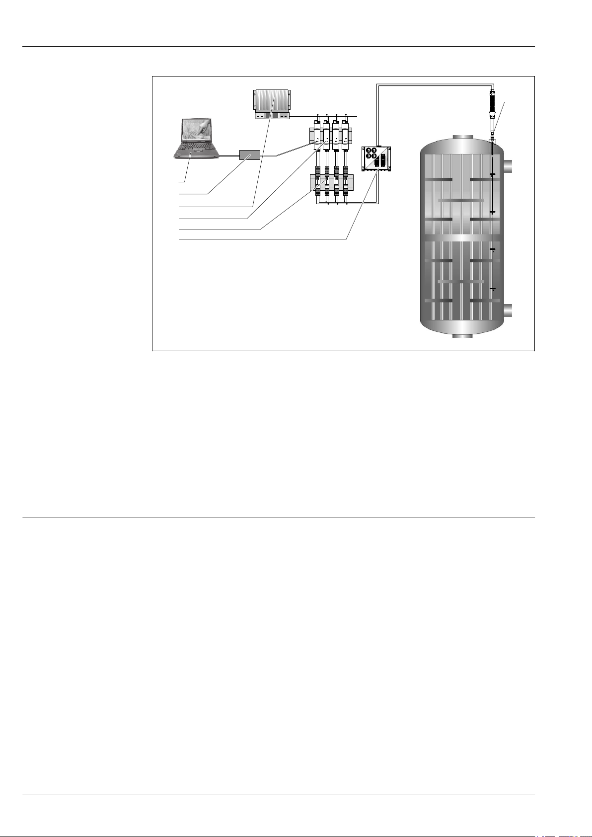
Equipment architecture
1 Application example in a reactor, mounted multipoint thermometer in a locally existing thermowell with
four measurement points and four transmitters or terminal blocks in remote junction box.
1 Device configuration with application software FieldCare
2 Commubox
3 PLC
4 Active barrier RN221N (24 VDC, 30 mA) that has a galvanically isolated output for supplying voltage to loop-
powered transmitters. The universal power supply works with an input supply voltage of 20 to 250 V DC/AC;
50/60 Hz, which means that it can be used in all international power grids.
5 Surge arrester modules HAW562Z for protection of signal lines and components in hazardous areas, e.g.
4 to 20 mA- , PROFIBUS® PA, FOUNDATION Fieldbus™ signal lines. More information on this can be found
in the Technical Information → 24
6 Remote junction box available as an option with built-in transmitter for 4 to 20 mA, PROFIBUS® PA,
FOUNDATION Fieldbus™ signal lines.
7 Mounted multipoint thermometer in a locally existing tube.
The new iTHERM MultiSens Slim has an innovative design able to allow a wide variety of options in
terms of materials selection, sizes and number of measuring points. In addition a portfolio of
selectable accessories (not in contact with the process) individually managed for easy maintenance
and spare part ordering, like adapters and conduits, is available.
It consists of five main sub-assemblies:
• Extension: It consists of a threaded bushing for sealed electrical connections, matched to an
adapter from which flexible conduit containing the extension cables.
• Main bushing and reinforcing sleeve:
• Process connection: The process connection is represented by a compression fitting. When
necessary, an ASME or EN flange is available on request.
Other standards or connection types can be offered on request. The flanges are provided with
welded compression fitting for process tightness.
• Thermowell: with or without reinforcing sleeve
• Insert: Composed of metal sheathed sensing measuring elements (thermocouples), extension
cable and transition bushing. The sensing elements are mounted inside a small diameter pipe
thermowell.
Part of the thermowell can be a flexible hose to guarantee additional bendability into the process
of the sensing probe, to ensure internal routing in the case of misalignment between installation
nozzle and the distribution of measuring points.
• Additional accessories: Components that can be ordered independently from the selected product
configuration, such as junction boxes and transmitters, able to fit with all the already installed
customer devices.
A0033065
4 Endress+Hauser
Page 5
iTHERM MultiSens Slim TMS21
1
2a
3
4
5
2
6
4a
2a
2a
3
4
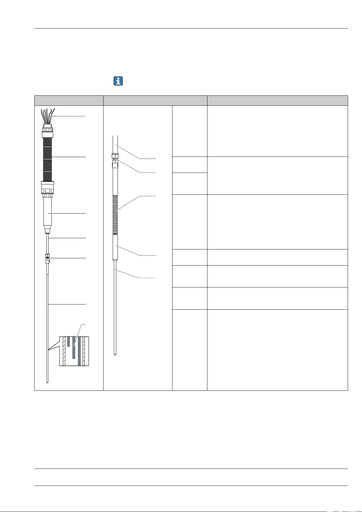
Design Description
In general, the system measures the temperature profile inside the process environment by means of
many sensors, jointed to a suitable process connection which ensures the right tightness levels.
Externally, the extension cables (protected by the conduit) are wired into the junction box, which can
be installed integrated or remote (optional).
Some of the options listed in this document may not be available in your country. Please contact
your local Endress+Hauser representative.
1: Extension Flexible conduit used to protect the extension cables from
environmental agents and phenomena (e.g. abrasion, humidity,
salt conditions).
Material:
• Polyamide
• Other materials on request
IP68 degree is guaranteed through the selected adapters.
2: Main
bushing
2a:
Reinforcing
sleeve
3: Process
connection
4: Thermowell Annealed tube used as protective sheath for sensing elements,
4a: Flexible
thermowell
part
5: Inserts Not replaceable grounded or ungrounded thermocouple inserts
6: Extension
cables
Used to seal and protect electrical junctions and to adjust
immersion length.
High pressure compression fitting for the tightness between the
process and the external environment, for a wide range of process
fluids and different severe combination of temperature and
pressure.
In the case of a flange, the process connection is welded on the
flange (standard). Other versions available on request.
Flange: Different dimensions and sizes to meet specific standards
(e.g. ASME, EN, DIN) and variable process requirements.
inserted into the process
Annealed tube provided of an upper flexible part (corrugated
conduit) to allow to reach different paths into the installation
environment.
with high accuracy measurement performance, long-term stability
and reliability
Not replaceable grounded or ungrounded thermocouple inserts
with high accuracy measurement performance, long-term stability
and reliability
A0033069
A0030865
The modular multipoint thermometer is characterized by the following possible main
configurations:
• Linear configuration
• Flexible configuration
Measured variable
Input
Temperature (temperature linear transmission behavior)
Endress+Hauser 5
Page 6

Output
iTHERM MultiSens Slim TMS21
Output signal
Family of temperature transmitters
Generally, the measured value can be transmitted in one of two ways:
• Directly-wired sensors - sensor measured values forwarded without a transmitter.
• Via all common protocols by selecting an appropriate Endress+Hauser iTEMP temperature
transmitter. All the transmitters listed below are mounted directly in the junction box and wired
with the sensory mechanism.
Thermometers fitted with iTEMP transmitters are an installation-ready complete solution to
improve temperature measurement by significantly increasing accuracy and reliability, when
compared to direct wired sensors, as well as reducing both wiring and maintenance costs.
PC programmable head transmitters
They offer a high degree of flexibility, thereby supporting universal application with low inventory
storage. The iTEMP transmitters can be configured quickly and easily at a PC. Endress+Hauser offers
free configuration software which can be downloaded from the Endress+Hauser Website. More
information can be found in the Technical Information.
HART® programmable head transmitters
The transmitter is a 2-wire device with one or two measuring inputs and one analog output. The
device not only transfers converted signals from resistance thermometers and thermocouples, it also
transfers resistance and voltage signals using HART® communication. It can be installed as an
intrinsically safe apparatus in Zone 1 hazardous areas and is used for instrumentation in the
terminal head (flat face) as per DIN EN 50446. Swift and easy operation, visualization and
maintenance by PC using operating software, Simatic PDM or AMS. For more information, see the
Technical Information.
PROFIBUS® PA head transmitters
Universally programmable head transmitter with PROFIBUS® PA communication. Conversion of
various input signals into digital output signals. High accuracy over the complete ambient
temperature range. Swift and easy operation, visualization and maintenance using a PC directly from
the control panel, e. g. using operating software, Simatic PDM or AMS. For more information, see
the Technical Information.
FOUNDATION Fieldbus™ head transmitters
Universally programmable head transmitter with FOUNDATION Fieldbus™ communication.
Conversion of various input signals into digital output signals. High accuracy over the complete
ambient temperature range. Swift and easy operation, visualization and maintenance using a PC
directly from the control panel, e.g. using operating software such as ControlCare from Endress
+Hauser or NI Configurator from National Instruments. For more information, see the Technical
Information.
Advantages of the iTEMP transmitters:
• Dual or single sensor input (optionally for certain transmitters)
• Unsurpassed reliability, accuracy and long-term stability in critical processes
• Mathematical functions
• Monitoring of the thermometer drift, sensor backup functionality, sensor diagnostic functions
• Sensor-transmitter matching for dual sensor input transmitter, based on Callendar/Van Dusen
coefficients
6 Endress+Hauser
Page 7
iTHERM MultiSens Slim TMS21
1
2
TC
6
4
1
-
+
+
1
-
2
7
6
5
1
2
7
6
5
4
3
2 1
3
4
Wiring
• Electrical connecting cables must be smooth, corrosion resistant, easy to be cleaned and
inspected, robust against mechanical stresses, no-humidity sensitivity.
• Grounding or shielding connections are possible via ground terminals on the junction box.
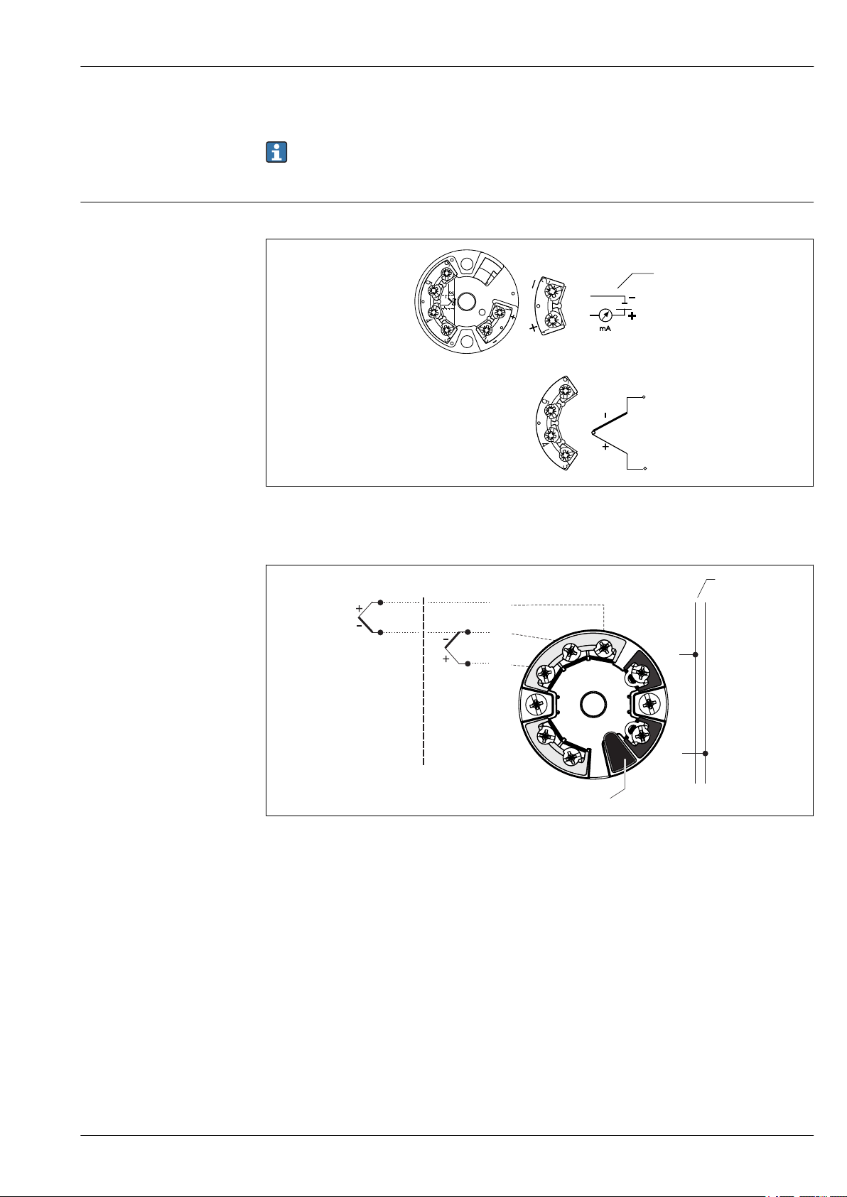
Wiring diagrams
Wiring diagrams for TC and RTD connection
A0033074
2 Wiring diagram of the single sensor input head transmitters (TMT18x)
1 Power supply head transmitter and analog output 4 to 20 mA, or bus connection
Endress+Hauser 7
A0033075
3 Wiring diagram of the dual sensor input head transmitters (TMT8x)
1 Sensor input 1
2 Sensor input 2
3 Bus connection and supply voltage
4 Display connection
Page 8
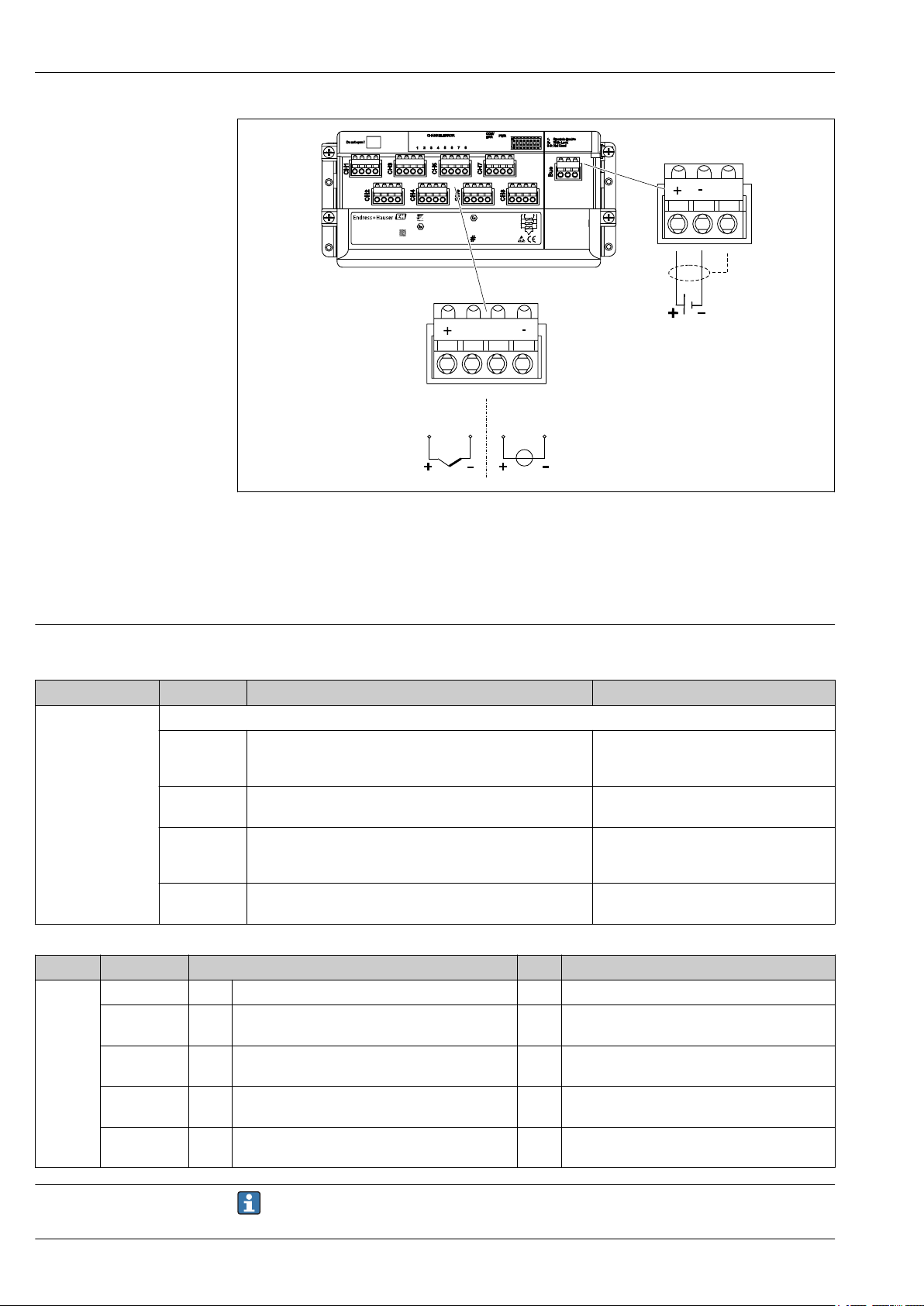
1
CHANNEL ERROR
COM/
ERR
1:
2:
3-8: Not Used
Write Lock
Simulate Enable
PWR
2
3
5
6
7
8
4
Do not open !
CH1
TC
mV
CH1...CH8
H
H
H
S
L
L
L
FOUNDATION
Fieldbus
TM
0032
0123456789101
1019876543210
TMT125-XXXXXXXX
Ser.No.:
TAG No.:
Order Code:
TMT125
PTB 05ATEX xxxxX
II 3G EEx nAII T4
II 3G EEx nLIIC T4
II (3)G [EEx nL] IICT4
PTB 05ATEX xxxx
II2 (1G/D)G EEx ia IICT4
II(1) GD [EEx ia ] IIC
-40°C<Ta < 70°C
FISCO according to IECTS 60079-27
DEVICE ID 452B4810CD-...
Avoid electrostatic charge!
inst. per XA056R/09/a3/XX.XX
-
LH
+
#
4 Wiring diagram of multi-channel transmitter
iTHERM MultiSens Slim TMS21
A0033071
Performance characteristics
Accuracy
Standard Type Standard tolerance Special tolerance (on request)
ASTM E230/ MC.
96.1
Standard Type Standard tolerance Special tolerance (on request)
IEC60584 Class Deviation Class Deviation
K (NiCr-Ni) 2 ±2.5 °C (±4.5 °F) (–40 to 333 °C (–40 to 631.4 °F)
J (Fe-CuNi) 2 ±2.5 °C (±4.5 °F) (–40 to 333 °C (–40 to 631.4 °F)
N (NiCrSINiSi)
E (NiCr-CuNi) 2 ±2.5 °C (±4.5 °F) (–40 to 333 °C (–40 to 631.4 °F)
Deviation, the larger respective value applies
K (NiCr-Ni) ±2.2 K (±3.96 °F) or ±0.02 · |t| (–200 to 0 °C (–328 to 32 °F)
J (Fe-CuNi) ±2.2 K (±3.96 °F) or ±0.0075 · |t| (0 to 760 °C (32 to 1 400 °F) ±1.1 K (±1.98 °F) or ±0.004 · |t|
N (NiCrSINiSi)
E (NiCr-CuNi) ±1.7 K (±3.06 °F) or ±0.01 · |t| (–200 to 0 °C (–328 to 32 °F)
Permissible deviation limits of thermoelectric voltages from standard characteristic for
thermocouples as per IEC 60584 and ASTM E230/ANSI MC96.1:
±1.1 K (±1.98 °F) or ±0.004 · |t|
±2.2 K (±3.96 °F) or ±0.0075 · |t|
(0 to 1 260 °C (32 to 2 300 °F)
±2.2 K (±3.96 °F) or ±0.02 · |t| (–200 to 0 °C (–328 to 32 °F)
±2.2 K (±3.96 °F) or ±0.0075 · |t|
(0 to 1 260 °C (32 to 2 300 °F)
±1.7 K (±3.06 °F) or ±0.005 · |t| (0 to 870 °C (32 to 1 598 °F)
±0.0075 · |t| (333 to 1 200 °C (631.4 to 2 192 °F)
±0.0075 · |t| (333 to 750 °C (631.4 to 1 382 °F)
2 ±2.5 °C (±4.5 °F) (–40 to 333 °C (–40 to 631.4 °F)
±0.0075 · |t| (333 to 1 200 °C (631.4 to 2 192 °F)
±0.0075 · |t| (333 to 900 °C (631.4 to 1 652 °F)
1 ±1.5 °C (±2.7 °F) (–40 to 375 °C (–40 to 707 °F))
1 ±1.5 °C (±2.7 °F) (–40 to 375 °C (–40 to 707 °F))
1 ±1.5 °C (±2.7 °F) (–40 to 375 °C (–40 to 707 °F))
1 ±1.5 °C (±2.7 °F) (–40 to 375 °C (–40 to 707 °F))
(0 to 1 260 °C (32 to 2 300 °F)
(0 to 760 °C (32 to 1 400 °F)
±1.1 K (±1.98 °F) or ±0.004 · |t|
(0 to 1 260 °C (32 to 2 300 °F)
±1 K (±1.8 °F) or ±0.004 · |t|
(0 to 870 °C (32 to 1 598 °F)
±0.004 · |t| (375 to 1 000 °C (707 to 1 832 °F)
±0.004 · |t| (375 to 750 °C (707 to 1 382 °F)
±0.004 · |t| (375 to 1 000 °C (707 to 1 832 °F)
±0.004 · |t| (375 to 800 °C (707 to 1 472 °F)
Response time
8 Endress+Hauser
Response time for the sensor assembly without transmitter.
Page 9

iTHERM MultiSens Slim TMS21
Tmax depending on thermocouple types [°C]
Diameter N K J E
1,5 920 920 440 510
1 700 700 260 300
0,5 700 700 260 300
Thermocouple (TC)
Test architecture
Multimeter Keithley 2000
Fluid bath for response time tests
Test description
Tests in water at 0.4 m/s (1.3 ft/s), according to IEC 60751 and ASTM E644; 10 K temperature step
change.
At the beginning the thermometer to be tested is stabilized in its raised position, outside the fluid at
ambient temperature, then it is immersed rapidly in the fluid bath. The measurement of the output
values of the thermometer is started at latest at instant the thermometer enters the bath, and the
recording is continued until the thermometer has reached the fluid temperature.
Additional tests (on request)
Calibration
Tested thermowell diameter and length Average response time at a temperature of 177 °C
6 mm (0.24 in), 4 520 mm (177.95 in) t
50
t
63
t
90
3 s
4.1 s
9 s
• Functional test measurement at a fixed temperature over the entire thermowell: the multipoint
product under test is simultaneously checked by comparing its individual sensors with a reference
multipoint device having an already known behavior and accuracy. This test has not to be seen as a
calibration test.
• Thermal excitation: this test allows the evaluation of the response time of each measuring point
when a local thermal excitation is applied. Additionally it shows the effects of the local excitation
on the closest points due to the thermal equalization effect of the thermowell sheath.
Calibration is a service that can be performed in house, either on single sensors before assembling or
on the complete device before dispatching.
Calibration involves comparing the measured values of the sensing elements of the multipoint
inserts (DUT device under test) with those of a more precise calibration standard using a defined and
reproducible measurement method. The aim is to determine the deviation of the DUT measured
values from the true value of the measured variable.
Two different methods are used for the inserts:
• Calibration at fixed-point temperatures, e.g. at the freezing point of water at 0 °C (32 °F).
• Calibration compared against a precise reference thermometer.
Evaluation of inserts
If a calibration with an acceptable uncertainty of measurement and transferable measurement
results is not possible, Endress+Hauser offers an insert evaluation measurement service, if
technically feasible.
Installation
Mounting location
Endress+Hauser 9
The installation location must meet the requirements listed in this documentation, such as ambient
temperature, protection classification, climatic class, etc... Care should be taken when checking the
sizes of possible existing support frames or brackets welded on the reactor’s wall (usually not
included in the scope of delivery) or of any other existing frame in the installation area.
Page 10

iTHERM MultiSens Slim TMS21
1
2
Orientation
It is recommended to install the multipoint thermometer in vertical configuration. When vertical
installation is not possible, care has to be taken in order to ensure that the reinforcing sleeve is not
under bending loads due to the any conduit cable tension.
When the flexible configuration is ordered, even not aligned routings are allowed thanks to the
flexible part of the thermowell.
Installation instructions
A0033848
5 Main configuration possibilities
1 Vertical installation with rigid configuration
2 Installation with flexible configuration
The multipoint thermometer is designed to be installed by means of a compression fitting, when
necessary with a flange mounted on a vessel, reactor, tank or similar environment.
The thermometer has been developed to ensure utmost flexibility in terms of possible routing
through any encumbrance and constraint taht can be met in any plant. It guarantees a high sealing
level, noiseless signals, and high mechanical protection of the extension cables.
All parts and components have to be handled with care. During the installation phase, lifting and
introduction of the equipment through the preset nozzle, the following must be avoided:
• Misalignment with the nozzle axis.
• Any load on the welded or threaded parts due to the action of the weight of the device.
• Overtightening of the compression fittings.
• Any tensile and torsional load on the conduit cable.
• Any bending load on the conduit cable.
• Fixing the extension conduit on the plant's infrastructures without allowing axial displacements or
movements.
• Deformation or crushing of the threaded components, bolts, nuts, cable glands and compression
fittings.
10 Endress+Hauser
Page 11

iTHERM MultiSens Slim TMS21
• Bending radius of the flexible part of the thermowell smaller than 20 times the diameter of the
flexible hose.
• Tension loads on the flexible part.
• Friction between the flexible part and the internals of the reactor.
• Fixing the flexible part on the reactor's infrastructures without allowing axial displacements or
movements.
Environment
Ambient temperature range
Storage temperature
Humidity
Configuration without junction box: –50 to +95 °C (–58 to +203 °F)
Configuration with junction box, ordered as accessory:
Junction box Non-hazardous area Hazardous area
Without mounted transmitter –50 to +85 °C (–58 to +185 °F) –50 to +60 °C (–58 to +140 °F)
With mounted head
transmitter
With mounted multi-channel
transmitter
Configuration without junction box: –50 to +95 °C (–58 to +203 °F)
Configuration with junction box, ordered as accessory:
Junction box
With head transmitter –50 to +95 °C (–58 to +203 °F)
With multi-channel transmitter –40 to +80 °C (–40 to +176 °F)
With DIN rail transmitter –40 to +95 °C (–40 to +203 °F)
Condensation according to IEC 60068-2-33:
• Head transmitter: Permitted
• DIN rail transmitter: Not permitted
Maximum relative humidity: 95% according to IEC 60068-2-30
–40 to +85 °C (–40 to +185 °F) Depends on the respective hazardous area
approval. Details see Ex documentation.
–40 to +85 °C (–40 to +185 °F) –40 to +70 °C (–40 to +158 °F)
Degree of protection
Electromagnetic compatibility (EMC)
• Extension conduit: IP68
• Junction box: IP66/67
Depending on the head transmitter used. For detailed information see the related Technical
Information, listed at the end of this document. → 24
Process
The process temperature and process pressure are the minimum input parameters for the selection
of the right product configuration. If special product features are requested, additional data such as
process fluid type, phases, concentration, viscosity, stream and turbulences, corrosion rate have to be
considered as mandatory for the whole product definition.
Process temperature range
Endress+Hauser 11
Up to +500 °C (+932 °F).
Page 12

iTHERM MultiSens Slim TMS21
Process pressure range
0 to 90 bar (0 to 1 305 psi)
Anyhow, the maximum required process pressure has to be combined according to the
maximum allowable process temperature. Process connections like compression fittings and
flanges with their specific ratings, selected according to the plant requirements, define the
maximum process conditions at which the device has to operate.
Endress+Hauser experts can support the customer on any related questions.
Process applications
• Syngas Treatment
• Methanol and Urea production
• Ammonia process
• Ethylene Oxide / Ethylene Glycol production
• Purified Terephthalic Acid (PTA) production
• Polyethylene Terephthalate (PET) production
• Vinyl Chloride Monomer (VCM) production
• Methyl Methacrylat (MMA) production
• Polyurethane (PUR) production
• Tube bundle reactor
• Pilot plants temperature measurement
Higher pressures can be achieved according to the specific process requirements by selecting the
correct flange, compression fittings and materials that are permanently consistent to the process
temperature.
Design, dimensions
Mechanical construction
The overall multipoint assembly is composed of standardized parts with different features allowing a
wide range of product configurations. Different inserts, in terms of TC types, standards, materials,
lengths and thermowells are available. They can be selected based upon specific process conditions,
in order to have the highest application match and the most extended lifetime. Associated extension
cables are provided with high resistance sheath materials and shielded for steady and noiseless
signals signals, protected by a polymeric condiut to withstand different environmental conditions
(salt, sand, humidity, etc.). The transition between the probe and the conduit is obtained by the
usage of a main bushing, containing the electrical junctions between the TC sensors and the
extension cables. It is completely sealed to ensure the declared degree of protection IP68.
It also works as the transition part between the reinforcing sleeve and the conduit cable for signal
communication. The reinforcing sleeve is the dedicated probe’s zone to adjust the immersion length
through sliding compression fittings or flanges. For the flexible configuration the reinforcing sleeve
has integrated the flexible thermowell that allows non-linear routings into the process. If there is a
misalignment between the installation connection and the direction of the measurement given by
the rigid part of the thermowell, the flex configuration is the proper solution.
12 Endress+Hauser
Page 13

iTHERM MultiSens Slim TMS21
B
A C M
LMPn
LMP1
RD
TD
BA
H
FD
RD
M
TD
LMPn
LMP1
Standard design
Flexible design
FL
L
L
FL
A0033087
6 Design of the modular multipoint thermometer. All dimensions in mm (in)
A Conduit cable length
B Main bushing length (for configuration with max. 39 points = 220 mm (8,66 in), for configuration with more
than 39 points = 240 mm (9,45 in))
C Reinforcing sleeve length
FD Flexible part diameter
FL Flying leads length
H Flexible part length
L
Immersion length of sensing elements
MPx
L Device length
M Thermowell length
RD Reinforcement diameter
TD Thermowell diameter
Conduit cable length A and flying leads length FL in mm (in)
A: Maximum 5 000 mm (197 in), minimum 1 000 mm (39.4 in)
FL: Maximum 500 mm (19.7 in)
Specifically customized lengths are provided.
Reinforcing sleeve length C in mm (in)
180 (7.1)
Specifically customized lengths are available on request.
Immersion lengths MPx of sensing elements:
Max. 13 m (512 in)
Specifically customized lengths are available on request.
Flexible hose length H:
Max. 4 000 mm (157 in)
Specifically customized lengths are available on request.
Compression fitting pressure rating at ambient temperature
NPT/ISO Size Bar psi
1/4" 550 8000
1/2" 530 7700
3/4" 500 7300
1" 370 5300
Endress+Hauser 13
Page 14

iTHERM MultiSens Slim TMS21
Thermowell diameter
Different insert types are available. For any different requirement that is not described here,
please contact the Endress+Hauser sales department.
Diameter in mm (in) Sheath material TC type Standard Hot junction type for TC
• 3.2 mm (0.13 in)
• 6 mm (0.24 in)
• 6.35 mm (0.25 in)
• 8 mm (0.31 in)
• 9.5 mm (0.37 in)
Rigid Main bushing 316 + 316L
Reinforced sleeve + thermowell 316 + 316L, 347/321,
Flex Main bushing 316 + 316L
Reinforced sleeve 316 + 316L / 347 / 321,
Thermowell 316 + 316L, 347/321,
Flexible part Inconel600 / 347 (specification on request)
316, 316L
Inconel600
316Ti
321
347
1x type K
1x type J
2x type K
2x type J
Inconel600/316Ti
Inconel600 / 316Ti
Inconel600/316Ti
321 / 316 + 316L (standard)
IEC 60584
ASTM E230
Grounded
Ungrounded
Weight
Materials of insert sheath, thermowell, main bushing and all wetted parts
For increased reliability, Endress+Hauser can offer double hot junction sensors for a sensor
backup function, either by mean of double thermocouples or by coupling two independent
sensors (having the same length). Improved monitoring can be achieved in combination with
double channel transmitters TMT8x.
Maximum number of inserts for every combination of thermowell and insert diameter
Thermowell OD in mm (in)
3.2 (0.13) 6 (0.24) 6.35 (0.25) 8 (0.31) 9.5 (0.37)
Insert diameter in mm (in) 0.5 (0.02) 8 28 22 46
0.8 (0.03) 3 15 12 24 30
1 (0.04) 2 10 8 18 22
1.5 (0.06) 1 6 4 8 12
1) for this configuration the main bushing have to be specially engineered
1)
59
1)
The weight can vary depending on the configuration: extension and thermowell length, type and
dimensions of process connection as well as the number of inserts.
The temperatures for continuous operation specified in the following table are only intended as
reference values for use of the various materials in air and without any significant compressive load.
14 Endress+Hauser
Page 15

iTHERM MultiSens Slim TMS21
The maximum operation temperatures are reduced considerably in some cases where abnormal
conditions such as high mechanical load occur or in aggressive media.
Material
name
AISI
316/1.4401
AISI 316L/
1.4404
1.4435
Alloy600/
2.4816
AISI
304/1.4301
AISI 304L/
1.4307
AISI 316Ti/
1.4571
Short form Recommended
max.
temperature for
continuous use
in air
X5CrNiMo 17-12-2 650 °C (1 202 °F) • Austenitic, stainless steel
X2CrNiMo17-12-2
X2CrNiMo18-14-3
NiCr15Fe 1 100 °C
X5CrNi18-10 850 °C (1 562 °F) • Austenitic, stainless steel
X2CrNi18-9 850 °C (1 562 °F) • Good welding properties
X6CrNiMoTi17-12-2 700 °C (1 292 °F) • Addition of titanium means increased resistance
650 °C (1 202 °F) • Austenitic, stainless steel
(2 012 °F)
Properties
• High corrosion resistance in general
• Particularly high corrosion resistance in chlorinebased and acidic, non-oxidizing atmospheres
through the addition of molybdenum (e.g.
phosphoric and sulfuric acids, acetic and tartaric
acids with a low concentration)
• High corrosion resistance in general
• Particularly high corrosion resistance in chlorinebased and acidic, non-oxidizing atmospheres
through the addition of molybdenum (e.g.
phosphoric and sulfuric acids, acetic and tartaric
acids with a low concentration)
• Increased resistance to intergranular corrosion
and pitting
• Compared to 1.4404, 1.4435 has even higher
corrosion resistance and a lower delta ferrite
content
• A nickel/chromium alloy with very good
resistance to aggressive, oxidizing and reducing
atmospheres, even at high temperatures
• Resistance to corrosion caused by chlorine gases
and chlorinated media as well as many oxidizing
mineral and organic acids, sea water etc.
• Corrosion from ultrapure water
• Not to be used in sulfur-containing atmospheres
• Well usable in water and lowly pollute waste
water
• Only at relatively low temperatures resistant to
organic acids, saline solutions, sulphates,
alkaline solutions, etc.
• Impervious to intergranular corrosion
• High ductility, excellent drawing, forming, and
spinning properties
to intergranular corrosion even after welding
• Broad range of uses in the chemical,
petrochemical and oil industries as well as in coal
chemistry
• Can only be polished to a limited extent, titanium
streaks can form
Endress+Hauser 15
Page 16

iTHERM MultiSens Slim TMS21
Material
name
AISI
321/1.4541
AISI
347/1.4550
Process connection Flanges
Examples of most common flanges according to the following standards: ASME, EN
Standard
ASME ½", 1”, 1½”, 2”, 3”, 4” 150#, 300# AISI 316, 316L, 316Ti, 321, 347
EN DN15, DN25, DN32, DN40, DN50 PN10,PN16, PN40
Short form Recommended
max.
temperature for
continuous use
in air
X6CrNiTi18-10 815 °C (1 499 °F) • Austenitic stainless steel
X6CrNiNb10-10 800 °C (1 472 °F) • Austenitic stainless steel
1)
Size Rating Material
Properties
• High resistance to intergranular corrosion even
after welding
• Good welding characteristics, suitable to all
standard welding methods
• It is used in many sectors of the chemical
industry, petrochemical, and pressurized vessels
• Good resistance to a wide variety of
environments in the chemical, textile, oilrefining, dairy and food industries
• Added niobium makes this steel impervious to
intergranular corrosion
• Good weldability
• Main applications are furnace fire walls, pressure
vessels, welded structures, turbine blades
2)
1) Other flange standards are available on request. Please refer to our technicians for support.
2) Plated flanges with special alloys (i.e. Alloy 600) are available
Compression fittings
The compression fittings are used directly as the process connection or welded or threaded into the
flange to ensure proper process tightness and performances. Dimensions are coherent with the
reinforcing sleeve dimensions.
Operability
For details of operability, see the Technical Information of the Endress+Hauser temperature
transmitters or the manuals of the related operating software. → 24
16 Endress+Hauser
Page 17

iTHERM MultiSens Slim TMS21
Certificates and approvals
CE Mark
Hazardous area approvals
Certification HART
Certification FOUNDATION Fieldbus
Certification PROFIBUS® PA
The complete assembly is provided with individual components CE marked, to ensure safe use in
hazardous areas and pressurized environments.
The Ex approval applies to individual components like junction box, cable glands, terminals. For
further details on the available Ex versions (ATEX, UL, FM, CSA, IEC-EX, NEPSI, EAC-EX), please
contact your nearest Endress+Hauser sales organization. All relevant data for hazardous areas can
be found in separate Ex documentation.
ATEX Ex ia inserts are available only for diameters ≥ 1.5 mm (0.6 in). For further details contact an
Endress+Hauser technician.
The HART® temperature transmitter is registered by the FieldComm Group. The device meets the
requirements of the HART® Communication Protocol Specifications.
The FOUNDATION Fieldbus™ temperature transmitter has successfully passed all test procedures
and is certified and registered by the Fieldbus Foundation. The device thus meets all the
requirements of the following specification:
• Certified according to FOUNDATION Fieldbus™ specification
• FOUNDATION Fieldbus™ H1
• Interoperability Test Kit (ITK), up to date revision status (device certification no. available on
request): the device can also be operated with certified devices of other manufacturers
• Physical layer conformance test of the FOUNDATION Fieldbus™
The PROFIBUS® PA temperature transmitter is certified and registered by the PNO (PROFIBUS®
Nutzerorganisation e. V.), PROFIBUS user organization. The device meets all the requirements of the
following specifications:
• Certified according to FOUNDATION Fieldbus™ specification
• Certified in accordance with PROFIBUS® PA Profile (the up to date profile version is available on
request)
• The device can also be operated with certified devices of other manufacturers (interoperability)
Other standards and guidelines
Material certification
Test report and calibration
Final assembly functional test, temperature profile test report
Final inspection report
• EN 60079: ATEX certification for hazardous areas
• IEC 60529: Degree of protection of housing (IP code)
• IEC 60584 and ASTM E230/ANSI MC96.1: Thermocouples
The material certificate 3.1 (according to EN 10204) can be requested separately. The certificate
includes a declaration related to the materials used to produce the thermometer. It guarantees the
traceability of the materials through the identification number of the multipoint thermometer.
The "Factory calibration" is carried out according to an internal procedure in a laboratory of Endress
+Hauser accredited by the European Accreditation Organization (EA) to ISO/IEC 17025. A
calibration which is performed according to EA guidelines (SIT/Accredia) or (DKD/DAkkS) may be
requested separately. The calibration is performed on the inserts of the multipoint.
Measurement test performed with a given thermal gradient distributed over the entire thermowell
length: this test allows to validate the positioning of each measuring point, its location and the
relative correct wiring in case of a Junction box.
It consists of a series of tests carried on the thermowell in order to ensure that the assembly has all
the required characteristics according to the customer order and the product functionality. It
comprises:
• Visual and dimensions test
• Dye penetrant test on weldings and on tip thermowell closure
• Helium leakage test (when foreseen)
• Material Certificate according to EN10204 3.1
Endress+Hauser 17
Page 18

iTHERM MultiSens Slim TMS21
Additional tests
• Visual and dimension test for all components (Insert, protecting sheath, conduit, adapters)
• Insulation resistance (TC insert) acc. to IEC 1515
• Continuity, polarity (0°C Test) and type (TC insert) acc. to IEC 584.
• Wiring check in combination with the junction box (when foreseen)
18 Endress+Hauser
Page 19

iTHERM MultiSens Slim TMS21
Ordering information
For an overview of the scope of delivery see the configuration table below.
Detailed ordering information is available from your Endress+Hauser Sales Center:
www.addresses.endress.com
Process connection type: Compression fitting
Material 316L, 316H
Others on request
Thread 1", ¾", ½", ¼"
Others on request
Process connection type: Flange
Standard • ANSI
• DIN
• Others on request
Material 316+316L, 316Ti, 304+304L, 321, 347
Others on request
Face • RF
• RTJ
• Others on request
Size • ½", 1", 1½", 2", 3", 4"
• DN15, DN25, DN40, DN50, DN80, DN100
• Others on request
________
________
________
________
________
________
________
________
________
________
Insert and thermowell design
Type TC: K, J, N, E ________
Design • Single
• Duplex
Execution • Grounded
• Ungrounded
Standard/Class • IEC/Class 1 for TC
• ASTM/Class special for TC
• IEC/Class 2 for TC
• ASTM/Class standard for TC
Thermowell material 316, 316L, Alloy600, 321, 347, 316Ti
Others on request
Thermowell diameter TD in
mm (in)
Thermowell design • Rigid
Flexible conduit cable design
Diameter/material/adapter • DN 29/polyamide/M32
• 3.2 mm (0.13 in)
• 6 mm (0.24 in)
• 6.35 mm (0.25 in)
• 8 mm (0.31 in)
• 9.5 mm (0.37 in)
• Flexible
• DN 36/polyamide/M40
• DN 48/polyamide/M50
1)
________
________
1) Different configuration on request
Endress+Hauser 19
Page 20

Measurement point distribution
Positioning • Equally spaced
• Customized
Number 2 to 59
1)
1) Different numbers/configurations are available on request
iTHERM MultiSens Slim TMS21
________
Insertion length TAG (description) (L
MP
MP
MP
MP
MP
MP
MP
1
2
3
4
5
6
1)
x
_________________________________________ __________
_________________________________________ __________
_________________________________________ __________
_________________________________________ __________
_________________________________________ __________
_________________________________________ __________
_________________________________________ __________
1) Different number/configuration on request
Maximum number of inserts for every combination of thermowell and insert diameter
Thermowell OD in mm (in)
3.2 (0.13) 6 (0.24) 6.35 (0.25) 8 (0.31) 9.5 (0.37)
Insert diameter in mm (in) 0.5 (0.02) 8 28 22 46
0.8 (0.03) 3 15 12 24 30
1 (0.04) 2 10 8 18 22
1.5 (0.06) 1 6 4 8 12
1) for this configuration the main bushing have to be specially engineered
1)
) in mm (in)
MPx
59
1)
20 Endress+Hauser
Page 21

iTHERM MultiSens Slim TMS21
A
B
C
Accessories
Various accessories, which can be ordered with the device or subsequently from Endress+Hauser, are
available for the device. Detailed information on the order code in question is available from your
local Endress+Hauser sales center.
Device-specific accessories
Accessories Description
Junction box The junction box is suited for chemical agents
environments. Sea water corrosion resistance and
extreme temperature variation stability is guaranteed.
Ex-e, Ex-i terminals can be generally installed.
Transmitter Head transmitters
• PC programmable head transmitter
• With HART®-, PROFIBUS® PA or FOUNDATION
FieldbusTM communication protocol
8-channel DIN rail transmitter with FOUNDATION
FieldbusTM communication protocol
Pads, clips, spacers • Pads and clips: in order to fix the multipoint
thermometer along its immersion length.
• Spacer: Used in presence of an existing thermowell in
order to guarantee the centering.
Specific extension for on-board junction box When the junction box cannot be remotely installed, it
has to be configured on-board at the multipoint
thermometer. Therefore, a specific extension design has
to be provided. This design is available on request only
for flanged process connection.
A0030866
7 Junction box as accessory for remote installation
Possible junction box dimensions (A x B x C) in mm (in):
A B C
Stainless Steel Min. 170 (6.7) 170 (6.7) 130 (5.1)
Max. 500 (19.7) 500 (19.7) 240 (9.5)
Aluminium Min. 100 (3.9) 150 (5.9) 80 (3.2)
Max. 330 (13) 500 (19.7) 180 (7.1)
Endress+Hauser 21
Page 22

iTHERM MultiSens Slim TMS21
Maximal possible number
Junction box size N° of TMT8x/18x N° of TMT125 N° of terminal blocks
150x150x100 2 0 12
200x200x160 4 0 20
280x280x160 6 1 60
270x350x130 12 2 90
350x350x160 12 2 135
380x380x160 20 2 159
350x500x160 28 4 225
500x500x160 42 6 360
1) Thermal dissipation ans so maximum number of transmitters has to be checked according to maximum
ambient temperature.
Type of specification Junction box Cable glands
Material AISI 316 / aluminum NiCr Plated brass
Ingress protection (IP) IP66/67 IP66
Ambient temperature range –50 to +60 °C
Approvals IEC-EX, ATEX, UL, FM, CSA,
Marking II 2 GD Ex e IIC Gb
Cover Hinged -
Maximum sealing diameter - 6 to 12 mm (0.24 to 0.47 in)
1)
of head transmitters/terminal blocks:
AISI 316 / 316L
–52 to +110 °C (–61.1 to +140 °F)
(–58 to +140 °F)
NEPSI, EAC-EX approval for
use in hazardous area
approval
Ex ia Ga IIC T
Ex tb IIIC
UL913
FM3610
CSA C22.2 No. 157 Class 1,
Division 1, Groups B, C, D
T6/T5/T4
Communication-specific accessories
Configuration kit TXU10 Configuration kit for PC-programmable transmitter with setup software and
interface cable for PC with USB port
Order code: TXU10-xx
Commubox FXA195
HART
Commubox FXA291 Connects Endress+Hauser field devices with a CDI interface (= Endress+Hauser
HART Loop Converter
HMX50
For intrinsically safe HART communication with FieldCare via the USB interface.
For details, see "Technical Information" TI00404F
Common Data Interface) and the USB port of a computer or laptop.
For details, see "Technical Information" TI00405C
Is used to evaluate and convert dynamic HART process variables to analog current
signals or limit values.
For details, see "Technical Information" TI00429F and Operating Instructions
BA00371F
22 Endress+Hauser
Page 23

iTHERM MultiSens Slim TMS21
Service-specific accessories
Wireless HART adapter
SWA70
Fieldgate FXA320 Gateway for the remote monitoring of connected 4-20 mA measuring devices via a
Fieldgate FXA520 Gateway for the remote diagnostics and remote configuration of connected HART
Field Xpert SFX100 Compact, flexible and robust industry handheld terminal for remote configuration
Accessories Description
Applicator Software for selecting and sizing Endress+Hauser measuring devices:
Is used for the wireless connection of field devices.
The WirelessHART adapter can be easily integrated into field devices and existing
infrastructures, offers data protection and transmission safety and can be operated
in parallel with other wireless networks with minimum cabling complexity.
For details, see Operating Instructions BA061S
Web browser.
For details, see "Technical Information" TI00025S and Operating Instructions
BA00053S
measuring devices via a Web browser.
For details, see "Technical Information" TI00025S and Operating Instructions
BA00051S
and for obtaining measured values via the HART current output (4-20 mA).
For details, see Operating Instructions BA00060S
• Calculation of all the necessary data for identifying the optimum measuring
device: e.g. pressure loss, accuracy or process connections.
• Graphic illustration of the calculation results
Administration, documentation and access to all project-related data and
parameters over the entire life cycle of a project.
Applicator is available:
• Via the Internet: https://wapps.endress.com/applicator
• On CD-ROM for local PC installation.
W@M Life cycle management for your plant
W@M supports you with a wide range of software applications over the entire
process: from planning and procurement, to the installation, commissioning and
operation of the measuring devices. All the relevant device information, such as
the device status, spare parts and device-specific documentation, is available for
every device over the entire life cycle.
The application already contains the data of your Endress+Hauser device. Endress
+Hauser also takes care of maintaining and updating the data records.
W@M is available:
• Via the Internet: www.endress.com/lifecyclemanagement
• On CD-ROM for local PC installation.
FieldCare FDT-based plant asset management tool from Endress+Hauser.
It can configure all smart field units in your system and helps you manage them. By
using the status information, it is also a simple but effective way of checking their
status and condition.
For details, see Operating Instructions BA00027S and BA00059S
Endress+Hauser 23
Page 24

iTHERM MultiSens Slim TMS21
Documentation
• Operating manuals iTEMP temperature transmitters:
– TMT181, PC programmable, single-channel, RTD, TC, Ω, mV (KA141R/09/a3)
– HART® TMT182, single-channel, RTD, TC, Ω, mV (KA142R/09/c4)
– HART® TMT82, two-channel, RTD, TC, Ω, mV (BA01028T/09/en)
– PROFIBUS® PA TMT84, two-channel, RTD, TC, Ω, mV (BA00257R/09/en)
– FOUNDATION FieldbusTM TMT85, two-channel, RTD, TC, Ω, mV (BA00251R/09/en)
– FOUNDATION FieldbusTM TMT125, 8 channel, RTD, TC, Ω, mV (BA00240R/09/en)
• Technical Information of inserts:
Thermocouple insert Omnigrad T TSC310 (TI00255t/09/en)
• Technical Information application example:
– RN221N active barrier, for supplying loop-powered 2-wire transmitters (TI073R/09/en)
– HAW562 surge arresters, (TI01012K/09/en)
www.addresses.endress.com
 Loading...