

Page 1
TI01399T/09/EN/02.19
71456860
2019-10-21
Products
Solutions Services
Technical Information
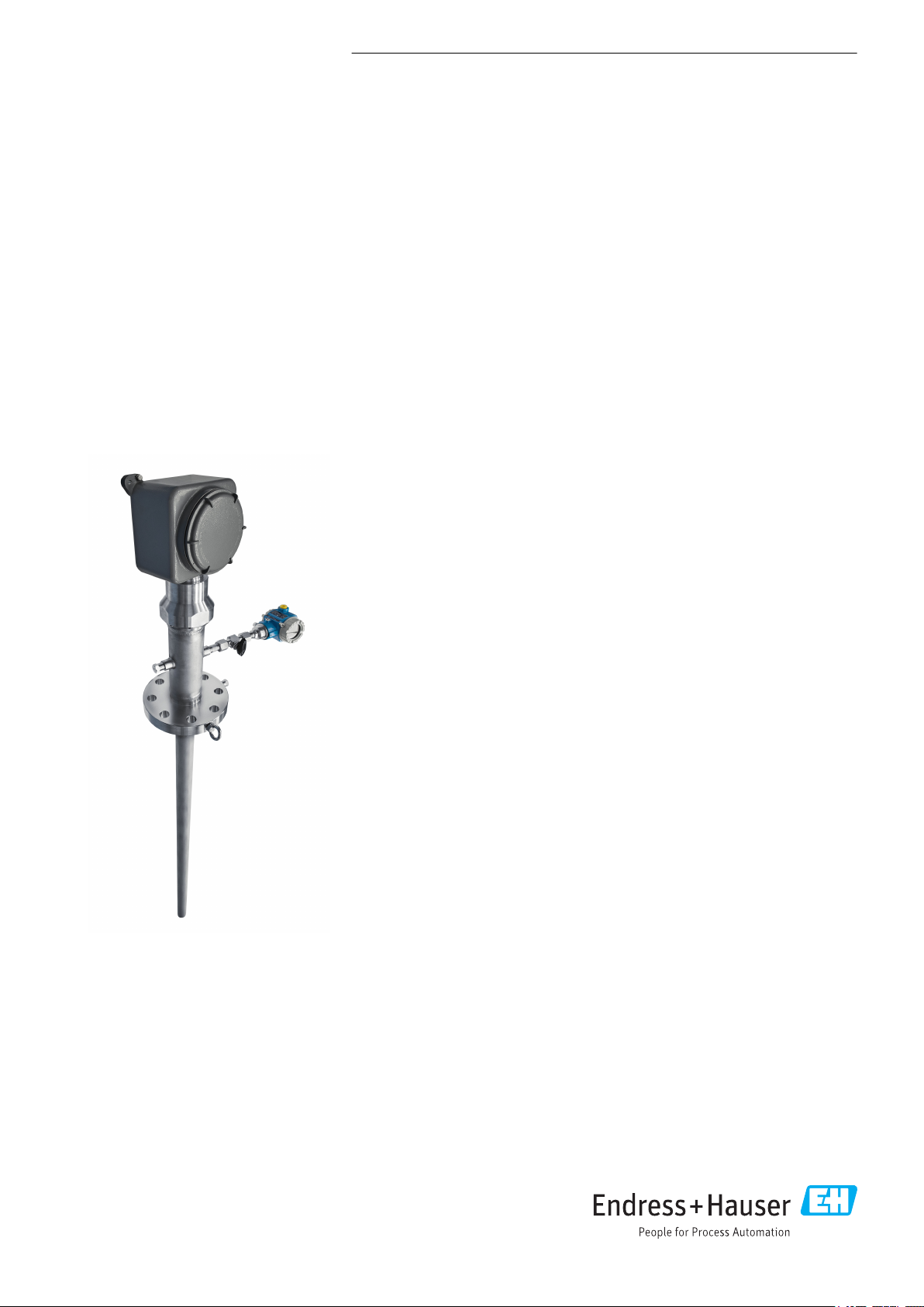
iTHERM TMS12
MultiSens Linear
Modular TC and RTD multipoint with primary
thermowell (with diagnostic chamber)
Application
• Easy-to-use device with modular design, provided of its own primary thermowell
and ready to be installed
• Specifically designed for Oil & Gas and Petrochemical processing industries
• Measuring range:
• Resistance insert (RTD): –200 to 600 °C (–328 to 1 112 °F)
• Thermocouple (TC): –270 to 1 100 °C (–454 to 2 012 °F)
• Static pressure range: Up to 240 bar (3 481 psi). Specific maximum process
pressure achievable depending on process type and temperature
• Degree of protection: IP66/67
Head transmitter
All Endress+Hauser transmitters are available with enhanced accuracy and reliability
compared to directly wired sensors. Easy customizing by choosing one of the
following outputs and communication protocols:
• Analog output 4 to 20 mA
• HART
• PROFIBUS® PA
• FOUNDATION Fieldbus™
Your benefits
• High degree of customization thanks to a modular product design
• Easy integration due to IEC 60584, ASTM E230 and IEC 60751 inserts
• Electrical and Pressure Directive compliance for an easy process integration
• Compliance to different types of protection for use in hazardous locations for a
• Possibility to individually replace inserts, even in operating conditions
• Superior mechanical strength thanks to a primary thermowell for temperature
• Advanced diagnosis to monitor the performances of the complete thermometric
®
wide and easy process integration
sensors protection
device during its operating time and to plan in advanced any maintenance action
Page 2

Table of contents
iTHERM TMS12 MultiSens Linear
Function and system design ................... 3
Measuring principle ............................ 3
Measuring system ............................. 3
Equipment architecture ......................... 4
Input ..................................... 7
Measured variable ............................. 7
Measuring range .............................. 7
Output ................................... 7
Output signal ................................ 7
Family of temperature transmitters ................. 7
Power supply .............................. 8
Wiring diagrams .............................. 8
Performance characteristics ................... 9
Accuracy ................................... 9
Response time .............................. 10
Shock and vibration resistance .................... 10
Calibration ................................. 10
Installation ............................... 11
Mounting location ............................ 11
Orientation ................................ 11
Installation instructions ........................ 11
Other standards and guidelines ................... 25
Material certification .......................... 25
Test report and calibration ...................... 25
Ordering information ....................... 26
Accessories ............................... 29
Device-specific accessories ...................... 29
Communication-specific accessories ................ 30
Service-specific accessories ...................... 30
Documentation ............................ 31
Environment .............................. 13
Ambient temperature range ..................... 13
Storage temperature .......................... 13
Humidity .................................. 13
Climate class ............................... 13
Electromagnetic compatibility (EMC) ............... 13
Process .................................. 13
Process temperature range ...................... 13
Process pressure range ......................... 14
Mechanical construction .................... 14
Design, dimensions ........................... 14
Weight ................................... 20
Materials .................................. 21
Process connection ........................... 22
Compression fittings .......................... 22
Thermal contacts components .................... 23
Operability ............................... 24
Certificates and approvals ................... 25
CE Mark .................................. 25
Hazardous area approvals ....................... 25
PED approval ............................... 25
Certification HART ........................... 25
Certification FOUNDATION Fieldbus ................ 25
Certification PROFIBUS® PA ..................... 25
2 Endress+Hauser
Page 3

iTHERM TMS12 MultiSens Linear
Function and system design
Measuring principle Thermocouples (TC)
Thermocouples are comparatively simple, robust temperature sensors which use the Seebeck effect
for temperature measurement: if two electrical conductors made of different materials are connected
at a point, a weak electrical voltage can be measured between the two open conductor ends if the
conductors are subjected to a thermal gradient. This voltage is called thermoelectric voltage or
electromotive force (emf.). Its magnitude depends on the type of conducting materials and the
temperature difference between the "measuring point" (the junction of the two conductors) and the
"cold junction" (the open conductor ends). Accordingly, thermocouples primarily only measure
differences in temperature. The absolute temperature at the measuring point can be determined
from these if the associated temperature at the cold junction is known or is measured separately and
compensated for. The material combinations and associated thermoelectric voltage/temperature
characteristics of the most common types of thermocouple are standardized in the IEC 60584 and
ASTM E230/ANSI MC96.1 standards.
Resistance thermometer (RTD)
These resistance thermometers use a Pt100 temperature sensor according to IEC 60751. The
temperature sensor is a temperature-sensitive platinum resistor with a resistance of 100 Ω at
0 °C (32 °F) and a temperature coefficient α = 0.003851 °C-1.
There are generally two different kinds of platinum resistance thermometers:
• Wire wound (WW): Here, a double coil of fine, high-purity platinum wire is located in a ceramic
support. This is then sealed top and bottom with a ceramic protective layer. Such resistance
thermometers not only facilitate very reproducible measurements but also offer good long-term
stability of the resistance/temperature characteristic within temperature ranges up to
600 °C (1 112 °F). This type of sensor is relatively large in size and it is comparatively sensitive to
vibrations.
• Thin film platinum resistance thermometers (TF): A very thin, ultrapure platinum layer,
approx. 1 μm thick, is vaporized in a vacuum on a ceramic substrate and then structured
photolithographically. The platinum conductor paths formed in this way create the measuring
resistance. Additional covering and passivation layers are applied and reliably protect the thin
platinum layer from contamination and oxidation, even at high temperatures. The primary
advantages of thin film temperature sensors over wire wound versions are their smaller sizes and
better vibration resistance. A relatively low principle-based deviation of the resistance/
temperature characteristic from the standard characteristic of IEC 60751 can frequently be
observed among TF sensors at high temperatures. As a result, the tight limit values of tolerance
category A as per IEC 60751 can only be observed with TF sensors at temperatures up to approx.
300 °C (572 °F). For this reason, thin-film sensors are generally only used for temperature
measurements in ranges below 400 °C (752 °F).
Measuring system
Endress+Hauser offers a complete portfolio of optimized components for the temperature measuring
point – everything you need for the seamless integration of the measuring point into the overall
facility.
This includes:
• Power supply unit/active barrier
• Configuration units
• Overvoltage protection
For more information, see the brochure 'System Components - Solutions for a Complete
Measuring Point' (FA00016K/09)
Endress+Hauser 3
Page 4
iTHERM TMS12 MultiSens Linear
1 2
3 4
6
HAW56x
1 IN 2
3 OUT 4
HAW56x
3 OUT 4
1 IN 2
HAW56x
3 OUT 4
1 IN 2
HAW56x
3 OUT 4
1 IN 2
5
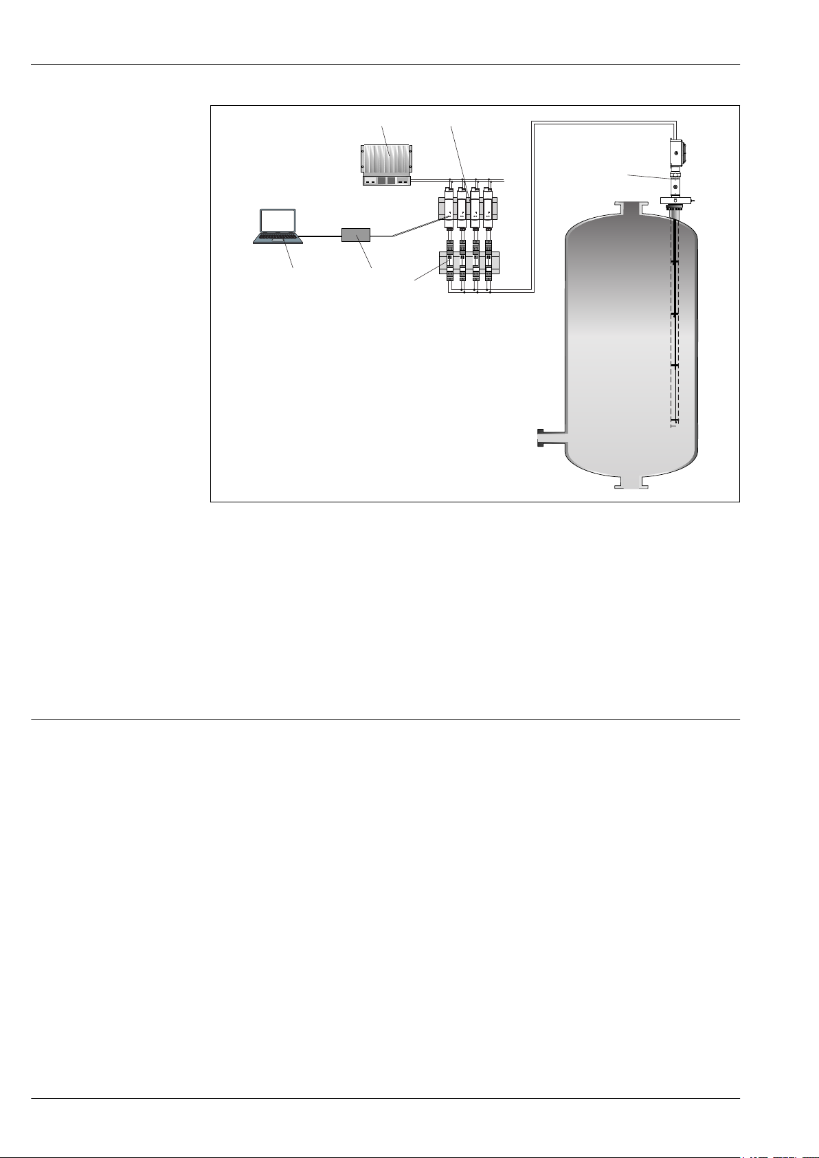
Equipment architecture
A0036464
1 Application example in a reactor.
1 Device configuration with application software FieldCare
2 Commubox
3 PLC
4 Active barrier RN221N (24 VDC, 30 mA) that has a galvanically isolated output for supplying voltage to loop-
powered transmitters. The universal power supply works with an input supply voltage of 20 to 250 V DC/AC;
50/60 Hz, which means that it can be used in all international power grids.
5 Surge arrester modules HAW562 for protection of signal lines and components in hazardous areas, e.g.
4 to 20 mA- , PROFIBUS® PA, FOUNDATION Fieldbus™ signal lines. More information on this can be found
in the Technical Information → 31
6 Mounted multipoint thermometer with its own primary thermowell, optionally with built-in transmitters in
the junction box for 4 to 20 mA-, HART-, PROFIBUS® PA-, FOUNDATION Fieldbus™ communication or
terminal blocks for remote wiring.
The multipoint thermometer belongs to a range of modular product configuration for multipoint
temperature detection with a design where subassemblies and components can be managed
individually for easy maintenance and spare part ordering.
It consists of the following main sub-assemblies:
• Insert: Composed by individual metal sheathed sensing elements (thermocouples or thermosresistance) protected by the primary thermowell welded to the process connection. In addition,
individual guiding tubes or protecting themowells allow inserts replacement during operating
conditions. When applicable, each insert can be handled as an individual spare part and ordered
via specific standard product order codes (e.g. TSC310, TST310) or special codes. For the specific
order code please contact your Endress+Hauser specialist.
• Process Connection: Represented by an ASME or EN flange. It is provided with pressure port and
it might be provided with eyebolts for lifting the device.
• Head: It is composed of a junction box provided with its components such as cable glands, draining
valves, earth screws, terminals, head transmitters, etc.
• Head Support System: It is designed to support the junction box by swivelling joint.
4 Endress+Hauser
Page 5
iTHERM TMS12 MultiSens Linear
1a
2
4
6b
11
7
8
9
3
12
6b
5
1b
2
4
6a
10b
7
10a
9
3
8
11
12
6a
5
• Additional Accessories: They can be ordered for any configuration, and they are recommended in
• Primary Thermowell: It is directly welded to the process connection, designed to guarantee high
• Diagnostic Chamber: This subassembly consists in a closed volume that ensures the continuous
In general, the system measures a linear temperature profile inside the process environment. It is
also possible to obtain a three-dimensional temperature profile by installing more than one
Multisens Linear (either horizontally, vertically or obliquely).
case of replaceable sensors configuration (such as pressure transducers, manifolds, valves and
fitting).
degree of mechanical protection and corrosion resistance.
monitoring of the device conditions during its operating life and safe leakage containment. The
chamber has integrated connections for accessories (such as valves, manifolds). A wide range of
accessories is available to get the highest level of system information (pressure, temperature,
fluids composition and next maintenance step).
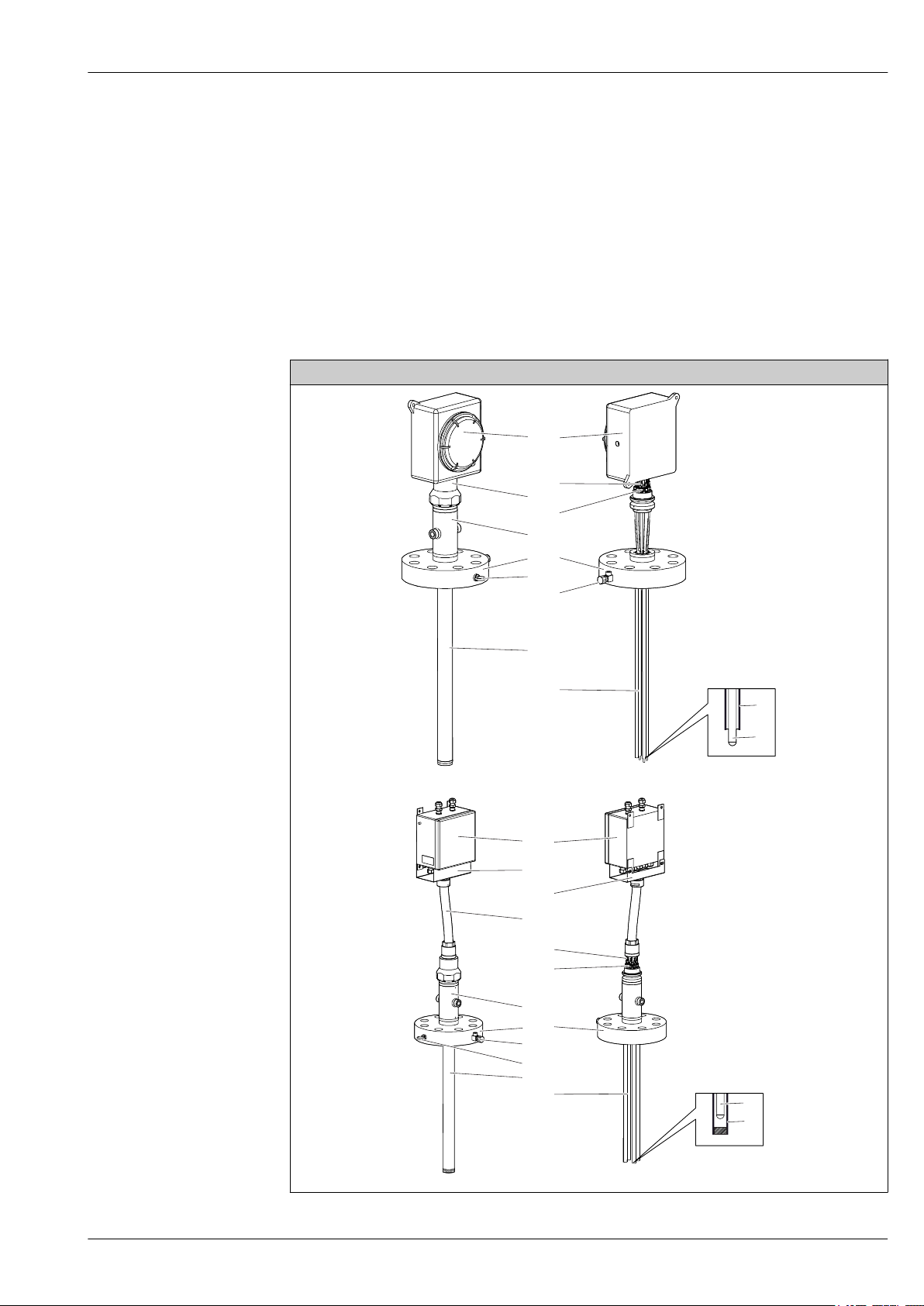
Design
A0036465
A0036466
Endress+Hauser 5
Page 6

iTHERM TMS12 MultiSens Linear
Description, available options and materials
1: Head
1a: Directly mounted
1b: Remote
2: Support System Swivelling support joint for junction box orientation.
3: Primary thermowell The primary thermowell is made by a tube with calculated and
4: Process connection, flanged
according to ASME, or EN standards
5: Insert Mineral insulated grounded and ungrounded thermocouples or RTD
6 Tip design of sensor thermal contacts
6a: for protecting thermowells
6b: for guiding tubes The sensors inside the primary thermowell can be kept in the right
7: Eyebolt Lifting device for easy handling during installation phase.
8: Extension cables Cables for electrical connections between the inserts and junction
9: Pressure port (threaded hole) Auxiliary connections and fittings for pressure detection.
10: Protections
10a: Cable conduit system (in case of
remote head)
10b: Extension cables cover
Hinged or screwed cover junction box for electrical connections. It
includes components such as electrical terminals, transmitters and
cable glandes.
• 316/316L
• Aluminium alloys
• Other materials on request
316/316L
selected thickness according to reference international standards. It is
designed to protect the sensors against harsh process conditions such
as dynamic and static loads and corrosion.
• 316/316L
• 321
• 304/304L
• 310L
Represented by a flange according to international standards, or
engineered to satisfy specific process requirements → 14.
• 316 + 316L
• 304
• 310
• 321
• Other materials on request
(Pt100 wire wound).
For details, refer to the Ordering information table.
The sensors inside the primary thermowell can be kept in the right
measuring location by means of closed-end protecting thermowells
which end with:
• welded thermal block discs to ensure the optimal heat transfer
thorough the primary thermowell wall and the temperature
sensors. Sensors are replaceable.
• individual thermal blocks pressed against the internal wall to
ensure the optimal heat transfer between the primary thermowell
and the replaceable temperature sensor.
• straight tip.
For details, refer to the Ordering information table
measuring location by means of open-end guiding tubes which end
with:
• bimetallic stripes to push the sensor in contact with the internal
wall of the main thermowell and allow faster response time.
Sensors are not replaceable.
• bent tip.
SS 316
box.
• Shielded PVC
• Shielded Hyflon MFA
• Unshielded PVC flying leads
Cable conduit: made by flexible polyamide to connect the top of the
diagnostic chamber and the remote junction box.
Extension cable cover: made by a shaped stainless stell plate fixed to
the junction box frame in order to protect the cable connections.
6 Endress+Hauser
Page 7

iTHERM TMS12 MultiSens Linear
Description, available options and materials
11: Compression fitting High performing fittings for the tightness between the diagnostic
12: Diagnostic chamber
12a: Basic Chamber
12b: Advanced Chamber
Input
chamber-head and the external environment, suitable for a wide
range of process fluids and severe combination between temperature
and pressure.
Diagnostic chamber for leakage detection and safe containment.
System behavior monitoring thanks to a continuous pressure
detection of the contained fluids.
Basic configuration: not replaceable inserts. Extension cables
replaceable in case of accidental damages (through the replacement
of the external insert stump).
Advanced configuration: complete inserts replacement allowed.
Measured variable
Measuring range
Output signal
Temperature (temperature linear transmission behavior)
RTD:
Input Designation Measuring range limits
RTD as per IEC 60751 Pt100 –200 to +600 °C (–328 to +1 112 °F)
Thermocouple:
Input Designation Measuring range limits
Thermocouples (TC) as per IEC
60584, part 1 - using an
Endress+Hauser - iTEMP
temperature head transmitter
Type J (Fe-CuNi)
Type K (NiCr-Ni)
Type N (NiCrSi-NiSi)
Internal cold junction (Pt100)
Cold junction accuracy: ± 1 K
Max. sensor resistance: 10 kΩ
–210 to +720 °C (–346 to +1 328 °F)
–270 to +1 150 °C (–454 to +2 102 °F)
–270 to +1 100 °C (–454 to +2 012 °F)
Output
Generally, the measured value can be transmitted in one of two ways:
• Directly-wired sensors - sensor measured values forwarded without a transmitter.
• Via all common protocols by selecting an appropriate Endress+Hauser iTEMP temperature
transmitter. All the transmitters listed below are mounted directly in the junction box and wired
with the sensory mechanism.
Family of temperature transmitters
Thermometers fitted with iTEMP transmitters are an installation-ready complete solution to
improve temperature measurement by significantly increasing accuracy and reliability, when
compared to direct wired sensors, as well as reducing both wiring and maintenance costs.
PC programmable head transmitters
They offer a high degree of flexibility, thereby supporting universal application with low inventory
storage. The iTEMP transmitters can be configured quickly and easily at a PC. Endress+Hauser offers
free configuration software which can be downloaded from the Endress+Hauser Website. More
information can be found in the Technical Information.
HART® programmable head transmitters
The transmitter is a 2-wire device with one or two measuring inputs and one analog output. The
device not only transfers converted signals from resistance thermometers and thermocouples, it also
transfers resistance and voltage signals using HART® communication. It can be installed as an
intrinsically safe apparatus in Zone 1 hazardous areas and is used for instrumentation in the
terminal head (flat face) as per DIN EN 50446. Swift and easy operation, visualization and
Endress+Hauser 7
Page 8
iTHERM TMS12 MultiSens Linear
3
5
6
RTD
3
4
5
6
RTD
1
2
TC
6
4
3-wire
4-wire
Power supply
head transmitter and
analog output 4 to 20 mA,
or bus connection
(red) (red)
(red) (red)
(white) (white)
(white)
maintenance by PC using operating software, Simatic PDM or AMS. For more information, see the
Technical Information.
PROFIBUS® PA head transmitters
Universally programmable head transmitter with PROFIBUS® PA communication. Conversion of
various input signals into digital output signals. High accuracy over the complete ambient
temperature range. Swift and easy operation, visualization and maintenance using a PC directly from
the control panel, e. g. using operating software, Simatic PDM or AMS. For more information, see
the Technical Information.
FOUNDATION Fieldbus™ head transmitters
Universally programmable head transmitter with FOUNDATION Fieldbus™ communication.
Conversion of various input signals into digital output signals. High accuracy over the complete
ambient temperature range. Swift and easy operation, visualization and maintenance using a PC
directly from the control panel, e.g. using operating software such as ControlCare from Endress
+Hauser or NI Configurator from National Instruments. For more information, see the Technical
Information.
Advantages of the iTEMP transmitters:
• Dual or single sensor input (optionally for certain transmitters)
• Unsurpassed reliability, accuracy and long-term stability in critical processes
• Mathematical functions
• Monitoring of the thermometer drift, sensor backup functionality, sensor diagnostic functions
• Sensor-transmitter matching for dual sensor input transmitter, based on Callendar/Van Dusen
coefficients
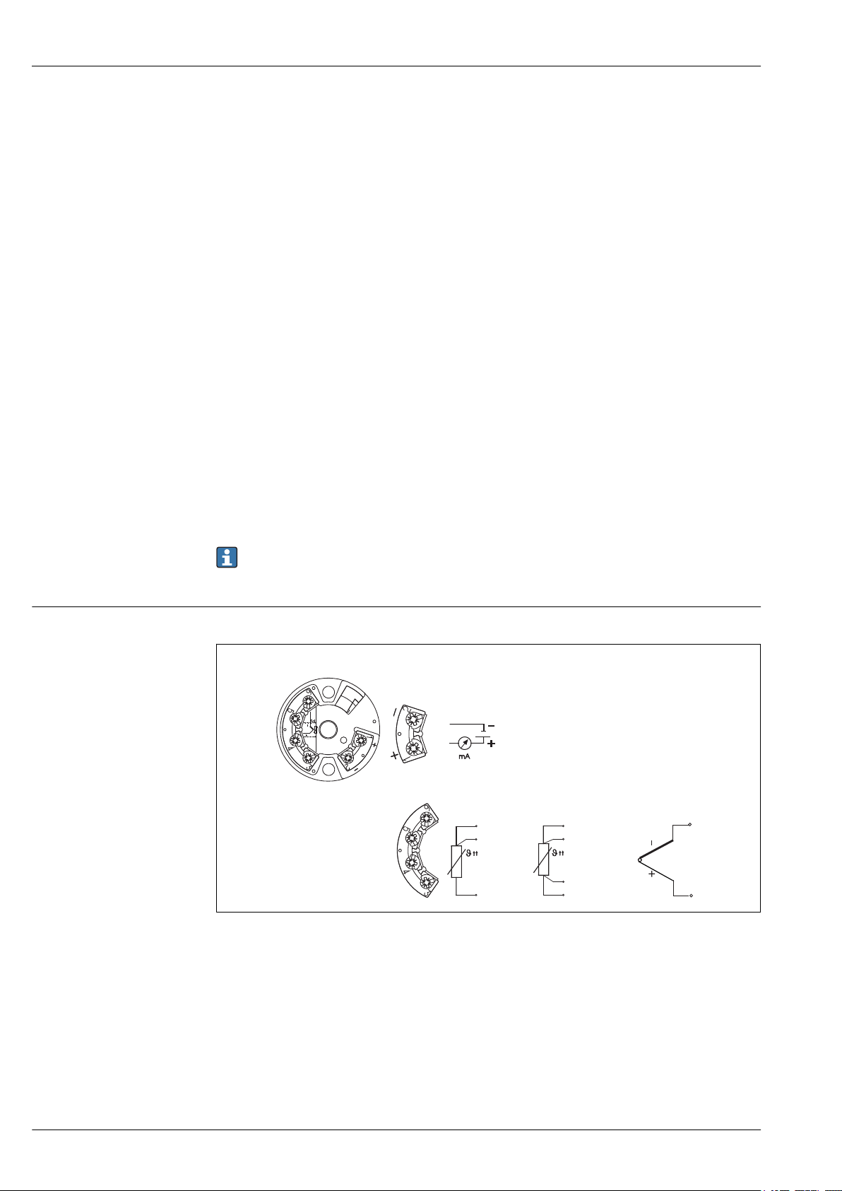
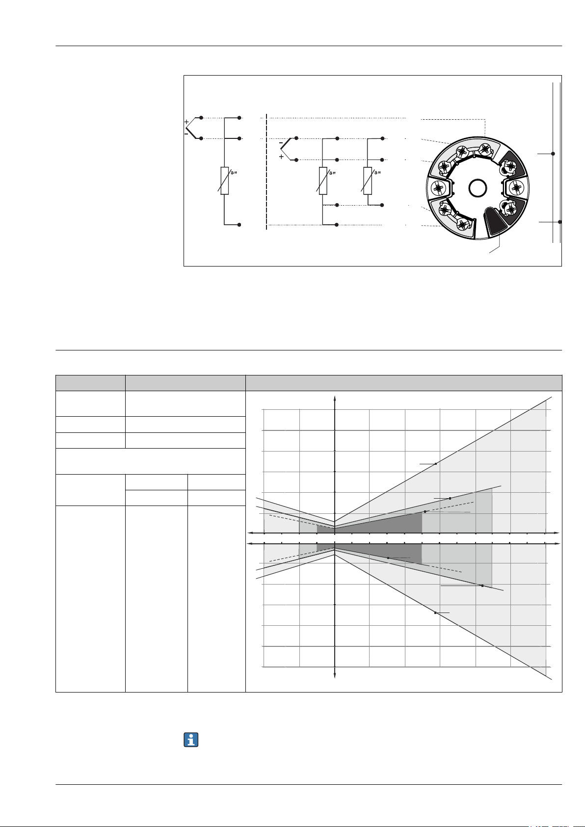
Wiring diagrams
Power supply
• Electrical connecting cables must be smooth, corrosion resistant, easy to be cleaned and
inspected, robust against mechanical stresses, no-humidity sensitivity.
• Grounding or shielding connections are possible via ground terminals on the junction box.
Wiring diagrams for TC and RTD connection
A0016712-EN
2 Wiring diagram of the single sensor input head transmitters (TMT18x)
8 Endress+Hauser
Page 9
iTHERM TMS12 MultiSens Linear
-
+
+
1
-
2
7
6
5
4
3
1
2
7
6
5
4
3
Sensor input 2
Sensor input 1
RTD 4- and 3-wire:
RTD 3-wire:
Bus connection
and supply voltage
Display connection
red
white
red red
red
whitewhite
TC
TC
A
AA
-200 -100 0 100 200 300 400 500 600°C
0.5
1.0
1.5
2.0
B
2.5
3.0
- 0.5
- 1.0
- 1.5
- 2.0
- 2.5
- 3.0
B
A
AA
Max. deviation (°C)
Max. deviation (°C)
3 Wiring diagram of the dual sensor input head transmitters (TMT8x)
A0016711-EN
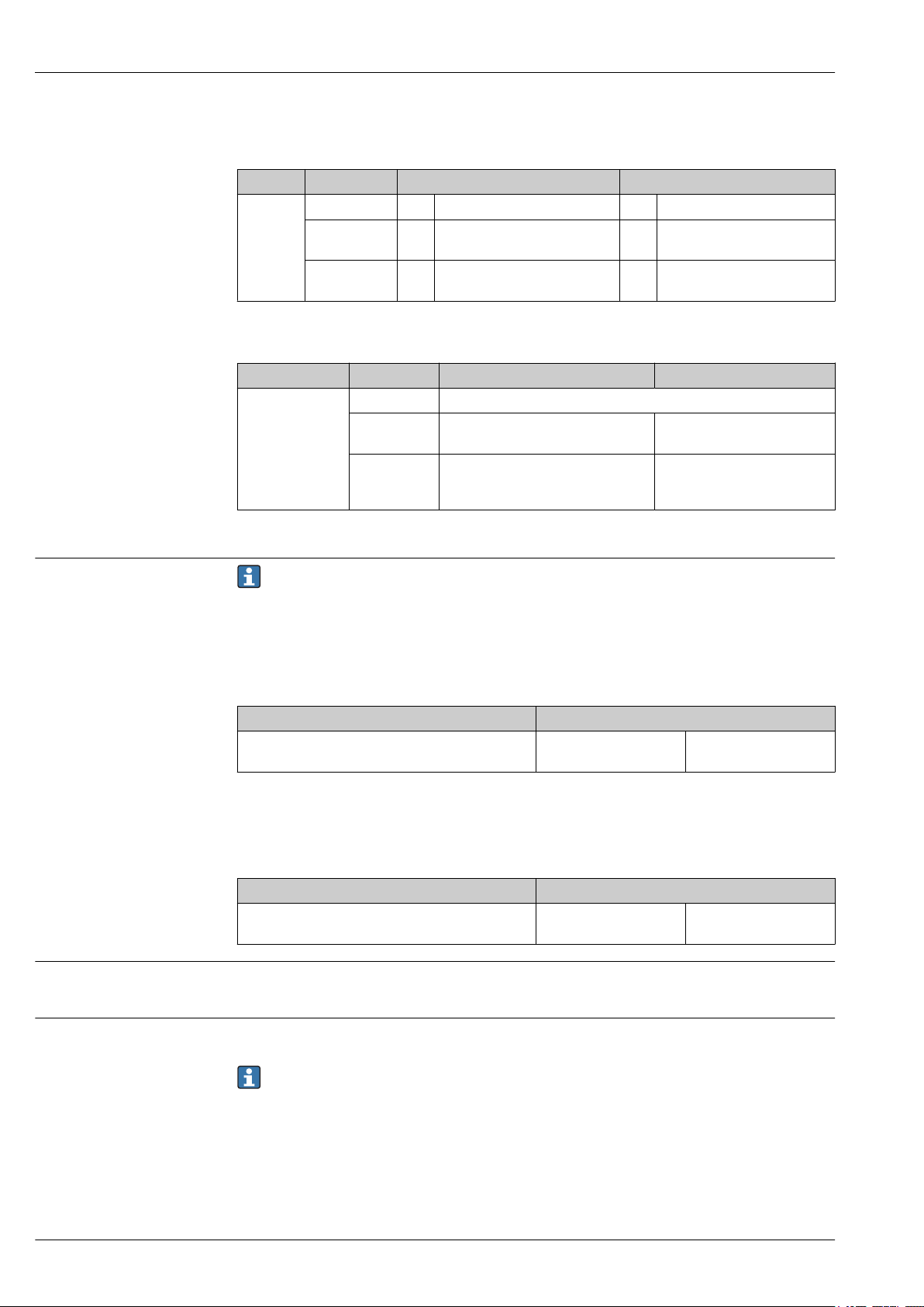
Performance characteristics
Accuracy
Class Max. tolerances (°C) Characteristics
Cl. AA, former 1/3
Cl. B
Cl. A ± (0.15 + 0.002 · |t|
Cl. B ± (0.3 + 0.005 · |t|
Temperature ranges for compliance with the
tolerance classes
Wire wound
sensor (WW):
Thin-film version
(TF):
Standard –30 to +300 °C 0 to +150 °C
± (0.1 + 0.0017 · |t|
Cl. A Cl. AA
–100 to +450 °C –50 to +250 °C
Cl. A Cl. AA
RTD resistance thermometer as per IEC 60751
1)
)
1)
)
1)
)
1) |t| = absolute value °C
Endress+Hauser 9
In order to obtain the maximum tolerances in °F, the results in °C must be multiplied by a factor
of 1.8.
A0008588-EN
Page 10
iTHERM TMS12 MultiSens Linear
Permissible deviation limits of thermoelectric voltages from the standard characteristic for
thermocouples as per IEC 60584 or ASTM E230/ANSI MC96.1:
Standard Type Standard tolerance Special tolerance
IEC 60584 Class Deviation Class Deviation
J (Fe-CuNi) 2 ±2.5 °C (–40 to 333 °C)
±0.0075 |t|
K (NiCr-NiAl)
N (NiCrSi-NiSi)
1) |t| = absolute value °C
Standard Type Standard tolerance Special tolerance
ASTM E230/ANSI
MC96.1
J (Fe-CuNi) ±2.2 K or ±0.0075 |t|
K (NiCr-NiAl)
N (NiCrSi-NiSi)
2 ±2.5 °C (–40 to 333 °C)
±0.0075 |t|
Deviation, the larger respective value applies
±2.2 K or ±0.02 |t|
±2.2 K or ±0.0075 |t|
(0 to 1 260 °C)
1)
(333 to 750 °C)
1)
(333 to 1 200 °C)
1)
(0 to 760 °C) ±1.1 K or ±0.004 |t|
1)
(–200 to 0 °C)
1)
1 ±1.5 °C (–40 to 375 °C)
±0.004 |t|
1 ±1.5 °C (–40 to 375 °C)
±0.004 |t|
(0 to 760 °C)
±1.1 K or ±0.004 |t|
(0 to 1 260 °C)
1)
(375 to 750 °C)
1)
(375 to 1 000 °C)
1)
1)
Response time
Shock and vibration resistance
1) |t| = absolute value °C
Response time for the sensor assembly without transmitter. When response time of the
complete assembly is requested (including primary thermowell), a dedicated calculation
depending on the sensor layout will be preformed.
RTD
Calculated at an ambient temperature of approx. 23 °C by immersing the insert in running water (0.4
m/s flow rate, 10 K excess temperature):
Insert diameter Response time
As an example, in case of thermowell thickness,
3.6 mm (0.14 in), bent guiding tubes design
t
90
108 s
Thermocouple (TC)
Calculated at an ambient temperature of approx. 23 °C by immersing the insert in running water (0.4
m/s flow rate, 10 K excess temperature):
Insert diameter Response time
As an example, in case of thermowell thickness,
3.6 mm (0.14 in), bent guiding tubes design
t
90
52 s
• RTD: 3G / 10 to 500 Hz according to IEC 60751
• TC: 4G / 2 to 150 Hz according to IEC 60068-2-6
Calibration
Calibration is a service that can be performed on each individual insert, either in order phase, or after
multipoint installation (only in case of replaceable sensors).
When calibration shall be performed once the multipoint is installed, please contact the
Endress+Hauser service to get full support. Together with the Endress +Hauser service any
further activity can be organised to achieve the calibration of the target sensor. In any case it is
forbidden to unscrew any threaded component on the process connection under operating
conditions (running process), without knowing the pressure inside the primary thermowell.
Calibration involves comparing the measured values of the sensing elements of the multipoint
inserts (DUT device under test) with those of a more precise calibration standard using a defined and
reproducible measurement method. The aim is to determine the deviation of the DUT measured
values from the true value of the measured variable.
10 Endress+Hauser
Page 11

iTHERM TMS12 MultiSens Linear
1
2
Two different methods are used for the inserts:
• Calibration at fixed-point temperatures, e.g. at the freezing point of water at 0 °C (32 °F).
• Calibration compared against a precise reference thermometer.
Installation
Evaluation of inserts
If a calibration with an acceptable uncertainty of measurement and transferable measurement
results is not possible, Endress+Hauser offers an insert evaluation measurement service, if
technically feasible.
Mounting location
Orientation
The installation location must meet the requirements listed in this documentation, such as ambient
temperature, protection classification, climatic class, etc.. Care should be taken when checking the
sizes of possible existing support frames or brackets welded on the reactor’s wall (usually not
included in the scope of delivery) or of any other existing frame in the installation area.
No restrictions. The multipoint thermometer can be installed either in horizontal, oblique or in
vertical configuration, related to the reactor or vessel vertical axis. The measurement of a
threedimensional temperature profile can be achieved in different ways:
• by installing several vertical multipoint thermometers in the longitudinal direction (1) of the
reactor.
• by installing the multipoint thermometer systems in horizontal (2) or inclined direction.
Vertical configuration (1):
The different sensors are aligned along the straight direction
coinciding with the longitudinal axis of the vessel (linear
multipoint measurement).
Radial configuration (2):
The different sensors are aligned along the straight direction
coinciding with an horizontal diameter of the vessel (in
combination with a nozzle entry). Adequate support systems
have to be foreseen.
Inclined configuration:
The different sensors are mounted obliquely along a straight
direction coinciding with an inclined vessel entry. Adequate
support have to be foreseen.
A0036472
Installation instructions
The modular multipoint thermometer is designed to be installed with a flanged process connection
into a vessel, reactor, tank or similar environment. All parts and components have to be handled
with care. During the installation phase, lifting and introduction of the equipment through the
preset nozzle, the following must be avoided:
• Misalignment with the nozzle axis.
• Any load on the welded or threaded parts due to the action of the weight of the device.
• Deformation or crushing of the threaded components, bolts, nuts, cable glands and compression
fittings.
• Friction between the primary thermowell and the internals of the reactor.
• Fixing the primary thermowell to the reactor's infrastructures without allowing axial
displacements or movements.
Endress+Hauser 11
Page 12

iTHERM TMS12 MultiSens Linear
1
1
When internals are not usable as interface, Endress + Hauser provides dedicated support
components with minimum process invasiveness to achieve the desired measuring points.
A0036473
A0036474
During installation the whole thermometer must only be lifted and moved by using ropes
properly mounted on the eyebolt of the flange (1) or careful on the thermowell.
12 Endress+Hauser
Page 13

iTHERM TMS12 MultiSens Linear
Environment
Ambient temperature range
Storage temperature
Humidity
Climate class
Junction box Non-hazardous area Hazardous area
Without mounted transmitter –50 to +85 °C (–58 to +185 °F) –50 to +60 °C (–58 to +140 °F)
With mounted head
transmitter
With mounted multi-channel
transmitter
Junction box
With head transmitter –50 to +100 °C (–58 to +212 °F)
With multi-channel transmitter –40 to +80 °C (–40 to +176 °F)
With DIN rail transmitter –40 to +100 °C (–40 to +212 °F)
Condensation according to IEC 60068-2-33:
• Head transmitter: Permitted
• DIN rail transmitter: Not permitted
Maximum relative humidity: 95% according to IEC 60068-2-30
Determined when the following components are installed into the junction box:
• Head transmitter: Class C1 according to EN 60654-1
• Multi-channel transmitter: Tested as per IEC 60068-2-30, meets the requirements regarding class
C1-C3 in accordance with IEC 60721-4-3
• Terminal blocks: Class B2 according to EN 60654-1
–40 to +85 °C (–40 to +185 °F) Depends on the respective hazardous area
approval. Details see Ex documentation.
–40 to +85 °C (–40 to +185 °F) –40 to +70 °C (–40 to +158 °F)
Electromagnetic compatibility (EMC)
Process temperature range
Depending on the head transmitter used. For detailed information see the related Technical
Information, listed at the end of this document.
Process
The process temperature and process pressure are the minimum input parameters for the selection
of the right product configuration. If special product features are requested, additional data such as
process fluid type, phases, concentration, viscosity, stream and turbulences, corrosion rate have to be
considered as mandatory for the whole product definition.
Up to +816 °C (+1 501 °F) (Based on standard process connection materials).
Process connection flanges with their specific ratings, selected according to the plant
requirements, define the maximum process conditions, which the device has to operate.
Endress+Hauser 13
Page 14

iTHERM TMS12 MultiSens Linear
Process pressure range
Design, dimensions
0 to 240 bar (0 to 3 481 psi)
Anyhow, the maximum required process pressure has to be combined with the maximum
design process temperature. Process connections like compression fittings, flanges with their
specific ratings, thermowells, selected according to the plant requirements, define the
maximum process conditions at which the device has to operate. Endress+Hauser experts can
support the customer on any related questions.
Process applications:
• Atmospheric/Vacuum Distillation
• Catalytic Cracking/Hydrocracking
• Catalytic reforming
• Hydrodesulphurization
• N-based inorganics
• Ammonia
• Urea
• NGTL
• Distillation units and hydrogenation
• Hydrotreating
• Visbreaker
• Delayed cocking
Mechanical construction
The overall multipoint assembly is composed of different sub-assemblies. Different inserts are
available, based upon specific process conditions, in order to have the highest accuracy and an
extended lifetime. The primary thermowell should be selected to increase mechanical performances
and corrosion resistance, and to allow insert replacement. Associated shielded extension cables are
available with high resistance sheath materials to withstand different environmental conditions and
to ensure steady and noiseless signals. The transition between the inserts and the extension cable is
obtained by the usage of specially sealed bushings, ensuring the declared IP degree protection.
14 Endress+Hauser
Page 15

iTHERM TMS12 MultiSens Linear
B
A
L
L
MPx
MPx
C
I
H
E
D
T
U
A0036476
Endress+Hauser 15
Page 16

iTHERM TMS12 MultiSens Linear
B
A
L
L
MPx
MPx
C
I
H
E
D
T
U
F
4 Design of the modular multipoint thermometer with swivelling joint. Directly mounted head in the first
picture or with remote head in the second picture. All dimensions in mm (in)
A, B,CDimensions of the junction box, see following figure
A0036475
D Diagnostic chamber = 390 mm (15.35 in)
E Extension length
F Flexible hose length
I, H Encumbrance of the junction box and support system
L
Immersion length of sensing elements or protecting thermowells
MPx
L Device length
MPx Numbers and distribution of measuring points: MP1, MP2, MP3 etc.
T Lagging length
U Immersion length
16 Endress+Hauser
Page 17

iTHERM TMS12 MultiSens Linear
1
2
3
A
B
C
Junction box
1 Cable glands
2 Junction box
3 Frame
A0028118
The junction box is suited for chemical agents environments. Sea water corrosion resistance and
extreme temperature variation stability is guaranteed. Ex-e Ex-i terminals can be installed.
Possible junction box dimensions (A x B x C) in mm (in):
A B C
150 (5.9) 150 (5.9) 100 (3.93)
200 (7.87) 200 (7.87) 160 (6.29)
270 (10.6) 270 (10.6) 160 (6.29)
270 (10.6) 350 (13.78) 160 (6.29)
350 (13.78) 350 (13.78) 160 (6.3)
350 (13.78) 500 (19.68) 160 (6.3)
500 (19.68) 500 (19.68) 160 (6.3)
280 (11.02) 305 (12) 228 (8.98)
420 (16.53) 420 (16.53) 285 (11.22)
332 (13.07) 332 (13.07) 178 (7)
330 (12.99) 495 (19.49) 171 (6.73)
Type of specification Junction box Cable glands
Material AISI 316 / Aluminium NiCr Plated brass
AISI 316 / 316L
Ingress protection (IP) IP66/67 IP66
Ambient temperature range –50 to +60 °C
(–58 to +140 °F)
Approvals ATEX, IEC, UL, CSA, FM
approvals for use in hazardous
area
–52 to +110 °C (–61.1 to +140 °F)
ATEX approval for use in hazardous area
Endress+Hauser 17
Page 18

iTHERM TMS12 MultiSens Linear
Type of specification Junction box Cable glands
Marking • ATEX II 2GD Ex e IIC/ Ex ia
Ga
• ATEX IIC Ex tb IIIC Db
T6/T5/T4
• IECEX II 2GD Ex e IIC/ Ex ia
Ga IIC Ex tb IIIC Db
T6/T5/T4
• IECEX II 2GD Ex e IIC/ Ex ia
Ga IIC Ex tb IIIC Db
T6/T5/T4
• ATEX II 2GD Ex d IIC T6T3/Ex tDA21 IP66 T85oCT200oC
• IECEX II 2GD Ex d IIC T6T3/ Ex tDA21 IP66 T85oCT200oC
• UL913 Class I, Division 1
Groups B, C, D T6/T5/T4
• FM3610 Class I, Division 1
Groups B, C, D T6/T5/T4
• CSA C22.2 No. 157 Class I,
Division 1 Groups B, C, D
T6/T5/T4
Cover Hinged and threaded -
Maximum sealing diameter - 6 to 12 mm (0.24 to 0.47 in)
→ 19-
Support system
A swiveling joint is foreseen in case of direct mounted junction box for different angular positions
respect the system body.
It ensures the connection between the head of the diagnostic chamber and the junction box. The
mounting design ensures easy access for monitoring and maintaining inserts and extension cables. It
guarantees a high stiffness connection for the juncetion box and vibration loads.
Inserts, guiding tubes and protecting thermowells
Thermocouple
Diameter in mm (in) Type Standard Hot junction type Sheath material
1x type K
2x type K
3 (0.12)
1x type J
2x type J
1x type N
2x type N
IEC 60584 /ASTM
E230
Grounded/Ungrounded
Alloy600 / AISI 316L /
Pyrosil
Conductor thickness
Sensor Type Diameter in mm
(in)
Single Thermocouple 3 mm (0.11 in) Standard 0.3 mm (0.01 in) 0,45 mm = 25 AWG
Double Thermocouple 3 mm (0.11 in) Standard 0.27 mm (0.01 in) 0,33 mm = 28 AWG
Wall Min. Sheath
Thickness (S)
Min. Conductors Diameter
(C)
18 Endress+Hauser
Page 19

iTHERM TMS12 MultiSens Linear
RTD
Diameter in mm (in) Type Standard Sheath material
3 (0.12) 1x Pt100 WW/TF IEC 60751 AISI 316L
3 (0.12) 1x Pt100 WW IEC 60751 AISI 316L
Protecting thermowells or guiding tubes
A0035318
External diameter in mm (in) Sheath material Type Thickness in mm (in)
6 (0.24) AISI 316L
8 (0.32) AISI 316L closed or open 1 (0.04)
closed or open 0.5 (0.02) or
1 (0.04)
Sealing components
The sealing components (compression fittings) are welded on the diagnostic chamber head to
guarantee proper tightness under all the foreseen operating conditions and to allow the
maintenance/replacement of the stump-insert (basic solution) or inserts (advanced solution).
Material: AISI 316/AISI 316H
Cable Glands
Installed cable glands provide the proper level of reliability under the mentioned ambient and
operating conditions.
Material Marking IP Rating Ambient T range Max. sealing
diameter
NiCr Plated
brass
Atex II 2/3 GD Ex d IIC, Ex e II,
Ex nR II, Ex tD A21 IP66
IP66 –52 to +110 °C
(–61.6 to +230 °F)
6 to 12 mm
(0.23 to 0.47 in)
Endress+Hauser 19
Page 20

Diagnostic function
1
2
3
4
2
5
4
6
2
2
5
iTHERM TMS12 MultiSens Linear
A0036477
5 Left side: Basic version, right side: Advanced version
1 Extension free wires (Interruption)
2 Sensor
3 Transition bushing
4 Opened guiding tube
5 Primary thermowell
6 Protecting thermowell
First level of diagnostic
The reactors where the multipoint assembly operates are usually characterized by severe conditions
in terms of pressure, temperature, corrosion and dynamics of the process fluids. Thanks to the
pressure port, it is possible to detect and monitor possible leakages (or gases permeation) occurring
through the primary thermowell, and plan the maintenance.
Second level of diagnostic
The diagnostic chamber is a module designed to allow the multipoint behavior monitoring and the
safe containment of possible leakage or permeation coming from process after having crossed the
primary thermowell barrier and one of the following elements:
• insert sheath
• welding seams between inserts and process connection
• protecting thermowells.
Through the elaboration of all the acquired information, it allows to evaluate measurement accuracy
trends, residual lifetime and maintenance plan.
Weight
The weight can vary based upon the configuration, depending on the junction box and the frame
design. The approximate weight of a typically configured multipoint thermometer (number of inserts
= 12, main body = 3", medium size junction box) = 40 kg (88 lb).
The eyebolt, which is part of the process connection, must be used as the only lifting component to
move the entire device.
20 Endress+Hauser
Page 21

iTHERM TMS12 MultiSens Linear
Materials
The listed material properties have to be taken into account when selected for wetted parts:
Material
name
AISI
316/1.4401
AISI 316L/
1.4404
1.4435
INCONEL®
600 / 2.4816
AISI
304/1.4301
AISI 316Ti/
1.4571
AISI
321/1.4541
AISI
347/1.4550
Short form Recommended
max.
temperature for
continuous use
in air
X2CrNiMo17-12-2 650 °C (1 202 °F) • Austenitic, stainless steel
X2CrNiMo17-12-2
X2CrNiMo18-14-3
NiCr15Fe 1 100 °C
X5CrNi18-10 850 °C (1 562 °F) • Austenitic, stainless steel
X6CrNiMoTi17-12-2 700 °C (1 292 °F) • Properties comparable to AISI316L.
X6CrNiTi18-10 815 °C (1 499 °F) • Austenitic stainless steel
X6CrNiNb10-10 800 °C (1 472 °F) • Austenitic stainless steel
650 °C (1 202 °F) • Austenitic, stainless steel
(2 012 °F)
Properties
• High corrosion resistance in general
• Particularly high corrosion resistance in chlorinebased and acidic, non-oxidizing atmospheres
through the addition of molybdenum (e.g.
phosphoric and sulfuric acids, acetic and tartaric
acids with a low concentration)
• High corrosion resistance in general
• Particularly high corrosion resistance in chlorinebased and acidic, non-oxidizing atmospheres
through the addition of molybdenum (e.g.
phosphoric and sulfuric acids, acetic and tartaric
acids with a low concentration)
• Increased resistance to intergranular corrosion
and pitting
• Compared to 1.4404, 1.4435 has even higher
corrosion resistance and a lower delta ferrite
content
• A nickel/chromium alloy with very good
resistance to aggressive, oxidizing and reducing
atmospheres, even at high temperatures.
• Resistant to corrosion caused by chlorine gas and
chlorinated media as well as many oxidizing
mineral and organic acids, sea water etc.
• Corrosion from ultrapure water.
• Not to be used in a sulfur-containing atmosphere.
• Well usable in water and lowly pollute waste
water
• Only at relatively low temperatures resistant to
organic acids, saline solutions, sulphates, alkaline
solutions, etc.
• Addition of titanium means increased resistance
to intergranular corrosion even after welding
• Broad range of uses in the chemical,
petrochemical and oil industries as well as in coal
chemistry
• Can only be polished to a limited extent, titanium
streaks can form
• High resistance to intergranular corrosion even
after welding
• Good welding characteristics, suitable to all
standard welding methods
• It is used in many sectors of the chemical
industry, petrochemical, and pressurized vessels
• Good resistance to a wide variety of
environments in the chemical, textile, oilrefining, dairy and food industries
• Added niobium makes this steel impervious to
intergranular corrosion
• Good weldability
• Main applications are furnace fire walls, pressure
vessels, welded structures, turbine blades
Endress+Hauser 21
Page 22

Process connection
4
1
2
3
iTHERM TMS12 MultiSens Linear
A0036478
6 Flange as process connection
1 Flange
2 Eyebolt
3 Pressure port
4 Compression fitting
Standard process connection flanges are designed according to the following standards:
Compression fittings
Standard
ASME 1 1/2”, 2", 3” 150#, 300#, 400#, 600#, 900# AISI 316/L, 304/L, 310, 321
EN DN40, DN50, DN80 PN10, PN16, PN25, PN 40, PN
1) Flanges according to GOST standard are available on request.
1)
Size Rating Material
63, PN100, PN150
316/1.4401, 316L/1.4404, 321/1.4541,
310L/1.4845, 304/1.4301, 304L/
1.4307
The compression fittings are welded onto the diagnostic chamber head to ensure the sensors
replacement(when applicable). Dimensions are coherent with the insert dimensions. Compression
fittings comply with the highest standards of reliability in terms of materials and performances
required
Material AISI 316/316H
22 Endress+Hauser
Page 23

iTHERM TMS12 MultiSens Linear
1
3
2
5
4
1
2
3
1
3
2
2
4
Thermal contacts components
A: Thermal contact block
1 Guiding tube
2 Spacer
3 Insert
4 Thermal block
5 Primary thermowell wall
B: Bent guiding tubes and spacers
Pressed against the internal wall to ensure the
optimal heat transfer between the primary
thermowell and the replaceable temperature
sensor
A0036153
• Used on straight configurations and existing
thermowells for axial centering of the insert
bundle
• Give flexural stiffness to the sensor bundle
• Allow sensor replacement
• Guarantee thermal contact between the
sensor tip and the existing thermowell
• Modular design
1)
1 Spacer
2 Guiding tube
3 Insert
C: Protecting tubes and spacers
1 Protection thermowell
2 Spacer
3 Insert
4 Primary thermowell wall
A0028783
Each sensor is protected by its protecting
thermowell with straight tip
A0036632
Endress+Hauser 23
Page 24

iTHERM TMS12 MultiSens Linear
3
2
6
5
4
7
1
8
1
2
3
D: Thermal block (welded to the primary thermowell)
1 Primary thermowell wall
2 Spacer
3 Guiding tube
4 Insert
5 Welded contact
6 Thermal block disc
7 Welding seam
8 Supporting rod
E: Bimetallic stripes
• Ensure the optimal heat transfer through
the primary thermowell wall and the
temperature sensors.
• Sensors are replaceable.
A0036155
• Doesn't allow sensor replacement
• Guarantee thermal contact between the
sensor tip and the thermowell due to
bimetallic stripes activated by temperature
difference
• No friction during installation even with
already installed sensors
A0028435
7 Bimetal strips with or without guiding tubes
1 Guiding tube
2 Insert
3 Bimetallic stripe
1) Can be mounted in-house or on-site
Operability
For details of operability, see the Technical Information of the Endress+Hauser temperature
transmitters or the manuals of the related operating software.
24 Endress+Hauser
Page 25

iTHERM TMS12 MultiSens Linear
Certificates and approvals
CE Mark
Hazardous area approvals
PED approval
Certification HART
Certification FOUNDATION Fieldbus
The complete assembly is provided with individual components CE marked, to ensure safe use in
hazardous areas and pressurized environments.
The Ex approval applies to individual components like junction box, cable glands, terminals. For
further details on the available Ex versions (ATEX, UL, FM, CSA, IEC-EX, NEPSI, EAC-EX), please
contact your nearest Endress+Hauser sales organization. All relevant data for hazardous areas can
be found in separate Ex documentation.
ATEX Ex ia inserts are available only for diameters ≥ 1.5 mm (0.6 in). For further details contact an
Endress+Hauser technician.
The thermometer assembly can be provided with PED approval if required as the European Directive
2014/68/UE says. Calculation reports, testing procedures, certificates , are provided according the
required calculation code and as foreseen in the product technical dossier.
The HART® temperature transmitter is registered by the FieldComm Group. The device meets the
requirements of the HART® Communication Protocol Specifications.
The FOUNDATION Fieldbus™ temperature transmitter has successfully passed all test procedures
and is certified and registered by the Fieldbus Foundation. The device thus meets all the
requirements of the following specification:
• Certified according to FOUNDATION Fieldbus™ specification
• FOUNDATION Fieldbus™ H1
• Interoperability Test Kit (ITK), up to date revision status (device certification no. available on
request): the device can also be operated with certified devices of other manufacturers
• Physical layer conformance test of the FOUNDATION Fieldbus™
Certification PROFIBUS® PA
Other standards and guidelines
Material certification
Test report and calibration
The PROFIBUS® PA temperature transmitter is certified and registered by the PNO (PROFIBUS®
Nutzerorganisation e. V.), PROFIBUS user organization. The device meets all the requirements of the
following specifications:
• Certified according to FOUNDATION Fieldbus™ specification
• Certified in accordance with PROFIBUS® PA Profile (the up to date profile version is available on
request)
• The device can also be operated with certified devices of other manufacturers (interoperability)
• IEC 61326-1:2007: Electromagnetic compatibility (EMC requirements)
• IEC 60529: Degree of protection of housing (IP code)
• IEC 60584 and ASTM E230/ANSI MC96.1: Thermocouples
• ASME B16.5, B16.36, EN 1092-1, GOST 12820-20: Flange
The material certificate 3.1 (according to standard EN 10204) can be requested separately. The
certificate includes a declaration related to the materials used in the construction of the single sensor
and guarantees the traceability of the materials through the identification number of the multipoint.
The data related to the origin of the materials can subsequently be requested by the client if
necessary.
The "Factory calibration" is carried out according to an internal procedure in a laboratory of Endress
+Hauser accredited by the European Accreditation Organization (EA) to ISO/IEC 17025. A
calibration which is performed according to EA guidelines (SIT/Accredia) or (DKD/DAkkS) may be
requested separately. The calibration is performed on the inserts of the multipoint.
Endress+Hauser 25
Page 26

iTHERM TMS12 MultiSens Linear
Ordering information
Overview of the scope of delivery see the configuration table below.
Detailed ordering information is available from your Endress+Hauser Sales Center:
www.addresses.endress.com
Insert design
Replaceable
Not replaceable
Process connection: Flange
Standard • Asme B16.5
• En1092-1
Material • 316/1.4401
• 316L/1.4404
• 321/1.4541
• 310L/1.4845
• 304/1.4301
• 304L/1.4307
Face • RF
• RTJ
• Type A
• Type B1
Size • 1 1/2", 2", 3"
• DN40, DN50, DN80
________
________
Other process connections, have to be specified in terms of dimensions and overall characteristics.
Max n. points depending on insert layout
Thermal contact design: A=B=C=D E
Thermowell size 1 1/2 7 7
2 10 8
2 1/2 12 10
3 12 12
1) In case of order , the maximum number of points are subjected to a feasibility check.
Primary Thermowell
Thermowell dimension • 1 1/2"
• 2"
• 2 1/2"
• 3"
Thermowell material • 316/1.4401
• 316L/1.4435
• 321/1.4541
• 310L/1.4845
• 304/1.4301
• 304L/1.4307
1)
26 Endress+Hauser
Page 27

iTHERM TMS12 MultiSens Linear
Insert, sensor
Measuring principle • Thermocouple (TC)
Type TC: J, K, N
Design • TC: Single, duplex
Execution • TC: Grounded, Ungrounded
Sheath material 316L, Alloy 600, Pyrosil ________
Approvals Intrinsic Safety
Standard/Class • IEC/Class 1
Measurement point distribution
Positioning • Equi spaced
Number 2, 4, 6, 8, 10, 12
• Resistance Temperature Detection (RTD)
RTD: Pt100
• RTD: 3-wire, 4-wire, 2x3-wire
• RTD: Wire wound (WW), Thin Film (TF)
Non hazardous
• ASTM/Class special
• IEC/Class A
• IEC/Class AA
• Customized
1)
________
________
Insertion length TAG (description) (L
MP
MP
.....
MP
1
2
3
x
_________________________________________ __________
_________________________________________ __________
_________________________________________ __________
_________________________________________ __________
) in mm (in)
MPx
1) Different numbers/configurations are available on request
Junction box (Head)
Material Stainless steel (standard)
Aluminum (to be specified)
Others on request
Electrical connection Terminal block wiring:
• Terminal block - standard/number
• Terminal block - compensated/number
• Terminal block - spare/number
Transmitter wiring:
• HART protocol, e. g.: TMT182, TMT82
• PROFIBUS PA protocol, e. g.: TMT84
• FOUNDATION Fieldbus protocol, e. g.: TMT85
• Quantity
/ _____
/ _____
/ _____
_______
Approvals Ex e / Ex ia / Ex d _______
Cable entries (process side) Single or multiple, type: M20
Quantity
_______ / _______
_______ / _______
Other on request (In case of remote junction box with
flexible hose, M32, polyamide)
Cable entries (wiring side) Single or multiple, type: M20, M25, NPT ½", NPT 1"
Quantity
_______ / _______
_______ / _______
Other on request
Endress+Hauser 27
Page 28

Junction box supporting frame
• Remote
• Swivelling joint
• Other on request
TAG
Device information Refer to customer specification /
As specified
Measuring point
information
Refer to customer specification
Location, as specified:
• Tagging (TAG), on device (black foil)
• Tagging (TAG), by customer
• Tagging (TAG), on Transmitter
• Tagging (TAG), on device (metal tag)
• Tagging (TAG), on extension cable
• Tagging (TAG), RFID
• To be specified
iTHERM TMS12 MultiSens Linear
__________
(table)
Additional requests
Extension wire lengths,
only for remote head
Extension wires material • PVC, -20…105°C
Specification in mm:
• Hyflon MFA, -200…250°C
• Others on request
________
________
28 Endress+Hauser
Page 29

iTHERM TMS12 MultiSens Linear
Accessories
Various accessories, which can be ordered with the device or subsequently from Endress + Hauser,
are available for the device. Detailed information on the order code is available from your local
Endress+Hauser sales center.
Device-specific accessories
Accessories Description
Tags Nameplate can be applied to identify each measuring
points and the whole assembly. Tags can be placed on
the extension cables in the extension area and/or in to
the junction box on individual wires or on other device.
Pressure transducer Digital or analogical pressure transmitter with welded
metal sensor for measurement in gases, steam or liquids.
Ref to Endress+Hauser PMP sensors family
Fitting, manifolds and valves are available for the
installation of the pressure transmitter on the pressure
port connection, and so allows the continuous
monitoring of the device under the operating conditions.
A0034865
Fitting / manifolds / valves
Purging system A purging system for the depressurization of the
diagnostic chamber. The system is composed by:
• 2 and 3 ways trunnion valves
• Pressure transmitter
• Two ways relief valves
The system eventually allows the connection of multiple
number of diagnostic chambers installed in the same
reactor.
Portable sampling system A portable field system that allows to sample the fluid
present inside the diagnostic chamber, so that can be
chemically analyzed in an external laboratory. The
system is composed by:
• Three cylinders
• Pressure regulator
• Rigid abd flexible tubes
• Vent lines
• Quick connectors and valves
Composed by a polyamide cable conduit to connect the
top of the top of the thermowell and the remote junction
box, already provided of a shaped stainless steel cover
fixed to the junction box frame to protect the cable
connections.
A0036534
Remote cable conduit system
Endress+Hauser 29
Page 30

iTHERM TMS12 MultiSens Linear
Communication-specific accessories
Configuration kit TXU10 Configuration kit for PC-programmable transmitter with setup software and
interface cable for PC with USB port
Order code: TXU10-xx
Commubox FXA195
HART
Commubox FXA291 Connects Endress+Hauser field devices with a CDI interface (= Endress+Hauser
HART Loop Converter
HMX50
Wireless HART adapter
SWA70
Fieldgate FXA320 Gateway for the remote monitoring of connected 4-20 mA measuring devices via a
For intrinsically safe HART communication with FieldCare via the USB interface.
For details, see "Technical Information" TI00404F
Common Data Interface) and the USB port of a computer or laptop.
For details, see "Technical Information" TI00405C
Is used to evaluate and convert dynamic HART process variables to analog current
signals or limit values.
For details, see "Technical Information" TI00429F and Operating Instructions
BA00371F
Is used for the wireless connection of field devices.
The WirelessHART adapter can be easily integrated into field devices and existing
infrastructures, offers data protection and transmission safety and can be operated
in parallel with other wireless networks with minimum cabling complexity.
For details, see Operating Instructions BA061S
Web browser.
For details, see "Technical Information" TI00025S and Operating Instructions
BA00053S
Service-specific accessories
Fieldgate FXA520 Gateway for the remote diagnostics and remote configuration of connected HART
measuring devices via a Web browser.
For details, see "Technical Information" TI00025S and Operating Instructions
BA00051S
Field Xpert SFX100 Compact, flexible and robust industry handheld terminal for remote configuration
and for obtaining measured values via the HART current output (4-20 mA).
For details, see Operating Instructions BA00060S
Accessories Description
Applicator Software for selecting and sizing Endress+Hauser measuring devices:
• Calculation of all the necessary data for identifying the optimum measuring
device: e.g. pressure loss, accuracy or process connections.
• Graphic illustration of the calculation results
Administration, documentation and access to all project-related data and
parameters over the entire life cycle of a project.
Applicator is available:
• Via the Internet: https://portal.endress.com/webapp/applicator
• On CD-ROM for local PC installation.
W@M Life cycle management for your plant
W@M supports you with a wide range of software applications over the entire
process: from planning and procurement, to the installation, commissioning and
operation of the measuring devices. All the relevant device information, such as
the device status, spare parts and device-specific documentation, is available for
every device over the entire life cycle.
The application already contains the data of your Endress+Hauser device. Endress
+Hauser also takes care of maintaining and updating the data records.
W@M is available:
• Via the Internet: www.endress.com/lifecyclemanagement
• On CD-ROM for local PC installation.
30 Endress+Hauser
Page 31

iTHERM TMS12 MultiSens Linear
FieldCare FDT-based plant asset management tool from Endress+Hauser.
Documentation
This guide is referred to the complete assembly. To have a complete overview of the technical and
operative instructions of the parts refer to the other documents of the individual components
manufactured by Endress+Hauser:
• Technical Information iTEMP temperature transmitters:
• Technical Information of inserts:
• Technical Information of pressure transmitter:
It can configure all smart field units in your system and helps you manage them. By
using the status information, it is also a simple but effective way of checking their
status and condition.
For details, see Operating Instructions BA00027S and BA00059S
• HART® TMT82, two-channel, RTD, TC, Ω, mV (TI01010TEN_1715)
• HART® TMT182, two-channel, RTD, TC, Ω, mV (TI078ren_1310)
• TMT181, PC-programmable, single-channel, RTD, TC, Ω, mV (ti070ren)
• PROFIBUS® PA TMT84, two-channel, RTD, TC, Ω, mV (TI00138ren_0412)
• FOUNDATION FieldbusTM TMT85, two-channel, RTD, TC, Ω, mV (TI00134REN_0313)
Thermocouple thermometer iTHERM TSC310 (TI00255ten_0111)
CERABAR S PMP71 (TI00451PEN_0111)
Endress+Hauser 31
Page 32

www.addresses.endress.com
 Loading...