

Page 1
BA01839T/09/EN/02.19
71464088
2019-10-21
Products Solutions Services
Operating Instructions
iTHERM TMS11
MultiSens Linear
Modular TC and RTD multipoint with primary thermowell
Page 2

Page 3

iTHERM TMS11 MultiSens Linear Table of contents
Table of contents
1 About this document ................ 4
1.1 Document function ..................... 4
1.2 Symbols .............................. 4
2 Basic safety instructions ............ 6
2.1 Requirements for the personnel ............ 6
2.2 Designated use ........................ 6
2.3 Workplace safety ....................... 7
2.4 Operational safety ...................... 7
2.5 Product safety ......................... 7
3 Product description ................. 8
3.1 Equipment architecture .................. 8
4 Incoming acceptance and product
identification ..................... 12
4.1 Incoming acceptance ................... 12
4.2 Product identification ................... 12
4.3 Storage and transport .................. 13
5 Mounting ......................... 14
5.1 Mounting requirements ................. 14
5.2 Mounting the assembly ................. 14
5.3 Post-mounting check ................... 16
10 Accessories ....................... 32
10.1 Device-specific accessories ............... 32
10.2 Communication-specific accessories ........ 32
10.3 Service-specific accessories ............... 33
11 Technical data .................... 34
11.1 Input ............................... 34
11.2 Output ............................. 34
11.3 Performance characteristics .............. 35
11.4 Environment ......................... 37
11.5 Mechanical construction ................ 38
11.6 Certificates and approvals ............... 47
11.7 Documentation ....................... 48
6 Wiring ............................ 18
6.1 Quick wiring guide ..................... 18
6.2 Connecting the sensor cables ............. 19
6.3 Connecting the power supply and signal
cables .............................. 21
6.4 Shielding and grounding ................ 21
6.5 Degree of protection ................... 21
6.6 Post-connection check .................. 22
7 Commissioning .................... 23
7.1 Preliminaries ......................... 23
7.2 Function check ....................... 23
7.3 Switching on the device ................. 25
8 Diagnostics and troubleshooting ... 25
8.1 General troubleshooting ................. 25
9 Maintenance and Repair ........... 26
9.1 General notes ........................ 26
9.2 Spare parts .......................... 26
9.3 Endress+Hauser services ................ 30
9.4 Return .............................. 31
9.5 Disposal ............................ 31
Endress+Hauser 3
Page 4
About this document iTHERM TMS11 MultiSens Linear
DANGER
WARNING
CAUTION
NOTICE
1 About this document
1.1 Document function
These Operating Instructions contain all the information that is required in various phases
of the life cycle of the device: from product identification, incoming acceptance and
storage, to mounting, connection, operation and commissioning through to
troubleshooting, maintenance and disposal.
1.2 Symbols
1.2.1 Safety symbols
Symbol Meaning
DANGER!
This symbol alerts you to a dangerous situation. Failure to avoid this situation will
result in serious or fatal injury.
WARNING!
This symbol alerts you to a dangerous situation. Failure to avoid this situation can
result in serious or fatal injury.
CAUTION!
This symbol alerts you to a dangerous situation. Failure to avoid this situation can
result in minor or medium injury.
NOTE!
This symbol contains information on procedures and other facts which do not result in
personal injury.
1.2.2 Electrical symbols
Symbol Meaning
Direct current
Alternating current
Direct current and alternating current
Ground connection
A grounded terminal which, as far as the operator is concerned, is grounded via a
grounding system.
Protective Earth (PE)
A terminal which must be connected to ground prior to establishing any other
connections.
The ground terminals are situated inside and outside the device:
• Inner ground terminal: Connects the protectiv earth to the mains supply.
• Outer ground terminal: Connects the device to the plant grounding system.
1.2.3 Symbols for certain types of information
Symbol Meaning
Permitted
Procedures, processes or actions that are permitted.
Preferred
Procedures, processes or actions that are preferred.
4 Endress+Hauser
Page 5
iTHERM TMS11 MultiSens Linear About this document
,…,
Symbol Meaning
Forbidden
Procedures, processes or actions that are forbidden.
Tip
Indicates additional information.
Reference to documentation
Reference to page
Reference to graphic
Series of steps
Result of a step
Help in the event of a problem
Visual inspection
1.2.4 Documentation
Document Purpose and content of the document
iTHERM TMS11 MultiSens Linear
(TIxxxxT/09/xx)
Planning aid for your device
The document contains all the technical data on the device and provides
an overview of the accessories and other products that can be ordered for
the device.
The document types listed are available:
In the Download Area of the Endress+Hauser Internet site: www.endress.com →
Downloads
1.2.5 Registered trademarks
• FOUNDATION™ Fieldbus
Registered trademark of the Fieldbus Foundation, Austin, Texas, USA
• HART®
Registered trademark of the HART® FieldComm Group
• PROFIBUS®
Registered trademark of the PROFIBUS Nutzerorganisation e.V. (Profibus User
Organization), Karlsruhe - Germany
Endress+Hauser 5
Page 6

Basic safety instructions iTHERM TMS11 MultiSens Linear
2 Basic safety instructions
Instructions and procedures in the operating instructions may require special precautions
to ensure the safety of the personnel performing the operations. Information that
potentially raises safety issues is indicated by safety pictograms and symbols. Please refer
to the safety messages before performing an operation preceded by pictograms and
symbols. Although the information provided herein is believed to be accurate, be advised
that the information contained herein is NOT a guarantee of satisfactory results.
Specifically, this information is neither a warranty nor guarantee, expressed or implied,
regarding performance. Please note that the manufacturer reserves the right to change
and / or improve the product design and specifications without notice.
2.1 Requirements for the personnel
The personnel for installation, commissioning, diagnostics and maintenance must fulfill
the following requirements:
Trained, qualified specialists must have a relevant qualification for this specific function
‣
and task
Are authorized by the plant owner/operator
‣
Are familiar with federal/national regulations
‣
Before beginning work, the specialist staff must have read and understood the
‣
instructions in the Operating Instructions and supplementary documentation as well as
in the certificates (depending on the application)
Following instructions and basic conditions
‣
The operating personnel must fulfill the following requirements:
Being instructed and authorized according to the requirements of the task by the
‣
facility's owner-operator
Following the instructions in these Operating Instructions
‣
2.2 Designated use
The product is intended to measure the temperature profile inside a reactor, vessel or pipe
through RTD or thermocouple technologies.
The manufacturer is not liable for damage caused by improper or non-designated use.
The product has been designed according to the following conditions:
Condition Description
Internal pressure The design of joints, threaded connections and sealing elements has been
executed as a function of the maximum allowable pressure inside the reactor.
Operating temperature The materials used were chosen according to the operating and design
minimum and maximum temperatures. Thermal displacement has been taken
into account to avoid intrinsic stresses and to ensure proper integration
between the instrument and the plant. Specific care has to be taken when the
instrument is fixed to the plant internals.
Process fluids Dimensions and choice of materials minimize:
• distributed and localized corrosion,
• erosion and abrasion,
• corrosion phenomena due to uncontrolled and unpredictable chemical
reactions.
Specific process fluids analysis is necessary to properly ensure the maximum
operating life of the device, through proper material selection.
Fatigue Cyclic loads during operations are not foreseen.
6 Endress+Hauser
Page 7

iTHERM TMS11 MultiSens Linear Basic safety instructions
Condition Description
Vibrations The primary thermowell and sensing elements can be subjected to vibrations,
due to high immersion lengths from the constraint located in the process
connections. This vibrations can be minimized by properly selecting the product
configuration of the temperature assembly. The extension neck has been
designed for withstanding vibratory loads to preserve the junction box from
cyclic loading, and to avoid the unscrewing of the threaded components.
Mechanical stress The maximum stress on the measuring device multiplied by a safety factor is
guaranteed to stay below the yielding stress of the material, for every working
condition of the plant.
External environment The junction box (with and without head transmitters), wires, cable glands and
other fittings have been selected to work within the allowed ranges in terms of
external temperature.
2.3 Workplace safety
The external installation area must be free of interferences to avoid any injury during
installation, and to avoid any damage to the measuring device.
2.4 Operational safety
Operate the device in proper technical condition and fail-safe condition only.
‣
The operator is responsible for interference-free operation of the device.
‣
Hazardous area
To eliminate a danger for persons or for the facility when the device is used in the
hazardous area (e.g. explosion protection or safety equipment):
Based on the technical data on the nameplate, check whether the ordered device is
‣
permitted for the intended use in the hazardous area. The nameplate can be found on
the side of the junction box.
Observe the specifications in the separate supplementary documentation that is an
‣
integral part of these Instructions.
Electromagnetic compatibility
The measuring system complies with the general safety requirements in accordance with
EN 61010-1, the EMC requirements of IEC/EN 61326 and NAMUR Recommendation NE
21 and NE 89.
NOTICE
The unit must only be powered by a power supply that operates using an energy-
‣
limited electric circuit that is compliant with IEC 61010-1, "SELV or Class 2 circuit".
2.5 Product safety
The unit is constructed using the most up-to-date production equipment and complies
with the safety requirements of the local guidelines. The temperature measuring system is
fully factory tested according to the specifications indicated on the order and/or any
additional test which is considered as safety-relevant. However, if it is installed incorrectly
or is misused, certain application dangers can occur. Installation, wiring and maintenance
of the unit must only be done by trained, skilled personnel who are authorized to do so by
the plant operator. This skilled staff must have read and understood these instructions and
must follow them. The plant operator must make sure that the measurement system has
been installed by tightening the threaded components (e.g bolts and nuts) with the
predefined torques and tools , and correctly wired according to the wiring diagrams.
Endress+Hauser 7
Page 8

Product description iTHERM TMS11 MultiSens Linear
3 Product description
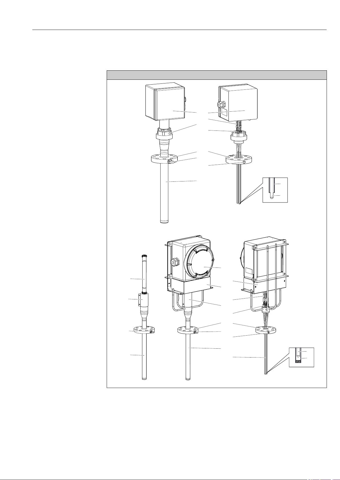
3.1 Equipment architecture
The multipoint thermometer belongs to a range of modular product configuration for
multipoint temperature detection with a design where subassemblies and components can
be managed individually for easy maintenance and spare part ordering.
It consists of the following main sub-assemblies:
• Insert: Composed by individual metal sheathed sensing elements (thermocouples or
thermos-resistance) protected by the primary thermowell welded to the process
connection. In addition, individual guiding tubes or protecting themowells allow inserts
replacement during operating conditions. When applicable, each insert can be handled
as an individual spare part and ordered via specific standard product order codes (e.g.
TSC310, TST310) or special codes. For the specific order code please contact your
Endress+Hauser specialist.
• Process Connection: Represented by an ASME or EN flange. It can be provided with
pressure port and it might be provided with eyebolts for lifting the device.
• Head: It is composed of a junction box provided with its components such as cable
glands, draining valves, earth screws, terminals, head transmitters, etc.
• Head Support Frame: It is designed to support the junction box. Two different types are
available:
• Direct mounted support frame
• Three pieces union joint
• Additional Accessories: They can be ordered for any configuration, and they are
recommended in case of replaceable sensors configuration (such as pressure
transducers, manifolds, valves and fitting).
• Primary Thermowell: It is directly welded to the process connection, designed to
guarantee high degree of mechanical protection and corrosion resistance.
8 Endress+Hauser
Page 9
iTHERM TMS11 MultiSens Linear Product description
1a
2b
4
11
7
8
9
3
6b
5
1a
2a
4
6a
9
7
8
3
10c
10b
11
6a
5
10b
10a
4
3
In general, the system measures a linear temperature profile inside the process
environment. It is also possible to obtain a three-dimensional temperature profile by
installing more than one Multisens Linear (either horizontally, vertically or obliquely).
Design
A0016673
A0036087
Endress+Hauser 9
Page 10

Product description iTHERM TMS11 MultiSens Linear
Description, available options and materials
1: Head
1a: Directly mounted
1b: Remote
2: Support System
2a: With rods and protection cover
2b: With three pieces union joint Support frame for intrinsically safe requirements.
3: Primary thermowell The primary thermowell is made by a tube with calculated and
4: Process connection, flanged
according to ASME, or EN standards
5: Insert Mineral insulated grounded and ungrounded thermocouples or RTD
6 Tip design of:
6a: protecting thermowells
6b: guiding tubes The sensors inside the primary thermowell can be kept in the right
7: Eyebolt Lifting device for easy handling during installation phase.
8: Extension cables Cables for electrical connections between the inserts and junction
Hinged or screwed cover junction box for electrical connections. It
includes components such as electrical terminals, transmitters and
cable glandes.
• 316/316L
• Aluminium alloys
• Other materials on request
Support frame for explosion proof requirements.
316/316L
316/316L
selected thickness according to reference international standards. It is
designed to protect the sensors against harsh process conditions such
as dynamic and static loads and corrosion.
It is composed of two main zones, one inside the process and the
other one outside of the process (thermowell head). The main
thermowell goes across the process connection and on the upper part
there are compression fitting to allow insert replacement (when
possible)
• 316/316L
• 321
• 304/304L
• 310L
Represented by a flange according to international standards, or
engineered to satisfy specific process requirements → 38.
• 316 + 316L
• 304/304L
• 310L
• 321
• Other materials on request
(Pt100 wire wound).
For details, refer to the Ordering information table
The sensors inside the primary thermowell can be kept in the right
measuring location by means of closed-end protecting thermowells
which end with:
• welded thermal block discs to ensure the optimal heat transfer
thorough the primary thermowell wall and the temperature
sensors. Sensors are replaceable.
• individual thermal blocks pressed against the internal wall to
ensure the optimal heat transfer between the primary thermowell
and the replaceable temperature sensor.
• straight tip.
For details, refer to the Ordering information table
measuring location by means of open-end guiding tubes which end
with:
• bimetallic stripes to push the sensor in contact with the internal
wall of the main thermowell and allow faster response time.
Sensors not replaceable.
• bent tip.
SS 316
box.
• Shielded PVC
• Shielded Hyflon MFA
• Unshielded PVC flying leads
10 Endress+Hauser
Page 11

iTHERM TMS11 MultiSens Linear Product description
Description, available options and materials
9: Optional connection (Pressure Port
threaded hole)
10: Protections
10a: Cable conduit system (in case of
remote head)
10b: Cable conduit cover
10c: Extension cable cover
11: Compression fitting High performing fittings for the tightness between the thermowell-
Auxiliary connections and fittings for pressure detection.
Cable conduit system: made by flexible polyamide to connect the top
of the primary thermowell and the remote junction box.
Cable conduit cover: composed of two half shields installed between
the top of the primary thermowell and the junction box.
Extension cable cover: made by a shaped stainless stell plate fixed to
the junction box frame in order to protect the cable connections.
head and the external environment, suitable for a wide range of
process fluids and severe combination between temperature and
pressure.
Endress+Hauser 11
Page 12
Incoming acceptance and product identification iTHERM TMS11 MultiSens Linear
Made in Italy 2018
20060 Pessano con Bornago-MI
iTHERM MultiSens Linear
Ser.no.: XXXXXXXXXXX
Ord.cd.: -XXXX/XXTMS11
2xPt100/TF/4Cl.A
no. of inserts: 12
TMT182-B
No of transmitter:12
Ref to BA01 T/09/en839
Measuring range: 0...250 °C
YYYY
PED information
5
6
7
TSV00XXXX-XXXXX
4 Incoming acceptance and product
identification
4.1 Incoming acceptance
Before proceeding with the installation the following incoming acceptance procedures are
suggested:
• Once the device is received it is always suggested to verify the integrity of the packaging
and possible damages. Non-compliances should be immediately reported to the
manufacturer. Damaged material shall not be installed: in these conditions, in fact, the
manufacturer cannot guarantee the original safety requirements and cannot be
considered responsible for any consequential effect.
• Compare the scope of delivery with the order content.
• Carefully remove all packaging/protection related to the freight.
4.2 Product identification
The following options are available for identification of the device:
• Nameplate specifications
• Enter the serial number from the nameplate in the W@M Device Viewer
(www.endress.com/deviceviewer): All data relating to the device and an overview of
the Technical Documentation supplied with the device are displayed.
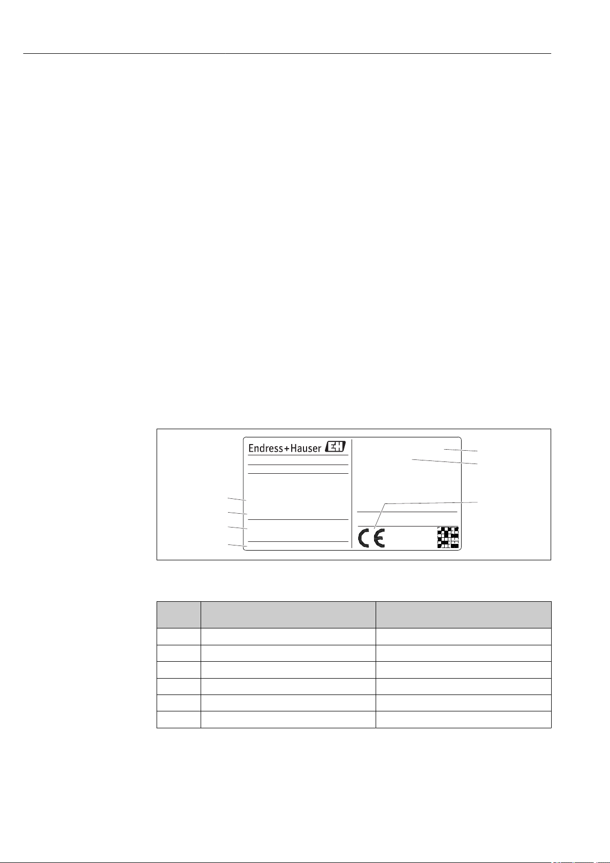
The following nameplate layout serves to identify the specific product information from
the serial number, design conditions, sizes, configuration to approvals:
1 Nameplate of the multipoint thermometer (example as landscape format)
Field
number
1 Order code and serial number TMS11-xxxxx
2 TSV drawing number TSV012345-XXXXX
3 Sensor and product configuration e.g. number of measuring points
4 Assembled transmitter -
5 Sensor measuring temperature range -
6 PED information (if applicable) e.g. volume, pressure, temperature
Description Examples
A0016719
12 Endress+Hauser
Page 13

iTHERM TMS11 MultiSens Linear Incoming acceptance and product identification
Field
number
7 CE marking (if applicable) -
- Approval number, hazardous area classification
Description Examples
e.g.–50 to 60 °C (–58 to 140 °F) for hazardous
and Ex logo (if applicable)
Safety instructions number (if applicable)
Ambient temperature (if hazardous area
classification is applicable)
area application
Compare and check the data on the nameplate of the device against the requirements
of the measurement enviroment.
4.3 Storage and transport
Carefully remove each package and protection relative to the transportation packaging.
NOTICE
Transportation of the device to the installation area.
Handle the device by always using the provided eyebolt as the main lifting part.
‣
Handle with care. During mounting phases avoid any load to welded or threaded parts,
‣
under the action of the weight of the device.
When the device has to pass from the horizontal to the vertical position or vice versa,
‣
particular attention must be taken.
It is strictly requested to avoid bumping against obstacles nearby the place where the
‣
device has to be installed.
Avoid any friction between the device and the other surrounding bodies.
‣
Pack the device in such a way as to protect it reliably against impact for storage and
transportation. The original packaging provides optimum protection.
For permitted storage temperature → 37
Endress+Hauser 13
Page 14

Mounting iTHERM TMS11 MultiSens Linear
5 Mounting
5.1 Mounting requirements
WARNING
L
Failure to follow these installation guidelines could result in death or serious injury
Make sure only qualified personnel perform the installation.
‣
WARNING
L
Explosions could result in death or serious injury
Before connecting any additional electric and electronic device in an explosive
‣
atmosphere, make sure the instruments in the loop are installed in accordance with
intrinsically safe or non incendive field wiring practices.
Verify that the operating atmosphere of the transmitters is consistent with the
‣
appropriate hazardous locations certifications.
All covers and threaded components must be fully engaged to meet explosion-proof
‣
requirements.
WARNING
L
Process leaks could result in death or serious injury
Do not release screwed parts while in operation. Install and tighten the fittings before
‣
applying pressure.
NOTICE
Additional loads and vibrations from other plant components can affect the operation
of the sensor elements.
Is it not allowed to apply additional loads or external moments to the system coming
‣
from the connection with another system not foreseen from installation plan.
The system is not suitable for being installed in locations where vibrations are present.
‣
The deriving loads can undermine the sealing of the junctions and damage the
operation of the sensing elements.
It will be care of the final user to verify the installation of suitable devices in order to
‣
avoid the overcoming of the admitted limits.
For the environment conditions please refer to the technical data → 37
‣
While installing the measurement system, avoid any friction, specifically avoid sparks
‣
generation.
When the installation is performed by using existing vessel internal infrastructures,
‣
ensure that any applied external loads (i.e. to the tip of the primary thermowell) don't
generate deformations and strains on the device and especially on welds.
5.2 Mounting the assembly
5.2.1 Mounting sequence
When installing the device, it is recommended to perform an internal inspection of the
vessel. Check if there is any obstacle, with the aim of making an easy insertion. While
installing the measurement system, avoid any friction during installation, specifically avoid
sparks generation.
14 Endress+Hauser
Page 15
iTHERM TMS11 MultiSens Linear Mounting
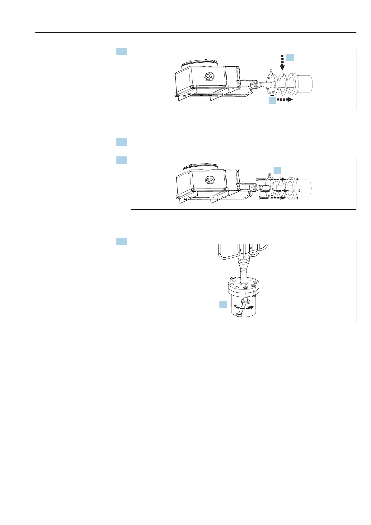
1.
2.
3.
4.
1.
A0036096
Place the gasket between the flanged nozzle and the flange of the device (after
checking the cleanliness of gasket seats on the flanges).
2. Bring the device to the nozzle, inserting the main thermowell through the nozzle
avoiding deformation.
3.
Start the bolts insertion through the flanges’ holes and tighten them with the nuts by
using a suitable wrench tool - but do not tighten them completely.
4.
Complete the bolts insertion through the flanges’ holes and tight them with the
crossed method by means of an appropriate equipment (i.e. controlled tensioning
according to the applicable standards).
A0036097
A0036533
Endress+Hauser 15
Page 16
Mounting iTHERM TMS11 MultiSens Linear
+
+
-
-
+
+
-
-
+
+
-
-
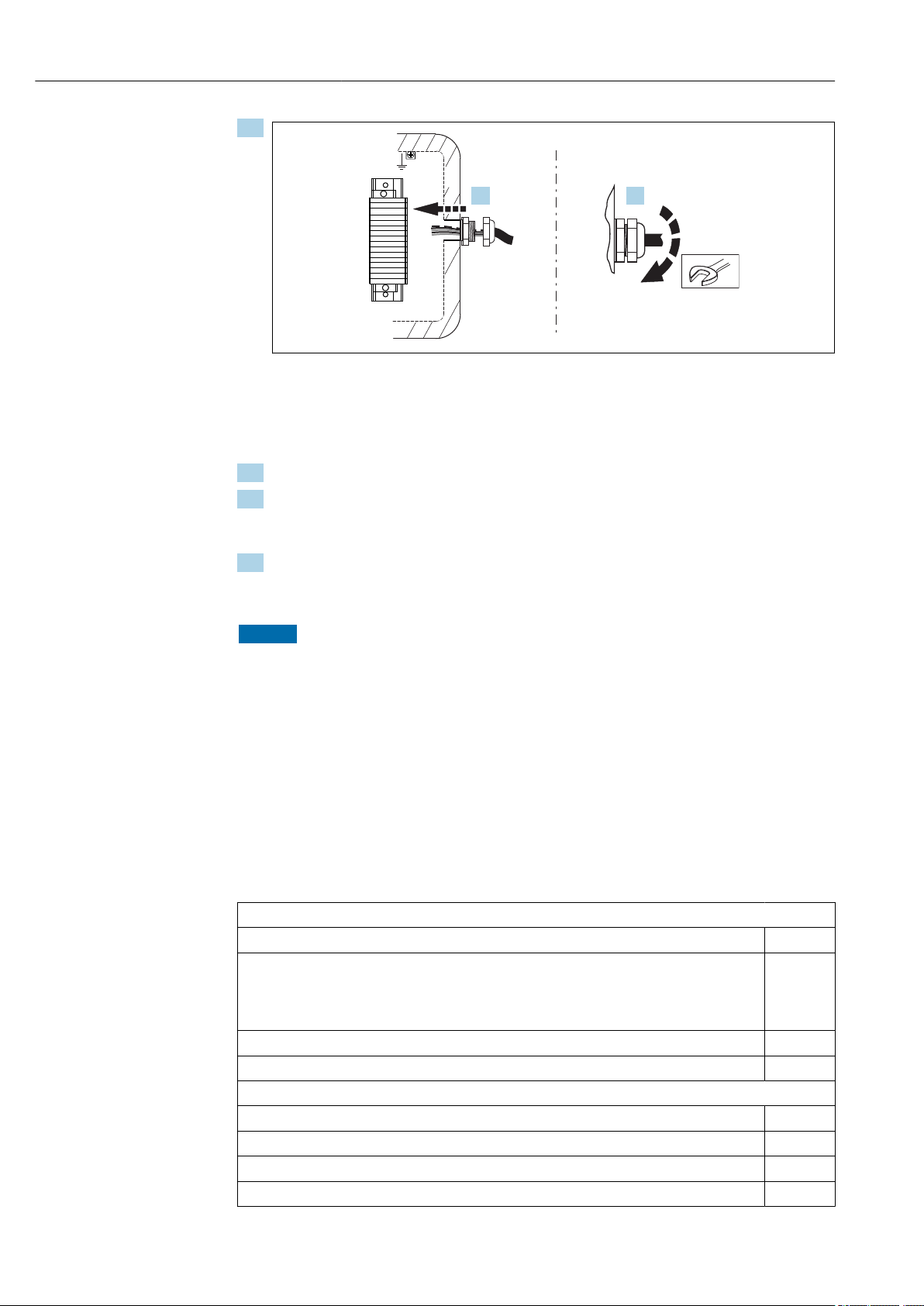
7. 8.
5.
A0028375
2 View from user side
To wire the system, after having opened the cover of the junction box introduce the
extension or compensating cables through the respective cable glands in the junction
box.
6. Tighten the cable glands on the junction box.
7. Connect the cables to the terminals or temperature transmitters of the junction box
following the wiring instruction provided, ensuring the right matching between the
cable tag numbers and the terminals tag numbers.
8. Close the cover ensuring the right gasket position to avoid any impact on the IP
degree of protection and set the draining valve in the right position (for humidity
condensation control).
NOTICE
After the mounting, perform few simple checks on the installed thermometric
system.
Check the tightness of the threaded connections. If any part is loosened, tight it
‣
applying the proper torque.
Check for correct wiring, test the electrical continuity of the thermocouples (warming
‣
up the thermocouple hot junction, when feasible) and then verify the absence of short
circuits.
5.3 Post-mounting check
Before commissioning the measuring system make sure that all final checks have been
carried out:
Device conditions and specifications
Is the device undamaged (visual inspection)?
Do the ambient conditions match the device specification?
For example:
• Ambient temperature
• Proper conditions
Are the threaded components undeformed?
Are the gaskets not permanently deformed?
Installation
Is the equipment aligned with the nozzle axis?
Are the gasket seats of flanges clean?
16 Endress+Hauser
Is the coupling between the flange and its counter flange reached?
Is the primary thermowell undeformed?
Page 17

iTHERM TMS11 MultiSens Linear Mounting
Are the bolts completely inserted in the flange? Make sure the flange is completely attached to
the nozzle.
Is the primary thermowell properly fixed to the internal infrastructures (when applicable)?
Are the cable glands tightened on the extension cables?
Are the extension cables connected to the junction box terminals?
Are the extension cable protections (when ordered) properly assembled and closed?
Endress+Hauser 17
Page 18
Wiring iTHERM TMS11 MultiSens Linear
6 Wiring
CAUTION
L
Failure to observe this may result in destruction of parts of the electronics.
Switch off power supply before installing or connecting the device.
‣
When installing devices in a hazardous area please take special note of the instructions
‣
and connection schematics in the respective Ex documentation added to these
Operating Instructions. The local Endress+Hauser representative is available for
assistance if required.
When wiring to a transmitter also observe the wiring instructions in the enclosed
Brief Operating manuals of the relevant transmitter.
For wiring the device proceed as follows:
1. Open the housing cover on the junction box.
2. Open the cable glands on the sides of the junction box.
3. Feed the cables through the opening in the cable glands.
4. Connect the cables as shown on
5. On completion of the wiring, screw the terminals tight. Tighten the cable glands
again. Close the housing cover.
6. In order to avoid connection errors always take note of the hints given in the post
connection check! → 22
6.1 Quick wiring guide
Terminal assignment
NOTICE
Destruction or malfunction of parts of the electronics through ESD - electrostatic
discharge.
Take measures to protect the terminals from electrostatic discharge.
‣
To avoid incorrect measuring values an extension or compensation cable for direct
wiring of thermocouple and RTD sensors for the signal transmission has to be used.
The polarity indication on the respective terminal block and the wiring scheme has to
be observed.
The planning and the installation of the bus connection cables of the plant is not to be
concerned of the manufacturer of the device. Therefore the manufacturer cannot be
considered to be responsible for possible damages due to the choice of materials that
are not suitable for that application or to a faulty installation.
18 Endress+Hauser
Page 19
iTHERM TMS11 MultiSens Linear Wiring
-
+
+
1
-
2
7
6
5
4
3
1
2
7
6
5
4
3
Sensor input 2
Sensor input 1
RTD 4- and 3-wire:
RTD 3-wire:
Bus connection
and supply voltage
Display connection
red
white
red red
red
whitewhite
TC
TC
3
5
6
RTD
3
4
5
6
RTD
1
2
TC
6
4
3-wire
4-wire
Power supply
head transmitter and
analog output 4 to 20 mA,
or bus connection
(red) (red)
(red) (red)
(white) (white)
(white)
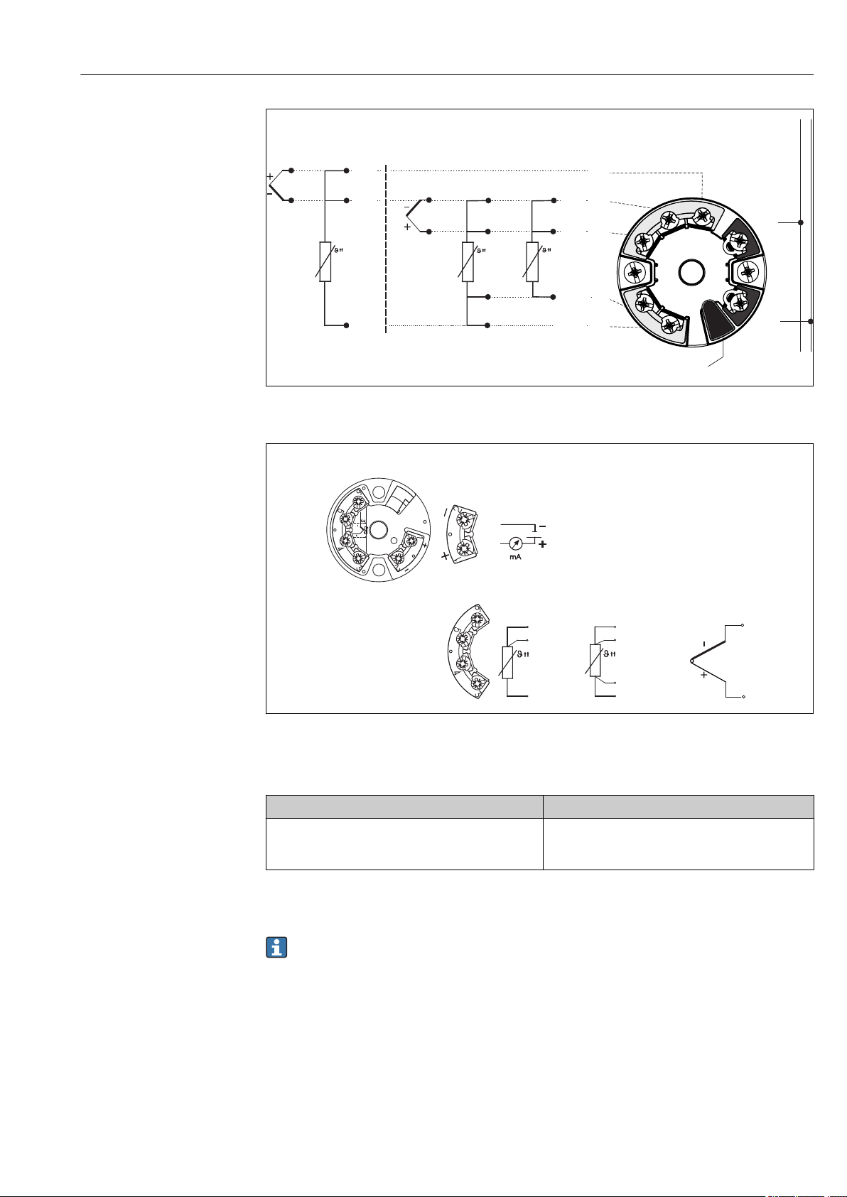
A0016711-EN
3 Wiring diagram of the dual sensor input head transmitters (TMT8x)
A0016712-EN
4 Wiring diagram of the single sensor input head transmitters (TMT18x)
Thermocouple cable colors
According to IEC 60584 According to ASTM E230
• Type J: Black (+), white (-)
• Type K: Green (+), white (-)
• Type N: Pink (+), white (-)
• Type J: White (+), red (-)
• Type K: Yellow (+), red (-)
• Type N: Orange (+), red (-)
6.2 Connecting the sensor cables
Each sensor is marked with an individual TAG number. As default configuration, all
Endress+Hauser 19
wires are always connected to the installed transmitters or terminals.
Page 20

Wiring iTHERM TMS11 MultiSens Linear
+
+
-
-
+
+
-
-
+
+
-
-
+
+
-
-
1B
1B
1A
1A
+
1
-
2
7
6
5
4
3
+
1
-
2
7
6
5
4
3
+
1
-
2
7
6
5
4
3
+
1
-
2
7
6
5
4
3
1B
1A
1A
1B
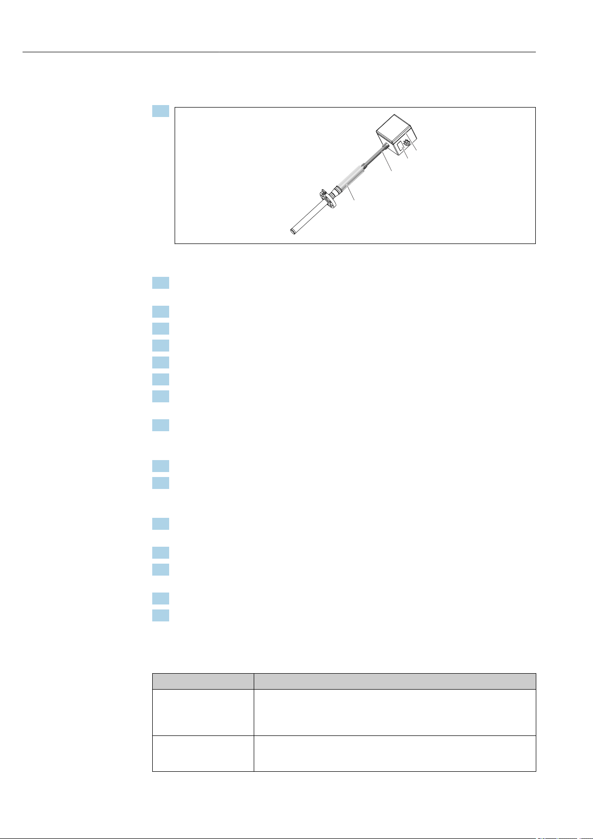
A0033288
5 Direct wiring on the mounted terminal block. Example for the internal sensor wires marking with 2 x TC
sensors in insert no. 1.
The wiring is done in consecutive order, which means that the input channel(s) of
transmitter no. 1 are connected to the insert wires starting from insert no. 1. Transmitter
no. 2 is not used until all channels of transmitter no. 1 are fully connected. The wires of
each insert are marked with consecutive numbers starting from 1. If double sensors are
used the internal marking has a suffix to distinguish the two sensors, e.g. 1A and 1B for
double sensors in the same insert or measuring point no. 1.
6 Mounted and wired head transmitter. Example for the internal sensor wires marking with 2 x TC
Sensor type Transmitter type Wiring rule
1 x RTD or TC • Single input (one channel)
• Double input (two channels)
• Multi-channel input (8 channel)
2 x RTD or TC • Single input (one channel)
• Double input (two channels)
• Multi-channel input (8 channel)
• 1 Head transmitter per insert
• 1 Head transmitter for 2 inserts
• 1 Multi-channel transmitter for 8 inserts
• Not available, wiring excluded
• 1 Head transmitter per insert
• 1 Multi-channel transmitter for 4 inserts
20 Endress+Hauser
A0033289
Page 21

iTHERM TMS11 MultiSens Linear Wiring
+
1
-
2
7
6
5
4
3
+
1
-
2
7
6
5
4
3
2
3
4
6.3 Connecting the power supply and signal cables
Cable specification
• A shielded cable is recommended for fieldbus communication. Take the plant grounding
concept into consideration.
• The terminals for connecting the signal cable (1+ and 2-) are protected against reverse
polarity.
• Conductor cross-section:
• Max 2.5 mm2 (14 AWG) for screw terminals
• Max 1.5 mm2 (16 AWG) for spring terminals
Always observe the general procedure on → 18.
A0033290
7 Connecting the signal cable and power supply to the installed transmitter
1 External ground terminal
2 Terminals for signal cable and power supply
3 Internal ground terminal
4 Shielded signal cable, recommended for fieldbus connection
6.4 Shielding and grounding
For any specific electrical shielding and grounding regarding the transmitter wiring
please refer to the appropriate operating manual of the installed transmitter.
Where applicable, national installation regulations and guidelines must be observed
during the installation! Where there are large differences in potential between the
individual grounding points, only one point of the shielding is connected directly with the
reference ground. In systems without potential equalization, therefore, cable shielding of
fieldbus systems should only be grounded on one side, for example at the supply unit or at
safety barriers.
NOTICE
If the shielding of the cable is grounded at more than one point in systems without
potential matching, power supply frequency equalizing currents can occur that
damage the signal cable or have a serious effect on signal transmission.
In such cases the shielding of the signal cable is to be grounded on only one side, i.e. it
‣
must not be connected to the ground terminal of the housing (terminal head, field
housing). The shield that is not connected should be insulated!
6.5 Degree of protection
The device is conform to the requirements up to IP 66 ingress protection. In order to fulfil
the degree of protection after installation or service, the following points must be taken
into consideration: → 8, 22
Endress+Hauser 21
Page 22

Wiring iTHERM TMS11 MultiSens Linear
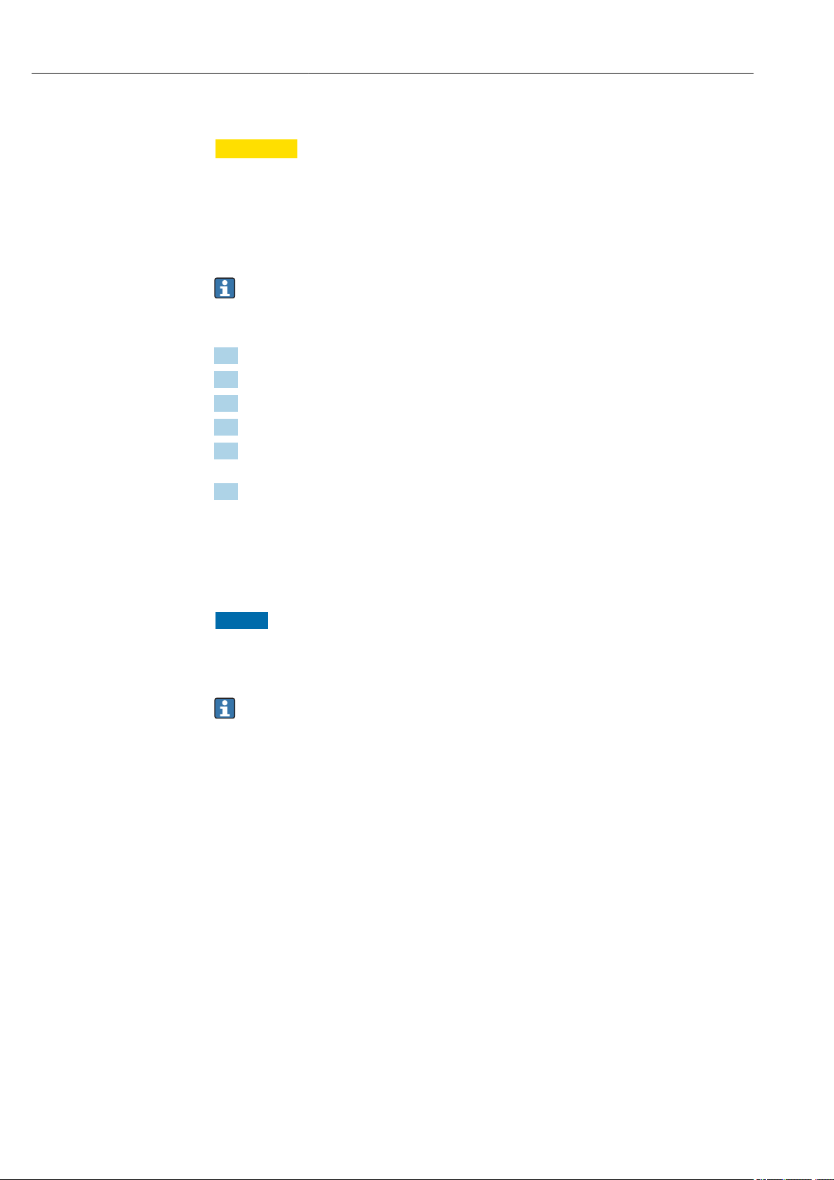
• The housing seals must be clean and undamaged before they are replaced in the sealing
rebate. If they are found to be too dry, they should be cleaned or even replaced.
• All housing screws and covers must be tightened.
• The cables used for connection must be of the correct specified outside diameter (e.g.
M20 x 1.5, cable diameter from 0.315 to 0.47 in; 8 to 12 mm).
• Tighten cable gland.
• Loop the cable or conduit before placing into the entry ("Water sack"). This means that
any moisture that may form cannot enter the gland. Install the device so that the cable
or conduit entries are not facing upwards.
• Entries not used are to be blanked off using the blanking plates provided.
• The protective grommet must not be removed from the NPT fitting.
8 Connection hints to maintain IP protection
6.6 Post-connection check
Is the device undamaged (internal equipment inspection)?
Electrical connection
Does the supply voltage match the specifications on the nameplate?
Do the cables have adequate strain relief?
Are the power supply and signal cables correctly connected? → 18
Are all the screw terminals well tightened and have the connections of the spring terminals been
checked?
Are all the cable glands installed, tightened and sealed?
Are all the housing covers installed and tightened?
Does the marking of the terminals and cables match?
Is the electrical continuity of the thermocouple verified?
A0011260
22 Endress+Hauser
Page 23

iTHERM TMS11 MultiSens Linear Commissioning
7 Commissioning
7.1 Preliminaries
Set-up guidelines of Standard, Extended and Advanced Commissioning for Endress
+Hauser instruments in order to guarantee the function of the instrument according to:
• Endress+Hauser operating manual
• Customer set up specification, and/or
• Application conditions, when applicable under process conditions
Both the operator and the person responsible for the process should be informed that a
commissioning job will be carried out, observing the following actions:
• If applicable, before disconnecting any sensor that is attached to the process, determine
what chemical or fluid is being measured (observe safety data sheet).
• Be aware of the temperature and pressure conditions.
• Never open a process fitting or loosen flange bolts before you have confirmed it is safe to
do so.
• Be sure not to disturb the process when disconnecting inputs/outputs or when
simulating signals.
• Ensure our tools, equipment and the customer process are protected from cross
contamination. Consider and plan necessary cleaning steps.
• When commissioning requires chemicals (e.g. as reagents for standard operation or for
cleaning purposes), always follow and observe the safety regulations.
7.1.1 Reference documents
• Endress+Hauser Standard Operating Procedure for Health and Safety (see
documentation code: BP01039H)
• Operating Manual of relevant tools and equipment to perform the commissioning job.
• Relevant Endress+Hauser Service Documentation (operating manual, work instructions,
service info, service manual, etc.).
• Calibration certificates of the quality relevant equipment if available.
• If applicable, safety data sheet.
• Customer specific documents (safety instructions, setup points, etc.).
7.1.2 Tools and equipment
Multimeter and instrument related configuration tools as necessary from the above
mentioned action list.
7.2 Function check
Before commissioning the device make sure that all final checks have been carried out
• "Post-mounting check” checklist
• “Post-connection check” checklist
The commissioning should be performed according to our commissioning segmentation
(Standard, Extended and Advanced).
7.2.1 Standard commissioning
Visual inspection of device
1. Check the instrument(s) for damage which may have been caused during transport/
shipping or mounting/wiring
2. Check that the installation is done according to the operating manual
Endress+Hauser 23
Page 24

Commissioning iTHERM TMS11 MultiSens Linear
3. Check that the wiring is done according to the operating manual and the local
regulations (e.g. grounding)
4. Check the dust/water tightness of the instrument(s)
5. Check safety precautions (e.g.. radiometric measurements)
6. Power up the instrument(s)
7. Check the alarm list if applicable
Environmental conditions
1. Check that the environmental conditions are appropriate for the instrument(s):
Ambient temperature, humidity (ingress protection IPxx), vibrations, hazardous
areas (Ex, Dust-Ex), RFI/EMC, sun protection, etc.
2. Check access to the instrument(s) for utilization and maintenance
Configuration parameters
Configure the instrument(s) according to the Operating Manual with the parameters
‣
specified by the customer or mentioned on the design specification
Output signal value check
Check and confirm that the local display and the output signals of the instrument(s)
‣
conform with the customer’s display
7.2.2 Extended commissioning
In addition to the steps of Standard Commissioning, the following should be additionally
completed:
Instrument Conformity
1. Check the received instrument(s) with the purchase order or design specification
including accessories, documentation and certificates
2. Check Software Version (e.g. application software such as “Batching”) when provided
3. Check that the documentation has the correct issue and version
Functional test
1. Test of the instrument outputs, including switching points, auxiliary inputs/outputs
with the internal or an external simulator (e.g. FieldCheck)
2. Compare the measuring data/results with a reference from the customer. (e.g.
laboratory result in case of an analyzer, weight scale in the case of a batching
application, etc.)
3. Adjust the instrument(s) if necessary and as described in the operating manual
7.2.3 Advanced commissioning
The Advanced Commissioning provides a loop test in addition to the steps covered in the
Standard and Extended Commissioning.
Loop test
1. Simulate a minimum of 3 output signals from the instrument(s) to the control room
2. Read out/note the simulated and indicated values and check for linearity
24 Endress+Hauser
Page 25

iTHERM TMS11 MultiSens Linear Diagnostics and troubleshooting
7.3 Switching on the device
Once the final checks have been successfully completed, it is time to switch on the supply
voltage. Afterwards the multipoint thermometer is operational. If there are Endress
+Hauser temperature transmitter in use, please refer to the enclosed Brief Operating
Instructions for commissioning.
8 Diagnostics and troubleshooting
8.1 General troubleshooting
For electronic, always start troubleshooting with the checklists available in the related
operating manuals. This takes you directly (via various queries) to the cause of the
problem and the appropriate remedial measures.
For the complete temperature device, please refer to the following instruction.
NOTICE
Repair of parts of the device
In the event of a serious fault, a measuring device might have to be replaced. In the
‣
case of replacement see section 'Return' → 31.
Before commissioning the measuring system make sure that all final checks have been
carried out:
• Follow the checklist in section 'Post-mounting check'→ 16
• Follow the checklist in section 'Post-connection check'
If transmitters are used, please refer to the documentation of the transmitter installed for
diagnostic and troubleshooting procedures → 48.
Endress+Hauser 25
Page 26

Maintenance and Repair iTHERM TMS11 MultiSens Linear
9 Maintenance and Repair
9.1 General notes
The accessibility around the device for maintenance has to be guaranteed. Each
component that is part of the device must be – in the case of replacement – replaced by an
original spare part of Endress+Hauser which guarantees the same characteristics and
performance. To ensure continued operational safety and reliability it is suggested to carry
out repairs on the device only if they are expressly permitted by Endress+Hauser,
observing federal/national regulations pertaining to repair of an electrical device.
9.2 Spare parts
Spare parts currently available for the product can be found online at
http://www.products.endress.com/spareparts_consumables.
When ordering spare parts, please specify the serial number of the unit!
Spare parts of the Multipoint thermometer assembly are:
• Complete junction box
• Temperature inserts (when applicable)
• Temperature transmitter
• Electric terminal
• DIN rail
• Plate for electric terminals
• Cable gland
• Sealing sleeve for cable gland
• Adapters for cable gland
• Junction box support system
The additional following accessories can be selected independently from the product
configuration:
• Pressure transmitter
• Pressure manometer
• Fitting
• Manifolds
• Valves
In case of replaceable inserts design the following steps have to followed.
NOTICE
Before starting any sensor replacement activity, it is mandatory to make sure that there
‣
is no pressure inside the primary thermowell, by checking the pressure value indicated
by the pressure accessories (manometer or pressure transmitter) mounted on the
pressure port.
In case of pressurized conditions, if only a pressure gauge/transmitter is installed, no
sensors replacement is allowed.
NOTICE
Please note that in case of pressure port absence, no direct maintenance on sensors is
‣
allowed, but only activities limited to the junction box components (cable glands,
transmitters, terminal blocks, etc.).
When a pressure gauge/transmitter is mounted in combination with manifods or multiways valves, then sensors can be replaced even in operating conditions after having
performed the here listed safety actions:
26 Endress+Hauser
Page 27

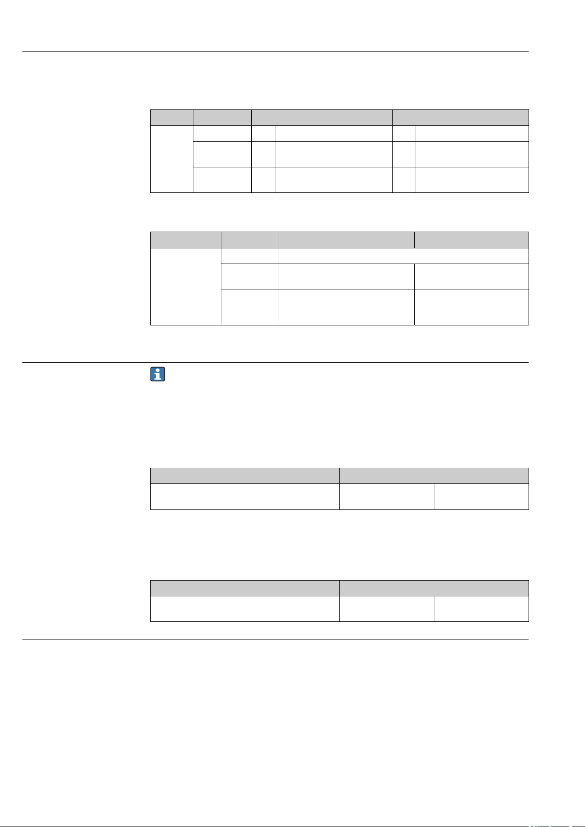
iTHERM TMS11 MultiSens Linear Maintenance and Repair
1 2 3 4 5 6
1.
A0036098
Switch the multi-way valve in drain position (when possible keeping pressure
indicator active).
2. Drain the fluids in a safe way to a blowdown line or by applying procedures in
compliance with the local safety regulations.
3. Make sure that all the over pressure is released.
4. Switch the multi-way valve in the original position in pressure detection mode.
5. Monitor the pressure indicator for a reasonable period time (depending on the
specific process conditions). Only when the pressure is not rising up again in a
significant way (between 20-30 minutes), start with the following operations:
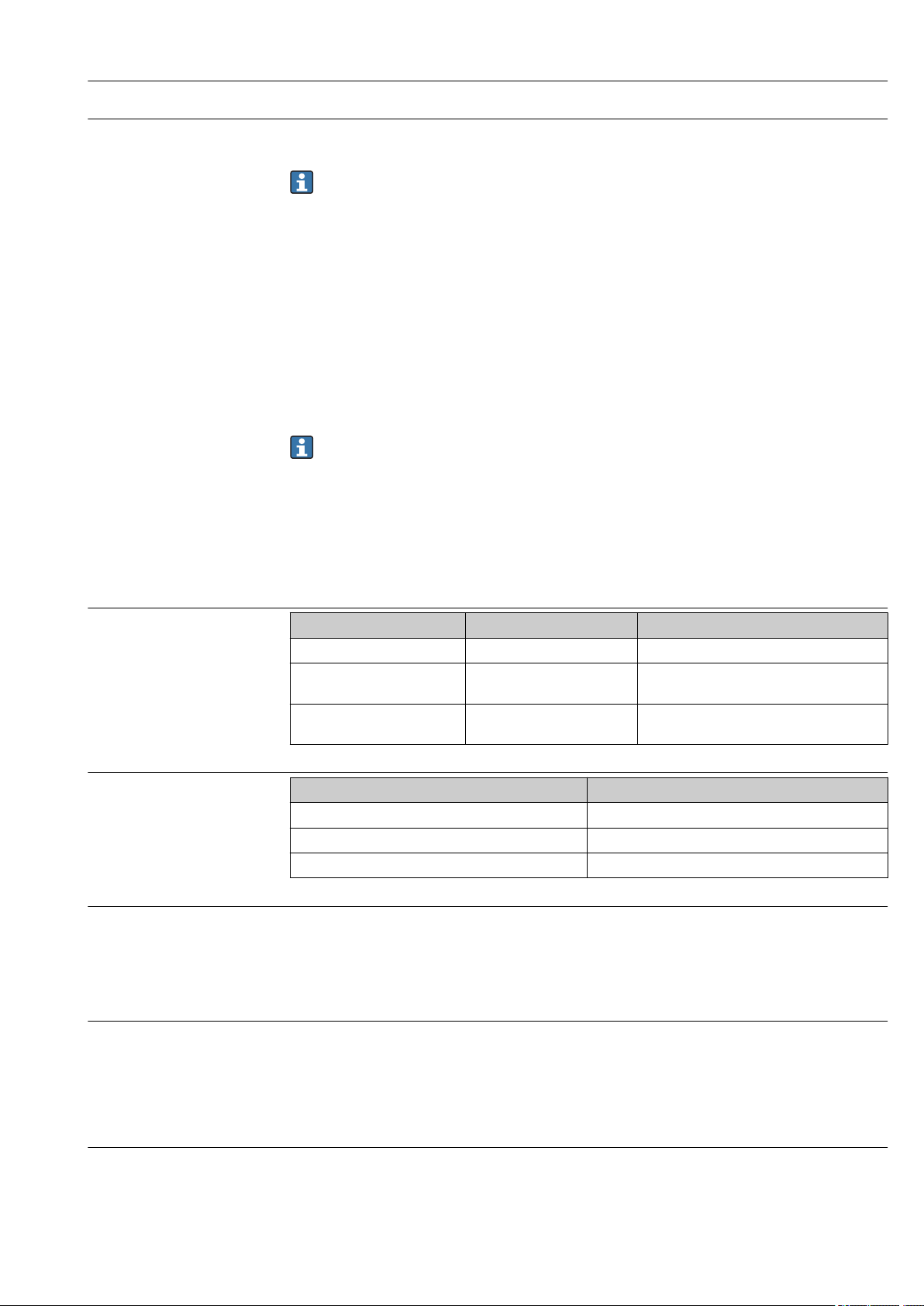
Case 1: Design with three pieces union joint (Instrinsically safe design)
1.
A0036099
Open the cover of the junction box (1).
2. Disconnect the sensor wires (3) of all the measuring inserts (6) from the terminal
block (2), or transmitter, inside the junction box (process side).
3. Unscrew completely the hexagonal nut of the three pieces union joint (5).
4. Remove apart the junction box with its adaptor (4) till the complete bundle of
sensors’ extension wires and the compression fittings are accessible.
5. Unscrew the compression fitting nuts.
6. Slip off carefully the sensors taking care not damaging the compression fitting
threads and sealing seats, slowly and completely.
7. Please note that the sealing metal ferrule of the unscrewed compression fitting must
be replaced at each of this operation. A new set of metal ferrules are required to have
the same specifications as the replaced part.
8. Lead in a new measuring insert through the compression fitting starting with the tip.
The length and specifications of the measuring insert to replace (by Endress+Hauser)
must meet the specifications of the replaced part.
9. Tight the nut of the compression fitting following the instructions of the
manufacturer.
10. If necessary clean the components of the three pieces union, taking care to avoid any
damages on its surface.
11. Reset the junction box in the original position and orientation taking care that the
extension cable bundle is completely inserted into the junction box.
Endress+Hauser 27
Page 28

Maintenance and Repair iTHERM TMS11 MultiSens Linear
1 2 3 4
5 6
12. Screw and tighten the hexagonal nut of the three pieces union joint.
13. Properly connect all cables of the measuring insert, according to wiring scheme, to
the relative terminal block or transmitter inside the junction box.
14. Close the housing cover.
Case 2: Design with direct mounted support frame (Explosion proof design)
1.
A0036100
Open the cover of the junction box (1).
2. Disconnect the sensor wires (3) of the measuring insert (4) that has to be replaced
(or the complete set in case of complete maintenance) from the terminal block (2) or
transmitter inside the junction box (process side).
3. Remove the cable gland protection plate (5).
4. Remove the extension cables cover (6).
5. Unloose the cable gland sealing nut of the targeted insert (or all) and slip off the
extension cables from the junction box.
6. Unscrew the compression fitting nuts.
7. Slip off carefully the sensor (or more sensors) taking care not damaging the
compression fitting threads and sealing seats, slowly and completely.
8. Please note that the sealing metal ferrule of the unscrewed compression fitting must
be replaced at each of this operation. A new set of metal ferrules are required to have
the same specifications as the replaced part.
9. Lead in a new measuring insert through the compression fitting starting with the tip.
The length and specifications of the measuring insert to replace (by Endress+Hauser)
must meet the specifications of the replaced part.
10. Insert the extension cables of the replaced sensor inside its cable gland.
11. Tight the nut of the compression fitting following the instructions of the
manufacturer.
12. Tight the cable gland sealing nut.
13. Properly connect all cables of the measuring insert, according to wiring scheme, to
the relative terminal block or transmitter inside the junction box.
14. Remount the cable gland protection plate and the extension cables cover.
15. Close the housing cover.
28 Endress+Hauser
Page 29

iTHERM TMS11 MultiSens Linear Maintenance and Repair
1
2
3
Case 3: Design with remote junction box and protecting conduit (Explosion proof
design)
1.
A0036101
Open the cover of the junction box (1).
2. Disconnect the sensor wires of all the measuring inserts that have to be replaced
from the terminal blocks or transmitters inside the junction box (process side).
3. Disjoint the extension cables cover (2) from the junction box.
4. Open the cable conduit cover (3).
5. Unloose the cable gland sealing nuts of all the inserts and slip off the extension
cables from the junction box.
6. Pullout the complete bundle of extension cables.
7. Remove completely the cable conduit covers.
8. Unscrew the compression fitting nuts.
9. Slip off carefully the sensor (or more sensors) taking care not damaging the
compression fitting threads and sealing seats, slowly and completely.
10. Please note that the sealing metal ferrule of the unscrewed compression fitting must
be replaced at each of this operation. A new set of metal ferrules are required to have
the same specifications as the replaced part.
11. Slide-in the new set bundle of extension cables in the conduit.
12. Lead in all the new measuring inserts through the compression fittings starting with
the tips. The length and specifications of each measuring insert to be replaced (by
Endress+Hauser) must meet the specifications of the replaced part.
13. Insert the different extension cables of the new sensors inside their cable glands.
14. Tight the nut of the compression fitting following the instructions of the
manufacturer.
15. Tight the cable gland sealing nut.
16. Properly connect all cables of the measuring insert, according to wiring scheme, to
the relative terminal block or transmitter inside the junction box.
17. Remount the extension cable cover and the cable conduit covers.
18. Close the housing cover.
Endress+Hauser 29
Page 30
Maintenance and Repair iTHERM TMS11 MultiSens Linear
3
2
4
1
Case 4: Design with remote junction box and protecting conduit (Intrinsically safe
design)
1.
A0036102
Open the cover of the junction box (1).
2. Disconnect the sensor wires of all the measuring inserts that have to be replaced
from the terminal blocks or transmitters inside the junction box (process side).
3. Unloose the cable conduit (2) from the junction box (3).
4. Open the extension cables cover (4).
5. Pullout the complete bundle of extension cables.
6. Remove completely the extension cable covers (4).
7. Unscrew the compression fitting nuts.
8. Slip off carefully the sensor (or more sensors) taking care not damaging the
compression fitting threads and sealing seats, slowly and completely.
9. Please note that the sealing metal ferrule of the unscrewed compression fitting must
be replaced at each of this operation. A new set of metal ferrules are required to have
the same specifications as the replaced part.
10. Slide-in the new set bundle of extension cables in the conduit.
11. Lead in all the new measuring inserts through the compression fittings starting with
the tips. The length and specifications of each measuring insert to be replaced (by
Endress+Hauser) must meet the specifications of the replaced part.
12. Tight the nut of the compression fitting following the instructions of the
manufacturer.
13. Tight the cable conduit (2) to the junction box.
14. Properly connect all cables of the measuring insert, according to wiring scheme, to
the relative terminal block or transmitter inside the junction box.
15. Remount the extension cables covers (4).
16. Close the housing cover.
9.3 Endress+Hauser services
Service Description
Certifications Endress+Hauser is able to fulfill requirements belonging to the design, product
manufacturing, tests and commissioning according to specific approvals by
handling or suppling individual certified components and by checking the
integration on the whole system.
Maintenance All Endress+Hauser systems are designed for an easy maintenance due to a
30 Endress+Hauser
modular design, allowing the replacement of old or wear out parts. Standardized
parts ensure fast reaction for maintenance.
Page 31

iTHERM TMS11 MultiSens Linear Maintenance and Repair
Service Description
Calibration Endress+Hauser’s range of calibration services covers on-site verification tests,
accredited laboratory calibrations, certificates and traceability to ensure
compliance.
Installation Endress+Hauser helps you commission plants while minimizing costs. Fault free
installation is decisive for the quality and longevity of the measurement system
and plant running. We provide the right expertise at the right time to meet
project deliverables.
Tests In order to ensure product quality and to guarantee efficiency during the entire
lifetime the following tests are available:
• Dye penetration test according to ASME V art. 6, UNI EN 571-1 and ASME VIII
Div. 1 App 8 standards
• PMI test accoding to ASTM E 572
• HE test according to EN 13185 / EN 1779
• X-ray test according to ASME V art. 2, art. 22 and ISO 17363-1 (requirements
and methods) and ASME VIII div. 1 and to ISO 5817 (acceptance criteria).
Thickness up to 30 mm
• Hydrostatic test according to PED Directive, EN 13445-5 and harmonized
• Ultrasonic test available by qualified external partners, according to ASME V
Art. 4.
9.4 Return
The measuring device must be returned if it is need of repair or a factory calibration, or if
the wrong measuring device has been delivered or ordered. Legal specifications require
Endress+Hauser, as an ISO-certified company, to follow certain procedures when handling
products that are in contact with the medium.
To ensure safe, swift and professional device returns, please refer to the procedure and
conditions for returning devices provided on the Endress+Hauser website at
http://www.endress.com/support/return-material
9.5 Disposal
9.5.1 Removing the measuring device
1. Switch off the device.
WARNING
L
Danger to persons from process conditions.
Beware of hazardous process conditions such as pressure in the measuring device, high
‣
temperatures or aggressive fluids.
2. Carry out the mounting and connection steps from the "Mounting the measuring
device" and "Connecting the measuring device" sections in reverse order. Observe the
safety instructions.
9.5.2 Disposing of the measuring device
WARNING
L
Danger to personnel and environment from fluids that are hazardous to health.
Ensure that the measuring device and all cavities are free of fluid residues that are
‣
hazardous to health or the environment, e.g. substances that have permeated into
crevices or diffused through plastic.
Observe the following notes during disposal:
Observe valid federal/national regulations.
‣
Ensure proper separation and reuse of the device components.
‣
Endress+Hauser 31
Page 32

Accessories iTHERM TMS11 MultiSens Linear
10 Accessories
Various accessories, which can be ordered with the device or subsequently from
Endress + Hauser, are available for the device. Detailed information on the order code is
available from your local Endress+Hauser sales center.
10.1 Device-specific accessories
Accessories Description
Tags Nameplate can be applied to identify each measuring
points and the whole assembly. Tags can be placed on
the extension cables in the extension area and/or in to
the junction box on individual wires or on other device.
Pressure transducer Digital or analogical pressure transmitter with welded
metal sensor for measurement in gases, steam or liquids.
Ref to Endress+Hauser PMP sensors family
Fitting, manifolds and valves are available for the
installation of the pressure transmitter on the pressure
port connection, and so allows the continuous
monitoring of the device under the operating conditions.
A0034865
Fitting / manifolds / valves
Composed by a polyamide cable conduit to connect the
top of the top of the thermowell and the remote junction
box, already provided of a shaped stainless steel cover
fixed to the junction box frame to protect the cable
connections.
A0036534
Remote cable conduit system
10.2 Communication-specific accessories
Configuration kit TXU10 Configuration kit for PC-programmable transmitter with setup software and
interface cable for PC with USB port
Order code: TXU10-xx
Commubox FXA195
HART
For intrinsically safe HART communication with FieldCare via the USB interface.
For details, see "Technical Information" TI00404F
32 Endress+Hauser
Page 33

iTHERM TMS11 MultiSens Linear Accessories
Commubox FXA291 Connects Endress+Hauser field devices with a CDI interface (= Endress+Hauser
Common Data Interface) and the USB port of a computer or laptop.
For details, see "Technical Information" TI00405C
HART Loop Converter
HMX50
Wireless HART adapter
SWA70
Fieldgate FXA320 Gateway for the remote monitoring of connected 4-20 mA measuring devices via a
Fieldgate FXA520 Gateway for the remote diagnostics and remote configuration of connected HART
Field Xpert SFX100 Compact, flexible and robust industry handheld terminal for remote configuration
Is used to evaluate and convert dynamic HART process variables to analog current
signals or limit values.
For details, see "Technical Information" TI00429F and Operating Instructions
BA00371F
Is used for the wireless connection of field devices.
The WirelessHART adapter can be easily integrated into field devices and existing
infrastructures, offers data protection and transmission safety and can be operated
in parallel with other wireless networks with minimum cabling complexity.
For details, see Operating Instructions BA061S
Web browser.
For details, see "Technical Information" TI00025S and Operating Instructions
BA00053S
measuring devices via a Web browser.
For details, see "Technical Information" TI00025S and Operating Instructions
BA00051S
and for obtaining measured values via the HART current output (4-20 mA).
For details, see Operating Instructions BA00060S
10.3 Service-specific accessories
Accessories Description
Applicator Software for selecting and sizing Endress+Hauser measuring devices:
• Calculation of all the necessary data for identifying the optimum measuring
device: e.g. pressure loss, accuracy or process connections.
• Graphic illustration of the calculation results
Administration, documentation and access to all project-related data and
parameters over the entire life cycle of a project.
Applicator is available:
• Via the Internet: https://portal.endress.com/webapp/applicator
• On CD-ROM for local PC installation.
W@M Life cycle management for your plant
W@M supports you with a wide range of software applications over the entire
process: from planning and procurement, to the installation, commissioning and
operation of the measuring devices. All the relevant device information, such as
the device status, spare parts and device-specific documentation, is available for
every device over the entire life cycle.
The application already contains the data of your Endress+Hauser device. Endress
+Hauser also takes care of maintaining and updating the data records.
W@M is available:
• Via the Internet: www.endress.com/lifecyclemanagement
• On CD-ROM for local PC installation.
FieldCare FDT-based plant asset management tool from Endress+Hauser.
It can configure all smart field units in your system and helps you manage them. By
using the status information, it is also a simple but effective way of checking their
status and condition.
For details, see Operating Instructions BA00027S and BA00059S
Endress+Hauser 33
Page 34

Technical data iTHERM TMS11 MultiSens Linear
11 Technical data
11.1 Input
Measured variable Temperature (temperature linear transmission behavior)
Measuring range RTD:
Input Designation Measuring range limits
RTD as per IEC 60751 Pt100 –200 to +600 °C (–328 to +1 112 °F)
Thermocouple:
Input Designation Measuring range limits
Thermocouples (TC) as per IEC
60584, part 1 - using an
Endress+Hauser - iTEMP
temperature head transmitter
Type J (Fe-CuNi)
Type K (NiCr-Ni)
Type N (NiCrSi-NiSi)
Internal cold junction (Pt100)
Cold junction accuracy: ± 1 K
Max. sensor resistance: 10 kΩ
–210 to +720 °C (–346 to +1 328 °F)
–270 to +1 150 °C (–454 to +2 102 °F)
–270 to +1 100 °C (–454 to +2 012 °F)
11.2 Output
Output signal Generally, the measured value can be transmitted in one of two ways:
• Directly-wired sensors - sensor measured values forwarded without a transmitter.
• Via all common protocols by selecting an appropriate Endress+Hauser iTEMP
temperature transmitter. All the transmitters listed below are mounted directly in the
junction box and wired with the sensory mechanism.
Family of temperature transmitters
Thermometers fitted with iTEMP transmitters are an installation-ready complete solution
to improve temperature measurement by significantly increasing accuracy and reliability,
when compared to direct wired sensors, as well as reducing both wiring and maintenance
costs.
PC programmable head transmitters
They offer a high degree of flexibility, thereby supporting universal application with low
inventory storage. The iTEMP transmitters can be configured quickly and easily at a PC.
Endress+Hauser offers free configuration software which can be downloaded from the
Endress+Hauser Website. More information can be found in the Technical Information.
HART® programmable head transmitters
The transmitter is a 2-wire device with one or two measuring inputs and one analog
output. The device not only transfers converted signals from resistance thermometers and
thermocouples, it also transfers resistance and voltage signals using HART
communication. It can be installed as an intrinsically safe apparatus in Zone 1 hazardous
areas and is used for instrumentation in the terminal head (flat face) as per DIN EN
50446. Swift and easy operation, visualization and maintenance by PC using operating
software, Simatic PDM or AMS. For more information, see the Technical Information.
®
PROFIBUS® PA head transmitters
Universally programmable head transmitter with PROFIBUS® PA communication.
Conversion of various input signals into digital output signals. High accuracy over the
complete ambient temperature range. Swift and easy operation, visualization and
34 Endress+Hauser
Page 35

iTHERM TMS11 MultiSens Linear Technical data
A
AA
-200 -100 0 100 200 300 400 500 600°C
0.5
1.0
1.5
2.0
B
2.5
3.0
- 0.5
- 1.0
- 1.5
- 2.0
- 2.5
- 3.0
B
A
AA
Max. deviation (°C)
Max. deviation (°C)
maintenance using a PC directly from the control panel, e. g. using operating software,
Simatic PDM or AMS. For more information, see the Technical Information.
FOUNDATION Fieldbus™ head transmitters
Universally programmable head transmitter with FOUNDATION Fieldbus™
communication. Conversion of various input signals into digital output signals. High
accuracy over the complete ambient temperature range. Swift and easy operation,
visualization and maintenance using a PC directly from the control panel, e.g. using
operating software such as ControlCare from Endress+Hauser or NI Configurator from
National Instruments. For more information, see the Technical Information.
Advantages of the iTEMP transmitters:
• Dual or single sensor input (optionally for certain transmitters)
• Unsurpassed reliability, accuracy and long-term stability in critical processes
• Mathematical functions
• Monitoring of the thermometer drift, sensor backup functionality, sensor diagnostic
functions
• Sensor-transmitter matching for dual sensor input transmitter, based on Callendar/Van
Dusen coefficients
11.3 Performance characteristics
Accuracy RTD resistance thermometer as per IEC 60751
Class Max. tolerances (°C) Characteristics
Cl. AA, former 1/3
Cl. B
Cl. A ± (0.15 + 0.002 · |t|
Cl. B ± (0.3 + 0.005 · |t|
Temperature ranges for compliance with the
tolerance classes
Wire wound
sensor (WW):
Thin-film version
(TF):
Standard –30 to +300 °C 0 to +150 °C
± (0.1 + 0.0017 · |t|
Cl. A Cl. AA
–100 to +450 °C –50 to +250 °C
Cl. A Cl. AA
1)
)
1)
)
1)
)
1) |t| = absolute value °C
In order to obtain the maximum tolerances in °F, the results in °C must be multiplied
by a factor of 1.8.
Endress+Hauser 35
A0008588-EN
Page 36
Technical data iTHERM TMS11 MultiSens Linear
Permissible deviation limits of thermoelectric voltages from the standard characteristic for
thermocouples as per IEC 60584 or ASTM E230/ANSI MC96.1:
Standard Type Standard tolerance Special tolerance
IEC 60584 Class Deviation Class Deviation
J (Fe-CuNi) 2 ±2.5 °C (–40 to 333 °C)
±0.0075 |t|
K (NiCr-NiAl)
N (NiCrSi-NiSi)
1) |t| = absolute value °C
Standard Type Standard tolerance Special tolerance
ASTM E230/ANSI
MC96.1
J (Fe-CuNi) ±2.2 K or ±0.0075 |t|
K (NiCr-NiAl)
N (NiCrSi-NiSi)
2 ±2.5 °C (–40 to 333 °C)
±0.0075 |t|
Deviation, the larger respective value applies
±2.2 K or ±0.02 |t|
±2.2 K or ±0.0075 |t|
(0 to 1 260 °C)
1)
(333 to 750 °C)
1)
(333 to 1 200 °C)
1)
(0 to 760 °C) ±1.1 K or ±0.004 |t|
1)
(–200 to 0 °C)
1)
1 ±1.5 °C (–40 to 375 °C)
±0.004 |t|
1 ±1.5 °C (–40 to 375 °C)
±0.004 |t|
(0 to 760 °C)
±1.1 K or ±0.004 |t|
(0 to 1 260 °C)
1)
(375 to 750 °C)
1)
(375 to 1 000 °C)
1)
1)
1) |t| = absolute value °C
Response time Response time for the sensor assembly without transmitter. When response time of
the complete assembly is requested (including primary thermowell), a dedicated
calculation depending on the sensor layout will be preformed.
RTD
Calculated at an ambient temperature of approx. 23 °C by immersing the insert in running
water (0.4 m/s flow rate, 10 K excess temperature):
Insert diameter Response time
As an example, in case of thermowell thickness,
3.6 mm (0.14 in), bent guiding tubes design
t
90
108 s
Thermocouple (TC)
Calculated at an ambient temperature of approx. 23 °C by immersing the insert in running
water (0.4 m/s flow rate, 10 K excess temperature):
Insert diameter Response time
As an example, in case of thermowell thickness,
3.6 mm (0.14 in), bent guiding tubes design
t
90
52 s
Shock and vibration resistance
• RTD: 3G / 10 to 500 Hz according to IEC 60751
• TC: 4G / 2 to 150 Hz according to IEC 60068-2-6
36 Endress+Hauser
Page 37
iTHERM TMS11 MultiSens Linear Technical data
Calibration Calibration is a service that can be performed on each individual insert, either in order
phase, or after multipoint installation (only in case of replaceable sensors).
When calibration shall be performed once the multipoint is installed, please contact
the Endress+Hauser service to get full support. Together with the Endress +Hauser
service any further activity can be organised to achieve the calibration of the target
sensor. In any case it is forbidden to unscrew any threaded component on the process
connection under operating conditions (running process), without knowing the
pressure inside the primary thermowell.
Calibration involves comparing the measured values of the sensing elements of the
multipoint inserts (DUT device under test) with those of a more precise calibration
standard using a defined and reproducible measurement method. The aim is to determine
the deviation of the DUT measured values from the true value of the measured variable.
Two different methods are used for the inserts:
• Calibration at fixed-point temperatures, e.g. at the freezing point of water at 0 °C (32 °F).
• Calibration compared against a precise reference thermometer.
Evaluation of inserts
If a calibration with an acceptable uncertainty of measurement and transferable
measurement results is not possible, Endress+Hauser offers an insert evaluation
measurement service, if technically feasible.
11.4 Environment
Ambient temperature range
Storage temperature
Humidity Condensation according to IEC 60068-2-33:
Junction box Non-hazardous area Hazardous area
Without mounted transmitter –50 to +85 °C (–58 to +185 °F) –50 to +60 °C (–58 to +140 °F)
With mounted head
transmitter
With mounted multi-channel
transmitter
Junction box
With head transmitter –50 to +100 °C (–58 to +212 °F)
With multi-channel transmitter –40 to +80 °C (–40 to +176 °F)
With DIN rail transmitter –40 to +100 °C (–40 to +212 °F)
–40 to +85 °C (–40 to +185 °F) Depends on the respective hazardous area
–40 to +85 °C (–40 to +185 °F) –40 to +70 °C (–40 to +158 °F)
• Head transmitter: Permitted
• DIN rail transmitter: Not permitted
Maximum relative humidity: 95% according to IEC 60068-2-30
approval. Details see Ex documentation.
Climate class Determined when the following components are installed into the junction box:
• Head transmitter: Class C1 according to EN 60654-1
• Multi-channel transmitter: Tested as per IEC 60068-2-30, meets the requirements
regarding class C1-C3 in accordance with IEC 60721-4-3
• Terminal blocks: Class B2 according to EN 60654-1
Electromagnetic compatibility (EMC)
Depending on the head transmitter used. For detailed information see the related
Technical Information, listed at the end of this document. → 48
Endress+Hauser 37
Page 38
Technical data iTHERM TMS11 MultiSens Linear
B
I
H
A
L
L
MPx
MPx
C
E
T
U
F
P
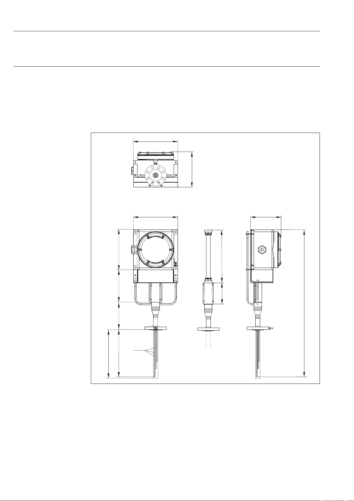
11.5 Mechanical construction
Design, dimensions The overall multipoint assembly is composed of different sub-assemblies. Different inserts
are available, based upon specific process conditions, in order to have the highest accuracy
and an extended lifetime. The primary thermowell should be selected to increase
mechanical performances and corrosion resistance. Associated shielded extension cables
are available with high resistance sheath materials to withstand different environmental
conditions and to ensure steady and noiseless signals. The transition between the inserts
and the extension cable is obtained by the usage of specially sealed bushings, ensuring the
declared IP degree protection.
9 Design of the modular multipoint thermometer, with frame neck. All dimensions in mm (in)
A, B,CDimensions of the junction box, see following figure
MPx Numbers and distribution of measuring points: MP1, MP2, MP3 etc.
L
Immersion length of sensing elements or protecting thermowells
MPx
I, H Encumbrance of the junction box and support system
38 Endress+Hauser
E Extension length
L Device length
T Lagging length
U Immersion length
P Protection: 250 mm
F Flexible hose length
A0036092
Page 39

iTHERM TMS11 MultiSens Linear Technical data
B
I
H
A
L
L
MPx
MPx
C
E
T
10 Design of the modular multipoint thermometer, with tube neck design. All dimensions in mm (in)
A, B,CDimensions of the junction box, see following figure
MPx Numbers and distribution of measuring points: MP1, MP2, MP3 etc.
L
Immersion length of sensing elements or protecting thermowells
MPx
I, H Encumbrance of the junction box and support system
E Extension length
L Device length
T Lagging length
U Immersion length
A0036093
Endress+Hauser 39
Page 40

Technical data iTHERM TMS11 MultiSens Linear
A
B
C
Junction box
A0028118
1 Cable glands
2 Junction box
3 Frame
The junction box is suited for chemical agents environments. Sea water corrosion
resistance and extreme temperature variation stability is guaranteed. Ex-e Ex-i terminals
can be installed.
Possible junction box dimensions (A x B x C) in mm (in):
A B C
150 (5.9) 150 (5.9) 100 (3.93)
200 (7.87) 200 (7.87) 160 (6.29)
270 (10.6) 270 (10.6) 160 (6.29)
270 (10.6) 350 (13.78) 160 (6.29)
350 (13.78) 350 (13.78) 160 (6.3)
350 (13.78) 500 (19.68) 160 (6.3)
500 (19.68) 500 (19.68) 160 (6.3)
280 (11.02) 305 (12) 228 (8.98)
420 (16.53) 420 (16.53) 285 (11.22)
332 (13.07) 332 (13.07) 178 (7)
330 (12.99) 495 (19.49) 171 (6.73)
Type of specification Junction box Cable glands
Material AISI 316 / Aluminium NiCr Plated brass
AISI 316 / 316L
Ingress protection (IP) IP66/67 IP66
Ambient temperature range –50 to +60 °C
(–58 to +140 °F)
Approvals ATEX approval for use in
hazardous area
–52 to +110 °C (–61.1 to +140 °F)
ATEX approval for use in hazardous area
40 Endress+Hauser
Page 41

iTHERM TMS11 MultiSens Linear Technical data
Type of specification Junction box Cable glands
Marking • ATEX II 2GD Ex e IIC/ Ex ia
Ga IIC Ex tb IIIC Db
T6/T5/T4
• IECEX II 2GD Ex e IIC/ Ex ia
Ga IIC Ex tb IIIC Db
T6/T5/T4
• IECEX II 2GD Ex e IIC/ Ex ia
Ga IIC Ex tb IIIC Db
T6/T5/T4
• ATEX II 2GD Ex d IIC T6T3/Ex tDA21 IP66 T85oCT200oC
• IECEX II 2GD Ex d IIC T6T3/ Ex tDA21 IP66 T85oCT200oC
• UL913 Class I, Division 1
Groups B, C, D T6/T5/T4
• FM3610 Class I, Division 1
Groups B, C, D T6/T5/T4
• CSA C22.2 No. 157 Class I,
Division 1 Groups B, C, D
T6/T5/T4
Cover Hinged and threaded -
Maximum sealing diameter - 6 to 12 mm (0.24 to 0.47 in)
→ 42
Support system
A modular system or a union joint is foreseen in case of direct mounted junction box.
It ensures the connection between the head of the primary thermowell and the junction
box. The system design ensures easy access for monitoring and maintaining inserts and
extension cables. Rods and protection cover guarantee a high stiffness connection for the
junction box and vibration loads. No closed volumes are present in the frame design
although it allows protection to the cables. This avoids the accumulation of waste and
potentially dangerous fluids coming from the environment that can damage the
instrumentation allowing continuous ventilation.
In case of three pieces union joint design the junction box can be orientated and the
extension cables remain accessible thanks to the disassembling of the joint.
Inserts, guiding tubes and protecting thermowells
Thermocouple
Diameter in mm (in) Type Standard Hot junction type Sheath material
1x type K
2x type K
3 (0.12)
1x type J
2x type J
1x type N
2x type N
IEC 60584 /ASTM
E230
Grounded/Ungrounded
Alloy600 / AISI 316L /
Pyrosil
Conductor thickness
Sensor Type Diameter in mm
(in)
Single Thermocouple 3 mm (0.11 in) Standard 0.3 mm (0.01 in) 0,45 mm = 25 AWG
Double Thermocouple 3 mm (0.11 in) Standard 0.27 mm (0.01 in) 0,33 mm = 28 AWG
Wall Min. Sheath
Thickness (S)
Min. Conductors Diameter
(C)
Endress+Hauser 41
Page 42
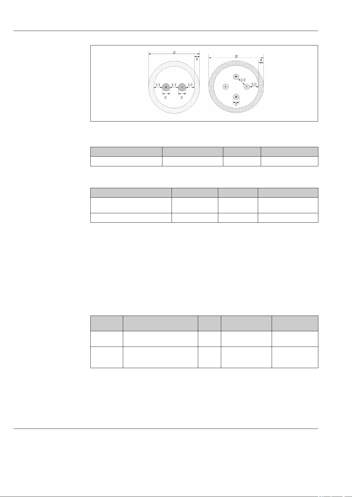
Technical data iTHERM TMS11 MultiSens Linear
A0035318
RTD
Diameter in mm (in) Type Standard Sheath material
3 (0.12) 1x Pt100 WW/TF IEC 60751 AISI 316L
Protecting thermowells or guiding tubes
External diameter in mm (in) Sheath material Type Thickness in mm (in)
6 (0.24) AISI 316L
8 (0.32) AISI 316L closed or open 1 (0.04)
closed or open 0.5 (0.02) or
1 (0.04)
Sealing components
The sealing components (compression fittings) are welded on the thermowell head to
guarantee proper tightness under all the foreseen operating conditions and to allow the
maintenance/replacement of the sensors (when applicable).
Material: AISI 316/AISI 316H
Cable Glands
Installed cable glands provide the proper level of reliability under the mentioned ambient
and operating conditions.
Material Marking IP
NiCr Plated
brass
AISI 316/AISI
316L
Atex II 2/3 GD Ex d IIC, Ex e II, Ex
nR II, Ex tD A21 IP66
Atex II 2G, II 1D, Ex d IIC Gb, Ex e
IIC Gb, Ex ta IIIC Da, II 3G Ex nR IIC
Gc
Rating
IP66 –52 to +110 °C
IP66 –52 to +110 °C
Ambient T range Max. sealing
diameter
6 to 12 mm
(–61.6 to +230 °F)
(–61.6 to +230 °F)
(0.23 to 0.47 in)
6 to 12 mm
(0.23 to 0.47 in)
Diagnostic function
The reactors where the multipoint assembly operates are usually characterized by severe
conditions in terms of pressure, temperature, corrosion and dynamics of the process fluids.
Thanks to the pressure port, it is possible to detect and monitor possible leakages (or gases
permeation) occurring through the primary thermowell, and plan the maintenance.
Weight The weight can vary based upon the configuration, depending on the junction box and the
frame design. The approximate weight of a typically configured multipoint thermometer
(number of inserts = 12, main body = 3", medium size junction box) = 30 kg (66.1 lb).
42 Endress+Hauser
Page 43

iTHERM TMS11 MultiSens Linear Technical data
The eyebolt, which is part of the process connection, must be used as the only lifting
component to move the entire device.
Materials The listed material properties have to be taken into account when selected for wetted
parts:
Material
name
AISI
316/1.4401
AISI 316L/
1.4404
1.4435
INCONEL®
600 / 2.4816
AISI
304/1.4301
AISI 316Ti/
1.4571
Short form Recommended
max.
temperature for
continuous use
in air
X2CrNiMo17-12-2 650 °C (1 202 °F) • Austenitic, stainless steel
X2CrNiMo17-12-2
X2CrNiMo18-14-3
NiCr15Fe 1 100 °C
X5CrNi18-10 850 °C (1 562 °F) • Austenitic, stainless steel
X6CrNiMoTi17-12-2 700 °C (1 292 °F) • Properties comparable to AISI316L.
650 °C (1 202 °F) • Austenitic, stainless steel
(2 012 °F)
Properties
• High corrosion resistance in general
• Particularly high corrosion resistance in chlorinebased and acidic, non-oxidizing atmospheres
through the addition of molybdenum (e.g.
phosphoric and sulfuric acids, acetic and tartaric
acids with a low concentration)
• High corrosion resistance in general
• Particularly high corrosion resistance in chlorinebased and acidic, non-oxidizing atmospheres
through the addition of molybdenum (e.g.
phosphoric and sulfuric acids, acetic and tartaric
acids with a low concentration)
• Increased resistance to intergranular corrosion
and pitting
• Compared to 1.4404, 1.4435 has even higher
corrosion resistance and a lower delta ferrite
content
• A nickel/chromium alloy with very good
resistance to aggressive, oxidizing and reducing
atmospheres, even at high temperatures.
• Resistant to corrosion caused by chlorine gas and
chlorinated media as well as many oxidizing
mineral and organic acids, sea water etc.
• Corrosion from ultrapure water.
• Not to be used in a sulfur-containing atmosphere.
• Well usable in water and lowly pollute waste
water
• Only at relatively low temperatures resistant to
organic acids, saline solutions, sulphates, alkaline
solutions, etc.
• Addition of titanium means increased resistance
to intergranular corrosion even after welding
• Broad range of uses in the chemical,
petrochemical and oil industries as well as in coal
chemistry
• Can only be polished to a limited extent, titanium
streaks can form
Endress+Hauser 43
Page 44

Technical data iTHERM TMS11 MultiSens Linear
2
1
1
2
3
Process connection
Material
name
AISI
321/1.4541
AISI
347/1.4550
Short form Recommended
max.
temperature for
continuous use
in air
X6CrNiTi18-10 815 °C (1 499 °F) • Austenitic stainless steel
X6CrNiNb10-10 800 °C (1 472 °F) • Austenitic stainless steel
Properties
• High resistance to intergranular corrosion even
after welding
• Good welding characteristics, suitable to all
standard welding methods
• It is used in many sectors of the chemical
industry, petrochemical, and pressurized vessels
• Good resistance to a wide variety of
environments in the chemical, textile, oilrefining, dairy and food industries
• Added niobium makes this steel impervious to
intergranular corrosion
• Good weldability
• Main applications are furnace fire walls, pressure
vessels, welded structures, turbine blades
11 Flange as process connection
1 Flange
2 Eyebolt
3 Pressure port
4 Compression fittings
Standard process connection flanges are designed according to the following standards:
Standard
ASME 1 1/2”, 2", 3” 150#, 300#, 400#, 600#, 900# AISI 316/L, 304/L, 310L, 321
EN DN40, DN50, DN80 PN10, PN16, PN25, PN 40, PN
1) Flanges according to GOST standard are available on request.
1)
Size Rating Material
63, PN100, PN150
316/1.4401, 316L/1.4404, 321/1.4541,
310L/1.4845, 304/1.4301, 304L/
1.4307
Compression fittings The compression fittings are welded onto the thermowell head to ensure the sensors
replacement(when applicable). Dimensions are coherent with the insert dimensions.
Compression fittings comply with the highest standards of reliability in terms of materials
and performances required
A0036094
44 Endress+Hauser
Page 45

iTHERM TMS11 MultiSens Linear Technical data
1
3
2
5
4
1
2
3
1
3
2
2
4
Material AISI 316/316H
Thermal contact components
A: Thermal contact block
1 Guiding tube
2 Spacer
3 Insert
4 Thermal block
5 Primary thermowell wall
B: Bent guiding tubes and spacers
The thermal blocks are forced against the
internal wall to ensure the optimal heat
transfer between the primary thermowell and
the replaceable temperature sensor
A0036153
• Allow sensor replacement
• Guarantee thermal contact between the
sensor tip and the existing thermowell
A0028783
1 Spacer
2 Guiding tube
3 Insert
C: Protecting thermowells and spacers
1 Protection thermowell
2 Spacer
3 Insert
4 Primary thermowell wall
Each sensor is protected by its protecting
thermowell with straight tip
A0036632
Endress+Hauser 45
Page 46

Technical data iTHERM TMS11 MultiSens Linear
3
2
6
5
4
7
1
8
1
2
3
D: Thermal block disc (welded to the primary thermowell)
1 Primary thermowell wall
2 Spacer
3 Guiding tube
4 Insert
5 Welded contact
6 Thermal block disc
7 Welding seam
8 Supporting rod
E: Bimetallic stripes
• Ensure the optimal heat transfer thorough
the primary thermowell wall and the
temperature sensors. Sensors are
replaceable
• Sensors can be replaced
A0036155
• Doesn't allow sensor replacement
• Guarantee thermal contact between the
sensor tip and the thermowell due to
bimetallic stripes activated by temperature
difference
• No friction during installation even with
already installed sensors
12 Bimetal strips with or without guiding tubes
1 Guiding tube
2 Insert
3 Bimetallic stripe
A0028435
46 Endress+Hauser
Page 47

iTHERM TMS11 MultiSens Linear Technical data
11.6 Certificates and approvals
CE Mark The complete assembly is provided with individual components CE marked, to ensure safe
use in hazardous areas and pressurized environments.
Hazardous area approvals The Ex approval applies to individual components like junction box, cable glands,
terminals. For further details on the available Ex versions (ATEX, UL, FM, CSA, IEC-EX,
NEPSI, EAC-EX), please contact your nearest Endress+Hauser sales organization. All
relevant data for hazardous areas can be found in separate Ex documentation.
ATEX Ex ia inserts are available only for diameters ≥ 1.5 mm (0.6 in). For further details
contact an Endress+Hauser technician.
PED approval The thermometer assembly can be provided with PED approval if required as the European
Directive 2014/68/UE says. Calculation reports, testing procedures, certificates , are
provided according the required calculation code and as foreseen in the product technical
dossier.
Certification HART The HART® temperature transmitter is registered by the FieldComm Group. The device
meets the requirements of the HART® Communication Protocol Specifications.
Certification FOUNDATION Fieldbus
Certification PROFIBUS® PA
The FOUNDATION Fieldbus™ temperature transmitter has successfully passed all test
procedures and is certified and registered by the Fieldbus Foundation. The device thus
meets all the requirements of the following specification:
• Certified according to FOUNDATION Fieldbus™ specification
• FOUNDATION Fieldbus™ H1
• Interoperability Test Kit (ITK), up to date revision status (device certification no.
available on request): the device can also be operated with certified devices of other
manufacturers
• Physical layer conformance test of the FOUNDATION Fieldbus™
The PROFIBUS® PA temperature transmitter is certified and registered by the PNO
(PROFIBUS® Nutzerorganisation e. V.), PROFIBUS user organization. The device meets all
the requirements of the following specifications:
• Certified according to FOUNDATION Fieldbus™ specification
• Certified in accordance with PROFIBUS® PA Profile (the up to date profile version is
available on request)
• The device can also be operated with certified devices of other manufacturers
(interoperability)
Other standards and guidelines
Material certification The material certificate 3.1 (according to standard EN 10204) can be requested separately.
Endress+Hauser 47
• IEC 61326-1:2007: Electromagnetic compatibility (EMC requirements)
• IEC 60529: Degree of protection of housing (IP code)
• IEC 60584 and ASTM E230/ANSI MC96.1: Thermocouples
• ASME B16.5, B16.36, EN 1092-1, GOST 12820-20: Flange
The certificate includes a declaration related to the materials used in the construction of
the single sensor and guarantees the traceability of the materials through the
identification number of the multipoint. The data related to the origin of the materials can
subsequently be requested by the client if necessary.
Page 48

Technical data iTHERM TMS11 MultiSens Linear
Test report and calibration The "Factory calibration" is carried out according to an internal procedure in a laboratory of
Endress+Hauser accredited by the European Accreditation Organization (EA) to ISO/IEC
17025. A calibration which is performed according to EA guidelines (SIT/Accredia) or
(DKD/DAkkS) may be requested separately. The calibration is performed on the inserts of
the multipoint.
11.7 Documentation
This guide is referred to the complete assembly. To have a complete overview of the
technical and operative instructions of the parts refer to the other documents of the
individual components manufactured by Endress+Hauser:
• Technical Information iTEMP temperature transmitters:
• HART® TMT82, two-channel, RTD, TC, Ω, mV (TI01010TEN_1715)
• HART® TMT182, two-channel, RTD, TC, Ω, mV (TI078ren_1310)
• TMT181, PC-programmable, single-channel, RTD, TC, Ω, mV (ti070ren)
• PROFIBUS® PA TMT84, two-channel, RTD, TC, Ω, mV (TI00138ren_0412)
• FOUNDATION FieldbusTM TMT85, two-channel, RTD, TC, Ω, mV (TI00134REN_0313)
• FOUNDATION FieldbusTM TMT125, 8 channel, RTD, TC, Ω, mV (TI00131ren_0111)
• Technical Information of inserts:
Thermocouple thermometer iTHERM TSC310 (TI00255ten_0111)
• Technical Information of pressure transmitter:
CERABAR S PMP71 (TI00451PEN_0111)
48 Endress+Hauser
Page 49

Page 50

Page 51

Page 52

www.addresses.endress.com
 Loading...