

Endress+Hauser TMR35 Specifications
TI00123R/09/EN/18.18
71425038
Products Solutions Services
Technical information
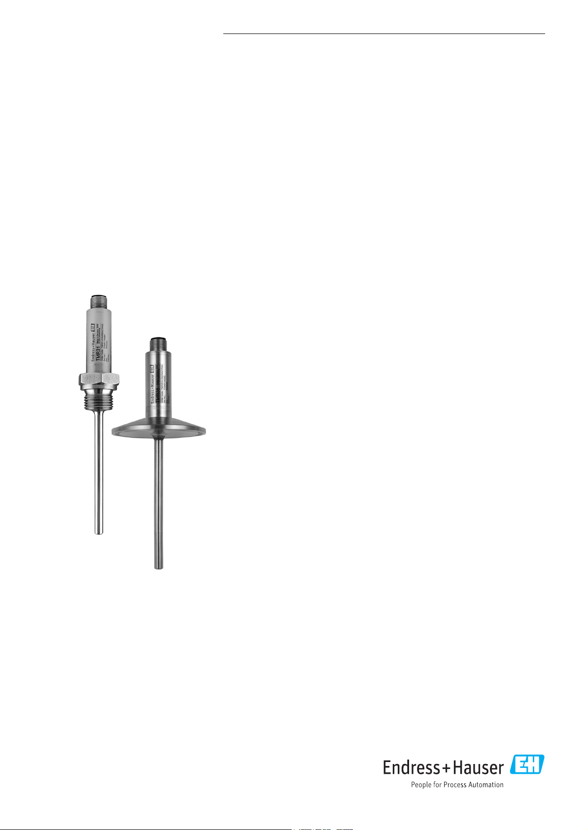
Easytemp TMR31, TMR35
Compact thermometer, Pt100, Class A
Optionally with integrated 4 to 20 mA
transmitter, programmable via PC
Application
The Easytemp TMR31 and TMR35 compact thermometers are used to measure
temperatures from -50 °C to 150 °C (-58 °F to 302 °F), or up to 200 °C (392 °F) with
neck. The most common installation locations are tanks and pipes.
• TMR31 with process connections for general applications.
• TMR35 with process connections for hygienic applications.
Benefits at a glance
Quick installation and easy commissioning:
• Small, compact design made entirely of stainless steel
• M12 connector with IP69K for an easy electrical connection
• 4-wire, Pt100 or PC-programmable transmitter with 4 to 20 mA output
• Configuration and visualization with ReadWin 2000 PC operating software,
which is free of charge
• Preset measuring range is available for order
• Variable insertion lengths from 40 mm to 600 mm (1.6 to 23.6 in)
Outstanding metrological properties thanks to innovative sensor technology:
• Extremely short response times
• Highly accurate even with short insertion lengths
• Thin film sensor element Pt100, accuracy class A (IEC 60751)
Safe operation with approvals and certificates:
• UL recognized component
• Meets all EMC requirements according to NAMUR NE21
• Breakdown information in event of sensor break or sensor short-circuit, adjustable
as per NAMUR NE43
• TMR35: Hygienic compatible design with 3-A marking and EHEDG certification
• Marine approval
TMR31, TMR35
ENDRESS+HAUSER
RN 221 N
Function and system design
Measuring principle Electronic recording and conversion of Pt100 input signals in industrial temperature measurement.
Measuring system The compact thermometer uses a Pt100 (Class A) sensor element for measurement. The device is
available with a Pt100 4-wire connection or, optionally, with an analog, temperature-linear 4 to 20
mA output signal. A built-in transmitter in the device converts the Pt100 input signal into the 4 to 20
mA signal and can be programmed using a PC via the M12 connector. The compact thermometer has
different process connections for general (TMR31) and hygienic applications (TMR35).
The Easytemp TMR31, TMR35 has a new kind of thin film sensor element that is soldered directly into
the sensor tip. This innovative sensor design ensures ideal heat transfer from the process to the sensor
element. This means that extremely fast response times and high levels of accuracy can be achieved
even with short insertion lengths.
1 IN 2
3 OUT 4
HAW562
HAW562
ENDRESS+HAUSER
Ecograph T
RN 221 N
RN221 N
3 OUT 4
HAW562
HAW562
1 IN 2
TMR31
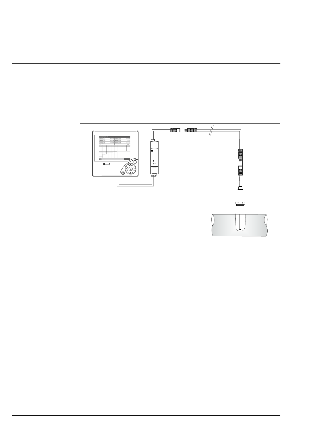
Measuring point layout (example) for Easytemp compact thermometer TMR31 with additional Endress+Hauser components
Ecograph T, active barrier RN221 N and HAW562 surge arrester
A0006994
Multi Channel Recorder Ecograph T
Multi-channel recorder Ecograph T in 144 x 144 mm (5.7 x 5.7 in) panel-mounted housing for the
electronic detection, display, recording, analysis, remote transmission and archiving of analog and
digital input signals. Data recording system on CompactFlash card, multi-colored LCD display, 120 mm
(4.72 in) screen size. Configuration and measured value display via interfaces (USB, Ethernet, RS232/
485) and ReadWin 2000 PC operating software.
Active barrier RN221 N
Active barrier with power supply for the safe separation of 4 to 20 mA standard signal circuits with
optional intrinsically safe input. The current applied by the transmitter of the compact thermometer in
the input circuit (4 to 20 mA) is transmitted linearly to the output.
Surge arrester HAW562
Protects consumer installations or measuring devices as well as signal lines and components against
overvoltage which is induced by lightning striking in the distance or through switching operations. The
HAW562 module acts as an overvoltage protection system in terminal block systems to protect signal
lines and components and is installed on a module carrier (HAW560).
2 Endress+Hauser
TMR31, TMR35
Input
Measuring principle Temperature (temperature-linear transmission behavior)
Measuring range
Designation Measuring range limits Min. span
Pt100 as per IEC 60751 -50 to 150 °C (-58 to 302 °F) without neck
Output
Output signal • Standard: Pt100, Class A, 4-wire
• Optional: 4 to 20 mA or 20 to 4 mA
Signal on alarm Signal on alarm as per NAMUR NE43
• Underranging: Linear drop to 3.8 mA
• Overranging: Linear rise to 20.5 mA
• Sensor break; sensor short-circuit:
3.6 mA or 21.0 mA (at settings 21.0 mA, 21.5 mA output is guaranteed)
Maximum load (U
power supply
Min. current consumption 3.5 mA
Current limit 23 mA
Switch-on delay 2 s
- 10 V) / 0.023 A (current output)
10 K (18 °F)
-50 to 200 °C (-58 to 392 °F) with neck
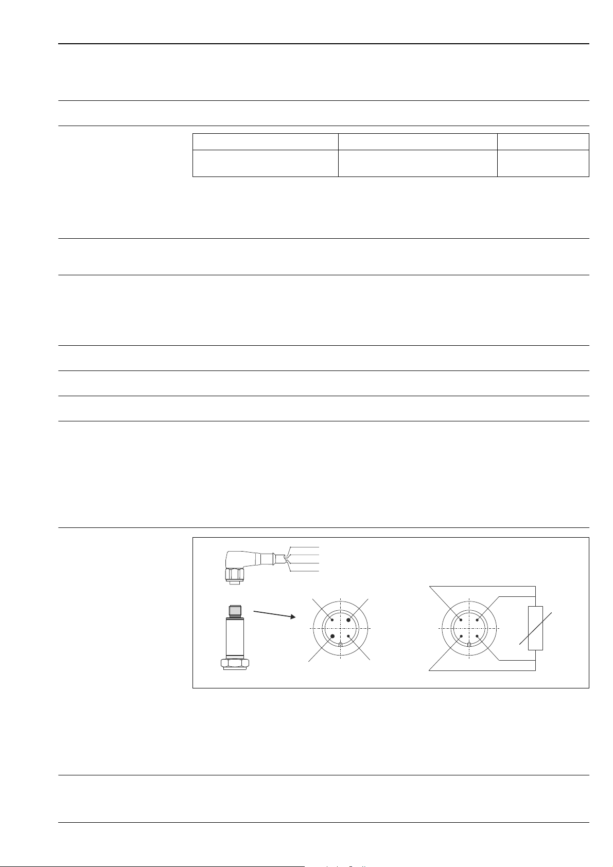
Electrical connection
Power supply
Electrical connection cables must comply with 3-A sanitary standard, must be smooth, corrosion
resistant and cleanable.
1 (BN) +
2 (WH) nc
3 (BU) 4 (BK) nc
4
M12x1
1
10...35 VDC
(4-20 mA)
A: with electronics, M12 plug, 4-pin
Pin 1: power supply 10 to 35 V DC; current output 4 to 20 mA (cable connection, wire color brown = BN)
Pin 2: connection of PC configuration cable - shortened pin (cable connection, wire color white = WH)
Pin 3: power supply 0 V DC; current output 4 to 20 mA (cable connection, wire color blue = BU)
Pin 4: connection of PC configuration cable - shortened pin (cable connection, wire color black = BK)
B: without electronics, Pt100, 4-wire connection
A
3
0 V
(4-20 mA)
2
B
J
Pt100
A0020176
Supply voltage Ub= 10 to 35 V DC
Endress+Hauser 3

TMR31, TMR35
Residual ripple Permitted residual ripple Uss 3 V at Ub 13 V, f
Performance characteristics
Response time 3 s with transmitter
Reference operating conditions
Maximum measured error Electronics
• Matching temperature (ice bath) 0 °C (32 °F) for Pt100 sensor
• Ambient temperature 25 °C ± 5 °C (77 °F ± 9 °F) for transmitter
0.1 K (0.18 °F) or 0.08%. % relates to the set span. The larger value applies.
Sensor (Pt100) for version without transmitter
• Tolerance class A as per IEC 60751, operating temperature range -50 to 200 °C (-58 to 392 °F) with
neck
• Maximum measured error in °C = 0.15 + 0.002 T
T = Numerical value of the temperature in °C without regard to the leading sign.
Total deviation of electronics + sensor
• Operating temperature range:
-50 to 150 °C (-58 to 302 °F) without neck
-50 to 200 °C (-58 to 392 °F) with neck
• 0.25 K + 0.002 T
max.
= 1 kHz
Long-term stability of electronics
Influence of ambient temperature (temperature drift)
0.1 K (0.18 °F)/year or 0.05%/year
Data under reference conditions. % relates to the set span. The larger value applies.
• Pt100 resistance thermometer:
T
= ±(15 ppm/K * (full scale value of measuring range + 200) + 50 ppm/K * set measuring range)
d
* T
T= deviation of ambient temperature from the reference operating condition.
Influence of load ± 0.02%/100
Specifications refer to the full scale value of the measuring range.
Transmitter response time 1 s
Sensor response time Measured as per IEC 60751, in water flowing at 0.4 m/s (1.3 ft/s)
t
50
< 1.0 s < 2.0 s
t
90
Influence of supply voltage ± 0.01%/V deviation from 24 V
Specifications in percent refer to the full scale value of the measuring range.
Self-heating Negligible small
Sensor current 0.6 mA
4 Endress+Hauser
TMR31, TMR35
Installation conditions
Orientation No restrictions. However, self-draining in the process must be guaranteed. If there is an opening to
detect leaks at the process connection, this opening must be at the lowest possible point.
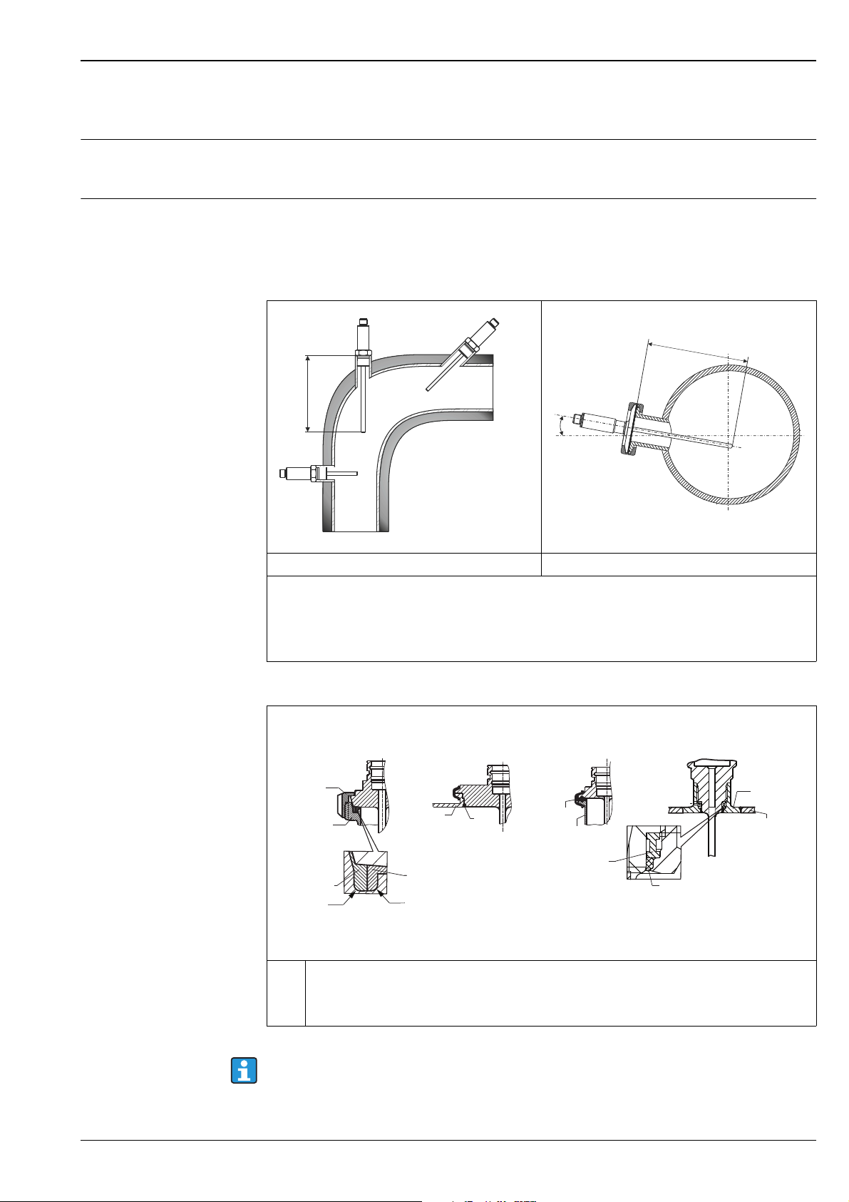
Installation instructions Mounting location
The insertion length of the compact thermometer can have a substantial influence on the accuracy. If
the insertion length is insufficient, heat dissipation via the process connection and the container wall
can cause measurement errors. To minimize errors caused by heat dissipation, a minimum insertion
length of L
= 40 mm (1.6 in) is recommended.
min
AB
L
C
A0020345
³ 3°
C
L
TMR31 - general applications TMR35 - hygienic applications
Pipe installation of the compact thermometer:
• A: On angle brackets
• B: In smaller pipes, inclined
• C: Perpendicular to the direction of flow, TMR35 with minimal 3° inclination because of self draining
• L = Insertion length
12
3
4
A0012591
Groove
slip-on nut
Companion
Companion
connection
Centering rin g
.4
0
R
Mounting instructions for installation in various hygienic processes
1
Milk pipe connection as per DIN 11851 only in connection EHEDG certified and self centering ring
2
to EHEDG position paper
3
Clamp as per ISO 2852, only in connection with seal according to EHEDG position paper
4
Liquiphant-M G1" process connection, horizontal installation
connection
Sealing
R0.4
O-rin g
Shaped
gasket
Companion
connection
Pressure rin g
O-rin g
Welding boss
Vessel wall
A0011758-EN
The matches for the process connections as well as the gaskets are not included in the scope of delivery
of this assembly. Welding adapter for process connections with associated O-ring sets are available as
accessories, 15.
Endress+Hauser 5
Procedure in case of seal failure indicated by leak detection port:
• Disassembling of the thermometer, validated cleaning procedure of thread and sealing ring groove
• Replacement of the seal or sealing ring
• CIP after re-assembly
In the case of weld-in connections, exercise the necessary degree of care when performing the welding
work on the process side:
• Suitable weld material.
• Flush welding or with welding radius > 3.2 mm.
• Absence of pits, folds, crevices.
• Ground and polished surface (R
As a general rule, the thermometers should be installed in such a way that does not adversely affect
their cleanability (3-A requirements must be adhered to). The required flush-mounting can be
achieved by the connection Varivent
Environment conditions
Ambient temperature limits -40 to +85 °C (-40 to 185 °F)
0.76 μm).
a
®
, Liquiphant (+ weld-in adapter).
TMR31, TMR35
Storage temperature -40 to +85 °C (-40 to 185 °F)
Altitude
Up to 2000 m (6600 ft) above mean sea level
Climate class As per IEC 60654-1, Class C
Degree of protection IP66/67 with coupling and connecting cable (not evaluated by UL) 15
IP69K with cordset (not evaluated by UL) 15
Shock resistance 4g / 2 to 150 Hz as per DIN EN60068-2-6
Vibration resistance Refer to ’Shock resistance’
Electromagnetic compatibility (EMC)
EMC to all relevant requirements of the IEC/EN 61326- series and NAMUR NE21. For details see
declaration of conformity.
ESD (Electrostatic discharge) IEC/EN 61000-4-2 6 kV cont., 8 kV air
Electromagnetic fields IEC/EN 61000-4-3 0.08 to 2 GHz 10 V/m
Burst (fast transient) IEC/EN 61000-4-4 2 kV
Surge IEC/EN 61000-4-5 0.5 kV sym.
Conducted RF IEC/EN 61000-4-6 0.01 to 80 MHz 10 V
All EMC measurements were performed with a turn down (TD) = 2:1. Maximum fluctuations during
EMC- tests: < 1 % of measuring span.
Interference immunity to IEC/EN 61326 - series, requirements for industrial areas
Interference emission to IEC/EN 61326 - series, electrical equipment Class B.
Condensation Permitted
Electrical safety • Protection class III
• Overvoltage category II
• Pollution degree 2 III
6 Endress+Hauser
TMR31, TMR35
Process conditions
Process temperature limits The electronics of the TMR31 and TMR35 must be protected from temperatures above 85 °C (185 °F)
by a neck of appropriate length. TMR31 and TMR35 compact thermometers without electronics
(Pt100, 4-wire) do not require a neck.
• -50 to 150 °C (-58 to 302 °F) without neck
• -50 to 200 °C (-58 to 392 °F) with neck
• -50 to 200 °C (-58 to 392 °F) without electronics
Restrictions depending on process connection and ambient temperature:
• For installation with adjustable insertion length (welding boss with sealing taper, Order No.
51004751; collar welding boss Order No. 51004752; compression fitting with sealing taper,
Order No. 51004753) provide a neck with an appropriate length.
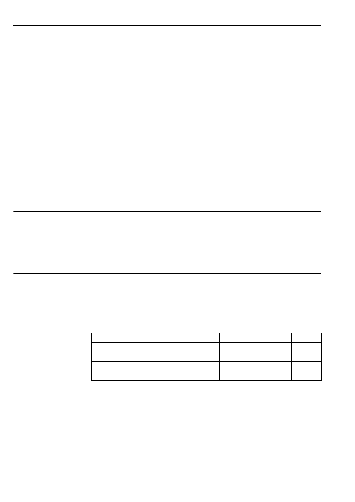
• For TMR31 with process connection:
Max. ambient temperature Max. process temperature
Without neck With neck 35 mm (1.38 in)
Up to 25 °C (77 °F) 150 °C (302 °F) 200 °C (392 °F)
Up to 40 °C (104 °F) 135 °C (275 °F) 180 °C (356 °F)
Up to 60 °C (140 °F) 120 °C (248 °F) 160 °C (320 °F)
Up to 85 °C (185 °F) 100 °C (212 °F) 133 °C (271 °F)
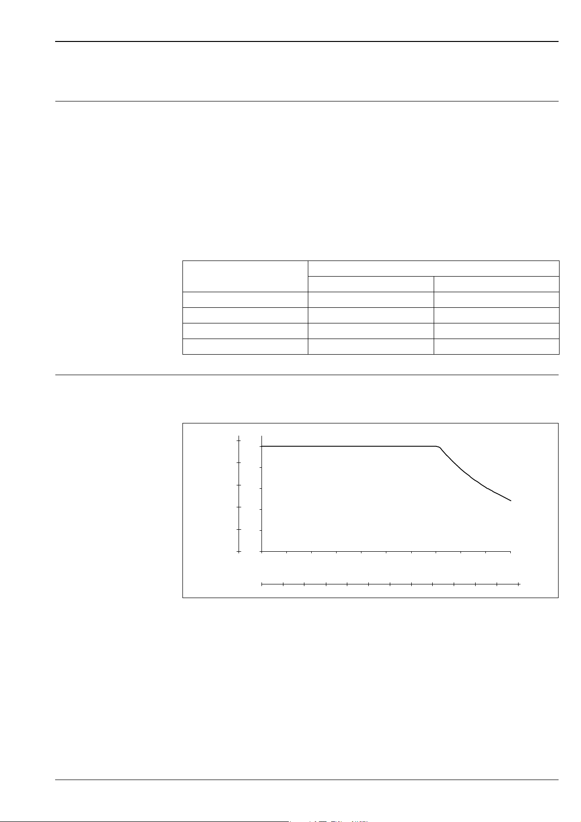
Process pressure limits Maximum permitted process pressure depending on the insertion length. It is limited further by the
process connection in question. Follow the designs of process connection in section "Mechanical
construction" and section "Accessories".
P (psi)
P (bar)
1500
100
1200
Maximum permitted process pressure
L Insertion length
p Process pressure
900
600
300
0
80
60
40
20
0
0 30 60 90 120 150 180 210 240 270 300
01234 5 78910
L (mm)
6
L (in)
11
12
A0008063
The diagram takes into consideration not only the overpressure but also the pressure load caused by
the flow, whereby a safety factor of 1.9 has been specified for operation with flow. The maximum
permitted static operating pressure is lower at greater insertion lenghts due to the increased bending
load caused by the flow. The calculation assumes the maximum permitted medium velocity for the
respective insertion length (see diagram below).
Endress+Hauser 7
 Loading...