

Endress+Hauser TMD1000, TMD1 Operating Instructions Manual
Products Solutions Services
BA00428G/08/EN/02.14
71244425
Operating Instruction
TMD1000 TMD1
Digital Transmitter Module Setting and Adjustment

TMD1000 TMD1 module setting and adjustment
2 Endress+Hauser
Table of Contents
1 Safety instructions. . . . . . . . . . . . . . . . . . . . . . . . . . . . . 3
1.1 Designated use . . . . . . . . . . . . . . . . . . . . . . . . . . . . . . . . . 3
1.2 Installation, commissioning, and operation . . . . . . . . . 3
1.3 Product requirements . . . . . . . . . . . . . . . . . . . . . . . . . . . 3
1.4 Operational safety . . . . . . . . . . . . . . . . . . . . . . . . . . . . . . 3
1.5 Notes on safety conventions and symbols . . . . . . . . . . . 4
1.6 Symbols for certain types of information . . . . . . . . . . . 4
2 Module outline . . . . . . . . . . . . . . . . . . . . . . . . . . . . . . . 5
2.1 Module types . . . . . . . . . . . . . . . . . . . . . . . . . . . . . . . . . . . 5
2.2 Mother board . . . . . . . . . . . . . . . . . . . . . . . . . . . . . . . . . . . 6
2.3 Combination in modules . . . . . . . . . . . . . . . . . . . . . . . . . 7
2.4 Precautions for addition and change of modules . . . . . 7
3 Module installation . . . . . . . . . . . . . . . . . . . . . . . . . . . 8
4 Module adjustment . . . . . . . . . . . . . . . . . . . . . . . . . . . 9
4.1 Extension board Exp-A module . . . . . . . . . . . . . . . . . . . 9
4.2 Temperature system Thermo-A module . . . . . . . . . . . 16
4.3 4 to 20 mA output DAC-1 module . . . . . . . . . . . . . . . . 19
4.4 Parallel output OUT-3 and OUT-4 module . . . . . . . . . 22
4.5 Contact output (Alarm) Exp-A module . . . . . . . . . . . . 26
4.6 4 to 20mA input ADC-2 module . . . . . . . . . . . . . . . . . . 28
4.7 Optical (FFi) communication ODC-1 module. . . . . . . . 29
4.8 Contact input (Status) Exp-A module . . . . . . . . . . . . . 33
4.9 Contact input (Status) Exp-A module. . . . . . . . . . . . . . 34
4.10 DRM9700 interface DRMM-A module. . . . . . . . . . . . . 35
4.11 Output for external device operation CNT-2 module 36
4.12 Level A/D conversion MIF4 module . . . . . . . . . . . . . . . 37
4.13 Alarm contact output CD-688 module . . . . . . . . . . . . . 38
5 Terminals and wiring table . . . . . . . . . . . . . . . . . . . 39
5.1 A - 1 H . . . . . . . . . . . . . . . . . . . . . . . . . . . . . . . . . . . . . . . 39
5.2 A - 2 H . . . . . . . . . . . . . . . . . . . . . . . . . . . . . . . . . . . . . . . 40
5.3 B - 2 H . . . . . . . . . . . . . . . . . . . . . . . . . . . . . . . . . . . . . . . 41
5.4 B - 3 H . . . . . . . . . . . . . . . . . . . . . . . . . . . . . . . . . . . . . . . 42
5.5 C H . . . . . . . . . . . . . . . . . . . . . . . . . . . . . . . . . . . . . . . . . . 43
5.6 E H . . . . . . . . . . . . . . . . . . . . . . . . . . . . . . . . . . . . . . . . . . . 44
5.7 550 H . . . . . . . . . . . . . . . . . . . . . . . . . . . . . . . . . . . . . . . . .45
5.8 A - 2 H Optical FFi . . . . . . . . . . . . . . . . . . . . . . . . . . . . . 46
6 Troubleshooting . . . . . . . . . . . . . . . . . . . . . . . . . . . . . 47
6.1 Return . . . . . . . . . . . . . . . . . . . . . . . . . . . . . . . . . . . . . . . 47
6.2 Disposal . . . . . . . . . . . . . . . . . . . . . . . . . . . . . . . . . . . . . . 47

TMD1000 TMD1 module setting and adjustment
Endress+Hauser 3
1 Safety instructions
1.1 Designated use
TMD1 is available in a variety option module. By installing modules as necessary, various customer
specification requests may be built and filled economically.
1.2 Installation, commissioning, and operation
• Mounting, electrical installation, start-up, and maintenance of the instrument may only be performed by trained personnel authorized by the operator of the facility.
• Personnel must read and understand these installation instructions before performing the procedures.
• The instrument may only be operated by personnel who are authorized and trained by the operator
of the facility. All instructions in this manual must be observed.
• The installer must make sure that the measuring system is correctly wired according to the wiring
diagrams. The measuring system must be grounded.
• Observe all law and regulations applicable and valid for your country and pertaining to the opening
and repairing of electrical devices.
1.3 Product requirements
• Exercise extreme cautions for operation in the high places or other hazardous areas such as a top of
the tank.
• Be sure to turn off the main power supply during setting modules.
• Confirm module connector connections and number of cable terminals before turning the main
power on. Failure to do so will damage to modules or connected devices.
• As C-MOSIC is used for modules, static electricity may damage modules. Do not leave modules outside after removing modules from dielectric bags.
• Do not change settings of module trimmer and jumper pins. TMD1 has been preset at factory. If
need arise, follow the module setting of this instruction.
1.4 Operational safety
Changes or modifications other than those expressly approved by Endress+Hauser are strictly prohibited. Unauthorized modifications can cause malfunction or damage, resulting in serious injury or
death.
1 Safety instructions
TMD1000 TMD1 module setting and adjustment
4 Endress+Hauser
1.5 Notes on safety conventions and symbols
To highlight safety-relevant or alternative operating procedures in this manual, the following conventions have been used, each indicated by a corresponding symbol on the left.
1.6 Symbols for certain types of information
Symbol Meaning
A0011189-EN
DANGER!
This symbol alerts you to a dangerous situation. Failure to avoid this situation will result in
serious or fatal injury.
A0011190-EN
WARNING!
This symbol alerts you to a dangerous situation. Failure to avoid this situation can result in
serious or fatal injury.
A0011191-EN
CAUTION!
This symbol alerts you to a dangerous situation. Failure to avoid this situation can result in
minor or medium injury.
A0011192-EN
NOTICE!
This symbol contains information on procedures and other facts which do not result in
personal injury.
Symbol Meaning
A0011182
Allowed
Indicates procedures, processes or actions that are allowed.
A0011183
Recommendation
Indicates procedures, processes or actions that are recommended.
A0011184
Forbidden
Indicates procedures, processes or actions that are forbidden.
A0011193
Tip
Indicates additional information.
DANGER
WARNING
CAUTION
NOTICE
1 Safety instructions

TMD1000 TMD1 module setting and adjustment
Endress+Hauser 5
2 Module outline
2.1 Module types
TMD1 is available in a variety option modules. By installing modules as necessary, various customer
specification requests may be built and filled economically.
• The size shows largeness of the modules; A (large), B (medium), C (small). The size of the module
may hinder to install modules due to slot positions (refer to "3 Mother Board").
• Number of terminals for standard use shows actual used numbers of exterior terminals for cable
connecting when installing modules. As the connections between the module connector and terminals are wired within the standard cable pattern, the number of module terminals is limited.
• The number of terminals which can be used for entire modules is 30 terminals (No.7 to No.36) at a
maximum for small terminal box and 40 terminals (No.7 to No.48) at a maximum for large terminal
box.
• Some modules are installed in predetermined slot positions regardless of their sizes. The position is
shown in the slot field of a table.
Name Functions Size
Number of
terminals for
standard use
Remakes
Main CPU - B CPU module A 6 Be sure to install this module
Exp - A
2-way 2-wire digital pulse
Contact output (alarm) 4 points
Contact input (status) 4 points
A
2
8
8
Transistor output
Thermo - A
Average temperature
Spot temperature
A
12
3
For average and sport temperatures
DAC - 1 4 - 20mA analog output C 2 2 modules are available to install.
OUT- 3/4 BCD parallel output B 18
OUT-3 (collector common)
OUT-4 (emitter common)
OUT - 2 Alarm contact output C 8
standard 4 points (max. 8 points)
Transistor output
ADC - 2
DC 4 - 20mA
Analog signal input
C2
Available only using for 2-wire
transmission board
INT - 2 Status input C 16
Available only using for 2-wire
transmission board (max. 8
points)
INT - 1 Status input C 8
Available only using for 2-wire
transmission board (max. 4
points)
DRMM- A DRM communication C 2
ODC-1N
Optical communication
(2-way half-duplex transmission)
Optical digital pulse
C0
CNT-2 External operation device output B 16 Max. 8 points
CD-688 Alarm contact output C 8
Standard 4 points (max. 8 points)
Mechanical relay output
NOTICE
2 Module outline
TMD1000 TMD1 module setting and adjustment
6 Endress+Hauser
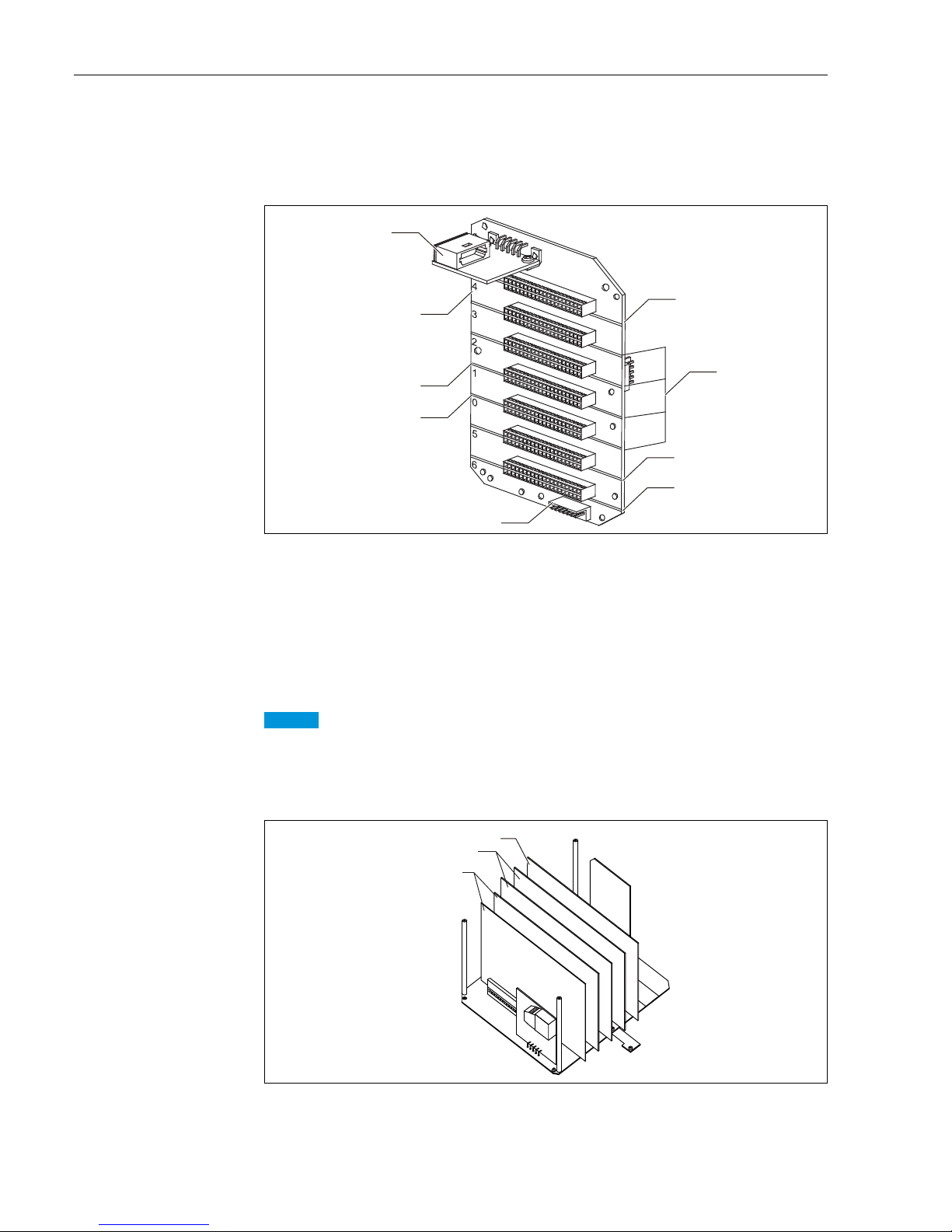
2.2 Mother board
Each module A, B, and C shows the maximum size to be installed. The size A module can be installed
in any of the slot A, B, or C.
Figure 1: Description of mother board
1. Size B
2. Size A
3. Size C
4. HHT2 fiber I/F module
5. Slot number
6. Bord for Exp-A module
7. Bord for main CPU module
8. Bord for MIF-4 module
• Be sure to install Main CPU-B module in slot 0. However, if Exp-A module is installed in slot 5, it
should be used as a pair with Main CPU-B module. Be sure to install Main CPU-B in slot 1.
• Five slots for option modules (2 CPU modules) are prepared. The option module cannot be installed
at this limitation.
Figure 2: Sample of module installation
1. Size B
2. Size A
3. Size C
1
2
1
3
4
5
6
7
8
NOTICE
1
2
3
㻠
㻌
㻟
㻌
㻌
㻞
㻌
㻌
㻝
㻌
㻌
㻜
㻌
㻌
㻡
㻌
㻌
㻢
㻌
2 Module outline

TMD1000 TMD1 module setting and adjustment
Endress+Hauser 7
2.3 Combination in modules
The five modules for options can be installed at a maximum. The maximum number of module terminals and module size in total are described above.
2.4 Precautions for addition and change of modules
Confirmation of specifications
Refer to "2.3 Combination in Modules" and follow the instructions if a module is added or changed after
delivering TMD1.
Confirmation of terminals
Confirm that module addition or change is available or not, checking terminal table.
Confirmation of cable pattern
There are some cable patterns (to connect with module connectors and terminals) as needed. Confirm
that the actual cable pattern is satisfied with the specification after changing or adding modules.
2 Module outline

TMD1000 TMD1 module setting and adjustment
8 Endress+Hauser
3 Module installation
Installation procedure
1. Turn off the main power, then open the electrical chamber rid.
2. Remove the module bracket.
3. Install the module in the slot.
4. Replace the module bracket.
5. Follow the terminal table to connect connectors to modules.
• ① to ⑨ in the terminal table is displayed on the connector.
6. Close the electrical chamber rid and turn on the main power.
7. Confirm actual status of modules.
8. Confirm that the modules are activated by using HHT2.
This completes the installation procedure.
• Confirm slot positions (specified positions and size).
• Remove main CPU-B module first to install 1 and 2 modules.
• Make sure to connect modules to connector securely to prevent misalignment of pin position or dis-
connection of connector).
NOTICE
3 Module installation
TMD1000 TMD1 module setting and adjustment
Endress+Hauser 9
4Module adjustment
Module adjustment and confirmation are performed by using HHT2. Refer to each module instruction
for details. When adjusting or checking modules, make sure to close the cover.
4.1 Extension board Exp-A module
4.1.1 Outline
Modules have the following functions.
• Line driver for 2-way communication line: equivalent to PDC-1 in TMD1, TRC-1 function (communication control module in TMD1) is integrated into main CPU-B.
• Contact Output (Alarm): equivalent to Exp-A in TMD1
• Contact Input (Status): equivalent to INT-2 in TMD1
2-way communication
Exp-A transfers the data such as level, temperature, and alarm status signal for level gauge by converting into current module pulse to a receiver. The receiver selects a slave device and transfers the level
gauge operation data by converting into pulse-width modulation (PWM) to Exp-A. The former function is called data transfer mode and latter function is called select mode. The communication only for
data transfer mode is called one-way communication.
Contact output (Alarm)
This is used when it outputs level or temperature alarm. There are 8 points output however, the only
4 points can be used for standard internal bond wires. If 5 points or more wires are needed, contact
Endress+Hauser representatives.
Contact inputs (Status)
This is used when it transfers status signals around device to a receiver via 2-way communication. If 5
points or more wires are needed, contact Endress+Hauser representatives.
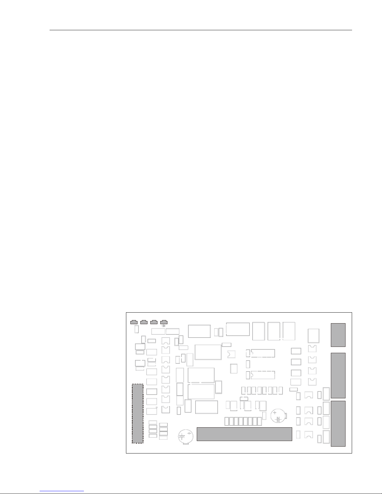
4.1.2 General view of module and names
Figure 3: Exp-A module
LED4 LED3 LED2 LED1
R1
R2
R4
V1
C1
V2
C2
R9
CN5
1A 1B
13A 13B
R5
PC1
R7
PM1
R8
PC2
C3
PM2
R10
R11
R12
R13
R14
R15
R16
R17
R18
R19
R20
R21
PC3
R26
PM5
PV4
R25
PM3
R24
R22
R6
R3
D1
C
D2
D3 R23
R27
R23
C4
20A
TR2
D6
B
E
C
R32
R33
R34
R31
R30
D5
TR1
B
E
R29 D4
PM6
RY1
C5
R35
C6
R37 R38
R39
R40
R41
R42
R43
R36
R44
C7 U5 U6 C9 U7
C8
R45
D13
CN1 1A
C11
U3
Z1 Z2 Z3
AR1
R46
R47
R48
R49
C10
R50
R51
R52
R53
PC11
PC10
PC9
PC8
PC7
PC6
PC5
PC4
CN2
CN3
5A 5B
1A 1B
1
10
R54
R58
R59
R55
R56
R60
R57
R61
10
CN4
U4
4 Module adjustment

TMD1000 TMD1 module setting and adjustment
10 Endress+Hauser
4.1.3 Module setting
Exp-A is installed in slot 1 and connected to Main CPU-B.
4.1.4 2-way communication setting
Switch to direct access mode in a receiver and adjust Exp-A so that it can access desired slave devices.
Selection of 2-way communication type
Select a type as follows in MODE:13 and ITEM: 26.
• [2]: BBB & MIC receiver
• [4]: MDP receiver
• [8]: V1 receiver
Select code setting
Set the select address (01 to FF) which a receiver has allocated in this slave device.
Set FF when selecting MIC receiver (one-on-one 2-way receiver).
Line resistance value setting
Set default setting [7] basically.
Upper and lower limit level alarm data setting
1. Select No.1 and No.2 alarm type as follows in MODE: 13 and ITEM: 28.
2. Set the No.1 alarm level value setting in MODE: 13 and ITEM: 06.
3. Set the No.2 alarm level value setting in MODE: 13 and ITEM: 07.
4. Set alarm level hysteresis range.
• Both No.1 and No.2 alarms are consistent values.
Operation confirmation
• After completion of adjustment, switch a receiver in free scan mode, then confirm that the receiver
can receive the data from the specified slave device properly.
• When communication error is arising, confirming error descriptions using a digital oscilloscope,
then change or add clock addition value in the receiver.
• A receiver can confirm the hoisting up and stop operation, and a field operation switch or HHT2 also
can be used for operation at the same time. To maintain consistency of order, the operation priority
is set in the following order; 1) field operation switch, 2) HHT2, and 3) receiver. When filed operation switch or HHT2 functions only for level measurement, a receiver can function for any other
operations such as hoisting or stopping displacer.
• Refer to the receiver instruction for available operations and their procedures.
• The operation command from a receiver is memorized into internal TMD1 thus, when the power is
turned off and on, the original state is returned. If a receiver cannot function for level measurement
due to a receiver trouble, the following step shall be done to release the function. When changing
the setting of MODE: 13 and ITEM: 01 to FF, required operation from the receiver can be set in the
level operation.
0: No.1 = High No. 2 = Low
1: No.1 = Low No. 2 = High
2: No.1 = High No. 2 = High
3: No.1 = Low No. 2 = Low
4 Module adjustment

TMD1000 TMD1 module setting and adjustment
Endress+Hauser 11
4.1.5 Operation check by LED
4.1.6 Contact output (Alarm) adjustment and confirmation
Refer to "4.5 Contact Output (Alarm) OUT-2" for details.
4.1.7 Contact input (Status) operation confirmation
Input signal logic selection
• Select [0] or [1] for logic in the sixth digit of MEMO 1 in MODE: 00 and ITEM: 12.
• When the six digit is 0 (xxxxx0), the input signal is contact OFF (open status) and there is a signal
(logic 1).
• When the six digit is 1 (xxxxx1), the input signal ON (short) and there is a signal (logic 1).
• When the six digit is 2 to 9, there is no signal (logic 0).
• Set the value according to connected device specifications.
No. Color Flashing Descriptions
LED2 Orange Flashing on sending data
LED3 Green Flashing on receiving data
4 Module adjustment
TMD1000 TMD1 module setting and adjustment
12 Endress+Hauser
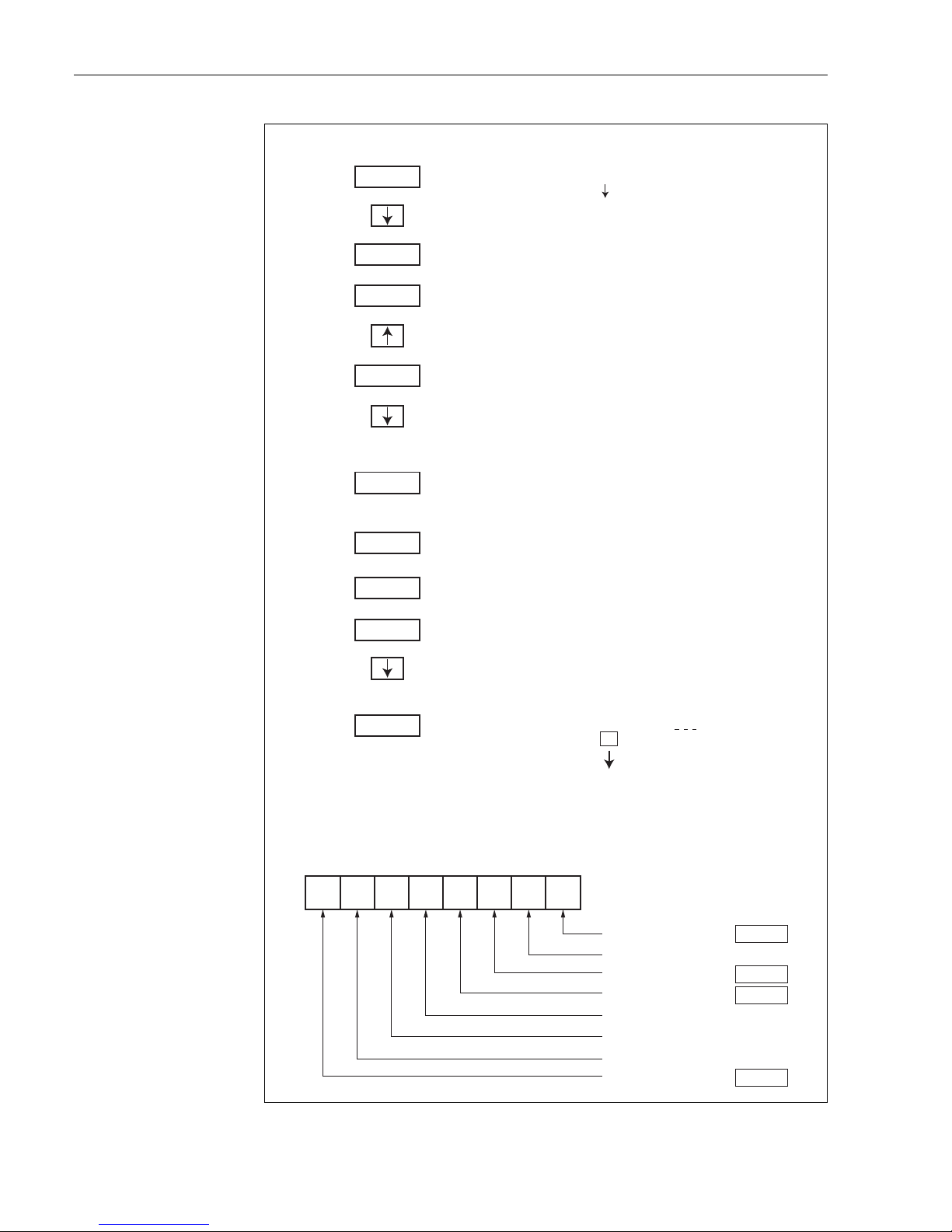
Figure 4: HHT2 operation configuration
PUSH MODE
HHT2 ROM V5.8
MODE: NO.01 TGM
OPERATION ?
ITEM NO.17
ADDRESS INPUT ?
MODO: NO.01 TGM
OPERATION ?
ITEM NO.16
DISPLAY DATA ?
ITEM NO.01
TGM 䚷NO. ?
ADDRESS
INPUT ?
ITEM NO.15
GAUGE OPE ?
SELECT DEVICE
E:TGM/TM䚷䠖NEXT
MODE: NO.00 TGM
TGM/TM DATA ?
ADDRESS䚷00034900
INPUT ?
HHT2 Operation HHT2 Status
ON
ADD: 08854
DATA 䠖 00 00 00 00
䚷䚷䚷
00䡚 FF
TGM5 Status
SELECT DEVICE
E : I/F
䚷䚷 䠖
NEXT
ENT
ENT
ENT
ENT
ENT
ENT
MODE
MODE
䞉
䞉
䞉
䞉
Input 34900.
Input 1.
01234567
11000 011
Example of status
ADD : 08854
DATA : 8C 00 00 00 00
Status 1䚷䚷0䠖OFF,䚷䚷1䠖ON
Status 2䚷䚷0䠖OFF,䚷䚷1䠖ON
Status 3䚷䚷0䠖OFF,䚷䚷1䠖ON
Status 4䚷䚷0䠖OFF,䚷䚷1䠖ON
Status 5䚷䚷0䠖OFF,䚷䚷1䠖ON
Status 6䚷䚷0䠖OFF,䚷䚷1䠖ON
Status 7䚷䚷0䠖OFF,䚷䚷1䠖ON
Status 8䚷䚷0䠖OFF,䚷䚷1䠖ON
䚷䚷
4 Module adjustment

TMD1000 TMD1 module setting and adjustment
Endress+Hauser 13
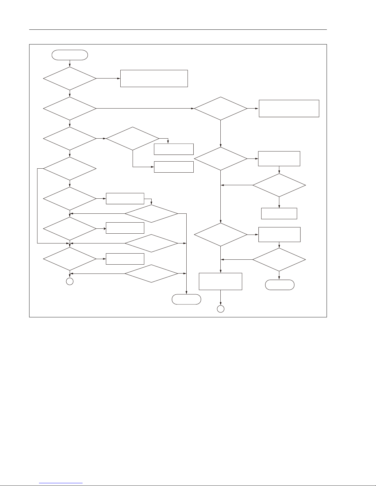
4.1.8 Troubleshooting
2-way communication
If there is a communication error, diagnosis for failure should be required, referring to the following
check point and attached flow chart.
The procedures include displaying data and error, and TMD operation confirmation using a receiver.
䕔㻌
Communication error in all tanks.
䖃㻌
Main optical fiber error
䖃㻌
Receiver error (refer to receiver manual)
䕔䚷
Specific loop error
䖃
Specific loop error in optical fiber
䚷
䖃
Specific TMD1 loop has a negative effect on the entire loop.
(e.g. Selection failure: double selection)
䕔䚷
Specific tank error
䖃
Not work at all
䖃㻌
Communication is available, but remote operation is not available.
(Operation input at site is not level measurement.)
䖃㻌
TMD1 error
䖃㻌
Specific optical fiber error
Check point
4 Module adjustment
TMD1000 TMD1 module setting and adjustment
14 Endress+Hauser
1
2
No
No
No
Yes
Yes
Yes
Yes
No
No
No
No
No
Yes
Yes
Yes
Yes
No
No
No
Yes
Yes
No
Yes
Yes
No
Yes
Communication
error arose.
Selecting tank: O.K.
Remote operation: O.K.
Improper data transmission is arising.
Is the selected
signal inputted?
Is the selected
code correct?
TMD operates
normally.
Tanks not work at all.
All tanks show
abnormal status.
Are cable polarities
correct?
Is transmission
cable loose?
Is main power
of TMD normal?
Reset
selecting codes.
Replace the cable
polarities.
Repair cable
connections.
Check and repair
TMD main power.
Completed
Improper remote
operation
Is data clock
pulses inputted?
Is transmission
error arising?
TMD opration input
is not set to “Operation” .
Return to Operation setting.
Is data clock
pulses inputted?
Replace
module Exp-A.
Reset the resistance
value of the date
transmission line.
No transmission
error, but operation
is not stable.
Abnormal status in transmitter
Trouble in transmitter
Refer to “Troubleshooting” .
Refer to “TMD
Troubleshooting” .
TMD
functions properly.
TMD
functions properly.
TMD
functions properly.
Reset the resistance
value of the date
transmission line.
Completed
All tanks
Selecting tank is O.K.
TMD functions
properly.
4 Module adjustment
TMD1000 TMD1 module setting and adjustment
Endress+Hauser 15
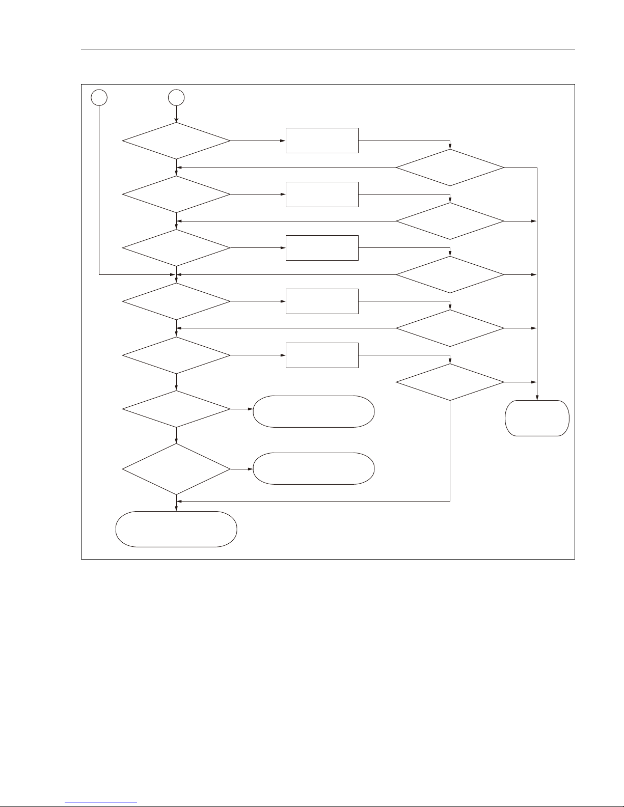
4.1.9 Precaution for use of modules
When using contact input (status) INT-1, 2 and Exp-A at the same time, INT-1 and 2 operate preferentially.
The contact input (alarm) inside Exp-A stops.
Module is
connected properly.
Increase communication
clock width and try to
be stable for communication.
(Cable malfunction)
No cable breakage
No module damage
Cables capacitance
is 0.3μF or less.
Cable resistance is
1mRUPRUH
Loop can be divided
into several parts.
Install connector
to recover TMD.
Replace cable.
Repair or replace
cable.
Replace module.
Replace
Exp-A module.
Replace with low capacitance
cable to be satisfied with
cable spec.
Divide loop and
reduce capacitance.
Cable can be replaced.
TMD functions properly.
Completed
12
TMD functions properly.
TMD functions properly.
TMD functions properly.
TMD functions properly.
No
No
No No
No
No
No
No
No
No
Yes
Yes
Yes
Yes
Yes
Yes
Yes
Yes
Yes
Yes
Yes
No
4 Module adjustment
 Loading...