

Page 1
BA01581T/09/EN/03.18
71413053
2018-08-20
Valid as of version
01.00 (device version)
Products Solutions Services
Operating Instructions
iTHERM TrustSens TM371,
TM372
Compact thermometer with self-calibration
Page 2

Page 3

iTHERM TrustSens TM371, TM372 Table of contents
Table of contents
1 About this document ................ 4
1.1 Document function ..................... 4
1.2 Symbols .............................. 4
1.3 Documentation ........................ 5
2 Basic safety instructions ............ 6
2.1 Requirements for personnel ............... 6
2.2 Intended use .......................... 6
2.3 Operation safety ....................... 6
2.4 Product safety ......................... 6
3 Incoming acceptance and product
identification ....................... 7
3.1 Incoming acceptance .................... 7
3.2 Product identification .................... 7
3.3 Transport and storage ................... 9
4 Mounting ......................... 10
4.1 Mounting conditions ................... 10
4.2 Mounting the measuring device ........... 10
4.3 Post-mounting check ................... 13
9 Diagnostics and troubleshooting ... 35
9.1 Troubleshooting ...................... 35
9.2 Diagnostic information via LEDs ........... 35
9.3 Diagnostic information ................. 36
9.4 Overview of diagnostics events ............ 37
9.5 Diagnostic list ........................ 39
9.6 Event logbook ........................ 39
9.7 Firmware history ...................... 39
10 Maintenance ...................... 40
10.1 Cleaning ............................ 40
11 Repair ............................ 41
11.1 Spare parts .......................... 41
11.2 Return .............................. 41
11.3 Disposal ............................ 41
12 Accessories ....................... 42
12.1 Device-specific accessories ............... 42
12.2 Communication-specific accessories ........ 45
12.3 Service-specific accessories ............... 46
12.4 System components .................... 47
5 Electrical connection .............. 14
5.1 Connecting requirements ................ 14
5.2 Connecting the device .................. 14
5.3 Ensuring the degree of protection .......... 14
5.4 Post-connection check .................. 15
6 Operability ........................ 15
6.1 Overview of operation options ............ 15
6.2 Structure and function of the operating
menu .............................. 16
6.3 Access to the operating menu via an
operating tool ........................ 17
7 System integration ................ 21
7.1 Overview of device description files ......... 21
7.2 Measured variables via HART protocol ...... 21
7.3
Supported HART® commands ............. 22
8 Commissioning .................... 24
8.1 Function check ....................... 24
8.2 Switching on the measuring device ......... 24
8.3 Configuring the measuring device .......... 24
8.4 Creating a calibration report .............. 26
8.5 Protecting settings from unauthorized
access .............................. 28
8.6 Advanced settings ..................... 29
13 Technical Data .................... 47
13.1 Input ............................... 47
13.2 Output ............................. 47
13.3 Wiring ............................. 48
13.4 Performance characteristics .............. 49
13.5 Environment ......................... 53
13.6 Mechanical construction ................ 54
13.7 Certificates and approvals ............... 72
14 Operating menu and parameter
description ........................ 74
14.1 Setup menu .......................... 78
14.2 Calibration menu ...................... 79
14.3 Diagnostics menu ..................... 83
14.4 Expert menu ......................... 92
Endress+Hauser 3
Page 4
About this document iTHERM TrustSens TM371, TM372
DANGER
WARNING
CAUTION
NOTICE
1 About this document
1.1 Document function
These Operating Instructions contain all the information that is required in various phases
of the life cycle of the device: from product identification, incoming acceptance and
storage, to mounting, connection, operation and commissioning through to
troubleshooting, maintenance and disposal.
1.2 Symbols
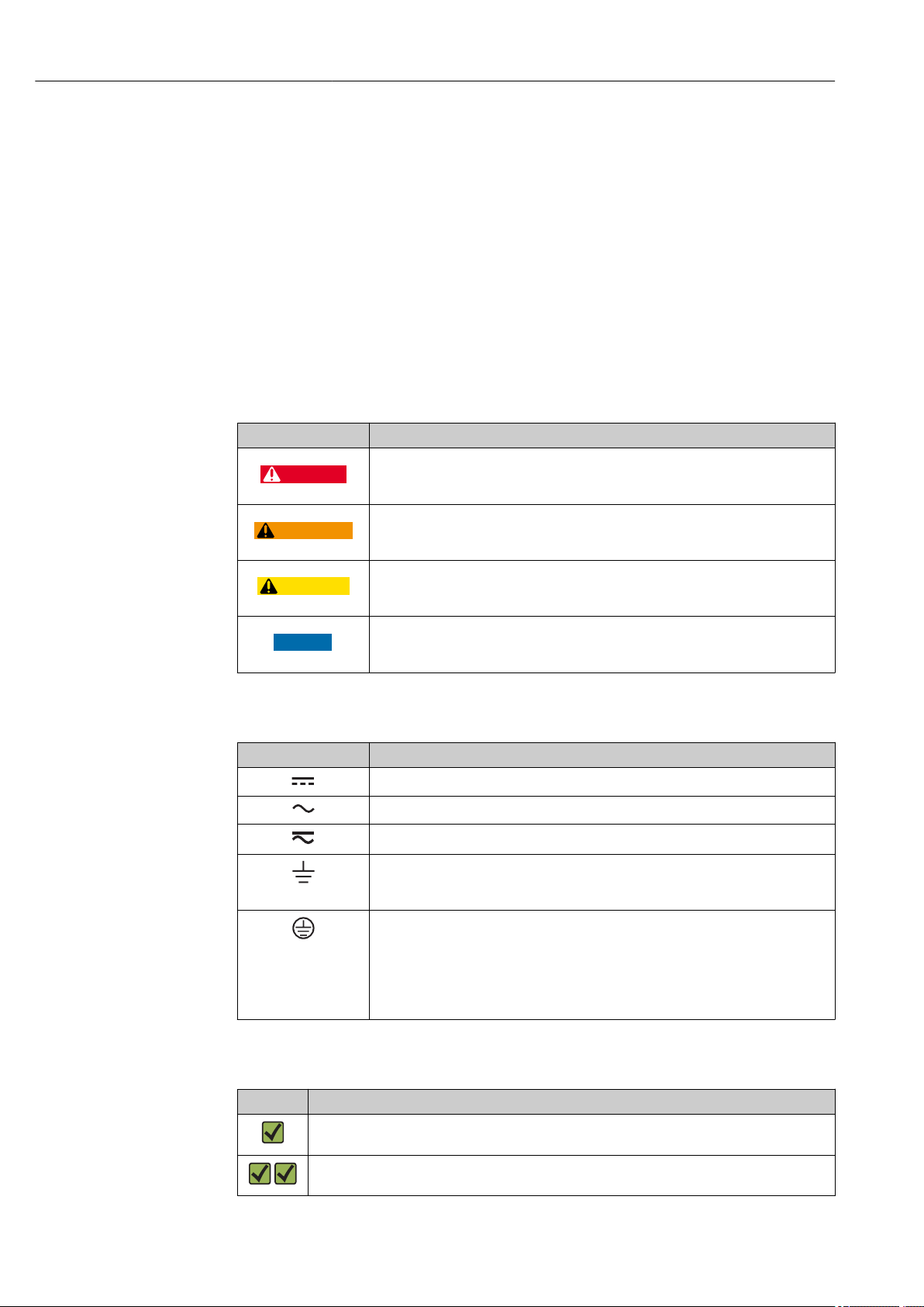
1.2.1 Safety symbols
Symbol Meaning
DANGER!
This symbol alerts you to a dangerous situation. Failure to avoid this situation will
result in serious or fatal injury.
WARNING!
This symbol alerts you to a dangerous situation. Failure to avoid this situation can
result in serious or fatal injury.
CAUTION!
This symbol alerts you to a dangerous situation. Failure to avoid this situation can
result in minor or medium injury.
NOTE!
This symbol contains information on procedures and other facts which do not result in
personal injury.
1.2.2 Electrical symbols
Symbol Meaning
Direct current
Alternating current
Direct current and alternating current
Ground connection
A grounded terminal which, as far as the operator is concerned, is grounded via a
grounding system.
Protective Earth (PE)
A terminal which must be connected to ground prior to establishing any other
connections.
The ground terminals are situated inside and outside the device:
• Inner ground terminal: Connects the protectiv earth to the mains supply.
• Outer ground terminal: Connects the device to the plant grounding system.
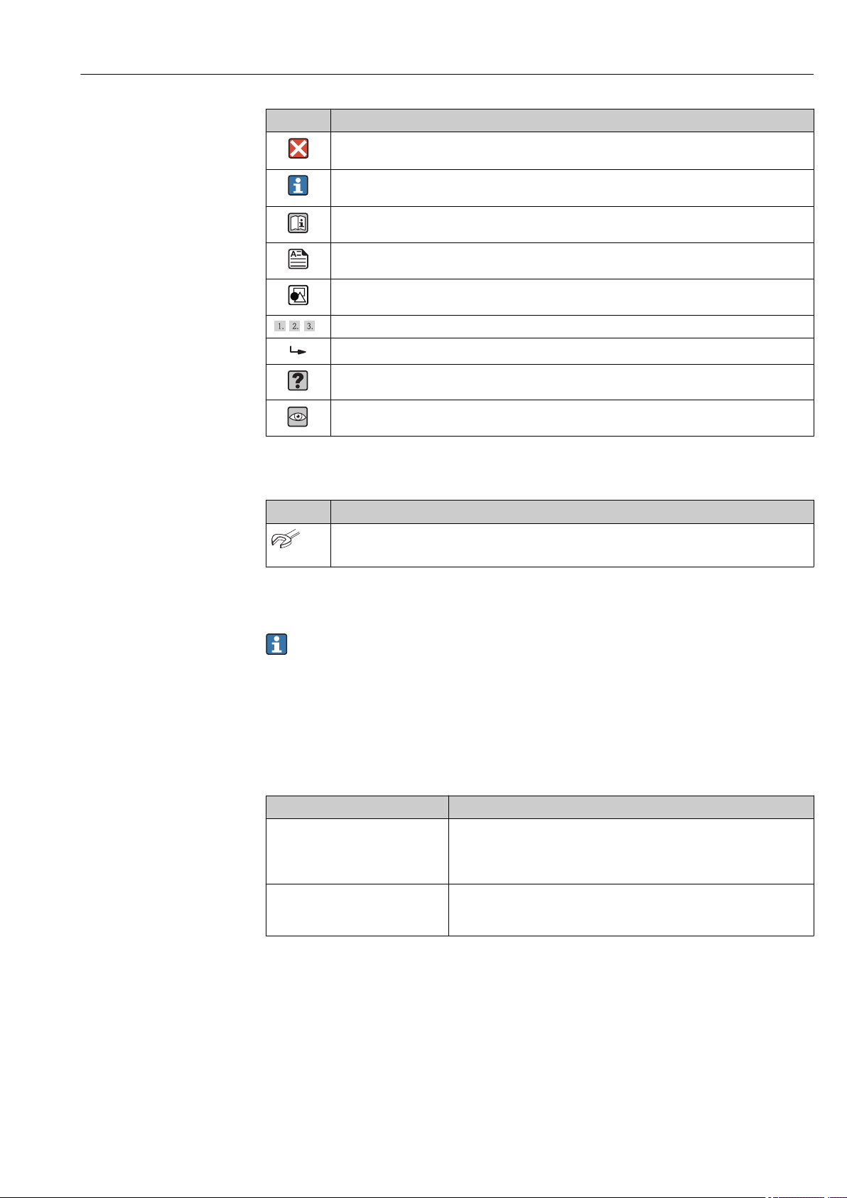
1.2.3 Symbols for certain types of information
Symbol Meaning
Permitted
Procedures, processes or actions that are permitted.
Preferred
Procedures, processes or actions that are preferred.
4 Endress+Hauser
Page 5
iTHERM TrustSens TM371, TM372 About this document
,…,
Symbol Meaning
Forbidden
Procedures, processes or actions that are forbidden.
Tip
Indicates additional information.
Reference to documentation
Reference to page
Reference to graphic
Series of steps
Result of a step
Help in the event of a problem
Visual inspection
1.2.4 Tool symbols
Symbol Meaning
Open-ended wrench
A0011222
1.3 Documentation
For an overview of the scope of the associated Technical Documentation, refer to the
following:
• W@M Device Viewer (www.endress.com/deviceviewer): Enter the serial number
from nameplate
• Endress+Hauser Operations App: Enter the serial number from the nameplate or
scan the 2D matrix code (QR code) on the nameplate
1.3.1 Standard documentation
Document type Purpose and content of the document
Technical Information Planning aid for your device
The document contains all the technical data on the device and provides
an overview of the accessories and other products that can be ordered for
the device.
Brief Operating Instructions Guide that takes you quickly to the 1st measured value
The Brief Operating Instructions contain all the essential information
from incoming acceptance to initial commissioning.
1.3.2 Supplementary device-dependent documentation
Additional documents are supplied depending on the device version ordered: Always
comply strictly with the instructions in the supplementary documentation. The
supplementary documentation is an integral part of the device documentation.
Endress+Hauser 5
Page 6

Basic safety instructions iTHERM TrustSens TM371, TM372
2 Basic safety instructions
2.1 Requirements for personnel
The personnel for installation, commissioning, diagnostics and maintenance must fulfill
the following requirements:
Trained, qualified specialists must have a relevant qualification for this specific function
‣
and task.
Are authorized by the plant owner/operator.
‣
Are familiar with federal/national regulations.
‣
Before starting work, read and understand the instructions in the manual and
‣
supplementary documentation as well as the certificates (depending on the
application).
Follow instructions and comply with basic conditions.
‣
The operating personnel must fulfill the following requirements:
Are instructed and authorized according to the requirements of the task by the facility's
‣
owner-operator.
Follow the instructions in this manual.
‣
2.2 Intended use
• The device is a compact thermometer for the acquisition and conversion of temperature
input signals for industrial temperature measurement.
• The manufacturer is not liable for damage caused by improper or non-intended use.
2.3 Operation safety
NOTICE
Operation safety
Operate the device in proper technical condition and fail-safe condition only.
‣
The operator is responsible for interference-free operation of the device.
‣
Conversions to the device
Unauthorized modifications to the device are not permitted and can lead to unforeseeable
dangers.
If, despite this, modifications are required, consult with Endress+Hauser.
‣
Repair
Due to its design, the device cannot be repaired.
However, it is possible to send the device in for examination.
‣
To ensure continued operational safety and reliability, use original spare parts and
‣
accessories from Endress+Hauser only.
2.4 Product safety
This measuring device is designed in accordance with good engineering practice to meet
state-of-the-art safety requirements, has been tested, and left the factory in a condition in
which it is safe to operate.
It meets general safety standards and legal requirements. It also complies with the EC
directives listed in the device-specific EC Declaration of Conformity. Endress+Hauser
confirms this by affixing the CE mark to the device.
6 Endress+Hauser
Page 7
iTHERM TrustSens TM371, TM372 Incoming acceptance and product identification
DELIVERYNOTE
TMT162
TrustSens
TM371, 372
3 Incoming acceptance and product
identification
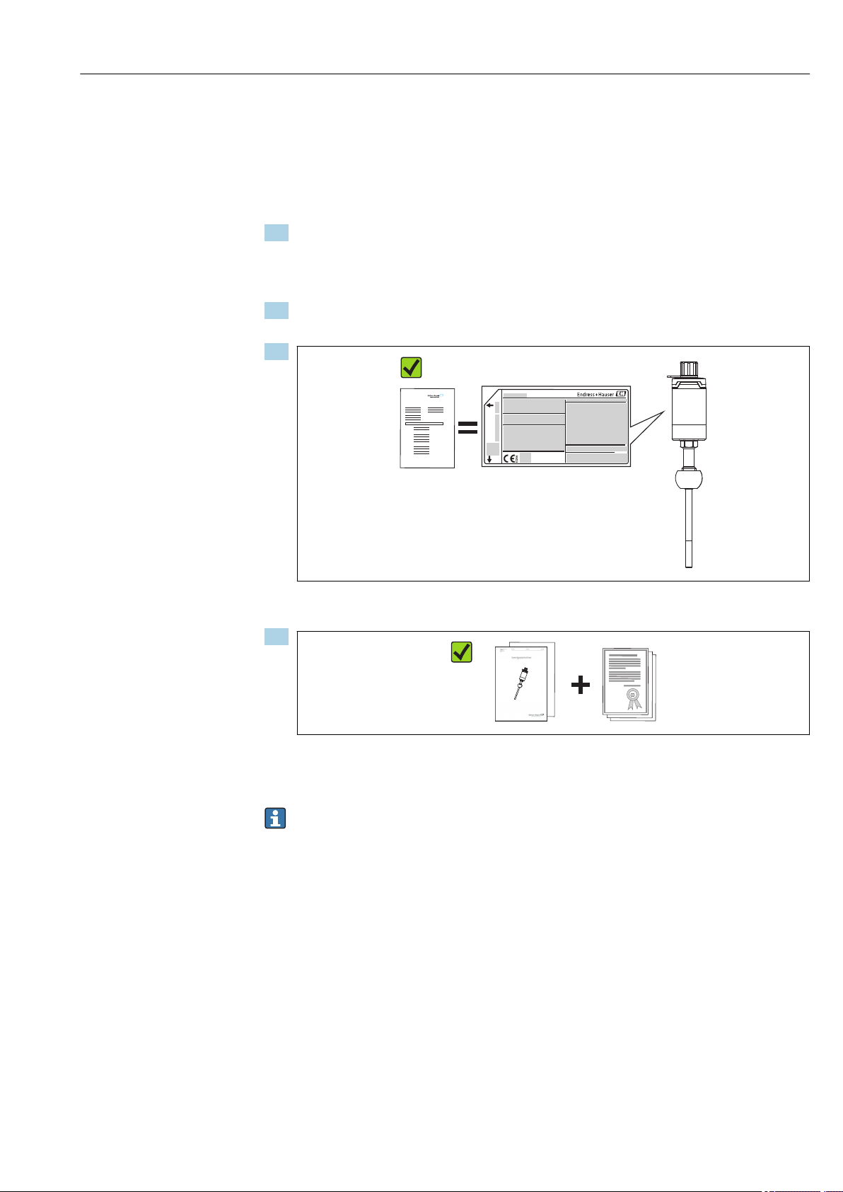
3.1 Incoming acceptance
1. Unpack the device carefully. Is the packaging or content damaged?
The damaged content must not be installed; in those conditions the
manufacturer cannot guarantee the original safety requirements or the material
resistance and cannot be considered as responsible for any consequent damages.
2. Is the delivery complete? Compare the scope of delivery against the information on
your order form.
3.
Do the nameplate data match the ordering information on the delivery note?
4.
Are the technical documentation and additional documents (e.g. certificates)
present?
If one of the conditions does not comply, contact your Endress+Hauser distributor.
3.2 Product identification
The following options are available for identification of the device:
• Nameplate specifications
• Enter the serial number from the nameplate in the W@M Device Viewer
(www.endress.com/deviceviewer): All data relating to the device and an overview of
the Technical Documentation supplied with the device are displayed.
A0028503
A0028522
Endress+Hauser 7
Page 8
Incoming acceptance and product identification iTHERM TrustSens TM371, TM372
Input:
1
2
3
4
5
6
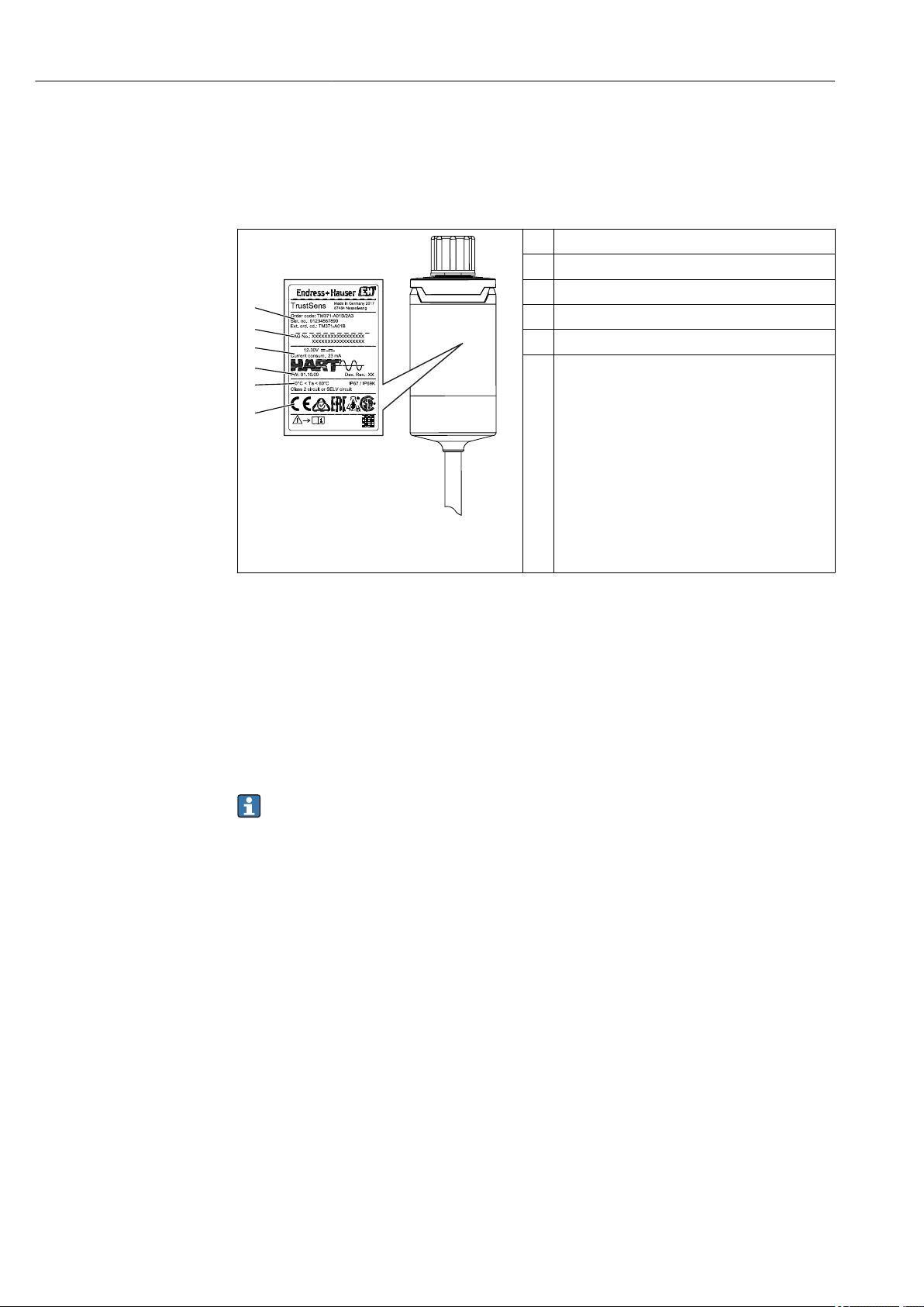
3.2.1 Nameplate
Is this the correct device?
Compare and check the data on the nameplate of the device against the requirements of the
measuring point:
1 Order code, serial number
2 Device TAG name
3 Supply voltage and current consumption
4 Device revision and firmware version
5 Ambient temperature
6 Approvals with symbols
A0033853
1 Nameplate of the compact thermometer
(example)
3.2.2 Scope of delivery
The scope of delivery comprises:
• Compact thermometer
• Hard copy of multi-language Brief Operating Instructions
• Ordered accessories
3.2.3 Certificates and approvals
An overview of further approvals and certifications is provided in the ’Technical data’
section. → 72
CE/EAC mark, declaration of conformity
The device meets the legal requirements of the EU/EEU guidelines. The manufacturer
confirms that the device is compliant with the relevant guidelines by applying the CE/EAC
mark.
Hygiene standard
• EHEDG certification, type EL - CLASS I. Permitted process connections in accordance
with EHEDG, see section 'Process connections' → 64
• 3-A authorization no. 1144, 3-A sanitary standard 74-06. Permitted process
connections in accordance with 3-A, see section 'Process connections' → 64
• ASME BPE, certificate of conformity can be ordered for indicated options
• FDA-compliant
• All product contact surfaces are produced without animal fats (TSE Certificate of
Suitability)
8 Endress+Hauser
Page 9
iTHERM TrustSens TM371, TM372 Incoming acceptance and product identification
Parts in contact with the medium
Parts of the thermometer in contact with the medium comply with the following European
regulations:
• (EC) No. 1935/2004, Article 3, paragraph 1, Articles 5 and 17 on materials and articles
intended to come into contact with food.
• (EC) No. 2023/2006 on good manufacturing practice for materials and articles intended
to come into contact with food.
• (EU) No. 10/2011 on plastic materials and articles intended to come into contact with
food.
3.3 Transport and storage
Pack the device in such a way as to protect it reliably against impact for storage (and
transportation). The original packaging provides optimum protection.
Storage temperature –40 to +85 °C (–40 to +185 °F)
Endress+Hauser 9
Page 10
Mounting iTHERM TrustSens TM371, TM372
SW/AF 32
SW/AF 17
1
2
3
4
4 Mounting
4.1 Mounting conditions
Information about the conditions, which have to be existent at the mounting location
for a designated use, such as ambient temperature, degree of protection, climate class,
etc., as well as device dimensions - see section 'Technical Data', → 47
The immersion length of the thermometer can influence the accuracy. If the immersion
length is too small then errors in the measurement are caused by heat conduction via the
process connection. If installing into a pipe then the immersion length should ideally be
half of the pipe diameter. → 10
• Installation possibilities: Pipes, tanks or other plant components
• Orientation: no restrictions. However, self-draining in the process must be guaranteed. If
there is an opening to detect leaks at the process connection, this opening must be at the
lowest possible point.
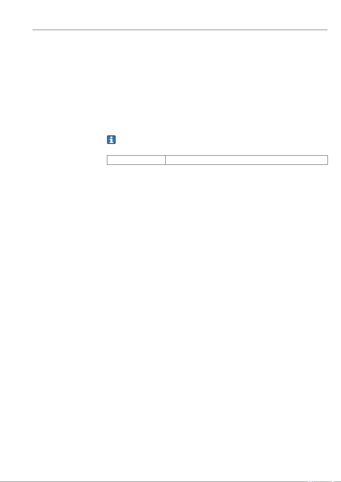
4.2 Mounting the measuring device
Required tools for mounting in an existing protection tube: Open-end wrench or mounting
socket wrench SW/AF 32
A0028639
2 Mounting process of the compact thermometer
1 Mounting of iTHERM QuickNeck connection to the existing protection tube with iTHERM QuickNeck bottom
part - no tools required
2 Hexagonal head SW/AF 32 for the mounting in an existing protection tube for M24-, G3/8"-thread
3 Adjustable compression fitting TK40 - mounting of the hexagonal screw with open-end wrench SW/AF 17
only
4 Protection tube
10 Endress+Hauser
Page 11
iTHERM TrustSens TM371, TM372 Mounting
U
≥ 3°
≥ 3°
1
2
3
4
1
2
3
4
5
M
M
M
A0031007
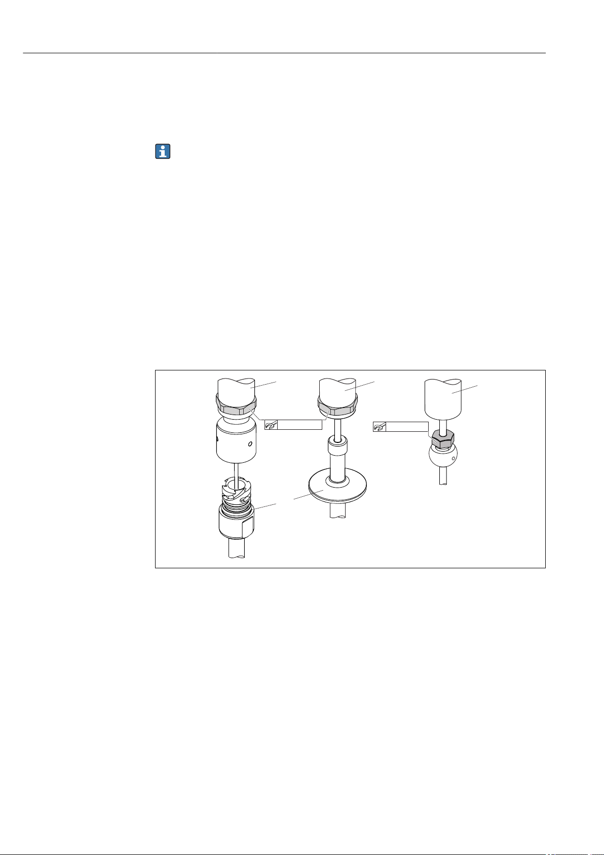
3 Mounting possibilities in the process
1, 2 Perpendicular to flow direction, installed at a min. angle of 3° to ensure self-draining
3 On elbows
4 Inclined installation in pipes with a small nominal diameter
U Immersion length
In the case of pipes with a small nominal diameter, it is advisable for the tip of the
thermometer to project well into the process so that it extends past the pipe axis.
Installation at an angle (4) could be another solution. When determining the immersion
length or installation depth all the parameters of the thermometer and of the medium to
be measured must be taken into account (e.g. flow velocity, process pressure).
Maximum torque
A0035951
Protection tube version TT411, 6 mm (0.24 in) (1)
TT411, 6 mm (0.24 in) and
Necktube TE411 (2)
Torque M 3 to 5 Nm (2.2 to 3.7 lbf ft) 10 Nm (7.4 lbf ft) 3 to 5 Nm (2.2 to 3.7 lbf ft)
TT411,
9 mm (0.35 in) (3)
TT411, 12.7 mm (¹⁄₂ in) (4)
TT411, 12.7 mm (¹⁄₂ in) and
Necktube TE411 (5)
When connecting the device with the protection tube: only turn the hexagonal
spanner flat on the bottom of the housing.
Endress+Hauser 11
Page 12
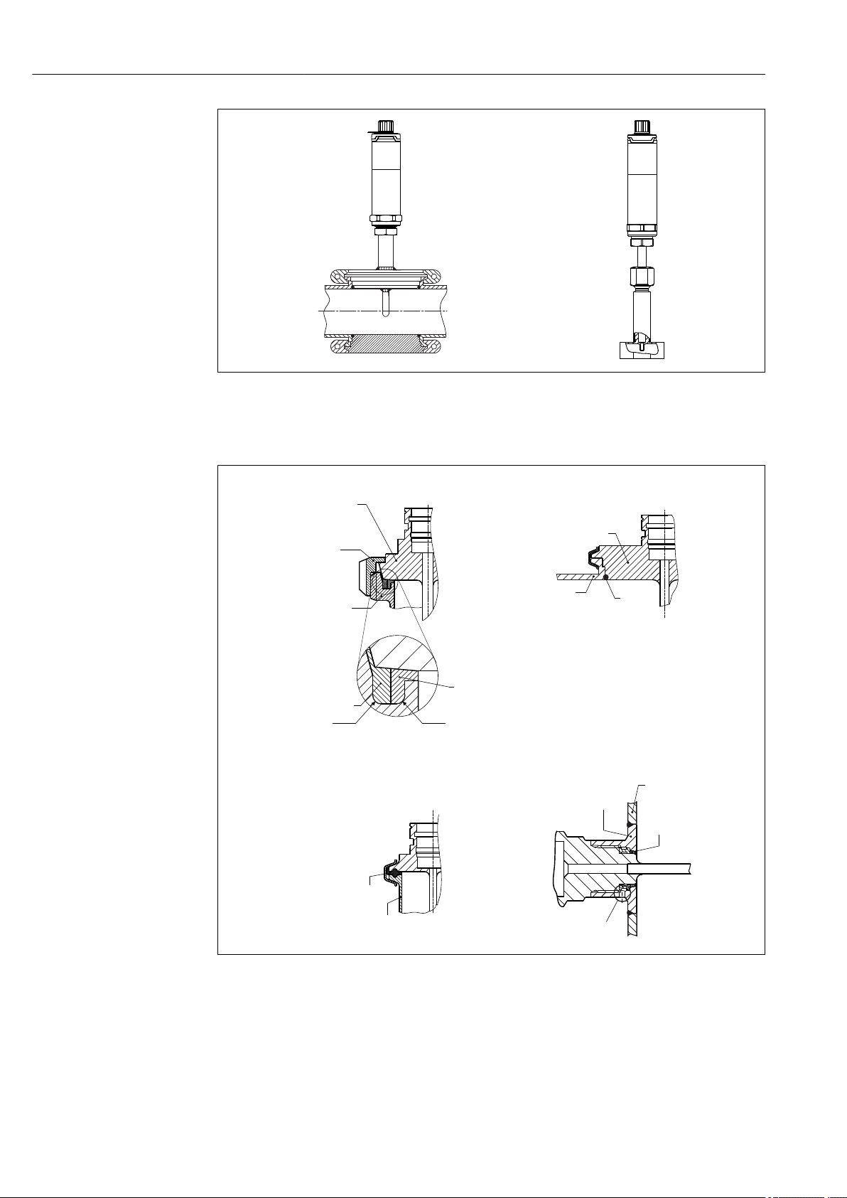
Mounting iTHERM TrustSens TM371, TM372
1
2
1 2
3 4
R0.4 R0.4
Sensor with
milk pipe
connection
Sensor Variventwith
connection
Shaped
gasket
Companion
connection
O-ring
Groove
slip-on nut
Centering ring
Sealing
Companion
connection
Companion
connection
Gasket
(O-ring)
Welding boss
Leak detection hole
Vessel wall
A0031022
4 Process connections for thermometer installation in pipes with small nominal diameters
1 Varivent® process connection type N for DN40
2 Corner piece or T-piece (illustrated) for weld-in as per DIN 11865 / ASME BPE 2012
12 Endress+Hauser
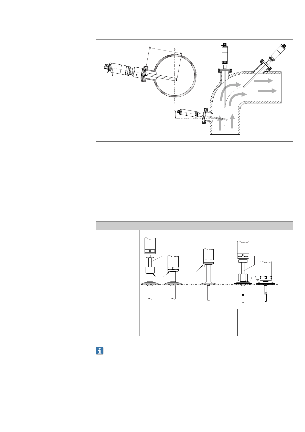
5 Detailed installation instructions for hygiene-compliant installation
1 Sanitary connection according to DIN 11851, only in connection with EHEDG-certified and self-centering
sealing ring
2 Varivent® process connection for VARINLINE® housing
3 Clamp according to ISO 2852
4 Liquiphant-M G1" process connection, horizontal installation
A0028648-EN
Page 13
iTHERM TrustSens TM371, TM372 Mounting
The counterpieces for the process connections and the seals or sealing rings are not
included in the scope of supply for the thermometer. Liquiphant M weld-in adapters with
associated seal kits are available as accessories. → 42
Procedure in case of seal failure indicated by leak detection port:
1. Disassembling of the thermometer, validated cleaning procedure of thread and
sealing ring groove
2. Replacement of the seal or sealing ring
3. CIP after re-assembly
In the case of weld-in connections, exercise the necessary degree of care when performing
the welding work on the process side:
• Suitable welding material
• Flush-welded or with welding radius > 3.2 mm (0.13 in)
• No recesses, folds or gaps
• Honed and polished surface, Ra ≤ 0.76 µm (0.03 µin)
As a general rule, the thermometers should be installed in such a way that does not
impact their ability to be cleaned (the requirements of the 3-A Standard must be
observed). The Varivent® and Liquiphant-M weld-in adapter and Ingold (+ weld-in
adapter) connections enable flush-mounted installation.
4.3 Post-mounting check
Is the device undamaged (visual inspection)?
Is the device fixed appropriately?
Does the device comply to the measurement point specifications, such as ambient temperature, etc.?
→ 47
Endress+Hauser 13
Page 14
Electrical connection iTHERM TrustSens TM371, TM372
M12x1
1
12...30 VDC
(4...20 mA)
3
0 V
(4...20 mA)
4
2
A
B
1 (BN) +
2 (WH) nc
3 (BU) -
4 (BK) nc
1.
2.
5 Electrical connection
5.1 Connecting requirements
According to the 3-A Standard electrical connecting cables must be smooth,
corrosion-resistant and easy to clean.
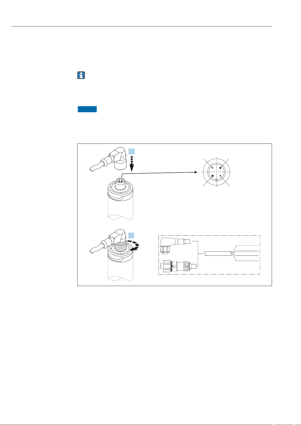
5.2 Connecting the device
NOTICE
To prevent damage to the device
To prevent any kind of damage from the device electronics, leave the pins 2 and 4
‣
unconnected. They are reserved for the connection of the configuration cable.
Do not tighten the M12 plug too much, in order to prevent damage to the device.
‣
A0028623
6 Cable plug M12x1 and PIN assignment of the connection socket at the device
If voltage supply is connected correctly and the measuring device is operational, the LED is
illuminated green.
5.3 Ensuring the degree of protection
The specified degree of proctection is ensured when the M12x1 cable plug is tightened. In
order to reach IP69K degree of protection, appropriate cord sets with straight or angle
plugs are available as accessories.
14 Endress+Hauser
Page 15
iTHERM TrustSens TM371, TM372 Operability
2 3
1
4 5
5.4 Post-connection check
Is the device or cable undamaged (visual check)?
Do the cables have adequate strain relief?
Does the supply voltage match the specifications on the nameplate?
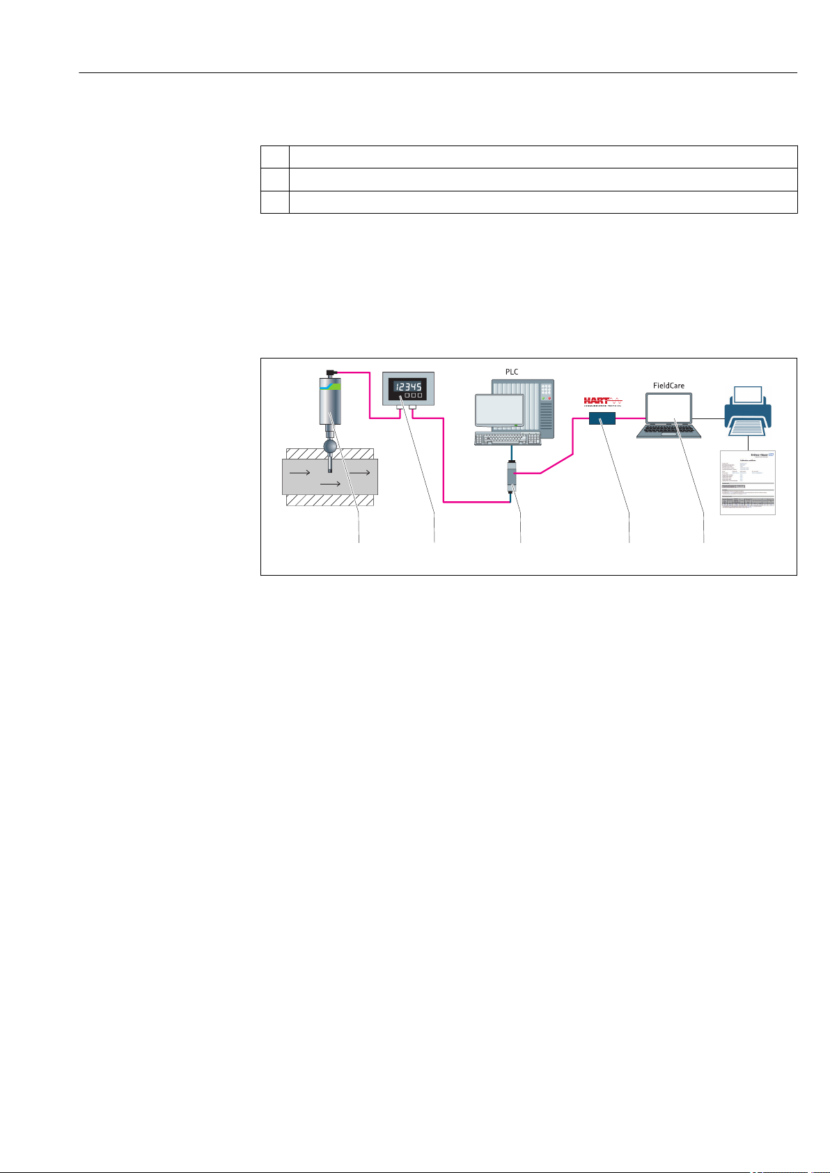
6 Operability
6.1 Overview of operation options
A0031089
7 Operating options of the device
1
Installed iTHERM compact thermometer with HART® communication protocol
2 RIA15 loop powered process display - It is integrated in the current loop and displays the measuring signal or
HART® process variables in digital form. The process display unit does not require an external power supply.
It is powered directly from the current loop.
3 Active barrier RN221N - The RN221N (24 V DC, 30 mA) active barrier has a galvanically isolated output for
supplying voltage to loop-powered transmitters. The universal power supply works with an input supply
voltage of 20 to 250 V DC/AC, 50/60 Hz, which means that it can be used in all international power grids.
4 Commubox FXA195 for intrinsically safe HART® communication with FieldCare via the USB interface.
5 FieldCare is a FDT-based plant asset management tool from Endress+Hauser, more details see section
'accessories'. The acquired self-calibration data is stored in the device (1) and can be read using FieldCare.
This also enables an auditable calibration certificate to be created and printed.
Endress+Hauser 15
Page 16
Operability iTHERM TrustSens TM371, TM372
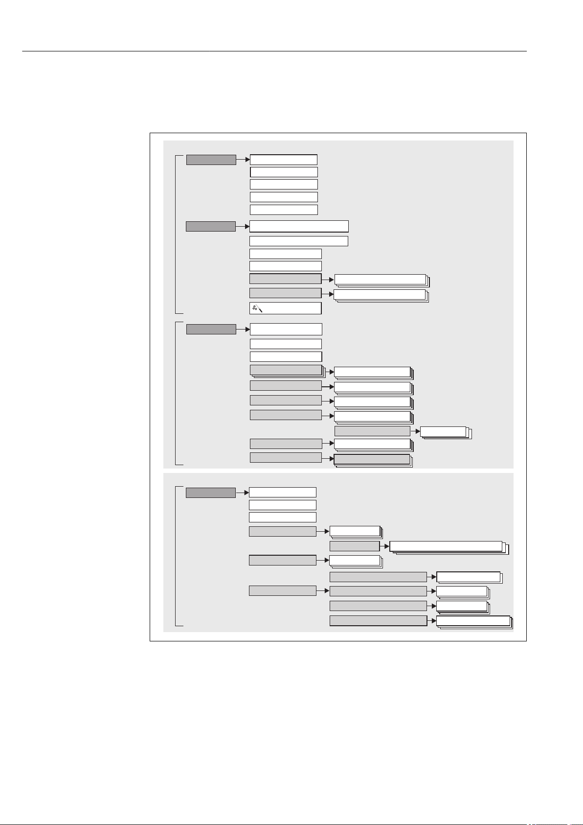
Expert
System
Communication
Operating menu for experts
Setup
Device tag
Diagnostics
Operating menu for operators and maintenances
Maintenance
Expert
Output
Unit
4 mA value
20 mA value
Actual diagnostics
Operating time
Diagnostic list
Actual diagnostics count
Enter access code
Unit
4 mA value
HART configuration
HART info
HART output
Device type
Assigncurrentoutput(PV)
Event logbook
Device information
Simulation
Previous diagnostics 1
Device tag
Min/max values
Sensor value
Measured values
Sensor min v.
Device tag
Definesoftware writeprotectioncode
Administration
Operation
Previous diagnostics 1
Loop check configuration
Loop check config.
Failure mode
Calibration
Number of self calibrations
Deviation
Limits
Interval monitoring
Self calibration monitoring
Stored self calibration points
Adjustment
Calibration report
...
Diagnostic simulation
Diagnostic settings
Access status tooling
Locking status
Lower warning value
Diagnostic behavior
6.2 Structure and function of the operating menu
6.2.1 Structure of the operating menu
A0032327-EN
16 Endress+Hauser
Page 17

iTHERM TrustSens TM371, TM372 Operability
Submenus and user roles
Certain parts of the menu are assigned to certain user roles. Each user role corresponds to
typical tasks within the lifecycle of the device.
User role Typical tasks Menu Content/meaning
Maintenance
Operator
Expert Tasks that require detailed knowledge of the function
Commissioning:
• Configuration of the measurement.
• Configuration of data processing (Measurement
range, etc.).
Reading measured values.
Calibration:
• Configuration of the warning and alarm limit values
as well as interval monitoring.
• Configuration and creation of a calibration report
(wizard).
Fault elimination:
• Diagnosing and eliminating process errors.
• Interpretation of device error messages and
correcting associated errors.
of the device:
• Commissioning measurements under difficult
conditions.
• Optimal adaptation of the measurement to difficult
conditions.
• Detailed configuration of the communication
interface.
• Error diagnostics in difficult cases.
"Setup"
"Calibration"
"Diagnostics" Contains all parameters for detecting and analyzing
"Expert" Contains all parameters of the device (including those
Contains all parameters for commissioning and
calibration:
• Setup parameters
Once values have been set for these parameters, the
measurement should generally be completely
configured.
• Calibration parameters
Contains all information and parameters for the selfcalibration, including a wizard for creating a
calibration report. This wizard is available in the
online parameterization.
errors:
• Diagnostic list
Contains up to 3 currently pending diagnostic
messages.
• Event logbook
Contains the last 5 diagnostic messages (no longer
pending).
• "Device information" submenu
Contains information for identifying the device.
• "Measured values" submenu
Contains all current measured values.
• "Simulation" submenu
Is used to simulate measured values or output values.
• Diagnostic settings
Configuration of diagnostic behavior and status
signal according to NE107
that are already in one of the other menus). The
structure of this menu is based on the function blocks
of the device:
• "System" submenu
Contains all higher-order device parameters that do
not pertain either to measurement or the measured
value communication.
• "Output" submenu
Contains all parameters for configuring the analog
current output and the loop check.
• "Communication" submenu
Contains all parameters for configuring the digital
communication interface.
6.3 Access to the operating menu via an operating tool
6.3.1 FieldCare
Function scope
FDT/DTM-based plant asset management tool from Endress+Hauser. It can configure all
smart field units in a system and help you manage them. By using the status information,
it is also a simple but effective way of checking their status and condition. Access takes
place via the HART® protocol or CDI (= Endress+Hauser Common Data Interface).
Endress+Hauser 17
Page 18

Operability iTHERM TrustSens TM371, TM372
Typical functions:
• Configuring parameters of the device
• Loading and saving device data (upload/download)
• Documentation of the measuring point
For iTHERM TrustSens thermometers, FieldCare provides convenient access to
automatically created self-calibration reports.
For details, see Operating Instructions BA00027S/04 and BA00065S/04 in the
download area on www.endress.com.
Source for device description files
See data → 21
Establishing a connection
As example: via HART® modem Commubox FXA191 (RS232) or FXA195 (USB)
1. Make sure to update the DTM library for all connected devices (e.g. FXA19x, iTHERM
TrustSens TM371).
2. Start FieldCare and create a project.
3. Go to View --> Network: Right-click on Host PC Add Device...
The Add New Device window opens.
4. Select the HART Communication option from the list and press OK to confirm.
5. Double-click on HART Communication DTM instance.
Check the Serial Interface port for the correct modem and press OK to confirm.
6. Right-click on HART Communication and select the Add Device... option in the
context menu that opens.
7. Select the desired device from the list and press OK to confirm.
The device appears in the network list.
8. Right-click on this device and select the Connect option in the context menu that
opens.
The CommDTM appears in green color.
9. Double-click on the device in the network list to establish the online connection to
the device.
The online parameterization is available.
18 Endress+Hauser
Page 19
iTHERM TrustSens TM371, TM372 Operability
1
3
4
5
6
2
7
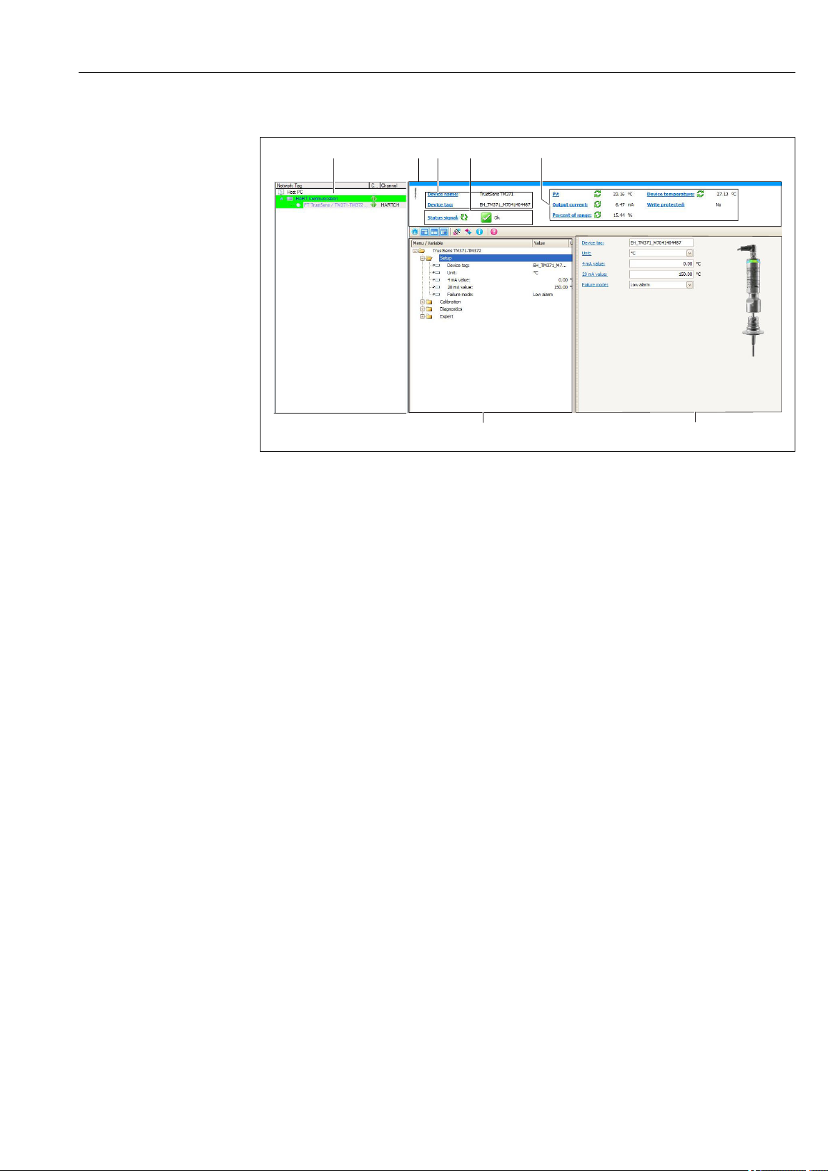
User interface
A0032334-EN
8 User interface with device information via HART®-communication
1 Network view
2 Header
3 Device tag and device name
4 Status area for the status signal
5 Measured values with general device information: PV, output current, percent of range, device temperature
6 Navigation area with operating menu structure
7 Display and input area
6.3.2 DeviceCare
Function scope
DeviceCare is a free configuration tool for Endress+Hauser devices. It supports devices with
the following protocols, provided a suitable device driver (DTM) is installed: HART,
PROFIBUS, FOUNDATION Fieldbus, Ethernet/IP, Modbus, CDI, ISS, IPC and PCP. The tool is
aimed at customers without a digital network in plants and workshops as well as Endress
+Hauser service technicians. The devices can be connected directly via a modem (point-topoint) or a bus system. DeviceCare is fast, easy and intuitive to use. It can run on a PC,
laptop or tablet with a Windows operating system.
Source for device description files
See data → 21
6.3.3 Field Xpert
Function scope
Field Xpert is an industrial PDA (personal digital assistant) with integrated touchscreen for
commissioning and maintaining field devices in explosion hazardous and non-hazardous
areas. It allows efficient configuration of FOUNDATION fieldbus, HART and WirelessHART
devices.
Source for device description files
See data → 21
Endress+Hauser 19
Page 20

Operability iTHERM TrustSens TM371, TM372
6.3.4 AMS Device Manager
Function scope
Program from Emerson Process Management for operating and configuring measuring
devices via the HART® protocol.
Source for device description files
See data → 21
6.3.5 SIMATIC PDM
Function scope
SIMATIC PDM is a standardized, manufacturer-independent program from Siemens for
the operation, configuration, maintenance and diagnosis of intelligent field devices via the
HART ® protocol.
Source for device description files
See data → 21
6.3.6 Field Communicator 375/475
Function scope
Industrial handheld terminal from Emerson Process Management for remote
configuration and measured value display via the HART ® protocol.
Source for device description files
See data → 21
20 Endress+Hauser
Page 21
iTHERM TrustSens TM371, TM372 System integration
7 System integration
7.1 Overview of device description files
Version data for the device
Firmware version 01.00.zz The firmware version can be found:
• on the nameplate → 1, 8
• in the operating menu: Diagnostics → Device
information → Firmware version
•
Please make sure to use the operating
instructions valid for the device. The
corresponding firmware versions for each
operating instructions can be found on its title
page.
Manufacturer ID (17) 0x11 Operating menu: Diagnostics → Device information →
Manufacturer ID
Device type 0x11CF Operating menu: Expert → Communication → HART
info → Device type
HART protocol revision 7.0 Operating menu: Expert → Communication → HART
info → HART revision
Device revision 1 • On the nameplate → 1, 8
• Operating menu: Expert → Communication → HART
info → Device revision
The suitable device driver software (DD/DTM) for the individual operating tools can be
obtained from different sources:
• www.endress.com --> Downloads --> Media Type: Software --> Software Type:
Application Software
• www.endress.com --> Products: individual product page e.g. TM371 --> Documents /
Manuals / Software: Electronic Data Description (EDD) or Device Type Manager (DTM).
• via DVD (contact your local Endress+Hauser sales center)
Endress+Hauser supports all common operating tools of different manufacturers (e.g.
Emerson Process Management, ABB, Siemens, Yokogawa, Honeywell and many more).
The Endress+Hauser operating tools FieldCare and Device care can also be obtained per
download (www. endress.com --> Downloads --> Media Type: Software --> Application
Software) or via optical data storage medium (DVD) from your local Endress+Hauser sales
center.
7.2 Measured variables via HART protocol
The measured values (device variables) are assigned to the device variables as follows:
Dynamic variable Device variable
Primary value (PV) Temperature
Secondary value (SV) Device temperature
Tertiary value (TV) Number of self-calibrations
Quaternary value (QV) Calibration deviation
Endress+Hauser 21
Page 22

System integration iTHERM TrustSens TM371, TM372
7.3
Supported HART® commands
The HART® protocol enables the transfer of measurement data and device data
between the HART® master and the field device. HART® masters such as the above
listed operating tools require an appropriate device driver software (DD or DTM) to
establish the data exchange. The data exchange is initiated via commands.
There are three different types of commands.
• Universal commands:
All HART® devices support and use universal commands. These are associated with the
following functionalities for example:
– Recognition of HART® devices
– Reading digital measured values
• Common practice commands:
Common practice commands offer functions which are supported and can be executed by
many but not all field devices.
• Device-specific commands:
These commands allow access to device-specific functions which are not HART
®
standard. Such commands access individual field device information.
Command No. Designation
Universal commands
0, Cmd0 Read unique identifier
1, Cmd001 Read primary variable
2, Cmd002 Read loop current and percent of range
3, Cmd003 Read dynamic variables and loop current
6, Cmd006 Write polling address
7, Cmd007 Read loop configuration
8, Cmd008 Read dynamic variable classifications
9, Cmd009 Read device variables with status
11, Cmd011 Read unique identifier associated with TAG
12, Cmd012 Read message
13, Cmd013 Read TAG, descriptor, date
14, Cmd014 Read primary variable transducer information
15, Cmd015 Read device information
16, Cmd016 Read final assembly number
17, Cmd017 Write message
18, Cmd018 Write TAG, descriptor, date
19, Cmd019 Write final assembly number
20, Cmd020 Read long TAG (32-byte TAG)
21, Cmd021 Read unique identifier associated with long TAG
22, Cmd022 Write long TAG (32-byte TAG)
38, Cmd038 Reset configuration changed flag
48, Cmd048 Read additional device status
Common practice commands
33, Cmd033 Read device variables
34, Cmd034 Write primary variable damping value
35, Cmd035 Write primary variable range values
40, Cmd040 Enter/Exit fixed current mode
22 Endress+Hauser
Page 23

iTHERM TrustSens TM371, TM372 System integration
Command No. Designation
42, Cmd042 Perform device reset
44, Cmd044 Write primary variable units
45, Cmd045 Trim loop current zero
46, Cmd046 Trim loop current gain
50, Cmd050 Read dynamic variable assignments
54, Cmd054 Read device variable information
59, Cmd059 Write number of response preambles
95, Cmd095 Read Device Communication Statistics
100, Cmd100 Write Primary Variable Alarm Code
516, Cmd516 Read Device Location
517, Cmd517 Write Device Location
518, Cmd518 Read Location Description
519, Cmd519 Write Location Description
520, Cmd520 Read Process Unit Tag
521, Cmd521 Write Process Unit Tag
523, Cmd523 Read Condensed Status Mapping Array
524, Cmd524 Write Condensed Status Mapping Array
525, Cmd525 Reset Condensed Status Mapping Array
526, Cmd526 Write Simulation Mode
527, Cmd527 Simulate Status Bit
Endress+Hauser 23
Page 24
Commissioning iTHERM TrustSens TM371, TM372
1
8 Commissioning
8.1 Function check
Before commissioning the device make sure that all final checks have been carried out:
• Checklist "Post-mounting check" , → 13
• Checklist "Post-connection check", → 15
8.2 Switching on the measuring device
Once the final checks have been successfully completed, it is time to switch on the supply
voltage. The device performs a number of internal test functions after power-up. This is
indicated by red LED-flashing. The device is operational after approx. 10 seconds in
normal operating mode. The LED on the device is illuminated green.
8.2.1 Display elements
1 LED signals for device status indication.
Function description of the different LED signals, see → 35
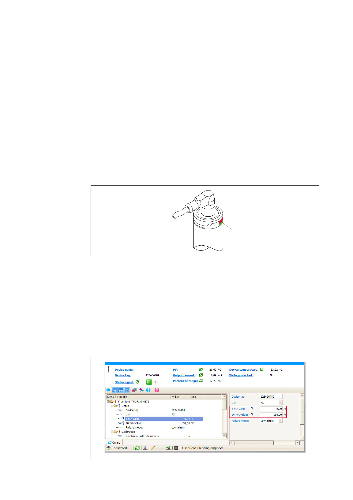
8.3 Configuring the measuring device
See 'Operating menu and parameter description'→ 74
8.3.1 Defining the measurement range
To configure the measurement range, enter the 4 mA value and the 20 mA value.
A0031589
A0034666-EN
24 Endress+Hauser
Page 25
iTHERM TrustSens TM371, TM372 Commissioning
2
1
Navigation
"Setup" menu → 4 mA value
"Setup" menu → 20 mA value
1. In the 4 mA value input window, enter the lower range value of your process
measurement range and press ENTER to confirm.
2. In the 20 mA value input window, enter the upper range value of your process
measurement range and press ENTER to confirm.
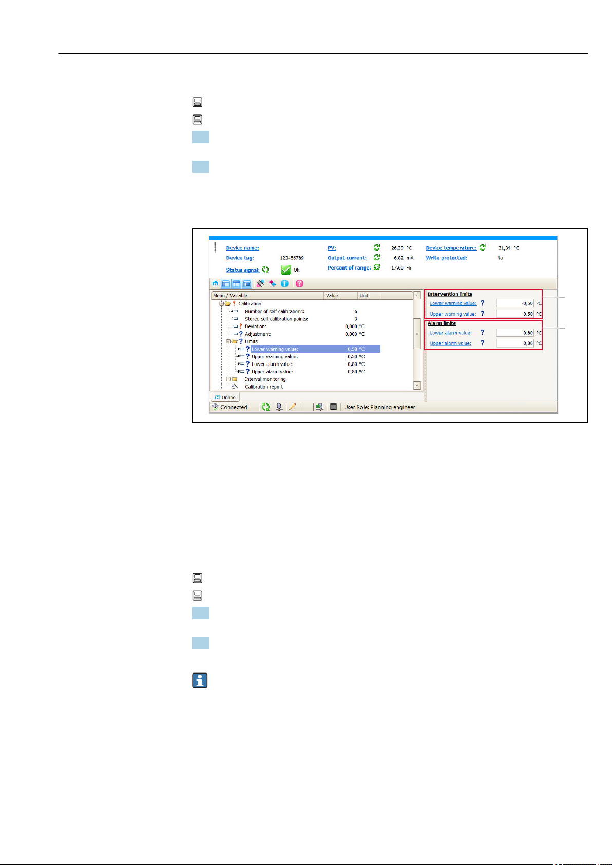
8.3.2 Defining the warning limits for the self-calibration
A0034668-EN
1 Values to be entered for the warning limits
2 Values to be entered for the alarm limits
Use this function to define the lower and upper warning limit. As a result of each selfcalibration the deviation between the reference sensor and the Pt100 sensor is being
determined. If this deviation exceeds the defined warning limit, the device will transmit
the defined status signal and show the defined diagnostic behavior via the LED. (Factory
setting = Warning - LED red flashes, diagnostic number 144. Measured value status =
Uncertain / Not limited).
Navigation
"Calibration" menu → Limits → Lower warning value
"Calibration" menu → Limits → Upper warning value
1. In the Lower warning value input window, enter the lower warning limit for the
self-calibration deviation and press ENTER to confirm.
2. In the Upper warning value input window, enter the upper warning limit for the
self-calibration deviation and press ENTER to confirm.
Please consider the maximum limited value range to be entered: ±0.35 °C (±0.67 °F).
→ 80
8.3.3 Defining the alarm limits for the self-calibration
Use this function to define the lower and upper alarm limit. As a result of each selfcalibration the deviation between the reference sensor and the Pt100 sensor is being
determined. If this deviation exceeds the defined alarm limit, the device will transmit the
defined status signal and show the defined diagnostic behavior via the LED. (Factory
setting = Warning - LED red flashes, diagnostic number 143. Measured value status =
Uncertain / Not limited.)
Endress+Hauser 25
Page 26
Commissioning iTHERM TrustSens TM371, TM372
1.
2.
Navigation
"Calibration" menu → Limits → Lower alarm value
"Calibration" menu → Limits → Upper alarm value
1. In the Lower alarm value input window, enter the lower limit for the self-calibration
deviation and press ENTER to confirm.
2. In the Upper alarm value input window, enter the upper warning limit for the selfcalibration deviation and press ENTER to confirm.
Please consider the maximum limited value range to be entered: ±0.35 °C (±0.67 °F).
→ 80
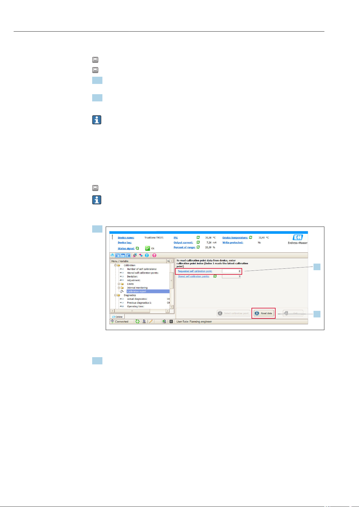
8.4 Creating a calibration report
The "calibration report" wizard guides you systematically through the process for creating a
calibration report for a pre-selected calibration point.
Navigation
"Calibration" menu → Calibration report
At least one stored self-calibration point must be in the device to start the online
wizard.
Configuration and creation of a calibration report
1.
To read the calibration point data from the device, enter the calibration point index.
Index 1 reads the latest calibration point.
2. Press READ DATA to confirm.
An overview of device information and calibration point data appears. See table
below for detailed information.
A0033678-EN
26 Endress+Hauser
Page 27
iTHERM TrustSens TM371, TM372 Commissioning
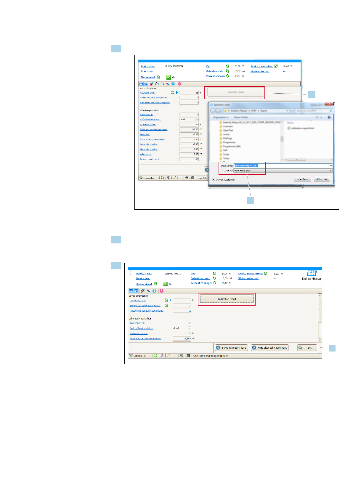
3.
4.
5.
3. Press CALIBRATION REPORT to continue.
A0033679-EN
Your file system explorer window appears. You are asked to save the calibration
report as a PDF file.
4. Enter a file name for the calibration report and select a memory location in your file
system.
The calibration report is just being saved on your file system.
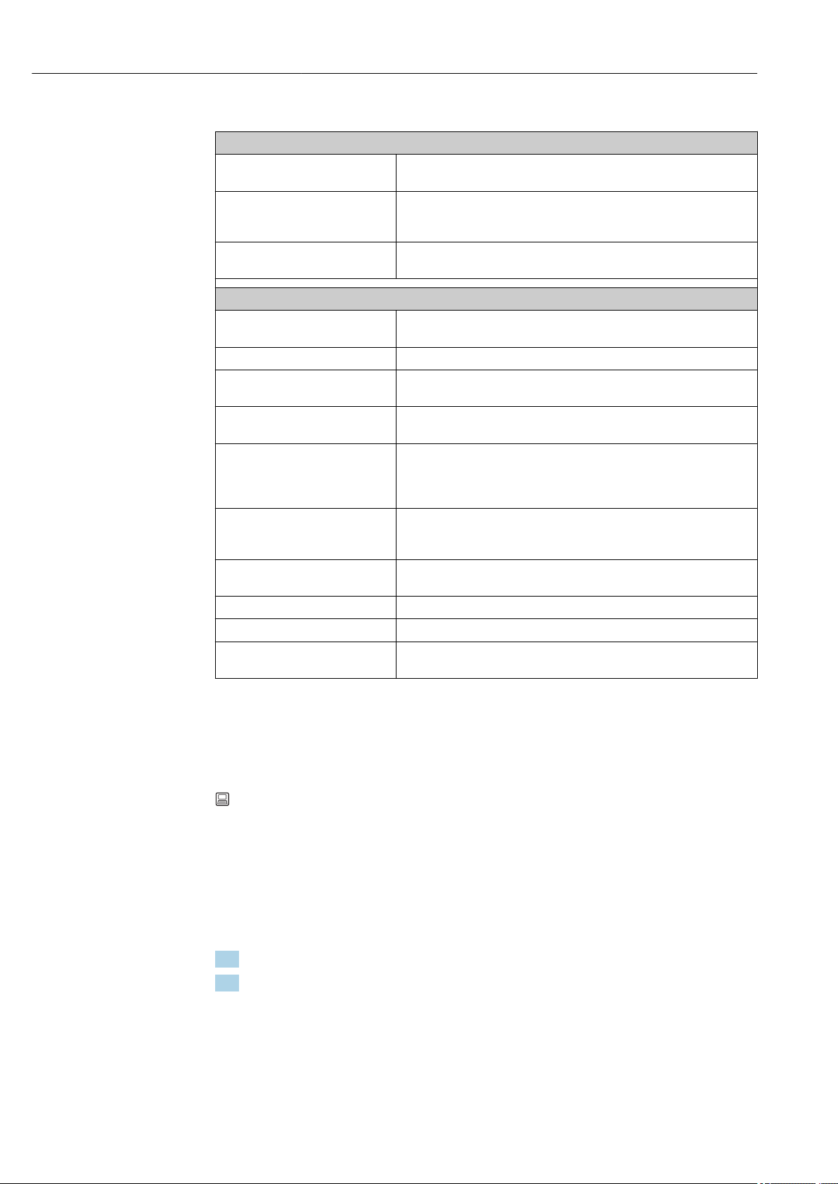
5.
A0033682-EN
Either press EXIT to end the calibration report wizard, press SELECT CALIBRATION
POINT to select another stored self-calibration point or press READ OLDER
CALIBRATION POINT to switch to the previous self-calibration point.
The creation of a self-calibration report is finished. The saved PDF-file can be opened to
read or to print the calibration report.
Endress+Hauser 27
Page 28
Commissioning iTHERM TrustSens TM371, TM372
Relevant self-calibration data for creating a report
Device information
Operating time Use this function to display the total count of hours when the device was
powered.
Stored self-calibration points Displays the amount of all stored self-calibration points. This device is
able to store 350 self-calibration points. As soon as the memory would
reach its limit, the oldest self-calibration point will be overwritten.
Requested self-calibration point Enter the number of the requested self-calibration point. The latest self-
calibration point always has the number "1".
Calibration point data
Calibration ID Use this number to identify a self-calibration point. Each number is
unique and is not editable.
Self-calibration status This function shows the validity of the self-calibration point data.
Operating hours This function displays the value of the operating hours counter of the
shown self-calibration point.
Measured temperature value This function displays the measured Pt100 temperature value at that
specific time of the self-calibration.
Deviation This function displays the measured Pt100 self-calibration deviation from
the reference temperature. The deviation is calculated as follows:
Self-calibration deviation = reference temperature - measured Pt100
temperature value + adjustment
Adjustment This function displays the adjustment value added to the measured Pt100
value. This influences the self-calibration deviation. → 80
New adjustment = Adjustment - deviation of last self-calibration point
Measurement uncertainty This functions displays the maximum measurement uncertainty at the
self-calibration temperature.
Lower alarm value This function displays the defined lower alarm limit value. → 81
Upper alarm value This function displays the defined upper alarm limit value. → 81
Device restart counter Displays the device restarts between now and when the displayed self-
calibration was executed.
8.5 Protecting settings from unauthorized access
Use this function to protect the device from unwanted changes.
Navigation
Expert menu → System → Administration → Define device write protection code
If the code is programmed into the device firmware it is saved in the device and the
operating tool displays the value 0 so that the defined write protection code is not openly
displayed for viewing.
User entry: 0 to 9 999
Factory default: 0 = write protection is not active.
To activate the write protection please go through the following steps:
1. Define a write protection in the Enter access code parameter.
2. Enter a code which does not correspond the the one which is defined in step 1.
The device is now write protected.
28 Endress+Hauser
Page 29
iTHERM TrustSens TM371, TM372 Commissioning
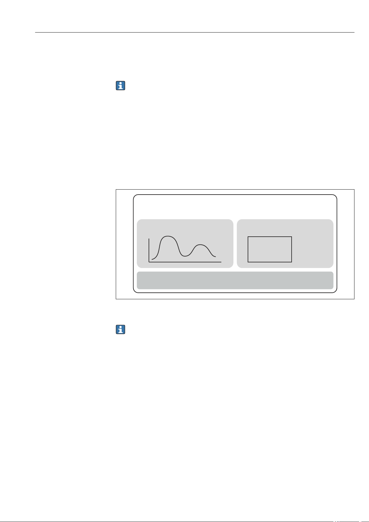
Heartbeat Diagnostics
Heartbeat Verification
Pass/Fail
}
· ......................
· ......................
· ......................
· ......................
· ......................
Heartbeat Monitoring
Heartbeat Technology
TM
Deactivate the write protection
Enter the defined code in the Enter access code parameter.
‣
The device is not write protected.
If the write protection code has been forgotten, it can be deleted or overwritten by the
service organization.
8.6 Advanced settings
The section contains a description of the additional parameters and technical data that are
available with the Heartbeat Verification and Heartbeat Monitoring application
packages.
8.6.1 Heartbeat modules
Overview
9 Heartbeat modules
The modules are available in all the device versions. The Heartbeat functionality is
available with the revised device driver software (DTM, version 1.11.zz and higher).
Short description of the modules
Heartbeat Diagnostics
Function
• Continuous self-monitoring of the device.
• Diagnostic messages output to
– a local display, optional
– an asset management system (e.g. FieldCare/DeviceCare)
– an automation system (e.g. PLC)
Advantages
• Device condition information is available immediately and processed in time.
• The status signals are classified in accordance with VDI/VDE 2650 and NAMUR
recommendation NE 107 and contain information about the cause of the error and
remedial action.
Detailed description
→ 30
A0020035
Endress+Hauser 29
Page 30

Commissioning iTHERM TrustSens TM371, TM372
Heartbeat Verification
Device functionality checked on demand
• Verification of the correct functioning of the measuring device within specifications.
• The verification result provides information about the condition of the device: "Passed" or
"Failed".
• The results are documented in a verification report.
• The automatically generated report supports the obligation to demonstrate compliance
with internal and external regulations, laws and standards.
• Verification is possible without interrupting the process.
Advantages
• No onsite presence is required to use the function.
• The DTM
1)
triggers verification in the device and interprets the results. No specific
knowledge is required on the part of the user.
• The verification report can be used to prove quality measures to a third party.
• Heartbeat Verification can replace other maintenance tasks (e.g. periodic check) or
extend the test intervals.
Detailed description
→ 31
Heartbeat Monitoring
Function
Calibration information is logged in addition to the verification parameters. 350
calibration points are saved in the device (FIFO memory).
Advantages
• Early detection of changes (trends) to ensure plant availability and product quality.
• Use of information for the proactive planning of measures (e.g. maintenance).
Detailed description
→ 33
8.6.2 Heartbeat Diagnostics
Device diagnostic messages, along with remedial measures, are displayed in the operating
tool (FieldCare/DeviceCare).
For information on using the diagnostic messages, see the "Diagnostics and
troubleshooting" section. → 35
Diagnostic message in the operating tool
1. Navigate to the "Diagnostics" menu.
The diagnostic event, along with the event text, is displayed in the Actual
diagnostics parameter.
1) DTM: Device Type Manager; controls device operation via DeviceCare, FieldCare, PACTware or a DTM-based control system.
30 Endress+Hauser
Page 31

iTHERM TrustSens TM371, TM372 Commissioning
2. On the right in the display area, hover the cursor over the "Actual diagnostics"
parameter.
A0037333-EN
A tool tip with remedy information for the diagnostic event appears.
8.6.3 Heartbeat Verification
Verification report
Creating the verification report using the wizard
The wizard to create a verification report is only available if the device is operated via
FieldCare, DeviceCare, PACTware or a DTM-based control system.
Navigation
Menu "Diagnostics → Heartbeat" → Heartbeat Verification
1. Press the Heartbeat Verification button.
The user-guided wizard appears.
2.
A0037334-EN
Endress+Hauser 31
Page 32

Commissioning iTHERM TrustSens TM371, TM372
3. Follow the instructions given by the wizard.
The wizard guides you through the entire process for creating the verification
report. The verification report can be saved in PDF and XML format.
The device must be in operation for at least 6 minutes before a verification can be
performed.
Content of the verification report
The verification report contains the results of the test objects: Passed or Failed is indicated
as the result.
Verification report: general information
Parameter Description/comments
Device information
System operator Name of the system operator; is defined when the verification report is created.
Location Location of the device within the plant; is defined when the verification report is
created.
Device tag Unique name for the measuring point so it can be identified quickly within the
plant. Is defined when commissioning the device.
Device name Displays the device name. It can also be found on the nameplate. It cannot be
changed.
Serial number Displays the serial number of the device. It can also be found on the nameplate.
It cannot be changed.
Order code Displays the order code of the device. It can also be found on the nameplate. It
cannot be changed.
Firmware version Displays the device firmware version installed. It cannot be changed.
Verification information
Operating time Indicates how long the device has been in operation up to this point.
Date/time Displays the current computer system time.
Comments Allows the user to enter optional comments, which appear in the verification
report.
Verification results
The test result for all the test
objects is given on the
subsequent pages. The
following results are possible:
• : Passed
• : Failed
Verification criteria for the test objects
Test object Verification criterion
Mainboard module
Electronics Checks the correct functioning of the electronics.
Memory content Checks the correct functioning of the data memory.
Supply voltage Checks the permitted supply voltage range.
Electronics temperature Checks the permitted electronics temperature range or device temperature
range.
32 Endress+Hauser
Page 33

iTHERM TrustSens TM371, TM372 Commissioning
Test object Verification criterion
Sensor module
Sensor Checks whether the sensor works as per the specifications.
Reference temperature Checks whether the reference sensor works as per the specifications.
Sensor drift warning limit
exceeded
Sensor drift alarm limit exceeded Checks whether the configured alarm limits are exceeded.
Sensor information
Number of self-calibrations Displays all the self-calibrations executed up to now. This value cannot be
Deviation Displays the deviation of the measured value from the reference
Adjustment of the measurement Displays the adjustment of the calibration deviation.
Monitoring parameters
Device temperature min: Displays the minimum electronics temperature measured in the past
Device temperature max: Displays the maximum electronics temperature measured in the past
Sensor min value: Displays the minimum temperature measured in the past at the sensor
Sensor max. value: Displays the maximum temperature measured in the past at the sensor
Checks whether the configured warning limits are exceeded.
reset.
temperature.
(peakhold indicator).
(peakhold indicator).
input (peakhold indicator).
input (peakhold indicator).
Summary of results
Overall
results
Displays the overall result of the verification. The verification report can be saved in PDF and XML
format. To save the report, click the Save results as PDF button or the Save results as XML
button.
If the verification fails, try again or contact the Service Organization.
8.6.4 Heartbeat Monitoring
Calibration information is logged in addition to the verification parameters.
HART variable Output Unit
PV Temperature °C/°F
SV Device temperature °C/°F
TV Calibration counter -
QV Calibration deviation °C/°F
Monitoring information can be read out and analyzed as described below:
A higher-level controller is configured in such a way that calibration deviations and the
calibration counter are saved when the calibration counter changes. This type of function
is supported by Endress+Hauser's Advanced Data Manager Memograph M RSG45, for
example. The following table provides a sample overview of the monitoring analysis using
the Field Data Manager software MS20:
Endress+Hauser 33
Page 34

Commissioning iTHERM TrustSens TM371, TM372
Time stamp Device name Category Text
25.07.2018 TrustSens 1 (example)Self-calibration EH_TM371_M7041504487: self-calibration
(ID=183)
Serial number: M7041504487
Device name: iTHERM TM371/372
Operating hours: 1626 h
Reference temperature: 118.67 °C
Measured temperature value: 118.68 °C
Deviation: 0.01 °C
Measuring uncertainty (k=2): 0.35 °C
Max. permitted deviation: -0.80 / +0.80 °C
Assessment
... ... ... ...
34 Endress+Hauser
Page 35

iTHERM TrustSens TM371, TM372 Diagnostics and troubleshooting
2
3
4
Commubox
PMC731: PIC0001
Online
1 >Group Select
2 PV 0.7 bar
HELP
SEND
HOME
1
1
9 Diagnostics and troubleshooting
9.1 Troubleshooting
Always start troubleshooting with the checklists below if faults occur after start up or
during operation. This takes you directly (via various queries) to the cause of the problem
and the appropriate remedial measures.
Due to its design, the device cannot be repaired. However, it is possible to send the
device back for examination. See the information in the "Return" section. → 41
General errors
Problem Possible cause Remedy
Device is not responding. Supply voltage range does not match
that specified on the nameplate.
M12 plug is not connected correctly,
wrong cable wiring.
Output current < 3.6 mA Device is defective. Replace the device.
HART communication is not
working.
Missing or incorrectly installed
communication resistor.
Apply correct voltage, see nameplate.
Check the wiring.
Install the communication resistor (250
Ω) correctly.
A0032326
1 TrustSens compact thermometer
2 HART® communication resistor, R =
≥ 250 Ω
3 PLC/DCS
4 Configuration examples: FieldCare
with Commubox, HART® handheld
communicator as well as via Field
Xpert SFX350/370
Commubox is not properly
Connect Commubox correctly .
connected.
9.2 Diagnostic information via LEDs
Position LEDs Function description
LED green (gn)
is illuminated
LED green (gn) is flashing
LED red (rd) and green
(gn) are flashing
alternating
A0031589
LED for device status
1
indication
LED red (rd) is flashing Presence of a diagnostic event: "Warning"
LED red (rd) is illuminated Presence of a diagnostic event: "Alarm"
Endress+Hauser 35
Voltage supply is correct. The device is
operational and the set limit values are met.
With a frequency 1 Hz: self-calibration
currently being performed.
With a frequency 5 Hz for 5 s: self-calibration
finished and valid, all process criteria were
within specifications. Calibration data stored.
Self-calibration process finished but not valid,
violation of necessary process criteria.
Calibration data not stored.
Page 36

Diagnostics and troubleshooting iTHERM TrustSens TM371, TM372
9.3 Diagnostic information
Status signal and diagnostic behavior can be configured manually.
Status signal - Digital information available via HART® communication
Letter/
symbol
F Failure The device or its periphery behaves in such a way that the measurement value is
C Function
S Out of
M Maintenance
Status signal Meaning of the status signal
no longer valid. This includes faults/failures which are caused by the process being
measured, but have an impact on the ability to perform a measurement e.g. “no
process signal” detected.
The device is deliberately serviced, configured, parameterized or is in simulation
check
specification
required
mode. A situation exists where the output signal does not represent the process
value and is therefore not valid.
The device is operating outside of its technical specifications or internal diagnostic
functions indicate that the current process conditions increase the measurement
uncertainty (i.e. during plant start-up or cleaning processes).
Deviation from normal operation, the device still works, but should be attended to
soon to ensure continued operation, e.g. build-up, corrosion, zero point
adjustment not possible or memory for data storage almost full.
1)
1) Valid for the default mappings to the diagnostic numbers
Diagnostic behavior - Analog information via current output and LED
Diagnostic behavior Meaning of the behavior
Alarm Measurement is interrupted. Mostly the measured data is invalid and the
configured failure current is set. A diagnostic message is generated.
Warning Usually, the device continues to measure. A diagnostic message is generated.
Disabled The diagnostic event is completely surpressed even if the device is not working
properly.
Diagnostics event and event text
Diagnostics event
Status signal Event number Event text
↓ ↓ ↓
Example 001 Device failure
3-digit number
The fault can be identified by means of the diagnostics event. The event text helps you by
providing information about the fault.
36 Endress+Hauser
Page 37

iTHERM TrustSens TM371, TM372 Diagnostics and troubleshooting
9.4 Overview of diagnostics events
Diagnostic events are assigned to a certain diagnostic number and a status signal. The user
can change this assignment for certain diagnostic events.
Example:
Settings Device behavior
Configuration example Diagnostic
number
Default setting 143 S Warning S Measured
Manual configuration:
Status signal S is switched to
F
Manual configuration:
diagnostic behavior
Warning is switched to
Alarm
Manual configuration:
Warning is switched to
Disabled
143 F Warning F Measured
143 S Alarm S Configured
143 S
Status
signal
1)
Diagnostic
behavior
(settings)
Disabled -
Status signal
(output via HART®
protocol)
2)
Output
current
value
value
failure
current
Last valid
measured
3)
value
PV, status LED
Measured value,
UNCERTAIN
Measured value,
UNCERTAIN
Measured value,
BAD
Last valid
measured value,
GOOD
Red is
flashing
Red is
flashing
Red is
illuminated
Green is
illuminated
1) Setting is not relevant.
2) Status signal is not indicated.
3) If there is no valid measured value, it is set to the failure current
Diagnostic
number
001 1 Device failure 1. Restart device.
004 2 Sensor defective Replace device. F
047 22 Sensor limit reached 1. Check sensor.
105 26 Manual calibration
143 21 Sensordrift Alarm
144 27 Sensordrift warning
221 29 Reference sensor
Priority Short text Remedy
2. Replace electronics.
2. Check process conditions.
1. Execute calibration and reset
interval expired
limit exceeded
limit exceeded
defective
3)
calibration interval.
2. Switch off calibration counter
1. Check self calibration alarm
limits.
2. Check value of adjustment.
3. Replace device
1. Check self calibration warning
limits.
2. Check value of adjustment.
3. Replace device
Replace device. M
Diagnostics
Not
1)
Diagnostic
behavior
from the
factory
Alarm
Warning
Status
signal
(factory
default)
F Alarm
S Warning
M Warning
S Warning
M Warning
Configurable
configurable
Configurable
Not
configurable
2)
Endress+Hauser 37
Page 38

Diagnostics and troubleshooting iTHERM TrustSens TM371, TM372
Diagnostic
number
Priority Short text Remedy
401 15 Factory reset active Factory reset in progress, please
wait.
402 16 Initialization active Initialization in progress, please
wait.
410 3 Data transfer failed 1. Check connection.
2. Repeat data transfer.
411 17 Up-/download active Up-/download in progress, please
wait.
435 5 Linearization faulty Check linearization. F
437 4 Configuration
Execute factory reset. F
incompatible
438 30 Dataset different 1. Check data set file.
2. Check device parameterization.
3. Download new device
parameterization.
485 18 Process variable
Deactivate simulation.
simulation activeSensor
491 19 Output simulation -
Deactivate simulation. C
current output
495 20 Diagnostic event
Deactivate simulation. C
simulation active
501 6 Wiring error
4)
Check wiring. F
Status
signal
(factory
default)
Configurable
1)
Diagnostic
behavior
from the
factory
Not
configurable
C
C
F
C
Warning
Warning
Alarm
Warning
Alarm
Alarm
M Warning
C Warning
Warning
Warning
Alarm
Configurable
Not
configurable
2)
531 6 Factory adjustment
missing
8 Factory adjustment
missing-Sensor
9 Factory adjustment
missing-Reference
1. Contact service organization.
2. Replace device.
sensor
10 Factory adjustment
missing-Current
output
537 11 Configuration 1. Check device configuration
2. Up- and download new
configuration
12 Configuration-Sensor 1. Check sensor configuration.
13 Configuration-
2. Check device configuration.
Reference sensor
14 Configuration-Current
output
1. Check application
2. Check the current output
parameterization
801 23 Supply voltage too low Increase supply voltage. S
825 24 Operating
temperature
1. Check ambient temperature.
2. Check process temperature.
F Alarm
F Alarm
Alarm
S
Warning
38 Endress+Hauser
Page 39

iTHERM TrustSens TM371, TM372 Diagnostics and troubleshooting
Not
1)
Diagnostic
behavior
from the
factory
Configurable
configurable
Status
Diagnostic
number
844 25 Process value out of
905 28 Self calibration
1) F, C, S, M, N can be configured
2) 'Alarm', 'Warning' and 'Disabled' can be configured
3) Reference sensor defective if temperature range of –45 to +200 °C (–49 to +392 °F) is exceeded. Temperature measurement continues, but self-
4) Leading error cause: CDI modem and loop are connected simultaneously, based on wrong connection (CDI modem or loop only) or defective cable
Priority Short text Remedy
1. Check process value.
specification
interval expired
calibration is permanently disabled.
plug.
2. Check application.
3. Check sensor.
1. Initiate self-calibration.
2. Deactivate self-calibration
interval monitoring.
3. Replace device
signal
(factory
default)
S Warning
M Warning
Configurable
configurable
2)
Not
9.5 Diagnostic list
If more than three diagnostic events occure simultaneously, only the messages with the
highest priorities are shown in the Diagnostics list. → 84 Characteristic feature of
the displayed priority is the status signal in the following order: F, C, S, M. If there are
several diagnostic events with the same status signal, the priority values from the table
above are used for ordering the diagnostic events, e.g.: F001 appears first, F501 appears
second and S047 appears last.
9.6 Event logbook
Diagnostic events that are no longer pending are shown in the Event logbook submenu.
→ 85
9.7 Firmware history
Revision history
The firmware version (FW) on the nameplate and in the Operating Instructions indicates
the device release: XX.YY.ZZ (example 01.02.01).
XX Change to main version. No longer compatible. Changes in the device
and Operating Instructions.
YY Change to functions and operation. Compatible. Changes in the
Operating Instructions.
ZZ Bug fixing. No changes to the Operating Instructions.
Date Firmware Version Modifications Documentation
09/17 01.00.zz Original firmware BA01581T/09
Endress+Hauser 39
Page 40

Maintenance iTHERM TrustSens TM371, TM372
10 Maintenance
In general, no specific maintenance is required for this device.
10.1 Cleaning
The sensor has to be cleaned as required. The cleaning can also be proceeded when the
device is installed (e.g. CIP Cleaning in Place / SIP Sterilization in Place). Care must be
taken to ensure that the sensor is not damaged during the cleaning.
The housing is resistant to typical cleaning agents from the outside. It passed the Ecolab
test.
40 Endress+Hauser
Page 41

iTHERM TrustSens TM371, TM372 Repair
11 Repair
Due to its design, the device cannot be repaired.
11.1 Spare parts
Currently available spare parts for your product can be found online at:
http://www.products.endress.com/spareparts_consumables. When ordering spare parts,
please quote the serial number of the device!
Type Order number
Plug screw fitting G1/2 1.4435 60022519
Spare Part Kit Press-Screw TK40 G1/4 d6 71215757
Spare Part Kit Press-Screw TK40 G1/2 d6 71217633
Weld-in adapter G3/4 d=50, 316L, 3.1 52018765
Weld-in adapter G3/4, d=29, 316L, 3.1 52028295
G1/2 metal to metal weld in adapter 60021387
Weld in adapter M12x1.5 316L&1.4435 71405560
O-ring 14.9x2.7 VMQ, FDA, 5 pieces 52021717
Weld-in adapter G3/4 d=55, 316L 52001052
Weld-in adapter G3/4, 316L, 3.1 52011897
O-ring 21.89x2.62 VMQ, FDA, 5 pcs. 52014473
Weld-in adapter G1, d=60, 316L 52001051
Weld-in adapter G1, d=60, 316L, 3.1 52011896
Weld-in adapter G1, d=53, 316L, 3.1 71093129
O-ring 28.17x3.53 VMQ, FDA, 5 pcs. 52014472
Adapter for Ingold connection 60017887
O-ring set for Ingold connection 60018911
Grip cap flexible yellow TPE 71275424
iTHERM TK40 compression fitting TK40-
Spare Part Kit sealing TK40 XPT0001-
iTHERM TT411 thermowell TT411-
11.2 Return
The measuring device must be returned if it is need of repair or a factory calibration, or if
the wrong measuring device has been delivered or ordered. Legal specifications require
Endress+Hauser, as an ISO-certified company, to follow certain procedures when handling
products that are in contact with the medium.
To ensure safe, swift and professional device returns, please refer to the procedure and
conditions for returning devices provided on the Endress+Hauser website at
http://www.endress.com/support/return-material
11.3 Disposal
The device contains electronic components and must therefore be disposed of as electronic
waste. Please pay particular attention to the national disposal regulations in your country.
Please seperate the different components according to their material consistence.
Endress+Hauser 41
Page 42

Accessories iTHERM TrustSens TM371, TM372
!30 (1.18)
16 (0.63)
34 (1.34)
15 (0.6)
G½”
M12x1.5
!7.6 (0.3)
!20 (0.8)
13 (0.51)
17 (0.67)
8 (0.31)
!18
(0.71)
G½”/
M12x1.5
37 (1.46)
AF22
G 1¼”
50 (1.97)
12 Accessories
12.1 Device-specific accessories
Device-specific accessories
Accessories Description
Welding boss with sealing taper (metal -
metal)
Welding boss for G½" and M12x1.5 thread
Metal-sealing; conical
Material of wetted parts: 316L/1.4435
Max. process pressure 16 bar (232 PSI)
Order number:
• 60021387 (G½")
• 71405560 (M12x1.5)
Dummy plug
A0006621
A0018236
Dummy plug for G½” or M12x1.5 conical metal-sealing welding boss
Material: SS 316L/1.4435
Order number:
• 60022519 (G½")
• 60021194 (M12x1.5)
A0009213-EN
Weld-in adapter for Ingold process
connections
Material of wetted parts: 316L/1.4435
Weight: 0.32 kg (0.7 lb)
Order number: 60017887
O-ring seal set
• Silicone O-ring in accordance with FDA CFR 21
• Maximum temperature: 230 °C (446 °F)
• Order number: 60018911
42 Endress+Hauser
A0008956
Page 43

iTHERM TrustSens TM371, TM372 Accessories
ø
26 (1.0)
25 (1.0)
ø
29 (1.1)
30 (1.2)
G
ISO 228
¾"
ø32 (1.3)
ø
50 (2.0)
26 (1.0)
21 (0.8)
ø
32 (1.3)
G ¾
ISO 228
"
26 (1.0)
ø
55 (2.2)
21 (0.8)
ø
32 (1.3)
G ¾
ISO 228
"
ø50 (2.0)
ø53 (2.1)
47.8 (1.9)
24.6 (1.0)
30°
21 (0.8)
ø41 (1.6)
G 1"
ISO 228
Weld-in adapter for FTL31/33/20,
pipe-mounting
A0008265
1) A seal is included in the delivery.
Weld-in adapter for FTL31/33/20,
vessel-mounting
G¾", d=29 mm, without flange
Material: 316L
Roughness in μm (μin): 1.5 (59.1)
Order number: 52028295 (with inspection certificate EN10204-3.1
material)
Order number seal (5-pc. set): silicone O-ring 52021717
compliant
G¾", d=50 mm, with flange
Material: 316L
Roughness in μm (μin): 0.8 (31.5)
Order number: 52018765 (with inspection certificate EN10204-3.1
material)
Order number seal (5-pc. set): silicone O-ring 52021717
compliant
EHEDG tested and 3-A marked
1)
, FDA-
1)
, FDA-
A0008810
1) A seal is included in the delivery.
Weld-in adapter for FTL50
A0008274
1) A seal is included in the delivery.
Weld-in adapter for FTL50
G¾", d=55 mm, with flange
Material: 316L
Roughness in μm (μin): 0.8 (31.5)
Order number: 52001052 (without inspection certificate
EN10204-3.1 material)
Order number: 52011897 (with inspection certificate EN10204-3.1
material)
Order number seal (5-pc. set): silicone O-ring 52014473
compliant
Order number weld-in dummy: MVT2L0692
EHEDG tested and 3-A marked
G1", d=53 mm, without flange
Material: 316L
Roughness in μm (μin): 0.8 (31.5)
Order number: 71093129 (with inspection certificate EN10204-3.1
material)
Order number seal (5-pc. set): silicone O-ring 52014472
compliant
Order number weld-in dummy: MVT2L0691
1)
, FDA-
1)
, FDA-
1) A seal is included in the delivery.
A0011927
Endress+Hauser 43
Page 44

Accessories iTHERM TrustSens TM371, TM372
ø41 (1.6)
G 1"
ISO 228
ø60 (2.4)
29.6 (1.2)
24.6 (1.0)
26 (1.02)
5 (0.2)
ø65 (2.56)
!D
20 (0.79)
35 (1.38)
Weld-in adapter for FTL50
A0008267
1) A seal is included in the delivery.
Weld-in adapter for FTL50
G1", d=60 mm, with flange
Material: 316L
Roughness in μm (μin): 0.8 (31.5)
Order number: 52001051 (without inspection certificate
EN10204-3.1 material)
Order number: 52011896 (with inspection certificate EN10204-3.1
material)
Order number seal (5-pc. set): silicone O-ring 52014472
compliant
Order number weld-in dummy: MVT2L0691
EHEDG tested and 3-A marked
G1", can be aligned
Material: 316L
Roughness in μm (μin): 0.8 (31.5)
Order number: 52001221 (without inspection certificate
EN10204-3.1 material)
Order number: 52011898 (with inspection certificate EN10204-3.1
material)
Order number seal (5-pc. set): silicone O-ring 52014424
compliant
Order number weld-in dummy: M40167
1)
, FDA-
1)
, FDA-
A0008272
1) A seal is included in the delivery.
Flexible handle cap to cover the
QuickNeck bottom part
Diameter ⌀D: 24 to 26 mm (0.94 to 1.02 in)
Material: Thermoplastic polyolefin - elastomer (TPE), free from
plasticizers
Maximum temperature: +150 °C (+302 °F)
Order number: 71275424
A0027201
Maximum process pressure for the weld-in adapters:
• 25 bar (362 PSI) at maximum 150 °C (302 °F)
• 40 bar (580 PSI) at maximum 100 °C (212 °F)
For more information on the weld-in adapters, see Technical Information (TI00426F/
00).
44 Endress+Hauser
Page 45

iTHERM TrustSens TM371, TM372 Accessories
USB
FieldCare/
DeviceCare
USB
USB
driver
1
2 (WH) nc
2
1 (BN) +
4
3 (BU) -
3
4 (BK) nc
1
2 (WH) nc
2
1 (BN) +
4
3 (BU) -
3
4 (BK) nc
A
B
USB
drivers
12.2 Communication-specific accessories
Configuration kit TXU10
Commubox FXA291
Cordset M12x1, angle plug
Configuration kit for CDI communication with PC-programmable
devices. Includes interface cable for PC with USB port and M12x1
coupling (Non-Ex area).
Order code: TXU10-BD
A0028635
Connects Endress+Hauser field devices with a CDI interface (=
Endress+Hauser Common Data Interface) and the USB port of a
computer or laptop (Non-Ex area and Ex area).
For details, see "Technical Information" TI00405C
A0034600
PVC cable, 4 x 0.34 mm² (22 AWG) with M12x1 coupling; angle
plug; screw plug; length 5 m (16.4 ft); IP69K
Order number: 52024216
Core colours:
• 1 = BN brown
• 2 = WH white
• 3 = BU blue
• 4 = BK black
A0020723
Cordset M12x1, straight
PVC cable, 4 x 0.34 mm² (22 AWG) with M12x1 coupling nut from
stainless steel; straight female connector type; screw plug; length 5
m (16.4 ft); IP69K
Order number: 71217708
Core colors:
• 1 = BN brown
• 2 = WH white
• 3 = BU blue
A0020725
• 4 = BK black
Commubox FXA195 HART
For intrinsically safe HART communication with FieldCare via the
USB interface.
For details, see "Technical Information" TI00404F
A0032846
HART Loop Converter HMX50 Is used to evaluate and convert dynamic HART process variables to
analog current signals or limit values.
For details, see "Technical Information" TI00429F and
Operating Instructions BA00371F
Fieldgate FXA320 Gateway for the remote monitoring of connected 4-20 mA
measuring devices via a Web browser.
For details, see "Technical Information" TI00025S and
Operating Instructions BA00053S
Fieldgate FXA520 Gateway for the remote diagnostics and remote configuration of
connected HART measuring devices via a Web browser.
For details, see "Technical Information" TI00025S and
Operating Instructions BA00051S
Endress+Hauser 45
Page 46

Accessories iTHERM TrustSens TM371, TM372
Field Xpert SFX350, 370 • Field Xpert is a powerful, compact industrial PDA based on the
Windows Embedded Handheld operating system and offering
integrated WLAN, USB, Bluetooth and infrared interfaces. This
allows it to be connected to HART and/or FOUNDATION Fieldbus
devices via a modem or gateway.
• SFX350 for configuration of field devices in Non-Ex areas
• SFX370 for configuration of field devices in Non-Ex areas and Ex
areas
For details, see Operating Instructions BA01202S
12.3 Service-specific accessories
Accessories Description
Applicator Software for selecting and sizing Endress+Hauser measuring devices:
• Calculation of all the necessary data for identifying the optimum measuring
device: e.g. pressure loss, accuracy or process connections.
• Graphic illustration of the calculation results
Administration, documentation and access to all project-related data and
parameters over the entire life cycle of a project.
Applicator is available:
Via the Internet: https://portal.endress.com/webapp/applicator
Configurator Product Configurator - the tool for individual product configuration
• Up-to-the-minute configuration data
• Depending on the device: Direct input of measuring point-specific information
such as measuring range or operating language
• Automatic verification of exclusion criteria
• Automatic creation of the order code and its breakdown in PDF or Excel output
format
• Ability to order directly in the Endress+Hauser Online Shop
The Configurator is available on the Endress+Hauser website: www.endress.com ->
Click "Corporate" -> Select your country -> Click "Products" -> Select the product
using the filters and the search field -> Open the product page -> The "Configure"
button to the right of the product image opens the Product Configurator.
W@M Life cycle management for your plant
W@M supports you with a wide range of software applications over the entire
process: from planning and procurement, to the installation, commissioning and
operation of the measuring devices. All the relevant device information, such as
the device status, spare parts and device-specific documentation, is available for
every device over the entire life cycle.
The application already contains the data of your Endress+Hauser device. Endress
+Hauser also takes care of maintaining and updating the data records.
W@M is available:
Via the Internet: www.endress.com/lifecyclemanagement
FieldCare SFE500 FDT-based plant asset management tool from Endress+Hauser.
It can configure all smart field units in your system and helps you manage them. By
using the status information, it is also a simple but effective way of checking their
status and condition.
For details, see Operating Instructions BA00027S and BA00065S
DeviceCare SFE100 Configuration tool for devices via fieldbus protocols and Endress+Hauser service
protocols.
DeviceCare is the tool developed by Endress+Hauser for the configuration of
Endress+Hauser devices. All smart devices in a plant can be configured via a pointto-point or point-to-bus connection. The user-friendly menus enable transparent
and intuitive access to the field devices.
For details, see Operating Instructions BA00027S
46 Endress+Hauser
Page 47

iTHERM TrustSens TM371, TM372 Technical Data
12.4 System components
Advanced Data Manager
Memograph M
RN221N Active barrier with power supply for safe separation of 4-20 mA standard signal
RNS221 Supply unit for powering two 2-wire measuring devices in the non-Ex area.
The Advanced Data Manager Memograph M is a flexible and powerful system for
organizing process values. The measured process values are clearly presented on
the display and logged safely, monitored for limit values and analyzed. Via
common communication protocols, the measured and calculated values can be
easily communicated to higher-level systems or individual plant modules can be
interconnected.
For details, see Technical Information TI01180R/09
circuits. Offers bidirectional HART transmission.
For details, see "Technical Information" TI00073R and Operating Instructions
BA00202R
Bidirectional communication is possible via the HART communication jacks.
For details, see "Technical Information" TI00081R and Brief Operating
Instructions KA00110R
13 Technical Data
13.1 Input
Measuring range
Pt100 thin-film (TF) –40 to +160 °C (–40 to +320 °F)
13.2 Output
Output signal
Failure information Failure information as per NAMUR NE43:
Analog output 4 to 20 mA
Digital output HART® protocol (revision 7)
Failure information is created if the measuring information is missing or not valid. A
complete list of all the errors occurring in the measuring system is created.
Underranging Linear decrease from 4.0 to 3.8 mA
Overranging Linear increase from 20.0 to 20.5 mA
Failure, e.g. sensor breakage, sensor shortcircuit
≤ 3.6 mA ("low") or ≥ 21 mA ("high"), can be selected
The "high" alarm setting can be set between 21.5 mA and
23 mA, thus providing the flexibility needed to meet the
requirements of various control systems.
Endress+Hauser 47
Page 48

Technical Data iTHERM TrustSens TM371, TM372
Ub
30 V
780
530
250
12 V
0
24.2 V
17.75 V
Supply voltage (V DC)
Load (Ω)
Load Maximum possible HART® communication resistance
R
b max.
output)
= (U
- 12 V) / 0.023 A (current
b max.
A0032387-EN
Linearization/transmission
Temperature-linear
behavior
Filter 1st order digital filter: 0 to 120 s, factory setting: 0 s (PV)
Protocol-specific data HART
Manufacturer ID 17 (0x11)
Device type ID 0x11CF
HART revision 7
Device description files (DTM, DD) Information and files at:
• www.endress.com/downloads
• www.fieldcommgroup.org
HART load Min. 250 Ω
HART device variables Measured value for PV (primary value)
Temperature
Measured values for SV, TV, QV (secondary, tertiary and quaternary
variable)
• SV: Device temperature
• TV: Calibration counter
• QV: Calibration deviation
Supported functions • Additional transmitter status
• NE107 diagnostics
Startup behavior / wireless HART data
Minimum start-up voltage 12 V
Start-up current 3.58 mA
Start-up time < 7 s, until the first valid measured value signal is present at the current
Minimum operating voltage 12 V
Multidrop current 4 mA
Lead time 0 s
13.3 Wiring
According to the 3-A Standard electrical connecting cables must be smooth,
DC
output
DC
corrosion-resistant and easy to clean.
48 Endress+Hauser
Page 49

iTHERM TrustSens TM371, TM372 Technical Data
Supply voltage Ub = 12 to 30 V
DC
The device may only be powered by a power supply unit with a limited energy electric
circuit in accordance with UL/EN/IEC 61010-1 chapter 9.4 or Class 2 according to UL
1310, "SELV or Class 2 cir-cuit".
Current consumption • I = 3.58 to 23 mA
• Minimum current consumption: I = 3.58 mA, multi-drop mode I =4 mA
• Maximum current consumption: I ≤ 23 mA
Overvoltage protection To protect against overvoltage in the power supply and signal/communication cables for
the thermometer electronics, Endress+Hauser offers the HAW562 surge arrester for DIN
rail mounting.
For more information see the Technical Information 'HAW562 Surge arrester'
TI01012K
13.4 Performance characteristics
Reference operating conditions
• Ambient temperature: 25 °C ± 5 °C (77 °F ± 9 °F)
• Supply voltage: 24 V
DC
Internal calibration point • 118 °C (244.4 °F) +1.2 K / –1.7 K
• Lowest possible calibration point = 116.3 °C (241.3 °F)
• Highest possible calibration point = 119.2 °C (246.6 °F)
The individual calibration point of each TrustSens device is indicated in the ex-works
calibration certificate enclosed with the shipment.
Measurement uncertainty The given uncertainty values include non-linearity and non-repeatability and correspond
to 2σ (95% confidence level according to the Gaussian distribution curve).
Uncertainty of self-calibration of digital output (HART® value) at the
calibration point.
Uncertainty of the
temperature sensor inclusive
digital output (HART® value)
at reference conditions in
delivery state.
Each iTHERM TrustSens
is calibrated and
matched by default
before shipment to
guarantee the given
accuracy.
Uncertainty of D/A converter (analog output current) 0.03 % of the measurement
Process temperature:
+20 to +135 °C (+68 to +275 °F)
+135 to +160 °C (+275 to +320 °F)
0 to +20 °C (+32 to +68 °F)
–20 to 0 °C (–4 to +32 °F)
–40 to –20 °C (–40 to –4 °F)
< 0.35 °C (0.63 °F)
< 0.22 °C (0.4 °F)
< 0.38 °C (0.68 °F)
< 0.27 °C (0.49 °F)
< 0.46 °C (0.83 °F)
< 0.8 °C (1.44 °F)
range
Endress+Hauser 49
Page 50

Technical Data iTHERM TrustSens TM371, TM372
Long-term drift
Influence of ambient temperature
Pt100 sensing element < 1000 ppm/1000 h
A/D converter (digital output - HART®) < 500 ppm/1000 h
D/A converter (analog output - current) < 100 ppm/1000 h
1) This would be detected by the self-calibration
1)
1)
Long-term drift decreases at an exponential rate over time. So it may not be
extrapolated in a linear way for time spans longer than the above given values.
A/D converter (digital output - HART®) at typical
operating conditions
A/D converter (digital output - HART®) at maximum
operating conditions
D/A converter (analog output - current) ≤ 30 ppm/°C (2σ), related to the deviation from the
< 0.05 K (0.09 °F)
< 0.15 K (0.27 °F)
reference temperature
Typical operating conditions
• Ambient temperature: 0 to +40 °C (+32 to +104 °F)
• Process temperature: 0 to +140 °C (+32 to +284 °F)
• Power supply: 18 to 24 V
DC
Influence of supply voltage According to IEC 61298-2:
A/D converter (digital output - HART®) at typical
operating conditions
D/A converter (analog output - current) < 10 ppm/V
1) Related to the deviation from the reference supply voltage
Sample calculation with Pt100, measuring range +20 to +135 °C (+68 to +275 °F), ambient
temperature +25 °C (+77 °F), supply voltage 24 V:
Measured error digital 0.220 °C (0.396 °F)
Measured error D/A = 0.03 % x 150 °C (302 °F) 0.045 °C (0.081 °F)
Measured error digital value (HART): 0.220 °C (0.396 °F)
Measured error analog value (current output): √(Measured error digital² +
Measured error D/A²)
Sample calculation with Pt100, measuring range +20 to +135 °C (+68 to +275 °F), ambient
temperature +35 °C (+95 °F), supply voltage 30 V:
Measured error digital 0.220 °C (0.396 °F)
Measured error D/A = 0.03 % x 150 °C (302 °F) 0.045 °C (0.081 °F)
Influence of ambient temperature (digital) 0.050 °C (0.090 °F)
Influence of ambient temperature (D/A) = (35 °C - 25 °C) x (30 ppm/°C x 150 °C) 0.045 °C (0.081 °F)
Influence of supply voltage (digital) = (30 V - 24 V) x 15 ppm/V x 150 °C 0.014 °C (0.025 °F)
Influence of supply voltage (D/A) = (30 V - 24 V) x 10 ppm/V x 150 °C 0.009 °C (0.016 °F)
< 15 ppm/V
1)
1)
0.225 °C (0.405 °F)
50 Endress+Hauser
Page 51

iTHERM TrustSens TM371, TM372 Technical Data
Measured error digital value (HART):
√(Measured error digital² + Influence of ambient temperature (digital)² + Influence
of supply voltage (digital)²
Measured error analog value (current output):
√(Measured error digital² + Measured error D/A² + Influence of ambient
temperature (digital)² + Influence of ambient temperature (D/A)² + Influence of
supply voltage (digital)² + Influence of supply voltage (D/A)²
0.226 °C (0.407 °F)
0.235 °C (0.423 °F)
Response time Tests in water at 0.4 m/s (1.3 ft/s), according to IEC 60751; 10 K temperature step
change. t63 / t90 are defined as the time that passes until the instrument output reaches
63% / 90% of the new value.
Response time with heat transfer paste
Protection tube Shape of tip Insert t
6 mm (0.24 in) Reduced 4.3 mm (0.17 in) x 20 mm (0.79 in) 3 mm (0.12 in) 2.9 s 5.4 s
9 mm (0.35 in)
12.7 mm (¹⁄₂ in)
1) Between the insert and the protection tube.
Reduced 5.3 mm (0.21 in) x 20 mm (0.79 in) 3 mm (0.12 in) 2.9 s 5.4 s
Reduced 5.3 mm (0.21 in) x 20 mm (0.79 in) 3 mm (0.12 in) 2.9 s 5.4 s
Reduced 8 mm (0.31 in) x 32 mm (1.26 in) 6 mm (0.24 in) 10.9 s 24.2 s
1)
63
Straight 6 mm (0.24 in) 9.1 s 17.9 s
Straight 6 mm (0.24 in) 10.9 s 24.2 s
t
90
Response time without heat transfer paste
Protection tube Shape of tip Insert t
Without
protection tube
6 mm (0.24 in) Reduced 4.3 mm (0.17 in) x 20 mm (0.79 in) 3 mm (0.12 in) 7.4 s 17.3 s
9 mm (0.35 in)
12.7 mm (¹⁄₂ in)
Reduced 5.3 mm (0.21 in) x 20 mm (0.79 in) 3 mm (0.12 in) 7.4 s 17.3 s
Reduced 5.3 mm (0.21 in) x 20 mm (0.79 in) 3 mm (0.12 in) 7.4 s 17.3 s
Reduced 8 mm (0.31 in) x 32 mm (1.26 in) 6 mm (0.24 in) 30.7 s 74.5 s
- 6 mm (0.24 in) 5.3 s 10.4 s
Straight 6 mm (0.24 in) 24.4 s 54.1 s
Straight 6 mm (0.24 in) 30.7 s 74.5 s
63
Calibration Calibration of thermometers
Calibration involves comparing the measured values of a device under test (DUT) with
those of a more precise calibration standard using a defined and reproducible
measurement method. The aim is to determine the deviation of the DUT's measured values
from the true value of the measured variable. Two different methods are used for
thermometers:
• Calibration at fixed-point temperatures, e.g. at the freezing point of water at 0 °C,
• Comparison calibration against a precise reference thermometer.
The thermometer to be calibrated must display the fixed point temperature or the
temperature of the reference thermometer as accurately as possible. Temperaturecontrolled calibration baths or special calibration furnaces with homogeneous distribution
of temperature are typically used for thermometer calibrations. The DUT and the reference
thermometer are placed closely together into the bath or furnace at a sufficient depth.
The measurement uncertainty can increase due to heat conduction errors and short
immersion lengths. The existing measurement uncertainty is listed on the individual
calibration certificate.
t
90
Endress+Hauser 51
Page 52

Technical Data iTHERM TrustSens TM371, TM372
For accredited calibrations according to IEC/ISO 17025, the measurement uncertainty
must not be twice as high as the accredited measurement uncertainty of the laboratory. If
the limit value is exceeded, only a factory calibration can be carried out.
For manual calibration in calibration baths the maximum immersion length of the
device ranges from the sensor tip to the lower part of the electronic housing. Do not
immerse the housing into the calibration bath!
A0032391
Self-calibration
The self-calibration procedure uses the Curie temperature (Tc) of a reference material as a
built-in temperature reference. A self-calibration is performed automatically, when the
process temperature (Tp) falls below the nominal Curie Temperature (Tc) of the device. At
the Curie temperature, a phase change of the reference material takes place, which is
associated with a change in its electrical properties. The electronics automatically detects
this change and simultaneously calculates the deviation of the measured Pt100temperature to the known, physically fixed Curie temperature. The TrustSens
thermometer is calibrated. A green flashing LED light indicates the ongoing selfcalibration process. Subsequently the thermometer electronics stores the results of this
calibration. The calibration data can be read via an asset management software like
FieldCare or DeviceCare. A self-calibration certificate can be created automatically. This
inline self calibration allows a continuous and repeated monitoring of changes to the
Pt100 sensor and to the electronics’ characteristics. As the inline calibration is being
performed under real ambient or process conditions (e.g. heating of electronics), the result
is closer to reality than a sensor calibration under laboratory conditions.
Process criteria for self-calibration
To ensure a valid self-calibration within the given measurement accuracy, the process
temperature characteristics needs to fulfil the criteria, which are checked by the device
automatically. Based on this, the device is ready to perform a self-calibration under the
following conditions:
– Process temperature > calibration temperature +3 °C (5.4 °F) for 25 s before cooling
down; t1 - t2.
– Cooling rate: 0.5 to 16.5 K/min (0.9 to 29.7 °F/min), while the process temperature
crosses the Curie temperature; t2 - t3 + 10 s.
The process temperature ideally declines continuously below 116 °C (240.8 °F). A valid
self-calibration process is done when the green LED flashes with a frequency 5 Hz for 5 s.
52 Endress+Hauser
Page 53

iTHERM TrustSens TM371, TM372 Technical Data
T / °C (°F)
t
123 °C
(253.4 °F)
> 25 s
< 116 °C (240.8 °F)
-16.5 K/min
(-29.7 °F/min)
t1
t2
1
t3
t3
116 °C
(240.8 °F)
-0.5 K/min
(-0.9 °F/min)
2
A0032839
10 Needed process temperature profile for self-calibration
1 Process temperature 123 °C (253.4 °F)
2 Allowed self-calibration range
Calibration monitoring
Available in conjunction with Advanced Data Manager Memograph M (RSG45). → 47
Application package:
• Up to 20 devices can be monitored via the HART interface
• Self-calibration data displayed on screen or via the Web server
• Generation of a calibration history
• Creation of a calibration protocol as an RTF file directly at the RSG45
• Evaluation, analysis and further processing of the calibration data using "Field Data
Manager" (FDM) analysis software
Insulation resistance Insulation resistance ≥ 100 MΩ at ambient temperature.
Insulation resistance between the terminals and the outer jacket is measured with a
minimum voltage of 100 V DC.
13.5 Environment
Ambient temperature range
Ambient temperature Ta–40 to +60 °C (–40 to +140 °F)
Maximum electronics
temperature T
–40 to +85 °C (–40 to +185 °F)
Storage temperature range T = –40 to +85 °C (–40 to +185 °F)
Climate class As per IEC 60654-1, Class Dx
Endress+Hauser 53
Page 54

Technical Data iTHERM TrustSens TM371, TM372
Degree of protection • IP54 for the version without protection tube provided for installation in an existing
protection tube
• IP67/68 for housing with LED status indication
• IP69K for housing without LED status indication and only if appropriate cord-set with
M12x1 coupling is connected. → 45
The specified rating IP67/68 or IP69K for the compact thermometer is only assured
when an approved M12 connector with a suitable IP rating is installed according to its
manual.
Shock and vibration resistance
Endress+Hauser temperature sensors meet the requirements of IEC 60751 which specify
shock and vibration resistance of 3g in the range from 10 to 500 Hz. This also applies for
the quick-fastening iTHERM QuickNeck.
Electromagnetic compatibility (EMC)
EMC to all relevant requirements of the IEC/EN 61326 - series and NAMUR
Recommendation EMC (NE21). For details, refer to the Declaration of Conformity. All tests
were passed both with and without ongoing HART® communication.
All EMC measurements were performed with a turn down (TD) = 5:1. Maximum
fluctuations during EMC- tests: < 1% of measuring span.
Interference immunity to IEC/EN 61326 - series, requirements for industrial areas.
Interference emission to IEC/EN 61326 - series, electrical equipment Class B.
13.6 Mechanical construction
Design, dimensions All dimensions in mm (in). The design of the thermometer depends on the protection tube
version used:
• Thermometer without a protection tube
• Diameter 6 mm (0.24 in)
• Diameter 9 mm (0.35 in)
• Diameter 12.7 mm (¹⁄₂ in)
• T-piece and corner-piece protection tube version as per DIN 11865 / ASME BPE 2012
for weld-in
Various dimensions, such as the immersion length U for example, are variable values
and are therefore indicated as items in the following dimensional drawings.
Variable dimensions:
Item Description
E Extension neck length, variable depending on the configuration or predefined for the version with
iTHERM QuickNeck
L Protection tube length (U+T)
B Protection tube bottom thickness: predefined, depends on protection tube version (see also the
individual table data)
T Length of protection tube shaft: variable or predefined, depends on protection tube version (see
also the individual table data)
U Immersion length: variable, depending on the configuration
⌀ID Insert diameter 6 mm (0.24 in) or 3 mm (0.12 in)
54 Endress+Hauser
Page 55

iTHERM TrustSens TM371, TM372 Technical Data
U
"31.5
(1.24)
71 (2.8)
U
E = 45
(1.77)
"31.5
(1.24)
"31.5
(1.24)
121 (4.76)
U
15 (0.6)
M24
x1.5
117 (4.61)
U
12 (0.47)
"31.5
(1.24)
G3/8"
U
"31.5
(1.24)
131 (5.16)
27 (1.06)
1 2 3 5
6
" ID
" ID " ID
" ID " ID
"31.5
(1.24)
121 (4.76)
" ID
"9
(0.35)
G¼“
U
E = 70 (2.56)
7
4
"31.5
(1.24)
121 (4.76)
" ID
"9
(0.35)
U
E
G3/8”
Without protection tube
For installation with compression fitting TK40 as process connection and the insert in direct contact with the process or in
an existing protection tube.
1 Thermometer without extension neck, for mounting with adjustable compression fitting TK40, spherically and cylindrically, only ⌀ID = 6 mm
2 Thermometer with extension neck, for mounting with compression fitting TK40 in fix position, only ⌀ID = 6 mm
3 Thermometer with compression fitting TK40 fixed by extension neck, connection thread M24x1.5, ⌀ID = 6 mm
4 Thermometer with neck tube TE411, G3/8" thread adapter nut
5 Thermometer with M24x1.5 female thread for protection tube connection, e.g. TT411, ⌀ID = 3 mm or 6 mm
6 Thermometer with G3/8" female thread for protection tube connection, e.g. TT411, ⌀ID = 3 mm or 6 mm
7 Thermometer with iTHERM QuickNeck top part for protection tube with QuickNeck connection, ⌀ID = 3 mm or 6 mm
Item Description
U
(protection
tube)
T
(protection
tube)
E Length of the extension neck at point of installation (provided one is available)
B
(protection
tube)
Pay attention to the following equations when calculating the immersion length U for immersion into a protection tube
TT411 already available:
Version 5 U = U
Version 3, 4, 6 and 7 U = U
Immersion length of the protection tube available at point of installation
Shaft length of protection tube available at point of installation
Base thickness of protection tube
(protection tube)
(protection tube)
+ T
(protection tube)
+ T
(protection tube)
+ E + 3 mm - B
+ 3 mm - B
(protection tube)
(protection tube)
A0031214
Endress+Hauser 55
Page 56

Technical Data iTHERM TrustSens TM371, TM372
!6
(0.24)
T
U
1
3
4
5
6
7
8
9
11
E = 34 (1.34)
117 (4.61)
131 (5.16)
15 (0.59)
E
T
U
2
B
10
With protection tube diameter 6 mm (0.24 in)
A0031254
1 Thermometer with extension neck and process connection as clamp version
2 Thermometer without extension neck and process connection as clamp version
3 Without process connection
4 Process connection version as spherical compression fitting TK40
5 Process connection version as metal sealing system M12x1
6 Process connection version as metal sealing system G½"
7 Process connection version as cylindrical weld-in adapter 12 x 40 mm
8 Process connection version as cylindrical weld-in adapter 30 x 40 mm
9 Process connection version as spherical-cylindrical weld-in adapter 30 x 40 mm
10 Process connection version as spherical weld-in adapter 25 x mm
11 Thermometer with quick-fastening iTHERM QuickNeck and process connection as sanitary connection (clamp
version)
G3/8" thread for protection tube connection
Item Version Length
Without extension neck -
Replaceable extenstion neck 9 mm (0.35 in) -
Extension neck E
Length of protection tube
1)
shaft T
iTHERM QuickNeck 34 mm (1.34 in)
Clamp DN12 according to ISO 2852 24 mm (0.94 in)
Clamp DN25/DN40 according to ISO 2852 21 mm (0.83 in)
Without process connection (only G3/8" thread), where
necessary with compression fitting TK40
Metal sealing system M12x1 46 mm (1.81 in)
Metal sealing system G½" 60 mm (2.36 in)
Cylindrical weld-in adapter 12 mm (0.47 in) 55 mm (2.17 in)
Cylindrical weld-in adapter 30 mm (1.18 in) 55 mm (2.17 in)
variable, depending
on the
configuration
12 mm (0.47 in)
56 Endress+Hauser
Page 57

iTHERM TrustSens TM371, TM372 Technical Data
Item Version Length
Spherical-cylindrical weld-in adapter 58 mm (2.28 in)
Spherical weld-in adapter 47 mm (1.85 in)
Tri-clamp (0.5"-0.75") 24 mm (0.94 in)
Microclamp (DN8-18) 23 mm (0.91 in)
Sanitary connection DN25/DN32/DN40 according to DIN
11851
Immersion length U Independent of the version
Bottom thickness B Reduced tip 4.3 mm (0.17 in) 2 mm (0.08 in)
1) Depends on the process connection
29 mm (1.14 in)
Variable, depending
on the
configuration
Endress+Hauser 57
Page 58

Technical Data iTHERM TrustSens TM371, TM372
U
!9
(0.35)
T
U
T = 85
(3.35)
1
2
!9 (0.35)
B
B
!15 (0.6)
3 4 5 6 7 8
159 10 11 12 13
121 (4.76)
131 (5.16)
14
With protection tube diameter 9 mm (0.35 in)
1 Thermometer with extension neck, process connection as clamp version
2 Process connection version as cylindrical weld-in adapter 30 x 40 mm
3 Process connection version as spherical-cylindrical weld-in adapter 30 x 40 mm
4 Process connection version as spherical weld-in adapter 25 x mm
5 Process connection version as sanitary connection according to DIN 11851
6 Process connection version as aseptic pipe union according to DIN 11864-1 Form A
7 Process connection version as metal sealing system G½"
8 Process connection version as thread according to ISO 228 for Liquiphant weld-in adapter
9 Process connection version APV Inline
10
Process connection version Varivent
11 Process connection version Ingold connection
12 Process connection to SMS 1147
13 Process connection version Neumo Biocontrol
14 Process adapter D45
15 Thermometer with quick-fastening iTHERM QuickNeck and process connection, as clamp version for example
®
A0031343
58 Endress+Hauser
Page 59

iTHERM TrustSens TM371, TM372 Technical Data
Item Version Length
Extension neck E No separate extension neck available -
Without quick-fastening iTHERM QuickNeck independent of the process connection 85 mm (3.35 in)
Without quick-fastening iTHERM QuickNeck in combination with Ingold connection
25 mm (0.98 in) x 46 mm (1.81 in)
With quick-fastening iTHERM QuickNeck, depending on the process connection:
SMS 1147, DN25 40 mm (1.57 in)
SMS 1147, DN38 41 mm (1.61 in)
SMS 1147, DN51 42 mm (1.65 in)
Varivent®, type F, D = 50 mm (1.97 in)
Varivent®, type N, D = 68 mm (2.67 in)
Varivent®, type B, D = 31 mm (1.22 in) 56 mm (2.2 in)
Thread G1" according to ISO 228 for Liquiphant weld-in adapter 77 mm (3.03 in)
Spherical-cylindrical weld-in adapter 70 mm (2.76 in)
Cylindrical weld-in adapter 67 mm (2.64 in)
Aseptic pipe union according to DIN11864-A, DN25
Length of protection
tube shaft T
Immersion length U Independent of the version
Bottom thickness B
Aseptic pipe union according to DIN11864-A, DN40
Sanitary connection according to DIN 11851, DN32
Sanitary connection according to DIN 11851, DN40
Sanitary connection according to DIN 11851, DN50
Clamp according to ISO 2852, DN12
Clamp according to ISO 2852, DN25 37 mm (1.46 in)
Clamp according to ISO 2852, DN40
Clamp according to ISO 2852, DN70
Microclamp (DN18) 47 mm (1.85 in)
Tri-clamp (0.75") 46 mm (1.81 in)
Ingold connection 25 mm (0.98 in) x 30 mm (1.18 in) 78 mm (3.07 in)
Ingold connection 25 mm (0.98 in) x 46 mm (1.81 in) 94 mm (3.7 in)
Metal sealing system G½" 77 mm (3.03 in)
APV-Inline, DN50 51 mm (2.01 in)
Reduced tip 5.3 mm (0.21 in)x 20 mm (0.79 in)
Straight tip
100 mm (3.94 in)
52 mm (2.05 in)
45 mm (1.77 in)
47 mm (1.85 in)
48 mm (1.89 in)
39 mm (1.54 in)Clamp according to ISO 2852, DN63.5
Variable, depending
on the configuration
2 mm (0.08 in)
Endress+Hauser 59
Page 60

Technical Data iTHERM TrustSens TM371, TM372
U
T
B
!12.7
(0.5)
B
T
U
43
1
5 6 7 8
E = 34 (1.34)
15 (0.59)
117 (4.61)
131 (5.16)
11 (0.43)
T
U
E
2
With protection tube diameter 12.7 mm (¹⁄₂ in)
A0031372
1 Thermometer with standard extension neck, thread and process connection as clamp version
2 Thermometer with extension neck and process connection as clamp version
3 Process connection version as cylindrical weld-in adapter 12.7 mm (½ in)
4 Process connection version as spherical weld-in adapter 25 mm (1 in)
5 Process connection version as sanitary connection according to DIN 11851
6 Thread according to ISO 228 for Liquiphant weld-in adapter
7
Process connection version Varivent
8 Thermometer with quick-fastening iTHERM QuickNeck and process connection, as clamp version for example
®
• G3/8" thread for protection tube connection
• Protection tube made from solid bar stock drilled for L ≤ 200 mm (7.87 in)
• Welded protection tube for L > 200 mm (7.87 in)
Item Version Length
Without extension neck -
9 mm (0.35 in) -
Extension neck E
Length of protection tube
shaft T
Immersion length U Independent of the process connection
Bottom thickness B
Replaceable extension neck
iTHERM QuickNeck 34 mm (1.34 in)
Weld-in adapter, cylindrical, 12.7 mm (¹⁄₂ in) 12 mm (0.47 in)
All other process connections 65 mm (2.56 in)
Reduced tip 5.3 mm (0.21 in)x 20 mm (0.79 in) 2 mm (0.079 in)
Reduced tip 8 mm (0.31 in)x 32 mm (1.26 in) 4 mm (0.16 in)
Straight tip 6 mm (0.24 in)
variable, depending on
the configuration
Variable, depending on
the configuration
60 Endress+Hauser
Page 61

iTHERM TrustSens TM371, TM372 Technical Data
1
2
3
4
117 (4.61)
82.7 (3.26)
E
15 (0.6)
131 (5.16)
11 (0.43)
0.7 (0.03)
E = 34 (1.34)
!4.5 (0.18)
11 (0.43)
G3/8" G3/8"
With tee- or elbow piece protection tube version
1 Thermometer with extension neck and tee-piece protection tube
2 Version with tee-piece protection tube
3 Version with elbow piece
4 Thermometer with quick-fastening iTHERM QuickNeck and elbow piece protection tube
Item Version Length
Without extension neck -
Replaceable extension neck 9 mm (0.35 in) -
Extension neck E
iTHERM QuickNeck 34 mm (1.34 in)
Bottom thickness B Independent of the version 0.7 mm (0.03 in)
Immersion length U Independent of the version 82.7 mm (3.26 in)
variable, depending
on the
configuration
• Pipe sizes according to DIN11865 series A (DIN), B (ISO) and C (ASME BPE)
• Nominal diameters > DN25, with 3-A symbol
• IP69K protection class
• Material 1.4435+316L, Delta ferrite content <0.5%
• Temperature measurement range: –60 to +200 °C (–76 to +392 °F)
• Pressure range: PN25 according to DIN11865
Due to the small immersion length U in pipes with a small nominal diamter, the use
of iTHERM QuickSens inserts is recommended.
A0031515
Endress+Hauser 61
Page 62

Technical Data iTHERM TrustSens TM371, TM372
Possible combinations of the protection tube versions with the available process
connections and quick-fastening iTHERM QuickNeck
Process connection and size
Without process connection (for installation with
compression fitting)
Protection tube diameter
6 mm (0.24 in)
2)
9 mm (0.35 in) 12.7 mm (¹⁄₂ in)
- - -
iTHERM QuickNeck for 9 mm
2)
(0.35 in)
Process adapter D45 - - -
Weld-in adapter
Cylindrical 12.7 mm (0.5 in) - - -
Cylindrical 30 x 40 mm
-
Cylindrical 12 x 40 mm - - -
Spherical-cylindrical 30 x 40 mm -
Spherical 25 mm (0.98 in) -
Clamp according to ISO 2852
Microclamp/Tri-clamp DN18 (0.75 in)
-
DN12 - 21.3
DN25 -38 (1 - 1.5 in)
DN40 - 51 (2 in)
DN63.5 (2.5 in)
-
DN70 - 76.5 (3 in)
Sanitary connection according to DIN 11851
DN25
DN32, DN40
DN50 -
Aseptic pipe union according to DIN 11864-1 Form A
DN25, DN40 - -
Metal sealing system
M12x1
-
-
G½"
Thread according to ISO 228 for Liquiphant weld-in adapter
G¾" for FTL31/33/20
G¾" for FTL50 -
-
G1" for FTL50
APV Inline
DN50 - -
Varivent
®
Type B, 31 mm; Type F, 50 mm ; Type N, 68 mm -
Ingold connection
25 x 30 mm or 25 x 46 mm - -
SMS 1147
DN25, DN38, DN51 - -
1)
-
-
-
62 Endress+Hauser
Page 63

iTHERM TrustSens TM371, TM372 Technical Data
Process connection and size
6 mm (0.24 in)
Neumo Biocontrol
D25 PN16, D50 PN16, D65 PN16 - - -
1) In the case of 6 mm (0.24 in) and 12.7 mm (½ in) diameters, the iTHERM QuickNeck is available for all process connection versions.
2) All versions available with iTHERM QuickNeck
Protection tube diameter
2)
9 mm (0.35 in) 12.7 mm (¹⁄₂ in)
iTHERM QuickNeck for 9 mm
2)
(0.35 in)
1)
Weight 0.2 to 2.5 kg (0.44 to 5.5 lbs) for standard options.
Material The temperatures for continuous operation specified in the following table are only
intended as reference values for use of the various materials in air and without any
significant compressive load. The maximum operating temperatures can be reduced
considerably in cases where abnormal conditions such as high mechanical load occur or in
aggressive media.
Recommended
Designation Short form
AISI 316L
(corresponds to
1.4404
or 1.4435)
1.4435+316L, delta
ferrite < 1% or <
0.5%
X2CrNiMo17-13-2,
X2CrNiMo18-14-3
With regard to analytical limits, the specifications of both materials (1.4435 and 316L)
are met simultaneously. In addition, the delta ferrite content of the wetted parts is
limited to <1% - including the welding seams (following Basel Standard II); or <0.5%
max. temperature
for continuous use
in air
650 °C (1 202 °F)
1)
Properties
• Austenitic, stainless steel
• High corrosion resistance in general
• Particularly high corrosion resistance in
chlorine-based and acidic, non-oxidizing
atmospheres through the addition of
molybdenum (e.g. phosphoric and
sulfuric acids, acetic and tartaric acids
with a low concentration)
• Increased resistance to intergranular
corrosion and pitting
Surface roughness
1) Can be used to a limited extent up to 800 °C (1472 °F) for low compressive loads and in non-corrosive
media. Contact your Endress+Hauser sales team for further information.
Values for wetted surfaces:
Mechanically polished surface Ra ≤ 0.76 µm (30 µin)
Mechanically polished surface
Mechanically polished surface and electropolished Ra ≤ 0.38 µm (15 µin)+ electropolished
1) Exception: internal welding seams of the tee- and elbow pieces
2) Not compliant with ASME BPE
1)
2)
Ra ≤ 0.38 µm (15 µin)
Endress+Hauser 63
Page 64

Technical Data iTHERM TrustSens TM371, TM372
!d
U
U
U
h
!d
!d
h
!d
h
!d
1 2
3
4
5
U
T
U
T
T
T
h
A
B
U
!d
!D
1
2
R0.4
R0.4
!i
!a
Protection tube Process connections
All dimensions in mm (in).
For welding in
Type Version Dimensions Technical properties
Weld-in adapter
1: Cylindrical
2: Cylindrical
3: Cylindrical d x h = 30 mm (1.18 in) x 40 mm (1.57 in)
4: Spherical-
cylindrical
5: Spherical d = 25 mm (0.98 in)
1)
d = 12.7 mm (¹⁄₂ in), U = immersion length
from lower edge of thread,
T = 12 mm (0.47 in)
2)
d x h = 12 mm (0.47 in) x 40 mm (1.57 in),
T = 55 mm (2.17 in)
d x h = 30 mm (1.18 in) x 40 mm (1.57 in)
h = 24 mm (0.94 in)
• P
depends on the weld-in
max.
process
• 3-A marked and EHEDG
certification
• ASME BPE compliance
1) For protection tube 12.7 mm (½ in)
2) For protection tube 6 mm (0.24 in)
Releasable process connection
Sanitary connection according to DIN 11851
1 Centering ring
2 Sealing ring
1)
Version
DN25
DN32 50 mm
A0009569
Type Technical properties
• 3-A marked and EHEDG
certification (only with
EHEDG-certified and selfcentering sealing ring).
• ASME BPE compliance
A0009561
Dimensions
D A B i a
44 mm
(1.73 in)
(1.97 in)
30 mm
(1.18 in)
36 mm
(1.42 in)
10 mm
(0.39 in)
10 mm
(0.39 in)
26 mm
(1.02 in)
32 mm
(1.26 in)
29 mm
(1.14 in)
35 mm
(1.38 in)
40 bar (580 psi)
40 bar (580 psi)
P
max.
64 Endress+Hauser
Page 65

iTHERM TrustSens TM371, TM372 Technical Data
!D
h
U
!d
!i
!a
!D
U
!d
!a
!d
U
!D
R0.8
R0.5
0.8 ± 0.1
2.16 ± 0.1
R1.2
R0.8
0.4
1.6
A
A: Microclamp
A: Tri-clamp
Type Technical properties
DN40 56 mm
(2.2 in)
DN50 68 mm
(2.68 in)
1) Pipes in accordance with DIN 11850
42 mm
(1.65 in)
54 mm
(2.13 in)
10 mm
(0.39 in)
11 mm
(0.43 in)
38 mm
(1.5 in)
50 mm
(1.97 in)
41 mm
(1.61 in)
53 mm
(2.1 in)
40 bar (580 psi)
25 bar (363 psi)
Type Version
Aseptic pipe union according to DIN
11864-1, Form A
Type
Clamp according to ISO 2852
A0009562
DN8-18 (0.5"-0.75")
Dimensions
d D i a h
DN25 26 mm
(1.02 in)
DN40 38 mm
(1.5 in)
42.9 mm
(1.7 in)
54.9 mm
(2.16 in)
26 mm
(1.02 in)
38 mm
(1.5 in)
29 mm
(1.14 in)
41 mm
(1.61 in)
9 mm
(0.35 in)
10 mm
(0.39 in)
Version Dimensions
1)
d:
Microclamp
2)
3)
D a
-
25 mm (0.98 in)
Tri-clamp DN8-18
(0.5"-0.75")
DN12-21.3 34 mm (1.34 in)
DN25-38 (1"-1.5") 50.5 mm (1.99 in)
-
16 to 25.3 mm
(0.63 to 0.99 in)
29 to 42.4 mm
(1.14 to 1.67 in)
DN40-51 (2") 64 mm (2.52 in) 44.8 to 55.8 mm
(1.76 to 2.2 in)
DN63.5 (2.5") 77.5 mm (3.05 in) 68.9 to 75.8 mm
(2.71 to 2.98 in)
DN70-76.5 (3") 91 mm (3.58 in) > 75.8 mm (2.98 in) • P
Technical properties
• P
= 40 bar (580 psi)
max.
• 3-A marked and EHEDG
certification
• ASME BPE compliance
Technical properties
• P
= 16 bar (232 psi),
max.
depends on clamp ring and
suitable seal
• 3-A marked
• P
= 16 bar (232 psi),
max.
depends on clamp ring and
suitable seal
• 3-A marked and EHEDG
certification (combined with
Hyjoin PEEK/stainless steel
seal or Dupont de Nemours
Kalrez/stainless steel seal)
• ASME BPE compliance
= 16 bar (232 psi),
max.
depends on clamp ring and
suitable seal
• 3-A marked
• ASME BPE compliance
4)
A0009566
A Different seal geometries for
1) Pipes in accordance with ISO 2037 and BS 4825 Part 1
2) Microclamp (not in ISO 2852); no standard pipes
3) DN8 (0.5") only possible with protection tube diameter = 6 mm (0.24 in)
Microclamp and Tri-clamp
4) Not for DN12-21.3
Endress+Hauser 65
Page 66

Technical Data iTHERM TrustSens TM371, TM372
U
14
(0.55)
22 (0.87)
M12
1.5x
!10
(0.4)
8 (0.3)
!6
(¼)
G3/8"
T = 46 (1.81)
20°
U
14
(0.55)
37 (1.46)
G½”
!18
(0.71)
8 (0.31)
!6 (¼)
G3/8"
T = 60 (2.36)
22.5°
U
14
(0.55)
37 (1.46)
G½”
"18 (0.71)
8 (0.31)
"9 (0.35)
T
45°
U
35 (1.38)
20
(0.79)
5 (0.20)
!45 (1.77)
!50 (1.97)
U
L1
1
G
A
Type Version Technical properties
Metal sealing system
M12x1.5
G½"
Protection tube diameter
6 mm (0.24 in)
P
= 16 bar (232 psi)
max.
Maximum torque =
10 Nm (7.38 lbf ft)
A0009574
-
Type Version Technical properties
Process adapter
D45 • 3-A marked
A0020856
Protection tube diameter
9 mm (0.35 in)
A0009571
P
= 16 bar (232 psi)
max.
Maximum torque =
10 Nm (7.38 lbf ft)
• EHEDG certification
A0034881
Dimensions
Type Version G
Thread according to ISO 228 (for weld-in
adapter)
66 Endress+Hauser
A0009572
G¾" for
FTL31/33/20
adapter
G¾" for FTL50
adapter
G1" for FTL50-
adapter
L1 thread
length
16 mm
(0.63 in)
18.6 mm
(0.73 in)
A 1 (SW/AF)
25.5 mm (1 in) 32
29.5 mm
(1.16 in)
41
Technical properties
• P
= 25 bar (362 psi) at
max.
max. 150 °C (302 °F)
• P
= 40 bar (580 psi) at
max.
max. 100 °C (212 °F)
• 3-A marked and EHEDG
certification
• ASME BPE compliance
Page 67

iTHERM TrustSens TM371, TM372 Technical Data
h
!d
M
!A
!B
U
U
!D
!B
!A
h
U
!D
!i
!a
Type Version
APV Inline
A0018435
Type Version
®
Varivent
d A B M h
DN50
69 mm
(2.72 in)
D A B h P
Type B 31 mm
(1.22 in)
Type F 50 mm
(1.97 in)
Type N 68 mm
(2.67 in)
Dimensions
Technical properties
• P
= 25 bar (362 psi)
99.5 mm
(3.92 in)
82 mm
(3.23 in)
2xM8
19 mm
(0.75 in)
max.
• 3-A marked and EHEDG
certification
• ASME BPE compliance
Dimensions Technical properties
max.
105 mm
(4.13 in)
145 mm
(5.71 in)
165 mm
(6.5 in)
- 22 mm
135 mm
(5.31 in)
155 mm
(6.1 in)
(0.87 in)
24 mm
(0.95 in)
24.5 mm
(0.96 in)
10 bar
(145 psi)
• 3-A marked and EHEDG
certification
• ASME BPE compliance
A0021307
The VARINLINE® housing connection flange is suitable for weld-in into the conical or torispherical head in tanks or containers with a small
diameter (≤ 1.6 m (5.25 ft)) and up to a wall thickness of 8 mm (0.31 in).
Type Technical properties
Varivent® for VARINLINE® housing for installation in pipes
• 3-A marked and EHEDG
certification
• ASME BPE compliance
A0009564
Dimensions
Version
D i a
P
max.
DN40: 38 mm (1.5 in) DN40: 41 mm (1.61 in)
DN50: 50 mm (1.97 in) DN50: 53 mm (2.1 in)
DN40 to DN65:
16 bar (232 psi)
DN65: 66 mm (2.6 in) DN65: 70 mm (2.76 in)
Type N, according to DIN
11866, series A
Endress+Hauser 67
68 mm (2.67 in)
DN80: 81 mm (3.2 in) DN80: 85 mm (3.35 in)
DN100: 100 mm (3.94 in) DN100: 104 mm (4.1 in)
DN125: 125 mm (4.92 in) DN125: 129 mm (5.08 in)
DN150: 150 mm (5.9 in) DN150: 154 mm (6.06 in)
DN80 to DN150:
10 bar (145 psi)
Page 68

Technical Data iTHERM TrustSens TM371, TM372
!D
!3.1
(0.12)
!4.5 (0.18)
G3/8”
L
!18 (0.71)
s
83 (3.26)
0.7 (0.03)
Version
Type N, according to EN
ISO 1127, series B
Type N, according to DIN
11866, series C
Type N, according to DIN
11866, series C
68 mm (2.67 in)
68 mm (2.67 in)
68 mm (2.67 in)
Advanced tee-piece (no welds, no dead legs)
Type Version
Tee-piece for weld-in as per DIN 11865
(part A, B and C)
A0035898
Dimensions
D i a
38.4 mm (1.51 in) 42.4 mm (1.67 in)
44.3 mm (1.75 in) 48.3 mm (1.9 in)
56.3 mm (2.22 in) 60.3 mm (2.37 in)
72.1 mm (2.84 in) 76.1 mm (3 in)
82.9 mm (3.26 in) 42.4 mm (3.5 in)
108.3 mm (4.26 in) 114.3 mm (4.5 in)
OD 1½": 34.9 mm (1.37 in) OD 1½": 38.1 mm (1.5 in)
OD 2": 47.2 mm (1.86 in) OD 2": 50.8 mm (2 in)
OD 2½": 60.2 mm (2.37 in) OD 2½": 63.5 mm (2.5 in)
OD 3": 73 mm (2.87 in) OD 3": 76.2 mm (3 in)
OD 4": 97.6 mm (3.84 in) OD 4": 101.6 mm (4 in)
Dimensions in mm (in)
D L s
Part A DN10 PN25 13 mm
(0.51 in)
DN15 PN25 19 mm
(0.75 in)
DN20 PN25 23 mm
(0.91 in)
DN25 PN25 29 mm
(1.14 in)
DN32 PN25 32 mm
(1.26 in)
Part B DN13,5 PN25 13.5 mm
(0.53 in)
DN17,2 PN25 17.2 mm
DN21,3 PN25 21.3 mm
DN26,9 PN25 26.9 mm
DN33,7 PN25 33.7 mm
Part
DN12,7 PN25
2)
C
(½")
DN19,05
PN25 (¾")
DN25,4 PN25
(1")
DN38,1 PN25
(1½")
(0.68 in)
(0.84 in)
(1.06 in)
(1.33 in)
12.7 mm
(0.5 in)
19.05 mm
(0.75 in)
25.4 mm
(1 in)
38.1 mm
(1.5 in)
48 mm
(1.89 in)
1)
1.5 mm
(0.06 in)
1.6 mm
(0.063 in)
2 mm
(0.08 in)
1.65 mm
(0.065 in)
P
max.
42.4 mm (1.67 in) to
60.3 mm (2.37 in):
16 bar (232 psi)
76.1 mm (3 in) to
114.3 mm (4.5 in):
10 bar (145 psi)
OD 1½" to OD 2½":
16 bar (232 psi)
OD 3" to OD 4": 10 bar (145 psi)
Technical properties
• P
= 25 bar (362 psi)
max.
• 3-A marked for > DN25
1) Wall thickness
2) Dimensions as per ASME BPE 2012
68 Endress+Hauser
Page 69

iTHERM TrustSens TM371, TM372 Technical Data
!D
!3.1
(0.12)
83 (3.26)
0.7 (0.03)
!4.5
(0.18)
G3/8”
L1
L2
!D
U
x
4
(0.16)
h
!D
G1¼“
Advanced elbow piece (no welds, no dead legs)
Type Version
Elbow piece for weld-in as per DIN 11865
(part A, B and C)
A0035899
D L1 L2 s
Part A DN10 PN25 13 mm
(0.51 in)
DN15 PN25 19 mm
(0.75 in)
DN20 PN25 23 mm
(0.91 in)
DN25 PN25 29 mm
(1.14 in)
DN32 PN25 35 mm
(1.38 in)
Part B DN13,5
PN25
DN17,2
PN25
DN21,3
PN25
DN26,9
PN25
DN33,7
PN25
Part C DN12,7
PN25 (½")
DN19,05
PN25 (¾")
DN25,4
PN25 (1")
DN38,1
PN25 (1½")
2)
13.5 mm
(0.53 in)
17.2 mm
(0.68 in)
21.3 mm
(0.84 in)
26.9 mm
(1.06 in)
33.7 mm
(1.33 in)
12.7 mm
(0.5 in)
19.05 mm
(0.75 in)
25.4 mm
(1 in)
38.1 mm
(1.5 in)
Dimensions
24 mm
(0.95 in)
25 mm
(0.98 in)
27 mm
(1.06 in)
30 mm
(1.18 in)
33 mm
(1.3 in)
32 mm
(1.26 in)
34 mm
(1.34 in)
36 mm
(1.41 in)
29 mm
(1.14 in)
32 mm
(1.26 in)
24 mm
(0.95 in)
25 mm
(0.98 in)
28 mm
(1.1 in)
35 mm
(1.38 in)
1)
1.5 mm
(0.06 in)
1.6 mm
(0.063 in)
2.0 mm
(0.08 in)
1.65 mm
(0.065 in)
Technical properties
• P
= 25 bar (362 psi)
max.
• 3-A marked for > DN25
1) Wall thickness
2) Dimensions as per ASME BPE 2012
Type Version, dimensions D x h Technical properties
Ingold connection
25 mm (0.98 in) x 30 mm (1.18 in)
x = 1.5 mm (0.06 in)
25 mm (0.98 in) x 46 mm (1.81 in)
x = 6 mm (0.24 in)
A0009573
P
= 25 bar (362 psi)
max.
A seal is included in the
delivery
Material V75SR: FDA
compliant, 3-A compliant, USP
Class VI compliant
Endress+Hauser 69
Page 70

Technical Data iTHERM TrustSens TM371, TM372
U
1
2
3
h
!D
!A
U
h
!D
!A
M
!B
Type Version
SMS 1147 DN25 32 mm
DN38 48 mm
DN51 60 mm
A0009568
1 Thread adapter nut
2 Sealing ring
3 Counterpart connection
The counterpart connection must fit the sealing ring and fix it in place.
Type Version
Neumo Biocontrol
A0018497
D25
PN16
D50
PN16
D65
PN25
A B D d h
64 mm
(2.52 in)
90 mm
(3.54 in)
120 mm
(4.72 in)
Dimensions
D A h
35.5 mm
(1.26 in)
(1.89 in)
(2.36 in)
50 mm
(1.97 in)
70 mm
(2.76 in)
95 mm
(3.74 in)
(1.4 in)
55 mm
(2.17 in)
65 mm
(2.56 in)
Dimensions
30.4 mm
(1.2 in)
49.9 mm
(1.97 in)
67.9 mm
(2.67 in)
7 mm
(0.28 in)
9 mm
(0.35 in)
11 mm
(0.43 in)
7 mm (0.28 in)
8 mm (0.31 in)
9 mm (0.35 in)
20 mm
(0.79 in)
27 mm
(1.06 in)
Technical properties
P
= 6 bar (87 psi)
max.
Technical properties
• P
= 16 bar (232 psi)
max.
• 3-A marked
70 Endress+Hauser
Page 71

iTHERM TrustSens TM371, TM372 Technical Data
!di
!D
!di
!D
h
h
!d
!d
!7 (0.28)
2 (0.08)
20 (0.8)
D2 = !5.3
(0.21)
!3.2
(0.13)
2 (0.08)
40 (1.6)
20
(0.8)
D2 = !6.6
(0.26)
!4.1
(0.16)
2 (0.08)
20 (0.8)
D2 = !5.3
(0.21)
!3.2
(0.13)
2 (0.08)
6 (0.24)
D2 = !8
(0.31)
4
(1.6)
20 (0.8)
D2 = !4.3
(0.17)
2 (0.08)
2 31
!D1
!D1
!!D1 =
D2
!D1
!D1
!D1
!3.3
(0.13)
!8 (0.31) /
1
!6.6 (0.26)
32 (1.26)
!6.4
(0.25)
!!D1 =
D2
Compression fitting
Type
Version Dimensions
Spherical or cylindrical di D h
Compression fitting TK40 for weld-in
Spherical
Ferrule material PEEK or
316L
Thread G¼"
Cylindrical
Ferrule material Elastosil®
Thread G½"
A0017582
1) All the pressure specifications apply for cyclic temperature load
2) For insert or protection tube diameter Ød = 6 mm (0.236 in).
6.3 mm
(0.25 in)
6.2 mm
(0.24 in)
9.2 mm
(0.36 in)
2)
25 mm
(0.98 in)
30 mm
(1.18 in)
33 mm
(1.3 in)
57 mm
(2.24 in)
Technical properties
• P
= 10 bar (145 psi),
max.
T
= +150 °C (+302 °F) for
max.
PEEK material, tightening
torque = 10 Nm
• P
= 50 bar (725 psi),
max.
T
= +200 °C (+392 °F) for
max.
316L material, tightening
torque = 25 Nm
• PEEK compression fitting is
EHEDG tested and 3-A
marked
• P
= 10 bar (145 psi)
max.
• T
for Elastosil® ferrule =
max.
+150 °C (+302 °F),
tightening torque = 5 Nm
• Elastosil® compression
fitting is EHEDG tested
1)
Tip shape
The thermal response time, the reduction of the flow cross-section and the mechanical
load that occurs in the process are the criteria that matter when selecting the shape of the
tip. Advantages of using reduced or tapered thermometer tips:
• A smaller tip shape has less impact on the flow characteristics of the pipe carrying the
medium.
• The flow characteristics are optimized, thereby increasing the stability of the
thermowell.
• Endress+Hauser offers users a range of thermowell tips to meet every requirement:
– Reduced tip with 4.3 mm (0.17 in) and 5.3 mm (0.21 in): walls of lower thickness
significantly reduce the response times of the overall measuring point.
– Tapered tip with 6.6 mm (0.26 in) and reduced tip with 8 mm (0.31 in): walls of
greater thickness are particularly well suited to applications with a higher degree of
mechanical load or wear (e.g. pitting, abrasion etc.).
Endress+Hauser 71
11 Thermowell tips available (reduced, straight or tapered)
A0017174
Page 72

Technical Data iTHERM TrustSens TM371, TM372
Item No. Thermowell (D1) Insert (ID)
1 6 mm (¹⁄₄ in) Reduced tip 3 mm (¹⁄₈ in)
• Reduced tip with 5.3 mm (0.21 in)
2 9 mm (0.35 in)
3 12.7 mm (¹⁄₂ in)
1) The thermowell is made from barstock for L ≤ 200 mm (7.87 in). The tip is welded on for L > 200 mm
(7.87 in).
2) For L ≤ 200 mm (7.87 in) = internal diameter 8 mm (0.31 in). For L > 200 mm (7.87 in) = internal
diameter 6.6 mm (0.26 in)
• Straight tip
• Tapered tip with 6.6 mm (0.26 in)
• Reduced tip with 5.3 mm (0.21 in)
1)
• Straight tip
• Reduced tip with 8 mm (0.31 in)
2)
• 3 mm (¹⁄₈ in)
• 6 mm (¹⁄₄ in)
• 3 mm (¹⁄₈ in)
• 3 mm (¹⁄₈ in)
• 6 mm (¹⁄₄ in)
• 6 mm (¹⁄₄ in)
It is possible to check the mechanical loading capacity as a function of the installation
and process conditions online in the TW Sizing Module for thermowells in the
Endress+Hauser Applicator software. See 'Accessories' section.
13.7 Certificates and approvals
CE mark The product meets the requirements of the harmonized European standards. As such, it
complies with the legal specifications of the EC directives. The manufacturer confirms
successful testing of the product by affixing to it the CE-mark.
EAC mark The product meets the legal requirements of the EEU guidelines. The manufacturer
confirms the successful testing of the product by affixing the EAC mark.
cCSAus The product complies with "CLASS 2252 05 - Process Control Equipment" and "CLASS 2252
85 - Process Control Equipment - Certified to US Standards" requirements.
MTBF For the transmitter: 180 years - according to Siemens Standard SN29500
Hygiene standard • EHEDG certification, type EL - CLASS I. Permitted process connections in accordance
with EHEDG, see 'Process connections' section → 64
• 3-A authorization no. 1144, 3-A sanitary standard 74-06. Permitted process
connections in accordance with 3-A, see also 'Process connections' section
• ASME BPE, certificate of conformity can be ordered for indicated options
• FDA-compliant
• All product contact surfaces are produced without materials used derived from bovine or
other animal sources (TSE Certificate of Suitability)
Other standards and guidelines
• IEC 60529: Degrees of protection provided by enclosures (IP code)
• IEC 61010-1: Safety requirements for electrical equipment for measurement, control
and laboratory use
• IEC 60751: Industrial platinum resistance thermometers
• DIN 43772: Protection tubes
72 Endress+Hauser
Page 73

iTHERM TrustSens TM371, TM372 Technical Data
Parts in contact with the medium
CRN approval The CRN approval is only available for certain options of protection tubes. These will be
Surface purity Cleaned from oil and grease for O2 applications, optional
Material resistance Material resistance - including housing - to the following cleaning agents/disinfectants
Parts of the thermometer in contact with the medium comply with the following European
regulations:
• (EC) No. 1935/2004, Article 3, paragraph 1, Articles 5 and 17 on materials and articles
intended to come into contact with food.
• (EC) No. 2023/2006 on good manufacturing practice for materials and articles intended
to come into contact with food.
• (EU) No. 10/2011 on plastic materials and articles intended to come into contact with
food.
marked and shown during the configuration of this device.
Detailed ordering information is available from the following sources:
• In the download area on the Endress+Hauser website: www.endress.com → Select your
country → Downloads → Enter product code or device → Media type: Approvals &
certificates → Select type of approval → Start search
• From your nearest Endress+Hauser sales organization: www.addresses.endress.com
from the company Ecolab: P3-topax 66, P3-topactive 200, P3-topactive 500 and P3topactive OKTO as well as demineralized water.
Material certification The material certificate 3.1 (according to standard EN 10204) can be requested separately.
The "short form" certificate includes a simplified declaration with no enclosures of
documents related to the materials used in the construction of the single sensor and
guarantees the traceability of the materials through the identification number of the
thermometer. The data related to the origin of the materials can subsequently be
requested by the client if necessary.
Calibration The "Factory calibration" is carried out according to an internal procedure in a laboratory
of Endress+Hauser accredited by the European Accreditation Organization (EA) to ISO/IEC
17025. A calibration which is performed according to EA guidelines (SIT/Accredia) or
(DKD/DAkkS) may be requested separately.
The analog current output of the device is calibrated.
Protection tube testing and load capacity calculation
• Protection tube pressure tests are carried out in accordance with the specifications in
DIN 43772. With regard to protection tubes with tapered or reduced tips that do not
comply with this standard, these are tested using the pressure of corresponding straight
protection tubes. Tests according to other specifications can be carried out on request.
• Load capacity calculation for the protection tube as per DIN43772
Endress+Hauser 73
Page 74

Operating menu and parameter description iTHERM TrustSens TM371, TM372
14 Operating menu and parameter description
The following tables list all the parameters in the "Setup", "Calibration", "Diagnostics"
and "Expert" operating menus. The page reference indicates where a description of the
parameter can be found in the manual.
Depending on the parameter configuration, not all submenus and parameters are
available in every device. Information on this can be found in the parameter
description under "Prerequisite".
This symbol indicates how to navigate to the parameter using operating tools (e.g.
FieldCare).
Setup → Device tag → 78
Unit → 78
4 mA value → 78
20 mA value → 79
Failure mode → 79
Calibration → Number of self-calibrations → 79
Stored self calibration points → 79
Deviation → 80
Adjustment → 80
Calibration → Limits → Lower warning value → 80
Upper warning value → 80
Lower alarm value → 81
Upper alarm value → 81
Calibration → Interval monitoring
1) Same parameter settings both for self calibration monitoring and manual calibration reminder
Calibration → Calibration report
Online wizard
Diagnostics → Actual diagnostics → 83
Previous diagnostics 1 → 83
Operating time → 84
1)
→ Control → 82
Start value → 82
Countdown value → 82
→ 83
Diagnostics → Diagnostic list→ Actual diagnostics count → 84
Actual diagnostics → 84
Actual diag (n) channel
1) n = 2, 3; diagnostics messages with the highest priority to the third-highest priority
1)
→ 84
74 Endress+Hauser
Page 75

iTHERM TrustSens TM371, TM372 Operating menu and parameter description
Diagnostics → Event logbook → Previous diagnostics n
Previous diag (n) channel → 85
1) n = Number of diagnostics messages (n = 1 to 5)
Diagnostics → Device information → Device tag → 78
Tagging (TAG) → 86
Serial number → 86
Firmware version → 86
Device name → 86
Order code → 86
Extended order code (2, 3) → 87
Manufacturer ID → 87
Manufacturer → 87
Hardware revision → 87
Configuration counter → 88
Diagnostics → Measured values → Sensor value → 88
Sensor raw value → 88
Device temperature → 88
1)
→ 85
Diagnostics → Measured values → Min/max values → Sensor min value → 89
Sensor max value → 89
Reset sensor min/max values → 89
Device temperature min. → 89
Device temperature max. → 89
Reset device temp. min/max values → 90
Diagnostics → Simulation → Diagnostic simulation → 90
Current output simulation → 90
Value current output → 90
Sensor simulation → 91
Sensor simulation value → 91
Diagnostics → Diagnostic settings → Diagnostic behavior → 91
Diagnostics → Diagnostic settings → Status signal → 92
Diagnostics → Heartbeat → Heartbeat verification
Online wizard
→ 92
Endress+Hauser 75
Page 76

Operating menu and parameter description iTHERM TrustSens TM371, TM372
Expert → Enter access code → 92
Access status tooling → 93
Locking status → 93
Expert → System → Unit → 78
Damping → 94
Expert → System → Administration → Define device write protection code → 94
Device reset → 95
Expert → Output → 4 mA value → 78
20 mA value → 79
Failure mode → 95
Failure current → 96
Current trimming 4 mA → 96
Current trimming 20 mA → 97
Expert → Output → Loop check configuration → Loop check configuration → 97
Simulation value 1 → 98
Simulation value 2 → 98
Simulation value 3 → 98
Loop check interval → 97
Expert → Communication → HART configuration → Device tag → 78
HART short tag → 99
HART address → 99
No. of preambles → 100
Configuration changed → 100
Expert → Communication → HART info→ Device type → 100
Device revision → 101
Device ID → 101
Manufacturer ID → 101
HART revision → 101
HART descriptor → 101
HART message → 102
Hardware revision → 102
Software revision → 102
HART date code → 102
Process unit tag → 102
Location description → 103
Longitude → 103
76 Endress+Hauser
Page 77

iTHERM TrustSens TM371, TM372 Operating menu and parameter description
Latitude → 103
Altitude → 103
Location method → 104
Expert → Communication → HART output→ Assign current output (PV) → 104
PV → 104
Assign SV → 104
SV → 105
Assign TV → 105
TV → 105
Assign QV → 105
QV → 105
Endress+Hauser 77
Page 78

Operating menu and parameter description iTHERM TrustSens TM371, TM372
14.1 Setup menu
This menu contains all the parameters that are needed to configure the basic settings of
the device. The thermometer can be put into operation with this limited parameter set.
Device tag
Navigation Setup → Device tag
Diagnostics → Device information → Device tag
Expert → Communication → HART configuration → Device tag
Description Use this function to enter a unique name for the measuring point so it can be identified
quickly within the plant.
User entry Max. 32 characters, such as letters, numbers or special characters (e.g. @, %, /)
Factory setting Depends on the product root and the serial number
Unit
Navigation Setup → Unit
Expert → System → Unit
Description Use this function to select the engineering unit for all the measured values.
Options • °C
• °F
• K
• °R
Factory setting °C
Additional information Please note that if the factory setting (°C) is switched to another unit, all the
temperature value settings will be converted to fit to the setted temperature unit.
Example: Upper range value is set to 150 °C. After the unit was switched to °F, the
new converted upper range value = 302 °F.
4 mA value
Navigation Setup → Lower range value
Expert → Output → 4 mA value
Description Use this function to assign a measured value to the current value 4 mA.
Factory setting 0 °C
78 Endress+Hauser
Page 79

iTHERM TrustSens TM371, TM372 Operating menu and parameter description
20 mA value
Navigation Setup → Upper range value
Expert → Output → 20 mA value
Description Use this function to assign a measured value to the current value 20 mA.
Factory setting 150 °C
Failure mode
Navigation Setup → Failure mode
Expert → Output → Failure mode
Description Use this function to select the signal on alarm level of the current output in an event of an
error.
Options • High alarm
• Low alarm
Factory setting Low alarm
14.2 Calibration menu
All the information that describes the self-calibration procedure as well as the online
wizard creating a calibration report.
Number of self-calibrations
Navigation Calibration → Number of self-calibrations
Description This counter displays the amount of all executed self-calibrations. It cannot be reset.
Stored self-calibration points
Navigation Calibration → Stored self-calibration points
Description Displays the amount of all stored self-calibration points. This device is able to store 350
self-calibration points. As soon as the memory would reach its limit, the oldest selfcalibration point will be overwritten.
Display 0 to 350
Endress+Hauser 79
Page 80

Operating menu and parameter description iTHERM TrustSens TM371, TM372
Deviation
Navigation Calibration → Deviation
Description This function displays the measured Pt100 self-calibration deviation from the reference
temperature. The deviation is calculated as follows: Self-calibration deviation = reference
temperature - measured Pt100 temperature value + adjustment
Display _.__ °C
Factory setting 0
Adjustment
Navigation Calibration → Adjustment
Description Use this function to adjust the measured Pt100 value. This value will be added to the
measured Pt100 value and therefore influences also the self-calibration deviation.
Self-calibration deviation = reference temperature - measured Pt100 temperature value +
adjustment
User entry –1.0 · 1020 to +1.0 · 10
20
Factory setting 0.000
14.2.1 "Limits" submenu
Lower warning value
Navigation Calibration → Limits → Lower warning value
Description Enter the lower warning limit for the self-calibration deviation.
User entry –1.0 · 1020 to –0.5 °C
Factory setting –0.5 °C
Additional information Use this function to define the lower warning limit. If the self-calibration deviation exceeds
the defined limit, the device will transmit the defined status signal and shows the defined
diagnostic behavior via the LED (diagnostic event 144).
(Factory setting = Warning - LED red flashes).
Upper warning value
80 Endress+Hauser
Page 81

iTHERM TrustSens TM371, TM372 Operating menu and parameter description
Navigation Calibration → Limits → Upper warning value
Description Enter the upper warning limit for the self calibration deviation.
User entry +0.5 to +1.0 · 1020 °C
Factory setting +0.5 °C
Additional information Use this function to define the upper warning limit. If the self-calibration deviation
exceeds the defined limit, the device will transmit the defined status signal and shows the
defined diagnostic behavior via the LED.
(Factory setting = Warning - LED red flashes).
Lower alarm value
Navigation Calibration → Limits → Lower alarm value
Description Enter the lower alarm limit for the self-calibration deviation.
User entry –1.0 · 1020 to –0.8 °C
Factory setting –0.8 °C
Additional information Use this function to define the lower alarm limit. If the self-calibration deviation exceeds
the defined limit, the device will transmit the defined status signal and show the defined
diagnostic behavior via the LED (diagnostic event 143).
(Factory setting = Warning - LED red flashes).
Upper alarm value
Navigation Calibration → Limits → Upper alarm value
Description Enter the upper alarm limit for the self-calibration deviation.
User entry +0.8 to +1.0 · 1020 °C
Factory setting +0.8 °C
Additional information Use this function to define the upper alarm limit. If the self-calibration deviation exceeds
the defined limit, the device will transmit the defined status signal and shows the defined
diagnostic behavior via the LED.
(Factory setting = Warning - LED red flashes).
Endress+Hauser 81
Page 82

Operating menu and parameter description iTHERM TrustSens TM371, TM372
14.2.2 "Interval monitoring" submenu
The parameter configuration in this submenu is allocated into two calibration items:
Self-calibration monitoring: Monitoring function for the start of the next selfcalibration.
Manual calibration reminder: This function signalizes when the next manual
calibration has to be performed.
Control
Navigation Calibration → Interval monitoring → Self-calibration monitoring / Manual
calibration reminder → Control
Description Self-calibration monitoring: Use this function to activate the self-calibration countdown.
This counter will count down from its start value until the next self-calibration is executed.
A successful self-calibration will set the counter to its start value. If the calibration counter
value reaches zero, the device will transmit the defined status signal and shows the
defined diagnostic behavior via the LED (Factory default = Alarm - red).
Manual calibration reminder: Use this function to set the start value for the calibration
counter.
Options • Off: Stops the calibration counter
• On: Starts the calibration counter
• Reset + run: Resets the calibration counter to the set start value and starts the
calibration counter
Factory setting Off
Start value
Navigation Calibration → Interval monitoring → Self-calibration monitoring / Manual
calibration reminder → Start value
Description Self-calibration monitoring: Enter the maximum days until a self-calibration must be
initiated. This function can be used to monitor the self-calibration interval (e.g. 1 year selfcalibration interval corresponds to a start value of 365 days).
Manual calibration reminder: Use this function to set the start value for the calibration
counter.
User entry 0 to 1826 d (days)
Factory setting 1826 d
Countdown value
Navigation Calibration → Interval monitoring → Self-calibration monitoring / Manual
calibration reminder → Countdown value
82 Endress+Hauser
Page 83

iTHERM TrustSens TM371, TM372 Operating menu and parameter description
Description Self-calibration monitoring: Displays the remaining time in days until a self-calibration
must be initiated. A successful self-calibration will set the counter to its start value. If the
countdown value reaches zero, the device will transmit the defined status signal and show
the defined diagnostic behavior via the LED, Factory default = Alarm - LED red illuminated
Manual calibration reminder: Indication of the remaining time up to the next calibration.
Display Remaining time in days, from max. 1826 d to 0 d.
Additional information Use this function to view the time remaining until the next calibration. The countdown of
the calibration counter is only running if the device is switched on.
Example: The calibration counter is set to 365 days on January 1st, 2011. If the device will
be switched off for 100 days, the calibration counter alarm is displayed on April 10th,
2012.
Online wizard 'Calibration report'
Calibration report
Navigation Calibration → Calibration report
Description Online wizard for creating a calibration report.
Additional information For a detailed procedure description see → 26
14.3 Diagnostics menu
Actual diagnostics
Navigation Diagnostics → Actual diagnostics
Description Use this function to display the current diagnostic message. If two or more messages occur
simultaneously, the message with the highest priority is shown.
Additional information Example for display format:
F001-Device failure
Previous diagnostics 1
Navigation Diagnostics → Previous diagnostics 1
Description Use this function to display the last diagnostic message with the highest priority.
Additional information Example for display format:
F001-Device failure
Endress+Hauser 83
Page 84

Operating menu and parameter description iTHERM TrustSens TM371, TM372
Operating time
Navigation Diagnostics → Operating time
Description Use this function to display the length of time the device has been in operation up to now.
Display Hours (h)
14.3.1 "Diagnostic list" submenu
Up to 3 diagnostic messages currently pending are displayed in this submenu. If more than
3 messages are pending, the messages with the highest priority are shown on the display.
Overview of all the diagnostic messages and remedies → 37.
Actual diagnostics count
Navigation Diagnostics → Diagnostic list → Actual diagnostics count
Description Use this function to display the number of diagnostic messages currently pending in the
device.
Actual diagnostics
Navigation Diagnostics → Diagnostics list → Actual diagnostics
Description Use this function to display the current diagnostic messages with the highest priority to
the third-highest priority.
Additional information Example for display format:
F001-Device failure
Actual diag channel
Navigation Diagnostics → Diagnostic list → Actual diag channel
Description Indication of the sensor input which this diagnostic message refers.
Use this function to display the current diagnostic message. If two or more messages occur
simultaneously, the message with the highest priority is shown.
84 Endress+Hauser
Page 85

iTHERM TrustSens TM371, TM372 Operating menu and parameter description
Display • ----------
• Sensor
• Device temperature
• Reference sensor
• Current output
14.3.2 "Event logbook" submenu
Previous diagnostics n
n = Number of diagnostic messages (n = 1 to 5)
Navigation Diagnostics → Event logbook → Previous diagnostics n
Description Indication of the diagnostic messages appeared in the past.
Use this function to display the diagnostic messages that occurred in the past. The last 5
messages are listed in chronological order.
Additional information Example for display format:
S844-Process value out of specification
Previous diag channel
Navigation Diagnostics → Event logbook → Previous diag channel
Description Indication of the sensor input which this diagnostic message refers.
Use this function to display the possible sensor input to which the diagnostic message
refers.
Display • ----------
• Sensor
• Device temperature
• Reference sensor
• Current output
14.3.3 "Device information" submenu
Device tag → 78
Navigation Setup → Device tag
Diagnostics → Device information → Device tag
Expert → Communication → HART configuration → Device tag
Endress+Hauser 85
Page 86

Operating menu and parameter description iTHERM TrustSens TM371, TM372
Tagging (TAG), metal/RFID
Navigation Diagnostics → Device information → Tagging (TAG), metal/RFID
Description Use this function to enter a unique name for the measuring point so it can be identified
quickly within the plant.
User entry Max. 32 characters, such as letters, numbers or special characters (e.g. @, %, /)
Factory setting -none-
Serial number
Navigation Diagnostics → Device information → Serial number
Description Use this function to display the serial number of the device. It can also be found on the
nameplate.
Uses of the serial number
• To identify the measuring device quickly, e.g. when contacting Endress+Hauser.
• To obtain specific information on the measuring device using the Device Viewer:
www.endress.com/deviceviewer
Display Max. 11-digit character string comprising letters and numbers.
Firmware version
Navigation Diagnostics → Device information → Firmware version
Description Use this function to view the device firmware version installed.
Display Max. 6-digit character string in the format xx.yy.zz
Device name
Navigation Diagnostics → Device information → Device name
Description Displays the device name. It can also be found on the nameplate.
Order code
86 Endress+Hauser
Page 87

iTHERM TrustSens TM371, TM372 Operating menu and parameter description
Navigation Diagnostics → Device information → Order code
Description Use this function to display the order code of the device. It can also be found on the
nameplate. The order code is generated from the extended order code, which defines all
the device features of the product structure. In contrast, the device features cannot be read
directly from the order code.
Uses of the order code
• To order an identical spare device.
• To identify the device quickly and easily, e.g. when contacting the manufacturer.
Extended order code n
n = Number of parts of the extended order code (n = 1 to 3)
Navigation Diagnostics → Device information → Extended order code n
Description Use this function to display the first, second and/or third part of the extended order code.
On account of length restrictions, the extended order code is split into a maximum of 3
parameters. The extended order code indicates the version of all the features of the
product structure for the device and thus uniquely identifies the device. It can also be
found on the nameplate.
• Uses of the extended order code
• To order an identical spare device
• To check the ordered device features against the shipping note
Manufacturer ID
Navigation Diagnostics → Device information → Manufacturer ID
Expert → Communication → HART info → Manufacturer ID
Description Use this function to view the manufacturer ID with which the device is registered with the
HART FieldComm Group.
Display 2-digit hexadecimal number
Factory setting 0x11
Manufacturer
Navigation Diagnostics → Device information → Manufacturer
Description Indication of the manufacturer name.
Endress+Hauser 87
Page 88

Operating menu and parameter description iTHERM TrustSens TM371, TM372
Hardware revision
Navigation Diagnostics → Device information → Hardware revision
Description Indication of the hardware revision of the device.
Configuration counter
Navigation Diagnostics → Device information → Configuration counter
Description Use this function to display the counter reading for changes to device parameters.
Static parameters, whose values change during optimization or configuration, cause
this parameter to increment by 1. This supports parameter version management. If
several parameters change, e. g. due to loading of parameters from FieldCare, etc. in
the device, the counter can show a higher value. The counter cannot be reset and is
also not reset to the default value when the device is reset. If the counter overflows,
(16 bit), it starts again at 1.
14.3.4 "Measured values" submenu
Sensor value
Navigation Diagnostics → Measured values → Sensor value
Description Use this function to display the current measured value at the sensor input.
Sensor raw value
Navigation Diagnostics → Measured values → Sensor raw value
Description Use this function to display the non-linearized mV/Ohm value at the specific sensor input.
Device temperature
Navigation Diagnostics → Measured values → Device temperature
Description Use this function to display the current electronics temperature.
88 Endress+Hauser
Page 89

iTHERM TrustSens TM371, TM372 Operating menu and parameter description
"Min/max values" submenu
Sensor min value
Navigation Diagnostics → Measured values → Min/max values → Sensor min value
Description Use this function to display the minimum temperature measured in the past at sensor
input (peakhold indicator).
Sensor max value
Navigation Diagnostics → Measured values → Min/max values → Sensor max value
Description Use this function to display the maximum temperature measured in the past at sensor
input (peakhold indicator).
Reset sensor min/max values
Navigation Diagnostics → Measured values → Min/max values → Reset sensor min/max values
Description Use this function to reset min/max values of the sensor to its default values.
User entry By clicking the button Reset sensor min/max values the reset function is activated. As a
result, the sensor min./max. values are just indicating the reset, temporary values.
Device temperature min.
Navigation Diagnostics → Measured values → Min/max values → Device temperature min.
Description Use this function to display the minimum electronics temperature measured in the past
(maximum indicator).
Device temperature max.
Navigation Diagnostics → Measured values → Min/max values → Device temperature max.
Description Use this function to display the maximum electronics temperature measured in the past
(peakhold indicator).
Endress+Hauser 89
Page 90

Operating menu and parameter description iTHERM TrustSens TM371, TM372
Reset device temp. min/max values
Navigation Diagnostics → Measured values → Min/max values → Reset device temp. min/max
values
Description Use this function to reset the maximum indicators for the minimum and maximum
electronic temperatures measured.
User entry By clicking the button Reset device temp. min/max values the reset function is activated.
As a result, the device temperature min/max values are just indicating the reset,
temporary values.
14.3.5 "Simulation" submenu
Diagnostic simulation
Navigation Diagnostics → Simulation → Diagnostic simulation
Description Use this function to switch diagnostic simulation on and off.
Options Use the dropdown menu to enter one of the diagnostic events → 37. In the simulation
mode the assigned status signals and diagnostic behaviors are applied.
Example: x001-Device failure
Factory setting Off
Current output simulation
Navigation Diagnostics → Simulation → Current output simulation
Description Use this function to switch simulation of the current output on and off. The status signal
indicates a diagnostic message of the "function check" category (C) while simulation is in
progress.
Options • Off
• On
Factory setting Off
Value current output
Navigation Diagnostics → Simulation → Value current output
90 Endress+Hauser
Page 91

iTHERM TrustSens TM371, TM372 Operating menu and parameter description
Description Use this function to set a current value for the simulation. In this way, users can verify the
correct adjustment of the current output and the correct function of downstream switching
units.
User entry 3.58 to 23 mA
Factory setting 3.58 mA
Sensor simulation
Navigation Diagnostics → Simulation → Sensor simulation
Description Use this function to switch simulation of the sensor temperature on and off. The status
signal indicates a diagnostic message of the "function check" category (C) while simulation
is in progress.
Options • Off
• On
Factory setting Off
Sensor simulation value
Navigation Diagnostics → Simulation → Sensor simulation value
Description Use this function to set a sensor temperature for the simulation. In this way, users can
verify the correct adjustment of the sensor temperature limits and the correct function of
downstream switching units.
User entry –1.0 · 1020 to +1.0 · 1020 °C
Factory setting 0.00 °C
14.3.6 "Diagnostic settings" submenu
Diagnostic behavior
Navigation Diagnostics → Diagnostic settings → Diagnostic behavior
Description Each diagnostic event is assigned to a certain diagnostic behavior. The user can change
this assignment for certain diagnostic events. → 37
Options • Alarm
• Warning
• Disabled
Endress+Hauser 91
Page 92

Operating menu and parameter description iTHERM TrustSens TM371, TM372
Factory setting See overview of diagnostic events → 37
Status signal
Navigation Diagnostics → Diagnostic settings → Status signal
Description Each diagnostic event is assigned to a certain status signal
change this assignment for certain diagnostic events. → 37
1) Digital information available via HART® communication
Options • Failure (F)
• Function check (C)
• Out of specification (S)
• Maintenance required (M)
• No effect (N)
Factory setting See overview of diagnostic events → 37
14.3.7 "Heartbeat" submenu
Online wizard 'Heartbeat verification'
Heartbeat verification
Navigation Diagnostics → Heartbeat → Heartbeat verification
1)
from the factory. The user can
Description Online wizard for creating a Heartbeat verification report.
Additional information For a detailed procedure description → 31
14.4 Expert menu
Enter access code
Navigation Expert → Enter access code
Description Use this function to enable the service parameters via the operating tool. If an incorrect
access code is entered, the user retains his current access authorization.
If a value is entered that is not to equal to the access code, the parameter is
automatically set to 0. The service parameters should only be modified by the service
organization.
92 Endress+Hauser
Page 93

iTHERM TrustSens TM371, TM372 Operating menu and parameter description
Additional information Software device write protection is also switched on and off with this parameter.
Software device write protection in conjunction with download from an operating tool with
offline capabilities
• Download, the device does not have a defined write protection code:
The download is performed as normal.
• Download, defined write protection code, device is not locked.
– The Enter access code parameter (offline) contains the correct write protection code:
the download is carried out, and the device is not locked following the download. The
write protection code in the Enter access code parameter is set to 0.
– The Enter access code parameter (offline) does not contain the correct write
protection code: the download is carried out, and the device is locked following the
download. The write protection code in the Enter access code parameter is reset to 0.
• Download, defined write protection code, device is locked.
– The Enter access code parameter (offline) contains the correct write protection code:
the download is carried out, and the device is locked following the download. The write
protection code in the Enter access code parameter is reset to 0.
– The Enter access code parameter (offline) does not contain the correct write
protection code: the download is not carried out. No values are changed in the device.
The value of the Enter access code parameter (offline) is also not changed.
User entry 0 to 9 999
Factory setting 0
Access status tooling
Navigation Expert → Access status tooling
Description Use this function to show access authorization to the parameters.
Additional information If additional write protection is active, this restricts the current access authorization even
further. The write protection status can be viewed via the Locking status parameter.
Options • Operator
• Service
Factory setting Operator
Locking status
Navigation Expert → Locking status
Description Use this function to view the device locking status. When write protection is activated,
write access to the parameters is disabled.
Display Activated or de-activated box: Write protected by software
Endress+Hauser 93
Page 94

Operating menu and parameter description iTHERM TrustSens TM371, TM372
14.4.1 "System" submenu
Unit → 78
Navigation Setup → Unit
Expert → System → Unit
Damping
Navigation Expert → System → Damping
Description Use this function to set the time constant for current output damping.
User entry 0 to 120 s
Factory setting 0 s
Additional information The current output reacts with an exponential delay to fluctuations in the measured value.
The time constant of this delay is specified by this parameter. If a low time constant is
entered, the current output follows the measured value quickly. On the other hand, if a
high time constant is entered, the current output reaction is delayed.
"Administration" submenu
Define device write protection code
Navigation Expert → System → Administration → Define device write protection code
Description Sets a write protection code for the device.
If the code is programmed into the device firmware it is saved in the device and the
operating tool displays the value 0 so that the defined write protection code is not
openly displayed.
User entry 0 to 9 999
Factory setting 0
If the device is delivered with this factory setting the device write protection is not
active.
94 Endress+Hauser
Page 95

iTHERM TrustSens TM371, TM372 Operating menu and parameter description
Additional information • Activating device write protection: A value must be entered in the Enter access code
parameter, which is not corresponding to this defined device write protection code.
• Deactivating device write protection: if device write protection is activated, enter the
defined write protection code in the Enter access code parameter.
• Once the device has been reset to the factory setting or the order configuration, the
defined write protection code is no longer valid. The code adopts the factory setting (=
0).
If the device write protection code was forgotten, it can be deleted or overwritten by
the service organization.
Device reset
Navigation Expert → System → Administration → Device reset
Description Use this function to reset the device configuration - either entirely or in part - to a defined
state.
Options • Restart device
The device is restarted but the device configuration remains unchanged.
• To delivery settings
All the parameters are reset to the order configuration. The order configuration can
differ from the factory setting if customer-specific parameter values were defined when
the device was ordered.
• To factory defaults
All the parameters are reset to the factory setting.
14.4.2 "Output" submenu
4 mA value → 78
Navigation Setup → Lower range value
Expert → Output → 4 mA value
20 mA value → 79
Navigation Setup → 20 mA value
Expert → Output → 20 mA value
Failure mode → 79
Navigation Setup → Failure mode
Expert → Output → Failure mode
Endress+Hauser 95
Page 96

Operating menu and parameter description iTHERM TrustSens TM371, TM372
Failure current
Navigation Expert → Output → Failure current
Prerequisite The option High alarm is enabled in the failure mode.
Description Use this function to set the value the current output adopts in an alarm condition.
User entry 21.5 to 23 mA
Factory setting 22.5
Adjustment of the analog output (4 and 20 mA current trimming)
Current trimming is used to compensate the analog output (D/A conversion). Here, the
output current of the transmitter must be adapted so that it suits the value expected at the
higher-order system.
Current trimming does not affect the digital HART® value. This can cause the
measured value shown on a locally installed display to differ from the value displayed
in the higher-order system.
Procedure
1. Start
ß
2. Install an accurate amperemeter (more accurate then the transmitter) in the current loop.
ß
3. Switch on current output simulation and set the simulation value to 4 mA.
ß
4. Measure the loop current with the amperemeter and make a note of the value.
ß
5. Set the simulation value to 20 mA.
ß
6. Measure the loop current with the amperemeter and make a note of the value.
ß
7. Enter the current values determined as adjustment values in the Current trimming 4 mA / 20 mA
parameters
ß
8. End
Current trimming 4 mA
Navigation Expert → Output → Current trimming 4 mA
Description Use this function to set the correction value for the current output at the start of the
measuring range at 4 mA.
96 Endress+Hauser
Page 97

iTHERM TrustSens TM371, TM372 Operating menu and parameter description
User entry 3.5 to 4.25 mA
Factory setting 4 mA
Additional information The trimming only affects current loop values from 3.8 to 20.5 mA. Failure mode with
Low Alarm and High Alarm current values are not subjected to the trimming.
Current trimming 20 mA
Navigation Expert → Output → Current trimming 20 mA
Description Use this function to set the correction value for the current output at the end of the
measuring range at 20 mA.
User entry 19.50 to 20.5 mA
Factory setting 20.000 mA
Additional information The trimming only affects current loop values from 3.8 to 20.5 mA. Failure mode with
Low Alarm and High Alarm current values are not subjected to the trimming.
"Loop check configuration" submenu
Loop check configuration
Navigation Expert → Output → Loop check configuration → Loop check configuration
Description This function is active when there is at least one value defined. The loop check function
will run by each restart (power up) of the device. Measure the loop current with the
amperemeter. If the measured values deviates from the simulation values, these current
output values have to be adjusted.
To activate the loopcheck, define and activate at least one of the following values.
Endress+Hauser 97
Page 98

Operating menu and parameter description iTHERM TrustSens TM371, TM372
I [mA]
t [s]
Simu 1
Simu 2
Simu 3
Low
High
Additional information After the device has been started up the loop check starts and the activated simulation
values will be checked. These loop current values can be measured with a accurate
amperemeter. If the measured values deviates from the set simulation values, it is
recommended to adjust these current output values. For current trimming 4 mA/20 mA
see description above.
A0033636
12 Loop check curve
If there is one of the following diagnostic events active at the start up process, the
device cannot perform a loop check: 001, 401, 411, 437, 501, 531 (channel "-------"
or "Current output"), 537 (channel "-------" or "Current output"), 801, 825. If the device
is operating in the multidrop mode, the loop check cannot be performed.
Options Activation of the check values:
• Simulation value 1
• Simulation value 2
• Simulation value 3
• Low alarm
• High alarm
Simulation value n
n = number of simulation values (1 to 3)
Navigation Expert → Output → Loop check configuration → Simulation value n
Description Use this function to adjust the first, second or third value which will be simulated after
each restart to check the current loop.
Options Enter the current values to check the loop
• Simulation value 1
User entry: 3.58 to 23 mA
• Simulation value 2
User entry: 3.58 to 23 mA
98 Endress+Hauser
• Simulation value 3
User entry: 3.58 to 23 mA
Page 99

iTHERM TrustSens TM371, TM372 Operating menu and parameter description
Factory setting • Simulation value 1: 4.00 mA, not activated
• Simulation value 2: 12.00 mA, not activated
• Simulation value 3: 20.00 mA, not activated
• Low alarm and High alarm not activated
Loop check interval
Navigation Expert → Output → Loop check configuration → Loop check interval
Description Displays the duration each single value is simulated.
User entry 4 to 255 s
Factory setting 4 s
14.4.3 "Communication" submenu
"HART configuration" submenu
Device tag → 78
Navigation Setup → Device tag
Expert → Communication → HART configuration → Device tag
HART short tag
Navigation Expert → Communication → HART configuration → HART short tag
Description Use this function to define a short tag for the measuring point.
User entry Up to 8 alphanumeric characters (letters, numbers and special characters).
Factory setting 8 x '?'
HART address
Navigation Expert → Communication → HART configuration → HART address
Description Use this function to define the HART address of the device.
User entry 0 ... 63
Endress+Hauser 99
Page 100

Operating menu and parameter description iTHERM TrustSens TM371, TM372
Factory setting 0
Additional information The measured value can only be transmitted via the current value is the address is set to
"0". The current is fixed at 4.0 mA for all other addresses (Multidrop mode).
No. of preambles
Navigation Expert → Communication → HART configuration → No. of preambles
Description Use this function to define the number of preambles in the HART telegram.
User entry 5 to 20
Factory setting 5
Configuration changed
Navigation Expert → Communication → HART configuration → Configuration changed
Description Indicates whether the configuration of the device has been changed by a master (primary
or secondary).
"HART info" submenu
Device type
Navigation Expert → Communication → HART info → Device type
Description Use this function to view the device type with which the device is registered with the HART
FieldComm Group. The device type is specified by the manufacturer. It is needed to assign
the appropriate device description file (DD) to the device.
Display 4-digit hexadecimal number
Factory setting 0x11CF
Device revision
Navigation Expert → Communication → HART info → Device revision
100 Endress+Hauser
 Loading...