

Page 1
TI01292T/09/EN/04.18
71413048
2018-08-01
Products Solutions Services
Technical Information
iTHERM TrustSens TM371,
TM372
Compact thermometer for hygienic and aseptic
applications
HART®-Protocol
Outstanding sensor technology with selfcalibrating function
100% Compliance - 0% Effort
Applications
• Specially designed for use in hygienic and aseptic applications in the Food &
Beverages and Life Sciences industries
• Measuring range: –40 to +160 °C (–40 to +320 °F)
• Pressure range up to 50 bar (725 psi)
• Protection class: IP67/68 or IP69K
• Communication: Analog output 4 to 20 mA, HART® protocol
Your benefits
• Risk and cost reduction thanks to self-calibration and 'Heartbeat technology'
• Fully automated, traceable, inline self-calibration
• Automatized documentation, memory for 350 self-calibration points
• Printable calibration certificate - audit proof
• Elimination of nonconformity or undetected failures
• International certifications, regulations (EC/EU), approvals and declarations of
conformity:
– EHEDG, ASME BPE, FDA, 3-A, EC 1935/2004, EC 2023/2006, EU 10/2011
– CE/EAC, CRN, CSA General Purpose
• Highest measurement accuracy through sensor-transmitter matching
• Heartbeat Technology
Page 2

Table of contents
iTHERM TrustSens TM371, TM372
Function and system design ................... 3
iTHERM TrustSens ............................ 3
Measuring principle ............................ 3
Measuring system ............................. 3
Equipment architecture ......................... 4
Input ..................................... 5
Measuring range .............................. 5
Output ................................... 5
Output signal ................................ 5
Failure information ............................ 5
Load ...................................... 5
Linearization/transmission behavior ................. 5
Filter ...................................... 5
Protocol-specific data ........................... 5
Wiring ................................... 6
Supply voltage ............................... 6
Current consumption ........................... 6
Electrical connection ........................... 6
Device plug connection .......................... 7
Overvoltage protection .......................... 7
Performance characteristics ................... 7
Reference operating conditions .................... 7
Internal calibration point ........................ 7
Measurement uncertainty ........................ 8
Long-term drift ............................... 8
Influence of ambient temperature .................. 8
Influence of supply voltage ....................... 8
Response time ............................... 9
Calibration .................................. 9
Insulation resistance .......................... 11
Installation ............................... 11
Orientation ................................ 11
Installation instructions ........................ 11
Material .................................. 24
Surface roughness ............................ 24
Protection tube .............................. 25
Operability ............................... 33
Operating concept ............................ 33
Local operation .............................. 33
Remote operation ............................ 33
Certificates and approvals ................... 34
CE mark ................................... 34
EAC mark ................................. 34
cCSAus ................................... 34
MTBF .................................... 34
Hygiene standard ............................ 34
Other standards and guidelines ................... 34
Parts in contact with the medium .................. 34
CRN approval ............................... 34
Surface purity ............................... 35
Material resistance ........................... 35
Material certification .......................... 35
Calibration ................................. 35
Protection tube testing and load capacity calculation ..... 35
Ordering information ....................... 35
Application packages ....................... 35
Heartbeat diagnostics .......................... 35
Heartbeat verification ......................... 36
Heartbeat Monitoring ......................... 36
Accessories ............................... 37
Device-specific accessories ...................... 37
Communication-specific accessories ................ 40
Service-specific accessories ...................... 41
System components ........................... 42
Documentation ............................ 42
Environment .............................. 13
Ambient temperature range ..................... 13
Storage temperature range ...................... 13
Climate class ............................... 13
Degree of protection .......................... 14
Shock and vibration resistance .................... 14
Electromagnetic compatibility (EMC) ............... 14
Process .................................. 14
Process temperature range ...................... 14
Thermal shock .............................. 14
Process pressure range ......................... 14
Medium - state of aggregation .................... 15
Mechanical construction .................... 15
Design, dimensions ........................... 15
Weight ................................... 24
2 Endress+Hauser
Page 3
iTHERM TrustSens TM371, TM372
mm
inch
Function and system design
The iTHERM TrustSens thermometer incorporates a groundbreaking innovation – its self-calibration
functionality. Under normal operation a standard Pt100 sensor element is being used. By means of a
built-in, highly accurate reference sensor, the Pt100 measurement is automatically calibrated at a
certain process temperature. This eliminates the need to remove the thermometer for calibration
purposes. For more details please see chapter calibration.
iTHERM TrustSens
This thermometer is part of the compact thermometer line for hygienic and aseptic applications.
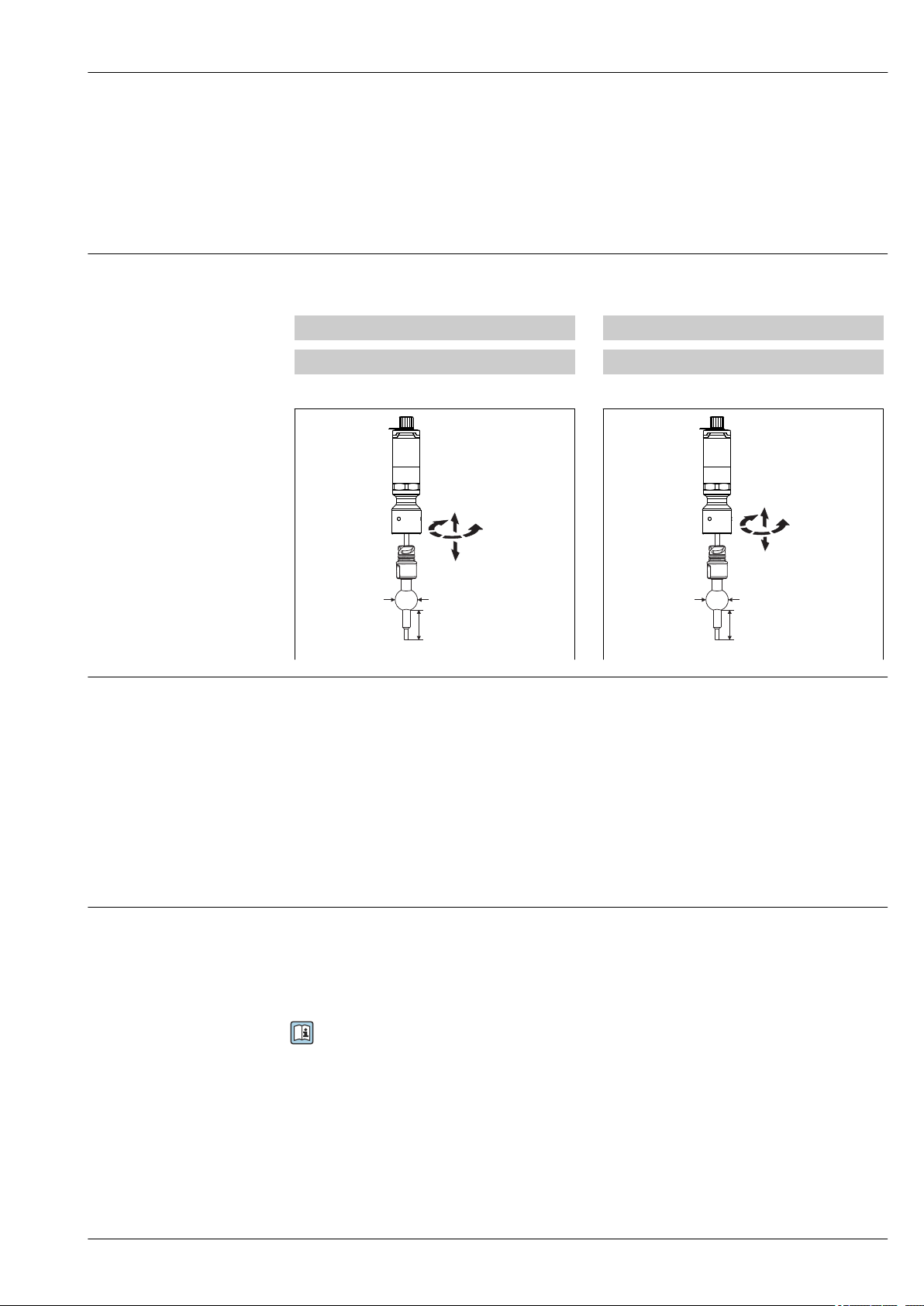
Differentiating factors when selecting a suitable thermometer
TM371 TM372
Metric version, all dimensions given in mm Imperial version, all dimensions given in inches
↓ ↓
Measuring principle Resistance thermometer (RTD)
These resistance thermometers use a Pt100 temperature sensor according to IEC 60751. The
temperature sensor is a temperature-sensitive platinum resistor with a resistance of 100 Ω at
0 °C (32 °F) and a temperature coefficient α = 0.003851 °C-1.
Thin film platinum resistance thermometers (TF): A ultrapure platinum layer, about 1 µm thick,
is applied by vapor deposition in a vacuum on a ceramic substrate and then structured
photolithographically. The platinum conductor paths formed in this way create the measuring
resistance. Additional covering and passivation layers are applied and reliably protect the thin
platinum layer from contamination and oxidation, even at high temperatures.
The primary advantages of thin film temperature sensors are their small sizes and good vibration
resistance.
A0031087
A0031088
Measuring system
Endress+Hauser offers a complete portfolio of optimized components for the temperature measuring
point – everything you need for the seamless integration of the measuring point into the overall
facility. This includes:
• Power supply unit/barrier
• Display units
• Overvoltage protection
For more information, see the brochure 'System Products and Data Managers - Solutions for the
loop' (FA00016K/EN)
Endress+Hauser 3
Page 4
iTHERM TrustSens TM371, TM372
2 3
1
4 5
U
1
2
3
4
5
6
A0031089
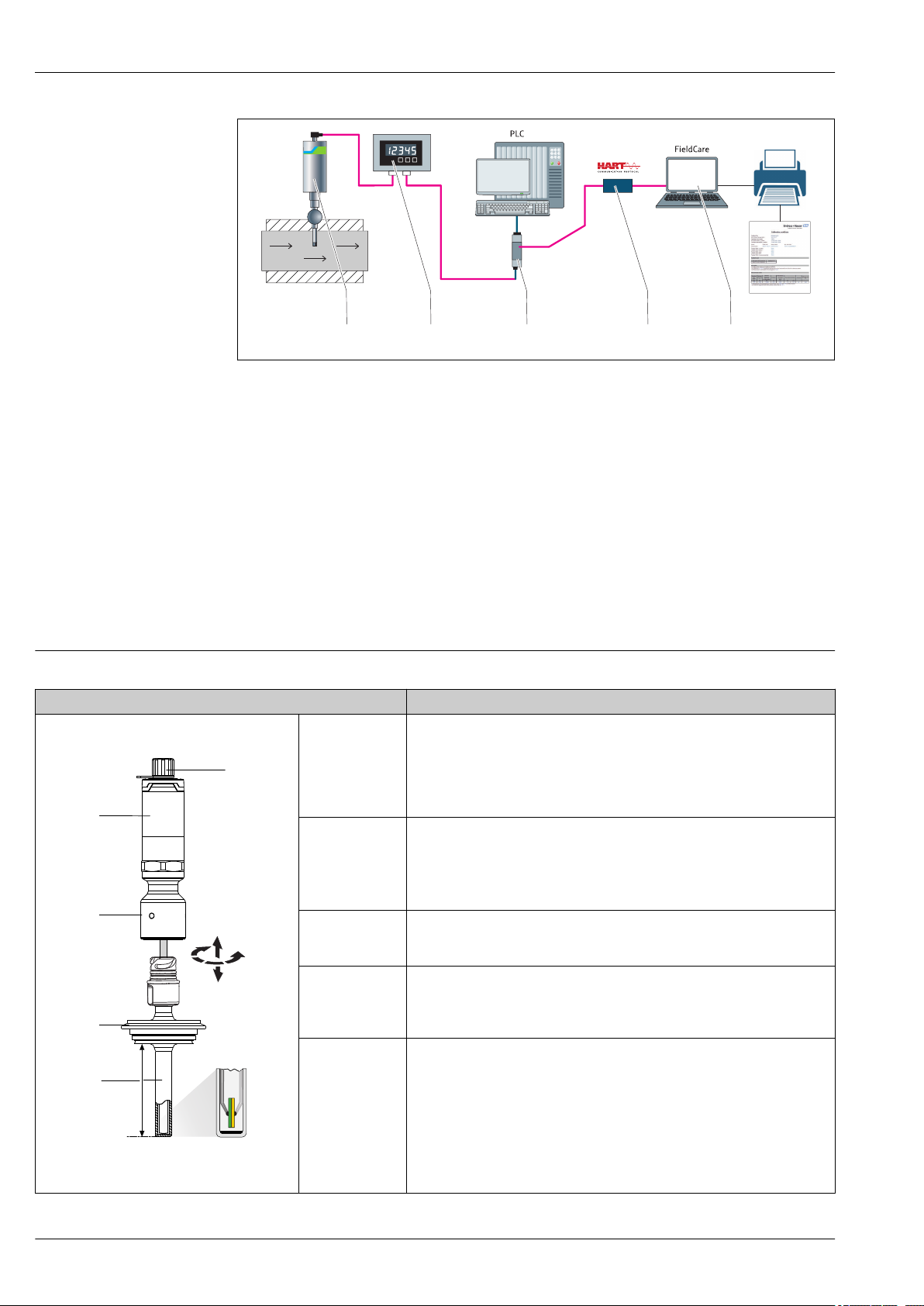
1 Example of application, measuring point layout with additional Endress+Hauser components
1
Installed iTHERM compact thermometer with HART® communication protocol
2 RIA15 loop powered process display - It is integrated in the current loop and displays the measuring signal or
HART® process variables in digital form. The process display unit does not require an external power supply.
It is powered directly from the current loop. More information on this can be found in the Technical
Information, see "Documentation", → 42.
3 Active barrier RN221N - The RN221N (24 V DC, 30 mA) active barrier has a galvanically isolated output for
supplying voltage to loop-powered transmitters. The universal power supply works with an input supply
voltage of 20 to 250 V DC/AC, 50/60 Hz, which means that it can be used in all international power grids.
More information on this can be found in the Technical Information, see "Documentation", → 42.
4 Commubox FXA195 for intrinsically safe HART® communication with FieldCare via the USB interface.
5 FieldCare is a FDT-based plant asset management tool from Endress+Hauser, more details see section
'accessories'. The acquired self-calibration data is stored in the device (1) and can be read using FieldCare.
This also enables an auditable calibration certificate to be created and printed.
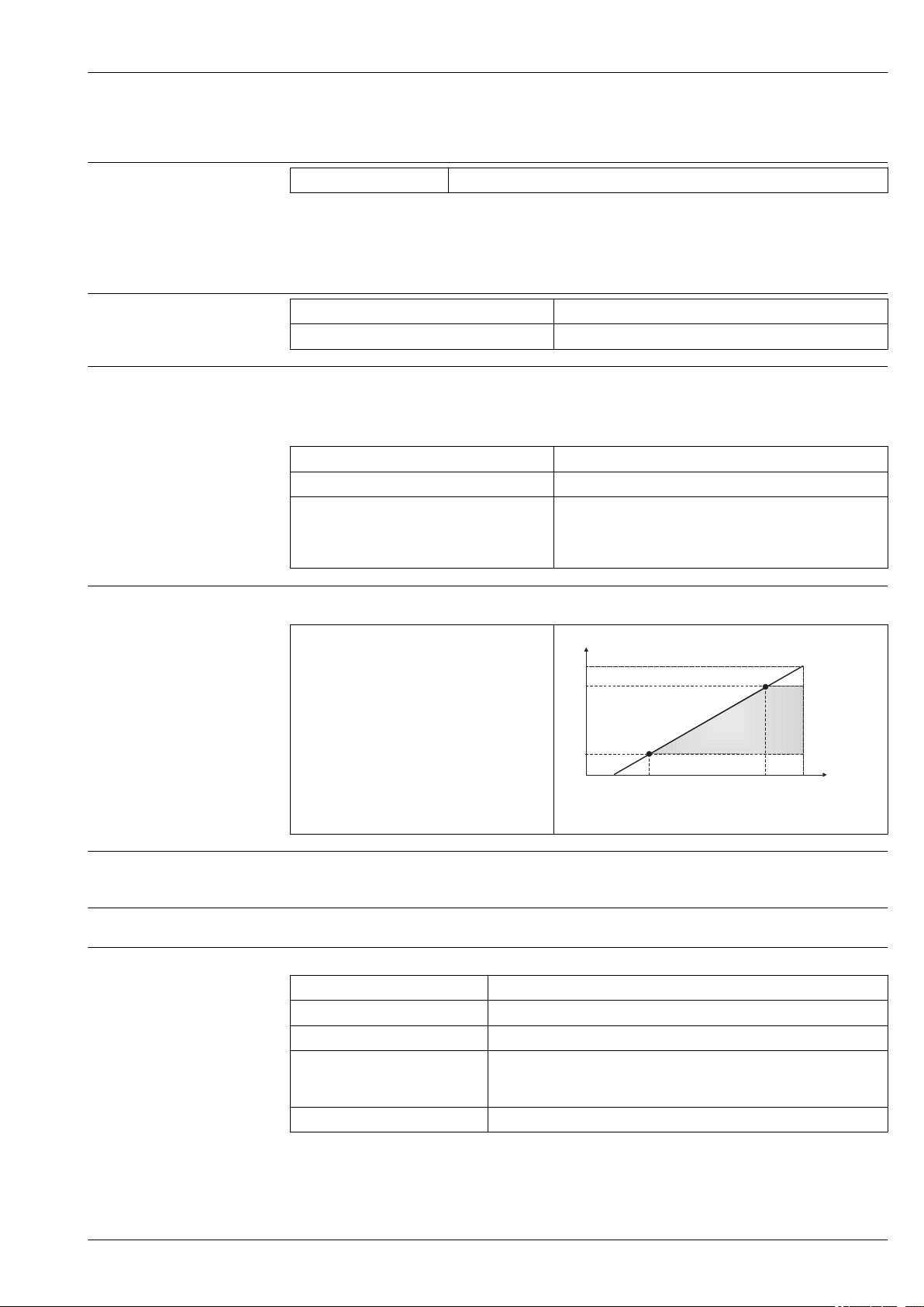
Equipment architecture
Design Options
1: Wiring,
electrical
connection,
output signal
2: Transmitter
housing
3: Extension neck • Welded-in-place or removable
4: Process
connection
→ 25
5: Protection tube • Versions with and without protection tube (insert in direct contact with
6: Insert Sensor model: thin-film Pt100 sensor (TF) with iTHERM TrustSens technology.
A0031106
Your benefits:
• Optimum protection even with high-pressure cleaning: As standard
IP67/68, optional IP69K protection
• M12, 4pin connector: cost and time savings as well as incorrect wiring
avoided
• Compact built-in transmitter (4 to 20 mA, HART®)
• Optional with iTHERM QuickNeck bayonet joint
Your benefits:
• iTHERM QuickNeck: tool-free removal of the compact thermometer
• IP69K protection: safety under extreme process conditions
More than 50 different versions.
process).
• Various diameters
• Various tip shapes (straight or reduced)
Your benefits:
• Risk and cost reduction thanks to Heartbeat technology
• Fully automated, traceable, inline self-calibration
• Automatized documentation, memory for the last 350 calibration
points
• Printable calibration certificate - audit proof
• No risk of unconformity or undetected failures
• International certifications and approvals
4 Endress+Hauser
Page 5
iTHERM TrustSens TM371, TM372
Ub
30 V
780
530
250
12 V
0
24.2 V
17.75 V
Supply voltage (V DC)
Load (Ω)
Input
Measuring range
Output signal
Failure information
Load
Pt100 thin-film (TF) –40 to +160 °C (–40 to +320 °F)
Output
Analog output 4 to 20 mA
Digital output HART® protocol (revision 7)
Failure information as per NAMUR NE43:
Failure information is created if the measuring information is missing or not valid. A complete list of
all the errors occurring in the measuring system is created.
Underranging Linear decrease from 4.0 to 3.8 mA
Overranging Linear increase from 20.0 to 20.5 mA
Failure, e.g. sensor breakage, sensor shortcircuit
Maximum possible HART® communication resistance
≤ 3.6 mA ("low") or ≥ 21 mA ("high"), can be selected
The "high" alarm setting can be set between 21.5 mA and
23 mA, thus providing the flexibility needed to meet the
requirements of various control systems.
Linearization/transmission behavior
Filter
Protocol-specific data
R
b max.
output)
= (U
- 12 V) / 0.023 A (current
b max.
Temperature-linear
1st order digital filter: 0 to 120 s, factory setting: 0 s (PV)
HART
Manufacturer ID 17 (0x11)
Device type ID 0x11CF
HART revision 7
Device description files (DTM, DD) Information and files at:
• www.endress.com/downloads
• www.fieldcommgroup.org
HART load Min. 250 Ω
A0032387-EN
Endress+Hauser 5
Page 6
iTHERM TrustSens TM371, TM372
HART device variables Measured value for PV (primary value)
Temperature
Measured values for SV, TV, QV (secondary, tertiary and quaternary
variable)
• SV: Device temperature
• TV: Calibration counter
• QV: Calibration deviation
Supported functions • Additional transmitter status
• NE107 diagnostics
Startup behavior / wireless HART data
Supply voltage
Current consumption
Minimum start-up voltage 12 V
Start-up current 3.58 mA
Start-up time < 7 s, until the first valid measured value signal is present at the current
Minimum operating voltage 12 V
Multidrop current 4 mA
Lead time 0 s
DC
output
DC
Wiring
According to the 3-A Standard electrical connecting cables must be smooth, corrosion-resistant
and easy to clean.
Ub = 12 to 30 V
The device may only be powered by a power supply unit with a limited energy electric circuit in
accordance with UL/EN/IEC 61010-1 chapter 9.4 or Class 2 according to UL 1310, "SELV or
Class 2 cir-cuit".
• I = 3.58 to 23 mA
• Minimum current consumption: I = 3.58 mA, multi-drop mode I =4 mA
• Maximum current consumption: I ≤ 23 mA
DC
Electrical connection
To prevent any kind of damage from the device electronics, leave the pins 2 and 4 unconnected.
They are reserved for the connection of the configuration cable.
Do not tighten the M12 plug too much, in order to prevent damage to the device. Maximum
torque: 0.4 Nm (M12 knurl)
6 Endress+Hauser
Page 7
iTHERM TrustSens TM371, TM372
M12x1
1
12...30 VDC
(4...20 mA)
3
0 V
(4...20 mA)
4
2
A
B
1 (BN) +
2 (WH)
3 (BU) -
4 (BK)
1
43
2
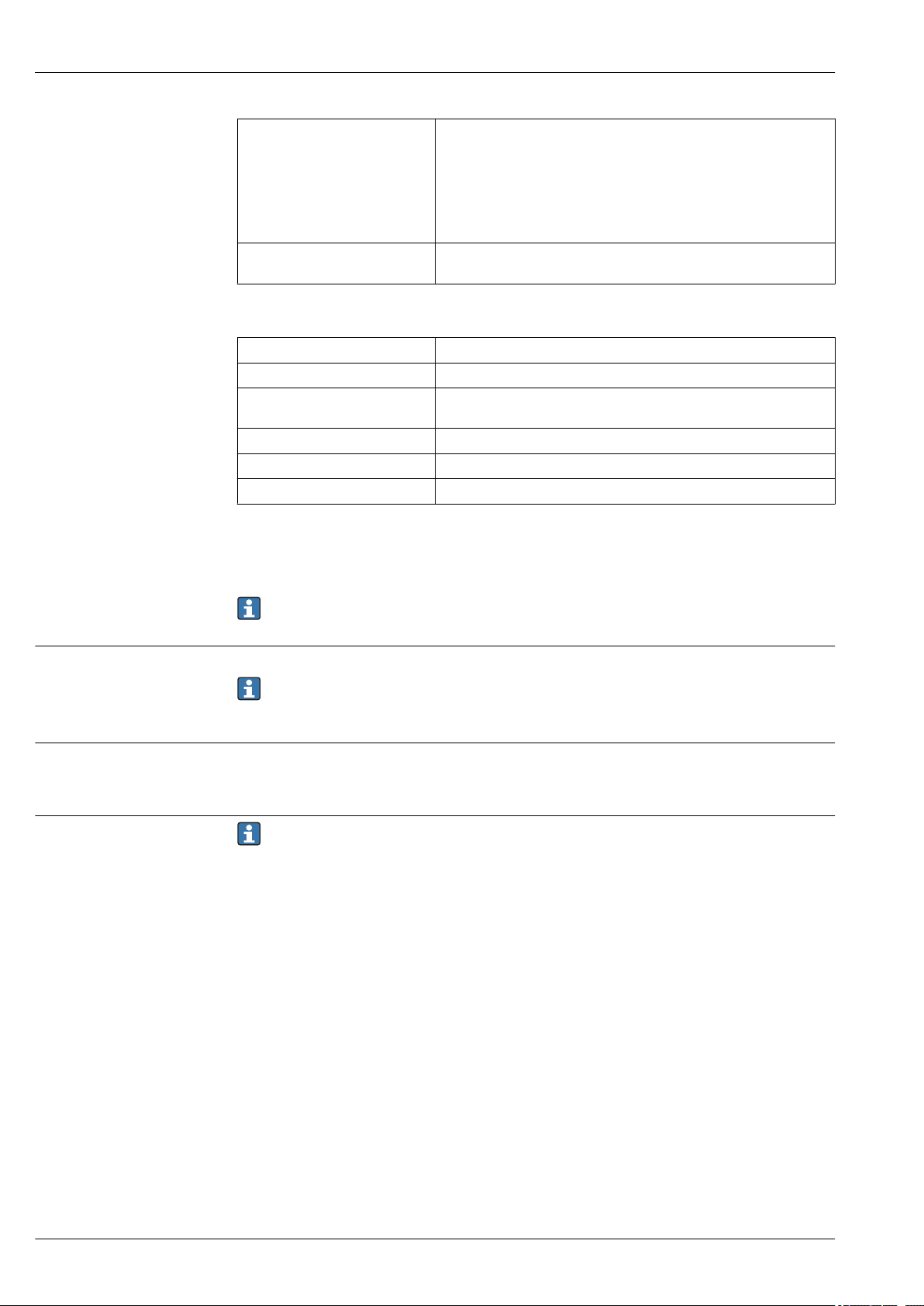
2 Pin assignment of the device connecting socket
1 Power supply 12 to 30 VDC; current output 4 to 20 mA
2 Reserved for configuration cable
3 Power supply 0 VDC; current output 4 to 20 mA
4 Reserved for configuration cable
Device plug connection
A0030963
Overvoltage protection
Reference operating conditions
Internal calibration point
A0030965
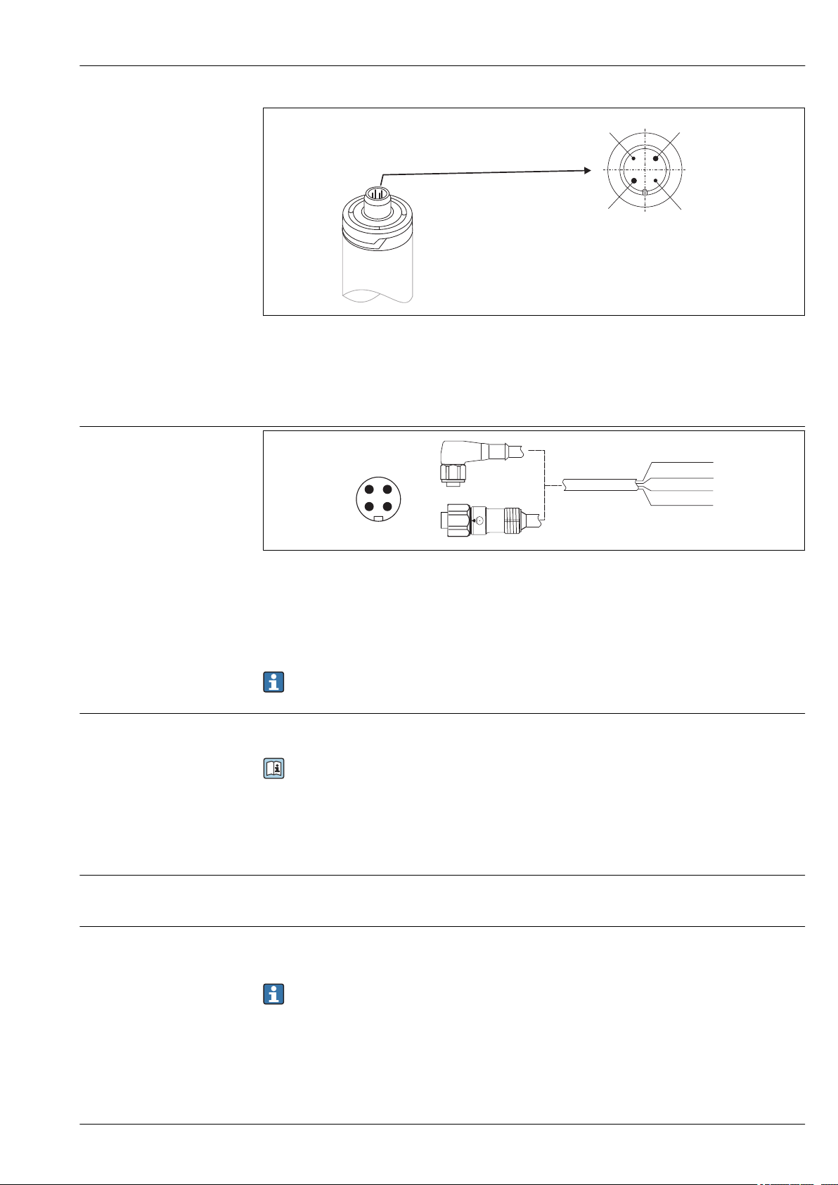
3 Pin assignment of the plug connector
1 Power supply +, wire color brown = BN
2 Connection of PC configuration cable, wire color white = WH
3 Power supply -, wire color blue = BU
4 Connection of PC configuration cable, wire color black = BK
Appropriate cord sets with straight or angle plugs are available as accessory.
To protect against overvoltage in the power supply and signal/communication cables for the
thermometer electronics, Endress+Hauser offers the HAW562 surge arrester for DIN rail mounting.
For more information see the Technical Information 'HAW562 Surge arrester' TI01012K
Performance characteristics
• Ambient temperature: 25 °C ± 5 °C (77 °F ± 9 °F)
• Supply voltage: 24 V
• 118 °C (244.4 °F) +1.2 K / –1.7 K
• Lowest possible calibration point = 116.3 °C (241.3 °F)
• Highest possible calibration point = 119.2 °C (246.6 °F)
The individual calibration point of each TrustSens device is indicated in the ex-works calibration
certificate enclosed with the shipment.
DC
Endress+Hauser 7
Page 8
iTHERM TrustSens TM371, TM372
Measurement uncertainty
Long-term drift
The given uncertainty values include non-linearity and non-repeatability and correspond to 2σ (95%
confidence level according to the Gaussian distribution curve).
Uncertainty of self-calibration of digital output (HART® value) at the
calibration point.
Uncertainty of the
temperature sensor inclusive
digital output (HART® value)
at reference conditions in
delivery state.
Each iTHERM TrustSens
is calibrated and
matched by default
before shipment to
guarantee the given
accuracy.
Uncertainty of D/A converter (analog output current) 0.03 % of the measurement
Pt100 sensing element < 1000 ppm/1000 h
A/D converter (digital output - HART®) < 500 ppm/1000 h
D/A converter (analog output - current) < 100 ppm/1000 h
1) This would be detected by the self-calibration
Process temperature:
+20 to +135 °C (+68 to +275 °F)
+135 to +160 °C (+275 to +320 °F)
0 to +20 °C (+32 to +68 °F)
–20 to 0 °C (–4 to +32 °F)
–40 to –20 °C (–40 to –4 °F)
< 0.35 °C (0.63 °F)
< 0.22 °C (0.4 °F)
< 0.38 °C (0.68 °F)
< 0.27 °C (0.49 °F)
< 0.46 °C (0.83 °F)
< 0.8 °C (1.44 °F)
range
1)
1)
Influence of ambient temperature
Influence of supply voltage
Long-term drift decreases at an exponential rate over time. So it may not be extrapolated in a
linear way for time spans longer than the above given values.
A/D converter (digital output - HART®) at typical
operating conditions
A/D converter (digital output - HART®) at maximum
operating conditions
D/A converter (analog output - current) ≤ 30 ppm/°C (2σ), related to the deviation from the
< 0.05 K (0.09 °F)
< 0.15 K (0.27 °F)
reference temperature
Typical operating conditions
• Ambient temperature: 0 to +40 °C (+32 to +104 °F)
• Process temperature: 0 to +140 °C (+32 to +284 °F)
• Power supply: 18 to 24 V
DC
According to IEC 61298-2:
A/D converter (digital output - HART®) at typical
operating conditions
D/A converter (analog output - current) < 10 ppm/V
1) Related to the deviation from the reference supply voltage
< 15 ppm/V
1)
1)
Sample calculation with Pt100, measuring range +20 to +135 °C (+68 to +275 °F), ambient
temperature +25 °C (+77 °F), supply voltage 24 V:
Measured error digital 0.220 °C (0.396 °F)
Measured error D/A = 0.03 % x 150 °C (302 °F) 0.045 °C (0.081 °F)
Measured error digital value (HART): 0.220 °C (0.396 °F)
Measured error analog value (current output): √(Measured error digital² +
Measured error D/A²)
0.225 °C (0.405 °F)
8 Endress+Hauser
Page 9
iTHERM TrustSens TM371, TM372
Sample calculation with Pt100, measuring range +20 to +135 °C (+68 to +275 °F), ambient
temperature +35 °C (+95 °F), supply voltage 30 V:
Measured error digital 0.220 °C (0.396 °F)
Measured error D/A = 0.03 % x 150 °C (302 °F) 0.045 °C (0.081 °F)
Influence of ambient temperature (digital) 0.050 °C (0.090 °F)
Influence of ambient temperature (D/A) = (35 °C - 25 °C) x (30 ppm/°C x 150 °C) 0.045 °C (0.081 °F)
Influence of supply voltage (digital) = (30 V - 24 V) x 15 ppm/V x 150 °C 0.014 °C (0.025 °F)
Influence of supply voltage (D/A) = (30 V - 24 V) x 10 ppm/V x 150 °C 0.009 °C (0.016 °F)
Response time
Measured error digital value (HART):
√(Measured error digital² + Influence of ambient temperature (digital)² + Influence
of supply voltage (digital)²
Measured error analog value (current output):
√(Measured error digital² + Measured error D/A² + Influence of ambient
temperature (digital)² + Influence of ambient temperature (D/A)² + Influence of
supply voltage (digital)² + Influence of supply voltage (D/A)²
Tests in water at 0.4 m/s (1.3 ft/s), according to IEC 60751; 10 K temperature step change. t63 / t
0.226 °C (0.407 °F)
0.235 °C (0.423 °F)
are defined as the time that passes until the instrument output reaches 63% / 90% of the new value.
Response time with heat transfer paste
Protection tube Shape of tip Insert t
6 mm (0.24 in) Reduced 4.3 mm (0.17 in) x 20 mm (0.79 in) 3 mm (0.12 in) 2.9 s 5.4 s
9 mm (0.35 in)
12.7 mm (¹⁄₂ in)
1) Between the insert and the protection tube.
Reduced 5.3 mm (0.21 in) x 20 mm (0.79 in) 3 mm (0.12 in) 2.9 s 5.4 s
Reduced 5.3 mm (0.21 in) x 20 mm (0.79 in) 3 mm (0.12 in) 2.9 s 5.4 s
Reduced 8 mm (0.31 in) x 32 mm (1.26 in) 6 mm (0.24 in) 10.9 s 24.2 s
1)
63
Straight 6 mm (0.24 in) 9.1 s 17.9 s
Straight 6 mm (0.24 in) 10.9 s 24.2 s
90
t
90
Response time without heat transfer paste
Protection tube Shape of tip Insert t
Without
protection tube
6 mm (0.24 in) Reduced 4.3 mm (0.17 in) x 20 mm (0.79 in) 3 mm (0.12 in) 7.4 s 17.3 s
9 mm (0.35 in)
12.7 mm (¹⁄₂ in)
Calibration
Reduced 5.3 mm (0.21 in) x 20 mm (0.79 in) 3 mm (0.12 in) 7.4 s 17.3 s
Reduced 5.3 mm (0.21 in) x 20 mm (0.79 in) 3 mm (0.12 in) 7.4 s 17.3 s
Reduced 8 mm (0.31 in) x 32 mm (1.26 in) 6 mm (0.24 in) 30.7 s 74.5 s
Calibration of thermometers
- 6 mm (0.24 in) 5.3 s 10.4 s
Straight 6 mm (0.24 in) 24.4 s 54.1 s
Straight 6 mm (0.24 in) 30.7 s 74.5 s
63
Calibration involves comparing the measured values of a device under test (DUT) with those of a
more precise calibration standard using a defined and reproducible measurement method. The aim is
to determine the deviation of the DUT's measured values from the true value of the measured
variable. Two different methods are used for thermometers:
• Calibration at fixed-point temperatures, e.g. at the freezing point of water at 0 °C,
• Comparison calibration against a precise reference thermometer.
The thermometer to be calibrated must display the fixed point temperature or the temperature of
the reference thermometer as accurately as possible. Temperature-controlled calibration baths or
special calibration furnaces with homogeneous distribution of temperature are typically used for
t
90
Endress+Hauser 9
Page 10
iTHERM TrustSens TM371, TM372
thermometer calibrations. The DUT and the reference thermometer are placed closely together into
the bath or furnace at a sufficient depth.
The measurement uncertainty can increase due to heat conduction errors and short immersion
lengths. The existing measurement uncertainty is listed on the individual calibration certificate.
For accredited calibrations according to IEC/ISO 17025, the measurement uncertainty must not be
twice as high as the accredited measurement uncertainty of the laboratory. If the limit value is
exceeded, only a factory calibration can be carried out.
For manual calibration in calibration baths the maximum immersion length of the device
ranges from the sensor tip to the lower part of the electronic housing. Do not immerse the
housing into the calibration bath!
A0032391
Self-calibration
The self-calibration procedure uses the Curie temperature (Tc) of a reference material as a built-in
temperature reference. A self-calibration is performed automatically, when the process temperature
(Tp) falls below the nominal Curie Temperature (Tc) of the device. At the Curie temperature, a phase
change of the reference material takes place, which is associated with a change in its electrical
properties. The electronics automatically detects this change and simultaneously calculates the
deviation of the measured Pt100-temperature to the known, physically fixed Curie temperature. The
TrustSens thermometer is calibrated. A green flashing LED light indicates the ongoing selfcalibration process. Subsequently the thermometer electronics stores the results of this calibration.
The calibration data can be read via an asset management software like FieldCare or DeviceCare. A
self-calibration certificate can be created automatically. This inline self calibration allows a
continuous and repeated monitoring of changes to the Pt100 sensor and to the electronics’
characteristics. As the inline calibration is being performed under real ambient or process conditions
(e.g. heating of electronics), the result is closer to reality than a sensor calibration under laboratory
conditions.
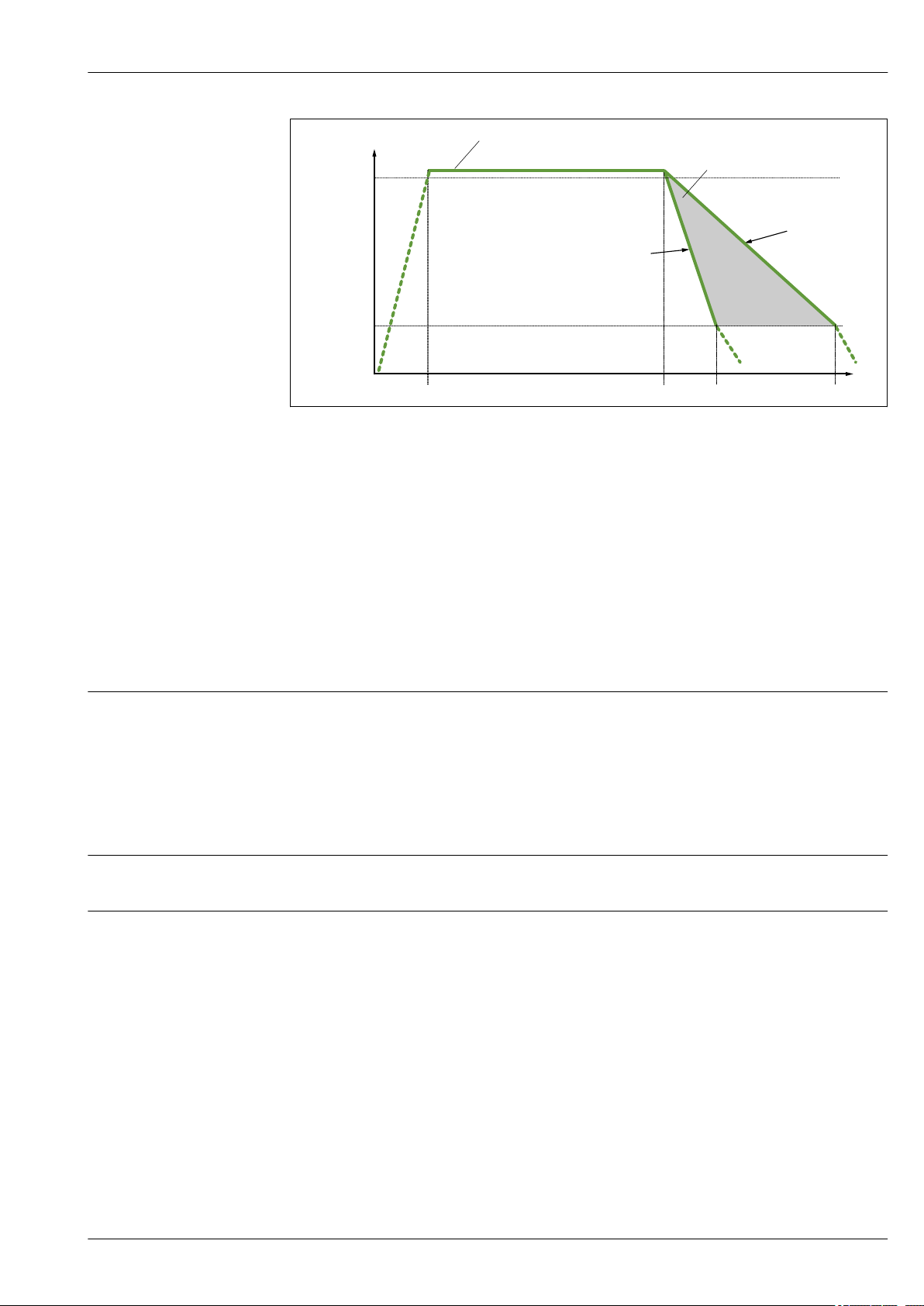
Process criteria for self-calibration
To ensure a valid self-calibration within the given measurement accuracy, the process temperature
characteristics needs to fulfil the criteria, which are checked by the device automatically. Based on
this, the device is ready to perform a self-calibration under the following conditions:
– Process temperature > calibration temperature +3 °C (5.4 °F) for 25 s before cooling down; t1 - t2.
– Cooling rate: 0.5 to 16.5 K/min (0.9 to 29.7 °F/min), while the process temperature crosses the
Curie temperature; t2 - t3 + 10 s.
The process temperature ideally declines continuously below 116 °C (240.8 °F). A valid selfcalibration process is done when the green LED flashes with a frequency 5 Hz for 5 s.
10 Endress+Hauser
Page 11
iTHERM TrustSens TM371, TM372
T / °C (°F)
t
123 °C
(253.4 °F)
> 25 s
< 116 °C (240.8 °F)
-16.5 K/min
(-29.7 °F/min)
t1
t2
1
t3
t3
116 °C
(240.8 °F)
-0.5 K/min
(-0.9 °F/min)
2
4 Needed process temperature profile for self-calibration
1 Process temperature 123 °C (253.4 °F)
2 Allowed self-calibration range
A0032839
Insulation resistance
Orientation
Installation instructions
Calibration monitoring
Available in conjunction with Advanced Data Manager Memograph M (RSG45). → 42
Application package:
• Up to 20 devices can be monitored via the HART interface
• Self-calibration data displayed on screen or via the Web server
• Generation of a calibration history
• Creation of a calibration protocol as an RTF file directly at the RSG45
• Evaluation, analysis and further processing of the calibration data using "Field Data Manager"
(FDM) analysis software
Insulation resistance ≥ 100 MΩ at ambient temperature.
Insulation resistance between the terminals and the outer jacket is measured with a minimum
voltage of 100 V DC.
Installation
No restrictions. However, self-draining in the process must be guaranteed. If there is an opening to
detect leaks at the process connection, this opening must be at the lowest possible point.
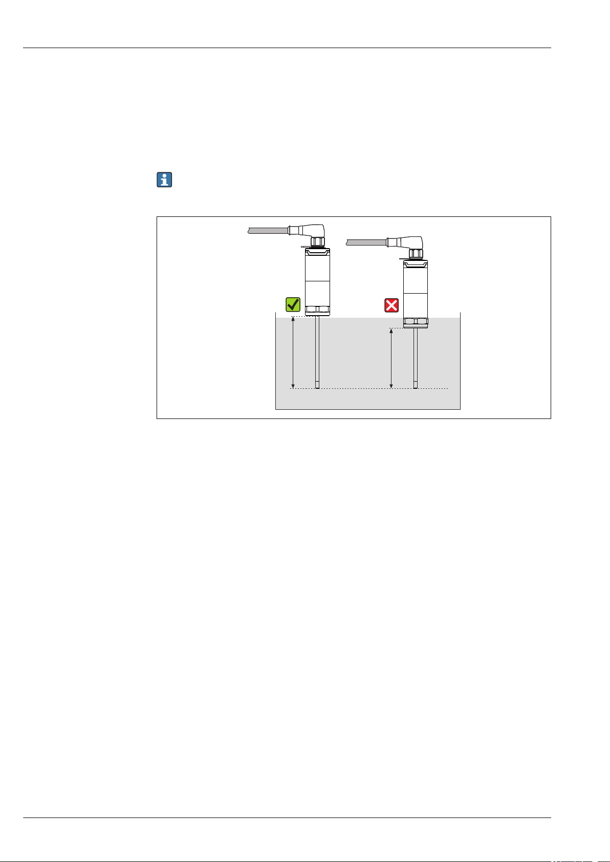
The immersion length of the thermometer can influence the accuracy. If the immersion length is too
small then errors in the measurement are caused by heat conduction via the process connection. If
installing into a pipe then the immersion length should ideally be half of the pipe diameter.
Installation possibilities: Pipes, tanks or other plant components
Endress+Hauser 11
Page 12
iTHERM TrustSens TM371, TM372
U
≥ 3°
≥ 3°
1
2
3
4
1
2
5 Installation examples
1, 2 Perpendicular to flow direction, installed at a min. angle of 3° to ensure self-draining
3 On elbows
4 Inclined installation in pipes with a small nominal diameter
U Immersion length
A0031007
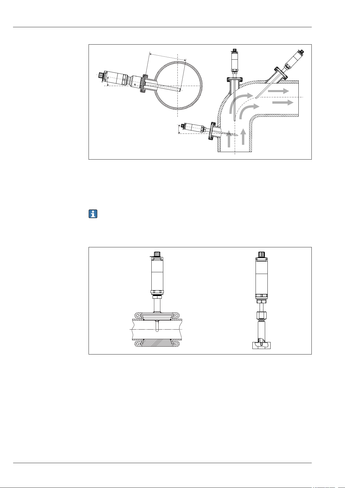
In the case of pipes with a small nominal diameter, it is advisable for the tip of the thermometer
to project well into the process so that it extends past the pipe axis. Installation at an angle (4)
could be another solution. When determining the immersion length or installation depth all the
parameters of the thermometer and of the medium to be measured must be taken into account
(e.g. flow velocity, process pressure).
6 Process connections for thermometer installation in pipes with small nominal diameters
1
Varivent® process connection type N for DN40
2 Corner-piece or T-piece (illustrated) for weld-in as per DIN 11865 / ASME BPE 2012
A0031022
12 Endress+Hauser
Page 13

iTHERM TrustSens TM371, TM372
1 2
3
4
R0.4 R0.4
Sensor with
milk pipe
connection
Sensor with Varivent
connection
Shaped
gasket
Companion
connection
O-ring
Groove
slip-on nut
Centering ring
Sealing
Companion
connection
Companion
connection
Gasket
(O-ring)
Welding boss
Leak detection hole
Vessel wall
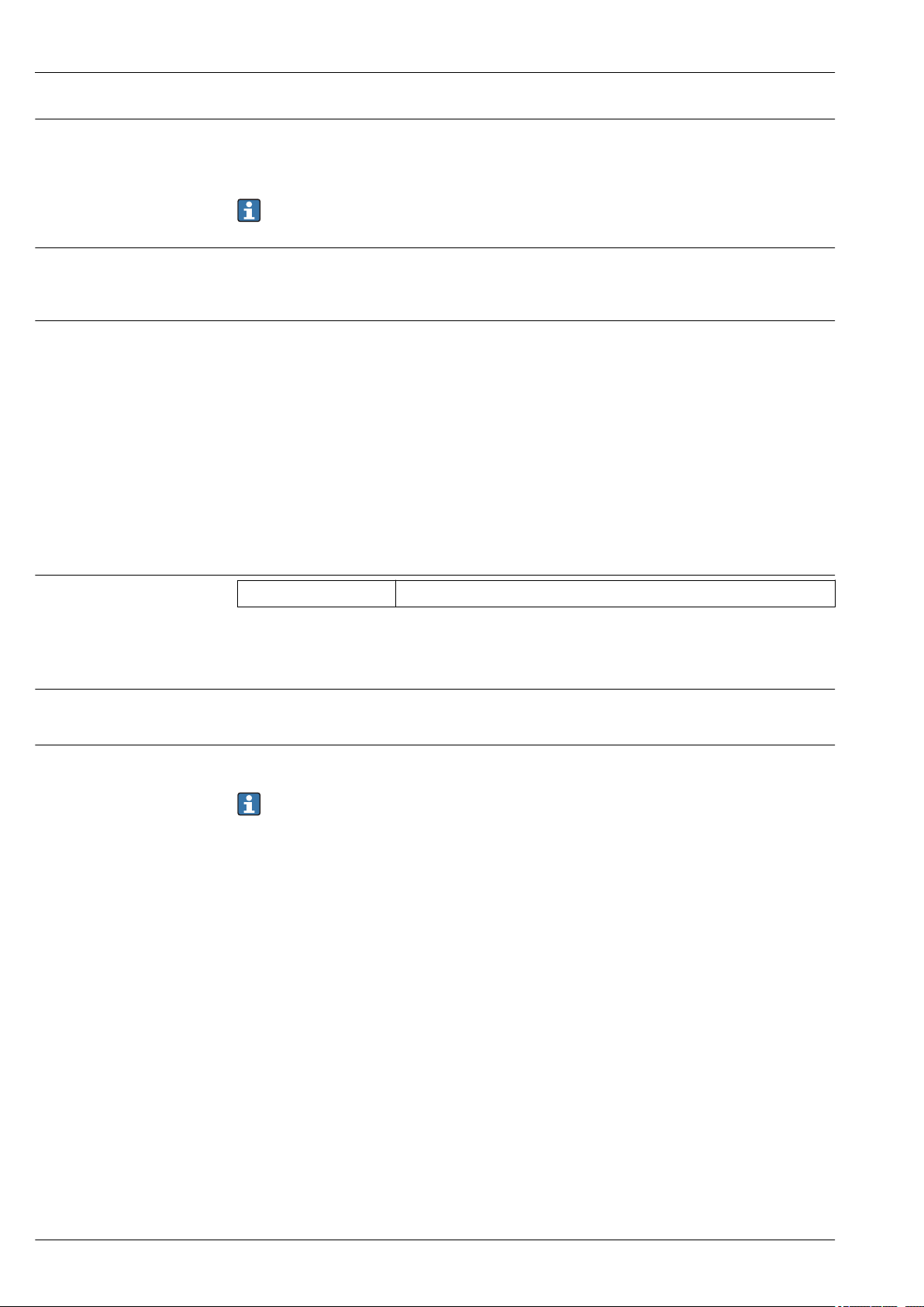
7 Detailed installation instructions for hygiene-compliant installation
1 Sanitary connection according to DIN 11851, only in connection with EHEDG-certified and self-centering
2
3 Clamp according to ISO 2852
4 Liquiphant-M G1" process connection, horizontal installation
A0011758-EN
sealing ring
Varivent® process connection for VARINLINE® housing
The counterpieces for the process connections and the seals or sealing rings are not included in
the scope of supply for the thermometer. Liquiphant M weld-in adapters with associated seal
kits are available as accessories.
Procedure in case of seal failure indicated by leak detection port:
• Disassembling of the thermometer, validated cleaning procedure of thread and and sealing
ring groove
• Replacement of the seal or sealing ring
• CIP after re-assembly
In the case of weld-in connections, exercise the necessary degree of care when performing the
welding work on the process side:
• Suitable welding material
• Flush-welded or with welding radius > 3.2 mm (0.13 in)
• No pits, folds, crevices or cracks
• Polished surface, Ra ≤ 0.76 µm (30 µin)
As a general rule, the thermometers should be installed in such a way that does not impact
their ability to be cleaned (the requirements of the 3-A Sanitary Standard must be observed).
The Varivent® and Liquiphant-M weld-in adapter and Ingold (+ weld-in adapter) connections
enable flush-mounted installation.
Environment
Ambient temperature range
Storage temperature range
Climate class
Endress+Hauser 13
Ambient temperature Ta–40 to +60 °C (–40 to +140 °F)
Maximum electronics
temperature T
–40 to +85 °C (–40 to +185 °F)
T = –40 to +85 °C (–40 to +185 °F)
As per IEC 60654-1, Class Dx
Page 14
iTHERM TrustSens TM371, TM372
Degree of protection
Shock and vibration resistance
Electromagnetic compatibility (EMC)
• IP54 for the version without protection tube provided for installation in an existing protection tube
• IP67/68 for housing with LED status indication
• IP69K for housing without LED status indication and only if appropriate cord-set with M12x1
coupling is connected. → 40
The specified rating IP67/68 or IP69K for the compact thermometer is only assured when an
approved M12 connector with a suitable IP rating is installed according to its manual.
Endress+Hauser temperature sensors meet the requirements of IEC 60751 which specify shock and
vibration resistance of 3g in the range from 10 to 500 Hz. This also applies for the quick-fastening
iTHERM QuickNeck.
EMC to all relevant requirements of the IEC/EN 61326 - series and NAMUR Recommendation EMC
(NE21). For details, refer to the Declaration of Conformity. All tests were passed both with and
without ongoing HART® communication.
All EMC measurements were performed with a turn down (TD) = 5:1. Maximum fluctuations during
EMC- tests: < 1% of measuring span.
Interference immunity to IEC/EN 61326 - series, requirements for industrial areas.
Interference emission to IEC/EN 61326 - series, electrical equipment Class B.
Process
Process temperature range
Thermal shock
Process pressure range
T
P
Reference sensor defective if temperature range of –45 to +200 °C (–49 to +392 °F) is exceeded.
Temperature measurement continues, but selfcalibration is out of function.
Thermal shock resistance in CIP/SIP process with a temperature increase and decrease from
+5 to +130 °C (+41 to +266 °F) within 2 seconds.
The maximum static process pressure is limited by the process connection, see respective section.
→ 25
It is possible to check the mechanical loading capacity as a function of the installation and
process conditions online in the TW Sizing Module for protection tubes in the Endress+Hauser
Applicator software. This is valid for DIN thermowell calculations. See 'Accessories' section.
Example of the permitted flow velocity depending on the immersion length and process
medium
The highest flow velocity tolerated by the thermometer diminishes with increasing immersion length
exposed to the stream of the fluid. In addition it is dependent on the diameter of the thermometer
tip, on the kind of process medium, on the process temperature and on the process pressure. The
following figures exemplify the maximum permitted flow velocities in water at a process pressure of
40 bar (580 PSI) and superheated steam at a process pressure of 6 bar (87 PSI).
–40 to +160 °C (–40 to +320 °F)
14 Endress+Hauser
Page 15

iTHERM TrustSens TM371, TM372
L (mm)
A
10
20
30
40
50
60
70
80
90
100
200
300 400 500
v (m/s)
B
0
4 8 10 16 20
L (in)
0
30
65
100
130
160
200
230
260
290
v (ft/s)
600
0
2 6 12 14 18 22 24
8 Permitted flow velocities, protection tube diameter 9 mm (0.35 in)
A Medium water at T = 50 °C (122 °F)
B Medium superheated steam at T = 160 °C (320 °F)
L Immersion length exposed to flow
v Flow velocity
Medium - state of
Gaseous or liquid (also with high viscosity, e.g. yogurt).
aggregation
Mechanical construction
Design, dimensions
Endress+Hauser 15
All dimensions in mm (in). The design of the thermometer depends on the protection tube version
used:
• Thermometer without a protection tube
• Diameter 6 mm (0.24 in)
• Diameter 9 mm (0.35 in)
• Diameter 12.7 mm (¹⁄₂ in)
• T-piece and corner-piece protection tube version as per DIN 11865 / ASME BPE 2012 for weld-in
Various dimensions, such as the immersion length U for example, are variable values and are
therefore indicated as items in the following dimensional drawings.
Variable dimensions:
Item Description
E Extension neck length, variable depending on the configuration or predefined for the version with
iTHERM QuickNeck
L Protection tube length (U+T)
B Protection tube bottom thickness: predefined, depends on protection tube version (see also the
individual table data)
T Length of protection tube shaft: variable or predefined, depends on protection tube version (see
also the individual table data)
A0032462
Page 16

iTHERM TrustSens TM371, TM372
U
"31.5
(1.24)
71 (2.8)
U
E = 45
(1.77)
"31.5
(1.24)
"31.5
(1.24)
121 (4.76)
U
15 (0.6)
M24
x1.5
117 (4.61)
U
12 (0.47)
"31.5
(1.24)
G3/8"
U
"31.5
(1.24)
131 (5.16)
27 (1.06)
1 2 3 5
6
" ID
" ID " ID
" ID " ID
"31.5
(1.24)
121 (4.76)
" ID
"9
(0.35)
G¼“
U
E = 70 (2.56)
7
4
"31.5
(1.24)
121 (4.76)
" ID
"9
(0.35)
U
E
G3/8”
Item Description
U Immersion length: variable, depending on the configuration
⌀ID Insert diameter 6 mm (0.24 in) or 3 mm (0.12 in)
Without protection tube
For installation with compression fitting TK40 as process connection and the insert in direct contact with the process or in an existing
protection tube.
1 Thermometer without extension neck, for mounting with adjustable compression fitting TK40, spherically and cylindrically, only ⌀ID = 6 mm
2 Thermometer with extension neck, for mounting with compression fitting TK40 in fix position, only ⌀ID = 6 mm
3 Thermometer with compression fitting TK40 fixed by extension neck, connection thread M24x1.5, ⌀ID = 6 mm
4 Thermometer with neck tube TE411, G3/8" thread adapter nut
5 Thermometer with M24x1.5 female thread for protection tube connection, e.g. TT411, ⌀ID = 3 mm or 6 mm
6 Thermometer with G3/8" female thread for protection tube connection, e.g. TT411, ⌀ID = 3 mm or 6 mm
7 Thermometer with iTHERM QuickNeck top part for protection tube with QuickNeck connection, ⌀ID = 3 mm or 6 mm
Item Description
U
(protection
tube)
T
(protection
tube)
E Length of the extension neck at point of installation (provided one is available)
B
(protection
tube)
Immersion length of the protection tube available at point of installation
Shaft length of protection tube available at point of installation
Base thickness of protection tube
Pay attention to the following equations when calculating the immersion length U for immersion into a protection tube TT411 already
available:
Version 5 U = U
Version 3, 4, 6 and 7 U = U
(protection tube)
(protection tube)
+ T
(protection tube)
+ T
(protection tube)
+ E + 3 mm - B
+ 3 mm - B
(protection tube)
(protection tube)
A0031214
16 Endress+Hauser
Page 17

iTHERM TrustSens TM371, TM372
!6
(0.24)
T
U
1
3
4
5
6
7
8
9
11
E = 34 (1.34)
117 (4.61)
131 (5.16)
15 (0.59)
E
T
U
2
B
10
With protection tube diameter 6 mm (0.24 in)
A0031254
1 Thermometer with extension neck and process connection as clamp version
2 Thermometer without extension neck and process connection as clamp version
3 Without process connection
4 Process connection version as spherical compression fitting TK40
5 Process connection version as metal sealing system M12x1
6 Process connection version as metal sealing system G½"
7 Process connection version as cylindrical weld-in adapter 12 x 40 mm
8 Process connection version as cylindrical weld-in adapter 30 x 40 mm
9 Process connection version as spherical-cylindrical weld-in adapter 30 x 40 mm
10 Process connection version as spherical weld-in adapter 25 x mm
11 Thermometer with quick-fastening iTHERM QuickNeck and process connection as sanitary connection (clamp
version)
G3/8" thread for protection tube connection
Item Version Length
Without extension neck -
Replaceable extenstion neck 9 mm (0.35 in) -
Extension neck E
Length of protection tube
1)
shaft T
iTHERM QuickNeck 34 mm (1.34 in)
Clamp DN12 according to ISO 2852 24 mm (0.94 in)
Clamp DN25/DN40 according to ISO 2852 21 mm (0.83 in)
Without process connection (only G3/8" thread), where
necessary with compression fitting TK40
Metal sealing system M12x1 46 mm (1.81 in)
Metal sealing system G½" 60 mm (2.36 in)
Cylindrical weld-in adapter 12 mm (0.47 in) 55 mm (2.17 in)
Cylindrical weld-in adapter 30 mm (1.18 in) 55 mm (2.17 in)
variable, depending
on the
configuration
12 mm (0.47 in)
Endress+Hauser 17
Page 18

iTHERM TrustSens TM371, TM372
Item Version Length
Spherical-cylindrical weld-in adapter 58 mm (2.28 in)
Spherical weld-in adapter 47 mm (1.85 in)
Tri-clamp (0.5"-0.75") 24 mm (0.94 in)
Microclamp (DN8-18) 23 mm (0.91 in)
Sanitary connection DN25/DN32/DN40 according to DIN
11851
Immersion length U Independent of the version
Bottom thickness B Reduced tip 4.3 mm (0.17 in) 2 mm (0.08 in)
1) Depends on the process connection
29 mm (1.14 in)
Variable, depending
on the
configuration
18 Endress+Hauser
Page 19

iTHERM TrustSens TM371, TM372
U
!9
(0.35)
T
U
T = 85
(3.35)
1
2
!9 (0.35)
B
B
!15 (0.6)
3 4 5 6 7 8
159 10 11 12 13
121 (4.76)
131 (5.16)
14
With protection tube diameter 9 mm (0.35 in)
1 Thermometer with extension neck, process connection as clamp version
2 Process connection version as cylindrical weld-in adapter 30 x 40 mm
3 Process connection version as spherical-cylindrical weld-in adapter 30 x 40 mm
4 Process connection version as spherical weld-in adapter 25 x mm
5 Process connection version as sanitary connection according to DIN 11851
6 Process connection version as aseptic pipe union according to DIN 11864-1 Form A
7 Process connection version as metal sealing system G½"
8 Process connection version as thread according to ISO 228 for Liquiphant weld-in adapter
9 Process connection version APV Inline
10
Process connection version Varivent
11 Process connection version Ingold connection
12 Process connection to SMS 1147
13 Process connection version Neumo Biocontrol
14 Process adapter D45
15 Thermometer with quick-fastening iTHERM QuickNeck and process connection, as clamp version for example
®
A0031343
Endress+Hauser 19
Page 20

iTHERM TrustSens TM371, TM372
Item Version Length
Extension neck E No separate extension neck available -
Without quick-fastening iTHERM QuickNeck independent of the process connection 85 mm (3.35 in)
Without quick-fastening iTHERM QuickNeck in combination with Ingold connection
25 mm (0.98 in) x 46 mm (1.81 in)
With quick-fastening iTHERM QuickNeck, depending on the process connection:
SMS 1147, DN25 40 mm (1.57 in)
SMS 1147, DN38 41 mm (1.61 in)
SMS 1147, DN51 42 mm (1.65 in)
Varivent®, type F, D = 50 mm (1.97 in)
Varivent®, type N, D = 68 mm (2.67 in)
Varivent®, type B, D = 31 mm (1.22 in) 56 mm (2.2 in)
Thread G1" according to ISO 228 for Liquiphant weld-in adapter 77 mm (3.03 in)
Spherical-cylindrical weld-in adapter 70 mm (2.76 in)
Cylindrical weld-in adapter 67 mm (2.64 in)
Aseptic pipe union according to DIN11864-A, DN25
Length of protection
tube shaft T
Immersion length U Independent of the version
Bottom thickness B
Aseptic pipe union according to DIN11864-A, DN40
Sanitary connection according to DIN 11851, DN32
Sanitary connection according to DIN 11851, DN40
Sanitary connection according to DIN 11851, DN50
Clamp according to ISO 2852, DN12
Clamp according to ISO 2852, DN25 37 mm (1.46 in)
Clamp according to ISO 2852, DN40
Clamp according to ISO 2852, DN70
Microclamp (DN18) 47 mm (1.85 in)
Tri-clamp (0.75") 46 mm (1.81 in)
Ingold connection 25 mm (0.98 in) x 30 mm (1.18 in) 78 mm (3.07 in)
Ingold connection 25 mm (0.98 in) x 46 mm (1.81 in) 94 mm (3.7 in)
Metal sealing system G½" 77 mm (3.03 in)
APV-Inline, DN50 51 mm (2.01 in)
Reduced tip 5.3 mm (0.21 in)x 20 mm (0.79 in)
Straight tip
100 mm (3.94 in)
52 mm (2.05 in)
45 mm (1.77 in)
47 mm (1.85 in)
48 mm (1.89 in)
39 mm (1.54 in)Clamp according to ISO 2852, DN63.5
Variable, depending
on the configuration
2 mm (0.08 in)
20 Endress+Hauser
Page 21

iTHERM TrustSens TM371, TM372
U
T
B
!12.7
(0.5)
B
T
U
43
1
5 6 7 8
E = 34 (1.34)
15 (0.59)
117 (4.61)
131 (5.16)
11 (0.43)
T
U
E
2
With protection tube diameter 12.7 mm (¹⁄₂ in)
A0031372
1 Thermometer with standard extension neck, thread and process connection as clamp version
2 Thermometer with extension neck and process connection as clamp version
3 Process connection version as cylindrical weld-in adapter 12.7 mm (½ in)
4 Process connection version as spherical weld-in adapter 25 mm (1 in)
5 Process connection version as sanitary connection according to DIN 11851
6 Thread according to ISO 228 for Liquiphant weld-in adapter
7
Process connection version Varivent
8 Thermometer with quick-fastening iTHERM QuickNeck and process connection, as clamp version for example
®
• G3/8" thread for protection tube connection
• Protection tube made from solid bar stock drilled for L ≤ 200 mm (7.87 in)
• Welded protection tube for L > 200 mm (7.87 in)
Item Version Length
Without extension neck -
9 mm (0.35 in) -
Extension neck E
Length of protection tube
shaft T
Immersion length U Independent of the process connection
Bottom thickness B
Replaceable extension neck
iTHERM QuickNeck 34 mm (1.34 in)
Weld-in adapter, cylindrical, 12.7 mm (¹⁄₂ in) 12 mm (0.47 in)
All other process connections 65 mm (2.56 in)
Reduced tip 5.3 mm (0.21 in)x 20 mm (0.79 in) 2 mm (0.079 in)
Reduced tip 8 mm (0.31 in)x 32 mm (1.26 in) 4 mm (0.16 in)
Straight tip 6 mm (0.24 in)
variable, depending on
the configuration
Variable, depending on
the configuration
Endress+Hauser 21
Page 22

With tee- or elbow piece protection tube version
1
2
3
4
117 (4.61)
82.7 (3.26)
E
15 (0.6)
131 (5.16)
11 (0.43)
0.7 (0.03)
E = 34 (1.34)
!4.5 (0.18)
11 (0.43)
G3/8" G3/8"
iTHERM TrustSens TM371, TM372
1 Thermometer with extension neck and tee-piece protection tube
2 Version with tee-piece protection tube
3 Version with elbow piece
4 Thermometer with quick-fastening iTHERM QuickNeck and elbow piece protection tube
Item Version Length
Without extension neck -
Replaceable extension neck 9 mm (0.35 in) -
Extension neck E
iTHERM QuickNeck 34 mm (1.34 in)
Bottom thickness B Independent of the version 0.7 mm (0.03 in)
Immersion length U Independent of the version 82.7 mm (3.26 in)
variable, depending
on the
configuration
• Pipe sizes according to DIN11865 series A (DIN), B (ISO) and C (ASME BPE)
• Nominal diameters > DN25, with 3-A symbol
• IP69K protection class
• Material 1.4435+316L, Delta ferrite content <0.5%
• Temperature measurement range: –60 to +200 °C (–76 to +392 °F)
• Pressure range: PN25 according to DIN11865
Due to the small immersion length U in pipes with a small nominal diamter, the use of iTHERM
QuickSens inserts is recommended.
A0031515
22 Endress+Hauser
Page 23

iTHERM TrustSens TM371, TM372
Possible combinations of the protection tube versions with the available process connections
and quick-fastening iTHERM QuickNeck
Process connection and size
Without process connection (for installation with
compression fitting)
Protection tube diameter
6 mm (0.24 in)
2)
9 mm (0.35 in) 12.7 mm (¹⁄₂ in)
- - -
iTHERM QuickNeck for 9 mm
2)
(0.35 in)
Process adapter D45 - - -
Weld-in adapter
Cylindrical 12.7 mm (0.5 in) - - -
Cylindrical 30 x 40 mm
-
Cylindrical 12 x 40 mm - - -
Spherical-cylindrical 30 x 40 mm -
Spherical 25 mm (0.98 in) -
Clamp according to ISO 2852
Microclamp/Tri-clamp DN18 (0.75 in)
-
DN12 - 21.3
DN25 -38 (1 - 1.5 in)
DN40 - 51 (2 in)
DN63.5 (2.5 in)
-
DN70 - 76.5 (3 in)
Sanitary connection according to DIN 11851
DN25
DN32, DN40
DN50 -
Aseptic pipe union according to DIN 11864-1 Form A
DN25, DN40 - -
Metal sealing system
M12x1
-
-
G½"
Thread according to ISO 228 for Liquiphant weld-in adapter
G¾" for FTL31/33/20
G¾" for FTL50 -
-
G1" for FTL50
APV Inline
DN50 - -
Varivent
®
Type B, 31 mm; Type F, 50 mm ; Type N, 68 mm -
Ingold connection
25 x 30 mm or 25 x 46 mm - -
SMS 1147
DN25, DN38, DN51 - -
1)
-
-
-
Endress+Hauser 23
Page 24

iTHERM TrustSens TM371, TM372
Process connection and size
6 mm (0.24 in)
Protection tube diameter
2)
9 mm (0.35 in) 12.7 mm (¹⁄₂ in)
iTHERM QuickNeck for 9 mm
2)
(0.35 in)
Neumo Biocontrol
D25 PN16, D50 PN16, D65 PN16 - - -
1) In the case of 6 mm (0.24 in) and 12.7 mm (½ in) diameters, the iTHERM QuickNeck is available for all process connection versions.
2) All versions available with iTHERM QuickNeck
Weight
Material
0.2 to 2.5 kg (0.44 to 5.5 lbs) for standard options.
The temperatures for continuous operation specified in the following table are only intended as
reference values for use of the various materials in air and without any significant compressive load.
The maximum operating temperatures can be reduced considerably in cases where abnormal
conditions such as high mechanical load occur or in aggressive media.
Recommended
Designation Short form
AISI 316L
(corresponds to
1.4404
X2CrNiMo17-13-2,
X2CrNiMo18-14-3
or 1.4435)
1.4435+316L, delta
ferrite < 1% or <
0.5%
With regard to analytical limits, the specifications of both materials (1.4435 and 316L)
are met simultaneously. In addition, the delta ferrite content of the wetted parts is
limited to <1% - including the welding seams (following Basel Standard II); or <0.5%
max. temperature
for continuous use
in air
650 °C (1 202 °F)
1)
Properties
• Austenitic, stainless steel
• High corrosion resistance in general
• Particularly high corrosion resistance in
chlorine-based and acidic, non-oxidizing
atmospheres through the addition of
molybdenum (e.g. phosphoric and
sulfuric acids, acetic and tartaric acids
with a low concentration)
• Increased resistance to intergranular
corrosion and pitting
1)
Surface roughness
1) Can be used to a limited extent up to 800 °C (1472 °F) for low compressive loads and in non-corrosive
media. Contact your Endress+Hauser sales team for further information.
Values for wetted surfaces:
1)
Mechanically polished surface Ra ≤ 0.76 µm (30 µin)
Mechanically polished surface
2)
Ra ≤ 0.38 µm (15 µin)
Mechanically polished surface and electropolished Ra ≤ 0.38 µm (15 µin)+ electropolished
1) Exception: internal welding seams of the tee- and elbow pieces
2) Not compliant with ASME BPE
24 Endress+Hauser
Page 25

iTHERM TrustSens TM371, TM372
!d
U
U
U
h
!d
!d
h
!d
h
!d
1 2
3
4
5
U
T
U
T
T
T
h
A
B
U
!d
!D
1
2
R0.4
R0.4
!i
!a
Protection tube Process connections
All dimensions in mm (in).
For welding in
Type Version Dimensions Technical properties
Weld-in adapter
1: Cylindrical
2: Cylindrical
3: Cylindrical d x h = 30 mm (1.18 in) x 40 mm (1.57 in)
4: Spherical-
cylindrical
5: Spherical d = 25 mm (0.98 in)
1)
d = 12.7 mm (¹⁄₂ in), U = immersion length
from lower edge of thread,
T = 12 mm (0.47 in)
2)
d x h = 12 mm (0.47 in) x 40 mm (1.57 in),
T = 55 mm (2.17 in)
d x h = 30 mm (1.18 in) x 40 mm (1.57 in)
h = 24 mm (0.94 in)
• P
depends on the weld-in
max.
process
• 3-A marked and EHEDG
certification
• ASME BPE compliance
A0009569
1) For protection tube 12.7 mm (½ in)
2) For protection tube 6 mm (0.24 in)
Releasable process connection
Sanitary connection according to DIN 11851
1 Centering ring
2 Sealing ring
1)
Version
DN25
DN32 50 mm
Type Technical properties
• 3-A marked and EHEDG
certification (only with
EHEDG-certified and selfcentering sealing ring).
• ASME BPE compliance
A0009561
Dimensions
D A B i a
44 mm
(1.73 in)
(1.97 in)
30 mm
(1.18 in)
36 mm
(1.42 in)
10 mm
(0.39 in)
10 mm
(0.39 in)
26 mm
(1.02 in)
32 mm
(1.26 in)
29 mm
(1.14 in)
35 mm
(1.38 in)
40 bar (580 psi)
40 bar (580 psi)
P
max.
Endress+Hauser 25
Page 26

DN40 56 mm
!D
h
U
!d
!i
!a
!D
U
!d
!a
!d
U
!D
R0.8
R0.5
0.8 ± 0.1
2.16 ± 0.1
R1.2
R0.8
0.4
1.6
A
A: Microclamp
A: Tri-clamp
DN50 68 mm
1) Pipes in accordance with DIN 11850
iTHERM TrustSens TM371, TM372
Type Technical properties
(2.2 in)
(2.68 in)
42 mm
(1.65 in)
54 mm
(2.13 in)
10 mm
(0.39 in)
11 mm
(0.43 in)
38 mm
(1.5 in)
50 mm
(1.97 in)
41 mm
(1.61 in)
53 mm
(2.1 in)
40 bar (580 psi)
25 bar (363 psi)
Type Version
Aseptic pipe union according to DIN
11864-1, Form A
Type
Clamp according to ISO 2852
A0009562
DN8-18 (0.5"-0.75")
Tri-clamp DN8-18
Dimensions
d D i a h
DN25 26 mm
(1.02 in)
DN40 38 mm
(1.5 in)
42.9 mm
(1.7 in)
54.9 mm
(2.16 in)
26 mm
(1.02 in)
38 mm
(1.5 in)
29 mm
(1.14 in)
41 mm
(1.61 in)
9 mm
(0.35 in)
10 mm
(0.39 in)
Version Dimensions
1)
d:
Microclamp
2)
3)
D a
-
25 mm (0.98 in)
(0.5"-0.75")
DN12-21.3 34 mm (1.34 in)
DN25-38 (1"-1.5") 50.5 mm (1.99 in)
-
16 to 25.3 mm
(0.63 to 0.99 in)
29 to 42.4 mm
(1.14 to 1.67 in)
DN40-51 (2") 64 mm (2.52 in) 44.8 to 55.8 mm
(1.76 to 2.2 in)
DN63.5 (2.5") 77.5 mm (3.05 in) 68.9 to 75.8 mm
(2.71 to 2.98 in)
DN70-76.5 (3") 91 mm (3.58 in) > 75.8 mm (2.98 in) • P
Technical properties
• P
= 40 bar (580 psi)
max.
• 3-A marked and EHEDG
certification
• ASME BPE compliance
Technical properties
• P
= 16 bar (232 psi),
max.
depends on clamp ring and
suitable seal
• 3-A marked
• P
= 16 bar (232 psi),
max.
depends on clamp ring and
suitable seal
• 3-A marked and EHEDG
certification (combined with
Hyjoin PEEK/stainless steel
seal or Dupont de Nemours
Kalrez/stainless steel seal)
• ASME BPE compliance
= 16 bar (232 psi),
max.
depends on clamp ring and
suitable seal
• 3-A marked
• ASME BPE compliance
4)
A Different seal geometries for
1) Pipes in accordance with ISO 2037 and BS 4825 Part 1
2) Microclamp (not in ISO 2852); no standard pipes
3) DN8 (0.5") only possible with protection tube diameter = 6 mm (0.24 in)
4) Not for DN12-21.3
Microclamp and Tri-clamp
A0009566
26 Endress+Hauser
Page 27

iTHERM TrustSens TM371, TM372
U
14
(0.55)
22 (0.87)
M12
1.5x
!10
(0.4)
8 (0.3)
!6
(¼)
G3/8"
T = 46 (1.81)
20°
U
14
(0.55)
37 (1.46)
G½”
!18
(0.71)
8 (0.31)
!6 (¼)
G3/8"
T = 60 (2.36)
22.5°
U
14
(0.55)
37 (1.46)
G½”
"18 (0.71)
8 (0.31)
"9 (0.35)
T
45°
U
35 (1.38)
20
(0.79)
5 (0.20)
!45 (1.77)
!50 (1.97)
U
L1
1
G
A
Metal sealing system
M12x1.5
Type Version Technical properties
G½"
P
= 16 bar (232 psi)
Protection tube diameter
6 mm (0.24 in)
max.
Maximum torque =
10 Nm (7.38 lbf ft)
A0009574
-
Type Version Technical properties
Process adapter
D45 • 3-A marked
A0020856
Protection tube diameter
9 mm (0.35 in)
A0009571
P
= 16 bar (232 psi)
max.
Maximum torque =
10 Nm (7.38 lbf ft)
• EHEDG certification
A0034881
Dimensions
Type Version G
Thread according to ISO 228 (for weld-in
adapter)
Endress+Hauser 27
A0009572
G¾" for
FTL31/33/20
adapter
G¾" for FTL50
adapter
G1" for FTL50-
adapter
L1 thread
length
16 mm
(0.63 in)
18.6 mm
(0.73 in)
A 1 (SW/AF)
25.5 mm (1 in) 32
29.5 mm
(1.16 in)
41
Technical properties
• P
= 25 bar (362 psi) at
max.
max. 150 °C (302 °F)
• P
= 40 bar (580 psi) at
max.
max. 100 °C (212 °F)
• 3-A marked and EHEDG
certification
• ASME BPE compliance
Page 28

iTHERM TrustSens TM371, TM372
h
!d
M
!A
!B
U
U
!D
!B
!A
h
U
!D
!i
!a
Type Version
APV Inline
A0018435
Type Version
®
Varivent
d A B M h
DN50
69 mm
(2.72 in)
D A B h P
Type B 31 mm
(1.22 in)
Type F 50 mm
(1.97 in)
Type N 68 mm
(2.67 in)
Dimensions
Technical properties
• P
= 25 bar (362 psi)
99.5 mm
(3.92 in)
82 mm
(3.23 in)
2xM8
19 mm
(0.75 in)
max.
• 3-A marked and EHEDG
certification
• ASME BPE compliance
Dimensions Technical properties
max.
105 mm
(4.13 in)
145 mm
(5.71 in)
165 mm
(6.5 in)
- 22 mm
135 mm
(5.31 in)
155 mm
(6.1 in)
(0.87 in)
24 mm
(0.95 in)
24.5 mm
(0.96 in)
10 bar
(145 psi)
• 3-A marked and EHEDG
certification
• ASME BPE compliance
A0021307
The VARINLINE® housing connection flange is suitable for weld-in into the conical or torispherical head in tanks or containers with a small
diameter (≤ 1.6 m (5.25 ft)) and up to a wall thickness of 8 mm (0.31 in).
Type Technical properties
Varivent® for VARINLINE® housing for installation in pipes
• 3-A marked and EHEDG
certification
• ASME BPE compliance
A0009564
Dimensions
Version
D i a
P
max.
DN40: 38 mm (1.5 in) DN40: 41 mm (1.61 in)
DN50: 50 mm (1.97 in) DN50: 53 mm (2.1 in)
DN40 to DN65:
16 bar (232 psi)
DN65: 66 mm (2.6 in) DN65: 70 mm (2.76 in)
Type N, according to DIN
11866, series A
28 Endress+Hauser
68 mm (2.67 in)
DN80: 81 mm (3.2 in) DN80: 85 mm (3.35 in)
DN100: 100 mm (3.94 in) DN100: 104 mm (4.1 in)
DN125: 125 mm (4.92 in) DN125: 129 mm (5.08 in)
DN150: 150 mm (5.9 in) DN150: 154 mm (6.06 in)
DN80 to DN150:
10 bar (145 psi)
Page 29

iTHERM TrustSens TM371, TM372
!D
!3.1
(0.12)
!4.5 (0.18)
G3/8”
L
!18 (0.71)
s
83 (3.26)
0.7 (0.03)
Version
Type N, according to EN
ISO 1127, series B
Type N, according to DIN
11866, series C
Type N, according to DIN
11866, series C
D i a
68 mm (2.67 in)
68 mm (2.67 in)
68 mm (2.67 in)
Advanced tee-piece (no welds, no dead legs)
Type Version
Tee-piece for weld-in as per DIN 11865
(part A, B and C)
A0035898
Dimensions
38.4 mm (1.51 in) 42.4 mm (1.67 in)
44.3 mm (1.75 in) 48.3 mm (1.9 in)
56.3 mm (2.22 in) 60.3 mm (2.37 in)
72.1 mm (2.84 in) 76.1 mm (3 in)
82.9 mm (3.26 in) 42.4 mm (3.5 in)
108.3 mm (4.26 in) 114.3 mm (4.5 in)
OD 1½": 34.9 mm (1.37 in) OD 1½": 38.1 mm (1.5 in)
OD 2": 47.2 mm (1.86 in) OD 2": 50.8 mm (2 in)
OD 2½": 60.2 mm (2.37 in) OD 2½": 63.5 mm (2.5 in)
OD 3": 73 mm (2.87 in) OD 3": 76.2 mm (3 in)
OD 4": 97.6 mm (3.84 in) OD 4": 101.6 mm (4 in)
D L s
Part A DN10 PN25 13 mm
(0.51 in)
DN15 PN25 19 mm
(0.75 in)
DN20 PN25 23 mm
(0.91 in)
DN25 PN25 29 mm
(1.14 in)
DN32 PN25 32 mm
(1.26 in)
Part B DN13,5 PN25 13.5 mm
(0.53 in)
DN17,2 PN25 17.2 mm
(0.68 in)
DN21,3 PN25 21.3 mm
(0.84 in)
DN26,9 PN25 26.9 mm
(1.06 in)
DN33,7 PN25 33.7 mm
(1.33 in)
Part
2)
C
DN12,7 PN25
(½")
DN19,05
PN25 (¾")
DN25,4 PN25
(1")
DN38,1 PN25
(1½")
12.7 mm
(0.5 in)
19.05 mm
(0.75 in)
25.4 mm
(1 in)
38.1 mm
(1.5 in)
Dimensions in mm (in)
48 mm
(1.89 in)
1)
1.5 mm
(0.06 in)
1.6 mm
(0.063 in)
2 mm
(0.08 in)
1.65 mm
(0.065 in)
P
max.
42.4 mm (1.67 in) to
60.3 mm (2.37 in):
16 bar (232 psi)
76.1 mm (3 in) to
114.3 mm (4.5 in):
10 bar (145 psi)
OD 1½" to OD 2½":
16 bar (232 psi)
OD 3" to OD 4": 10 bar (145 psi)
Technical properties
• P
= 25 bar (362 psi)
max.
• 3-A marked for > DN25
1) Wall thickness
2) Dimensions as per ASME BPE 2012
Endress+Hauser 29
Page 30

Advanced elbow piece (no welds, no dead legs)
!D
!3.1
(0.12)
83 (3.26)
0.7 (0.03)
!4.5
(0.18)
G3/8”
L1
L2
!D
U
x
4
(0.16)
h
!D
G1¼“
iTHERM TrustSens TM371, TM372
Type Version
Elbow piece for weld-in as per DIN 11865
(part A, B and C)
A0035899
D L1 L2 s
Part A DN10 PN25 13 mm
(0.51 in)
DN15 PN25 19 mm
(0.75 in)
DN20 PN25 23 mm
(0.91 in)
DN25 PN25 29 mm
(1.14 in)
DN32 PN25 35 mm
(1.38 in)
Part B DN13,5
PN25
DN17,2
PN25
DN21,3
PN25
DN26,9
PN25
DN33,7
PN25
Part C DN12,7
PN25 (½")
DN19,05
PN25 (¾")
DN25,4
PN25 (1")
DN38,1
PN25 (1½")
2)
13.5 mm
(0.53 in)
17.2 mm
(0.68 in)
21.3 mm
(0.84 in)
26.9 mm
(1.06 in)
33.7 mm
(1.33 in)
12.7 mm
(0.5 in)
19.05 mm
(0.75 in)
25.4 mm
(1 in)
38.1 mm
(1.5 in)
Dimensions
24 mm
(0.95 in)
25 mm
(0.98 in)
27 mm
(1.06 in)
30 mm
(1.18 in)
33 mm
(1.3 in)
32 mm
(1.26 in)
34 mm
(1.34 in)
36 mm
(1.41 in)
29 mm
(1.14 in)
32 mm
(1.26 in)
24 mm
(0.95 in)
25 mm
(0.98 in)
28 mm
(1.1 in)
35 mm
(1.38 in)
1)
1.5 mm
(0.06 in)
1.6 mm
(0.063 in)
2.0 mm
(0.08 in)
1.65 mm
(0.065 in)
Technical properties
• P
= 25 bar (362 psi)
max.
• 3-A marked for > DN25
1) Wall thickness
2) Dimensions as per ASME BPE 2012
Type Version, dimensions D x h Technical properties
Ingold connection
25 mm (0.98 in) x 30 mm (1.18 in)
x = 1.5 mm (0.06 in)
25 mm (0.98 in) x 46 mm (1.81 in)
x = 6 mm (0.24 in)
A0009573
P
= 25 bar (362 psi)
max.
A seal is included in the
delivery
Material V75SR: FDA
compliant, 3-A compliant, USP
Class VI compliant
30 Endress+Hauser
Page 31

iTHERM TrustSens TM371, TM372
U
1
2
3
h
!D
!A
U
h
!D
!A
M
!B
Type Version
SMS 1147 DN25 32 mm
DN38 48 mm
DN51 60 mm
A0009568
1 Thread adapter nut
2 Sealing ring
3 Counterpart connection
The counterpart connection must fit the sealing ring and fix it in place.
Type Version
Neumo Biocontrol
A0018497
D25
PN16
D50
PN16
D65
PN25
A B D d h
64 mm
(2.52 in)
90 mm
(3.54 in)
120 mm
(4.72 in)
Dimensions
D A h
35.5 mm
(1.26 in)
(1.89 in)
(2.36 in)
50 mm
(1.97 in)
70 mm
(2.76 in)
95 mm
(3.74 in)
(1.4 in)
55 mm
(2.17 in)
65 mm
(2.56 in)
Dimensions
30.4 mm
(1.2 in)
49.9 mm
(1.97 in)
67.9 mm
(2.67 in)
7 mm
(0.28 in)
9 mm
(0.35 in)
11 mm
(0.43 in)
7 mm (0.28 in)
8 mm (0.31 in)
9 mm (0.35 in)
20 mm
(0.79 in)
27 mm
(1.06 in)
Technical properties
P
= 6 bar (87 psi)
max.
Technical properties
• P
= 16 bar (232 psi)
max.
• 3-A marked
Endress+Hauser 31
Page 32

Compression fitting
!di
!D
!di
!D
h
h
!d
!d
!7 (0.28)
2 (0.08)
20 (0.8)
D2 = !5.3
(0.21)
!3.2
(0.13)
2 (0.08)
40 (1.6)
20
(0.8)
D2 = !6.6
(0.26)
!4.1
(0.16)
2 (0.08)
20 (0.8)
D2 = !5.3
(0.21)
!3.2
(0.13)
2 (0.08)
6 (0.24)
D2 = !8
(0.31)
4
(1.6)
20 (0.8)
D2 = !4.3
(0.17)
2 (0.08)
2 31
!D1
!D1
!!D1 =
D2
!D1
!D1
!D1
!3.3
(0.13)
!8 (0.31) /
1
!6.6 (0.26)
32 (1.26)
!6.4
(0.25)
!!D1 =
D2
iTHERM TrustSens TM371, TM372
Type
Version Dimensions
Spherical or cylindrical di D h
Compression fitting TK40 for weld-in
Spherical
Ferrule material PEEK or
316L
Thread G¼"
Cylindrical
Ferrule material Elastosil®
Thread G½"
A0017582
1) All the pressure specifications apply for cyclic temperature load
2) For insert or protection tube diameter Ød = 6 mm (0.236 in).
6.3 mm
(0.25 in)
6.2 mm
(0.24 in)
9.2 mm
(0.36 in)
Technical properties
• P
= 10 bar (145 psi),
max.
T
= +150 °C (+302 °F) for
max.
PEEK material, tightening
torque = 10 Nm
• P
= 50 bar (725 psi),
25 mm
(0.98 in)
2)
30 mm
(1.18 in)
33 mm
(1.3 in)
57 mm
(2.24 in)
max.
T
= +200 °C (+392 °F) for
max.
316L material, tightening
torque = 25 Nm
• PEEK compression fitting is
EHEDG tested and 3-A
marked
• P
= 10 bar (145 psi)
max.
• T
for Elastosil® ferrule =
max.
+150 °C (+302 °F),
tightening torque = 5 Nm
• Elastosil® compression
fitting is EHEDG tested
1)
Tip shape
The thermal response time, the reduction of the flow cross-section and the mechanical load that
occurs in the process are the criteria that matter when selecting the shape of the tip. Advantages of
using reduced or tapered thermometer tips:
• A smaller tip shape has less impact on the flow characteristics of the pipe carrying the medium.
• The flow characteristics are optimized, thereby increasing the stability of the thermowell.
• Endress+Hauser offers users a range of thermowell tips to meet every requirement:
– Reduced tip with 4.3 mm (0.17 in) and 5.3 mm (0.21 in): walls of lower thickness
significantly reduce the response times of the overall measuring point.
– Tapered tip with 6.6 mm (0.26 in) and reduced tip with 8 mm (0.31 in): walls of greater
thickness are particularly well suited to applications with a higher degree of mechanical load or
wear (e.g. pitting, abrasion etc.).
32 Endress+Hauser
9 Thermowell tips available (reduced, straight or tapered)
A0017174
Page 33

iTHERM TrustSens TM371, TM372
1
Item No. Thermowell (D1) Insert (ID)
1) The thermowell is made from barstock for L ≤ 200 mm (7.87 in). The tip is welded on for L > 200 mm
2) For L ≤ 200 mm (7.87 in) = internal diameter 8 mm (0.31 in). For L > 200 mm (7.87 in) = internal
1 6 mm (¹⁄₄ in) Reduced tip 3 mm (¹⁄₈ in)
2 9 mm (0.35 in)
3 12.7 mm (¹⁄₂ in)
(7.87 in).
diameter 6.6 mm (0.26 in)
• Reduced tip with 5.3 mm (0.21 in)
• Straight tip
• Tapered tip with 6.6 mm (0.26 in)
• Reduced tip with 5.3 mm (0.21 in)
1)
• Straight tip
• Reduced tip with 8 mm (0.31 in)
2)
• 3 mm (¹⁄₈ in)
• 6 mm (¹⁄₄ in)
• 3 mm (¹⁄₈ in)
• 3 mm (¹⁄₈ in)
• 6 mm (¹⁄₄ in)
• 6 mm (¹⁄₄ in)
It is possible to check the mechanical loading capacity as a function of the installation and
process conditions online in the TW Sizing Module for thermowells in the Endress+Hauser
Applicator software. See 'Accessories' section.
Operability
Operating concept
Local operation LED signals
The configuration of device-specific parameters is done via the HART protocol or CDI interface (=
Endress+Hauser Common Data Interface). There are specific configuration or operating programs
from different manufacturers available to the user for this purpose. Both the DD (Device Description)
as well as the DTM (Device Type Manager) files are being provided for the iTHERM TrustSens
thermometers.
Self-calibration
A self-calibration certificate similar to laboratory calibration can be created with a DTM and can be
printed on demand. The necessary measurement data is stored in the device and can be requested by
the DTM.
Position LEDs Function description
LED for device status
1
indication
LED green (gn)
is illuminated
LED green (gn) is flashing
LED red (rd) and green
(gn) are flashing
alternating
A0031589
LED red (rd) is flashing Presence of a diagnostic event: "Warning"
LED red (rd) is illuminated Presence of a diagnostic event: "Alarm"
Voltage supply is correct. The device is
operational and the set limit values are met.
With a frequency 1 Hz: self-calibration
currently being performed.
With a frequency 5 Hz for 5 s: self-calibration
finished and valid, all process criteria were
within specifications. Calibration data stored.
Self-calibration process finished but not valid,
violation of necessary process criteria.
Calibration data not stored.
Operating elements
To prevent manipulation, no operating elements are present directly on the device. The thermometer
is configured only by remote operation.
Remote operation
Configuration
Configuration kits, e. g. Commubox FXA195 or TXU10, for PC-programmable thermometer with
setup software and interface for PC with USB port.
Endress+Hauser 33
Page 34

iTHERM TrustSens TM371, TM372
HART® functions and device-specific parameters are configured by HART® communication or via the
interface of the device. There are special configuration tools like FieldCare or DeviceCare by Endress
+Hauser. For more information, contact your Endress+Hauser sales representative.
Operating tools
Operating tool Sources for obtaining the required device descriptions (DD) or device
type manager (DTM)
FieldCare
(Endress+Hauser)
DeviceCare
(Endress+Hauser)
FieldXpert SFX350, SFX370
(Endress+Hauser)
• www.endress.com → Download Area → Software
• DVD (contact Endress+Hauser)
www.endress.com → Download Area → Software
Use update function of handheld terminal
Certificates and approvals
CE mark
EAC mark
cCSAus
MTBF
Hygiene standard
Other standards and guidelines
The product meets the requirements of the harmonized European standards. As such, it complies
with the legal specifications of the EC directives. The manufacturer confirms successful testing of the
product by affixing to it the CE-mark.
The product meets the legal requirements of the EEU guidelines. The manufacturer confirms the
successful testing of the product by affixing the EAC mark.
The product complies with "CLASS 2252 05 - Process Control Equipment" and "CLASS 2252 85 Process Control Equipment - Certified to US Standards" requirements.
For the transmitter: 180 years - according to Siemens Standard SN29500
• EHEDG certification, type EL - CLASS I. Permitted process connections in accordance with EHEDG,
see 'Process connections' section → 25
• 3-A authorization no. 1144, 3-A sanitary standard 74-06. Permitted process connections in
accordance with 3-A, see also 'Process connections' section
• ASME BPE, certificate of conformity can be ordered for indicated options
• FDA-compliant
• All product contact surfaces are produced without materials used derived from bovine or other
animal sources (TSE Certificate of Suitability)
• IEC 60529: Degrees of protection provided by enclosures (IP code)
• IEC 61010-1: Safety requirements for electrical equipment for measurement, control and
laboratory use
• IEC 60751: Industrial platinum resistance thermometers
• DIN 43772: Protection tubes
Parts in contact with the medium
Parts of the thermometer in contact with the medium comply with the following European
regulations:
• (EC) No. 1935/2004, Article 3, paragraph 1, Articles 5 and 17 on materials and articles intended
to come into contact with food.
• (EC) No. 2023/2006 on good manufacturing practice for materials and articles intended to come
into contact with food.
• (EU) No. 10/2011 on plastic materials and articles intended to come into contact with food.
CRN approval
The CRN approval is only available for certain options of protection tubes. These will be marked and
shown during the configuration of this device.
34 Endress+Hauser
Page 35

iTHERM TrustSens TM371, TM372
Detailed ordering information is available from the following sources:
• In the download area on the Endress+Hauser website: www.endress.com → Select your country →
Downloads → Enter product code or device → Media type: Approvals & certificates → Select type of
approval → Start search
• From your nearest Endress+Hauser sales organization: www.addresses.endress.com
Surface purity
Material resistance
Material certification
Calibration
Protection tube testing and load capacity calculation
Cleaned from oil and grease for O2 applications, optional
Material resistance - including housing - to the following cleaning agents/disinfectants from the
company Ecolab: P3-topax 66, P3-topactive 200, P3-topactive 500 and P3-topactive OKTO as well as
demineralized water.
The material certificate 3.1 (according to standard EN 10204) can be requested separately. The
"short form" certificate includes a simplified declaration with no enclosures of documents related to
the materials used in the construction of the single sensor and guarantees the traceability of the
materials through the identification number of the thermometer. The data related to the origin of
the materials can subsequently be requested by the client if necessary.
The "Factory calibration" is carried out according to an internal procedure in a laboratory of Endress
+Hauser accredited by the European Accreditation Organization (EA) to ISO/IEC 17025. A
calibration which is performed according to EA guidelines (SIT/Accredia) or (DKD/DAkkS) may be
requested separately.
The analog current output of the device is calibrated.
• Protection tube pressure tests are carried out in accordance with the specifications in DIN 43772.
With regard to protection tubes with tapered or reduced tips that do not comply with this
standard, these are tested using the pressure of corresponding straight protection tubes. Tests
according to other specifications can be carried out on request.
• Load capacity calculation for the protection tube as per DIN43772
Heartbeat diagnostics
Ordering information
Detailed ordering information is available from the following sources:
• In the Product Configurator on the Endress+Hauser website: www.endress.com -> Click "Corporate"
-> Select your country -> Click "Products" -> Select the product using the filters and search field ->
Open product page -> The "Configure" button to the right of the product image opens the Product
Configurator.
• From your Endress+Hauser Sales Center: www.addresses.endress.com
Product Configurator - the tool for individual product configuration
• Up-to-the-minute configuration data
• Depending on the device: Direct input of measuring point-specific information such as
measuring range or operating language
• Automatic verification of exclusion criteria
• Automatic creation of the order code and its breakdown in PDF or Excel output format
• Ability to order directly in the Endress+Hauser Online Shop
Application packages
Available in all device versions.
Function
• Continuous self-monitoring of the device
• Diagnostic messages output to:
– the local display
– an asset management system (e.g. FieldCare/DeviceCare)
– an automation system (e.g. PLC)
Endress+Hauser 35
Page 36

iTHERM TrustSens TM371, TM372
Advantages
• Device condition information is available immediately and processed in time.
• The status signals are classified in accordance with VDI/VDE 2650 and NAMUR recommendation
NE 107 and contain information about the cause of the error and remedial action.
For detailed information on Heartbeat functions, see the Operating Instructions → 42
Heartbeat verification
Heartbeat Monitoring
Available in all device versions.
Device functionality checked on demand
• Verification of the correct functioning of the measuring device within specifications
• The verification result provides information about the condition of the device: "Passed" or "Failed"
• The results are documented in a verification report
• The automatically generated report supports the obligation to demonstrate compliance with
internal and external regulations, laws and standards
• Verification is possible without interrupting the process
Advantages
• No onsite presence is required to use the function
• The DTM
1)
triggers verification in the device and interprets the results. No specific knowledge is
required on the part of the user.
• The verification report can be used to prove quality measures to a third party.
• Heartbeat Verification can replace other maintenance tasks (e.g. periodic check) or extend the test
intervals.
For detailed information on Heartbeat functions, see the Operating Instructions → 42
Available in all device versions.
Function
Calibration information is logged in addition to the verification parameters. 350 calibration points
are saved in the device (FIFO memory).
Advantages
• Early detection of changes (trends) to ensure plant availability and product quality.
• Use of information for the proactive planning of measures (e.g. maintenance).
For detailed information on Heartbeat functions, see the Operating Instructions → 42
1) Device Type Manager: controls device operation via DeviceCare, FieldCare or a DTM-based process control system.
36 Endress+Hauser
Page 37

iTHERM TrustSens TM371, TM372
!30 (1.18)
16 (0.63)
34 (1.34)
15 (0.6)
G½”
M12x1.5
!7.6 (0.3)
!20 (0.8)
13 (0.51)
17 (0.67)
8 (0.31)
!18
(0.71)
G½”/
M12x1.5
37 (1.46)
AF22
G 1¼”
50 (1.97)
Accessories
Device-specific accessories
Device-specific accessories
Accessories Description
Welding boss with sealing taper (metal -
metal)
Welding boss for G½" and M12x1.5 thread
Metal-sealing; conical
Material of wetted parts: 316L/1.4435
Max. process pressure 16 bar (232 PSI)
Order number:
• 60021387 (G½")
• 71405560 (M12x1.5)
A0006621
A0018236
Dummy plug
A0009213-EN
Weld-in adapter for Ingold process
connections
Dummy plug for G½” or M12x1.5 conical metal-sealing welding boss
Material: SS 316L/1.4435
Order number:
• 60022519 (G½")
• 60021194 (M12x1.5)
Material of wetted parts: 316L/1.4435
Weight: 0.32 kg (0.7 lb)
Order number: 60017887
O-ring seal set
• Silicone O-ring in accordance with FDA CFR 21
• Maximum temperature: 230 °C (446 °F)
• Order number: 60018911
A0008956
Endress+Hauser 37
Page 38

iTHERM TrustSens TM371, TM372
ø
26 (1.0)
25 (1.0)
ø
29 (1.1)
30 (1.2)
G
ISO 228
¾"
ø32 (1.3)
ø
50 (2.0)
26 (1.0)
21 (0.8)
ø
32 (1.3)
G ¾
ISO 228
"
26 (1.0)
ø
55 (2.2)
21 (0.8)
ø
32 (1.3)
G ¾
ISO 228
"
ø50 (2.0)
ø53 (2.1)
47.8 (1.9)
24.6 (1.0)
30°
21 (0.8)
ø41 (1.6)
G 1"
ISO 228
Weld-in adapter for FTL31/33/20,
pipe-mounting
A0008265
1) A seal is included in the delivery.
Weld-in adapter for FTL31/33/20,
vessel-mounting
G¾", d=29 mm, without flange
Material: 316L
Roughness in μm (μin): 1.5 (59.1)
Order number: 52028295 (with inspection certificate EN10204-3.1
material)
Order number seal (5-pc. set): silicone O-ring 52021717
compliant
G¾", d=50 mm, with flange
Material: 316L
Roughness in μm (μin): 0.8 (31.5)
Order number: 52018765 (with inspection certificate EN10204-3.1
material)
Order number seal (5-pc. set): silicone O-ring 52021717
compliant
EHEDG tested and 3-A marked
1)
, FDA-
1)
, FDA-
A0008810
1) A seal is included in the delivery.
Weld-in adapter for FTL50
A0008274
1) A seal is included in the delivery.
Weld-in adapter for FTL50
G¾", d=55 mm, with flange
Material: 316L
Roughness in μm (μin): 0.8 (31.5)
Order number: 52001052 (without inspection certificate
EN10204-3.1 material)
Order number: 52011897 (with inspection certificate EN10204-3.1
material)
Order number seal (5-pc. set): silicone O-ring 52014473
compliant
Order number weld-in dummy: MVT2L0692
EHEDG tested and 3-A marked
G1", d=53 mm, without flange
Material: 316L
Roughness in μm (μin): 0.8 (31.5)
Order number: 71093129 (with inspection certificate EN10204-3.1
material)
Order number seal (5-pc. set): silicone O-ring 52014472
compliant
Order number weld-in dummy: MVT2L0691
1)
, FDA-
1)
, FDA-
38 Endress+Hauser
1) A seal is included in the delivery.
A0011927
Page 39

iTHERM TrustSens TM371, TM372
ø41 (1.6)
G 1"
ISO 228
ø60 (2.4)
29.6 (1.2)
24.6 (1.0)
26 (1.02)
5 (0.2)
ø65 (2.56)
!D
20 (0.79)
35 (1.38)
Weld-in adapter for FTL50
A0008267
1) A seal is included in the delivery.
Weld-in adapter for FTL50
G1", d=60 mm, with flange
Material: 316L
Roughness in μm (μin): 0.8 (31.5)
Order number: 52001051 (without inspection certificate
EN10204-3.1 material)
Order number: 52011896 (with inspection certificate EN10204-3.1
material)
Order number seal (5-pc. set): silicone O-ring 52014472
compliant
Order number weld-in dummy: MVT2L0691
EHEDG tested and 3-A marked
G1", can be aligned
Material: 316L
Roughness in μm (μin): 0.8 (31.5)
Order number: 52001221 (without inspection certificate
EN10204-3.1 material)
Order number: 52011898 (with inspection certificate EN10204-3.1
material)
Order number seal (5-pc. set): silicone O-ring 52014424
compliant
Order number weld-in dummy: M40167
1)
, FDA-
1)
, FDA-
A0008272
1) A seal is included in the delivery.
Flexible handle cap to cover the
QuickNeck bottom part
Diameter ⌀D: 24 to 26 mm (0.94 to 1.02 in)
Material: Thermoplastic polyolefin - elastomer (TPE), free from
plasticizers
Maximum temperature: +150 °C (+302 °F)
Order number: 71275424
A0027201
Maximum process pressure for the weld-in adapters:
• 25 bar (362 PSI) at maximum 150 °C (302 °F)
• 40 bar (580 PSI) at maximum 100 °C (212 °F)
For more information on the weld-in adapters, see Technical Information (TI00426F/00).
Endress+Hauser 39
Page 40

iTHERM TrustSens TM371, TM372
USB
FieldCare/
DeviceCare
USB
USB
driver
1
2 (WH) nc
2
1 (BN) +
4
3 (BU) -
3
4 (BK) nc
1
2 (WH) nc
2
1 (BN) +
4
3 (BU) -
3
4 (BK) nc
A
B
USB
drivers
Communication-specific accessories
Configuration kit TXU10
Commubox FXA291
Cordset M12x1, angle plug
Configuration kit for CDI communication with PC-programmable
devices. Includes interface cable for PC with USB port and M12x1
coupling (Non-Ex area).
Order code: TXU10-BD
A0028635
Connects Endress+Hauser field devices with a CDI interface (=
Endress+Hauser Common Data Interface) and the USB port of a
computer or laptop (Non-Ex area and Ex area).
For details, see "Technical Information" TI00405C
A0034600
PVC cable, 4 x 0.34 mm² (22 AWG) with M12x1 coupling; angle
plug; screw plug; length 5 m (16.4 ft); IP69K
Order number: 52024216
Core colours:
• 1 = BN brown
• 2 = WH white
• 3 = BU blue
• 4 = BK black
A0020723
Cordset M12x1, straight
PVC cable, 4 x 0.34 mm² (22 AWG) with M12x1 coupling nut from
stainless steel; straight female connector type; screw plug; length 5
m (16.4 ft); IP69K
Order number: 71217708
Core colors:
• 1 = BN brown
• 2 = WH white
• 3 = BU blue
A0020725
• 4 = BK black
Commubox FXA195 HART
For intrinsically safe HART communication with FieldCare via the
USB interface.
For details, see "Technical Information" TI00404F
A0032846
HART Loop Converter HMX50 Is used to evaluate and convert dynamic HART process variables to
analog current signals or limit values.
For details, see "Technical Information" TI00429F and
Operating Instructions BA00371F
Fieldgate FXA320 Gateway for the remote monitoring of connected 4-20 mA
measuring devices via a Web browser.
For details, see "Technical Information" TI00025S and
Operating Instructions BA00053S
Fieldgate FXA520 Gateway for the remote diagnostics and remote configuration of
connected HART measuring devices via a Web browser.
For details, see "Technical Information" TI00025S and
Operating Instructions BA00051S
40 Endress+Hauser
Page 41

iTHERM TrustSens TM371, TM372
Field Xpert SFX350, 370 • Field Xpert is a powerful, compact industrial PDA based on the
Windows Embedded Handheld operating system and offering
integrated WLAN, USB, Bluetooth and infrared interfaces. This
allows it to be connected to HART and/or FOUNDATION Fieldbus
devices via a modem or gateway.
• SFX350 for configuration of field devices in Non-Ex areas
• SFX370 for configuration of field devices in Non-Ex areas and Ex
areas
For details, see Operating Instructions BA01202S
Service-specific accessories
Accessories Description
Applicator Software for selecting and sizing Endress+Hauser measuring devices:
• Calculation of all the necessary data for identifying the optimum measuring
device: e.g. pressure loss, accuracy or process connections.
• Graphic illustration of the calculation results
Administration, documentation and access to all project-related data and
parameters over the entire life cycle of a project.
Applicator is available:
Via the Internet: https://portal.endress.com/webapp/applicator
Configurator Product Configurator - the tool for individual product configuration
• Up-to-the-minute configuration data
• Depending on the device: Direct input of measuring point-specific information
such as measuring range or operating language
• Automatic verification of exclusion criteria
• Automatic creation of the order code and its breakdown in PDF or Excel output
format
• Ability to order directly in the Endress+Hauser Online Shop
The Configurator is available on the Endress+Hauser website: www.endress.com ->
Click "Corporate" -> Select your country -> Click "Products" -> Select the product
using the filters and the search field -> Open the product page -> The "Configure"
button to the right of the product image opens the Product Configurator.
W@M Life cycle management for your plant
W@M supports you with a wide range of software applications over the entire
process: from planning and procurement, to the installation, commissioning and
operation of the measuring devices. All the relevant device information, such as
the device status, spare parts and device-specific documentation, is available for
every device over the entire life cycle.
The application already contains the data of your Endress+Hauser device. Endress
+Hauser also takes care of maintaining and updating the data records.
W@M is available:
Via the Internet: www.endress.com/lifecyclemanagement
FieldCare SFE500 FDT-based plant asset management tool from Endress+Hauser.
It can configure all smart field units in your system and helps you manage them. By
using the status information, it is also a simple but effective way of checking their
status and condition.
For details, see Operating Instructions BA00027S and BA00065S
DeviceCare SFE100 Configuration tool for devices via fieldbus protocols and Endress+Hauser service
protocols.
DeviceCare is the tool developed by Endress+Hauser for the configuration of
Endress+Hauser devices. All smart devices in a plant can be configured via a pointto-point or point-to-bus connection. The user-friendly menus enable transparent
and intuitive access to the field devices.
For details, see Operating Instructions BA00027S
Endress+Hauser 41
Page 42

iTHERM TrustSens TM371, TM372
System components
Advanced Data Manager
Memograph M
RN221N Active barrier with power supply for safe separation of 4-20 mA standard signal
RNS221 Supply unit for powering two 2-wire measuring devices in the non-Ex area.
The Advanced Data Manager Memograph M is a flexible and powerful system for
organizing process values. The measured process values are clearly presented on
the display and logged safely, monitored for limit values and analyzed. Via
common communication protocols, the measured and calculated values can be
easily communicated to higher-level systems or individual plant modules can be
interconnected.
For details, see Technical Information TI01180R/09
circuits. Offers bidirectional HART transmission.
For details, see "Technical Information" TI00073R and Operating Instructions
BA00202R
Bidirectional communication is possible via the HART communication jacks.
For details, see "Technical Information" TI00081R and Brief Operating
Instructions KA00110R
Documentation
• iTHERM TrustSens TM371, TM372 operating instructions (BA01581T/09) and associated printed
brief operating instructions (KA01272T/09)
• Components of the application example:
– RIA15 loop powered process display - Technical information (TI01043K/09)
– Active barrier RN221N - Technical information (TI00073R/09)
42 Endress+Hauser
Page 43

Page 44

www.addresses.endress.com
 Loading...