

Endress+Hauser Promag 800 L, Promag 800 W Installation Instruction
Installation Instruction
Activating the battery on connection B2
Promag 800 L, W
EA01044D/06/A2/01.12
71206057
Instruction is valid for the following battery packs:
! Note!
• The order number of the battery pack (on the packaging label) can differ from the product number (on the label directly on the battery pack)!
• The order number of the relevant battery pack can be found by entering the product number of the battery pack in the spare parts finder.
• We recommend that the Installation Instructions be kept with the packaging at all times.
Order-No Device component look Order-No Device component look
DK5004-1
Kit battery, 19Ah
2 × battery pack, 3.6V, 19 Ah
1 × label battery configuration
for 2 batteries
on page 3
chapter B
DK5004-4
Kit battery, 19Ah
1 × battery pack, 3.6V, 19Ah
1 × label battery configuration
for 1 battery
on page 3
chapter E
DK5004-2
Kit battery, 19Ah, 57 Ah
1 × battery pack, 3.6V, 19Ah
1 × batterie pack, 3.6V, 57Ah
1 × label battery configuration
for 4 batteries
on page 3
chapter C
DK5004-5
Kit battery, 19Ah, 38Ah, 57Ah
1 × battery pack 3.6V, 19Ah
1 × battery pack 3.6V, 38Ah
1 × battery pack 3.6V, 57Ah
1 × label battery configuration
GSM for 6 batteries
on page 4
chapter F
DK5004-3
Kit battery, 57Ah
2 × battery pack, 3.6V, 57Ah
1 × label battery configuration
for 6 batteries
on page 3
chapter D
DK5004-6
Kit battery, 19Ah, 57Ah
1 × battery, 3.6V, 19Ah
1 × battery pack 3.6V, 57Ah
1 × label battery configuration
GSM + power supply for 4 batteries
on page 4
chapter G
Activating the battery on connection B2
2 Endress + Hauser
Safety instructions
• The measuring device is energized. Danger: Risk of electric shock!
Open the measuring device in a de-energized state only.
• Before removing the device: set the process in a safe condition and
purge the pipe of dangerous materials.
• Hot surfaces! Risk of injury! Before commencing work, allow the
system and measuring device to cool down to a touchable
temperature.
• In the case of measuring devices in custody transfer, the custody
transfer status no longer applies once the lead seal has been removed.
• Comply with national regulations governing mounting, electrical
installation, commissioning, maintenance and repair procedures.
• Requirements with regard to specialized technical staff for the
mounting, electrical installation, commissioning, maintenance and
repair of the measuring devices:
–trained in instrument safety
–familiar with the individual operation conditions of the devices
–for Ex-certified measuring devices: also trained in explosion
protection
• Follow the Operating Instructions for the device.
• Risk of damaging electronic components! Ensure you have a working
environment protected from electrostatic discharge.
• After removing the electronics cover, there is a risk of electric shock
as shock protection is removed!
Switch off the measuring device before removing internal covers.
• Modifications to the measuring device are not permitted.
• In the case of measuring devices in safety-related applications in
accordance with IEC 61508 or IEC 61511: After repair recommission
in accordance with Operating Instructions. Document the repair
procedure.
• Only open housing for a brief period. Avoid the penetration of foreign
bodies, moisture or contaminants.
• Replace defective seal/gaskets with genuine parts from
Endress+Hauser only.
• If threads are damaged or defective, the measuring device must be
repaired.
• Threads (e.g. of the cover for the electronics and connection
compartments) must be lubricated. Use an acid-free, non-hardening
grease if an abrasion resistant dry lubricant is non-existent.
• If spacing is reduced or the dielectric strength of the measuring device
cannot be guaranteed during repair work, perform a test on
completion of the work
(e.g. high-voltage test in accordance with the manufacturer's
instructions).
• Service connector:
–do not connect in potentially explosive atmospheres.
–only connect to Endress+Hauser service devices.
• Observe the instructions for transporting and returning the device
outlined in the Operating Instructions.
• If you have any questions, contact your E+H service organization.
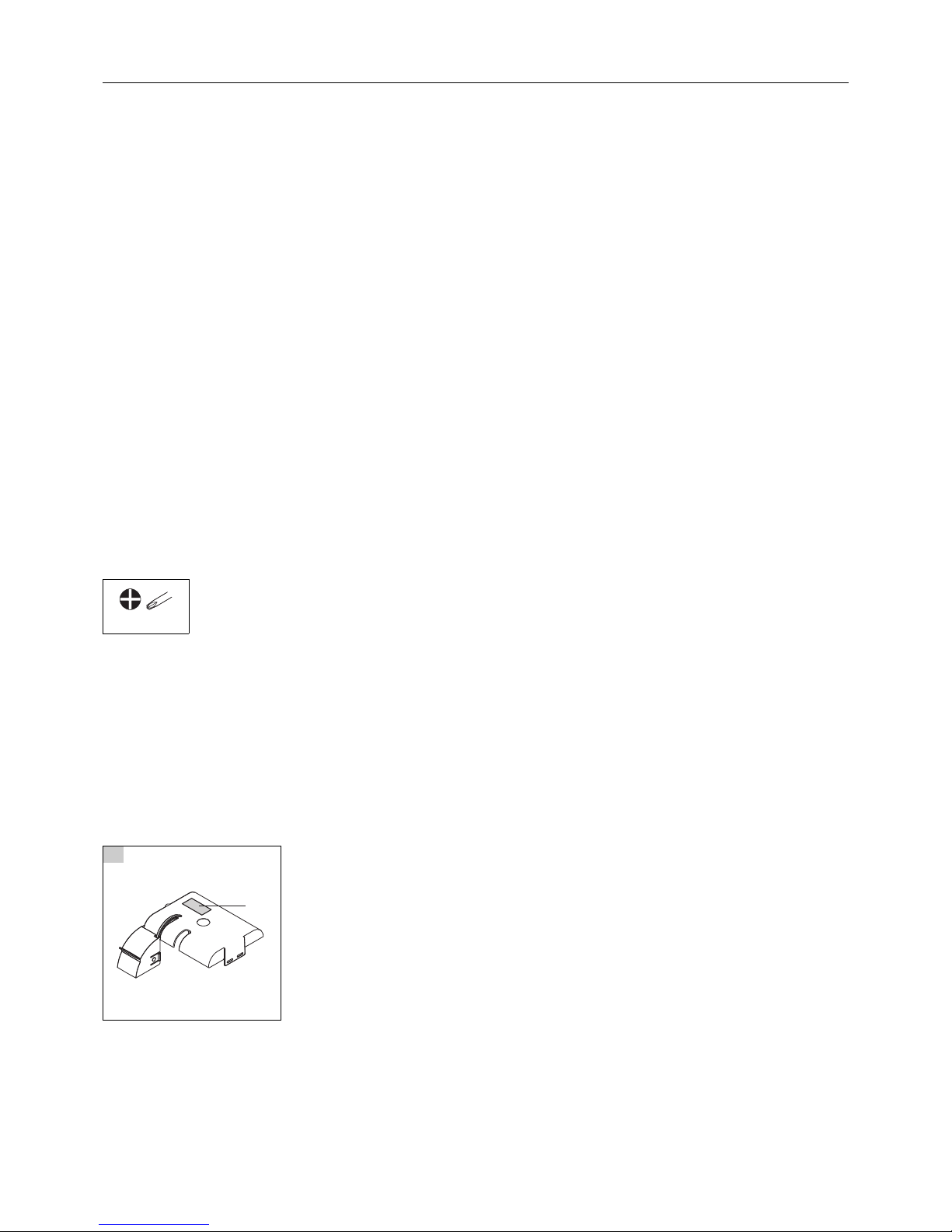
Tool List
A Activating the battery
• This instruction describes how to activate the battery on the B2 connection.
• For your information: B1 and B3 (optional) have been activated by the manufactuerer and require no consideration.
• For your information: The configuration 4 + 6 doesn‘t contain a battery on the B2 connection and require no consideration.
It is listed for your information only.
• Attention if someone enables B2 and then he doesn't connect the battery, the board may shut off unexpectedly and it will not work.
• First, connect the batteries in accordance with operating instructions.
• Next, affix the connection label (1) as indicated in the graphic below.
• Afterwards activate the battery on the B2 connection according to this Instructon.
B2 can be activated via Display or via Configuration Software Config 5800 in the internal data menu with the command BT2HE.
In both cases the numerical value has to be set 1.
• How to arrange the batteries see chapter B - chapter G.
Check the order code on your packaging note, DK5004-1 e. g. and choose the appropriate configuration.
PH2
1
A0017949
1
Activating the battery on connection B2
Endress + Hauser 3
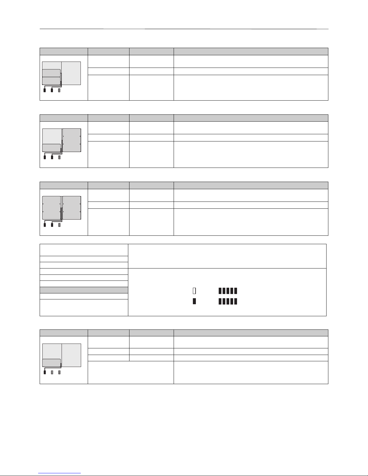
B Configuration 1 for Order-Code DK5004-1
C Configuration 2 for Order-Code DK5004-2
D Configuration 3 for Order-Code DK5004-3
E Configuration 4 for Order-Code DK5004-4
Configuration of batteries Connectors Number of batteries Battery usage
A0017127
B1 1 Backup power supply for the measuring device: B1 has been switched on by the
manufacturer and needn‘t to be considered.
B2 1 Power supply for the measuring device
B3 - Power supply for the GSM/GPRS modem
Configuration of batteries Connectors Number of batteries Battery usage
A0017128
B1 1 Backup power supply for the measuring device: B1 has been switched on by the
manufacturer and needn‘t to be considered.
B2 3 Power supply for the measuring device
B3 - Power supply for the GSM/GPRS modem
Configuration of batteries Connectors Number of batteries Battery usage
A0017129
B1 1 Backup power supply for the measuring device: B1 has been switched on by the
manufacturer and needn‘t to be considered.
B2 3 Power supply for the measuring device
B3 - Power supply for the GSM/GPRS modem
B2
B1
B1 B2 B3
B1
B1 B2 B3
B2
B1 B2 B3
B2B1
1. Where to find B2 on the display and to
set the numeric value on position 1:
2. Go back into the nominal range, press the ESC button 2 times for 2 seconds.
3. Then check the B2 state of charge of the battery in accordance with the graphic below.11- INTERNAL DATA
L2 code =
******
Load fact. data
A0019498
Save fact. data
Memory reset
B2 = 1
KF = 1.00000
KF = +1.0053
Configuration of batteries Connectors Number of batteries Battery usage
A0017130
B1 1 Backup power supply for the measuring device: B1 has been switched on by the
manufacturer and needn‘t to be considered.
B2 - Power supply for the measuring device
B3 - Power supply for the GSM/GPRS modem
Powered via external power supply Power supply for the measuring device
B1:
( )
B2:
( )
)(
)(
B1
B1 B2 B3
 Loading...