

Endress+Hauser Promag 10, Promag 50, Promag 51, Promag 53, Promag 55 Installation Instruction
...
Installation Instruction
Sensor parts remote version
Promag 10, 50, 51, 53, 55, Promass 80, 83, 84, Promag 400, Promag 800
EA00038D/06/A2/13.12
71191694
Instruction is valid for the following spare part sets:
! Note!
• The order number of the spare part set (on the packaging label) can differ from the product number (on the label directly on the spare part)!
• The order number of the relevant spare part set can be found by entering the product number of the spare part in the spare parts finder.
• We recommend that the Installation Instructions be kept with the packaging at all times.
Confirmation whether the spare part is permitted to be used with the measuring device
The spare parts set and Installation Instructions are used to replace a faulty unit with a functioning unit of the same type. Use genuine parts from
Endress+Hauser only. Only original spare parts supplied by Endress+Hauser shall be used with the measuring device. Therefore, before use, check
whether the spare part set is compatible with the measuring device.
A spare parts overview label is located in the connection compartment cover of the measuring device. If there is no label or the spare part is not
listed the appropriate spare part can also be identified via W@M Device Viewer.
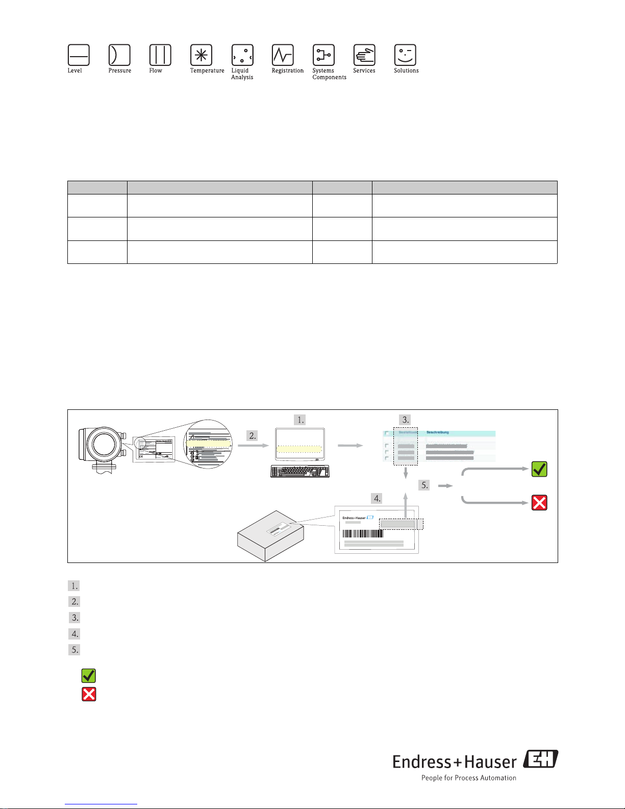
How carrying out such a check via the W@M Device Viewer is described below:
A0016264
If you have any questions, contact your Endress+Hauser service organization.
Order number Device component Order number Device component
50098705
Kit connection board,
1 × connection board, FS sensor
71039495
Kit connection board, FS HE Ex,
1 × connection board, FS sensor Ex HEC
71039494
Kit connection board, FS HE,
1 × connection board, FS sensor HEC
50098018
Kit connection board, FS
1 × connection board, FS sensor
50098706
Kit connection board, FS Ex,
1 × connection board, FS sensor Ex
71039497
Kit connection board, FS HE
1 × connection board, FS sensor HEC
Choose the Endress+Hauser Device Viewer via web browser: www.endress.com/deviceviewer
Enter the serial number (Ser. No.) of the device into the W@M Device Viewer (on the label of the transmitter), then click on "Spare parts".
The list of the available spare parts for the device is displayed.
Check the order number on the packaging label of the spare part set.
Check whether the order number of the spare part set is specified in the list displayed by the device viewer:
= YES, the spare part can be used.
= NO, the spare part may not be used.
www.endress.com/deviceviewer
Device Viewer
Ser. No.:
12345
i
i
Ser.No.:1234567890
Ser. No.:
12345
=
?
Sensor parts remote version
2 Endress + Hauser
Overview of the personnel authorized to carry out repairs
Authorization to carry out a repair depends on the approval of the measuring device. The table shows the respective group of persons for each.
! Note!
The person who carries out the repair is responsible for safety during the work, the quality of work completed and safety of the device after repair.
Safety instructions
• Check whether the spare part matches the identification label on the
measuring device, as explained on the first page.
• The spare parts set and Installation Instructions are used to replace
a faulty unit with a functioning unit of the same type.
Use genuine parts from Endress+Hauser only.
• In the case of Ex-certified measuring devices: Only open in
a de-energized state (once a delay of 10 minutes has elapsed after
switching off the power supply) or in environments which do not
have a potentially explosive atmosphere.
• The measuring device is energized. Danger: Risk of electric shock!
Open the measuring device in a de-energized state only.
• Before removing the device: set the process in a safe condition and
purge the pipe of dangerous materials.
• Hot surfaces! Risk of injury! Before commencing work, allow the
system and measuring device to cool down to a touchable
temperature.
• In the case of measuring devices in custody transfer, the custody
transfer status no longer applies once the lead seal has been removed.
• Comply with national regulations governing mounting, electrical
installation, commissioning, maintenance and repair procedures.
• Requirements with regard to specialized technical staff for the
mounting, electrical installation, commissioning, maintenance and
repair of the measuring devices:
–trained in instrument safety
–familiar with the individual operation conditions of the devices
–for Ex-certified measuring devices: also trained in explosion
protection
• Follow the Operating Instructions for the device.
• Risk of damaging electronic components! Ensure you have a working
environment protected from electrostatic discharge.
• After removing the electronics cover, there is a risk of electric shock
as shock protection is removed!
Switch off the measuring device before removing internal covers.
• Modifications to the measuring device are not permitted.
• In the case of measuring devices in safety-related applications in
accordance with IEC 61508 or IEC 61511: After repair recommission
in accordance with Operating Instructions. Document the repair
procedure.
• Only open housing for a brief period. Avoid the penetration of foreign
bodies, moisture or contaminants.
• Replace defective seal/gaskets with genuine parts from
Endress+Hauser only.
• If threads are damaged or defective, the measuring device must be
repaired.
• Threads (e.g. of the cover for the electronics and connection
compartments) must be lubricated. Use an acid-free, non-hardening
grease if an abrasion resistant dry lubricant is non-existent.
• If spacing is reduced or the dielectric strength of the measuring device
cannot be guaranteed during repair work, perform a test on
completion of the work (e.g. high-voltage test in accordance with the
manufacturer's instructions).
• Service connector:
–do not connect in potentially explosive atmospheres.
–only connect to Endress+Hauser service devices.
• Observe the instructions for transporting and returning the device
outlined in the Operating Instructions.
• If you have any questions, contact your E+H service organization.
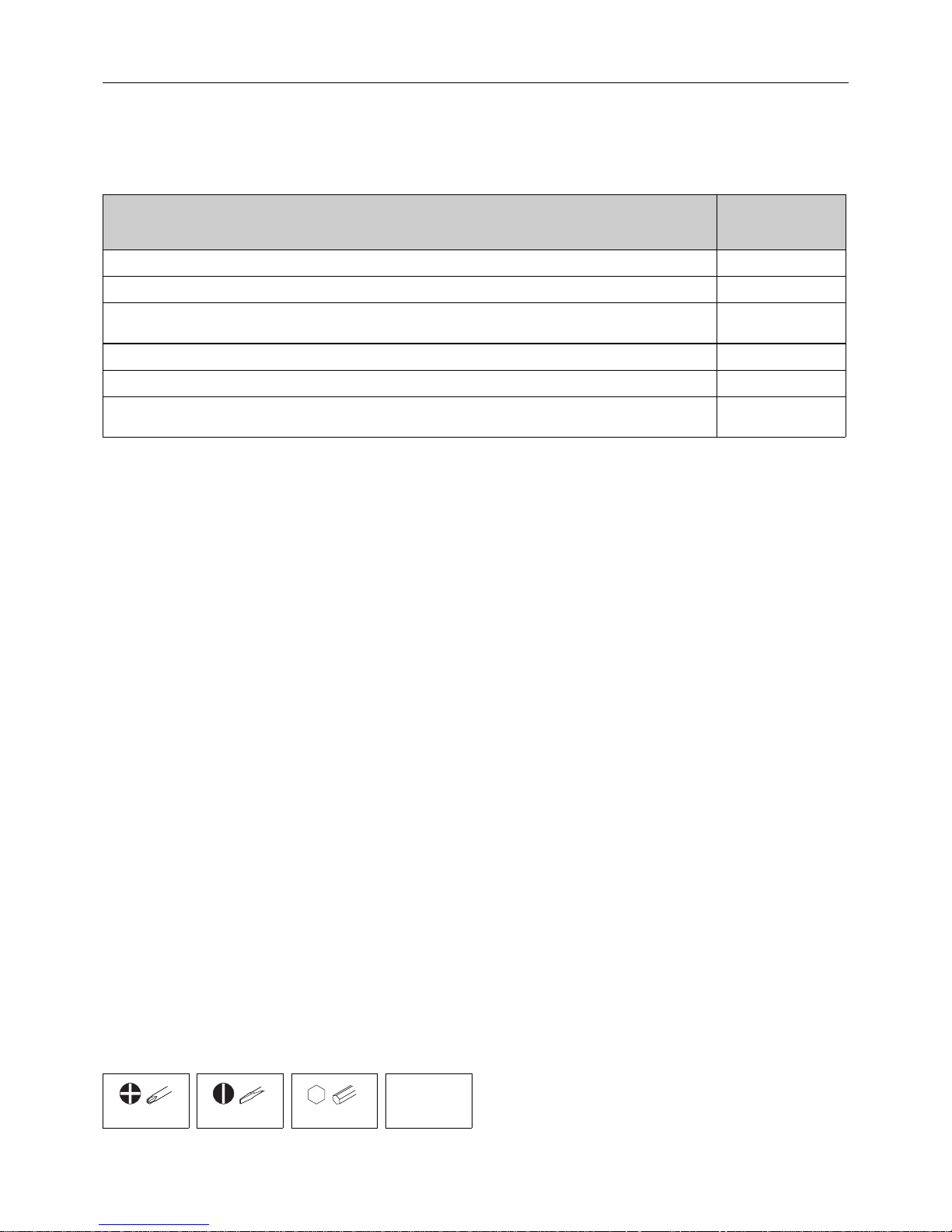
Tool List
Approval of the measuring device
Group of persons
authorized to carry
out repairs
Device without approval with spare part set: 50098705, 71039494, 50098018, 71039497 1, 2, 3
Device with approval ATEX II3G, FM/CSA Div. 2, with spare part set: 50098705, 71039494, 50098018, 71039497 1, 2, 3
Device with approval ATEX II2G, II1/2G, II2D, FM/CSA Div. 1, TIIS Zone 1, NEPSI Zone 1
with spare part set: 50098705, 71039494, 50098018, 71039497
–
Device without approval with spare part set: 50098706, 71039495 –
Device with approval ATEX II3G,
FM/CSA Div. 2, NEPSI Zone 2, with spare part set: 50098706, 71039495 –
Device with approval ATEX II2G, II1/2G, II2D, FM/CSA Div. 1, TIIS Zone 1, NEPSI Zone 1,
with spare part set: 50098706, 71039495
2, 3
1 Trained customer technician
1*Trained customer technician, trained by Endress+Hauser (for repairs carried out on devices with type approval)
2 Service technician authorized by Endress+Hauser
3 Endress+Hauser (send measuring device back to manufacturer)
PH2 0.5 × 3.5 3 mm, 8 mm
acid-free,
non hardening
grease
Sensor parts remote version
Endress + Hauser 3
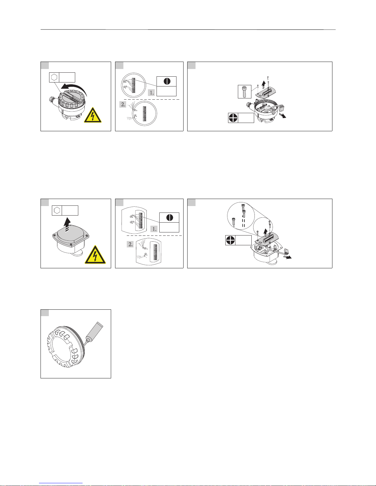
Field housing remote version
A Replacing connection board
! Note! Promass:
Non-Ex-certified measuring devices: Terminal strip is green!
Ex-certified measuring devices: Terminal strip is blue!
! Note! For wiring diagram see connection compartment cover.
Stainless Steel housing remote version
A Replacing connection board
B Re-assembly
Re-assembly is carried out in reverse order, unless otherwise instructed.
The following must be noted:
1 2 3
A0012995 A0013016 A0013017
3 mm
4
567
8
9
1
114
4
01
2
1
2
4
567
8
9
1
114
4
01
2
1
2
0.5 ×3.5
Ph2
1 2 3
A0013023 A0013025 A0013026
8 mm
4
5678911
144
01
212
4
5678911
144
01
212
0.5 ×3.5
Ph2
1
A0011687
 Loading...