

Endress+Hauser Proline Promass E 100 User Manual
TI01351D/06/EN/02.18
Заказывайте на сайте: www.tinnova.ru/endress_hauser/ || Эл. почта: info@tinnova.ru
71412496
2018-09-03
Products Solutions Services
Technical Information
Proline Promass E 100
Coriolis flowmeter
The flowmeter with minimum total cost of ownership and an ultra-compact
transmitter
Application
• Measuring principle operates independently of physical
fluid properties
• Accurate measurement of liquids and gases for a wide range
of standard applications
Device properties
• Compact dual-tube sensor
• Medium temperature up to +150 °C (+302 °F)
• Process pressure: up to 100 bar (1 450 psi)
• Robust, ultra-compact transmitter housing
• Highest degree of protection: IP69
• Local display available
such as viscosity or density
Your benefits
• Cost-effective – multi-purpose device; an alternative to
conventional volumetric flowmeters
• Fewer process measuring points – multivariable
measurement (flow, density, temperature)
•
Space‐saving installation – no in/outlet run needs
• Space‐saving transmitter – full functionality on smallest
footprint
• Time‐saving local operation without additional software and
hardware – integrated web server
• Integrated verification – Heartbeat Technology

Table of contents
Заказывайте на сайте: www.tinnova.ru/endress_hauser/ || Эл. почта: info@tinnova.ru
Proline Promass E 100
About this document ........................ 4
Symbols used ................................ 4
Function and system design ................... 5
Measuring principle ............................ 5
Measuring system ............................. 5
Equipment architecture ......................... 7
Safety ..................................... 7
Input ..................................... 8
Measured variable ............................. 8
Measuring range .............................. 8
Operable flow range ........................... 9
Output ................................... 9
Output signal ................................ 9
Signal on alarm .............................. 10
Ex connection data ........................... 12
Low flow cut off ............................. 13
Protocol-specific data .......................... 13
Power supply ............................. 23
Terminal assignment .......................... 23
Pin assignment, device plug ...................... 30
Supply voltage .............................. 32
Power consumption ........................... 33
Current consumption .......................... 33
Power supply failure .......................... 33
Electrical connection .......................... 34
Potential equalization ......................... 39
Terminals ................................. 39
Cable entries ............................... 39
Cable specification ............................ 39
Performance characteristics .................. 41
Reference operating conditions ................... 41
Maximum measured error ....................... 41
Repeatability ............................... 43
Response time .............................. 43
Influence of ambient temperature ................. 43
Influence of medium temperature .................. 43
Influence of medium pressure .................... 44
Design fundamentals .......................... 44
Shock resistance ............................. 48
Impact resistance ............................ 48
Interior cleaning ............................. 49
Electromagnetic compatibility (EMC) ............... 49
Process .................................. 49
Medium temperature range ...................... 49
Density ................................... 49
Pressure-temperature curves ..................... 50
Secondary containment ........................ 53
Rupture disk ................................ 53
Flow limit ................................. 53
Pressure loss ............................... 53
System pressure ............................. 53
Thermal insulation ........................... 54
Heating ................................... 54
Vibrations ................................. 54
Mechanical construction .................... 55
Dimensions in SI units ......................... 55
Dimensions in US units ......................... 68
Weight ................................... 76
Materials .................................. 76
Process connections ........................... 78
Surface roughness ........................... 78
Operability ............................... 78
Operating concept ............................ 78
Local display ................................ 79
Remote operation ............................ 79
Service interface ............................. 81
Certificates and approvals ................... 83
CE mark ................................... 83
C-Tick symbol ............................... 83
Ex approval ................................ 84
Sanitary compatibility ......................... 84
HART certification ............................ 84
Certification PROFIBUS ......................... 84
Certification PROFINET ........................ 85
EtherNet/IP certification ........................ 85
Modbus RS485 certification ..................... 85
Pressure Equipment Directive .................... 85
Other standards and guidelines ................... 85
Installation ............................... 45
Mounting location ............................ 45
Orientation ................................ 46
Inlet and outlet runs .......................... 47
Special mounting instructions .................... 47
Mounting Safety Barrier Promass 100 ............... 48
Environment .............................. 48
Ambient temperature range ..................... 48
Storage temperature .......................... 48
Climate class ............................... 48
Degree of protection .......................... 48
Vibration resistance ........................... 48
Ordering information ....................... 86
Application packages ....................... 86
Heartbeat Technology ......................... 86
Concentration ............................... 87
Accessories ............................... 87
Device-specific accessories ...................... 87
Communication-specific accessories ................ 87
Service-specific accessories ...................... 88
System components ........................... 88
2 Endress+Hauser

Proline Promass E 100
Заказывайте на сайте: www.tinnova.ru/endress_hauser/ || Эл. почта: info@tinnova.ru
Supplementary documentation ............... 89
Standard documentation ........................ 89
Supplementary device-dependent documentation ....... 89
Registered trademarks ...................... 90
Endress+Hauser 3
About this document
A
1.
-
.
Заказывайте на сайте: www.tinnova.ru/endress_hauser/ || Эл. почта: info@tinnova.ru
Symbols used Electrical symbols
Symbol Meaning
Proline Promass E 100
Direct current
Alternating current
Direct current and alternating current
Ground connection
A grounded terminal which, as far as the operator is concerned, is grounded via a
grounding system.
Protective Earth (PE)
A terminal which must be connected to ground prior to establishing any other
connections.
The ground terminals are situated inside and outside the device:
• Inner ground terminal: Connects the protectiv earth to the mains supply.
• Outer ground terminal: Connects the device to the plant grounding system.
Symbols for certain types of information
Symbol Meaning
Permitted
Procedures, processes or actions that are permitted.
Preferred
Procedures, processes or actions that are preferred.
Forbidden
Procedures, processes or actions that are forbidden.
Tip
Indicates additional information.
Reference to documentation.
Reference to page.
Reference to graphic.
Visual inspection.
Symbols in graphics
Symbol Meaning
1, 2, 3, ... Item numbers
, 2., 3., … Series of steps
A, B, C, ... Views
A-A, B-B, C-C, ... Sections
Hazardous area
Safe area (non-hazardous area)
Flow direction
4 Endress+Hauser
Proline Promass E 100
21 3
Заказывайте на сайте: www.tinnova.ru/endress_hauser/ || Эл. почта: info@tinnova.ru
Function and system design
Measuring principle
The measuring principle is based on the controlled generation of Coriolis forces. These forces are
always present in a system when both translational and rotational movements are superimposed.
Fc = 2 · ∆m (ν · ω)
Fc = Coriolis force
m = moving mass
∆
ω = rotational velocity
ν = radial velocity in rotating or oscillating system
The amplitude of the Coriolis force depends on the moving mass ∆m, its velocity ν in the system and
thus on the mass flow. Instead of a constant rotational velocity ω, the sensor uses oscillation.
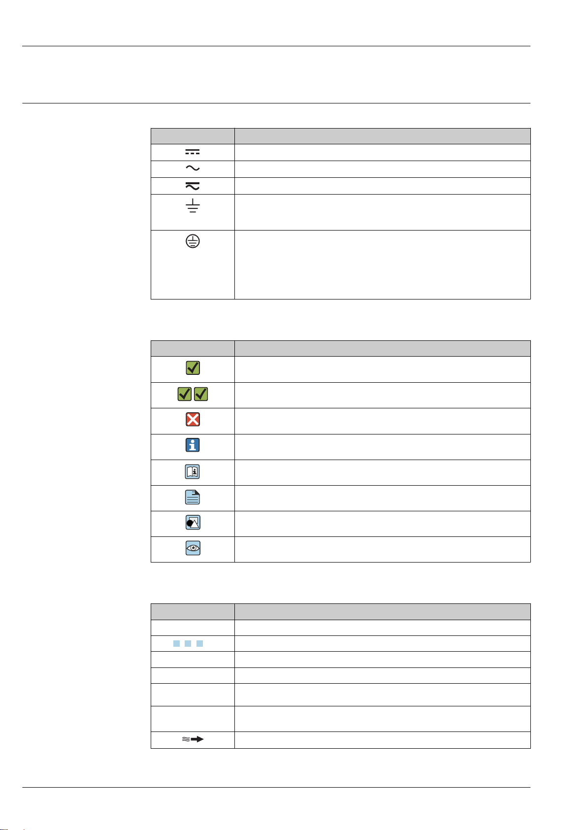
In the sensor, two parallel measuring tubes containing flowing fluid oscillate in antiphase, acting like
a tuning fork. The Coriolis forces produced at the measuring tubes cause a phase shift in the tube
oscillations (see illustration):
• At zero flow (when the fluid is at a standstill) the two tubes oscillate in phase (1).
Mass flow causes deceleration of the oscillation at the inlet of the tubes (2) and acceleration at the
•
outlet (3).
Measuring system
A0028850
The phase difference (A-B) increases with increasing mass flow. Electrodynamic sensors register the
tube oscillations at the inlet and outlet. System balance is ensured by the antiphase oscillation of the
two measuring tubes. The measuring principle operates independently of temperature, pressure,
viscosity, conductivity and flow profile.
Density measurement
The measuring tube is continuously excited at its resonance frequency. A change in the mass and
thus the density of the oscillating system (comprising measuring tube and fluid) results in a
corresponding, automatic adjustment in the oscillation frequency. Resonance frequency is thus a
function of medium density. The microprocessor utilizes this relationship to obtain a density signal.
Volume measurement
Together with the measured mass flow, this is used to calculate the volume flow.
Temperature measurement
The temperature of the measuring tube is determined in order to calculate the compensation factor
due to temperature effects. This signal corresponds to the process temperature and is also available
as an output signal.
The device consists of a transmitter and a sensor. If a device with Modbus RS485 intrinsically safe is
ordered, the Safety Barrier Promass 100 is part of the scope of supply and must be implemented to
operate the device.
The device is available as a compact version:
The transmitter and sensor form a mechanical unit.
Endress+Hauser 5
Transmitter
Заказывайте на сайте: www.tinnova.ru/endress_hauser/ || Эл. почта: info@tinnova.ru
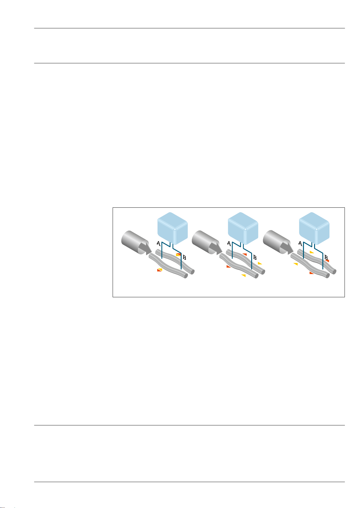
Promass 100 Device versions and materials:
• Compact, aluminum, coated:
Aluminum, AlSi10Mg, coated
• Compact, hygienic, stainless:
Hygienic version, stainless steel 1.4301 (304)
Ultra-compact, hygienic, stainless:
•
A0016693
A0016694
A0016695
Hygienic version, stainless steel 1.4301 (304)
Configuration:
• Via operating tools (e.g. FieldCare, DeviceCare)
• Additionally for device version with local display:
Via Web browser (e.g. Microsoft Internet Explorer)
• Also for device version with 4-20 mA HART, pulse/frequency/switch
output:
Via Web browser (e.g. Microsoft Internet Explorer)
• Also for device version with EtherNet/IP output:
– Via Web browser (e.g. Microsoft Internet Explorer)
– Via Add-on Profile Level 3 for automation system from Rockwell
Automation
– Via Electronic Data Sheet (EDS)
• Also for device version with PROFINET output:
– Via Web browser (e.g. Microsoft Internet Explorer)
– Via device master file (GSD)
Proline Promass E 100
Sensor
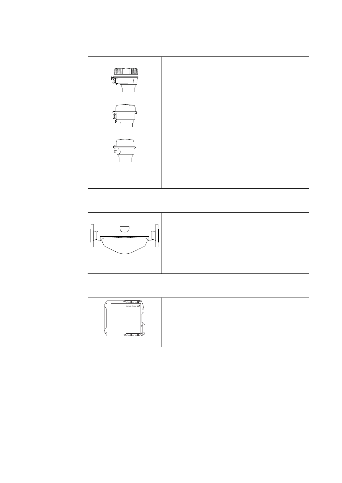
Promass E • For standard applications where stable and reliable measurements are
required
• Simultaneous measurement of flow, volume flow, density and
temperature (multivariable)
• Immune to process influences
Nominal diameter range: DN 8 to 80 (³⁄₈ to 3")
•
• Materials:
A0030940
– Sensor: stainless steel, 1.4301 (304)
– Measuring tubes: stainless steel, 1.4539 (904L)
– Process connections: stainless steel, 1.4404 (316/316L)
Safety Barrier Promass 100
• Dual-channel safety barrier for installation in non-hazardous locations
or zone 2/div. 2:
– Channel 1: DC 24 V power supply
– Channel 2: Modbus RS485
In addition to current, voltage and power limitation, it offers galvanic
•
isolation of circuits for explosion protection.
• Easy top-hat rail mounting (DIN 35 mm) for installation in control
A0016763
cabinets
6 Endress+Hauser
Proline Promass E 100
2 3
7
86
9
10
11
4
1
5
Заказывайте на сайте: www.tinnova.ru/endress_hauser/ || Эл. почта: info@tinnova.ru
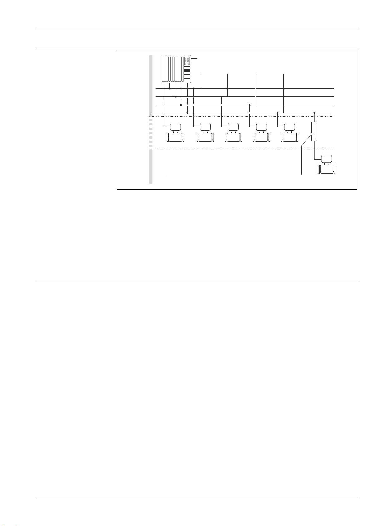
Equipment architecture
1 Possibilities for integrating measuring devices into a system
Control system (e.g. PLC)
1
2 EtherNet/IP
3 PROFIBUS DP
4 PROFINET
5 Modbus RS485
6 4-20 mA HART, pulse/frequency/switch output
7 Safety Barrier Promass 100
8 Modbus RS485 intrinsically safe
9 Non-hazardous area
10 Non-hazardous area and Zone 2/Div. 2
11 Hazardous area and Zone 1/Div. 1
A0016779
Safety IT security
We only provide a warranty if the device is installed and used as described in the Operating
Instructions. The device is equipped with security mechanisms to protect it against any inadvertent
changes to the device settings.
IT security measures in line with operators' security standards and designed to provide additional
protection for the device and device data transfer must be implemented by the operators themselves.
Endress+Hauser 7
Input
Заказывайте на сайте: www.tinnova.ru/endress_hauser/ || Эл. почта: info@tinnova.ru
Measured variable Direct measured variables
• Mass flow
•
Density
• Temperature
Calculated measured variables
• Volume flow
• Corrected volume flow
• Reference density
Measuring range Measuring ranges for liquids
Proline Promass E 100
DN Measuring range full scale values
[mm] [in] [kg/h] [lb/min]
8 ³⁄₈ 0 to 2 000 0 to 73.50
15 ½ 0 to
25 1 0 to 18 000 0 to 661.5
40 1½ 0 to 45 000 0 to 1 654
50 2 0 to 70 000 0 to 2 573
80 3 0 to 180 000 0 to 6 615
6 500 0 to 238.9
min(F)
to
max(F)
Measuring ranges for gases
The full scale values depend on the density of the gas and can be calculated with the formula below:
=
max(G)
max(G)
max(F)
<
max(G)
ρ
G
x Constant dependent on nominal diameter
max(F)
max(F)
· ρG : x
Maximum full scale value for gas [kg/h]
Maximum full scale value for liquid [kg/h]
can never be greater than
max(G)
Gas density in [kg/m³] at operating conditions
max(F)
DN x
[mm] [in] [kg/m3]
8 ³⁄₈ 85
15 ½ 110
25 1 125
40 1½ 125
50 2 125
80 3 155
To calculate the measuring range, use the Applicator sizing tool → 88
Calculation example for gas
• Sensor: Promass E, DN 50
Gas: Air with a density of 60.3 kg/m³ (at 20 °C and 50 bar)
•
• Measuring range (liquid): 70 000 kg/h
• x = 125 kg/m³ (for Promass E, DN 50)
8 Endress+Hauser

Proline Promass E 100
Заказывайте на сайте: www.tinnova.ru/endress_hauser/ || Эл. почта: info@tinnova.ru
Maximum possible full scale value:
max(G)
=
· ρG : x = 70 000
max(F)
Recommended measuring range
"Flow limit" section → 53
kg/h · 60.3 kg/m³ : 125 kg/m³ = 33 800 kg/h
Operable flow range
Over 1000 : 1.
Flow rates above the preset full scale value do not override the electronics unit, with the result that
the totalizer values are registered correctly.
Output
Output signal HART current output
Current output 4-20 mA HART (active)
Maximum output values • DC
Load 0 to 700 Ω
Resolution 0.38 µA
Damping Adjustable:
Assignable measured
variables
24 V (no flow)
• 22.5 mA
0.07 to 999 s
• Mass flow
• Volume flow
• Corrected volume flow
• Density
• Reference density
• Temperature
The range of options increases if the measuring device has one or more
application packages.
Pulse/frequency/switch output
Function Can be set to pulse, frequency or switch output
Version Passive, open collector
Maximum input values • DC 30 V
• 25 mA
Voltage drop For
Pulse output
Pulse width Adjustable: 0.05 to 2 000 ms
Maximum pulse rate 10 000 Impulse/s
Pulse value Adjustable
Assignable measured
variables
Frequency output
Output frequency Adjustable: 0 to 10 000 Hz
Damping Adjustable: 0 to 999 s
Pulse/pause ratio 1:1
25 mA: ≤ DC 2 V
• Mass flow
• Volume flow
• Corrected volume flow
Endress+Hauser 9

Proline Promass E 100
Заказывайте на сайте: www.tinnova.ru/endress_hauser/ || Эл. почта: info@tinnova.ru
Assignable measured
variables
Switch output
Switching behavior Binary, conductive or non-conductive
Switching delay Adjustable: 0 to 100 s
Number of switching
cycles
Assignable functions • Off
• Mass flow
• Volume flow
• Corrected volume flow
Density
•
• Reference density
• Temperature
The range of options increases if the measuring device has one or more
application packages.
Unlimited
• On
• Diagnostic behavior
• Limit value
– Mass flow
– Volume flow
– Corrected volume flow
– Density
– Reference density
– Temperature
– Totalizer 1-3
• Flow direction monitoring
• Status
– Partially filled pipe detection
– Low flow cut off
The range of options increases if the measuring device has one or more
application packages.
Signal on alarm
PROFIBUS DP
Signal encoding NRZ code
Data transfer 9.6 kBaud…12 MBaud
Modbus RS485
Physical interface In accordance with EIA/TIA-485-A standard
Terminating resistor • For device version used in non-hazardous areas or Zone 2/Div. 2: integrated
and can be activated via DIP switches on the transmitter electronics module
• For device version used in intrinsically safe areas: integrated and can be
activated via DIP switches on the Safety Barrier Promass 100
EtherNet/IP
Standards In accordance with IEEE 802.3
PROFINET
Standards In accordance with IEEE 802.3
Depending on the interface, failure information is displayed as follows:
10 Endress+Hauser

Proline Promass E 100
Заказывайте на сайте: www.tinnova.ru/endress_hauser/ || Эл. почта: info@tinnova.ru
Current output 4 to 20 mA
4 to 20 mA
Failure mode Choose from:
• 4 to 20 mA in accordance with NAMUR recommendation NE 43
4 to 20 mA in accordance with US
•
• Min. value: 3.59 mA
• Max. value: 22.5 mA
• Freely definable value between: 3.59 to 22.5 mA
• Actual value
• Last valid value
Pulse/frequency/switch output
Pulse output
Failure mode Choose from:
• Actual value
• No pulses
Frequency output
Failure mode Choose from:
Switch output
Failure mode Choose from:
Actual value
•
• 0 Hz
• Defined value: 0 to 12 500 Hz
• Current status
• Open
• Closed
PROFIBUS DP
Status and alarm
messages
Diagnostics in accordance with PROFIBUS PA Profile 3.02
Modbus RS485
Failure mode Choose from:
• NaN value instead of current value
• Last valid value
EtherNet/IP
Device diagnostics Device condition can be read out in Input Assembly
PROFINET
Device diagnostics According to "Application Layer protocol for decentralized periphery", Version 2.3
Endress+Hauser 11

Local display
Заказывайте на сайте: www.tinnova.ru/endress_hauser/ || Эл. почта: info@tinnova.ru
Plain text display With information on cause and remedial measures
Backlight Red backlighting indicates a device error.
Status signal as per NAMUR recommendation NE 107
Interface/protocol
• Via digital communication:
– HART protocol
PROFIBUS DP
–
– Modbus RS485
– EtherNet/IP
– PROFINET
• Via service interface
CDI-RJ45 service interface
Plain text display With information on cause and remedial measures
Proline Promass E 100
Ex connection data
Additional information on remote operation → 79
Web server
Plain text display With information on cause and remedial measures
Light emitting diodes (LED)
Status information Status indicated by various light emitting diodes
The following information is displayed depending on the device version:
•
Supply voltage active
Data transmission active
•
•
Device alarm/error has occurred
• EtherNet/IP network available
• EtherNet/IP connection established
• PROFINET network available
• PROFINET connection established
• PROFINET blinking feature
These values only apply for the following device version:
Order code for "Output", option M "Modbus RS485", for use in intrinsically safe areas
Safety Barrier Promass 100
Safety-related values
Terminal numbers
Supply voltage Signal transmission
2 (L-) 1 (L+) 26 (A) 27 (B)
U
nom
U
= AC 260 V
max
= DC 24 V
U
nom
U
= AC 260 V
max
= DC 5 V
12 Endress+Hauser

Proline Promass E 100
Заказывайте на сайте: www.tinnova.ru/endress_hauser/ || Эл. почта: info@tinnova.ru
Intrinsically safe values
Terminal numbers
Supply voltage Signal transmission
20 (L-) 10 (L+) 62 (A) 72 (B)
Uo = 16.24 V
Io = 623 mA
1)
With IIC
For an overview and for information on the interdependencies between the gas group - sensor - nominal
diameter, see the "Safety Instructions" (XA) document for the measuring device
1) The gas group depends on the sensor and nominal diameter ff.
: Lo = 92.8 µH, Co = 0.433 μF, Lo/Ro = 14.6 μH/Ω
With IIB: Lo= 372 µH, Co = 2.57 μF, Lo/Ro = 58.3 μH/Ω
Po = 2.45
W
Transmitter
Intrinsically safe values
• Option BM: ATEX II2G + IECEx Z1 Ex ia, II2D Ex tb
• Option BO: ATEX II1/2G + IECEx Z0/Z1 Ex ia, II2D
Option BQ: ATEX II1/2G + IECEx Z0/Z1 Ex ia
•
• Option BU: ATEX II2G + IECEx Z1 Ex ia
• Option C2: CSA C/US IS Cl. I, II, III Div. 1
• Option 85: ATEX II2G + IECEx Z1 Ex ia + CSA C/US
IS Cl. I, II, III Div. 1
Low flow cut off
Protocol-specific data HART
The switch points for low flow cut off are user-selectable.
Manufacturer ID 0x11
Device type ID 0x4A
HART protocol revision 7
Device description files
(DTM, DD)
HART load Min. 250 Ω
Order code for
"Approval"
For an overview and for information on the interdependencies between the gas group - sensor - nominal
diameter, see the "Safety Instructions" (XA) document for the measuring device
Information and files under:
www.endress.com
Supply voltage Signal transmission
20 (L-) 10 (L+) 62 (A) 72 (B)
Terminal numbers
Ui = 16.24 V
Ii = 623 mA
Pi = 2.45 W
Li = 0 µH
Ci = 6 nF
Endress+Hauser 13

Dynamic variables Read out the dynamic variables: HART command 3
Заказывайте на сайте: www.tinnova.ru/endress_hauser/ || Эл. почта: info@tinnova.ru
The measured variables can be freely assigned to the dynamic variables.
Measured variables for PV (primary dynamic variable)
• Mass flow
• Volume flow
Corrected volume flow
•
• Density
• Reference density
• Temperature
Measured variables for SV, TV, QV (secondary, tertiary and quaternary
dynamic variable)
• Mass flow
• Volume flow
• Corrected volume flow
• Density
• Reference density
• Temperature
• Totalizer 1
• Totalizer 2
• Totalizer 3
The range of options increases if the measuring device has one or more
application packages.
Heartbeat Technology application package
Additional measured variables are available with the Heartbeat Technology
application package:
Oscillation amplitude 0
Device variables Read out the device variables: HART command 9
The device variables are permanently assigned.
A maximum of 8 device variables can be transmitted:
• 0 = mass flow
• 1 = volume flow
• 2 = corrected volume flow
• 3 = density
• 4 = reference density
• 5 = temperature
• 6 = totalizer 1
• 7 = totalizer 2
• 8 = totalizer 3
• 13 = target mass flow
• 14 = carrier mass flow
• 15 = concentration
Proline Promass E 100
PROFIBUS DP
Manufacturer ID 0x11
Ident number 0x1561
Profile version 3.02
Device description files (GSD,
DTM, DD)
Information and files under:
• www.endress.com
On the product page for the device: Documents/Software → Device drivers
• www.profibus.org
14 Endress+Hauser

Proline Promass E 100
Заказывайте на сайте: www.tinnova.ru/endress_hauser/ || Эл. почта: info@tinnova.ru
Output values
(from measuring device to
automation system)
Input values
(from automation system to
measuring device)
Supported functions • Identification & Maintenance
Configuration of the device
address
Analog input 1 to 8
• Mass flow
• Volume flow
Corrected volume flow
•
• Target mass flow
• Carrier mass flow
• Density
• Reference density
• Concentration
• Temperature
• Carrier pipe temperature
• Electronic temperature
• Oscillation frequency
• Oscillation amplitude
• Frequency fluctuation
• Oscillation damping
• Tube damping fluctuation
• Signal asymmetry
• Exciter current
Digital input 1 to 2
• Partially filled pipe detection
• Low flow cut off
Totalizer 1 to 3
• Mass flow
• Volume flow
• Corrected volume flow
Analog output 1 to 3 (fixed assignment)
• Pressure
• Temperature
• Reference density
Digital output 1 to 3 (fixed assignment)
• Digital output 1: switch positive zero return on/off
• Digital output 2: perform zero point adjustment
• Digital output 3: switch switch output on/off
Totalizer 1 to 3
• Totalize
• Reset and hold
• Preset and hold
• Stop
• Operating mode configuration:
– Net flow total
– Forward flow total
– Reverse flow total
Simplest device identification on the part of the control system and
nameplate
• PROFIBUS upload/download
Reading and writing parameters is up to ten times faster with PROFIBUS
upload/download
• Condensed status
Simplest and self-explanatory diagnostic information by categorizing
diagnostic messages that occur
• DIP switches on the I/O electronics module
• Via operating tools (e.g. FieldCare)
Modbus RS485
Protocol Modbus Applications Protocol Specification V1.1
Device type Slave
Slave address range 1 to 247
Broadcast address range 0
Endress+Hauser 15

Proline Promass E 100
Заказывайте на сайте: www.tinnova.ru/endress_hauser/ || Эл. почта: info@tinnova.ru
Function codes • 03: Read holding register
• 04: Read input register
• 06: Write single registers
08: Diagnostics
•
• 16: Write multiple registers
• 23: Read/write multiple registers
Broadcast messages Supported by the following function codes:
• 06: Write single registers
• 16: Write multiple registers
• 23: Read/write multiple registers
Supported baud rate • 1 200 BAUD
• 2 400 BAUD
• 4 800 BAUD
• 9 600 BAUD
• 19 200 BAUD
• 38 400 BAUD
• 57 600 BAUD
• 115 200 BAUD
Data transfer mode • ASCII
• RTU
Data access Each device parameter can be accessed via Modbus RS485.
For Modbus register information, see "Description of device parameters"
documentation
EtherNet/IP
Protocol • The CIP Networks Library Volume 1: Common Industrial Protocol
• The CIP Networks Library Volume 2: EtherNet/IP Adaptation of CIP
Communication type • 10Base-T
Device profile Generic device (product type: 0x2B)
Manufacturer ID 0x49E
Device type ID 0x104A
Baud rates Automatic ¹⁰⁄₁₀₀ Mbit with half-duplex and full-duplex detection
Polarity Auto-polarity for automatic correction of crossed TxD and RxD pairs
Supported CIP connections Max. 3 connections
Explicit connections Max. 6 connections
I/O connections Max. 6 connections (scanner)
Configuration options for
measuring device
Configuration of the EtherNet
interface
Configuration of the device
address
Device Level Ring (DLR) No
100Base-TX
•
• DIP switches on the electronics module for IP addressing
• Manufacturer-specific software (FieldCare)
• Add-on Profile Level 3 for Rockwell Automation control systems
• Web browser
• Electronic Data Sheet (EDS) integrated in the measuring device
• Speed: 10 MBit, 100 MBit, auto (factory setting)
• Duplex: half-duplex, full-duplex, auto (factory setting)
• DIP switches on the electronics module for IP addressing (last octet)
• DHCP
• Manufacturer-specific software (FieldCare)
• Add-on Profile Level 3 for Rockwell Automation control systems
• Web browser
• EtherNet/IP tools, e.g. RSLinx (Rockwell Automation)
16 Endress+Hauser
Proline Promass E 100
Заказывайте на сайте: www.tinnova.ru/endress_hauser/ || Эл. почта: info@tinnova.ru
Fix Input
RPI 5 ms to 10 s (factory setting: 20 ms)
Exclusive Owner Multicast Instance Size [byte]
Instance configuration: 0x68 398
O → T configuration: 0x66 64
T → O configuration: 0x64 44
Exclusive Owner Multicast Instance Size [byte]
Instance configuration: 0x69 -
O → T configuration: 0x66 64
T → O configuration: 0x64 44
Input only Multicast Instance Size [byte]
Instance configuration: 0x68 398
O → T configuration: 0xC7 -
T → O configuration: 0x64 44
Input only Multicast Instance Size [byte]
Instance configuration: 0x69 -
O → T configuration: 0xC7 -
T → O configuration: 0x64 44
Input Assembly • Current device diagnostics
• Mass flow
• Volume flow
Corrected volume flow
•
• Density
• Reference density
• Temperature
• Totalizer 1
• Totalizer 2
• Totalizer 3
Configurable Input
RPI 5 ms to 10 s (factory setting: 20 ms)
Exclusive Owner Multicast Instance Size [byte]
Instance configuration: 0x68 398
O → T configuration: 0x66 64
T → O configuration: 0x65 88
Exclusive Owner Multicast Instance Size [byte]
Instance configuration: 0x69 -
O → T configuration: 0x66 64
T → O configuration: 0x65 88
Input only Multicast Instance Size [byte]
Instance configuration: 0x68 398
O → T configuration: 0xC7 -
T → O configuration: 0x65 88
Input only Multicast Instance Size [byte]
Instance configuration: 0x69 -
O → T configuration: 0xC7 -
T → O configuration: 0x65 88
Endress+Hauser 17

Proline Promass E 100
Заказывайте на сайте: www.tinnova.ru/endress_hauser/ || Эл. почта: info@tinnova.ru
Configurable Input Assembly • Current device diagnostics
• Mass flow
• Volume flow
Corrected volume flow
•
• Density
• Reference density
• Temperature
• Totalizer 1
• Totalizer 2
• Totalizer 3
The range of options increases if the measuring device has one or
more application packages.
Fix Output
Output Assembly • Activation of reset totalizers 1-3
• Activation of pressure compensation
• Activation of reference density compensation
• Activation of temperature compensation
• Reset totalizers 1-3
• External pressure value
• Pressure unit
• External reference density
• Reference density unit
• External temperature
• Temperature unit
Configuration
Configuration Assembly Only the most common configurations are listed below.
• Software write protection
• Mass flow unit
• Mass unit
• Volume flow unit
• Volume unit
• Corrected volume flow unit
• Corrected volume unit
• Density unit
• Reference density unit
• Temperature unit
• Pressure unit
• Length
• Totalizer 1-3:
– Assignment
– Unit
– Operating mode
– Failsafe mode
• Alarm delay
PROFINET
Protocol "Application layer protocol for decentral device periphery and distributed
automation", version 2.3
Conformity class B
Communication type 100 MBit/s
Device profile Application interface identifier 0xF600
Generic device
Manufacturer ID 0x11
Device type ID 0x844A
Device description files (GSD,
DTM)
Baud rates Automatic 100 Mbit/s with full-duplex detection
Information and files under:
• www.endress.com
On the product page for the device: Documents/Software → Device drivers
• www.profibus.org
18 Endress+Hauser

Proline Promass E 100
Заказывайте на сайте: www.tinnova.ru/endress_hauser/ || Эл. почта: info@tinnova.ru
Cycle times From 8 ms
Polarity Auto-polarity for automatic correction of crossed TxD and RxD pairs
Supported connections • 1 x AR (Application Relation)
• 1 x Input CR (Communication Relation)
• 1 x Output CR (Communication Relation)
1 x Alarm CR (Communication Relation)
•
Configuration options for
measuring device
Configuration of the device
name
Output values
(from measuring device to
automation system)
• DIP switches on the electronics module, for device name assignment (last
part)
• Manufacturer-specific software (FieldCare, DeviceCare)
• Web browser
• Device master file (GSD), can be read out via the integrated Web server of
the measuring device
• DIP switches on the electronics module, for device name assignment (last
part)
• DCP protocol
Analog Input module (slot 1 to 14)
• Mass flow
• Volume flow
• Corrected volume flow
• Target mass flow
• Carrier mass flow
• Density
• Reference density
• Concentration
• Temperature
• Carrier pipe temperature
• Electronic temperature
• Oscillation frequency
• Oscillation amplitude
• Frequency fluctuation
• Oscillation damping
• Tube damping fluctuation
• Signal asymmetry
• Exciter current
Discrete Input module (slot 1 to 14)
• Empty pipe detection
• Low flow cut off
Diagnostics Input module (slot 1 to 14)
• Last diagnostics
• Current diagnosis
Totalizer 1 to 3 (slot 15 to 17)
• Mass flow
• Volume flow
• Corrected volume flow
Heartbeat Verification module (fixed assignment)
Verification status (slot 23)
The range of options increases if the measuring device has one or more
application packages.
Endress+Hauser 19
Proline Promass E 100
Заказывайте на сайте: www.tinnova.ru/endress_hauser/ || Эл. почта: info@tinnova.ru
Input values
(from automation system to
measuring device)
Supported functions • Identification & Maintenance
Analog Output module (fixed assignment)
• External pressure (slot 18)
• External temperature (slot 19)
External reference density (slot 20)
•
Discrete Output module (fixed assignment)
• Activate/deactivate positive zero return (slot 21)
• Perform zero point adjustment (slot 22)
Totalizer 1 to 3 (slot 15 to 17)
• Totalize
• Reset and hold
• Preset and hold
• Stop
• Operating mode configuration:
– Net flow total
– Forward flow total
– Reverse flow total
Heartbeat Verification module (fixed assignment)
Start verification (slot 23)
The range of options increases if the measuring device has one or more
application packages.
Simple device identification via:
– Control system
– Nameplate
• Measured value status
The process variables are communicated with a measured value status
• Blinking feature via the local display for simple device identification and
assignment
Administration of software options
Input/output value Process variable Category Slot
Output value Mass flow Process variable 1 to 14
Volume flow
Corrected volume flow
Density
Reference density
Temperature
Electronic temperature
Oscillation frequency
Frequency fluctuation
Oscillation damping
Oscillation frequency
Signal asymmetry
Exciter current
Empty pipe detection
Low flow cut off
Current device diagnostics
Previous device diagnostics
Output value Target mass flow Concentration
Carrier mass flow
Concentration
Output value Oscillation damping 1 Heartbeat
1)
2)
1 to 14
1 to 14
20 Endress+Hauser

Proline Promass E 100
Заказывайте на сайте: www.tinnova.ru/endress_hauser/ || Эл. почта: info@tinnova.ru
Input/output value Process variable Category Slot
Oscillation frequency 1
Oscillation amplitude 0
Oscillation amplitude 1
Frequency fluctuation 1
Tube damping fluctuation 1
Exciter current 1
Input value External density Process monitoring 18
External temperature 19
External reference density 20
Flow override 21
Zero point adjustment 22
Status verification Heartbeat Verification 23
1) Only available with the "Concentration" application package.
2) Only available with the "Heartbeat" application package.
Endress+Hauser 21

Startup configuration
Заказывайте на сайте: www.tinnova.ru/endress_hauser/ || Эл. почта: info@tinnova.ru
Proline Promass E 100
Startup configuration
(NSU)
If startup configuration is enabled, the configuration of the most important
device parameters is taken from the automation system and used.
The following configuration is taken from the automation system:
• Management
– Software revision
Write protection
–
• System units
– Mass flow
– Mass
– Volume flow
– Volume
– Corrected volume flow
– Corrected volume
– Density
– Reference density
– Temperature
– Pressure
• Concentration application package
– Coefficients A0 to A4
– Coefficients B1 to B3
• Sensor adjustment
• Process parameter
– Damping (flow, density, temperature)
– Flow override
• Low flow cut off
– Assign process variable
– Switch-on/switch-off point
– Pressure shock suppression
• Empty pipe detection
– Assign process variable
– Limit values
– Response time
– Max. damping
• Corrected volume flow calculation
– External reference density
– Fixed reference density
– Reference temperature
– Linear expansion coefficient
– Square expansion coefficient
• Measuring mode
– Medium
– Gas type
– Reference sound velocity
– Temperature coefficient sound velocity
• External compensation
– Pressure compensation
– Pressure value
– External pressure
• Diagnostic settings
• Diagnostic behavior for diverse diagnostic information
22 Endress+Hauser
Proline Promass E 100
A
B
C
2
2.1 2.2
3
3.1 3.2
1
1.1 1.2 1.3
4
4.2
4.1
Заказывайте на сайте: www.tinnova.ru/endress_hauser/ || Эл. почта: info@tinnova.ru
Power supply
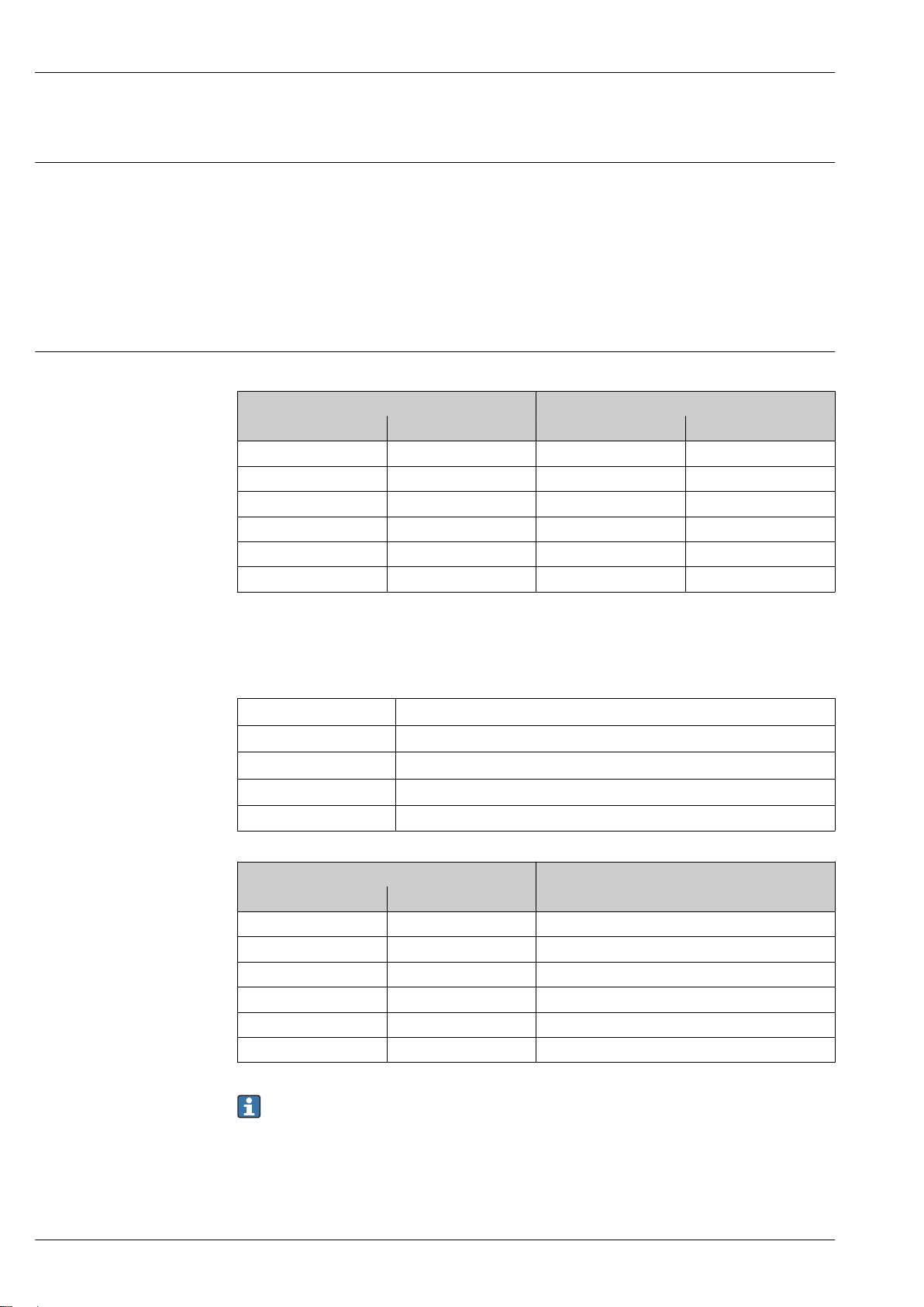
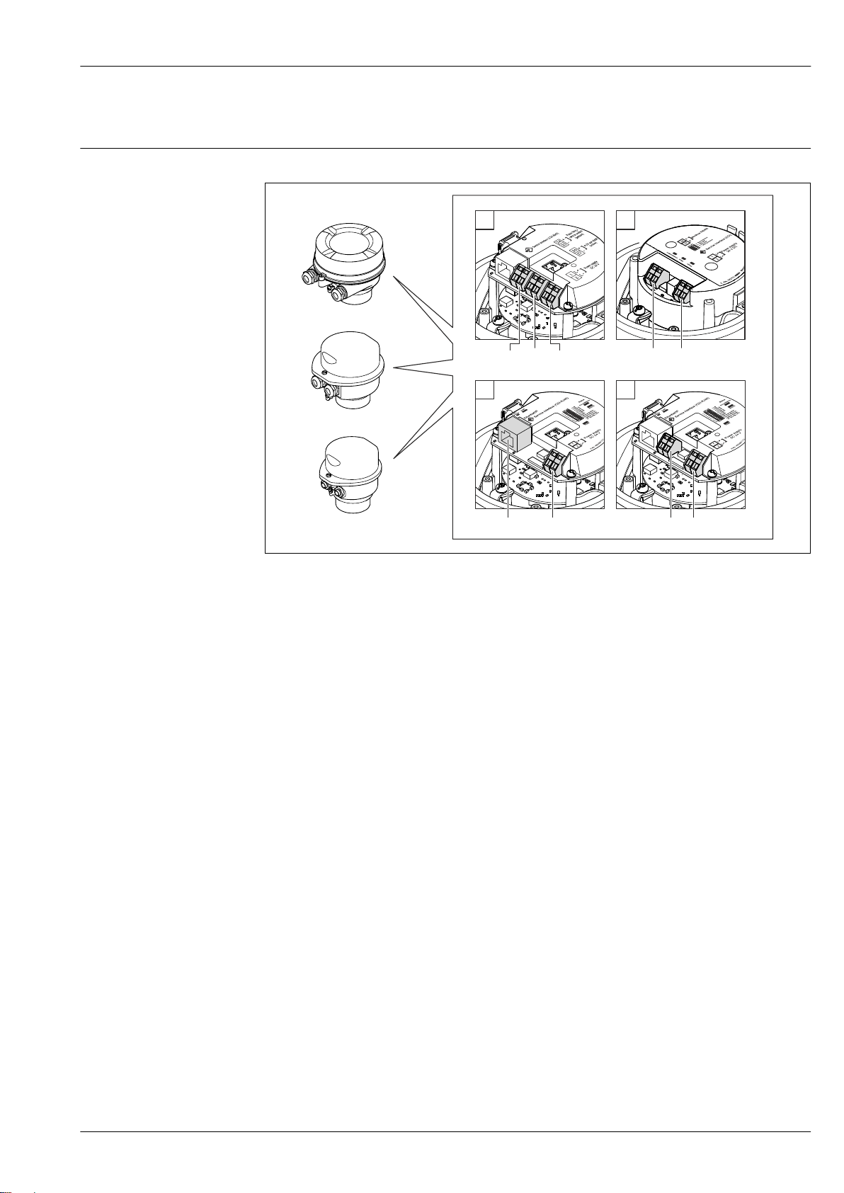
Terminal assignment Overview: housing version and connection versions
A0016770
A Housing version: compact, aluminum coated
B Housing version: compact, hygienic, stainless
C Housing version: ultra-compact, hygienic, stainless
1 Connection version: 4-20 mA HART, pulse/frequency/switch output
1.1 Signal transmission: pulse/frequency/switch output
1.2 Signal transmission: 4-20 mA HART
1.3 Supply voltage
2 Connection version: Modbus RS485
2.1 Signal transmission
2.2 Supply voltage
3 Connection versions: EtherNet/IP and PROFINET
3.1 Signal transmission
3.2 Supply voltage
4 Connection version: PROFIBUS DP
4.1 Signal transmission
4.2 Supply voltage
Transmitter
Connection version 4-20 mA HART with pulse/frequency/switch output
Order code for "Output", option B
Endress+Hauser 23
Proline Promass E 100
L
L
26
27
+
_
24
25
1
2
+
_
+
_
1
2
3
Заказывайте на сайте: www.tinnova.ru/endress_hauser/ || Эл. почта: info@tinnova.ru
Depending on the housing version, the transmitters can be ordered with terminals or device plugs.
Order code
Connection methods available
"Housing"
Options
Outputs
Terminals Terminals • Option A: coupling M20x1
A, B
Options
A, B
Options
A, B, C
Device plugs
→ 31
Device plugs
→ 31
Order code for "Housing":
• Option A: compact, coated aluminum
• Option B: compact, hygienic, stainless
• Option C ultra-compact, hygienic, stainless
Power
"Electrical connection"
supply
• Option B: thread M20x1
Possible options for order code
Option C: thread G ½"
•
• Option D: thread NPT ½"
Terminals • Option L: plug M12x1 + thread NPT ½"
• Option N: plug M12x1 + coupling M20
• Option P: plug M12x1 + thread G ½"
• Option U: plug M12x1 + thread M20
Device plugs
Option Q: 2 x plug M12x1
→ 31
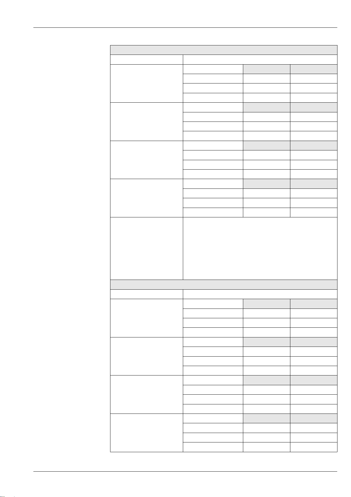
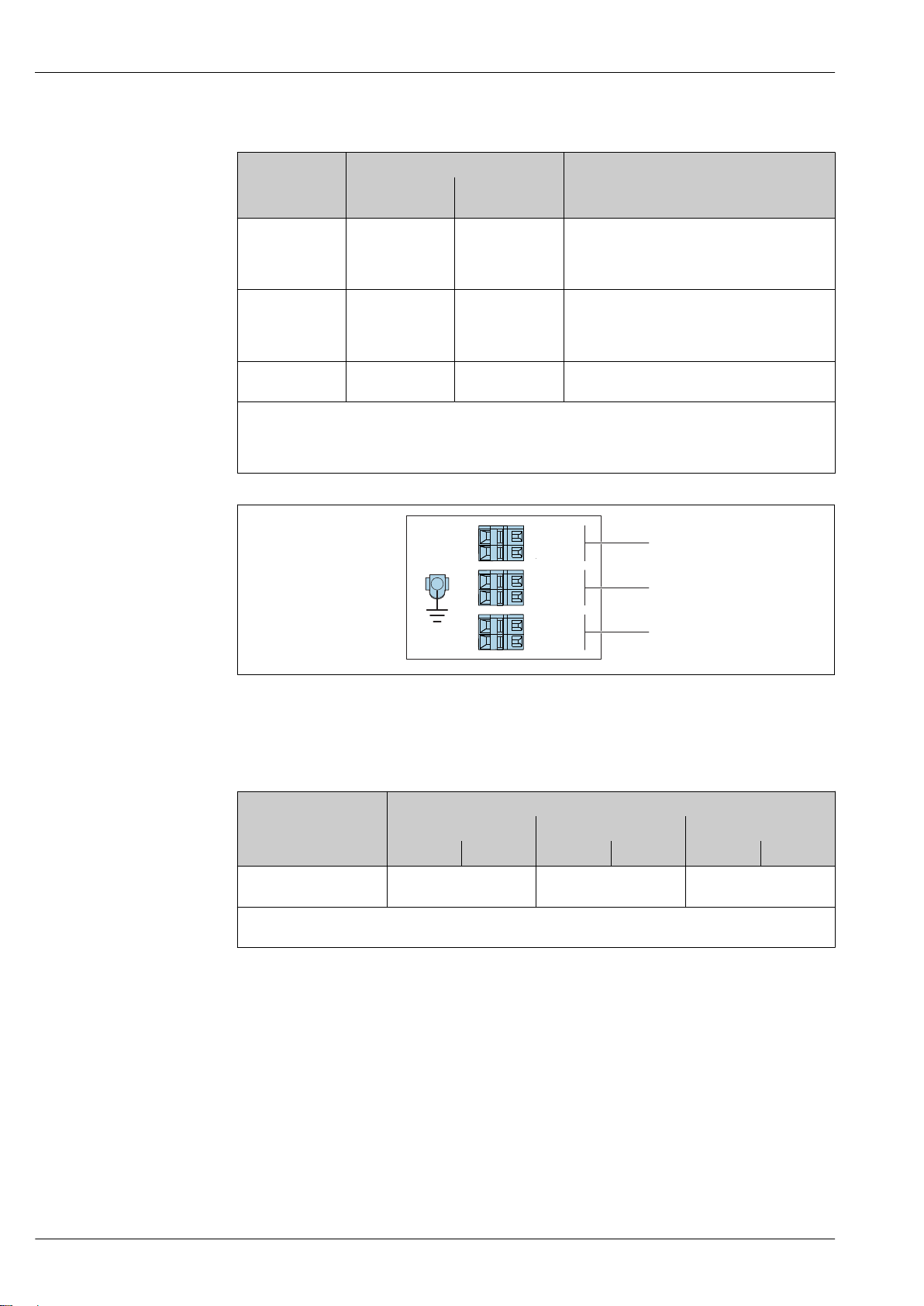
2 Terminal assignment 4-20 mA HART with pulse/frequency/switch output
Power supply: DC 24 V
1
2 Output 1: 4-20 mA HART (active)
3 Output 2: pulse/frequency/switch output (passive)
Terminal number
Order code
"Output"
Power supply Output 1 Output 2
2 (L-) 1 (L+) 27 (–) 26 (+) 25 (–) 24 (+)
Option B DC 24 V 4-20 mA HART (active) Pulse/frequency/switch
Order code for "Output":
Option B: 4-20 mA HART with pulse/frequency/switch output
A0016888
output (passive)
24 Endress+Hauser
Proline Promass E 100
L
L
26
27BA
1
2
+
_
1
2
Заказывайте на сайте: www.tinnova.ru/endress_hauser/ || Эл. почта: info@tinnova.ru
PROFIBUS DP connection version
For use in the non-hazardous area and Zone 2/Div. 2
Order code for "Output", option L
Depending on the housing version, the transmitters can be ordered with terminals or device plugs.
Order code
"Housing"
Options
A, B
Options
A, B
Options
A, B, C
Order code for "Housing":
• Option A: compact, coated aluminum
• Option B: compact, hygienic, stainless
• Option C ultra-compact, hygienic, stainless
Connection methods available
Output
Terminals Terminals • Option A: coupling M20x1
Device plugs
→ 31
Device plugs
→ 31
Power
supply
Terminals • Option L: plug M12x1 + thread NPT ½"
Device plugs
→ 31
Possible options for order code
"Electrical connection"
• Option B: thread M20x1
Option C: thread G ½"
•
• Option D: thread NPT ½"
• Option N: plug M12x1 + coupling M20
• Option P: plug M12x1 + thread G ½"
• Option U: plug M12x1 + thread M20
Option Q: 2 x plug M12x1
A0022716
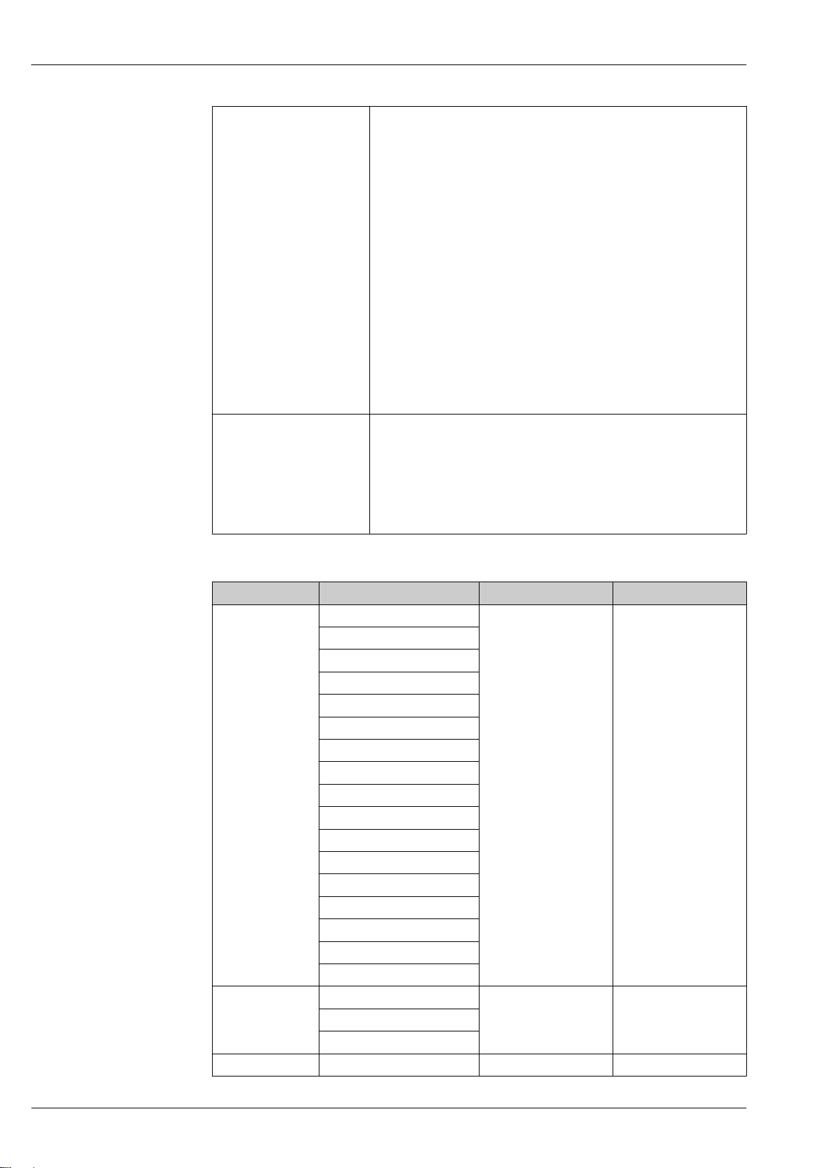
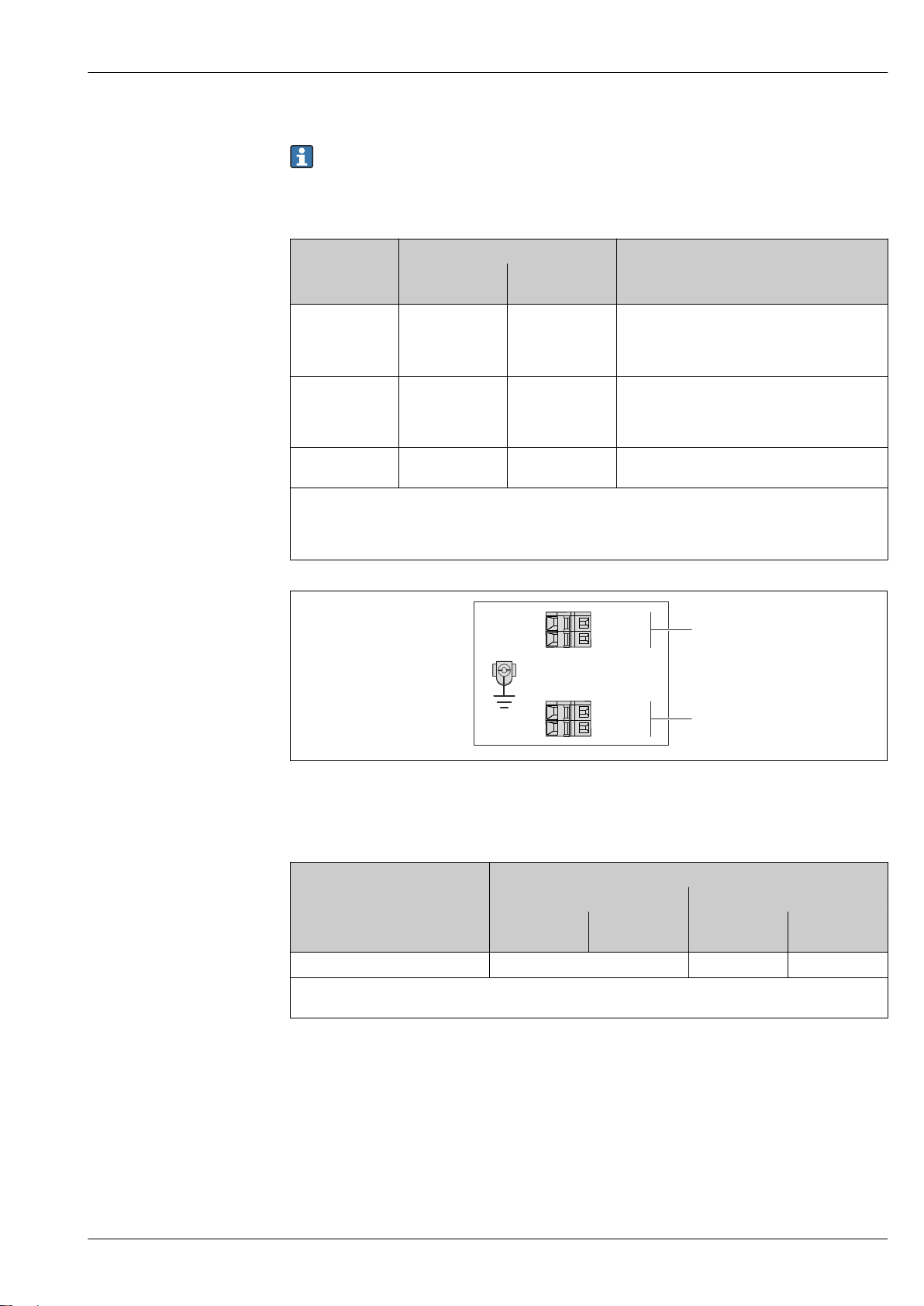
3 PROFIBUS DP terminal assignment
Power supply: DC 24 V
1
2 PROFIBUS DP
Terminal number
Order code
"Output"
Option L DC 24 V B A
Order code for "Output":
Option L: PROFIBUS DP, for use in non-hazardous areas and Zone 2/Div. 2
Power supply Output
2 (L-) 1 (L+) 26 (RxD/TxD-P) 27 (RxD/TxD-
N)
Endress+Hauser 25
Proline Promass E 100
L
L
26
27
A
B
1
2
+
_
1
2
Заказывайте на сайте: www.tinnova.ru/endress_hauser/ || Эл. почта: info@tinnova.ru
Modbus RS485 connection version
For use in the non-hazardous area and Zone 2/Div. 2
Order code for "Output", option M
Depending on the housing version, the transmitters can be ordered with terminals or device plugs.
Order code
"Housing"
Options
A, B
Options
A, B
Options
A, B, C
Order code for "Housing":
• Option A: compact, coated aluminum
• Option B: compact, hygienic, stainless
• Option C ultra-compact, hygienic, stainless
Connection methods available
Output
Terminals Terminals • Option A: coupling M20x1
Device plugs
→ 31
Device plugs
→ 31
Power
supply
Terminals • Option L: plug M12x1 + thread NPT ½"
Device plugs
→ 31
Possible options for order code
"Electrical connection"
• Option B: thread M20x1
Option C: thread G ½"
•
• Option D: thread NPT ½"
• Option N: plug M12x1 + coupling M20
• Option P: plug M12x1 + thread G ½"
• Option U: plug M12x1 + thread M20
Option Q: 2 x plug M12x1
A0019528
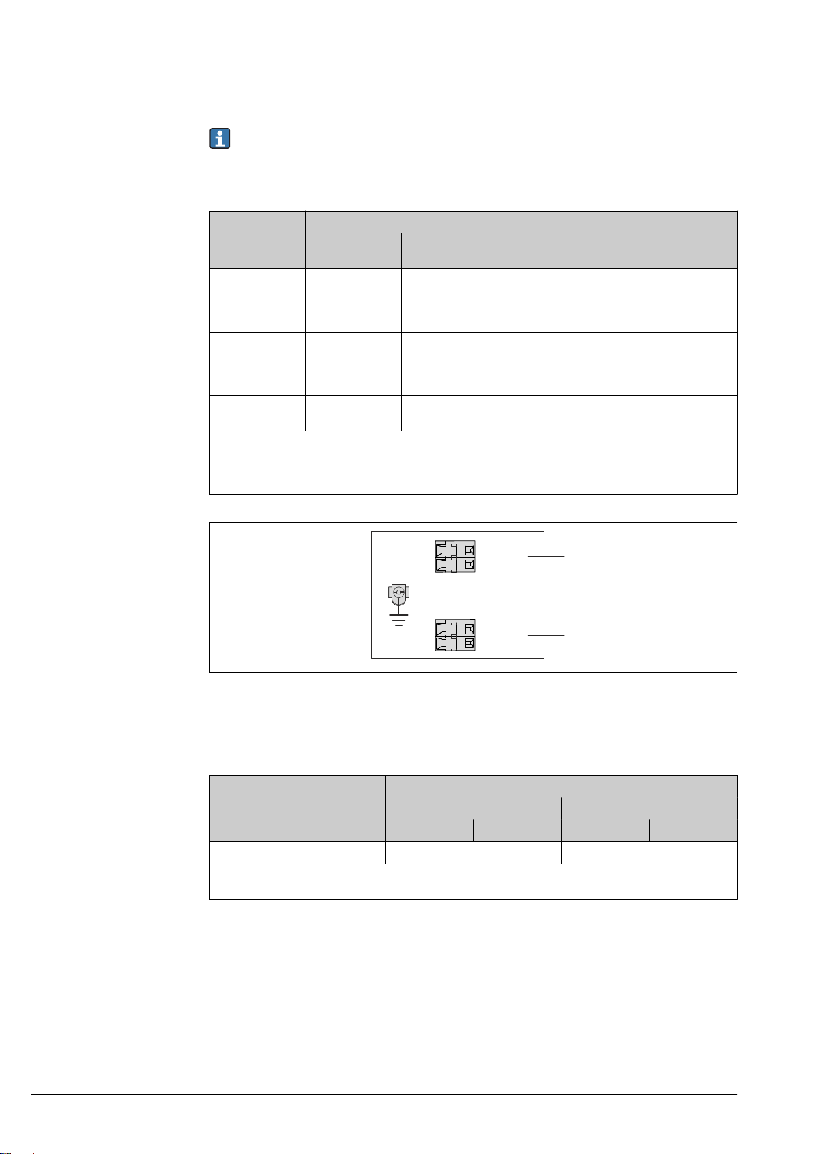
4 Modbus RS485 terminal assignment, connection version for use in non-hazardous areas and Zone 2/Div.
2
Power supply: DC 24 V
1
2 Modbus RS485
Terminal number
Order code
"Output"
Option M DC 24 V Modbus RS485
Order code for "Output":
Option M: Modbus RS485, for use in non-hazardous areas and Zone 2/Div. 2
Power supply Output
1 (L+) 2 (L-) 26 (B) 27 (A)
26 Endress+Hauser
Proline Promass E 100
L
L
62
72
A
B
10
20
+
_
1
2
Заказывайте на сайте: www.tinnova.ru/endress_hauser/ || Эл. почта: info@tinnova.ru
Modbus RS485 connection version
For use in the intrinsically safe area. Connection via Safety Barrier Promass 100.
Order code for "Output", option M
Depending on the housing version, the transmitters can be ordered with terminals or device plugs.
Order code
"Housing"
Options
A, B
A, B, C Device plugs
Order code for "Housing":
• Option A: compact, coated aluminum
• Option B: compact, hygienic, stainless
• Option C ultra-compact, hygienic, stainless
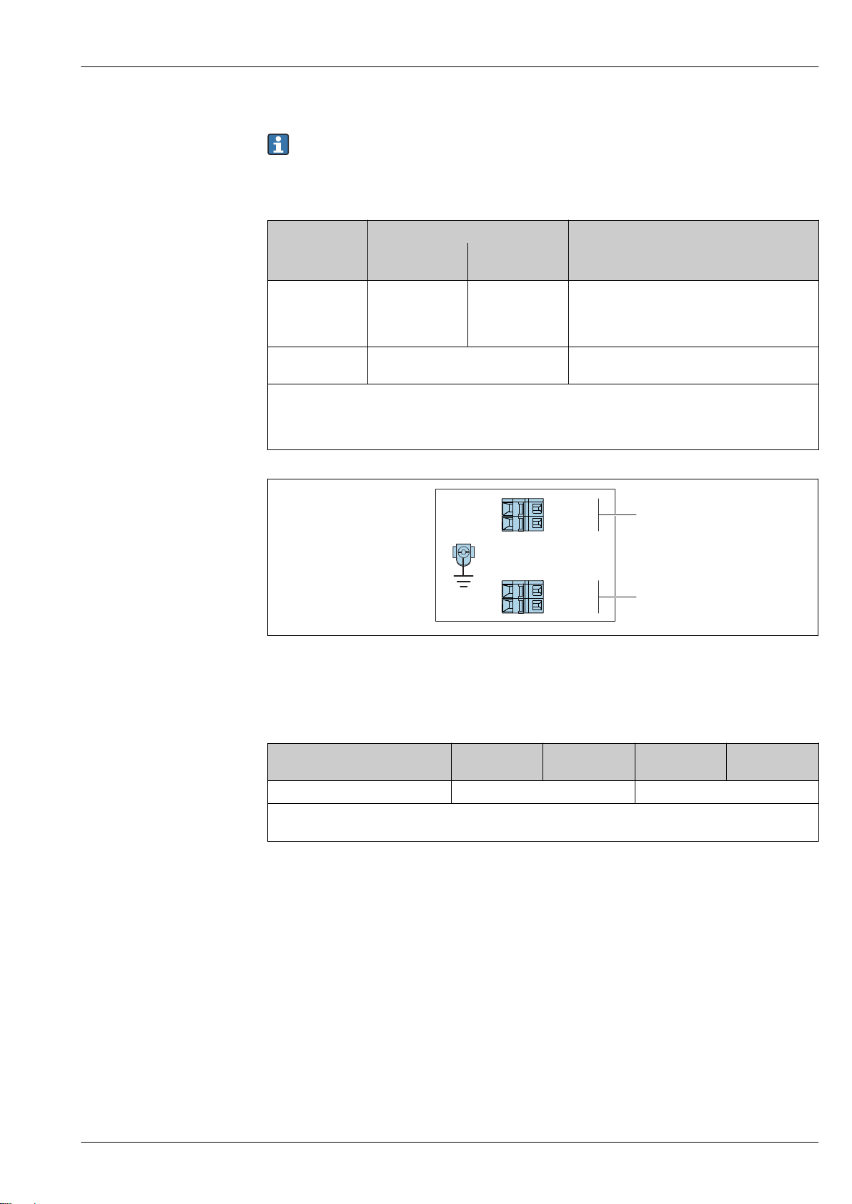
5 Modbus RS485 terminal assignment, connection version for use in intrinsically safe areas (connection via
Safety Barrier Promass 100)
Intrinsically safe power supply
1
2 Modbus RS485
Connection methods available
Output
Terminals Terminals • Option A: coupling M20x1
→ 31
Power
supply
Possible options for order code
"Electrical connection"
• Option B: thread M20x1
Option C: thread G ½"
•
• Option D: thread NPT ½"
Option I: plug M12x1
A0030219
Order code
"Output"
Option M Intrinsically safe supply voltage Modbus RS485 intrinsically safe
Order code for "Output":
Option M: Modbus RS485, for use in the intrinsically safe area (connection via Safety Barrier Promass 100)
Endress+Hauser 27
10 (L+) 20 (L-) 62 (B) 72 (A)
 Loading...