

Page 1
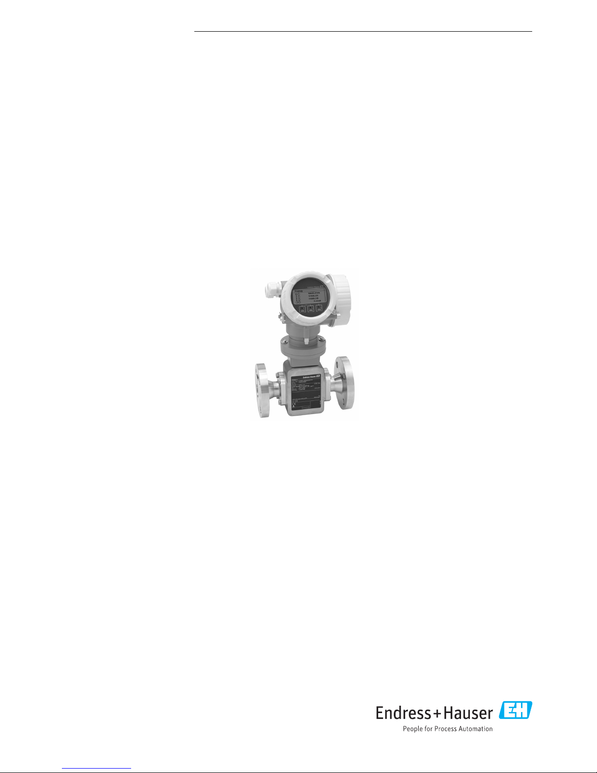
The measuring device for smallest flow rates with genuine two-wire
technology
Application
• The measuring principle is virtually independent of pressure,
density, temperature and viscosity
• For the smallest flow quantities and demanding hygienic
applications
Device properties
• Liner made of PFA
• Sensor housing made of stainless steel (3A, EHEDG)
• Wetted materials CIP, SIP cleanable
• Loop-powered technology
• Robust two-chamber housing
• Plant safety: worldwide approvals (SIL, Haz. area)
Your benefits
• Flexible installation concept – numerous hygienic process
connections
• Energy-saving flow measurement – no pressure loss due to
cross-section constriction
• Maintenance-free – no moving parts
• Convenient device wiring – separate connection
compartment
• Safe operation – no need to open the device due to display
with touch control, background lighting
• Integrated verification – Heartbeat Technology™
Products Solutions Services
Technical Information
Proline Promag H 200
Electromagnetic flowmeter
TI01061D/06/EN/05.17
71372370
Page 2

Proline Promag H 200
2 Endress+Hauser
Table of contents
Document information ....................... 3
Symbols used ................................ 3
Function and system design ................... 3
Measuring principle ............................ 3
Measuring system ............................. 5
Safety ..................................... 5
Input ..................................... 5
Measured variable ............................. 5
Measuring range .............................. 5
Operable flow range ........................... 6
Output ................................... 6
Output signal ................................ 6
Signal on alarm ............................... 7
Load ...................................... 9
Ex connection data ............................ 9
Low flow cut off ............................. 13
Galvanic isolation ............................ 13
Protocol-specific data .......................... 13
Power supply ............................. 17
Terminal assignment .......................... 17
Pin assignment, device plug ...................... 18
Supply voltage .............................. 18
Power consumption ........................... 18
Current consumption .......................... 19
Power supply failure .......................... 19
Electrical connection .......................... 19
Potential equalization ......................... 23
Terminals ................................. 24
Cable entries ............................... 24
Cable specification ............................ 24
Overvoltage protection ......................... 25
Performance characteristics .................. 25
Reference operating conditions ................... 25
Maximum measured error ....................... 25
Repeatability ............................... 26
Influence of ambient temperature ................. 26
Installation ............................... 26
Mounting location ............................ 27
Orientation ................................ 27
Inlet and outlet runs .......................... 28
Adapters .................................. 28
Special mounting instructions .................... 29
Environment .............................. 29
Ambient temperature range ..................... 29
Storage temperature .......................... 30
Degree of protection .......................... 30
Shock resistance ............................. 30
Vibration resistance ........................... 30
Mechanical load ............................. 30
Electromagnetic compatibility (EMC) ............... 30
Process .................................. 30
Medium temperature range ...................... 30
Conductivity ................................ 31
Pressure-temperature ratings .................... 31
Pressure tightness ............................ 34
Flow limit ................................. 34
Pressure loss ............................... 34
System pressure ............................. 35
Vibrations ................................. 35
Mechanical construction .................... 35
Dimensions in SI units ......................... 35
Dimensions in US units ......................... 48
Weight ................................... 57
Measuring tube specification ..................... 57
Materials .................................. 58
Fitted electrodes ............................. 59
Process connections ........................... 59
Surface roughness ............................ 59
Operability ............................... 60
Operating concept ............................ 60
Local operation .............................. 60
Remote operation ............................ 61
Service interface ............................. 63
Certificates and approvals ................... 64
CE mark ................................... 64
C-Tick symbol ............................... 64
Ex approval ................................ 64
Sanitary compatibility ......................... 65
Functional safety ............................. 65
HART certification ............................ 65
FOUNDATION Fieldbus certification ................ 65
Certification PROFIBUS ......................... 65
Other standards and guidelines ................... 65
Ordering information ....................... 66
Application packages ....................... 66
Diagnostics functions .......................... 66
Heartbeat Technology ......................... 66
Accessories ............................... 67
Device-specific accessories ...................... 67
Communication-specific accessories ................ 68
Service-specific accessories ...................... 68
System components ........................... 69
Documentation ............................ 69
Standard documentation ........................ 69
Supplementary device-dependent documentation ....... 70
Registered trademarks ...................... 70
Page 3
Proline Promag H 200
Endress+Hauser 3
Document information
Symbols used Electrical symbols
Symbol Meaning Symbol Meaning
Direct current Alternating current
Direct current and alternating current Ground connection
A grounded terminal which, as far as
the operator is concerned, is
grounded via a grounding system.
Protective ground connection
A terminal which must be connected
to ground prior to establishing any
other connections.
Equipotential connection
A connection that has to be connected
to the plant grounding system: This
may be a potential equalization line
or a star grounding system depending
on national or company codes of
practice.
Symbols for certain types of information
Symbol Meaning
Permitted
Procedures, processes or actions that are permitted.
Preferred
Procedures, processes or actions that are preferred.
Forbidden
Procedures, processes or actions that are forbidden.
Tip
Indicates additional information.
Reference to documentation
Reference to page
Reference to graphic
Visual inspection
Symbols in graphics
Symbol Meaning Symbol Meaning
1, 2, 3,... Item numbers
,…,
Series of steps
A, B, C, ... Views A-A, B-B, C-C, ... Sections
-
Hazardous area
.
Safe area (non-hazardous area)
Flow direction
Function and system design
Measuring principle
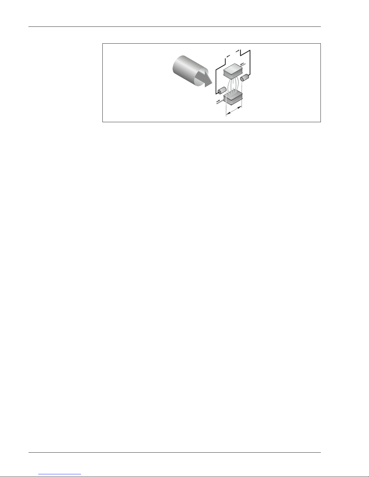
Following Faraday's law of magnetic induction, a voltage is induced in a conductor moving through a
magnetic field.
Page 4
Proline Promag H 200
4 Endress+Hauser
I
L
B
I
U
e
v
A0017035
Ue Induced voltage
B Magnetic induction (magnetic field)
L Electrode spacing
I Current
v Flow velocity
In the electromagnetic measuring principle, the flowing medium is the moving conductor. The
voltage induced (Ue) is proportional to the flow velocity (v) and is supplied to the amplifier by means
of two measuring electrodes. The flow volume (Q) is calculated via the pipe cross-section (A). The DC
magnetic field is created through a switched direct current of alternating polarity.
Formulae for calculation
• Induced voltage Ue = B · L · v
• Volume flow Q = A · v
Page 5
Proline Promag H 200
Endress+Hauser 5
Measuring system
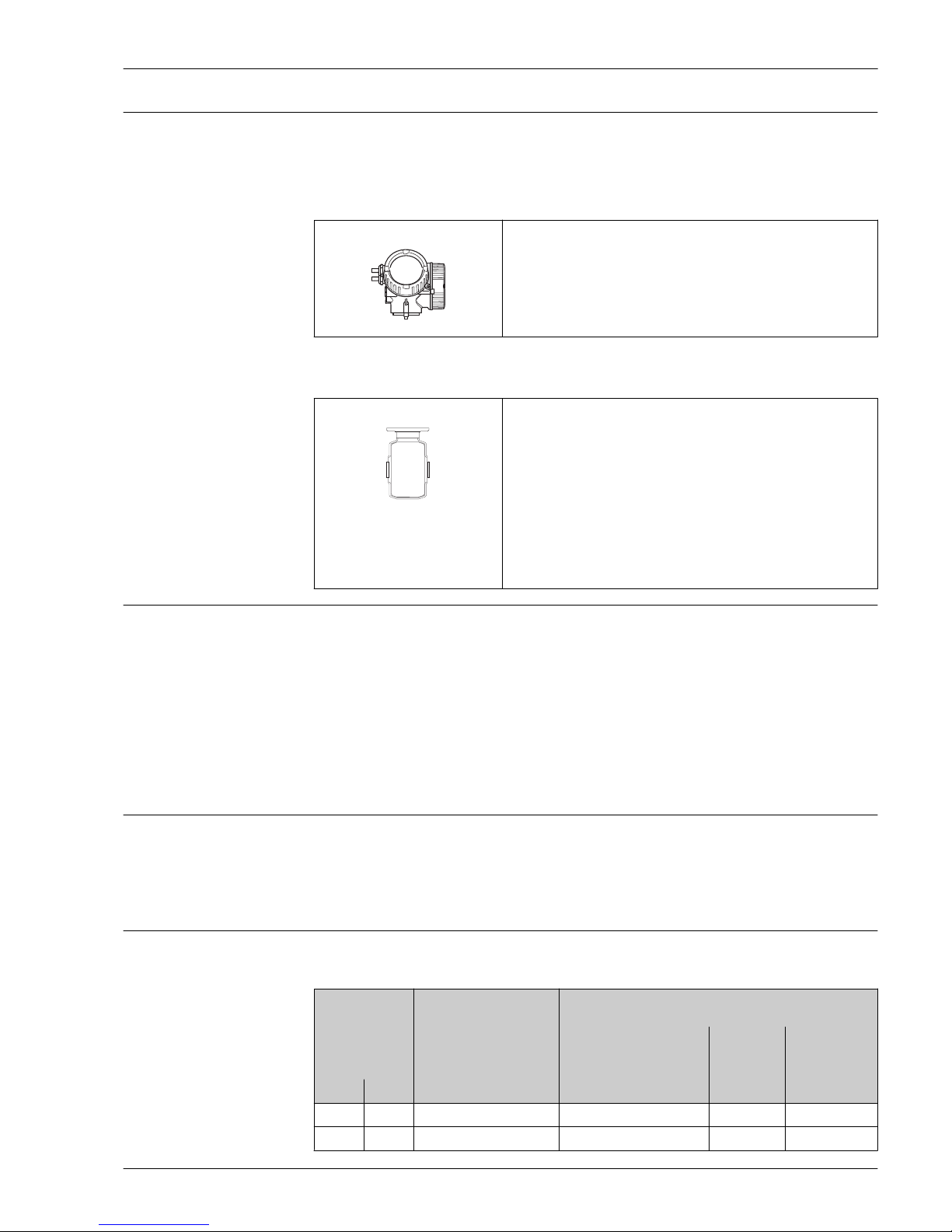
The device consists of a transmitter and a sensor.
The device is available as a compact version:
The transmitter and sensor form a mechanical unit.
Transmitter
Promag 200 Materials:
Aluminum, AlSi10Mg, coated
Configuration:
• External operation via four-line, illuminated local display with touch
control and guided menus ("Make-it-run" wizards) for applications
• Via operating tools (e.g. FieldCare)
A0013471
Sensor
Promag H Nominal diameter range: DN 2 to 25 (1/12 to 1")
Materials:
• Sensor housing: stainless steel 1.4301 (304)
• Measuring tubes: stainless steel, 1.4301 (304)
• Liner: PFA (USP Class VI; FDA 21 CFR 177.1550; 3A)
• Electrodes: stainless steel 1.4435 (F316L); Alloy C22, 2.4602 (UNS
N06022); tantalum; platinum
• Process connections: stainless steel, 1.4404 (F316L); PVDF; PVC
adhesive sleeve
• Seals: EPDM, FKM, Kalrez
• Grounding rings (only for DN 02 to 25 (1/12 to 1")): stainless steel,
1.4435 (F316L); Alloy C22, 2.4602 (UNS N06022); tantalum
A0017702
Safety IT security
We only provide a warranty if the device is installed and used as described in the Operating
Instructions. The device is equipped with security mechanisms to protect it against any inadvertent
changes to the device settings.
IT security measures in line with operators' security standards and designed to provide additional
protection for the device and device data transfer must be implemented by the operators themselves.
Input
Measured variable Direct measured variables
Volume flow (proportional to induced voltage)
Calculated measured variables
Mass flow
Measuring range
Typically v = 0.01 to 10 m/s (0.03 to 33 ft/s) with the specified accuracy
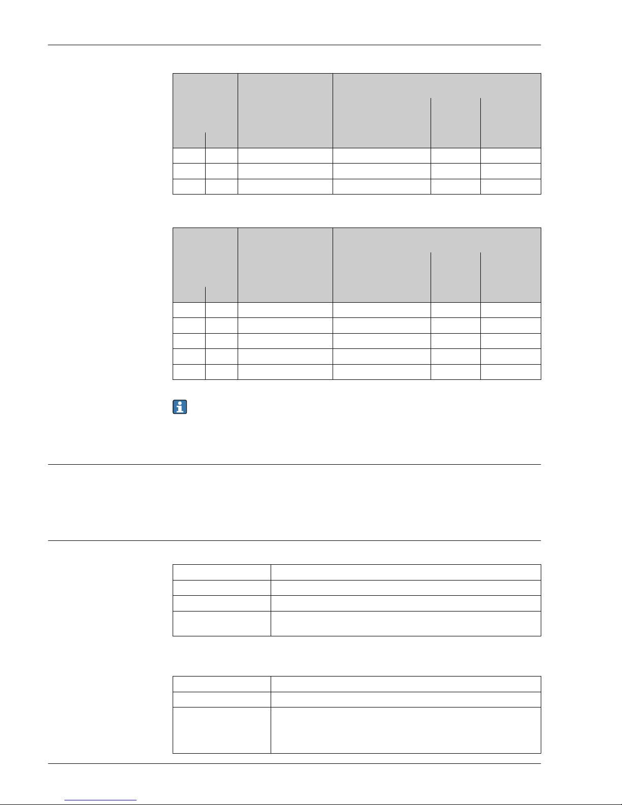
Flow characteristic values in SI units
Nominal
diameter
Recommended
flow
Factory settings
Min./max. full scale value
(v ~ 0.3/10 m/s)
Full scale value current
output
(v ~ 2.5 m/s)
Pulse value
(~ 2 pulse/s)
Low flow cut off
(v ~ 0.04 m/s)
[mm] [in] [dm3/min] [dm3/min] [dm3] [dm3/min]
2 1/12 0.06 to 1.8 0,5 0.005 0,01
4 1/8 0.25 to 7 2 0.025 0,05
Page 6
Proline Promag H 200
6 Endress+Hauser
Nominal
diameter
Recommended
flow
Factory settings
Min./max. full scale value
(v ~ 0.3/10 m/s)
Full scale value current
output
(v ~ 2.5 m/s)
Pulse value
(~ 2 pulse/s)
Low flow cut off
(v ~ 0.04 m/s)
[mm] [in] [dm3/min] [dm3/min] [dm3] [dm3/min]
8 3/8 1 to 30 8 0.1 0,1
15 ½ 4 to 100 25 0.2 0,5
25 1 9 to 300 75 0.5 1
Flow characteristic values in US units
Nominal
diameter
Recommended
flow
Factory settings
Min./max. full scale value
(v ~ 0.3/10 m/s)
Full scale value current
output
(v ~ 2.5 m/s)
Pulse value
(~ 2 pulse/s)
Low flow cut off
(v ~ 0.04 m/s)
[in] [mm] [gal/min] [gal/min] [gal] [gal/min]
1/12 2 0.015 to 0.5 0,1 0,001 0,002
1/8 4 0.07 to 2 0,5 0,005 0,008
3/8 8 0.25 to 8 2 0,02 0,025
½ 15 1 to 27 6 0,05 0,1
1 25 2.5 to 80 18 0,2 0,25
To calculate the measuring range, use the Applicator sizing tool → 68
Recommended measuring range
"Flow limit" section → 34
Operable flow range
Over 1000 : 1
Output
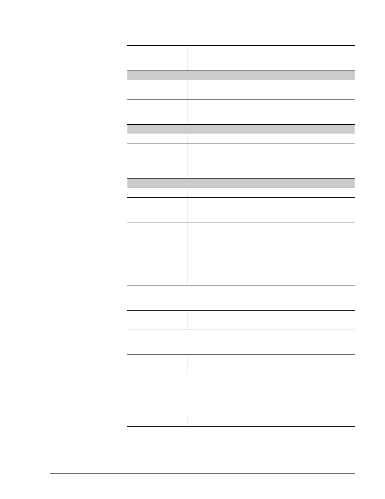
Output signal Current output
Current output 4-20 mA HART (passive)
Resolution < 1 µA
Damping Adjustable: 0.0 to 999.9 s
Assignable measured
variables
• Volume flow
• Mass flow
Pulse/frequency/switch output
Function Can be set to pulse, frequency or switch output
Version Passive, open collector
Maximum input values • DC 35 V
• 50 mA
For information on the Ex connection values → 9
Page 7
Proline Promag H 200
Endress+Hauser 7
Voltage drop • For ≤ 2 mA: 2 V
• For 10 mA: 8 V
Residual current ≤ 0.05 mA
Pulse output
Pulse width Adjustable: 5 to 2 000 ms
Maximum pulse rate 100 Impulse/s
Pulse value Adjustable
Assignable measured
variables
• Volume flow
• Mass flow
Frequency output
Output frequency Adjustable: 0 to 1 000 Hz
Damping Adjustable: 0 to 999 s
Pulse/pause ratio 1:1
Assignable measured
variables
• Volume flow
• Mass flow
Switch output
Switching behavior Binary, conductive or non-conductive
Switching delay Adjustable: 0 to 100 s
Number of switching
cycles
Unlimited
Assignable functions • Off
• On
• Diagnostic behavior
• Limit value
– Volume flow
– Mass flow
• Flow direction monitoring
• Status
– Empty pipe detection
– Low flow cut off
FOUNDATION Fieldbus
Signal encoding Manchester Bus Powered (MBP)
Data transfer 31.25 KBit/s, Voltage mode
PROFIBUS PA
Signal encoding Manchester Bus Powered (MBP)
Data transfer 31.25 KBit/s, Voltage mode
Signal on alarm
Depending on the interface, failure information is displayed as follows:
Current output
HART
Device diagnostics Device condition can be read out via HART Command 48
Page 8
Proline Promag H 200
8 Endress+Hauser
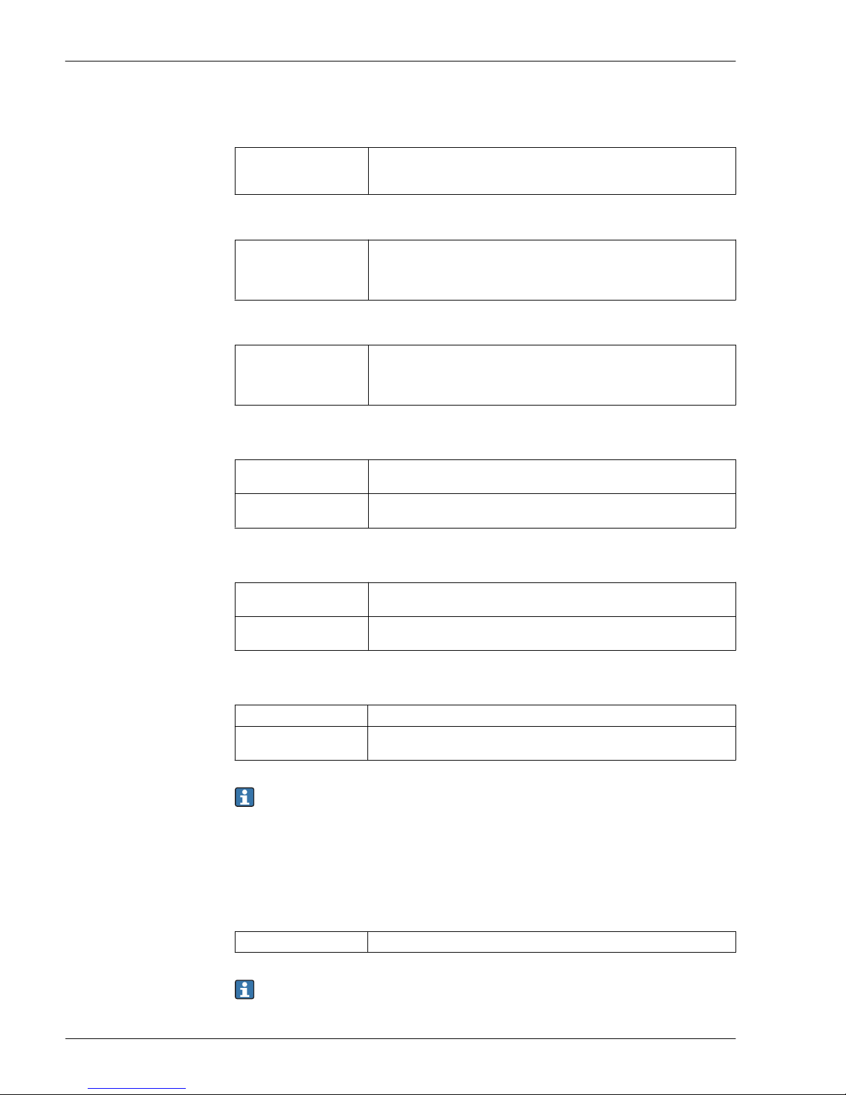
Pulse/frequency/switch output
Pulse output
Failure mode Choose from:
• Actual value
• No pulses
Frequency output
Failure mode Choose from:
• Actual value
• 0 Hz
• Defined value: 0 to 1 250 Hz
Switch output
Failure mode Choose from:
• Current status
• Open
• Closed
FOUNDATION Fieldbus
Status and alarm
messages
Diagnostics in accordance with FF-912
Error current FDE (Fault
Disconnection Electronic)
0 mA
PROFIBUS PA
Status and alarm
messages
Diagnostics in accordance with PROFIBUS PA Profile 3.02
Error current FDE (Fault
Disconnection Electronic)
0 mA
Local display
Plain text display With information on cause and remedial measures
Backlight Additionally for device version with SD03 local display: red lighting indicates a
device error.
Status signal as per NAMUR recommendation NE 107
Operating tool
• Via digital communication:
– HART protocol
– FOUNDATION Fieldbus
– PROFIBUS PA
• Via service interface
Plain text display With information on cause and remedial measures
Additional information on remote operation → 61
Page 9
Proline Promag H 200
Endress+Hauser 9
Load
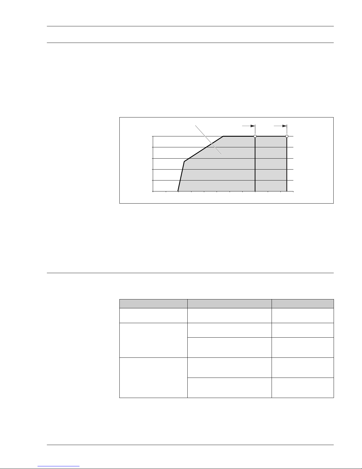
Load for current output: 0 to 500 Ω, depending on the external supply voltage of the power supply
unit
Calculation of the maximum load
Depending on the supply voltage of the power supply unit (US), the maximum load (RB) including
line resistance must be observed to ensure adequate terminal voltage at the device. In doing so,
observe the minimum terminal voltage
• For US = 18 to 18.9 V: RB ≤ (US - 18 V): 0.0036 A
• For US = 18.9 to 24.5 V: RB ≤ (US - 13.5 V): 0.022 A
• For US = 24.5 to 30 V: RB ≤ 500 Ω
0
100
200
300
400
500
14
16 18 20
22 24
26 28 30 32
U [V]
s
R [ ]bW
1.1 1.21
34 36
A0013563
1 Operating range
1.1 For order code for "Output", option A "4-20 mA HART"/option B "4-20 mA HART, pulse/frequency/switch
output" with Ex i
1.2 For order code for "Output", option A "4-20 mA HART"/option B "4-20 mA HART, pulse/frequency/switch
output" with non-Ex and Ex d
Sample calculation
Supply voltage of the power supply unit: US = 19 V
Maximum load: RB ≤ (19 V - 13.5 V): 0.022 A = 250 Ω
Ex connection data Safety-related values
Type of protection Ex d
Order code for "Output" Output type Safety-related values
Option A 4-20mA HART U
nom
= DC 35 V
U
max
= 250 V
Option B 4-20mA HART U
nom
= DC 35 V
U
max
= 250 V
Pulse/frequency/switch output U
nom
= DC 35 V
U
max
= 250 V
P
max
= 1 W
1)
Option E FOUNDATION Fieldbus U
nom
= DC 32 V
U
max
= 250 V
P
max
= 0.88 W
Pulse/frequency/switch output U
nom
= DC 35 V
U
max
= 250 V
P
max
= 1 W
1)
Page 10
Proline Promag H 200
10 Endress+Hauser
Order code for "Output" Output type Safety-related values
Option G PROFIBUS PA U
nom
= DC 32 V
U
max
= 250 V
P
max
= 0.88 W
Pulse/frequency/switch output U
nom
= DC 35 V
U
max
= 250 V
P
max
= 1 W
1)
1) Internal circuit limited by Ri = 760.5 Ω
Ex nA type of protection
Order code for "Output" Output type Safety-related values
Option A 4-20mA HART U
nom
= DC 35 V
U
max
= 250 V
Option B 4-20mA HART U
nom
= DC 35 V
U
max
= 250 V
Pulse/frequency/switch output U
nom
= DC 35 V
U
max
= 250 V
P
max
= 1 W
1)
Option E FOUNDATION Fieldbus U
nom
= DC 32 V
U
max
= 250 V
P
max
= 0.88 W
Pulse/frequency/switch output U
nom
= DC 35 V
U
max
= 250 V
P
max
= 1 W
1)
Option G PROFIBUS PA U
nom
= DC 32 V
U
max
= 250 V
P
max
= 0.88 W
Pulse/frequency/switch output U
nom
= DC 35 V
U
max
= 250 V
P
max
= 1 W
1)
1) Internal circuit limited by Ri = 760.5 Ω
Type of protection XP
Order code for "Output" Output type Safety-related values
Option A 4-20mA HART U
nom
= DC 35 V
U
max
= 250 V
Option B 4-20mA HART U
nom
= DC 35 V
U
max
= 250 V
Pulse/frequency/switch output U
nom
= DC 35 V
U
max
= 250 V
P
max
= 1 W
1)
Option E FOUNDATION Fieldbus U
nom
= DC 32 V
U
max
= 250 V
P
max
= 0.88 W
Pulse/frequency/switch output U
nom
= DC 35 V
U
max
= 250 V
P
max
= 1 W
1)
Page 11
Proline Promag H 200
Endress+Hauser 11
Order code for "Output" Output type Safety-related values
Option G PROFIBUS PA U
nom
= DC 32 V
U
max
= 250 V
P
max
= 0.88 W
Pulse/frequency/switch output U
nom
= DC 35 V
U
max
= 250 V
P
max
= 1 W
1)
1) Internal circuit limited by Ri = 760.5 Ω
Intrinsically safe values
Type of protection Ex ia
Order code for "Output" Output type Intrinsically safe values
Option A 4-20mA HART Ui = DC 30 V
Ii = 300 mA
Pi = 1 W
Li = 0 μH
Ci = 5 nF
Option B 4-20mA HART Ui = DC 30 V
Ii = 300 mA
Pi = 1 W
Li = 0 μH
Ci = 5 nF
Pulse/frequency/switch output Ui = DC 30 V
Ii = 300 mA
Pi = 1 W
Li = 0 μH
Ci = 6 nF
Option E FOUNDATION Fieldbus STANDARD
Ui = 30 V
li = 300 mA
Pi = 1.2 W
Li = 10 µH
Ci = 5 nF
FISCO
Ui = 17.5 V
li = 550 mA
Pi = 5.5 W
Li = 10 µH
Ci = 5 nF
Pulse/frequency/switch output Ui = 30 V
li = 300 mA
Pi = 1 W
Li = 0 µH
Ci = 6 nF
Option G PROFIBUS PA STANDARD
Ui = 30 V
li = 300 mA
Pi = 1.2 W
Li = 10 µH
Ci = 5 nF
FISCO
Ui = 17.5 V
li = 550 mA
Pi = 5.5 W
Li = 10 µH
Ci = 5 nF
Pulse/frequency/switch output Ui = 30 V
li = 300 mA
Pi = 1 W
Li = 0 µH
Ci = 6 nF
Page 12
Proline Promag H 200
12 Endress+Hauser
Type of protection Ex ic
Order code for "Output" Output type Intrinsically safe values
Option A 4-20mA HART Ui = DC 35 V
Ii = n.a.
Pi = 1 W
Li = 0 μH
Ci = 5 nF
Option B 4-20mA HART Ui = DC 35 V
Ii = n.a.
Pi = 1 W
Li = 0 μH
Ci = 5 nF
Pulse/frequency/switch output Ui = DC 35 V
Ii = n.a.
Pi = 1 W
Li = 0 μH
Ci = 6 nF
Option E FOUNDATION Fieldbus STANDARD
Ui = 32 V
li = 300 mA
Pi = n.a.
Li = 10 µH
Ci = 5 nF
FISCO
Ui = 17.5 V
li = n.a.
Pi = n.a.
Li = 10 µH
Ci = 5 nF
Pulse/frequency/switch output Ui = 35 V
li = 300 mA
Pi = 1 W
Li = 0 µH
Ci = 6 nF
Option G PROFIBUS PA STANDARD
Ui = 32 V
li = 300 mA
Pi = n.a.
Li = 10 µH
Ci = 5 nF
FISCO
Ui = 17.5 V
li = n.a.
Pi = n.a.
Li = 10 µH
Ci = 5 nF
Pulse/frequency/switch output Ui = 35 V
li = 300 mA
Pi = 1 W
Li = 0 µH
Ci = 6 nF
Type of protection IS
Order code for "Output" Output type Intrinsically safe values
Option A 4-20mA HART Ui = DC 30 V
Ii = 300 mA
Pi = 1 W
Li = 0 μH
Ci = 5 nF
Option B 4-20mA HART Ui = DC 30 V
Ii = 300 mA
Pi = 1 W
Li = 0 μH
Ci = 5 nF
Pulse/frequency/switch output Ui = DC 30 V
Ii = 300 mA
Pi = 1 W
Li = 0 μH
Ci = 6 nF
Page 13
Proline Promag H 200
Endress+Hauser 13
Order code for "Output" Output type Intrinsically safe values
Option E FOUNDATION Fieldbus STANDARD
Ui = 30 V
li = 300 mA
Pi = 1.2 W
Li = 10 µH
Ci = 5 nF
FISCO
Ui = 17.5 V
li = 550 mA
Pi = 5.5 W
Li = 10 µH
Ci = 5 nF
Pulse/frequency/switch output Ui = 30 V
li = 300 mA
Pi = 1 W
Li = 0 µH
Ci = 6 nF
Option G PROFIBUS PA STANDARD
Ui = 30 V
li = 300 mA
Pi = 1.2 W
Li = 10 µH
Ci = 5 nF
FISCO
Ui = 17.5 V
li = 550 mA
Pi = 5.5 W
Li = 10 µH
Ci = 5 nF
Pulse/frequency/switch output Ui = 30 V
li = 300 mA
Pi = 1 W
Li = 0 µH
Ci = 6 nF
Low flow cut off
The switch points for low flow cut off are user-selectable.
Galvanic isolation
All outputs are galvanically isolated from one another.
Protocol-specific data HART
Manufacturer ID 0x11
Device type ID 0x48
HART protocol revision 7
Device description files
(DTM, DD)
Information and files under:
www.endress.com
HART load • Min. 250 Ω
• Max. 500 Ω
Dynamic variables Read out the dynamic variables: HART command 3
The measured variables can be freely assigned to the dynamic variables.
Measured variables for PV (primary dynamic variable)
• Off
• Volume flow
• Mass flow
Measured variables for SV, TV, QV (secondary, tertiary and quaternary
dynamic variable)
• Volume flow
• Mass flow
• Totalizer 1
• Totalizer 2
• Totalizer 3
Device variables Read out the device variables: HART command 9
The device variables are permanently assigned.
FOUNDATION Fieldbus
Manufacturer ID 0x452B48
Ident number 0x1048
Device revision 1
Page 14
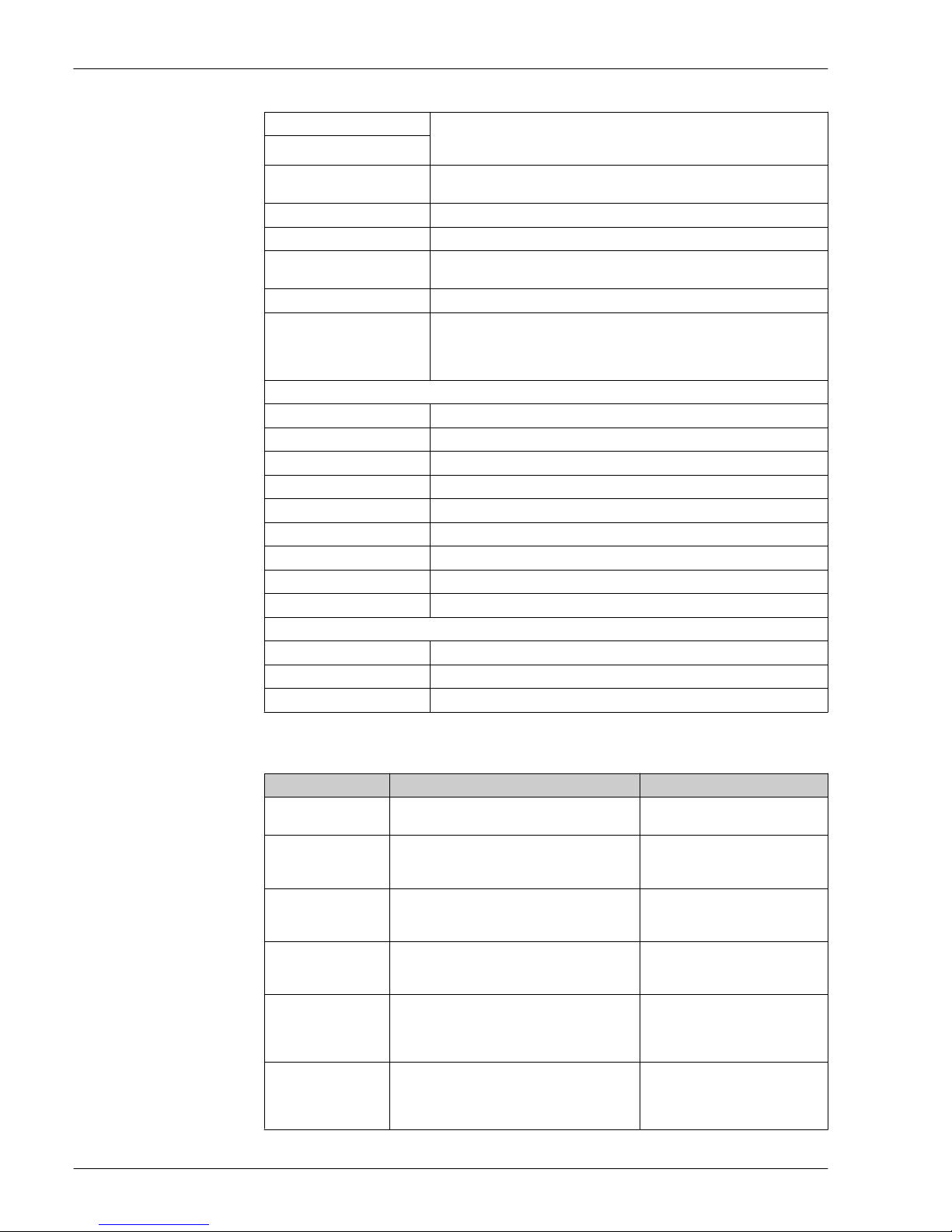
Proline Promag H 200
14 Endress+Hauser
DD revision Information and files under:
• www.endress.com
• www.fieldbus.org
CFF revision
Device Tester Version (ITK
version)
6.1.1
ITK Test Campaign Number IT094200
Link Master capability (LAS) Yes
Choice of "Link Master" and
"Basic Device"
Yes
Factory setting: Basic Device
Node address Factory setting: 247 (0xF7)
Supported functions The following methods are supported:
• Restart
• ENP Restart
• Diagnostic
Virtual Communication Relationships (VCRs)
Number of VCRs 44
Number of link objects in VFD 50
Permanent entries 1
Client VCRs 0
Server VCRs 10
Source VCRs 43
Sink VCRs 0
Subscriber VCRs 43
Publisher VCRs 43
Device Link Capabilities
Slot time 4
Min. delay between PDU 8
Max. response delay Min. 5
Transducer Blocks
Block Contents Output values
Setup Transducer Block
(TRDSUP)
All parameters for standard commissioning. No output values
Advanced Setup
Transducer Block
(TRDASUP)
All parameters for more accurate measurement
configuration.
No output values
Display Transducer
Block
(TRDDISP)
Parameters for configuring the local display. No output values
HistoROM Transducer
Block
(TRDHROM)
Parameters for using the HistoROM function. No output values
Diagnostic Transducer
Block
(TRDDIAG)
Diagnostics information. Process variables (AI Channel)
• Temperature (7)
• Volume flow (9)
• Mass flow (11)
Expert Configuration
Transducer Block
(TRDEXP)
Parameters that require the user to have indepth knowledge of the operation of the device
in order to configure the parameters
appropriately.
No output values
Page 15
Proline Promag H 200
Endress+Hauser 15
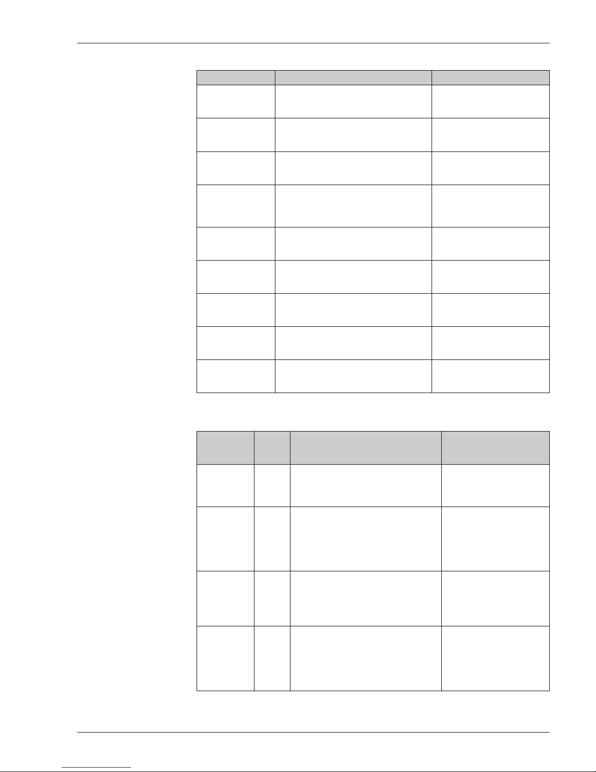
Block Contents Output values
Expert Information
Transducer Block
(TRDEXPIN)
Parameters that provide information about the
state of the device.
No output values
Service Sensor
Transducer Block
(TRDSRVS)
Parameters that can only be accessed by Endress
+Hauser Service.
No output values
Service Information
Transducer Block
(TRDSRVIF)
Parameters that provide Endress+Hauser Service
with information about the state of the device.
No output values
Total Inventory
Counter Transducer
Block
(TRDTIC)
Parameters for configuring all the totalizers and
the inventory counter.
Process variables (AI Channel)
• Totalizer 1 (16)
• Totalizer 2 (17)
• Totalizer 3 (18)
Heartbeat Technology
Transducer Block
(TRDHBT)
Parameters for the configuration and
comprehensive information about the results of
the verification.
No output values
Heartbeat Results 1
Transducer Block
(TRDHBTR1)
Information about the results of the verification. No output values
Heartbeat Results 2
Transducer Block
(TRDHBTR2)
Information about the results of the verification. No output values
Heartbeat Results 3
Transducer Block
(TRDHBTR3)
Information about the results of the verification. No output values
Heartbeat Results 4
Transducer Block
(TRDHBTR4)
Information about the results of the verification. No output values
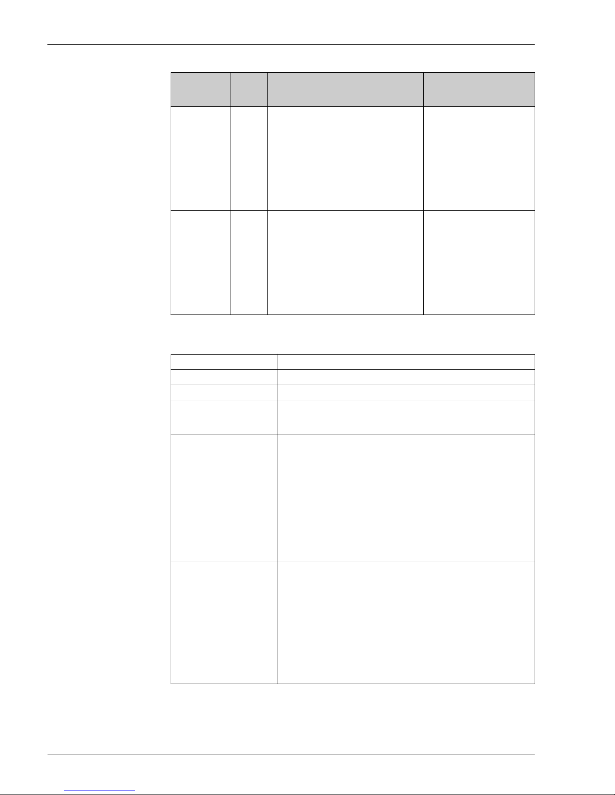
Function blocks
Block Number
of
blocks
Contents Process variables (Channel)
Resource Block
(RB)
1 This Block (extended functionality) contains
all the data that uniquely identify the device; it
is the equivalent of an electronic nameplate
for the device.
–
Analog Input
Block
(AI)
4 This Block (extended functionality) receives
the measurement data provided by the Sensor
Block (can be selected via a channel number)
and makes the data available for other blocks
at the output.
Execution time: 25 ms
Process variables (AI Channel)
• Temperature (7)
• Volume flow (9)
• Mass flow (11)
Discrete Input
Block
(DI)
2 This Block (standard functionality) receives a
discrete value (e.g. indicator that measuring
range has been exceeded) and makes the
value available for other blocks at the output.
Execution time: 19 ms
• Switch output state (101)
• Empty pipe detection (102)
• Low flow cut off (103)
• Status verification (105)
PID Block
(PID)
1 This Block (standard functionality) acts as a
proportional-integral-differential controller
and can be used universally for control in the
field. It enables cascading and feedforward
control.
Execution time: 25 ms
–
Page 16
Proline Promag H 200
16 Endress+Hauser
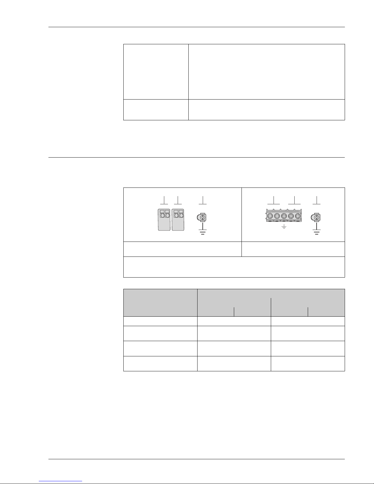
Block Number
of
blocks
Contents Process variables (Channel)
Multiple Digital
Output Block
(MDO)
1 This Block (standard functionality) receives
several discrete values and makes them
available for other blocks at the output.
Execution time: 19 ms
Channel_DO (122)
• Value 1: Reset totalizer 1
• Value 2: Reset totalizer 2
• Value 3: Reset totalizer 3
• Value 4: Flow override
• Value 5: Start heartbeat
verification
• Value 6: Status switch output
• Value 7: Not assigned
• Value 8: Not assigned
Integrator Block
(IT)
1 This Block (standard functionality) integrates
a measured variable over time or totalizes the
pulses from a Pulse Input Block. The Block can
be used as a totalizer that totalizes until a
reset, or as a batch totalizer whereby the
integrated value is compared against a target
value generated before or during the control
routine and generates a binary signal when
the target value is reached.
Execution time: 21 ms
–
PROFIBUS PA
Manufacturer ID 0x11
Ident number 0x1563
Profile version 3.02
Device description files (GSD,
DTM, DD)
Information and files under:
• www.endress.com
• www.profibus.org
Output values
(from measuring device to
automation system)
Analog input 1 to 2
• Mass flow
• Volume flow
Digital input 1 to 2
• Empty pipe detection
• Low flow cut off
• Status switch output
• Status verification
Totalizer 1 to 3
• Mass flow
• Volume flow
• Corrected volume flow
Input values
(from automation system to
measuring device)
Digital output 1 to 3 (fixed assignment)
• Digital output 1: switch positive zero return on/off
• Digital output 2: switch switch output on/off
• Digital output 3: start verification
Totalizer 1 to 3
• Totalize
• Reset and hold
• Preset and hold
• Operating mode configuration:
– Net flow total
– Forward flow total
– Reverse flow total
Page 17
Proline Promag H 200
Endress+Hauser 17
Supported functions • Identification & Maintenance
Simplest device identification on the part of the control system and
nameplate
• PROFIBUS upload/download
Reading and writing parameters is up to ten times faster with PROFIBUS
upload/download
• Condensed status
Simplest and self-explanatory diagnostic information by categorizing
diagnostic messages that occur
Configuration of the device
address
• DIP switches on the I/O electronics module
• Local display
• via operating tools (e.g. FieldCare)
Power supply
Terminal assignment Transmitter
Connection versions
–
4
+
1
–
2
+
3
1
2
3
A0013570
+
1
–
2
–
4
+
3
1
2
3
A0018161
Maximum number of terminals, without integrated
overvoltage protection
Maximum number of terminals, with integrated
overvoltage protection
1
2
3
Output 1 (passive): supply voltage and signal transmission
Output 2 (passive): supply voltage and signal transmission
Ground terminal for cable shield
Order code for "Output" Terminal numbers
Output 1 Output 2
1 (+) 2 (-) 3 (+) 4 (-)
Option A 4-20 mA HART (passive) -
Option B
1)
4-20 mA HART (passive) Pulse/frequency/switch output
(passive)
Option E
1) 2)
FOUNDATION Fieldbus
Pulse/frequency/switch output
(passive)
Option G
1) 3)
PROFIBUS PA
Pulse/frequency/switch output
(passive)
1) Output 1 must always be used; output 2 is optional.
2) FOUNDATION Fieldbus with integrated reverse polarity protection.
3) PROFIBUS PA with integrated reverse polarity protection.
Page 18
Proline Promag H 200
18 Endress+Hauser
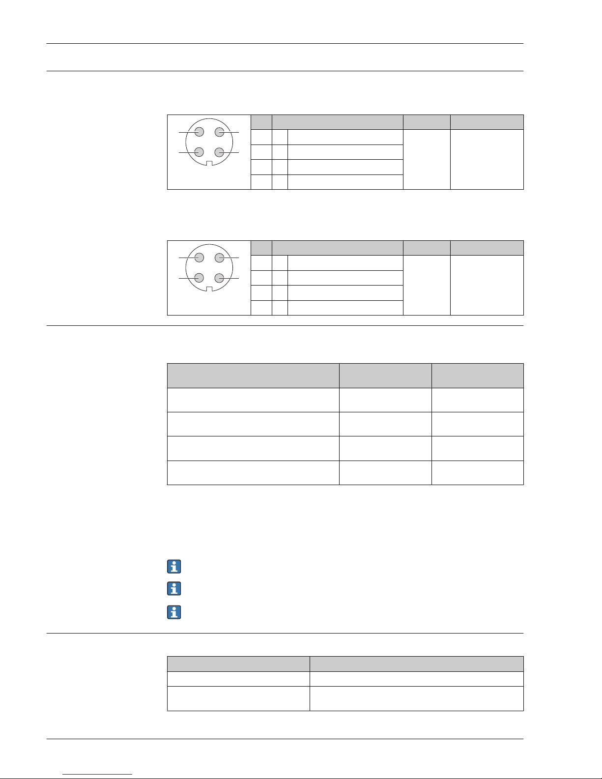
Pin assignment, device plug PROFIBUS PA
Device plug for signal transmission (device side)
1
2
4
3
A0019021
Pin Assignment Coding Plug/socket
1 + PROFIBUS PA + A Plug
2 Grounding
3 - PROFIBUS PA –
4 Not assigned
FOUNDATION Fieldbus
Device plug for signal transmission (device side)
1
2
4
3
A0019021
Pin Assignment Coding Plug/socket
1 + Signal + A Plug
2 - Signal –
3 Not assigned
4 Grounding
Supply voltage Transmitter
An external power supply is required for each output.
Order code for "Output"
Minimum
terminal voltage
Maximum
terminal voltage
Option A
1) 2)
: 4-20 mA HART • For 4 mA: ≥ DC 18 V
• For 20 mA: ≥ DC 14 V
DC 35 V
Option B
1) 2)
: 4-20 mA HART, pulse/frequency/
switch output
• For 4 mA: ≥ DC 18 V
• For 20 mA: ≥ DC 14 V
DC 35 V
Option E
3)
: FOUNDATION Fieldbus, pulse/
frequency/switch output
≥ DC 9 V
DC 32 V
Option G
3)
: PROFIBUS PA, pulse/frequency/switch
output
≥ DC 9 V
DC 32 V
1) External supply voltage of the power supply unit with load.
2) For device versions with SD03 local display: The terminal voltage must be increased by DC 2 V if
backlighting is used.
3) For device version with SD03 local display: The terminal voltage must be increased by DC 0.5 V if
backlighting is used.
For information about the load see → 9
Various power supply units can be ordered from Endress+Hauser: see "Accessories" section
→ 69
For information on the Ex connection values → 9
Power consumption Transmitter
Order code for "Output" Maximum power consumption
Option A: 4-20 mA HART 770 mW
Option B: 4-20 mA HART, pulse/
frequency/switch output
• Operation with output 1: 770 mW
• Operation with output 1 and 2: 2 770 mW
Page 19
Proline Promag H 200
Endress+Hauser 19
Order code for "Output" Maximum power consumption
Option E: FOUNDATION Fieldbus, pulse/
frequency/switch output
• Operation with output 1: 576 mW
• Operation with output 1 and 2: 2 576 mW
Option G: PROFIBUS PA, pulse/frequency/
switch output
• Operation with output 1: 512 mW
• Operation with output 1 and 2: 2 512 mW
For information on the Ex connection values → 9
Current consumption Current output
For every 4-20 mA or 4-20 mA HART current output: 3.6 to 22.5 mA
If the option Defined value is selected in the Failure mode parameter : 3.59 to 22.5 mA
PROFIBUS PA
16 mA
FOUNDATION Fieldbus
16 mA
Power supply failure
• Totalizers stop at the last value measured.
• Configuration is retained in the device memory (HistoROM).
• Error messages (incl. total operated hours) are stored.
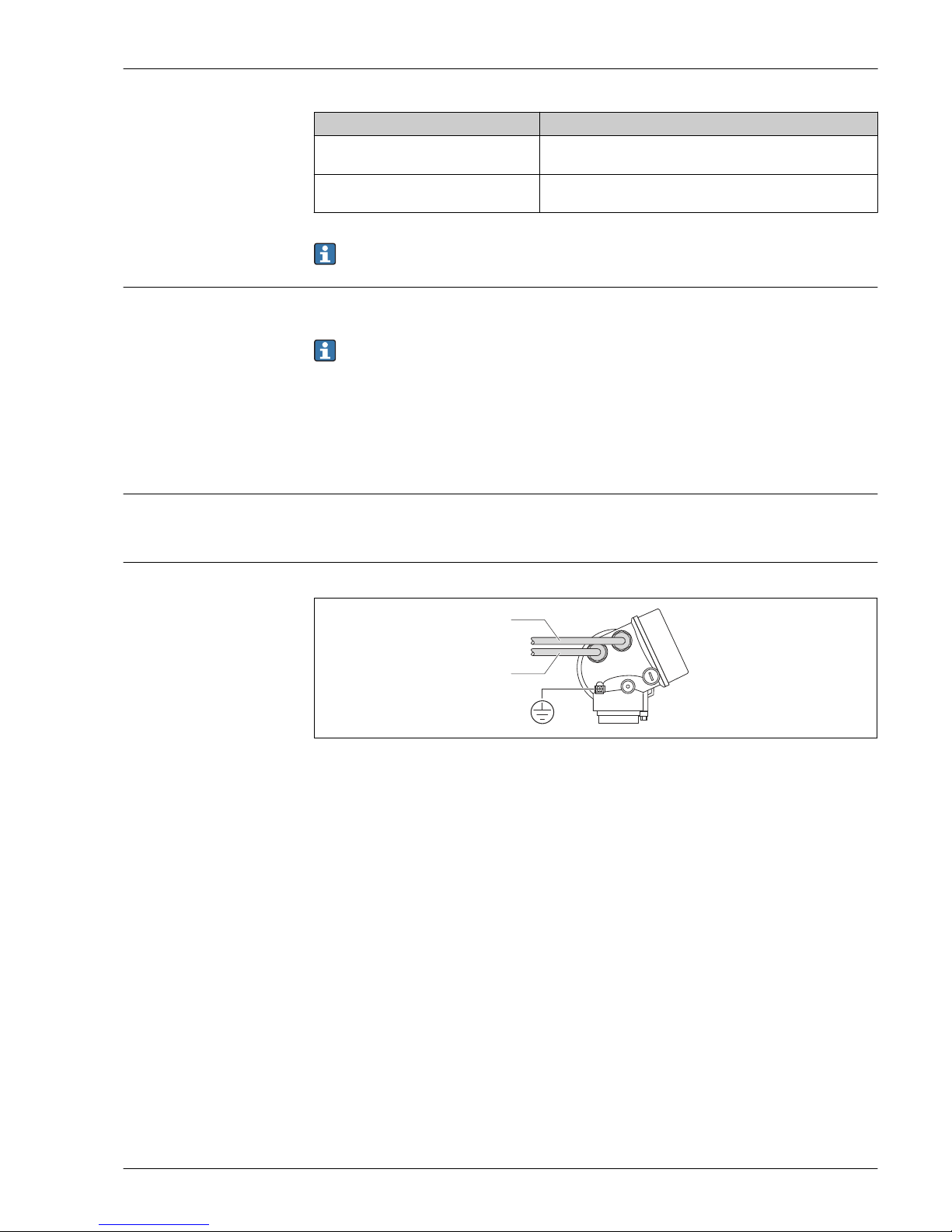
Electrical connection Connecting the transmitter
1
2
A0015510
1 Cable entry for output 1
2 Cable entry for output 2
Page 20
Proline Promag H 200
20 Endress+Hauser
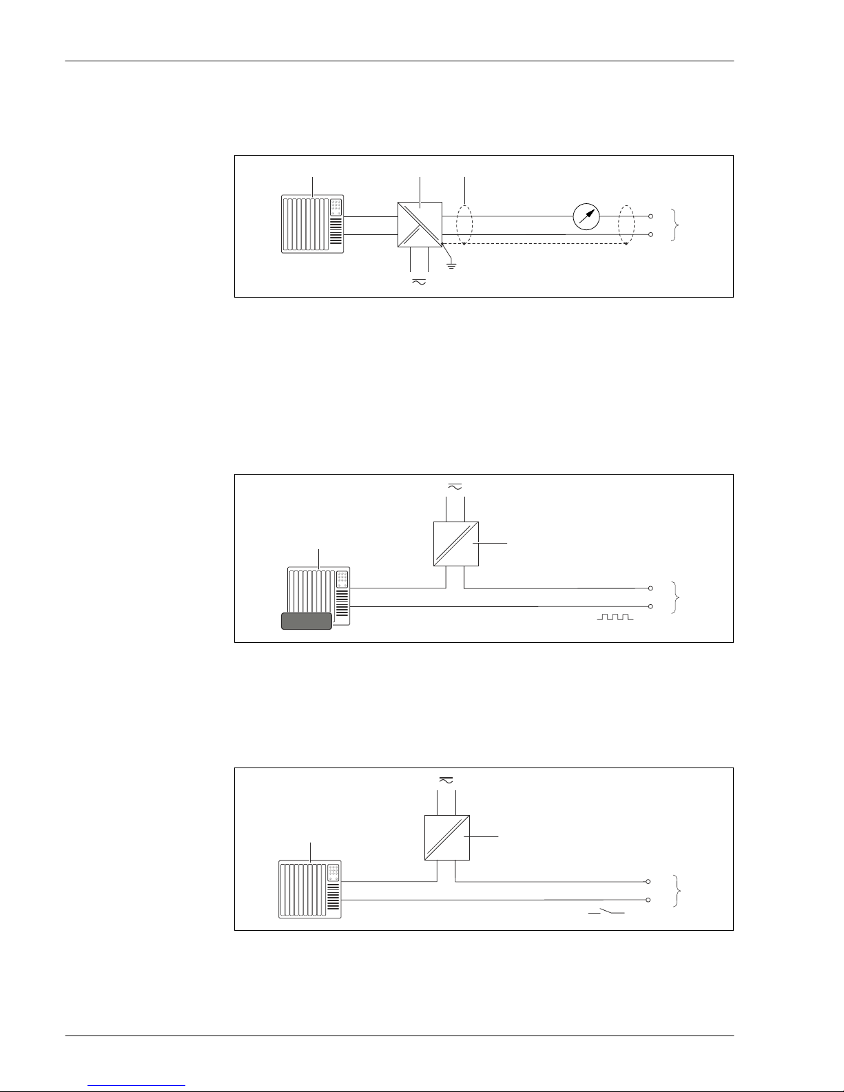
Connection examples
Current output 4-20 mA HART
2
3
4...20 mA
41
+
-
5
+
-
A0015511
1 Connection example for 4-20 mA HART current output (passive)
1 Automation system with current input (e.g. PLC)
2 Active barrier for power supply with integrated resistor for HART communication (≥ 250 Ω)(e.g. RN221N)
Connection for HART operating devices → 61
Observe the maximum load → 9
3 Cable shield, observe cable specifications
4 Analog display unit: observe maximum load → 9
5 Transmitter
Pulse/frequency output
1
+
_
12345
2
+
–
+
–
3
A0016801
2 Connection example for pulse/frequency output (passive)
1 Automation system with pulse/frequency input (e.g. PLC)
2 Power supply
3 Transmitter: observe input values → 6
Switch output
1
+
_
+
_
2
+
_
3
A0016802
3 Connection example for switch output (passive)
1 Automation system with switch input (e.g. PLC)
2 Power supply
3 Transmitter: observe input values
Page 21
Proline Promag H 200
Endress+Hauser 21
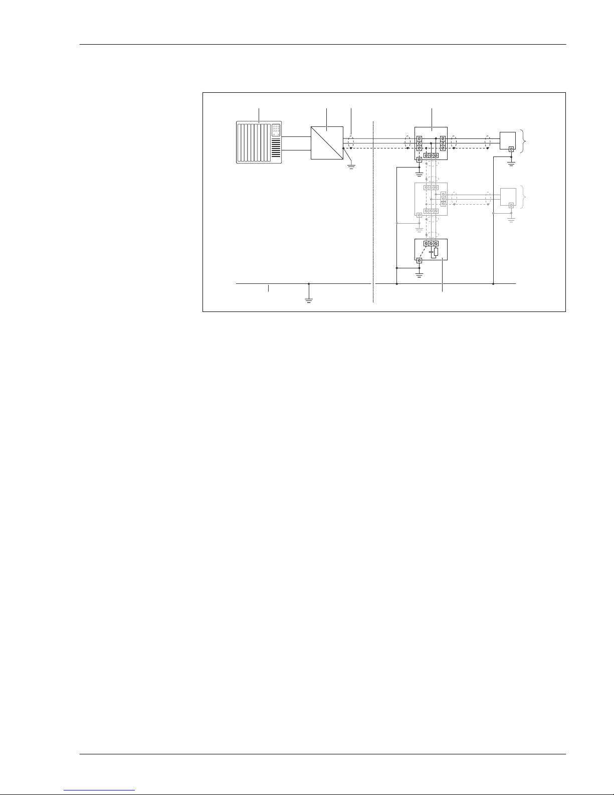
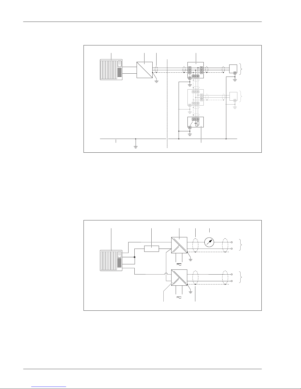
PROFIBUS-PA
21 3
+
-
+
-
+
-
4
5
5
78
6
6
6
6
6
6
.
-
A0019004
4 Connection example for PROFIBUS-PA
1 Control system (e.g. PLC)
2 Segment coupler PROFIBUS DP/PA
3 Cable shield
4 T-box
5 Measuring device
6 Local grounding
7 Bus terminator
8 Potential matching line
Page 22
Proline Promag H 200
22 Endress+Hauser
FOUNDATION Fieldbus
21 3
+
-
+
-
+
-
4
5
5
78
6
6
6
6
6
6
.
-
A0019004
5 Connection example for FOUNDATION Fieldbus
1 Control system (e.g. PLC)
2 Power Conditioner (FOUNDATION Fieldbus)
3 Cable shield
4 T-box
5 Measuring device
6 Local grounding
7 Bus terminator
8 Potential matching line
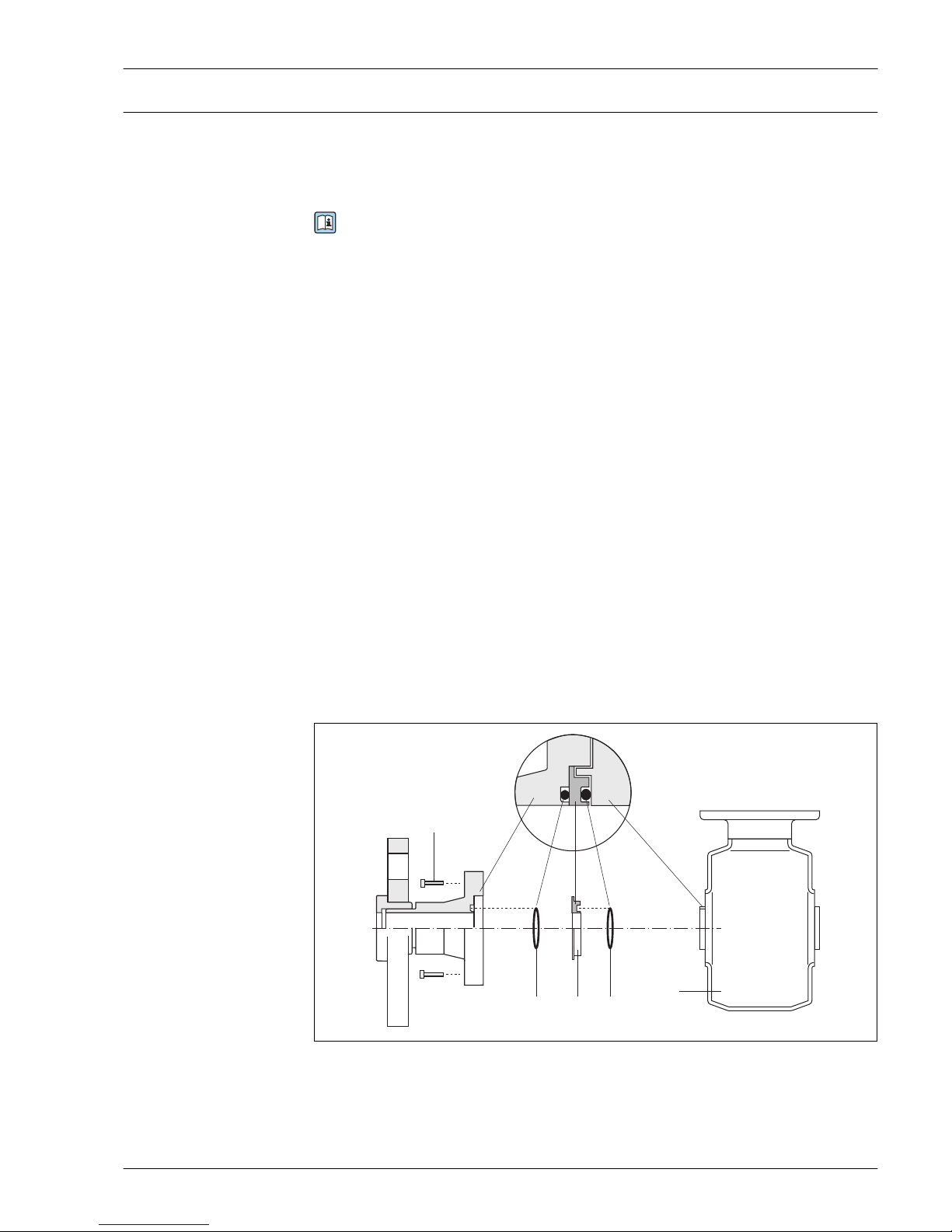
HART input
3
4...20 mA
5
1
+
-
3
6
+
–
+
+
–
+
–
+
–
+
–
–
2
4
4
7
+
-
A0016029
6 Connection example for HART input with a common negative
1 Automation system with HART output (e.g. PLC)
2 Resistor for HART communication (≥ 250 Ω): observe maximum load → 9
3 Active barrier for power supply (e.g. RN221N)
4 Cable shield, observe cable specifications
5 Analog display unit: observe maximum load → 9
6 Pressure transmitter (e.g. Cerabar M, Cerabar S): see requirements
7 Transmitter
Page 23
Proline Promag H 200
Endress+Hauser 23
Potential equalization Requirements
Please consider the following to ensure correct measurement:
• Same electrical potential for the fluid and sensor
• Company-internal grounding concepts
• Pipe material and grounding
For devices intended for use in hazardous locations, please observe the guidelines in the Ex
documentation (XA).
Connection example, standard scenario
Metal process connections
Potential equalization is generally via the metal process connections that are in contact with the
medium and mounted directly on the sensor. Therefore there is generally no need for additional
potential equalization measures.
Connection example in special situations
Plastic process connections
In the case of plastic process connections, additional grounding rings or process connections with an
integrated grounding electrode must be used to ensure potential matching between the sensor and
the fluid. If there is no potential matching, this can affect the measuring accuracy or cause the
destruction of the sensor as a result of the electrochemical decomposition of the electrodes.
Note the following when using grounding rings:
• Depending on the option ordered, plastic disks are used instead of grounding rings on some
process connections. These plastic disks only act as "spacers" and do not have any potential
matching function. Furthermore, they also perform a significant sealing function at the sensor/
connection interface. Therefore, in the case of process connections without metal grounding rings,
these plastic disks/seals should never be removed and should always be installed!
• Grounding rings can be ordered separately as an accessory from Endress+Hauser . When ordering
make sure that the grounding rings are compatible with the material used for the electrodes, as
otherwise there is the danger that the electrodes could be destroyed by electrochemical corrosion!
• Grounding rings, including seals, are mounted inside the process connections. Therefore the
installation length is not affected.
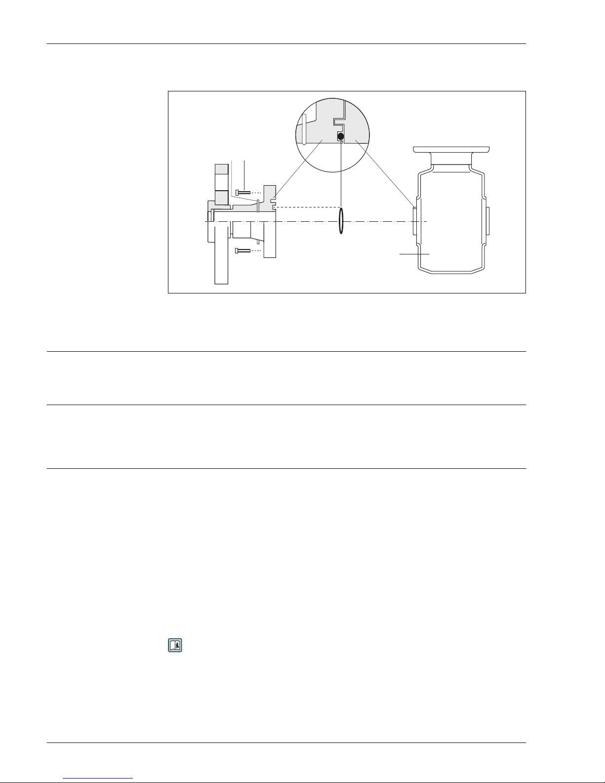
Potential equalization via additional grounding ring
1
3
2
4
2
A0002651
1 Hexagonal-headed bolts of process connection
2 O-ring seals
3 Plastic disk (spacer) or grounding ring
4 Sensor
Page 24
Proline Promag H 200
24 Endress+Hauser
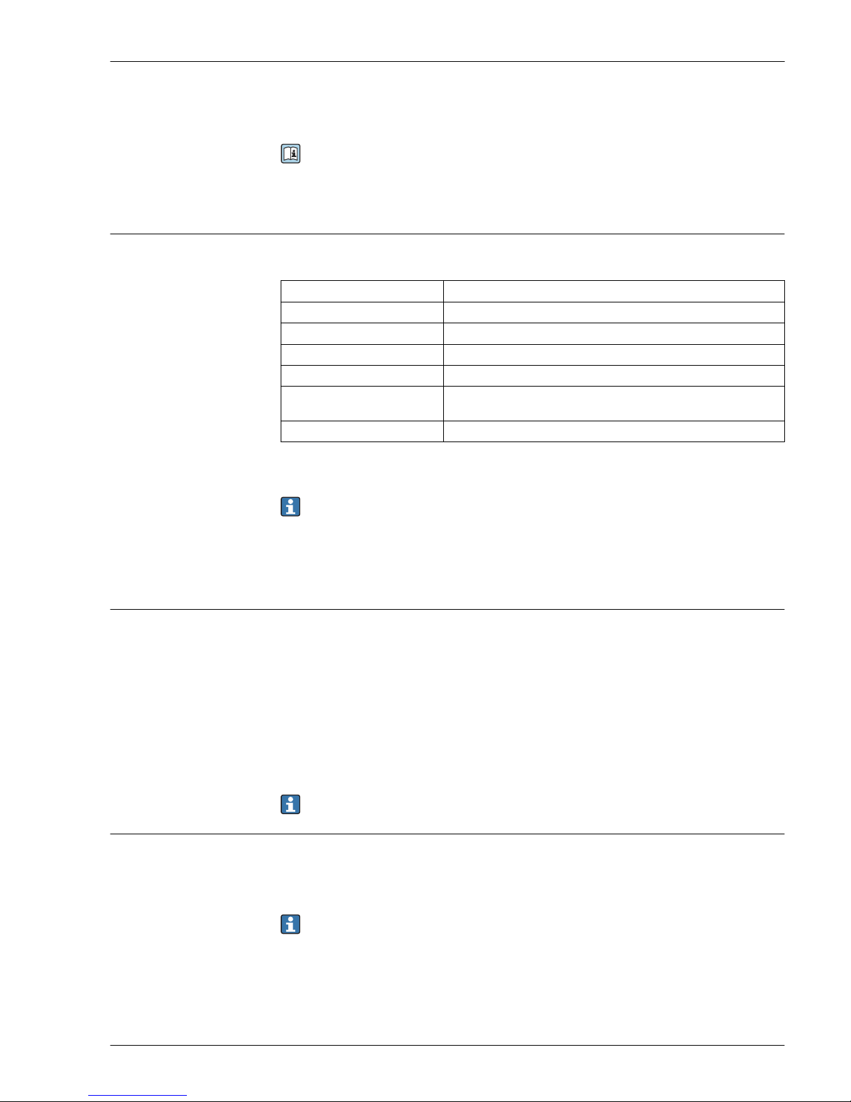
Potential equalization via grounding electrodes on process connection
2
1
3
4
A0017293
1 Hexagonal-headed bolts of process connection
2 Integrated grounding electrodes
3 O-ring seal
4 Sensor
Terminals
• For device version without integrated overvoltage protection: plug-in spring terminals for wire
cross-sections 0.5 to 2.5 mm2 (20 to 14 AWG)
• For device version with integrated overvoltage protection: screw terminals for wire cross-sections
0.2 to 2.5 mm2 (24 to 14 AWG)
Cable entries
• Cable gland (not for Ex d): M20 × 1.5 with cable 6 to 12 mm (0.24 to 0.47 in)
• Thread for cable entry:
– For non-Ex and Ex: NPT ½"
– For non-Ex and Ex (not for CSA Ex d/XP): G ½"
– For Ex d: M20 × 1.5
Cable specification Permitted temperature range
• –40 °C (–40 °F) to +80 °C (+176 °F)
• Minimum requirement: cable temperature range ≥ ambient temperature +20 K
Signal cable
Current output
For 4-20 mA HART: Shielded cable recommended. Observe grounding concept of the plant.
Pulse/frequency/switch output
Standard installation cable is sufficient.
FOUNDATION Fieldbus
Twisted, shielded two-wire cable.
For further information on planning and installing FOUNDATION Fieldbus networks see:
• Operating Instructions for "FOUNDATION Fieldbus Overview" (BA00013S)
• FOUNDATION Fieldbus Guideline
• IEC 61158-2 (MBP)
Page 25
Proline Promag H 200
Endress+Hauser 25
PROFIBUS PA
Twisted, shielded two-wire cable. Cable type A is recommended.
For further information on planning and installing PROFIBUS PA networks see:
• Operating Instructions "PROFIBUS DP/PA: Guidelines for planning and commissioning"
(BA00034S)
• PNO Directive 2.092 "PROFIBUS PA User and Installation Guideline"
• IEC 61158-2 (MBP)
Overvoltage protection
The device can be ordered with integrated overvoltage protection for diverse approvals:
Order code for "Accessory mounted", option NA "Overvoltage protection"
Input voltage range Values correspond to supply voltage specifications
1)
Resistance per channel 2 ⋅ 0.5 Ω max
DC sparkover voltage 400 to 700 V
Trip surge voltage < 800 V
Capacitance at 1 MHz < 1.5 pF
Nominal discharge current
(8/20 μs)
10 kA
Temperature range –40 to +85 °C (–40 to +185 °F)
1) The voltage is reduced by the amount of the internal resistance I
min
⋅ R
i
Depending on the temperature class, restrictions apply to the ambient temperature for device
versions with overvoltage protection
Performance characteristics
Reference operating
conditions
In accordance with DIN EN 29104
• Water, typically 15 to 45 °C (59 to 113 °F); 2 to 6 bar (29 to 87 psi)
• Data as indicated in the calibration protocol ±5 °C (±41 °F) and ±2 bar (±29 psi)
• Accuracy based on accredited calibration rigs traced to ISO 17025
• Medium temperature: +28 ± 2 °C (+82 ± 4 °F)
• Ambient temperature: +22 ± 2 °C (+72 ± 4 °F)
• Warm-up period: 30 min
Installation
• Inlet run > 10 × DN
• Outlet run > 5 × DN
• Sensor and transmitter grounded.
• The sensor is centered in the pipe.
To calculate the measuring range, use the Applicator sizing tool → 68
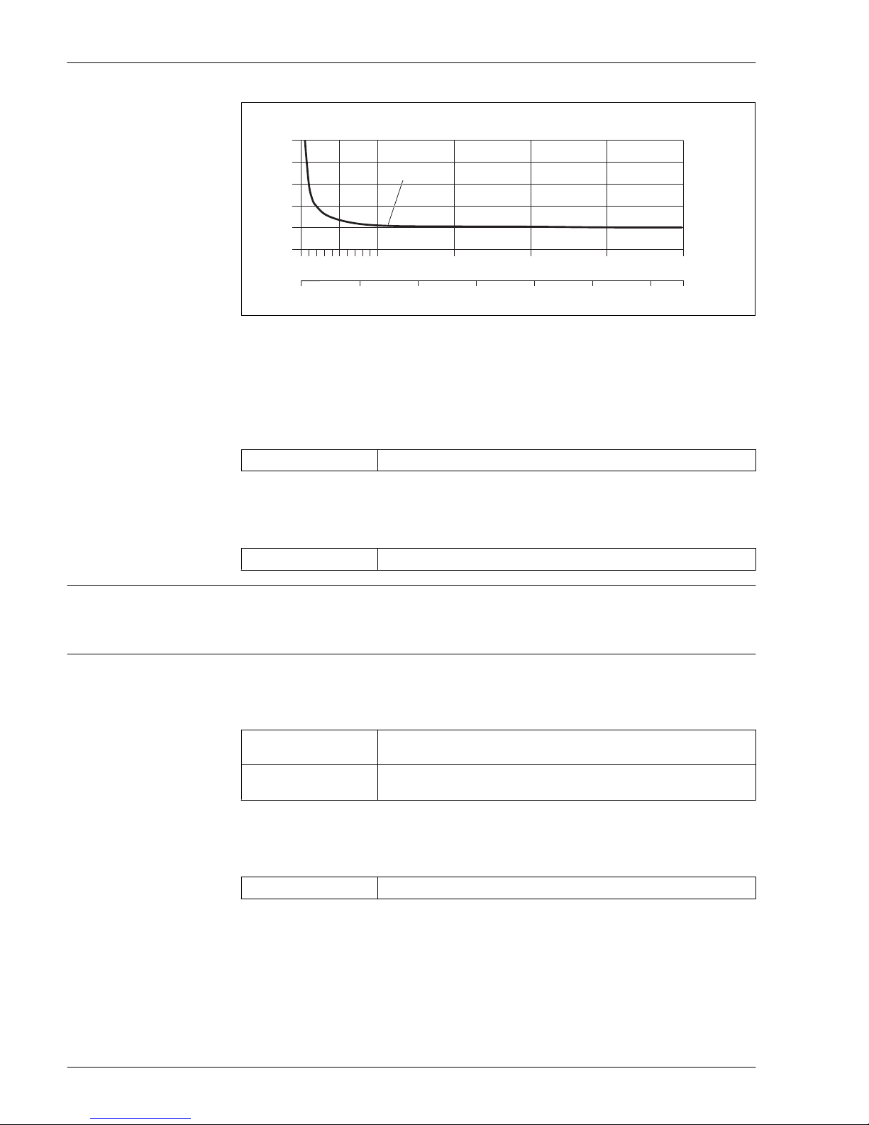
Maximum measured error Error limits under reference operating conditions
o.r. = of reading
Volume flow
±0.5 % o.r. ± 2 mm/s (0.08 in/s)
Fluctuations in the supply voltage do not have any effect within the specified range.
Page 26
Proline Promag H 200
26 Endress+Hauser
2.5
[%]
2.0
1.5
1.0
0.5
0
0.5 %
0
1
2 4 6 8 10 [m/s]
v
5 10 15 20 25 30 32 [ft/s]0
A0003200
7 Maximum measured error in % o.r.
Accuracy of outputs
The outputs have the following base accuracy specifications.
Current output
Accuracy ±10 µA
Pulse/frequency output
o.r. = of reading
Accuracy Max. ±100 ppm o.r.
Repeatability
o.r. = of reading
Volume flow
Max. ±0.2 % o.r. ± 2 mm/s (0.08 in/s)
Influence of ambient
temperature
Current output
o.r. = of reading
Additional error, in relation to the span of 16 mA:
Temperature coefficient at
zero point (4 mA)
0.02 %/10 K
Temperature coefficient
with span (20 mA)
0.05 %/10 K
Pulse/frequency output
o.r. = of reading
Temperature coefficient Max. ±100 ppm o.r.
Installation
No special measures such as supports are necessary. External forces are absorbed by the construction
of the device.
Page 27
Proline Promag H 200
Endress+Hauser 27
Mounting location
h
A0023343
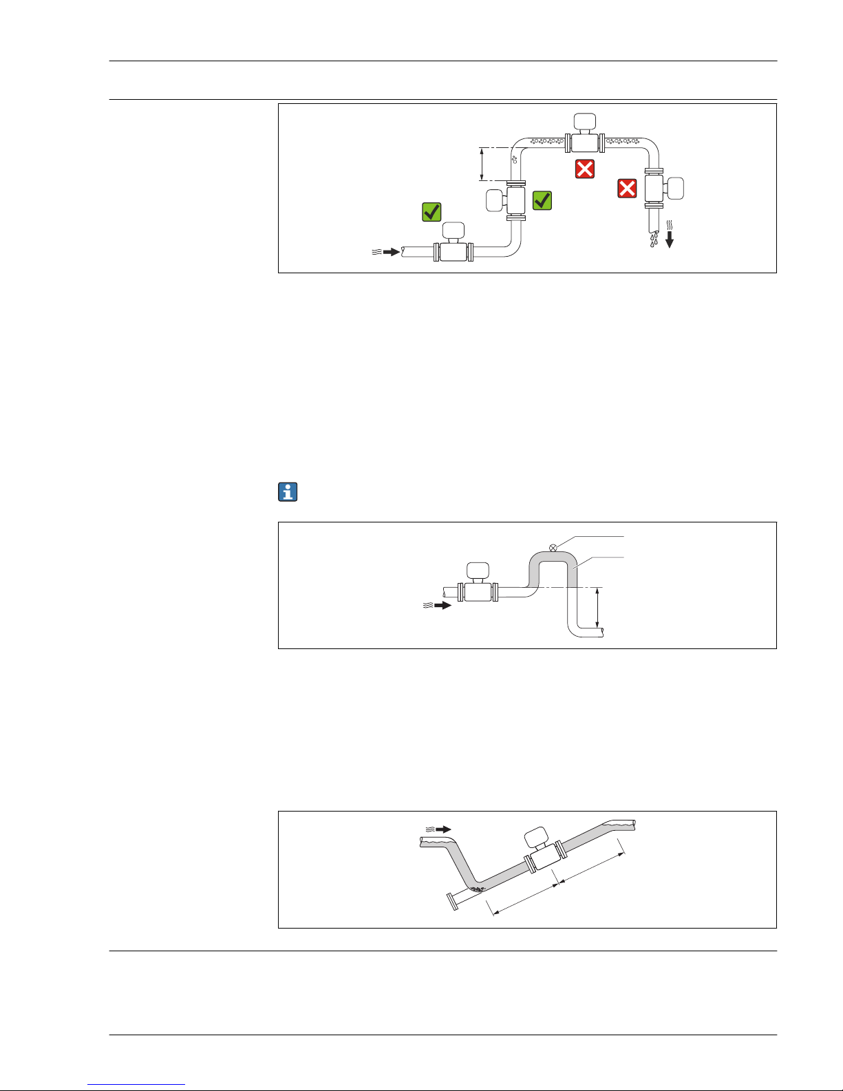
Preferably install the sensor in an ascending pipe, and ensure a sufficient distance to the next pipe
elbow: h ≥ 2 × DN
To prevent measuring errors arising from accumulation of gas bubbles in the measuring tube, avoid
the following mounting locations in the pipe:
• Highest point of a pipeline.
• Directly upstream of a free pipe outlet in a down pipe.
Installation in down pipes
Install a siphon with a vent valve downstream of the sensor in down pipes whose length h ≥ 5 m
(16.4 ft). This precaution is to avoid low pressure and the consequent risk of damage to the
measuring tube. This measure also prevents the system losing prime.
For information on the liner's resistance to partial vacuum
h
2
1
A0017064
8 Installation in a down pipe
1 Vent valve
2 Pipe siphon
h Length of down pipe
Installation in partially filled pipes
A partially filled pipe with a gradient necessitates a drain-type configuration. The empty pipe
detection (EPD) function offers additional protection by detecting empty or partially filled pipes.
³ 5 × DN
³ 2 × DN
A0017063
Orientation
The direction of the arrow on the sensor nameplate helps you to install the sensor according to the
flow direction (direction of medium flow through the piping).
An optimum orientation position helps avoid gas and air accumulations and deposits in the
measuring tube.
Page 28
Proline Promag H 200
28 Endress+Hauser
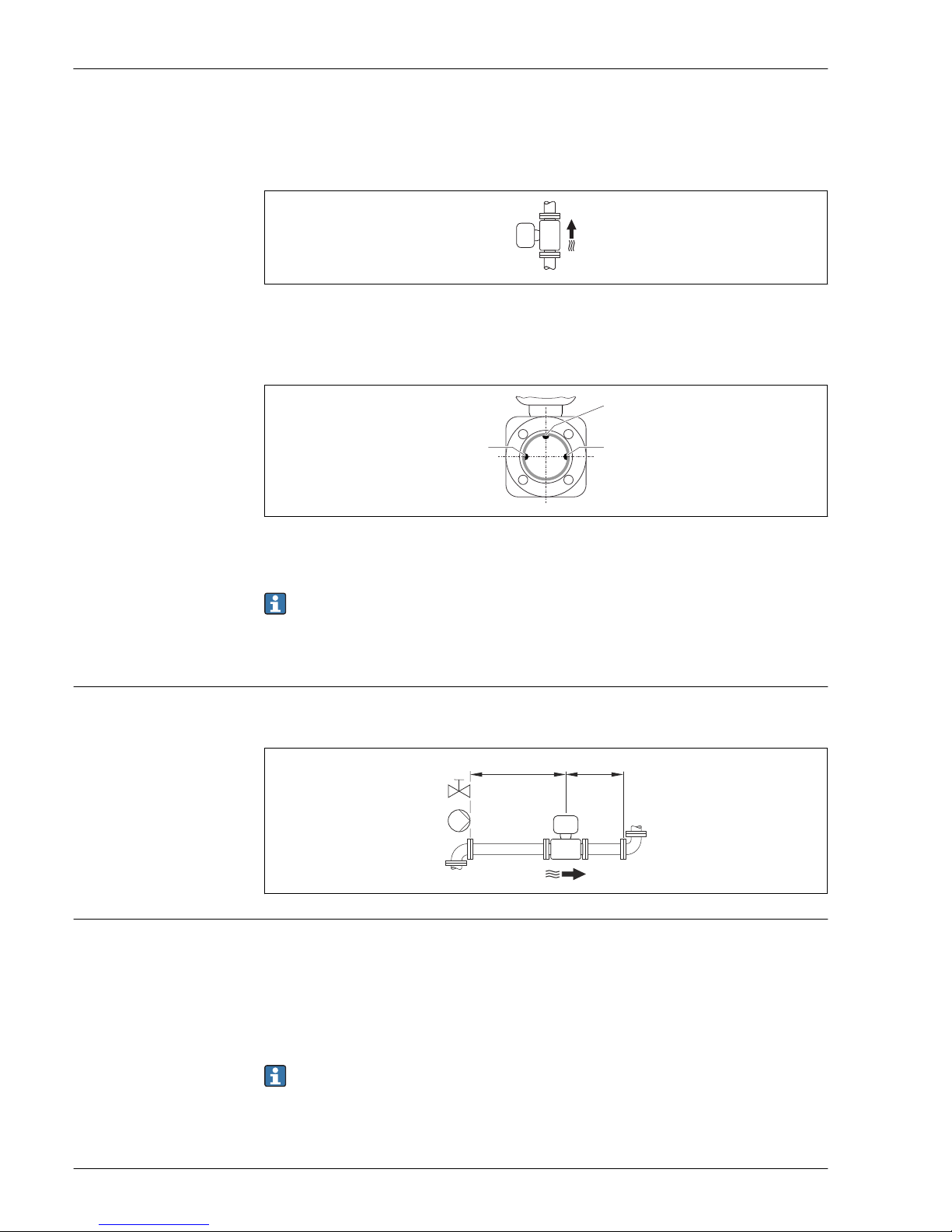
The measuring device also offers the empty pipe detection function to detect partially filled
measuring pipes in the event of outgassing fluids or variable process pressures.
Vertical
A0015591
Optimum for self-emptying pipe systems and for use in conjunction with empty pipe detection.
Horizontal
1
22
A0019602
1 EPD electrode for empty pipe detection
2 Measuring electrodes for signal detection
• The measuring electrode plane must be horizontal. This prevents brief insulation of the two
measuring electrodes by entrained air bubbles.
• Empty pipe detection only works if the transmitter housing is pointing upwards as otherwise
there is no guarantee that the empty pipe detection function will actually respond to a
partially filled or empty measuring tube.
Inlet and outlet runs
If possible, install the sensor upstream from fittings such as valves, T-pieces or elbows.
Observe the following inlet and outlet runs to comply with accuracy specifications:
5 × DN≥
2 × DN≥
A0016275
Adapters
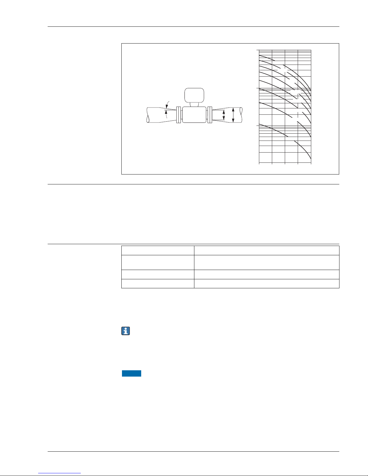
Suitable adapters to DIN EN 545 (double-flange reducers) can be used to install the sensor in largerdiameter pipes. The resultant increase in the rate of flow improves measuring accuracy with very
slow-moving fluids.
The nomogram shown here can be used to calculate the pressure loss caused by reducers and
expanders:
• Calculate the ratio of the diameters d/D.
• From the nomogram read off the pressure loss as a function of flow velocity (downstream from
the reduction) and the d/D ratio.
The nomogram only applies to liquids with a viscosity similar to that of water.
Page 29
Proline Promag H 200
Endress+Hauser 29
100
10
0.5
d / D
[mbar]
0.6 0.7 0.8 0.9
1 m/s
2 m/s
3 m/s
4 m/s
5 m/s
6 m/s
7 m/s
8 m/s
1
D
d
max. 8°
A0016359
Special mounting
instructions
Display protection
To ensure that the optional display protection can be easily opened, maintain the following
minimum head clearance: 350 mm (13.8 in)
Environment
Ambient temperature range
Transmitter –40 to +60 °C (–40 to +140 °F)
Local display –20 to +60 °C (–4 to +140 °F), the readability of the display may be
impaired at temperatures outside the temperature range.
Sensor –20 to +60 °C (–4 to +140 °F)
Liner Do not exceed or fall below the permitted temperature range of the liner .
If operating outdoors:
• Install the measuring device in a shady location.
• Avoid direct sunlight, particularly in warm climatic regions.
• Avoid direct exposure to weather conditions.
Weather protection covers can be ordered from Endress+Hauser: see "Accessories" section
→ 67
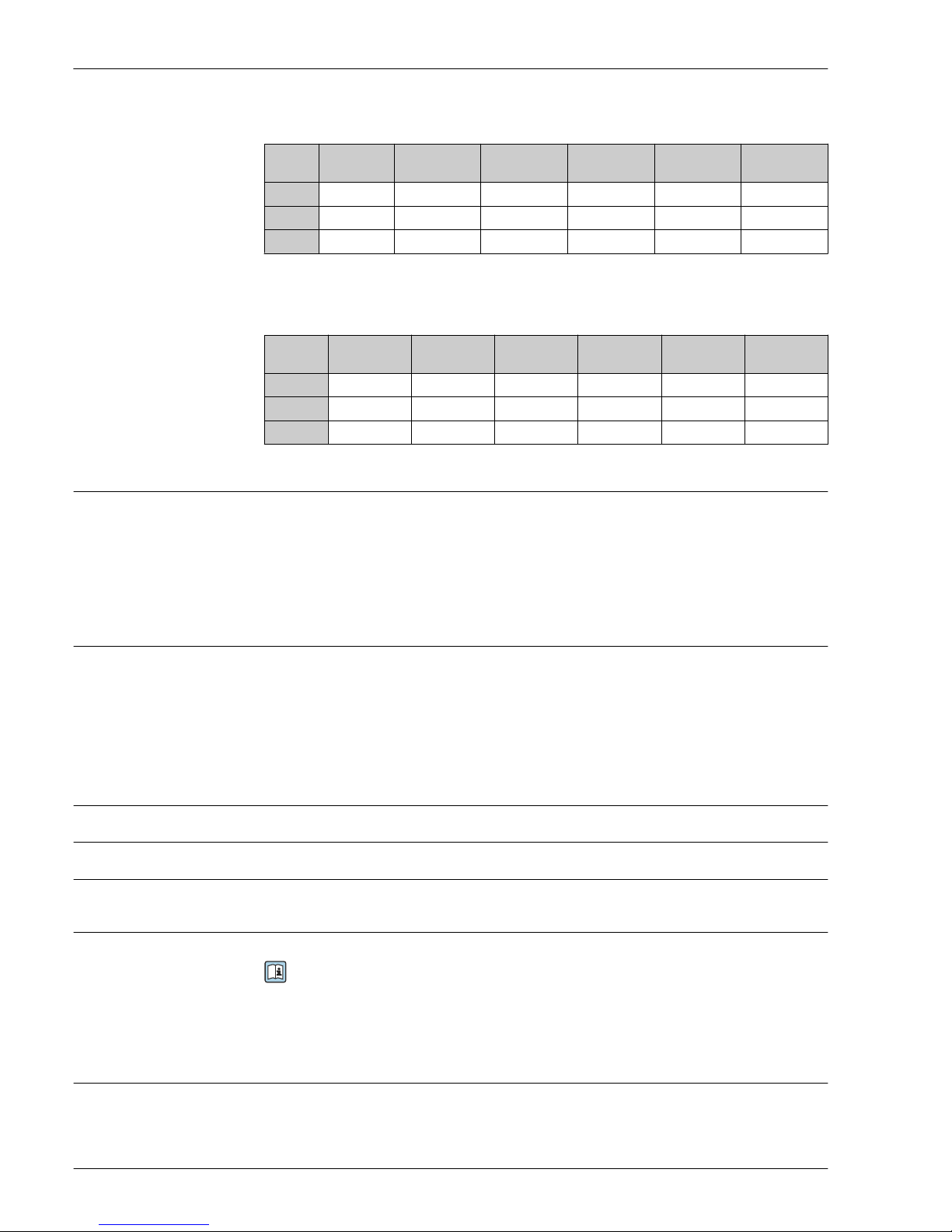
Temperature tables
The following interdependencies between the permitted ambient and fluid temperatures apply when
operating the device in hazardous areas:
NOTICE
The ambient temperature changes for installations with overvoltage protection in conjunction
with temperature classes T5 and T6.
The following applies for basic specification, position 1, 2 (approval) = BJ, B5, BH, IJ, I6, IH, C2, NF,
N6, NH, NK, MJ:
‣
Ta = Ta - 2 K
Page 30
Proline Promag H 200
30 Endress+Hauser
SI units
T
a
[°C]
T6
[85 °C]
T5
[100 °C]
T4
[135 °C]
T3
[200 °C]
T2
[300 °C]
T1
[450 °C]
40 80 95 130 150 150 150
55 – 95 130 150 150 150
60
1)
– 95 130 150 150 150
1) The following applies for Basic specification, Position 3 (Output) = A, B, E, G: Pi = 0.85 W
US units
T
a
[°F]
T6
[185 °F]
T5
[212 °F]
T4
[275 °F]
T3
[392 °F]
T2
[572 °F]
T1
[842 °F]
104 176 203 266 302 302 302
131 – 203 266 302 302 302
140
1)
– 203 266 302 302 302
1) The following applies for basic specification, position 3 (output) = A, B, E, G: Pi = 0.85 W
Storage temperature
The storage temperature corresponds to the operating temperature range of the measuring
transmitter and the appropriate measuring sensors.
• Protect the measuring device against direct sunlight during storage in order to avoid unacceptably
high surface temperatures.
• Select a storage location where moisture cannot collect in the measuring device as fungus or
bacteria infestation can damage the liner.
• If protection caps or protective covers are mounted these should never be removed before
installing the measuring device.
Degree of protection
Transmitter
• As standard: IP66/67, type 4X enclosure
• When housing is open: IP20, type 1 enclosure
• Display module: IP20, type 1 enclosure
Sensor
IP66/67, type 4X enclosure
Connector
IP67, only in screwed situation
Shock resistance
As per IEC/EN 60068-2-31
Vibration resistance
Acceleration up to 2 g, according to IEC 60068-2-6
Mechanical load
• Protect the transmitter housing against mechanical effects, such as shock or impact.
• Never use the transmitter housing as a ladder or climbing aid.
Electromagnetic
compatibility (EMC)
As per IEC/EN 61326 and NAMUR Recommendation 21 (NE 21)
For details, refer to the Declaration of Conformity.
Process
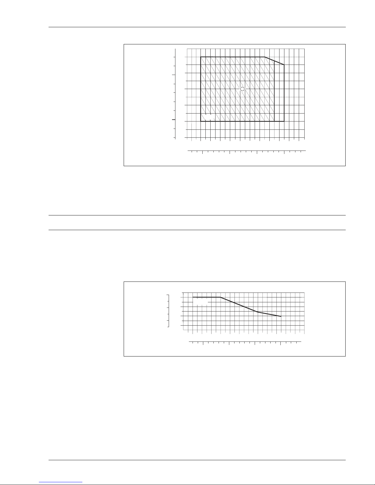
Medium temperature range
–20 to +150 °C (–4 to +302 °F) for PFA
Page 31
Proline Promag H 200
Endress+Hauser 31
PFA
0
0
0
0
-20-40
-40
20
20
40
100
60
140
[°F] [°C]
40 60 80 100
100
120 140 160
200 300
180
360
-20
-40
-40
T
A
T
F
[°F]
[°C]
1
A0019805
TAAmbient temperature
TFMedium temperature
1 Hatched area: harsh environment only up to +130 °C (+266 °F)
Conductivity
≥ 20 μS/cm for liquids in general
Pressure-temperature
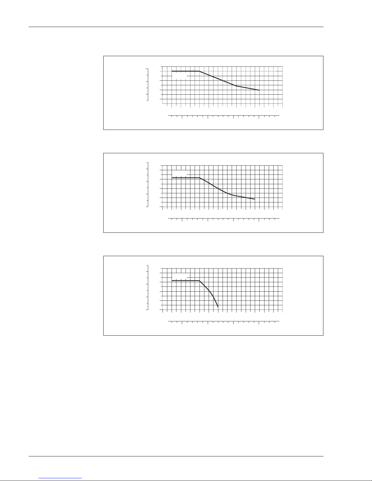
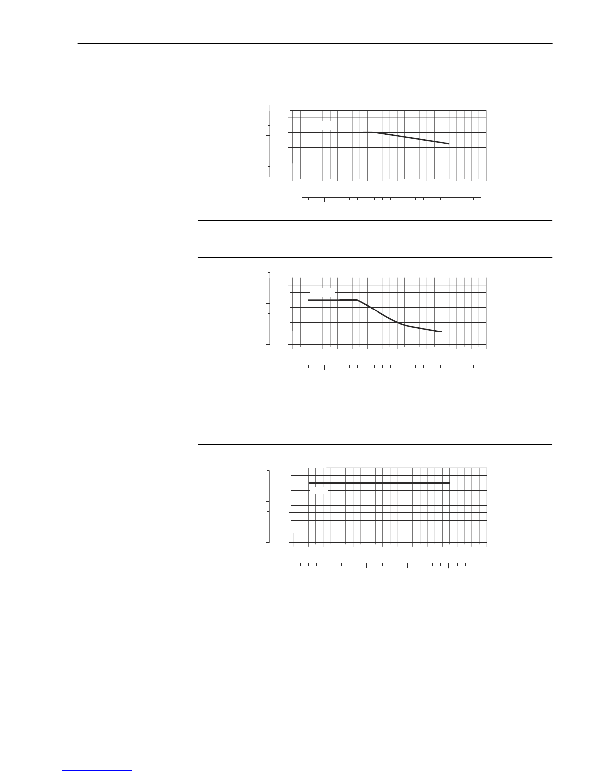
ratings
The following pressure-temperature ratings refer to the entire device and not just the process
connection.
Process connections with O-ring seal, DN 2 to 25 (1/12 to 1")
Process connection: weld-in nipple according to DIN EN ISO 1127, ODT/SMS, ISO 2037; coupling
according to ISO 228 / DIN 2999, NPT
25
35
30
40
[bar][psi]
-40
-20
0 20
40 60 80 100 120140 160180 [°C]
360 [°F]
0-40 100 200 300
400
500
600
PN40
A0021191-EN
9 Process connection material: stainless steel, 1.4404 (F316L)
Page 32
Proline Promag H 200
32 Endress+Hauser
Process connection: flange according to EN 1092-1 (DIN 2501), adhesive sleeve
25
35
30
40
[bar][psi]
-40
-20
0 20
40 60 80 100 120140 160180 [°C]
360 [°F]
0-40 100 200 300
400
500
600
PN40
A0021191-EN
10 Process connection material: stainless steel, 1.4404 (F316L)
0
5
10
15
20
[bar][psi]
-60
-40
-20
0 20
40 60 80 100 120140 160180 [°C]
360 [°F]
0-40 100 200 300
200
100
300
0
PN16
A0021230-EN
11 Process connection material: PVDF
0
5
10
15
20
[bar][psi]
-60
-40
-20
0 20
40 60 80 100 120140 160180 [°C]
360 [°F]
0-40 100 200 300
200
100
300
0
PN16
A0021231-EN
12 Process connection material: PVC-U
Page 33
Proline Promag H 200
Endress+Hauser 33
Process connection: flange according to ASME B16.5
0
5
15
10
20
[bar][psi]
-40
-20
0 20
40 60 80 100 120140 160180 [°C]
360 [°F]
0-40 100 200 300
100
200
300
0
Cl150
A0021192-EN
13 Process connection material: stainless steel, 1.4404 (F316L)
0
5
15
10
20
[bar][psi]
-40
-20
0 20
40 60 80 100 120140 160180 [°C]
360 [°F]
0-40 100 200 300
100
200
300
0
Cl150
A0021232-EN
14 Process connection material: PVDF
Process connection: flange according to JIS B2220
0
5
15
10
20
[bar][psi]
-40
-20
0 20
40 60 80 100 120140 160180 [°C]
360 [°F]
0-40 100 200 300
100
200
300
25
0
20K
A0021193-EN
15 Process connection material: stainless steel, 1.4404 (F316L)
Page 34
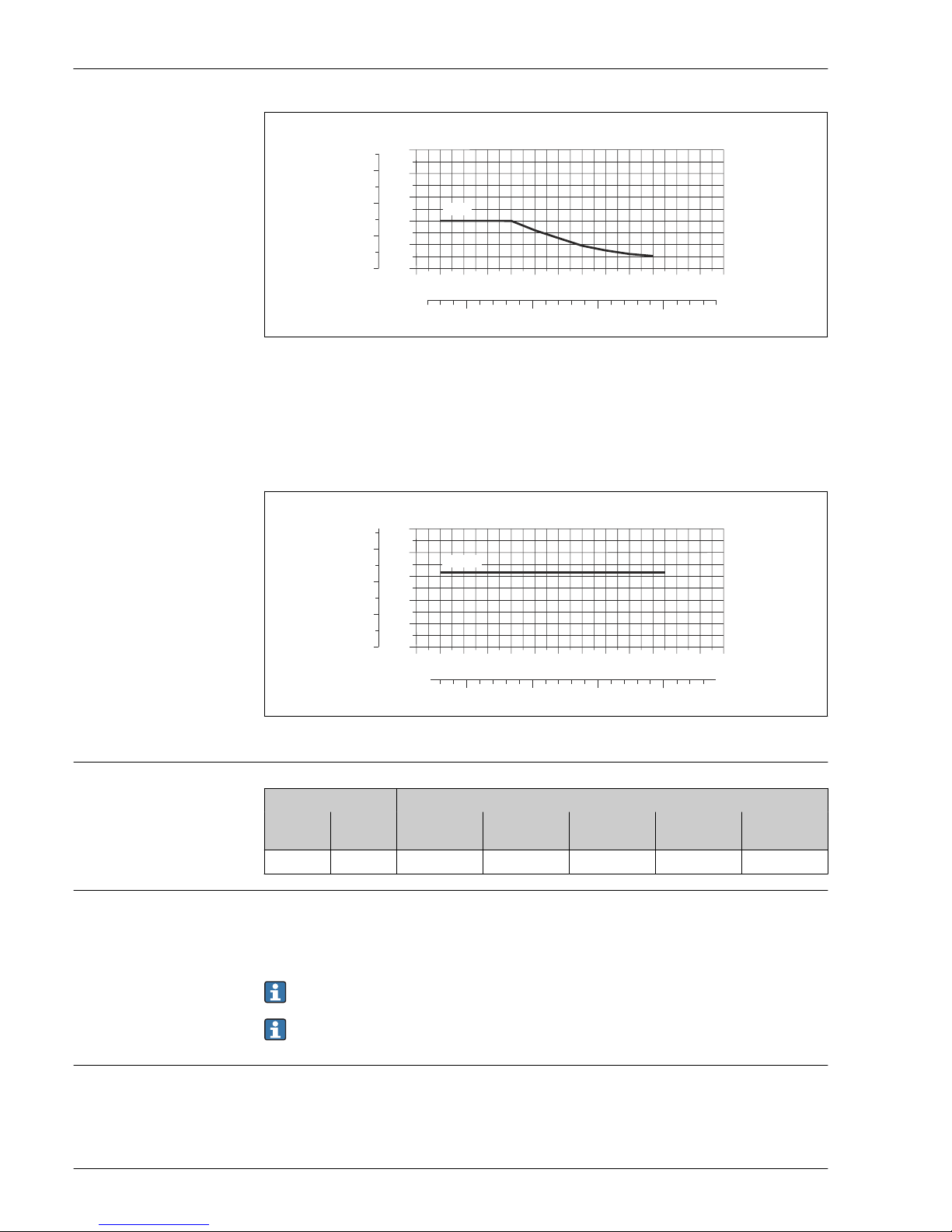
Proline Promag H 200
34 Endress+Hauser
0
5
15
10
20
[bar][psi]
-40
-20
0 20
40 60 80 100 120140 160180 [°C]
360 [°F]
0-40 100 200 300
100
200
300
25
0
10K
A0021233-EN
16 Process connection material: PVDF
Process connections with aseptic molded seal, DN 2 to 25 (1/12 to 1")
Process connection: weld-in nipple according to EN 10357 (DIN 11850), ASME BPE, ISO 2037; Clamp
according to ISO 2852, DIN 32676, L14 AM7; coupling according to SC DIN 11851, DIN 11864-1,
SMS 1145; flange according to DIN 11864-2
PN16
[bar]
-60
-40
-20
0 20
40 60 80 100 120140 160180 [°C]
0
5
15
10
20
25
[psi]
360 [°F]
0-40 100 200 300
100
200
300
0
A0021190-EN
17 Process connection material: stainless steel, 1.4404 (F316L)
Pressure tightness
Liner: PFA
Nominal diameter Limit values for absolute pressure in [mbar] ([psi]) for fluid temperatures:
[mm] [in] +25 °C
(+77 °F)
+80 °C
(+176 °F)
+100 °C
(+212 °F)
+130 °C
(+266 °F)
+150 °C
(+302 °F)
2 to 25 ¹⁄₁₂ to 1 0 (0) 0 (0) 0 (0) 0 (0) 0 (0)
Flow limit
The diameter of the pipe and the flow rate determine the nominal diameter of the sensor. The
optimum velocity of flow is between 2 to 3 m/s (6.56 to 9.84 ft/s). Also match the velocity of flow
(v) to the physical properties of the fluid:
• v < 2 m/s (6.56 ft/s): for abrasive fluids
• v > 2 m/s (6.56 ft/s): for fluids producing buildup
A necessary increase in the flow velocity can be achieved by reducing the sensor nominal
diameter.
For an overview of the measuring range full scale values, see the "Measuring range" section
→ 5
Pressure loss
• No pressure loss occurs as of nominal diameter DN 8 (3/8") if the sensor is installed in a pipe with
the same nominal diameter.
• Pressure losses for configurations incorporating adapters according to DIN EN 545 → 28
Page 35
Proline Promag H 200
Endress+Hauser 35
System pressure
A0015594
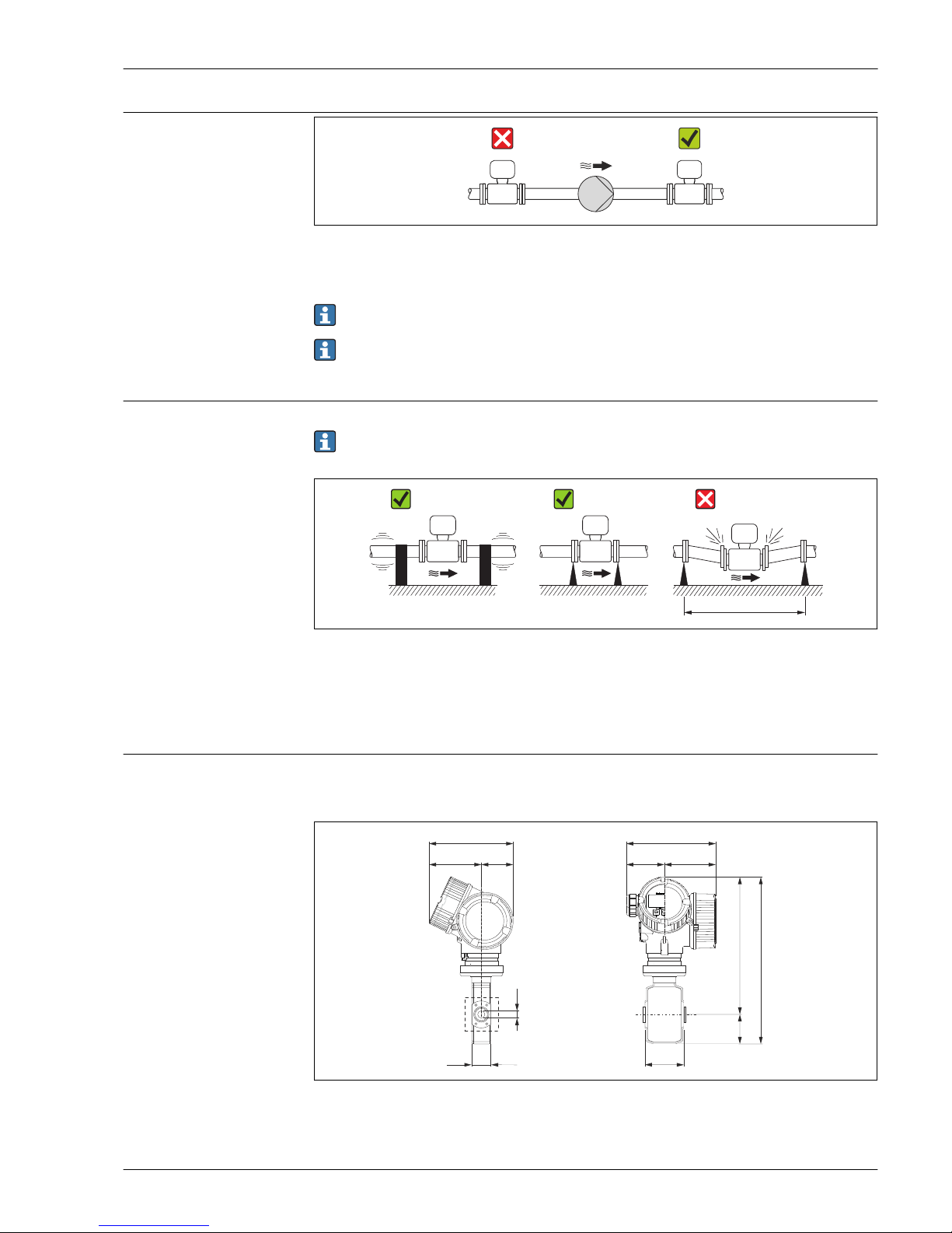
Never install the sensor on the pump suction side in order to avoid the risk of low pressure, and thus
damage to the liner.
Furthermore, install pulse dampers if reciprocating, diaphragm or peristaltic pumps are used.
• For information on the liner's resistance to partial vacuum → 34
• For information on the shock resistance of the measuring system → 30
• For information on the vibration resistance of the measuring system → 30
Vibrations
In the event of very strong vibrations, the pipe and sensor must be supported and fixed.
• For information on the shock resistance of the measuring system → 30
• For information on the vibration resistance of the measuring system → 30
L
A0016266
18 Measures to avoid device vibrations (L > 10 m (33 ft))
Mechanical construction
Dimensions in SI units Compact version
Order code for "Housing", option C "GT20 dual compartment, aluminum coated"
G
di
Q
C
A
B
J
H
K
FE
D
L
A0017653
Page 36
Proline Promag H 200
36 Endress+Hauser
DN A B
1)
C D
2)
E F
2)
G H
3)
J K
3)L 4)
Q di
[mm] [mm] [mm] [mm] [mm] [mm] [mm] [mm] [mm] [mm] [mm] [mm] [mm] [mm]
2 162 102 60 165 75 90 43 265 48 313 86
4 ×
M6
2.25
4 162 102 60 165 75 90 43 265 48 313 86
4 ×
M6
4.5
8 162 102 60 165 75 90 43 265 48 313 86
4 ×
M6
9
15 162 102 60 165 75 90 43 265 48 313 86
4 ×
M6
16
25 162 102 60 165 75 90 53 269 52 321 86
4 ×
M6
26
1) For version without local display: values - 7 mm
2) For version with overvoltage protection (OVP): values + 8 mm
3) For version without local display: values - 10 mm
4) Total length (L) depends on the process connections.
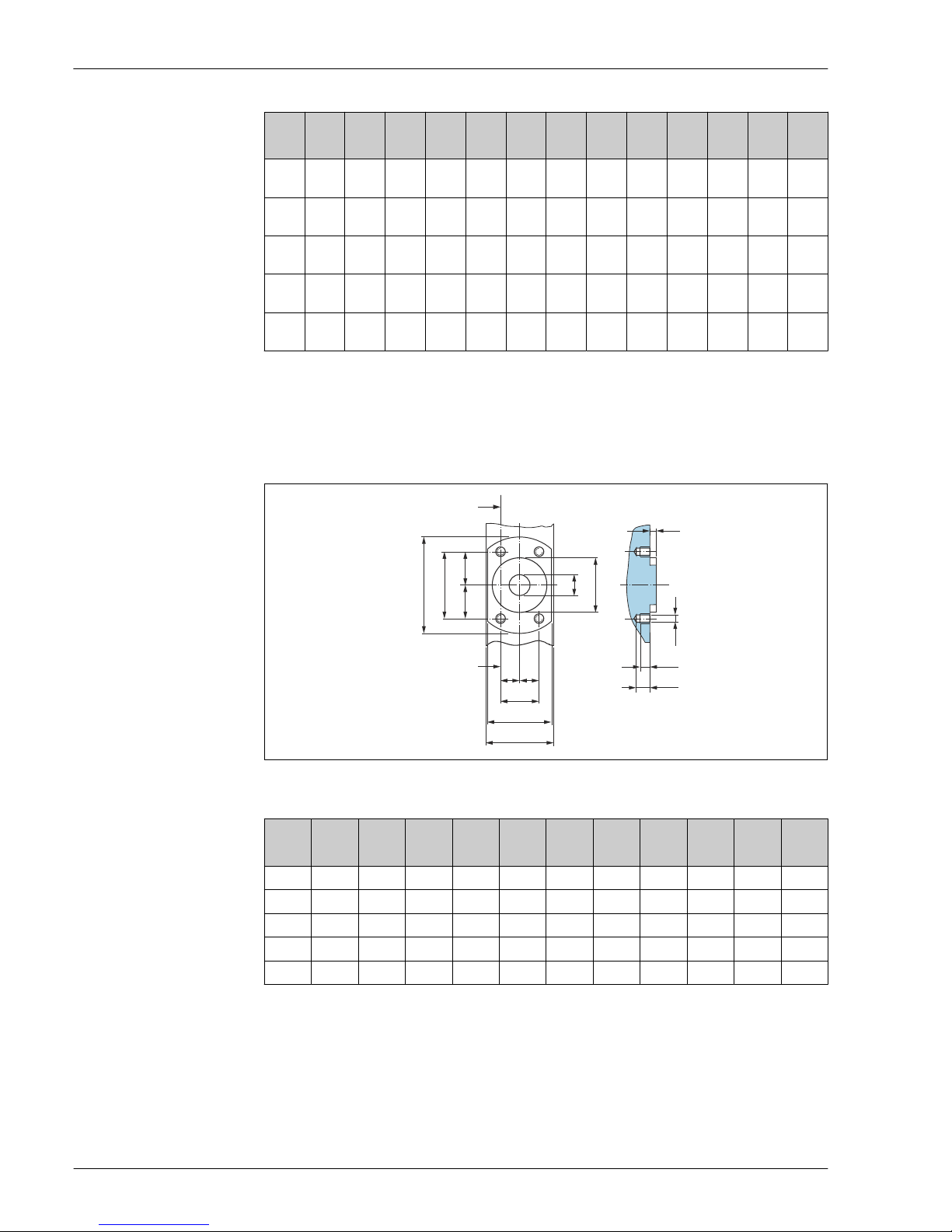
Sensor flange connection
G
F
K
H
E
Z
Z Z-Z
L
A
B
D
M
C
B/2
B/2
E
–
2
E
–
2
A0017657
19 Front view without process connections
DN A B C D E F G H K L M
[mm] [mm] [mm] [mm] [mm] [mm] [mm] [mm] [mm] [mm] [mm] [mm]
2 62 41.6 34 9 24 42 43 8.5 6 4 M6
4 62 41.6 34 9 24 42 43 8.5 6 4 M6
8 62 41.6 34 9 24 42 43 8.5 6 4 M6
15 62 41.6 34 16 24 42 43 8.5 6 4 M6
25 72 50.2 44 26 29 55 56 8.5 6 4 M6
Page 37
Proline Promag H 200
Endress+Hauser 37
Flanges
Flanges with aseptic molded seal
C
D
A
B
E
X X
L
A0015627
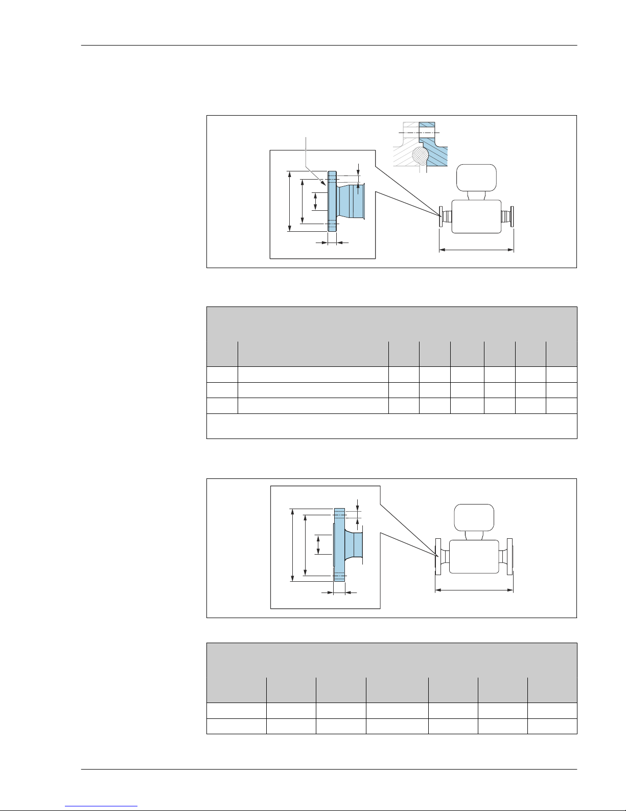
20 Detail X: Asymmetrical process connection; the part shown in gray is provided by the supplier.
Flange DIN 11864-2, aseptic female, Form A
1.4404 (316L)
Order code for "Process connection", option DES
DN
[mm]
Suitable for pipe EN 10357 (DIN 11850)
[mm]
A
[mm]B[mm]C[mm]D[mm]E[mm]L[mm]
2 to 8 13 × 1.5 (DN 10) 54 37 4 × ⌀9 10 10 183
15 19 × 1.5 (DN 15) 59 42 4 × ⌀9 10 16 183
25 29 × 1.5 (DN 25) 70 53 4 × ⌀9 10 26 183
Surface roughness: Ra ≤ 0.8 µm, optional ≤ 0.38 µm
Please note the internal diameters of the measuring tube and process connection (E) when cleaning with pigs.
Flanges with O-ring seal
C
D
A
B
E
L
A0015621
Flange according to EN 1092-1 (DIN 2501), Form B: PN 40
1.4404 (316L)
Order code for "Process connection", option D5S
DN
[mm]
A
[mm]
B
[mm]
C
[mm]
D
[mm]
E
[mm]
L
[mm]
2 to 8
1)
95 65 4 × ⌀14 16 17.3 198.4
15 95 65 4 × ⌀14 16 17.3 198.4
Page 38
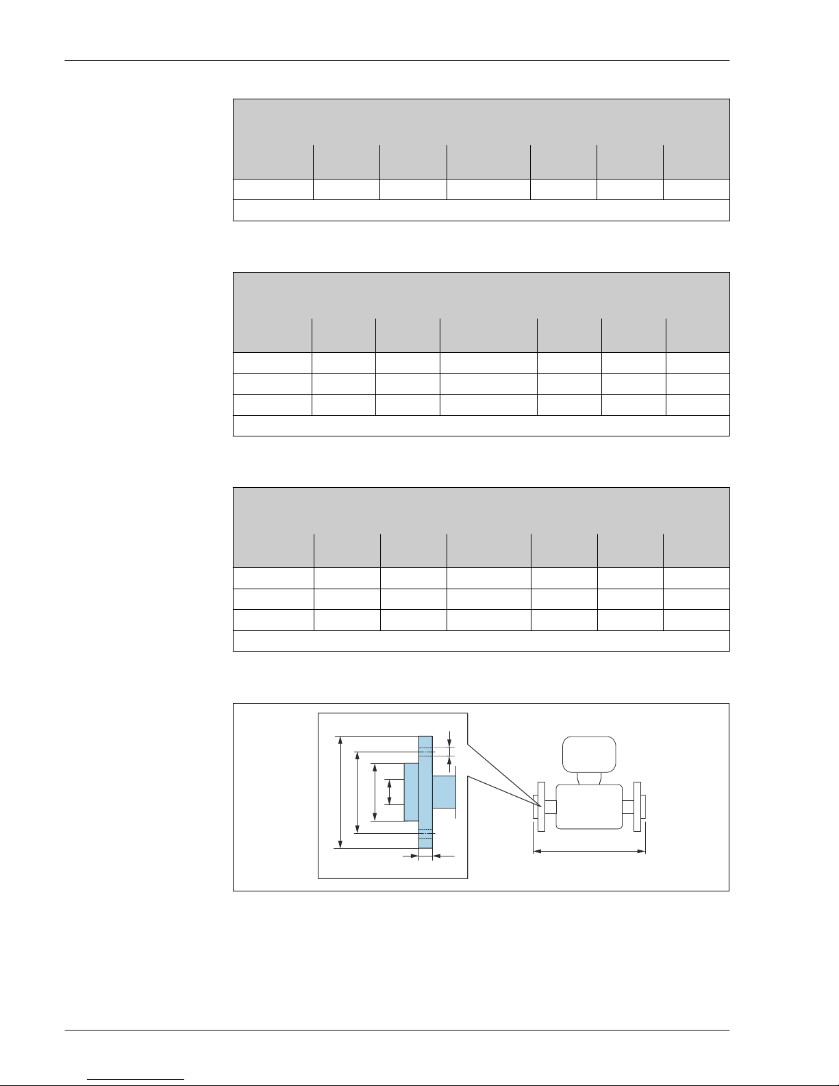
Proline Promag H 200
38 Endress+Hauser
Flange according to EN 1092-1 (DIN 2501), Form B: PN 40
1.4404 (316L)
Order code for "Process connection", option D5S
DN
[mm]
A
[mm]
B
[mm]
C
[mm]
D
[mm]
E
[mm]
L
[mm]
25 115 85 4 × ⌀14 18 28.5 198.4
Surface roughness: Ra ≤ 1.6 µm
1) DN 2 to 8 with DN 15 flanges as standard
Flange according to ASME B16.5: Class 150
1.4404 (316L)
Order code for "Process connection", option A1S
DN
[mm]
A
[mm]
B
[mm]
C
[mm]
D
[mm]
E
[mm]
L
[mm]
2 to 8
1)
90 60.3 4 × ⌀15.7 11.2 15.7 218
15 90 60.3 4 × ⌀15.7 11.2 15.7 218
25 110 79.4 4 × ⌀15.7 14.2 26.7 230
Surface roughness: Ra ≤ 1.6 µm
1) DN 2 to 8 with DN 15 flanges as standard
Flange according to JIS B2220: 20K
1.4404 (316L)
Order code for "Process connection", option N4S
DN
[mm]
A
[mm]
B
[mm]
C
[mm]
D
[mm]
E
[mm]
L
[mm]
2 to 8
1)
95 70 4 × ⌀15 14 15 220
15 95 70 4 × ⌀15 14 15 220
25 125 90 4 × ⌀19 16 25 220
Surface roughness: Ra ≤ 1.6 µm
1) DN 2 to 8 with DN 15 flanges as standard
L
C
D
A
B
F
E
A0022221
Page 39
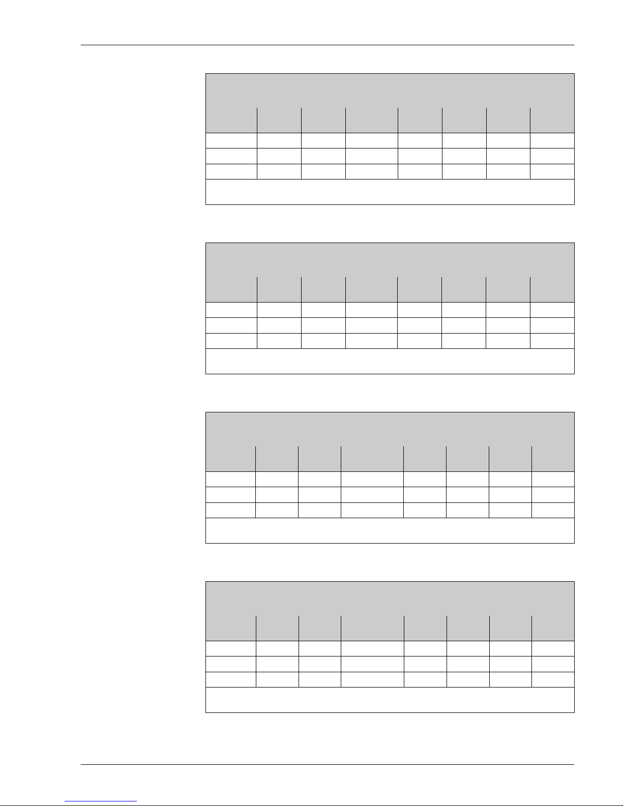
Proline Promag H 200
Endress+Hauser 39
Lap joint flange according to EN 1092-1 (DIN 2501): PN 16
PVDF
Order code for "Process connection", option D3P
DN
[mm]
A
[mm]
B
[mm]
C
[mm]
D
[mm]
E
[mm]
F
[mm]
L
[mm]
2 to 8
1)
95 65 4 x ⌀14 14.5 45 17.3 200
15 95 65 4 x ⌀14 14.5 45 17.3 200
25 115 85 4 x ⌀14 16.5 68 28.5 200
Surface roughness: Ra ≤ 1.6 µm
The required grounding rings can be ordered as accessories (order code: DK5HR-****).
1) DN 2 to 8 with DN 15 flanges as standard
Lap joint flange with grounding electrode according to EN 1092-1 (DIN 2501): PN 16
PVDF
Order code for "Process connection", option D4P
DN
[mm]
A
[mm]
B
[mm]
C
[mm]
D
[mm]
E
[mm]
F
[mm]
L
[mm]
2 to 8
1)
95 65 4 x ⌀14 14.5 45 17.3 200
15 95 65 4 x ⌀14 14.5 45 17.3 200
25 115 85 4 x ⌀14 16.5 68 28.5 200
Surface roughness: Ra ≤ 1.6 µm
Grounding rings are not necessary.
1) DN 2 to 8 with DN 15 flanges as standard
Lap joint flange according to ASME B16.5: Class 150
PVDF
Order code for "Process connection", option A1P
DN
[mm]
A
[mm]
B
[mm]
C
[mm]
D
[mm]
E
[mm]
F
[mm]
L
[mm]
2 to 8
1)
90 60.3 4 × ⌀ 15.7 15 35.1 15.7 200
15 90 60.3 4 × ⌀ 15.7 15 35.1 15.7 200
25 110 79.4 4 × ⌀ 15.7 16 50.8 26.7 200
Surface roughness: Ra ≤ 1.6 µm
The required grounding rings can be ordered as accessories (order code: DK5HR-****).
1) DN 2 to 8 with DN 15 flanges as standard
Lap joint flange with grounding electrode according to ASME B16.5: Class 150
PVDF
Order code for "Process connection", option A4P
DN
[mm]
A
[mm]
B
[mm]
C
[mm]
D
[mm]
E
[mm]
F
[mm]
L
[mm]
2 to 8
1)
90 60.3 4 × ⌀ 15.7 15 35.1 15.7 200
15 90 60.3 4 × ⌀ 15.7 15 35.1 15.7 200
25 110 79.4 4 × ⌀ 15.7 16 50.8 26.7 200
Surface roughness: Ra ≤ 1.6 µm
Grounding rings are not necessary.
1) DN 2 to 8 with DN 15 flanges as standard
Page 40
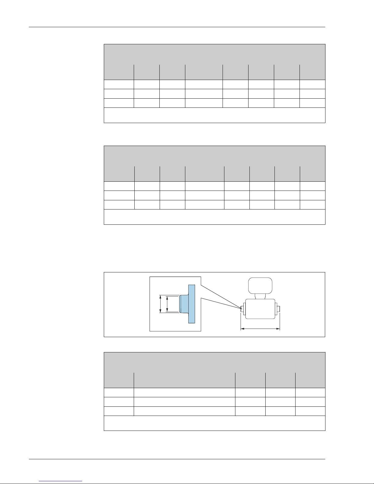
Proline Promag H 200
40 Endress+Hauser
Lap joint flange according to JIS B2220: 10K
PVDF
Order code for "Process connection", option N3P
DN
[mm]
A
[mm]
B
[mm]
C
[mm]
D
[mm]
E
[mm]
F
[mm]
L
[mm]
2 to 8
1)
95 70 4 × ⌀ 15.7 15 35.1 15 200
15 95 70 4 × ⌀ 15.7 15 35.1 15 200
25 125 90 4 × ⌀ 15.7 16 50.8 19 200
Surface roughness: Ra ≤ 1.6 µm
The required grounding rings can be ordered as accessories (order code: DK5HR-****).
1) DN 2 to 8 with DN 15 flanges as standard
Lap joint flange with grounding electrode according to JIS B2220: 10K
PVDF
Order code for "Process connection", option N4P
DN
[mm]
A
[mm]
B
[mm]
C
[mm]
D
[mm]
E
[mm]
F
[mm]
L
[mm]
2 to 8
1)
95 70 4 × ⌀ 15.7 15 35.1 15 200
15 95 70 4 × ⌀ 15.7 15 35.1 15 200
25 125 90 4 × ⌀ 15.7 16 50.8 19 200
Surface roughness: Ra ≤ 1.6 µm
Grounding rings are not necessary.
1) DN 2 to 8 with DN 15 flanges as standard
Welding nipple
Welding nipple with aseptic molded seal
L
A
B
A0027510
Welding nipple according to EN 10357 (DIN 11850)
1.4404 (316L)
Order code for "Process connection", option DAS
DN
[mm]
Suitable for pipe EN 10357 (DIN 11850)
[mm]
A
[mm]
B
[mm]
L
[mm]
2 to 8 13 × 1.5 13 10 132.6
15 19 × 1.5 19 16 132.6
25 29 × 1.5 29 26 132.6
Surface roughness: Ra ≤ 0.8 µm, optional ≤ 0.38 µm
Please note the internal diameters of the measuring tube and process connection (B) when cleaning with pigs.
Page 41
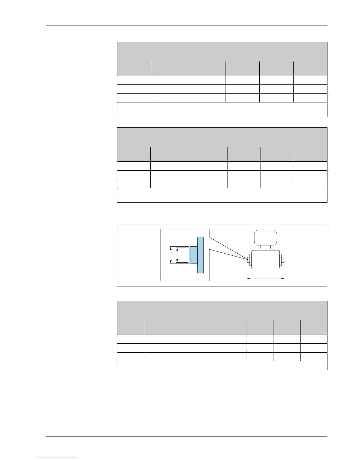
Proline Promag H 200
Endress+Hauser 41
Welding nipple according to ISO 2037
1.4404 (316L)
Order code for "Process connection", option IAS
DN
[mm]
Suitable for pipe ISO 2037
[mm]
A
[mm]
B
[mm]
L
[mm]
2 to 8 12.7 × 1.65 12 10 118.2
15 19.05 × 1.65 18 16 118.2
25 25.4 × 1.60 25 22.6 118.2
Surface roughness: Ra ≤ 0.8 µm, optional ≤ 0.38 µm
Please note the internal diameters of the measuring tube and process connection (B) when cleaning with pigs.
Welding nipple according to ASME BPE
1.4404 (316L)
Order code for "Process connection", option AAS
DN
[mm]
Suitable for pipe ASME BPE
[mm]
A
[mm]
B
[mm]
L
[mm]
2 to 8 12.7 × 1.65 12.7 9 118.2
15 19.1 × 1.65 19.1 16 118.2
25 25.4 × 1.65 25.4 22.6 118.2
Surface roughness: Ra ≤ 0.8 µm, optional ≤ 0.38 µm
Please note the internal diameters of the measuring tube and process connection (B) when cleaning with pigs.
Welding nipple with O-ring seal
L
A
B
A0027510
Welding nipple according to ODT/SMS
1.4404 (316L)
Order code for "Process connection", option A2S
DN
[mm]
Suitable for pipe ODT/SMS
[mm]
A
[mm]
B
[mm]
L
[mm]
2 to 8 13.5 × 2.30 13.5 9 126.6
15 21.3 × 2.65 21.3 16 126.6
25 33.7 × 3.25 33.7 27.2 126.6
Surface roughness: Ra ≤ 1.6 µm
Page 42
Proline Promag H 200
42 Endress+Hauser
Welding nipple according to DIN EN ISO 1127
1.4404 (316L)
Order code for "Process connection", option D1S
DN
[mm]
Suitable for pipe DIN EN ISO 1127
[mm]
A
[mm]
B
[mm]
L
[mm]
2 to 8 13.5 × 1.6 13.5 10.3 126.6
15 21.3 × 1.6 21.3 18.1 126.6
25 33.7 × 2.0 33.7 29.7 126.6
Surface roughness: Ra ≤ 1.6 µm
Welding nipple according to ISO 2037
1.4404 (316L)
Order code for "Process connection", option I1S
DN
[mm]
Suitable for pipe ISO 2037
[mm]
A
[mm]
B
[mm]
L
[mm]
2 to 8 13.5 × 2.3 13.5 9 126.6
15 21.3 × 2.65 21.3 16 126.6
25 33.7 × 3.25 33.7 27.2 126.6
Surface roughness: Ra ≤ 1.6 µm
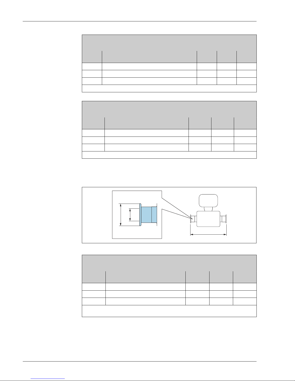
Clamp connections
Clamp connections with aseptic molded seal
L
A
B
A0015625
Clamp according to DIN 32676
1.4404 (316L)
Order code for "Process connection", option DBS
DN
[mm]
Suitable for pipe EN 10357 (DIN 11850)
[mm]
A
[mm]
B
[mm]
L
[mm]
2 to 8 14 × 2 (DN 10) 34 10 168
15 20 × 2 (DN 15) 34 16 168
25 30 × 2 (DN 25) 50.5 26 175
Surface roughness: Ra ≤ 0.8 µm, optional ≤ 0.38 µm
Please note the internal diameters of the measuring tube and process connection (B) when cleaning with pigs.
Page 43
Proline Promag H 200
Endress+Hauser 43
Tri-Clamp
1.4404 (316L)
Order code for "Process connection", option FAS
DN
[mm]
Suitable for pipe as per ASME BPE
[mm]
A
[mm]
B
[mm]
L
[mm]
2 to 8 12.7 × 1.65 25 9.4 143
15 19.1 × 1.65 25 15.8 143
25 25.4 × 1.65 50.4 22.1 143
Surface roughness: Ra ≤ 0.8 µm, optional ≤ 0.38 µm
Please note the internal diameters of the measuring tube and process connection (B) when cleaning with pigs.
Clamp according to ISO 2852, Fig. 2
1.4404 (316L)
Order code for "Process connection", option IBS
DN
[mm]
Suitable for pipe ISO 2037
[mm]
A
[mm]
B
[mm]
L
[mm]
25 24.5 × 1.65 50.5 22.6 174.6
Surface roughness: Ra ≤ 0.8 µm, optional ≤ 0.38 µm
Please note the internal diameters of the measuring tube and process connection (B) when cleaning with pigs.
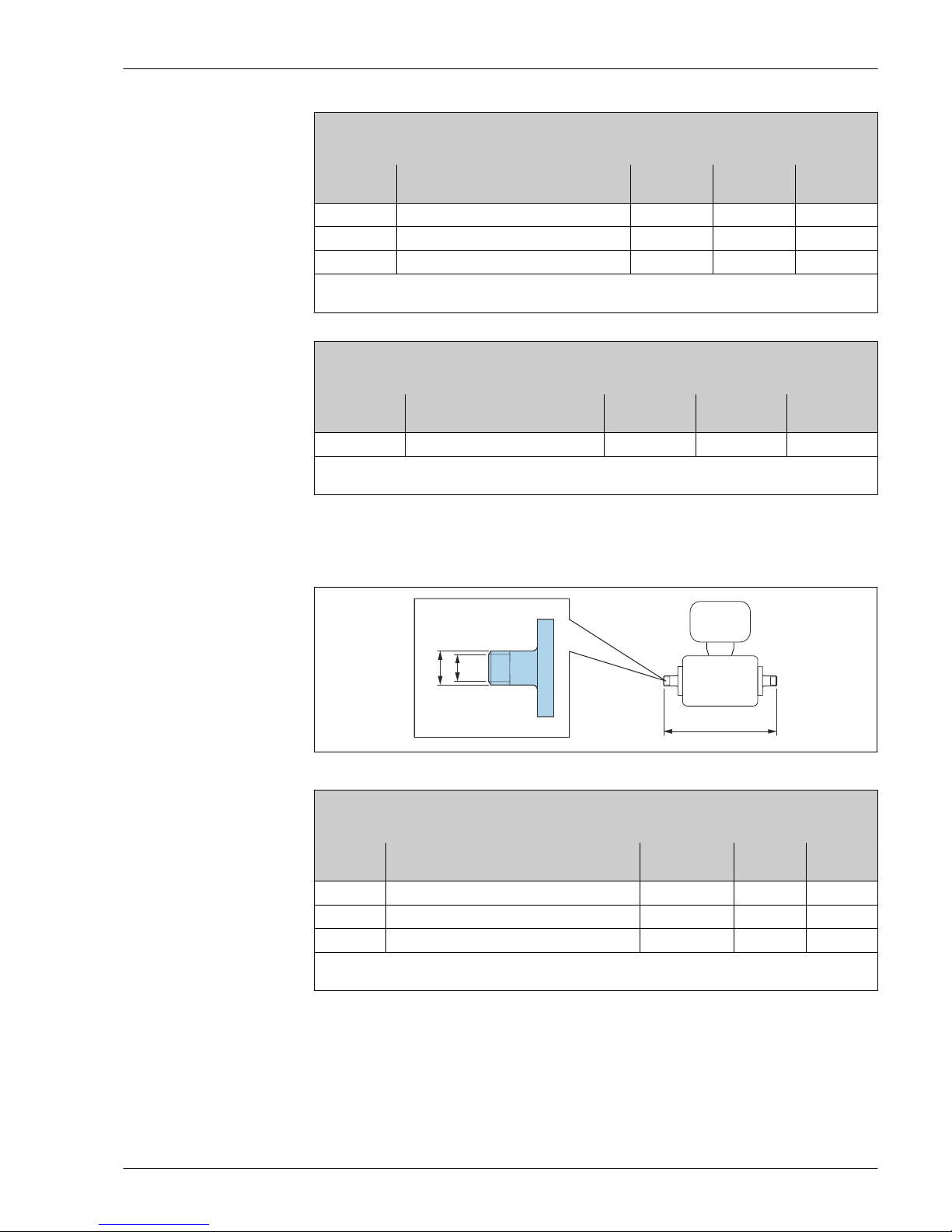
Cable glands
Threaded adapter with aseptic molded seal
L
A
B
A0027509
Coupling SC DIN 11851, threaded adapter
1.4404 (316L)
Order code for "Process connection", option DCS
DN
[mm]
Suitable for pipe EN 10357 (DIN 11850)
[mm]
A
[mm/in]
B
[mm]
L
[mm]
2 to 8 12 × 1 (DN 10) Rd 28 × ¹⁄₈ 10 174
15 18 × 1.5 (ODT ¾") Rd 34 × ¹⁄₈ 16 174
25 28 × 1 or 28×1.5 Rd 52 × ¹⁄₆ 26 190
Surface roughness: Ra ≤ 0.8 µm, optional ≤ 0.38 µm
Please note the internal diameters of the measuring tube and process connection (B) when cleaning with pigs.
Page 44
Proline Promag H 200
44 Endress+Hauser
Coupling DIN 11864-1, aseptic threaded hygienic connection, Form A
1.4404 (316L)
Order code for "Process connection", option DDS
DN
[mm]
Suitable for pipe EN 10357 (DIN 11850)
[mm]
A
[mm/in]
B
[mm]
L
[mm]
2 to 8 Pipe 13 × 1.5 (DN 10) Rd 28 × ¹⁄₈ 10 170
15 Pipe 19 × 1.5 Rd 34 × ¹⁄₈ 16 170
25 Pipe 29 × 1.5 Rd 52 × ¹⁄₆ 26 184
Surface roughness: Ra ≤ 0.8 µm, optional ≤ 0.38 µm
Please note the internal diameters of the measuring tube and process connection (B) when cleaning with pigs.
Coupling SMS 1145, threaded adapter
1.4404 (316L)
Order code for "Process connection", option SAS
DN
[mm]
Suitable for pipe ODT
[mm]
DN
SMS 1145
[mm]
A
[mm/in]
B
[mm]
L
[mm]
25 1 25 Rd40 × ¹⁄₆ 22.6 147.6
Surface roughness: Ra ≤ 0.8 µm, optional ≤ 0.38 µm
Please note the internal diameters of the measuring tube and process connection (B) when cleaning with pigs.
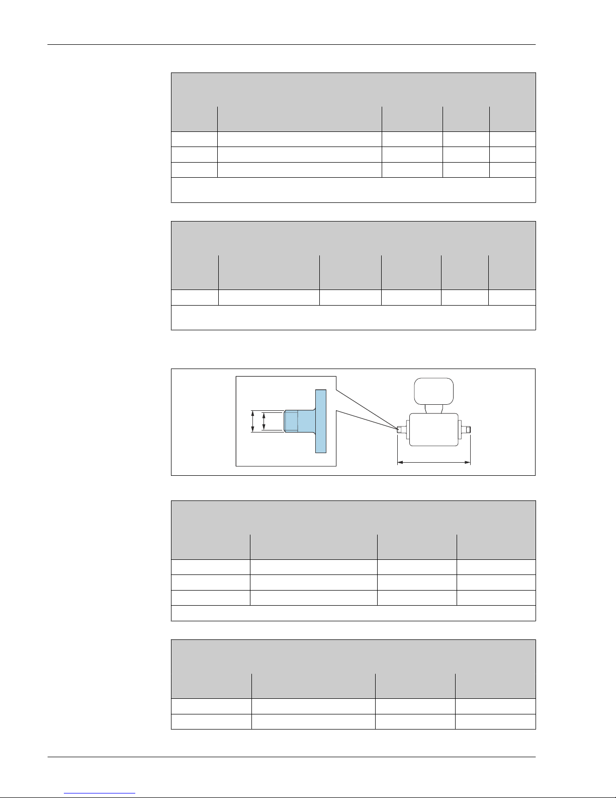
Threaded adapter with O-ring seal
L
A
B
A0027509
External thread according to ISO 228/DIN 2999
1.4404 (316L)
Order code for "Process connection", option I2S
DN
[mm]
A
[mm/in]
B
[mm]
L
[mm]
2 to 8 R 10.1 × 3/8 10 166
15 R 13.2 × ½ 16 166
25 R 16.5 × 1 25 170
Surface roughness: Ra ≤ 1.6 µm
Internal thread according to ISO 228/DIN 2999
1.4404 (316L)
Order code for "Process connection", option I3S
DN
[mm]
A
[mm/in]
B
[mm]
L
[mm]
2 to 8 Rp 13 × 3/8 9 176
15 Rp 14 × ½ 16 176
Page 45
Proline Promag H 200
Endress+Hauser 45
Internal thread according to ISO 228/DIN 2999
1.4404 (316L)
Order code for "Process connection", option I3S
DN
[mm]
A
[mm/in]
B
[mm]
L
[mm]
25 Rp 17 × 1 27.2 188
Surface roughness: Ra ≤ 1.6 µm
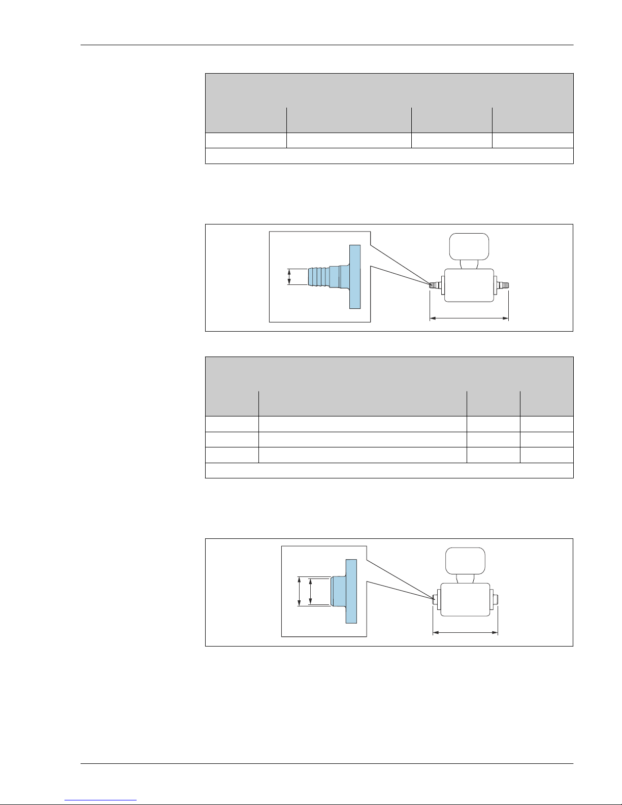
Hose adapter
Hose adapter with O-ring seal
L
A
A0027511
Hose adapter
1.4404 (316L)
Order code for "Process connection", options O1S, O2S, O3S
DN
[mm]
Suitable for internal diameter
[mm]
A
[mm]
L
[mm]
2 to 8 13 10 184
15 16 12.6 184
25 19 16 184
Surface roughness: Ra ≤ 1.6 µm
Adhesive sleeves
Adhesive sleeves with O-ring seal
L
A
B
A0027510
Page 46
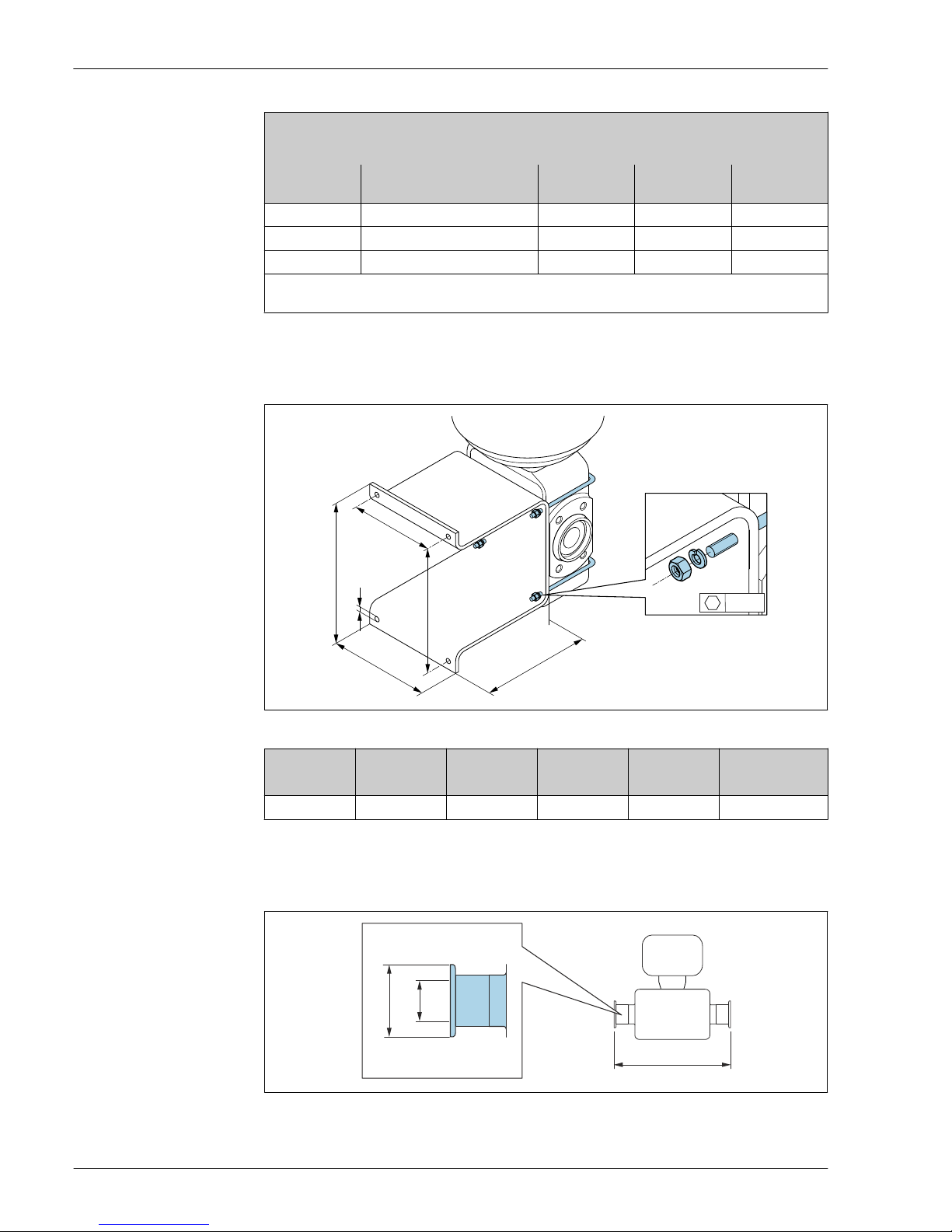
Proline Promag H 200
46 Endress+Hauser
Adhesive sleeve
PVC
Order code for "Process connection", options O1V, O2V
DN
[mm]
Suitable for pipe
[mm] / [in]
A
[mm]
B
[mm]
L
[mm]
2 to 8 20 × 2 (DIN 8062) 27 20.2 163
15 ½ 27.3 21.5 163
25 20 × 2 (DIN 8062) 27 20.2 142
Surface roughness: Ra ≤ 1.6 µm
The required grounding rings can be ordered as accessories (order code: DK5HR-****).
Mountings sets
Wall mounting kit
A
B
E
F
D
C
4 x
M5
A0005537
A B C Ø D E F
[mm] [mm] [mm] [mm] [mm] [mm]
137 110 120 7 125 88
Accessories
Clamp connections with aseptic molded seal available for order
L
A
B
A0015625
Page 47

Proline Promag H 200
Endress+Hauser 47
Tri-Clamp
1.4404 (316L)
Order code: DKH**-HF**
DN
[mm]
Suitable for pipe in accordance with ASME BPE (reduction)
[mm]
A
[mm]B[mm]L[mm]
15 Pipe ODT 1 50.4 22.1 143
Surface roughness: Ra ≤ 0.8 µm, optional ≤ 0.38 µm
Please note the internal diameters of the measuring tube and process connection (B) when cleaning with pigs.
Threaded glands with O-ring seal available for order
L
A
B
A0027509
External thread
1.4404 (316L)
Order code: DKH**-GD**
DN
[mm]
Suitable for NPT internal thread
[in]
A
[mm/in]
B
[mm]L[mm]
2 to 8 NPT 3/8 R 15.5 × 3/8 10 186
15 NPT ½ R 20 × ½ 16 186
25 NPT 1 R 25 × 1 25 196
Surface roughness: Ra ≤ 1.6 µm
Internal thread
1.4404 (316L)
Order code: DKH**-GC**
DN
[mm]
Suitable for NPT external thread
[in]
A
[mm/in]
B
[mm]
L
[mm]
2 to 8 NPT 3/8 R 13 × 3/8 8.9 176
15 NPT ½ R 14 × ½ 16 176
25 NPT 1 R 17 × 1 27.2 188
Surface roughness: Ra ≤ 1.6 µm
Page 48
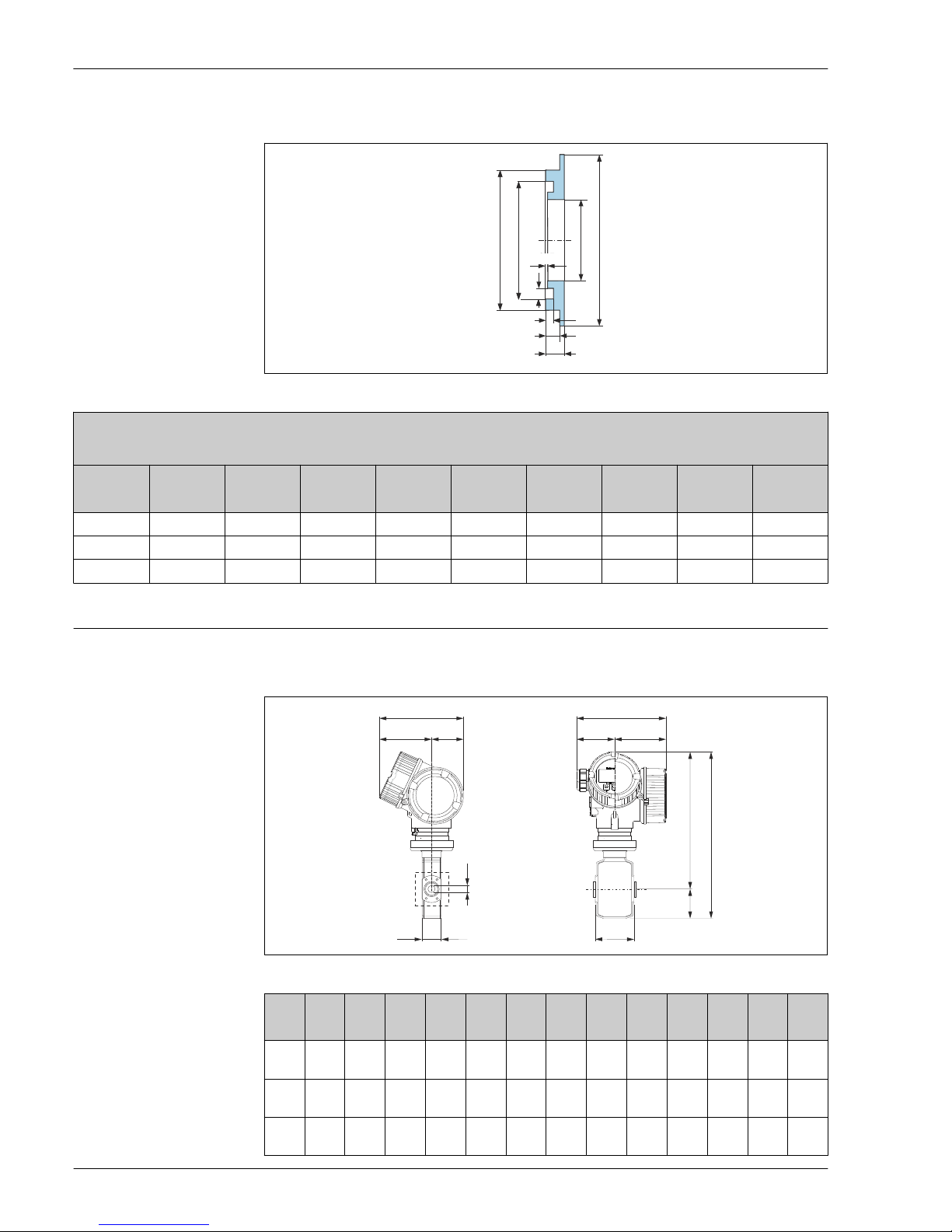
Proline Promag H 200
48 Endress+Hauser
Grounding rings
Ø C
Ø di
Ø B
Ø D
0.5
E
F
G
H
J
A0017673
For lap joint flange made of PVDF and PVC adhesive sleeve
1.4435 (316L), Alloy C22, tantalum
Order code: DK5HR-****
DN di B C D E F G H J
[mm] [mm] [mm] [mm] [mm] [mm] [mm] [mm] [mm] [mm]
2 to 8 9 22 17.6 33.9 0.5 3.5 1.9 3.4 4.5
15 16 29 24.6 33.9 0.5 3.5 1.9 3.4 4.5
25 26 39 34.6 43.9 0.5 3.5 1.9 3.4 4.5
Dimensions in US units Compact version
Order code for "Housing", option C "GT20 dual compartment, aluminum coated"
G
di
Q
C
A
B
J
H
K
FE
D
L
A0017653
DN A B
1)
C D
2)
E F G H
3)
J K L
4)
Q di
[in] [in] [in] [in] [in] [in] [in] [in] [in] [in] [in] [in] [mm] [in]
1/12 6.38 4.02 2.36 6.50 2.95 3.54 1.69 10.39 1.88 12.27 3.39
4 ×
M6
0.09
5/32 6.38 4.02 2.36 6.50 2.95 3.54 1.69 10.39 1.88 12.27 3.39
4 ×
M6
0.18
5/16 6.38 4.02 2.36 6.50 2.95 3.54 1.69 10.39 1.88 12.27 3.39
4 ×
M6
0.35
Page 49
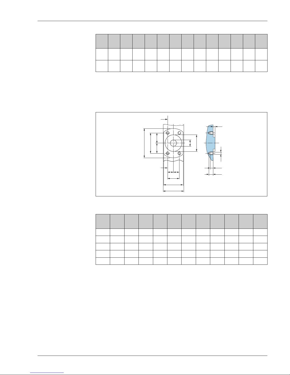
Proline Promag H 200
Endress+Hauser 49
DN A B
1)
C D
2)
E F G H
3)
J K L
4)
Q di
[in] [in] [in] [in] [in] [in] [in] [in] [in] [in] [in] [in] [mm] [in]
½ 6.38 4.02 2.36 6.50 2.95 3.54 1.69 10.39 1.88 12.27 3.39
4 ×
M6
0.63
1 6.38 4.02 2.36 6.50 2.95 3.54 2.07 10.55 2.04 12.59 3.39
4 ×
M6
1.02
1) For version without local display: values - 0.28 in
2) For version with overvoltage protection (OVP): values + 0.31 in
3) For version without local display: values - 0.39 in
4) Total length (L) depends on the process connections.
Sensor flange connection
G
F
K
H
E
Z
Z Z-Z
L
A
B
D
M
C
B/2
B/2
E
–
2
E
–
2
A0017657
21 Front view without process connections
DN A B C D E F G H K L M
[in] [in] [in] [in] [in] [in] [in] [in] [in] [in] [in] [mm]
1/12 2.44 1.64 1.34 0.35 0.94 1.65 1.69 0.33 0.24 0.16 M6
5/32 2.44 1.64 1.34 0.35 0.94 1.65 1.69 0.33 0.24 0.16 M6
5/16 2.44 1.64 1.34 0.35 0.94 1.65 1.69 0.33 0.24 0.16 M6
½ 2.44 1.64 1.34 0.63 0.94 1.65 1.69 0.33 0.24 0.16 M6
1 2.83 1.98 1.73 0.89 1.14 2.17 2.20 0.33 0.24 0.16 M6
Page 50
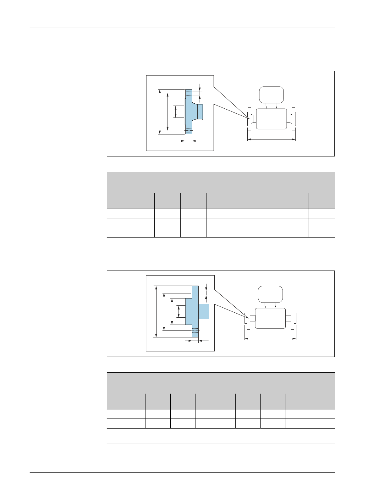
Proline Promag H 200
50 Endress+Hauser
Flanges
Flanges with O-ring seal
C
D
A
B
E
L
A0015621
Flange according to ASME B16.5: Class 150
1.4404 (316L)
Order code for "Process connection", option A1S
DN
[in]
A
[in]
B
[in]
C
[in]
D
[in]
E
[in]
L
[in]
¹⁄₁₂ to ³⁄₈
1)
3.50 2.38 4 × ⌀ 0.62 0.44 0.62 8.59
½ 3.50 2.38 4 × ⌀ 0.62 0.44 0.63 8.59
1 4.25 3.12 4 × ⌀ 0.62 0.56 1.05 9.05
Surface roughness: Ra ≤ 63 µin
1) DN ¹⁄₁₂ to ³⁄₈ with DN ½" flanges as standard
L
C
D
A
B
F
E
A0022221
Lap joint flange according to ASME B16.5: Class 150
PVDF
Order code for "Process connection", option A1P
DN
[in]
A
[in]
B
[in]
C
[in]
D
[in]
E
[in]
F
[in]
L
[in]
¹⁄₁₂ to ³⁄₈
1)
3.74 2.36 4 × ⌀ 0.62 0.59 1.38 0.63 7.87
½ 3.74 2.36 4 × ⌀ 0.62 0.59 1.38 0.63 7.87
Surface roughness: Ra ≤ 63 µin
The required grounding rings can be ordered as accessories (order code: DK5HR-****).
1) DN ¹⁄₁₂ to ³⁄₈ with DN ½" flanges as standard
Page 51
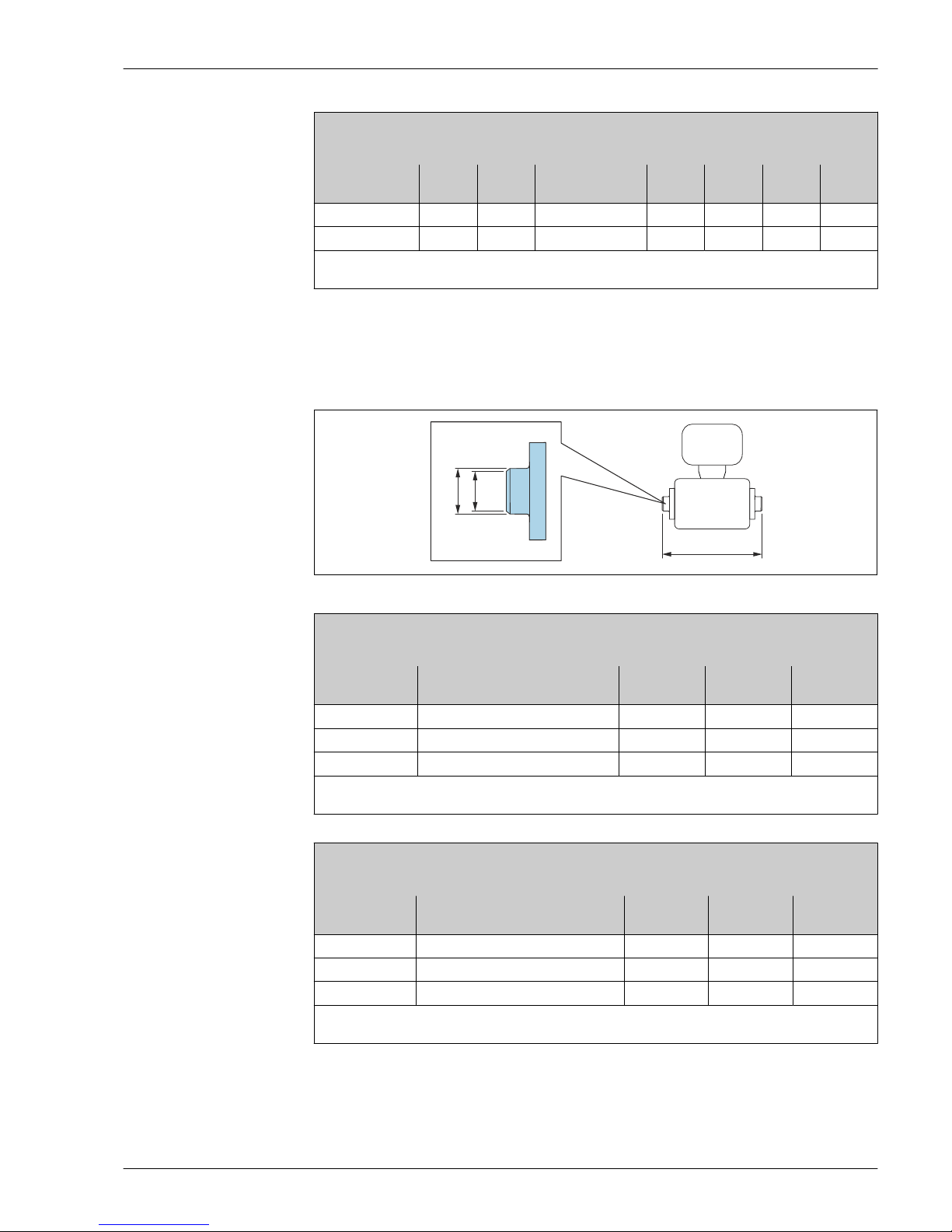
Proline Promag H 200
Endress+Hauser 51
Lap joint flange according to ASME B16.5: Class 150
PVDF
Order code for "Process connection", option A4P
DN
[in]
A
[in]
B
[in]
C
[in]
D
[in]
E
[in]
F
[in]
L
[in]
¹⁄₁₂ to ³⁄₈
1)
3.74 2.36 4 × ⌀ 0.62 0.59 1.38 0.63 7.87
½ 3.74 2.36 4 × ⌀ 0.62 0.59 1.38 0.63 7.87
Surface roughness: Ra ≤ 63 µin
Grounding rings are not necessary.
1) DN ¹⁄₁₂ to ³⁄₈ with DN ½" flanges as standard
Welding nipple
Welding nipple with aseptic molded seal
L
A
B
A0027510
Welding nipple according to ISO 2037
1.4404 (316L)
Order code for "Process connection", option IAS
DN
[in]
Suitable for pipe ISO 2037
[in]
A
[in]
B
[in]
L
[in]
¹⁄₁₂ to ³⁄₈ 0.50 × 0.06 0.47 0.39 4.65
½ 0.75 × 0.06 0.71 0.63 4.65
1 1.00 × 0.06 0.98 0.89 4.65
Surface roughness: Ra ≤ 31.5 µin, optional ≤ 15 µin
Please note the internal diameters of the measuring tube and process connection (B) when cleaning with pigs.
Welding nipple according to ASME BPE
1.4404 (316L)
Order code for "Process connection", option AAS
DN
[in]
Suitable for pipe ASME BPE
[in]
A
[in]
B
[in]
L
[in]
¹⁄₁₂ to ³⁄₈ 0.50 × 0.06 0.50 0.35 4.65
½ 0.75 × 0.06 0.75 0.63 4.65
1 1.00 × 0.06 1.00 0.89 4.65
Surface roughness: Ra ≤ 31.5 µin, optional ≤ 15 µin
Please note the internal diameters of the measuring tube and process connection (B) when cleaning with pigs.
Page 52
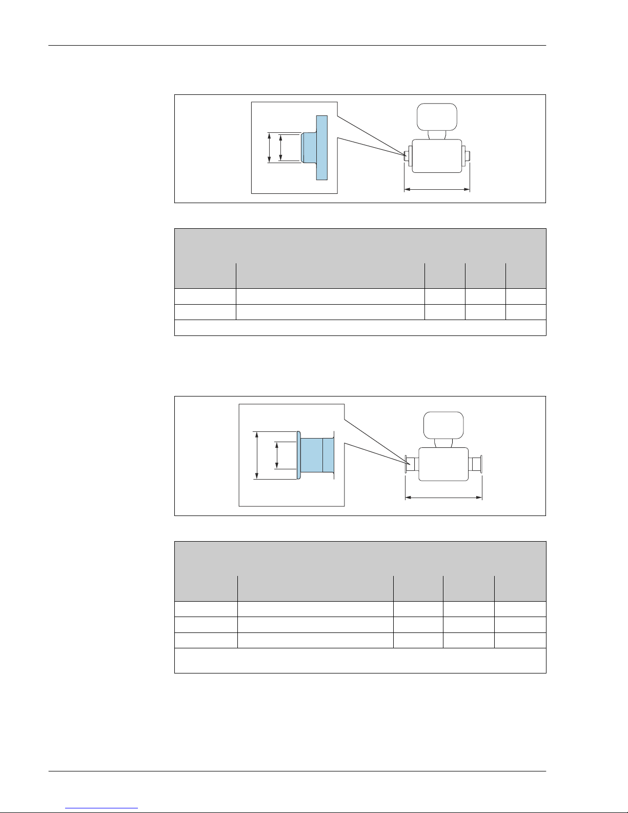
Proline Promag H 200
52 Endress+Hauser
Welding nipple with O-ring seal
L
A
B
A0027510
Welding nipple according to ODT/SMS
1.4404 (316L)
Order code for "Process connection", option A2S
DN
[in]
Suitable for pipe ODT/SMS
[in]
A
[in]
B
[in]
L
[in]
¹⁄₁₂ to ³⁄₈ 0.53 × 0.09 0.53 0.35 4.99
½ 0.84 × 0.10 0.84 0.63 4.99
Surface roughness: Ra ≤ 63 µin
Clamp connections
Clamp connections with aseptic molded seal
L
A
B
A0015625
Tri-Clamp
1.4404 (316L)
Order code for "Process connection", option FAS
DN
[in]
Suitable for pipe as per ASME BPE
[in]
A
[in]
B
[in]
L
[in]
¹⁄₁₂ to ³⁄₈ ½ 1 0.37 5.63
½ ¾ 25 0.62 5.63
1 1 2 0.87 5.63
Surface roughness: Ra ≤ 31.5 µin, optional ≤ 15 µin
Please note the internal diameters of the measuring tube and process connection (B) when cleaning with pigs.
Page 53
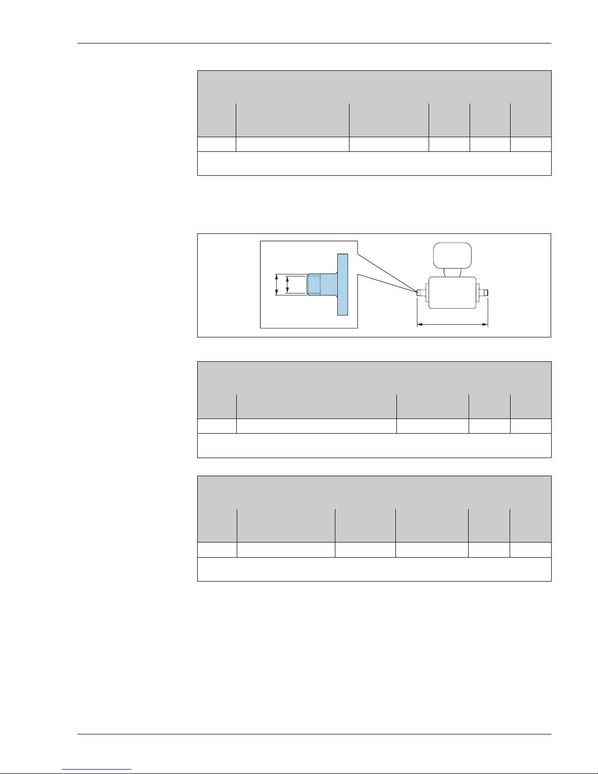
Proline Promag H 200
Endress+Hauser 53
Clamp according to ISO 2852, Fig. 2
1.4404 (316L)
Order code for "Process connection", option IBS
DN
[in]
Suitable for pipe ISO 2037
[in]
DN
Clamp ISO 2852
[in]
A
[in]
B
[in]
L
[in]
1 0.96 × 0.06 1 2.00 0.89 6.87
Surface roughness: Ra ≤ 31.5 µin, optional ≤ 15 µin
Please note the internal diameters of the measuring tube and process connection (B) when cleaning with pigs.
Cable glands
Threaded adapter with aseptic molded seal
L
A
B
A0027509
Coupling SC DIN 11851, threaded adapter
1.4404 (316L)
Order code for "Process connection", option DCS
DN
[in]
Suitable for pipe EN 10357 (DIN 11850)
[in]
A
[in]
B
[in]
L
[in]
½ Pipe ODT ¾ Rd0.05 × 0.13 0.63 6.85
Surface roughness: Ra ≤ 31.5 µin, optional ≤ 15 µin
Please note the internal diameters of the measuring tube and process connection (B) when cleaning with pigs.
Coupling SMS 1145, threaded adapter
1.4404 (316L)
Order code for "Process connection", option SAS
DN
[in]
Suitable for pipe ODT
[in]
DN
SMS 1145
[in]
A
[in]
B
[in]
L
[in]
1 1 1 Rd1.57 × 0.17 0.89 5.81
Surface roughness: Ra ≤ 31.5 µin, optional ≤ 15 µin
Please note the internal diameters of the measuring tube and process connection (B) when cleaning with pigs.
Page 54
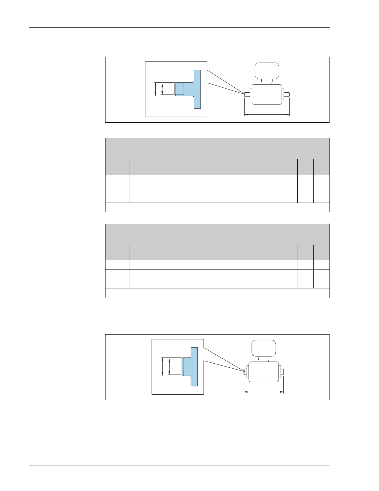
Proline Promag H 200
54 Endress+Hauser
Threaded adapter with O-ring seal
L
A
B
A0027509
External thread according to ISO 228/DIN 2999
1.4404 (316L)
Order code for "Process connection", option I2S
DN
[in]
Suitable for internal thread ISO 228 / DIN 2999
[in]
A
[in]
B
[in]L[in]
¹⁄₁₂ to ³⁄₈ R 3/8 Rd 0.40 × 3/8 0.39 6.53
½ R ½ Rd 0.52 × ½ 0.63 6.53
1 R 1 Rd 0.66 × 1 0.98 6.69
Surface roughness: Ra ≤ 63 µin
Internal thread according to ISO 228/DIN 2999
1.4404 (316L)
Order code for "Process connection", option I3S
DN
[in]
Suitable for external thread ISO 228 / DIN 2999
[in]
A
[in]
B
[in]L[in]
¹⁄₁₂ to ³⁄₈ Rp 3/8 Rd 0.51 × 3/8 0.35 6.93
½ Rp ½ Rd 0.55 × ½ 0.63 6.93
1 Rp 1 Rd 0.67 × 1 1.07 7.41
Surface roughness: Ra ≤ 63 µin
Adhesive sleeves
Adhesive sleeves with O-ring seal
L
A
B
A0027510
Page 55
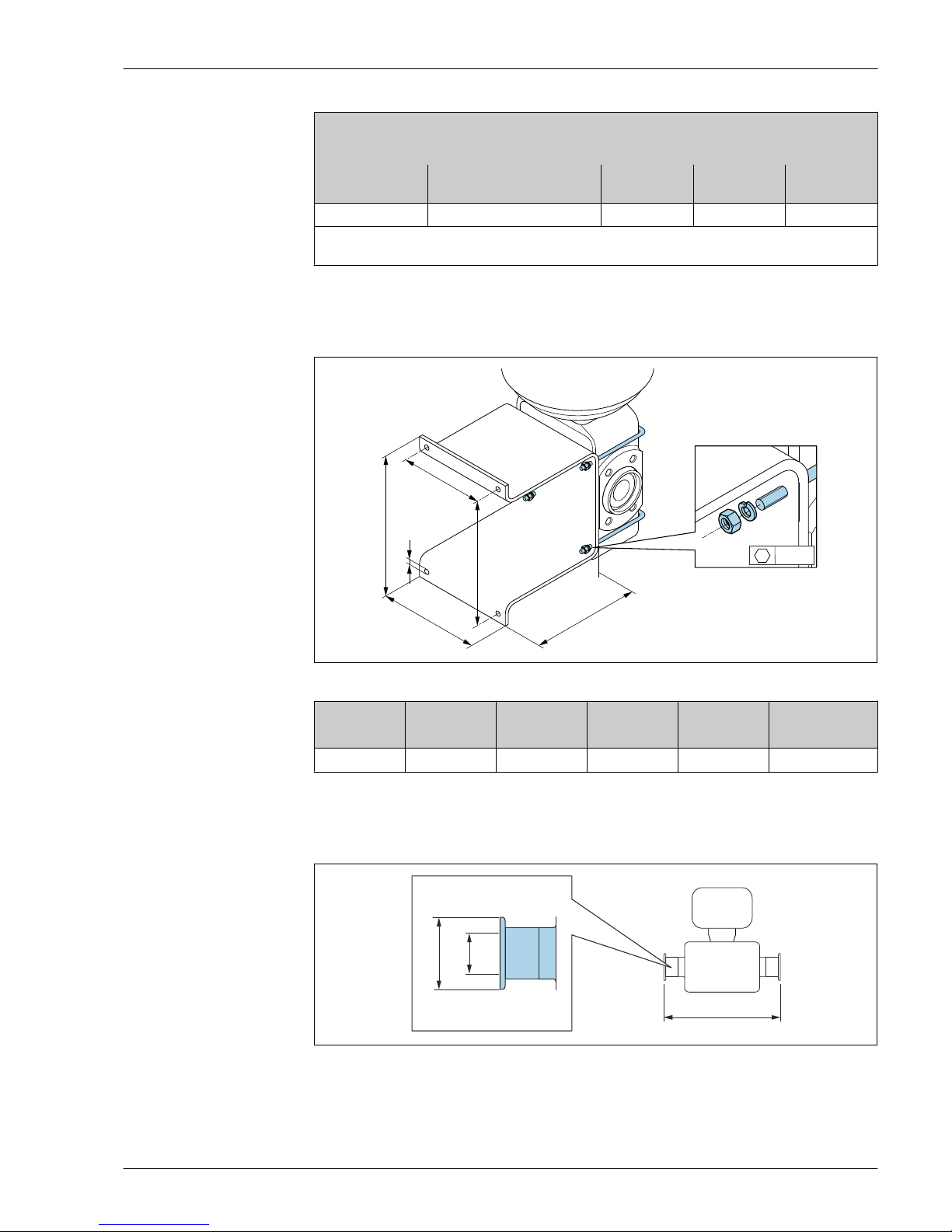
Proline Promag H 200
Endress+Hauser 55
Adhesive sleeve
PVC
Order code for "Process connection", options O1V, O2V
DN
[in]
Suitable for pipe
[in]
A
[in]
B
[in]
L
[in]
¹⁄₁₂ to ³⁄₈ ½ 1.07 0.85 6.43
Surface roughness: Ra ≤ 63 µin
The required grounding rings can be ordered as accessories (order code: DK5HR-****).
Mountings sets
Wall mounting kit
A
B
E
F
D
C
4 x
M5
A0005537
A B C Ø D E F
[in] [in] [in] [in] [in] [in]
5.39 4.33 4.72 0.28 4.92 3.46
Accessories
Clamp connections with aseptic molded seal available for order
L
A
B
A0015625
22 Hygienic clamp adapter connection suitable for pipes with connection according to ASME BPE (reduction)
Page 56
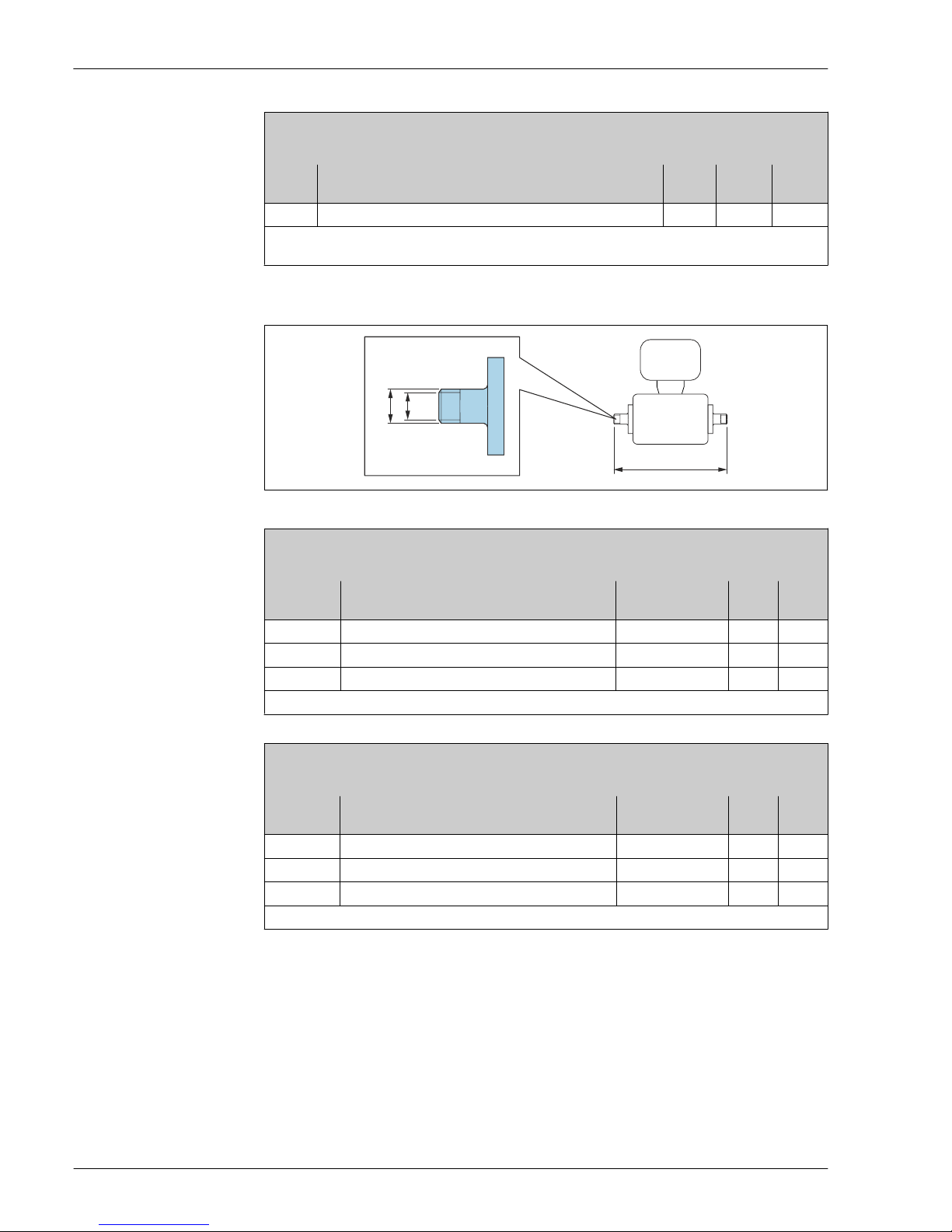
Proline Promag H 200
56 Endress+Hauser
Tri-Clamp
1.4404 (316L)
Order code: DKH**-HF**
DN
[in]
Suitable for pipe in accordance with ASME BPE (reduction)
[in]
A
[in]
B
[in]
L
[in]
½ Pipe ODT 1 2 0.87 5.63
Surface roughness: Ra ≤ 31.5 µin, optional ≤ 15 µin
Please note the internal diameters of the measuring tube and process connection (B) when cleaning with pigs.
Threaded glands with O-ring seal available for order
L
A
B
A0027509
External thread
1.4404 (316L)
Order code: DKH**-GD**
DN
[in]
Suitable for NPT internal thread
[in]
A
[in]
B
[in]L[in]
¹⁄₁₂ to ³⁄₈ NPT 3/8 R 0.61 × 3/8 0.39 7.39
½ NPT ½ R 0.79 × ½ 0.63 7.39
1 NPT 1 R 1 × 1 1.00 7.73
Surface roughness: Ra ≤ 63 µin
Internal thread
1.4404 (316L)
Order code: DKH**-GC**
DN
[in]
Suitable for NPT external thread
[in]
A
[in]
B
[in]L[in]
¹⁄₁₂ to ³⁄₈ NPT 3/8 R 0.51 × 3/8 0.35 6.93
½ NPT ½ R 0.55 × ½ 0.63 6.93
1 NPT 1 R 0.67 × 1 1.07 7.41
Surface roughness: Ra ≤ 63 µin
Page 57
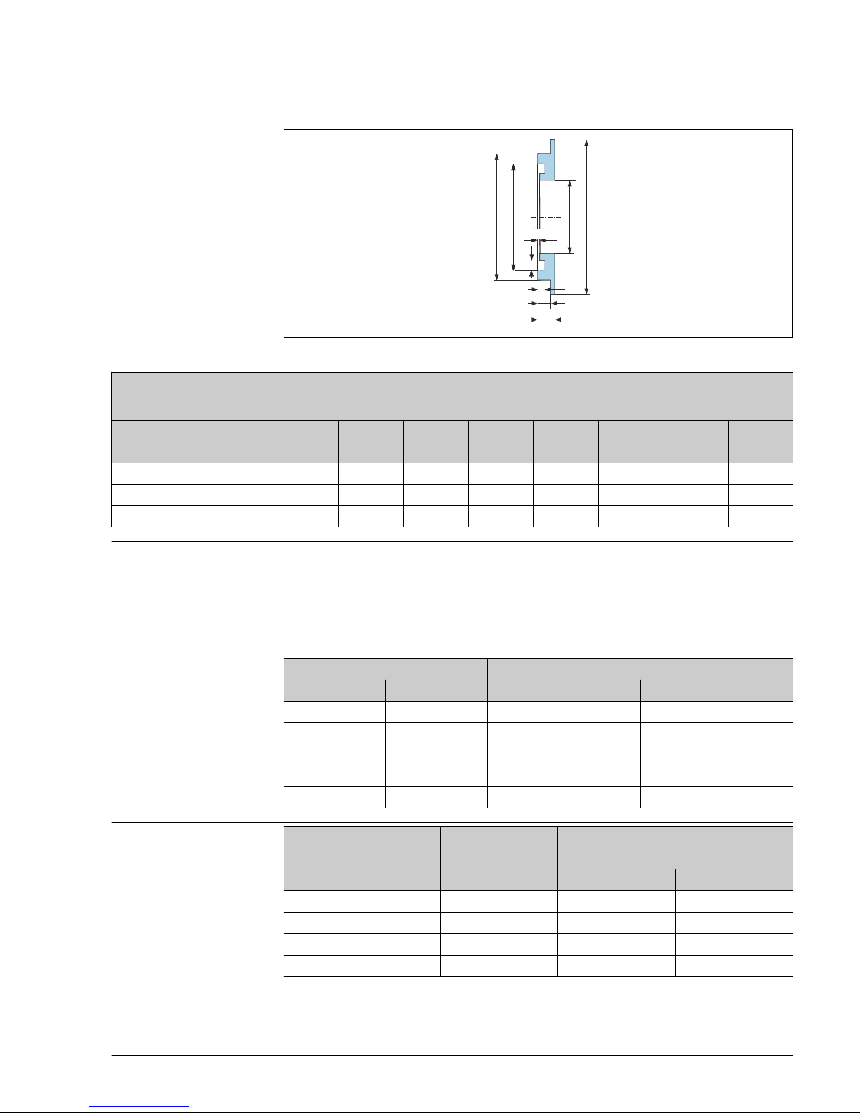
Proline Promag H 200
Endress+Hauser 57
Grounding rings
Ø C
Ø di
Ø B
Ø D
0.5
E
F
G
H
J
A0017673
For lap joint flange made of PVDF and PVC adhesive sleeve
1.4435 (316L), Alloy C22, tantalum
Order code: DK5HR-****
DN di B C D E F G H J
[in] [in] [in] [in] [in] [in] [in] [in] [in] [in]
¹⁄₁₂ to ³⁄₈ 0.35 0.87 0.69 1.33 0.02 0.14 0.07 0.13 0.18
½ 0.63 1.14 0.97 1.33 0.02 0.14 0.07 0.13 0.18
1 0.89 1.44 1.23 1.73 0.02 0.14 0.07 0.13 0.18
Weight
All values (weight exclusive of packaging material) refer to devices for standard pressure ratings.
Different values due to different transmitter versions:
Compact version
• Including the transmitter (1.9 kg (4.2 lbs))
• Weight specifications apply to standard pressure ratings and without packaging material.
Nominal diameter Weight
[mm] [in] [kg] [lbs]
2 ¹⁄₁₂ 3.7 8.2
4 ⁵⁄₃₂ 3.7 8.2
8 ⁵⁄₁₆ 3.8 8.4
15 ¹⁄₂ 3.9 8.6
25 1 4.0 8.8
Measuring tube specification
Nominal diameter Pressure rating
1)
Process connection internal diameter
EN (DIN) PFA
[mm] [in] [bar] [mm] [in]
2 1/12 PN 16/40 2.25 0.09
4 5/32 PN 16/40 4.5 0.18
8 5/16 PN 16/40 9.0 0.35
15 ½ PN 16/40 16.0 0.63
Page 58
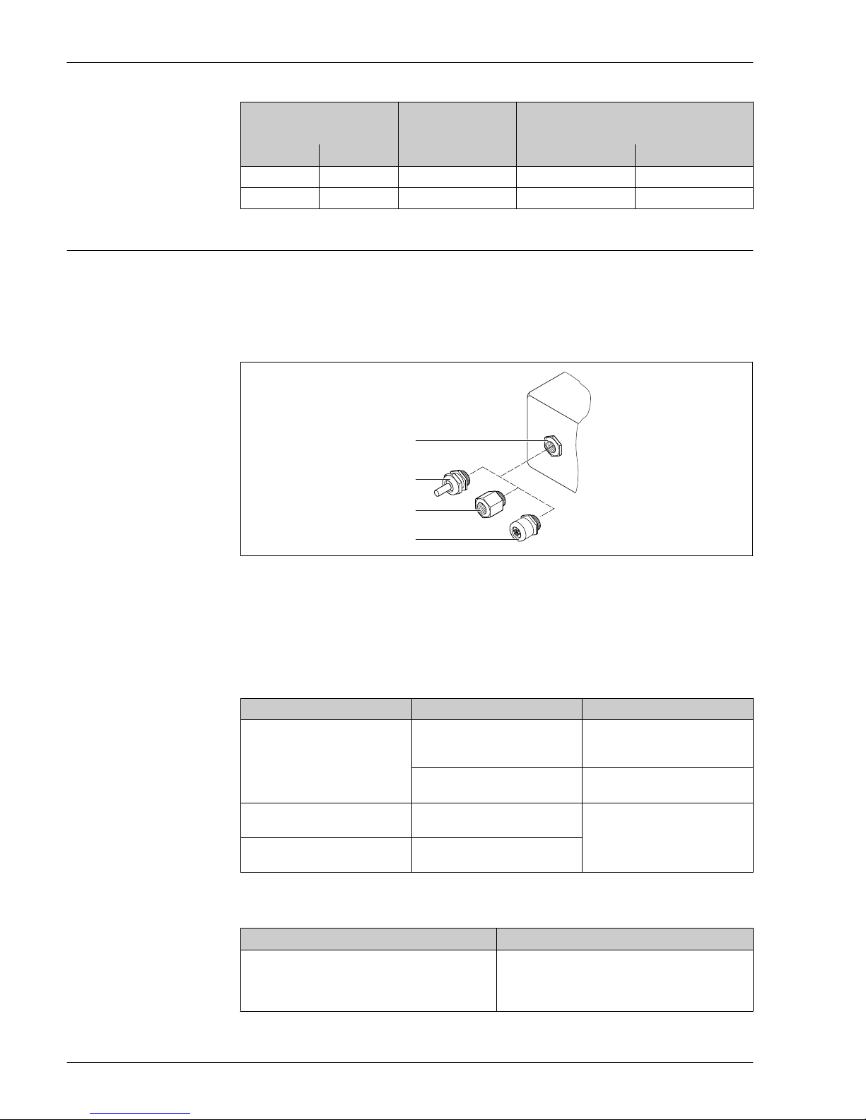
Proline Promag H 200
58 Endress+Hauser
Nominal diameter Pressure rating
1)
Process connection internal diameter
EN (DIN) PFA
[mm] [in] [bar] [mm] [in]
– 1 PN 16/40 22.6 0.89
25 – PN 16/40 26.0 1.02
1) Depending on process connection and seals used
Materials Transmitter housing
• Order code for "Housing", option C "Compact, aluminum coated":
Aluminum, AlSi10Mg, coated
• Window material: glass
Cable entries/cable glands
1
2
3
4
A0028352
23 Possible cable entries/cable glands
1 Female thread M20 × 1.5
2 Cable gland M20 × 1.5
3 Adapter for cable entry with internal thread G ½" or NPT ½"
4 Device plug connectors
Order code for "Housing", option C "GT20 dual compartment, aluminum coated"
Cable entry/cable gland Type of protection Material
Cable gland M20 × 1.5 • Non-Ex
• Ex ia
• Ex ic
Plastic
Adapter for cable entry with
internal thread G ½"
Nickel-plated brass
Adapter for cable entry with
internal thread NPT ½"
For non-Ex and Ex
(except for CSA Ex d/XP)
Nickel-plated brass
Thread NPT ½"
via adapter
For non-Ex and Ex
Device plug
Electrical connection Material
Plug M12x1 • Socket: stainless steel, 1.4401/316
• Contact housing: plastic, PUR, black
• Contacts: metal, CuZn, gold-plated
• Threaded connection seal: NBR
Page 59

Proline Promag H 200
Endress+Hauser 59
Sensor housing
Stainless steel 1.4301 (304)
Measuring tubes
Stainless steel 1.4301 (304)
Liner
PFA (USP Class VI, FDA 21 CFR 177.1550, 3A)
Process connections
• Stainless steel, 1.4404 (F316L)
• PVDF
• PVC adhesive sleeve
Electrodes
• Standard: 1.4435 (316L)
• Optional: Alloy C22, tantalum, platinum
Seals
• O-ring seal: EPDM, FKM, Kalrez
• Aseptic molded seal: EPDM
1)
, FKM, silicone
1)
Accessories
Protective cover
Stainless steel, 1.4404 (316L)
Grounding rings
• Standard: 1.4435 (316L)
• Optional: Alloy C22, tantalum
Wall mounting kit
Stainless steel 1.4301 (304)
Fitted electrodes
Measuring electrodes and empty pipe detection electrodes (only DN 25 (1")):
1.4435 (316L), Alloy C22, platinum, tantalum
Process connections
With O-ring seal:
• Welding nipple (DIN EN ISO 1127, ODT/SMS, ISO 2037)
• Flange (EN (DIN), ASME, JIS)
• Flange from PVDF (EN (DIN), ASME, JIS)
• External thread
• Internal thread
• Hose connection
• PVC adhesive sleeve
With aseptic molded seal:
• Welding nipple (EN 10357 (DIN 11850), ODT/SMS, ISO 2037)
• Clamp (ISO 2852, DIN 32676, L14 AM7)
• Coupling (DIN 11851, DIN 11864-1, ISO 2853, SMS 1145)
• Flange DIN 11864-2
For information on the different materials used in the process connections → 59
Surface roughness
Stainless steel electrodes, 1.4435 (316L); Alloy C22, 2.4602 (UNS N06022); platinum; tantalum:
≤ 0.3 to 0.5 µm (11.8 to 19.7 µin)
(All data relate to parts in contact with fluid)
1) USP Class VI, FDA 21 CFR 177.2600, 3A
Page 60
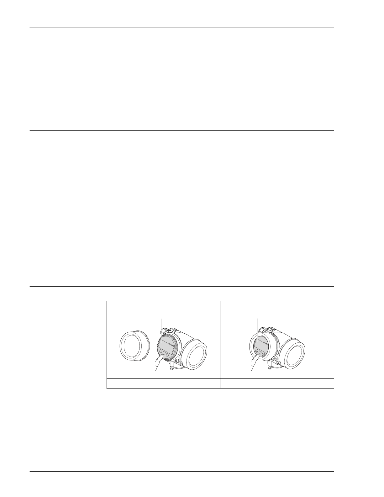
Proline Promag H 200
60 Endress+Hauser
Liner with PFA:
≤ 0.4 µm (15.7 µin)
(All data relate to parts in contact with fluid)
Stainless steel process connections:
• With O-ring seal: ≤ 1.6 µm (63 µin)
• With aseptic seal: ≤ 0.8 µm (31.5 µin)
(All data relate to parts in contact with fluid)
Operability
Operating concept
Operator-oriented menu structure for user-specific tasks
• Commissioning
• Operation
• Diagnostics
• Expert level
Quick and safe commissioning
• Guided menus ("Make-it-run" wizards) for applications
• Menu guidance with brief explanations of the individual parameter functions
Reliable operation
• Operation in the following languages:
– Via local display:
English, German, French, Spanish, Italian, Dutch, Portuguese, Polish, Russian, Swedish, Turkish,
Chinese, Japanese, Bahasa (Indonesian), Vietnamese, Czech
– Via "FieldCare" operating tool:
English, German, French, Spanish, Italian, Chinese, Japanese
• Uniform operating philosophy applied to device and operating tools
• If replacing the electronic module, transfer the device configuration via the integrated memory
(integrated HistoROM) which contains the process and measuring device data and the event
logbook. No need to reconfigure.
Efficient diagnostics increase measurement availability
• Troubleshooting measures can be called up via the device and in the operating tools
• Diverse simulation options, logbook for events that occur and optional line recorder functions
Local operation Via display module
Order code for "Display; Operation", option C "SD02" Order code for "Display; Operation", option E "SD03"
+
E
–
1
A0015544
1
+
E
–
A0015546
1 Operation with pushbuttons 1 Operation with touch control
Display elements
• 4-line display
• With order code for "Display; operation", option E:
White background lighting; switches to red in event of device errors
• Format for displaying measured variables and status variables can be individually configured
• Permitted ambient temperature for the display: –20 to +60 °C (–4 to +140 °F)
The readability of the display may be impaired at temperatures outside the temperature range.
Page 61
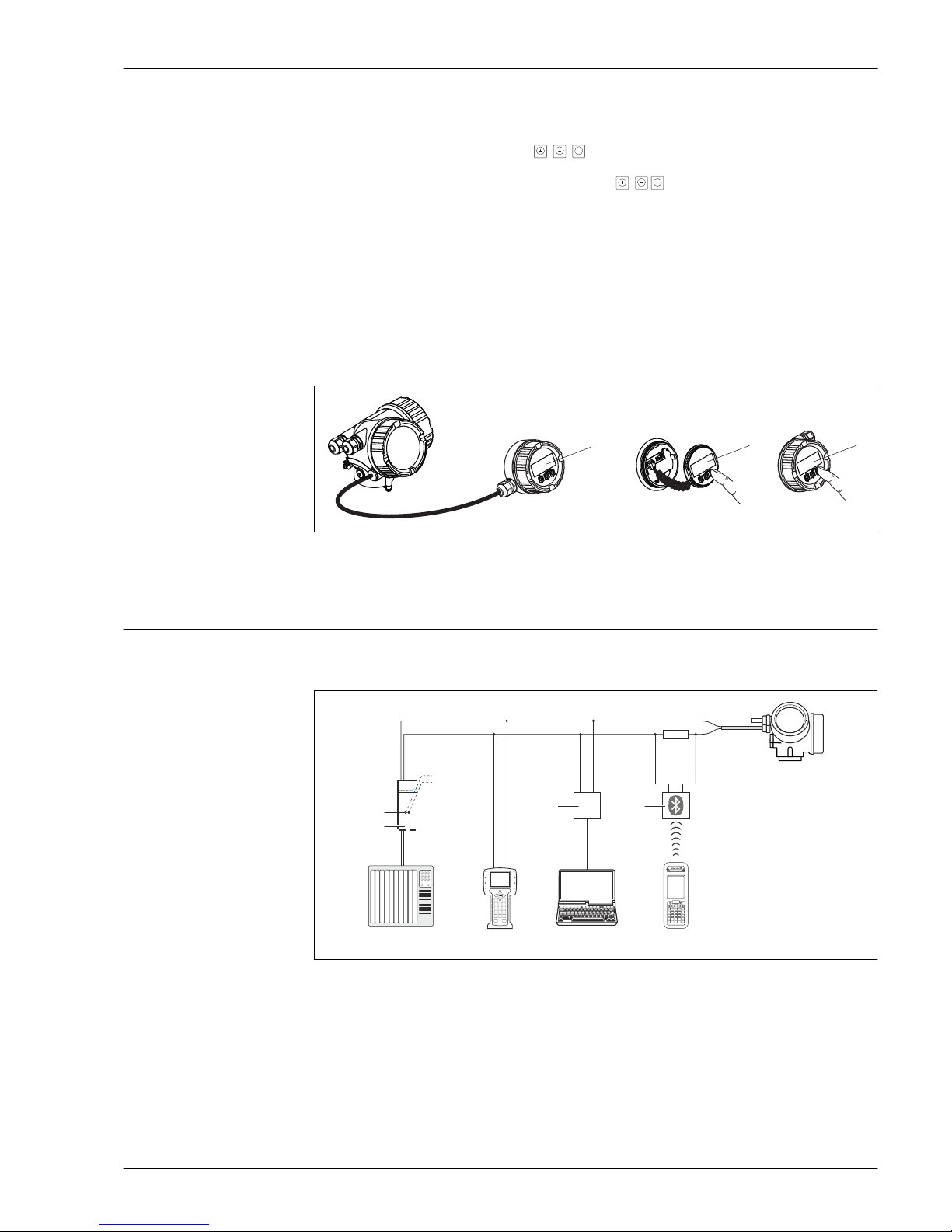
Proline Promag H 200
Endress+Hauser 61
Operating elements
• With order code for "Display; operation", option C:
Local operation with 3 push buttons: , ,
E
• With order code for "Display; operation", option E:
External operation via touch control; 3 optical keys: , ,
E
• Operating elements also accessible in various hazardous areas
Additional functionality
• Data backup function
The device configuration can be saved in the display module.
• Data comparison function
The device configuration saved in the display module can be compared to the current device
configuration.
• Data transfer function
The transmitter configuration can be transmitted to another device using the display module.
Via remote display and operating module FHX50
3
2
1
A0013137
24 Operating options via FHX50
1 Housing of remote display and operating module FHX50
2 SD02 display and operating module, push buttons: cover must be opened for operation
3 SD03 display and operating module, optical buttons: operation possible through cover glass
Remote operation Via HART protocol
This communication interface is available in device versions with a HART output.
1
2
4 5 7
9
6 8
3
A0013764
25 Options for remote operation via HART protocol
1 Control system (e.g. PLC)
2 Transmitter power supply unit, e.g. RN221N (with communication resistor)
3 Connection for Commubox FXA195 and Field Communicator 475
4 Field Communicator 475
5 Computer with operating tool (e.g. FieldCare, AMS Device Manager, SIMATIC PDM)
6 Commubox FXA195 (USB)
7 Field Xpert SFX350 or SFX370
8 VIATOR Bluetooth modem with connecting cable
9 Transmitter
Page 62
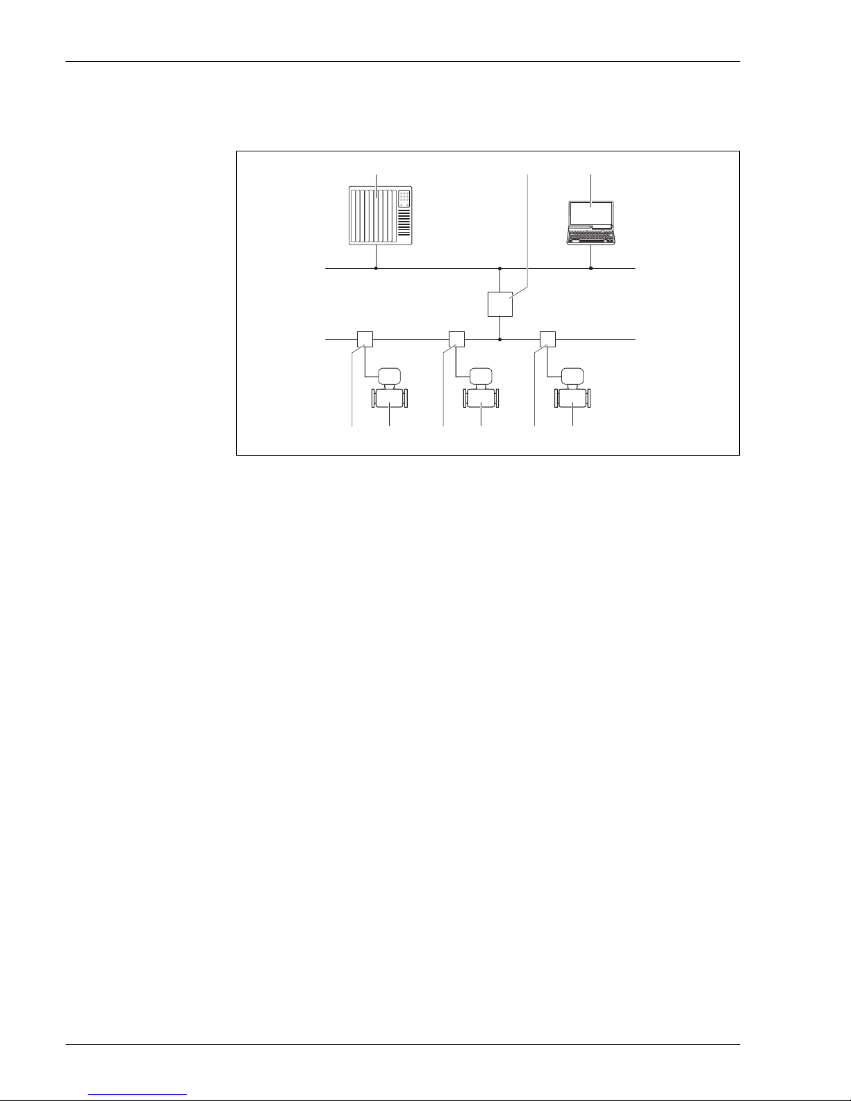
Proline Promag H 200
62 Endress+Hauser
Via PROFIBUS PA network
This communication interface is available in device versions with PROFIBUS PA.
1 32
4
5
666 777
A0019013
26 Options for remote operation via PROFIBUS PA network
1 Automation system
2 Segment coupler PROFIBUS DP/PA
3 Computer with PROFIBUS network card
4 PROFIBUS DP network
5 PROFIBUS PA network
6 Measuring device
7 T-box
Via FOUNDATION Fieldbus network
This communication interface is available in device versions with FOUNDATION Fieldbus.
Page 63
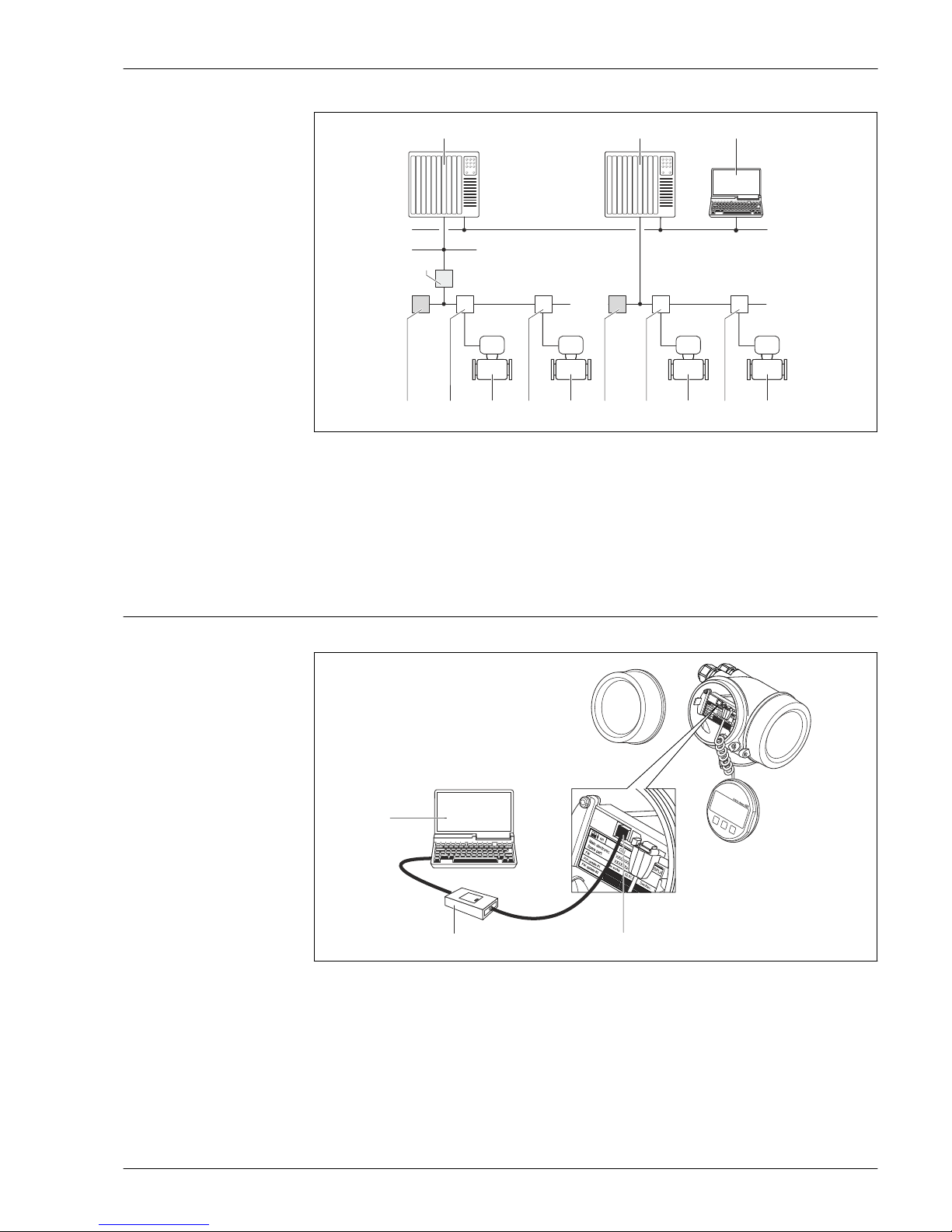
Proline Promag H 200
Endress+Hauser 63
1 2
3
1
99 88 99 88
4
6 6
7 7
5
A0023460
27 Options for remote operation via FOUNDATION Fieldbus network
1 Automation system
2 Computer with FOUNDATION Fieldbus network card
3 Industry network
4 High Speed Ethernet FF-HSE network
5 Segment coupler FF-HSE/FF-H1
6 FOUNDATION Fieldbus FF-H1 network
7 Power supply FF-H1 network
8 T-box
9 Measuring device
Service interface Via service interface (CDI)
+
E
–
12
3
A0014019
1 Service interface (CDI = Endress+Hauser Common Data Interface) of the measuring device
2 Commubox FXA291
3 Computer with "FieldCare" operating tool with COM DTM "CDI Communication FXA291"
Page 64
Proline Promag H 200
64 Endress+Hauser
Certificates and approvals
CE mark
The measuring system is in conformity with the statutory requirements of the applicable EC
Directives. These are listed in the corresponding EC Declaration of Conformity along with the
standards applied.
Endress+Hauser confirms successful testing of the device by affixing to it the CE mark.
C-Tick symbol
The measuring system meets the EMC requirements of the "Australian Communications and Media
Authority (ACMA)".
Ex approval
The measuring device is certified for use in hazardous areas and the relevant safety instructions are
provided in the separate "Safety Instructions" (XA) document. Reference is made to this document on
the nameplate.
The separate Ex documentation (XA) containing all the relevant explosion protection data is
available from your Endress+Hauser sales center.
ATEX, IECEx
Currently, the following versions for use in hazardous areas are available:
Ex d
Category Type of protection
II2G / Zone 1 Ex d[ia] IIC T6-T1 Gb
II2D / Zone 21 Ex tb IIIC T** Db
Ex ia
Category Type of protection
II2G / Zone 1 Ex ia IIC T6-T1 Gb
III2D / Zone 21 Ex tb IIIC T** Db
Ex nA
Category Type of protection
II3G / Zone 2 Ex nA IIC T6-T1 Gc
Ex ic
Category Type of protection
II3G / Zone 2 Ex ic IIC T6-T1 Gc
cCSAus
Currently, the following versions for use in hazardous areas are available:
XP
Category Type of protection
Class I/II/III Division 1 Groups ABCDEFG XP (Ex d Flameproof version)
IS
Category Type of protection
Class I/II/III Division 1 Groups ABCDEFG IS (Ex i Intrinsically safe version), Entity parameter
1)
1) Entity and NIFW parameter in accordance with Control Drawings
Page 65
Proline Promag H 200
Endress+Hauser 65
NI
Category Type of protection
Class I Division 2 Groups ABCD NI (Non-incendive version), NIFW parameter
1)
1) Entity and NIFW parameter in accordance with Control Drawings
Sanitary compatibility
• 3A approval and EHEDG-certified
• Seals → in conformity with FDA (apart from Kalrez seals)
Functional safety
The measuring device can be used for flow monitoring systems (min., max., range) up to SIL 2
(single-channel architecture) and SIL 3 (multichannel architecture with homogeneous redundancy)
and is independently evaluated and certified by the TÜV in accordance with IEC 61508.
The following types of monitoring in safety equipment are possible:
Volume flow
Functional Safety Manual with information on the SIL device → 70
HART certification HART interface
The measuring device is certified and registered by the HCF (HART Communication Foundation).
The measuring system meets all the requirements of the following specifications:
• Certified according to HART 7
• The device can also be operated with certified devices of other manufacturers (interoperability)
FOUNDATION Fieldbus
certification
FOUNDATION Fieldbus interface
The measuring device is certified and registered by the Fieldbus FOUNDATION. The measuring
system meets all the requirements of the following specifications:
• Certified in accordance with FOUNDATION Fieldbus H1
• Interoperability Test Kit (ITK), revision version 6.1.1 (certificate available on request)
• Physical Layer Conformance Test
• The device can also be operated with certified devices of other manufacturers (interoperability)
Certification PROFIBUS PROFIBUS interface
The measuring device is certified and registered by the PROFIBUS User Organization (PNO). The
measuring system meets all the requirements of the following specifications:
• Certified in accordance with PROFIBUS PA Profile 3.02
• The device can also be operated with certified devices of other manufacturers (interoperability)
Other standards and
guidelines
• EN 60529
Degrees of protection provided by enclosures (IP code)
• EN 61010-1
Safety requirements for electrical equipment for measurement, control and laboratory use
• IEC/EN 61326
Emission in accordance with Class A requirements. Electromagnetic compatibility (EMC
requirements).
• ANSI/ISA-61010-1 (82.02.01): 2004
Safety Requirements for Electrical Equipment for Measurement, Control and Laboratory Use - Part
1 General Requirements
• CAN/CSA-C22.2 No. 61010-1-04
Safety Requirements for Electrical Equipment for Measurement, Control and Laboratory Use - Part
1 General Requirements
• NAMUR NE 21
Electromagnetic compatibility (EMC) of industrial process and laboratory control equipment
• NAMUR NE 32
Data retention in the event of a power failure in field and control instruments with
microprocessors
• NAMUR NE 43
Standardization of the signal level for the breakdown information of digital transmitters with
analog output signal.
• NAMUR NE 53
Software of field devices and signal-processing devices with digital electronics
Page 66
Proline Promag H 200
66 Endress+Hauser
• NAMUR NE 105
Specifications for integrating fieldbus devices in engineering tools for field devices
• NAMUR NE 107
Self-monitoring and diagnosis of field devices
• NAMUR NE 131
Requirements for field devices for standard applications
Ordering information
Detailed ordering information is available from the following sources:
• In the Product Configurator on the Endress+Hauser website: www.endress.com → Select your
country → Products → Select measuring technology, software or components → Select the product
(picklists: measurement method, product family etc.) → Device support (right-hand column):
Configure the selected product → The Product Configurator for the selected product opens.
• From your Endress+Hauser Sales Center: www.addresses.endress.com
Product Configurator - the tool for individual product configuration
• Up-to-the-minute configuration data
• Depending on the device: Direct input of measuring point-specific information such as
measuring range or operating language
• Automatic verification of exclusion criteria
• Automatic creation of the order code and its breakdown in PDF or Excel output format
• Ability to order directly in the Endress+Hauser Online Shop
Application packages
Many different application packages are available to enhance the functionality of the device. Such
packages might be needed to address safety aspects or specific application requirements.
The application packages can be ordered with the device or subsequently from Endress+Hauser.
Detailed information on the order code in question is available from your local Endress+Hauser sales
center or on the product page of the Endress+Hauser website: www.endress.com.
Diagnostics functions
Package Description
HistoROM extended
function
Comprises extended functions concerning the event log and the activation of the
measured value memory.
Event log:
Memory volume is extended from 20 message entries (basic version) to up to 100
entries.
Data logging (line recorder):
• Memory capacity for up to 1000 measured values is activated.
• 250 measured values can be output via each of the 4 memory channels. The
recording interval can be defined and configured by the user.
• Data logging is visualized via the local display or FieldCare.
Heartbeat Technology
Package Description
Heartbeat Verification Heartbeat Verification:
Makes it possible to check the device functionality on demand when the device is
installed, without having to interrupt the process.
• Access via local operation or other operating interfaces, such as FieldCare for
instance.
• Documentation of device functionality within the framework of manufacturer
specifications, for proof testing for instance.
• End-to-end, traceable documentation of the verification results, including report.
• Makes it possible to extend calibration intervals in accordance with operator's
risk assessment.
Page 67
Proline Promag H 200
Endress+Hauser 67
Accessories
Various accessories, which can be ordered with the device or subsequently from Endress+Hauser, are
available for the device. Detailed information on the order code in question is available from your
local Endress+Hauser sales center or on the product page of the Endress+Hauser website:
www.endress.com.
Device-specific accessories For the transmitter
Accessories Description
Remote display
FHX50
FHX50 housing to accommodate a display module → 61.
• FHX50 housing suitable for:
– SD02 display module (push buttons)
– SD03 display module (touch control)
• Housing material:
– Plastic PBT
– Stainless steel CF-3M (316L, 1.4404)
• Length of connecting cable: up to max. 60 m (196 ft)
(cable lengths available for order: 5 m (16 ft), 10 m (32 ft), 20 m (65 ft),
30 m (98 ft))
The measuring device can be ordered with the FHX50 housing and a display
module. The following options must be selected in the separate order codes:
• Order code for measuring device, feature 030:
Option L or M "Prepared for FHX50 display"
• Order code for FHX50 housing, feature 050 (device version):
Option A "Prepared for FHX50 display"
• Order code for FHX50 housing, depends on the desired display module in feature
020 (display, operation):
– Option C: for an SD02 display module (push buttons)
– Option E: for an SD03 display module (touch control)
The FHX50 housing can also be ordered as a retrofit kit. The measuring device
display module is used in the FHX50 housing. The following options must be
selected in the order code for the FHX50 housing:
• Feature 050 (measuring device version): option B "Not prepared for FHX50
display"
• Feature 020 (display, operation): option A "None, existing displayed used"
For details, see Special Documentation SD01007F
Overvoltage protection for
2-wire devices
Ideally, the overvoltage protection module should be ordered directly with the
device. See product structure, characteristic 610 "Accessory mounted", option NA
"Overvoltage protection". Separate order necessary only if retrofitting.
• OVP10: For 1-channel devices (characteristic 020, option A):
• OVP20: For 2-channel devices (characteristic 020, options B, C, E or G)
For details, see Special Documentation SD01090F.
Weather protection cover Is used to protect the measuring device from the effects of the weather: e.g.
rainwater, excess heating from direct sunlight or extreme cold in winter.
For details, see Special Documentation SD00333F
For the sensor
Accessories Description
Seal set For the regular replacement of seals for the sensor.
Welding jig Welded connection as process connection: welding jig for installation in pipe.
Page 68
Proline Promag H 200
68 Endress+Hauser
Grounding rings Are used to ground the fluid in lined measuring tubes to ensure proper
measurement.
For details, see Installation Instructions EA00070D
Mounting kit Consists of:
• 2 process connections
• Screws
• Seals
Communication-specific
accessories
Accessories Description
Commubox FXA195
HART
For intrinsically safe HART communication with FieldCare via the USB interface.
For details, see "Technical Information" TI00404F
Commubox FXA291 Connects Endress+Hauser field devices with a CDI interface (= Endress+Hauser
Common Data Interface) and the USB port of a computer or laptop.
For details, see the "Technical Information" document TI405C/07
HART Loop Converter
HMX50
Is used to evaluate and convert dynamic HART process variables to analog current
signals or limit values.
For details, see "Technical Information" TI00429F and Operating Instructions
BA00371F
Wireless HART adapter
SWA70
Is used for the wireless connection of field devices.
The WirelessHART adapter can be easily integrated into field devices and existing
infrastructures, offers data protection and transmission safety and can be operated
in parallel with other wireless networks with minimum cabling complexity.
For details, see Operating Instructions BA00061S
Fieldgate FXA320 Gateway for the remote monitoring of connected 4-20 mA measuring devices via a
Web browser.
For details, see "Technical Information" TI00025S and Operating Instructions
BA00053S
Fieldgate FXA520 Gateway for the remote diagnostics and remote configuration of connected HART
measuring devices via a Web browser.
For details, see "Technical Information" TI00025S and Operating Instructions
BA00051S
Field Xpert SFX350 Field Xpert SFX350 is a mobile computer for commissioning and maintenance. It
enables efficient device configuration and diagnostics for HART and FOUNDATION
Fieldbus devices in the non-Ex area.
For details, see Operating Instructions BA01202S
Field Xpert SFX370 Field Xpert SFX370 is a mobile computer for commissioning and maintenance. It
enables efficient device configuration and diagnostics for HART and FOUNDATION
Fieldbus devices in the non-Ex area and the Ex area.
For details, see Operating Instructions BA01202S
Service-specific accessories
Accessories Description
Applicator Software for selecting and sizing Endress+Hauser measuring devices:
• Calculation of all the data needed to determine the optimum flowmeter: e.g.
nominal diameter, pressure drop, performance characteristics or process
connections.
• Graphic illustration of the calculation results
Administration, documentation and access to all project-related data and
parameters throughout the entire life cycle of a project.
Applicator is available:
• Via the Internet: https://wapps.endress.com/applicator
• On CD-ROM for local PC installation.
Page 69
Proline Promag H 200
Endress+Hauser 69
W@M Life cycle management for your plant
W@M supports you with a wide range of software applications over the entire
process: from planning and procurement, to the installation, commissioning and
operation of the measuring devices. All the relevant information is available for
every measuring device over time entire life cycle, such as the device status, spare
parts, device-specific documentation, etc.
The application already contains the data of your Endress+Hauser device. Endress
+Hauser also takes care of maintaining and updating the data records.
W@M is available:
• Via the Internet: www.endress.com/lifecyclemanagement
• On CD-ROM for local PC installation.
FieldCare FDT-based plant asset management tool from Endress+Hauser.
It can configure all smart field units in your system and helps you manage them. By
using the status information, it is also a simple but effective way of checking their
status and condition.
For details, see Operating Instructions BA00027S and BA00059S
System components
Accessories Description
Memograph M graphic
display recorder
The Memograph M graphic display recorder provides information on all relevant
measured variables. Measured values are recorded correctly, limit values are
monitored and measuring points analyzed. The data are stored in the 256 MB
internal memory and also on a SD card or USB stick.
For details, see "Technical Information" TI00133R and Operating Instructions
BA00247R
RN221N Active barrier with power supply for safe separation of 4-20 mA standard signal
circuits. Offers bidirectional HART transmission.
For details, see "Technical Information" TI00073R and Operating Instructions
BA00202R
RNS221 Supply unit for powering two 2-wire measuring devices solely in the non-Ex area.
Bidirectional communication is possible via the HART communication jacks.
For details, see "Technical Information" TI00081R and Brief Operating
Instructions KA00110R
Documentation
For an overview of the scope of the associated Technical Documentation, refer to the following:
• The W@M Device Viewer : Enter the serial number from the nameplate
(www.endress.com/deviceviewer)
• The Endress+Hauser Operations App: Enter the serial number from the nameplate or scan the
2-D matrix code (QR code) on the nameplate.
Standard documentation Brief Operating Instructions
Measuring device Documentation code
Promag H 200 KA01120D
Operating Instructions
Measuring device Documentation code
HART FOUNDATION Fieldbus PROFIBUS PA
Promag H 200 BA01110D BA01377D BA01375D
Page 70
Proline Promag H 200
70 Endress+Hauser
Device Parameters
Measuring device Documentation code
HART FOUNDATION Fieldbus PROFIBUS PA
Promag 200 GP01026D GP01028D GP01027D
Supplementary devicedependent documentation
Safety Instructions
Contents Documentation code
ATEX/IECEx Ex d[ia], Ex tb XA01015D
ATEX/IECEx Ex ia, Ex tb XA01016D
ATEX/IECEx Ex nA, Ex ic XA01017D
cCSAus XP (Ex d) XA01018D
cCSAus IS (Ex i) XA01019D
NEPSI Ex d XA01179D
NEPSI Ex i XA01178D
NEPSI Ex nA, Ex ic XA01180D
INMETRO Ex d XA01309D
INMETRO Ex i XA01310D
INMETRO Ex nA XA01311D
Special Documentation
Contents Documentation code
Functional Safety Manual SD01451D
Heartbeat Technology SD01452D
Installation Instructions
Contents Documentation code
Installation Instructions for spare part sets Specified for each individual accessory
Registered trademarks
HART
®
Registered trademark of the HART Communication Foundation, Austin, USA
PROFIBUS
®
Registered trademark of the PROFIBUS User Organization, Karlsruhe, Germany
FOUNDATIONTM Fieldbus
Registration-pending trademark of the Fieldbus Foundation, Austin, Texas, USA
Applicator®, FieldCare®, Field XpertTM, HistoROM®, Heartbeat Technology
TM
Registered or registration-pending trademarks of the Endress+Hauser Group
Page 71

Page 72

www.addresses.endress.com
 Loading...