

Endress+Hauser Proline Promag 10W, Proline Promag 10L, Proline Promag 10P, Proline Promag 10H, Proline Promag 10D Operating Manual
Page 1
BA00082D/06/EN/19.17
71385945
Valid as of software version
V 1.04.00 (device software)
Products Solutions Services
Operating Instructions
Proline Promag 10
HART
Electromagnetic flowmeter
6
Page 2

Products Solutions Services
Page 3

Promag 10
Table of contents
1 Safety instructions . . . . . . . . . . . . . . . . . . 4
1.1 Designated use . . . . . . . . . . . . . . . . . . . . . . . . . . . . . 4
1.2 Installation, commissioning and operation . . . . . . 4
1.3 Operational safety . . . . . . . . . . . . . . . . . . . . . . . . . . . 4
1.4 Return . . . . . . . . . . . . . . . . . . . . . . . . . . . . . . . . . . . . . 5
1.5 Notes on safety conventions and icons . . . . . . . . . 5
2 Identification . . . . . . . . . . . . . . . . . . . . . . 6
2.1 Device designation . . . . . . . . . . . . . . . . . . . . . . . . . . 6
2.2 Certificates and approvals . . . . . . . . . . . . . . . . . . . . 8
2.3 Registered trademarks . . . . . . . . . . . . . . . . . . . . . . . 8
3 Installation . . . . . . . . . . . . . . . . . . . . . . . . 9
3.1 Incoming acceptance, transport and storage . . . . . 9
3.2 Mounting requirements . . . . . . . . . . . . . . . . . . . . 11
3.3 Installing the measuring device . . . . . . . . . . . . . 18
3.4 Post-installation check . . . . . . . . . . . . . . . . . . . . . 45
4 Wiring . . . . . . . . . . . . . . . . . . . . . . . . . . . 46
4.1 Connecting the remote version . . . . . . . . . . . . . . 46
4.2 Connecting the measuring unit . . . . . . . . . . . . . . 52
4.3 Potential equalization . . . . . . . . . . . . . . . . . . . . . . 54
4.4 Degree of protection . . . . . . . . . . . . . . . . . . . . . . . 57
4.5 Post-connection check . . . . . . . . . . . . . . . . . . . . . 58
5 Operation. . . . . . . . . . . . . . . . . . . . . . . . . 59
9 Troubleshooting . . . . . . . . . . . . . . . . . . 77
9.1 Troubleshooting instructions . . . . . . . . . . . . . . . . 77
9.2 System error messages . . . . . . . . . . . . . . . . . . . . . 78
9.3 Process error messages . . . . . . . . . . . . . . . . . . . . . 79
9.4 Process errors without messages . . . . . . . . . . . . . 80
9.5 Response of outputs to errors . . . . . . . . . . . . . . . . 81
9.6 Spare parts . . . . . . . . . . . . . . . . . . . . . . . . . . . . . . . . 82
9.7 Return . . . . . . . . . . . . . . . . . . . . . . . . . . . . . . . . . . . 86
9.8 Disposal . . . . . . . . . . . . . . . . . . . . . . . . . . . . . . . . . . 86
9.9 Software history . . . . . . . . . . . . . . . . . . . . . . . . . . . 86
10 Technical data . . . . . . . . . . . . . . . . . . . . 87
10.1 Application . . . . . . . . . . . . . . . . . . . . . . . . . . . . . . . 87
10.2 Function and system design . . . . . . . . . . . . . . . . . 87
10.3 Input . . . . . . . . . . . . . . . . . . . . . . . . . . . . . . . . . . . . . 87
10.4 Output . . . . . . . . . . . . . . . . . . . . . . . . . . . . . . . . . . . 90
10.5 Power supply . . . . . . . . . . . . . . . . . . . . . . . . . . . . . . 91
10.6 Performance characteristics . . . . . . . . . . . . . . . . . 92
10.7 Installation . . . . . . . . . . . . . . . . . . . . . . . . . . . . . . . 92
10.8 Environment . . . . . . . . . . . . . . . . . . . . . . . . . . . . . . 92
10.9 Process . . . . . . . . . . . . . . . . . . . . . . . . . . . . . . . . . . . 93
10.10 Mechanical construction . . . . . . . . . . . . . . . . . . 100
10.11 Operability . . . . . . . . . . . . . . . . . . . . . . . . . . . . . . 113
10.12 Certificates and approvals . . . . . . . . . . . . . . . . . 114
10.13 Ordering information . . . . . . . . . . . . . . . . . . . . . 115
10.14 Accessories . . . . . . . . . . . . . . . . . . . . . . . . . . . . . 115
10.15 Documentation . . . . . . . . . . . . . . . . . . . . . . . . . . 115
5.1 Display and operating elements . . . . . . . . . . . . . 59
5.2 Brief operating instructions on the function matrix
60
5.3 Displaying error messages . . . . . . . . . . . . . . . . . . 62
5.4 Communication . . . . . . . . . . . . . . . . . . . . . . . . . . . 63
6 Commissioning. . . . . . . . . . . . . . . . . . . . 70
6.1 Function check . . . . . . . . . . . . . . . . . . . . . . . . . . . 70
6.2 Switching on the measuring device . . . . . . . . . . 70
6.3 Brief commissioning guide . . . . . . . . . . . . . . . . . 70
6.4 Commissioning after installing a new electronics
board . . . . . . . . . . . . . . . . . . . . . . . . . . . . . . . . . . . . 71
6.5 Empty-pipe/full-pipe adjustment . . . . . . . . . . . . 72
7 Maintenance. . . . . . . . . . . . . . . . . . . . . . 73
7.1 Exterior cleaning . . . . . . . . . . . . . . . . . . . . . . . . . . 73
7.2 Seals . . . . . . . . . . . . . . . . . . . . . . . . . . . . . . . . . . . . 73
8 Accessories . . . . . . . . . . . . . . . . . . . . . . . 74
8.1 Device-specific accessories . . . . . . . . . . . . . . . . . . 74
8.2 Communication-specific accessories . . . . . . . . . 75
8.3 Service-specific accessories . . . . . . . . . . . . . . . . . 75
11 Appendix . . . . . . . . . . . . . . . . . . . . . . . 116
11.1 Illustration of the function matrix . . . . . . . . . . 116
11.2 Group SYSTEM UNITS . . . . . . . . . . . . . . . . . . . . 117
11.3 Group OPERATION . . . . . . . . . . . . . . . . . . . . . . . 119
11.4 USER INTERFACE . . . . . . . . . . . . . . . . . . . . . . . . 120
11.5 Group TOTALIZER . . . . . . . . . . . . . . . . . . . . . . . 121
11.6 Group CURRENT OUTPUT . . . . . . . . . . . . . . . . . 122
11.7 Group PULSE/STATUS OUTPUT . . . . . . . . . . . . 124
11.8 Group COMMUNICATION . . . . . . . . . . . . . . . . . 129
11.9 Group PROCESS PARAMETER . . . . . . . . . . . . . 130
11.10 Group SYSTEM PARAMETER . . . . . . . . . . . . . . 132
11.11 Group SENSOR DATA . . . . . . . . . . . . . . . . . . . . . 135
11.12 Group SUPERVISION . . . . . . . . . . . . . . . . . . . . . 137
11.13 Group SIMULATION SYSTEM . . . . . . . . . . . . . . 139
11.14 Group SENSOR VERSION . . . . . . . . . . . . . . . . . . 139
11.15 Group AMPLIFIER VERSION . . . . . . . . . . . . . . . 139
11.16 Factory settings . . . . . . . . . . . . . . . . . . . . . . . . . . 140
Index . . . . . . . . . . . . . . . . . . . . . . . . . . . 144
Endress+Hauser 3
Page 4

Safety instructions Promag 10
1 Safety instructions
1.1 Designated use
The measuring device described in this Operating Manual is to be used only for measuring
the flow rate of conductive fluids in closed pipes.
Most liquids can be measured as of a minimum conductivity of 50 S/cm.
Examples:
• Acids, alkalis
• Drinking water, wastewater, sewage sludge
• Milk, beer, wine, mineral water, etc.
Resulting from incorrect use or from use other than that designated the operational safety
of the measuring devices can be suspended. The manufacturer accepts no liability for
damages being produced from this.
1.2 Installation, commissioning and operation
Please note the following:
• Installation, connection to the electricity supply, commissioning and maintenance of the
device must be carried out by trained, qualified specialists authorized to perform such work
by the facility's owner-operator. The specialist must have read and understood this
Operating Manual and must follow the instructions it contains.
• The device must be operated by persons authorized and trained by the facility's owneroperator. Strict compliance with the instructions in the Operating Manual is mandatory.
• With regard to special fluids, including fluids used for cleaning, Endress+Hauser will be
happy to assist in clarifying the corrosion-resistant properties of wetted materials.
However, minor changes in temperature, concentration or in the degree of contamination
in the process may result in variations in corrosion resistance. For this reason,
Endress+Hauser does not accept any responsibility with regard to the corrosion resistance
of wetted materials in a specific application.
The user is responsible for the choice of suitable wetted materials in the process.
• If welding work is performed on the piping system, do not ground the welding appliance
through the Promag flowmeter.
• The installer must ensure that the measuring system is correctly wired in accordance with
the wiring diagrams. The transmitter must be grounded apart from when special
protective measures are taken (e.g. galvanically isolated SELV or PELV power supply)
• Invariably, local regulations governing the opening and repair of electrical devices apply.
1.3 Operational safety
Please note the following:
• Measuring systems for use in hazardous environments are accompanied by separate Ex
documentation, which is an integral part of this Operating Manual. Strict compliance with
the installation instructions and ratings as stated in this supplementary documentation is
mandatory. The symbol on the front of this Ex documentation indicates the approval and
the certification body (e.g.
• The measuring device complies with the general safety requirements in accordance with
EN 61010-1, the EMC requirements of IEC/EN 61326 and NAMUR Recommendations
NE 21 and NE 43.
• Depending on the application, the seals of the process connections of the Promag H sensor
require periodic replacement.
• When hot fluid passes through the measuring tube, the surface temperature of the
housing increases. In the case of the sensor, in particular, users should expect
temperatures that can be close to the fluid temperature. If the temperature of the fluid is
high, implement sufficient measures to prevent burning or scalding.
4 Endress+Hauser
0 Europe, 2 USA, 1 Canada).
Page 5

Promag 10 Safety instructions
• The manufacturer reserves the right to modify technical data without prior notice. Your
Endress+Hauser distributor will supply you with current information and updates to these
Operating Instructions.
1.4 Return
The measuring device must be returned if repairs or a factory calibration are required, or if
the wrong measuring device has been ordered or delivered. According to legal regulations,
Endress+Hauser, as an ISO-certified company, is required to follow certain procedures when
handling returned products that are in contact with medium.
To ensure swift, safe and professional device returns, please read the return procedures and
conditions on the Endress+Hauser website at www.services.endress.com/return-material
1.5 Notes on safety conventions and icons
The devices are designed to meet state-of-the-art safety requirements, have been tested,
and left the factory in a condition in which they are safe to operate. The devices comply with
the applicable standards and regulations in accordance with EN 61010-1 "Safety
requirements for electrical equipment for measurement, control and laboratory use".
The devices can, however, be a source of danger if used incorrectly or for anything other than
the designated use. Consequently, always pay particular attention to the safety instructions
indicated in this Operating Manual by the following icons:
#
Warning!
"Warning" indicates an action or procedure which, if not performed correctly, can result in
injury or a safety hazard. Comply strictly with the instructions and proceed with care.
Caution!
"
"Caution" indicates an action or procedure which, if not performed correctly, can result in
incorrect operation or destruction of the device. Comply strictly with the instructions.
!
Note!
"Note" indicates an action or procedure which, if not performed correctly, can have an indirect
effect on operation or trigger an unexpected response on the part of the device.
Endress+Hauser 5
Page 6
Identification Promag 10
Promag 10
-20°C (-4°F) <Tamb<+60°C (+140°F)
IP67 / NEMA/Type 4XOrder Code:
Ser.No.:
TAG No.:
10PXX-XXXXXXXXXXXX
12345678901
ABCDEFGHJKLMNPQRST
20-28VAC/11-40VDC
50-60Hz
I-OUT (HART), PULSE-OUT
8VA/6W
i
EPD / MSÜ
2
3
4
5
9
8
1
N12895
6
7
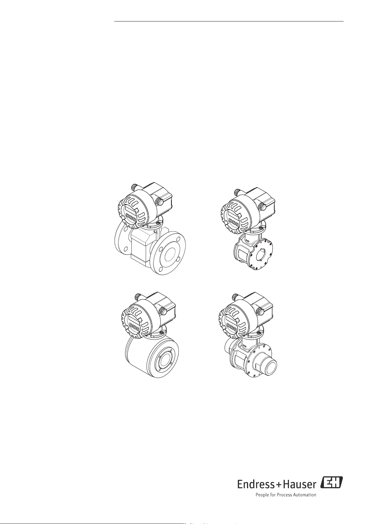
2 Identification
2.1 Device designation
The flow measuring system consists of the following components:
• Promag 10 transmitter
• Promag D/E/H/L/P/W sensor
In the compact version, the transmitter and sensor form a single mechanical unit; in the
remote version they are installed separately.
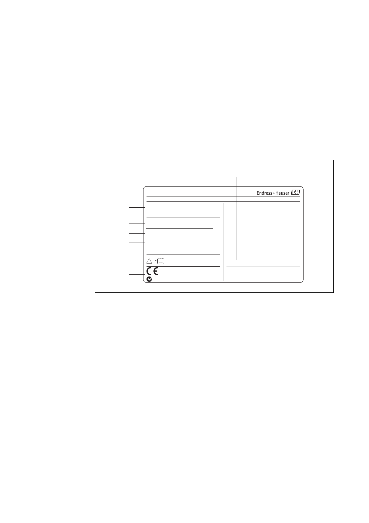
2.1.1 Nameplate of the transmitter
Fig. 1: Nameplate specifications for the "Promag 10" transmitter (example)
1 Ordering code/serial number: See the specifications on the order confirmation for the meanings of the individual letters and
digits.
2 Power supply, frequency, power consumption
3 Additional information:
EPD/MSÜ: with Empty Pipe Detection
4 Outputs available:
I-OUT (HART): with current output (HART)
PULSE-OUT: with pulse/status output
5 Reserved for information on special products
6 Observe device documentation
7 Reserved for additional information on device version (approvals, certificates)
8 Permitted ambient temperature range
9 Degree of protection
6 Endress+Hauser
A0005395
Page 7
Promag 10 Identification
-20°C (-4°F)<Tamb<+60°C (+140°F) NEMA/Type4X
50PXX-XXXXXXXXXXXX
1.0000/0000
–10 ...150°C/+14 ...300°F°C °F
PFA
12345678901 RY
ABCDEFGHJKLMNPQRST
DN100 DIN EN PN40/ pnom =PS= 40bar
EPD/MSÜ, R/B
TM:
Order Code:
Materials:
K-factor:
Ser.No.:
TAG No.:
PROMAG P
1
2
3
7
13
12
1.4435/316L
Electrodes:
0.2% CAL
4
5
6
10
1
1
i
9
8
IP67
2007
N12895
24
+
25
–
26
+
27
–
L1 (L+)
12
N (L–)
$
PULSE-OUT
fmax: 100 Hz
Passive: 30 VDC
250 mA
I-OUT (HART)
Active: 4...20 mA
RLmax. = 700 Ohm
HART
RLmin. = 250 Ohm
Supply /
Versorgung /
Tension
d’Alimentation
See operating manual
Betriebsanleitung beachten
Observer Manual d’Instruction
319740-0000
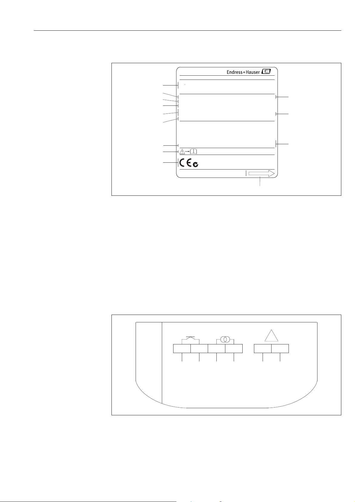
2.1.2 Nameplate of the sensor
A0004374
Fig. 2: Nameplate specifications for the "Promag" sensor (example)
1 Ordering code/serial number: See the specifications on the order confirmation for the meanings of the individual letters and
digits.
2 Calibration factor with zero point
3 Nominal diameter/Pressure rating
4 Fluid temperature range
5 Materials: lining/measuring electrodes
6 Reserved for information on special products
7 Permitted ambient temperature range
8 Observe device documentation
9 Reserved for additional information on device version (approvals, certificates)
10 Calibration tolerance
11 Additional information (examples):
– EPD/MSÜ: with Empty Pipe Detection electrode
– R/B: with reference electrode
12 Degree of protection
13 Flow direction
Endress+Hauser 7
2.1.3 Nameplate, connections
Fig. 3: Nameplate specifications for transmitter (example)
A0005394
Page 8

Identification Promag 10
2.2 Certificates and approvals
The devices are designed to meet state-of-the-art safety requirements in accordance with
sound engineering practice. They have been tested and left the factory in a condition in
which they are safe to operate.
The devices comply with the applicable standards and regulations in accordance with EN
61010-1 "Safety requirements for electrical equipment for measurement, control and
laboratory use" and with the EMC requirements of IEC/EN 61326.
The measuring system described in this Operating Manual is therefore in conformity with
the statutory requirements of the EC Directives. Endress+Hauser confirms successful testing
of the device by affixing to it the CE mark.
The measuring system meets the EMC requirements of the "Australian Communications and
Media Authority (ACMA)".
2.3 Registered trademarks
KALREZ® and VITON
Registered trademarks of E.I. Du Pont de Nemours & Co., Wilmington, USA
TRI-CLAMP®
Registered trademark of Ladish & Co., Inc., Kenosha, USA
®
HART
Registered trademark of the HART Communication Foundation, Austin, USA
®
Applicator®, FieldCare®, Fieldcheck®
Registered or registration-pending trademarks of the Endress+Hauser Group
8 Endress+Hauser
Page 9

Promag 10 Installation
3Installation
3.1 Incoming acceptance, transport and storage
3.1.1 Incoming acceptance
On receipt of the goods, check the following:
• Check the packaging and the contents for damage.
• Check the shipment, make sure nothing is missing and that the scope of supply matches
your order.
3.1.2 Transport
The following instructions apply to unpacking and to transporting the device to its final
location:
• Transport the devices in the containers in which they are delivered.
• Do not remove the protective plates or caps on the process connections until you are ready
to install the device. This is particularly important in the case of sensors with PTFE linings.
"
#
Special notes on flanged devices
Caution!
• The wooden covers mounted on the flanges from the factory protect the linings on the
flanges during storage and transportation. In case of Promag L they are additionally used
to hold the lap joint flanges in place. Do not remove these covers until immediately before
the device in the pipe.
• Do not lift flanged devices by the transmitter housing, or the connection housing in the
case of the remote version.
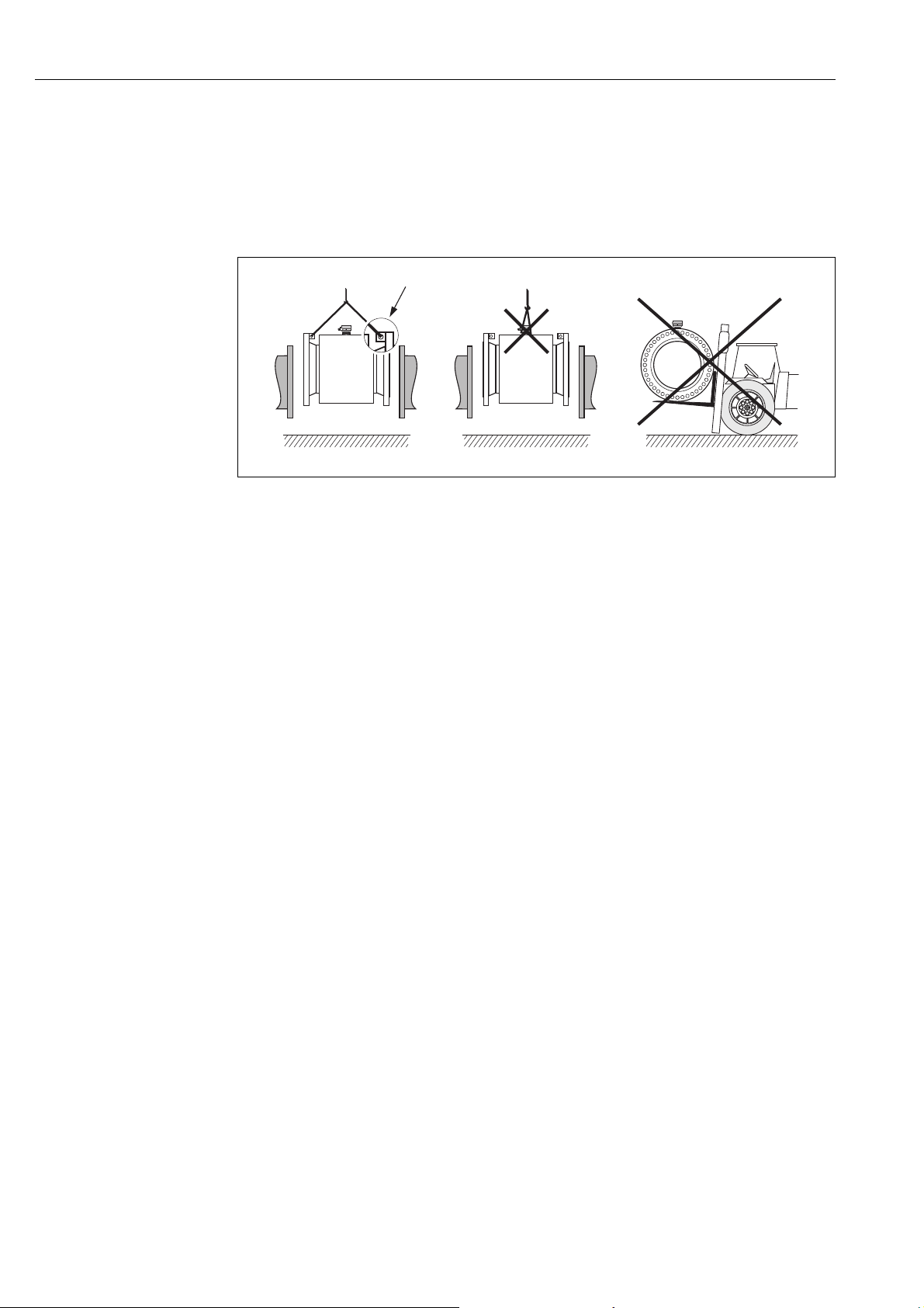
Transporting flanged devices DN ≤ 300 (12")
Use webbing slings slung round the two process connections.
Do not use chains, as they could damage the housing.
Warning!
Risk of injury if the measuring device slips. The center of gravity of the assembled measuring
device might be higher than the points around which the slings are slung.
At all times, therefore, make sure that the device does not unexpectedly turn around its axis
or slip.
A0005575
Fig. 4: Transporting sensors with DN ≤ 300 (12")
Endress+Hauser 9
Page 10
Installation Promag 10
Transporting flanged devices DN ≥ 350 (14")
Use only the metal eyes on the flanges for transporting the device, lifting it and positioning
the sensor in the piping.
Caution!
"
Do not attempt to lift the sensor with the tines of a fork-lift truck beneath the metal casing.
This would buckle the casing and damage the internal magnetic coils.
A0004295
Fig. 5: Transporting sensors with DN ≥ 350 (14")
3.1.3 Storage
Please note the following:
• Pack the measuring device in such a way as to protect it reliably against impact for storage
(and transportation). The original packaging provides optimum protection.
• The storage temperature corresponds to the operating temperature range of the
measuring transmitter and the appropriate measuring sensors 92.
• Do not remove the protective plates or caps on the process connections until you are ready
to install the device. This is particularly important in the case of sensors with PTFE linings.
• The measuring device must be protected against direct sunlight during storage in order to
avoid unacceptably high surface temperatures.
• Choose a storage location where moisture does not collect in the measuring device. This
will help prevent fungus and bacteria infestation which can damage the liner.
10 Endress+Hauser
Page 11
Promag 10 Installation
h 2 x DN³
1 1
3.2 Mounting requirements
3.2.1 Dimensions
The dimensions and installation lengths of the sensor and transmitter can be found in the
"Technical Information" for the device in question. This document can be downloaded as a
PDF file from www.endress.com. A list of the "Technical Information" documents available is
provided in the "Documentation" section on 115.
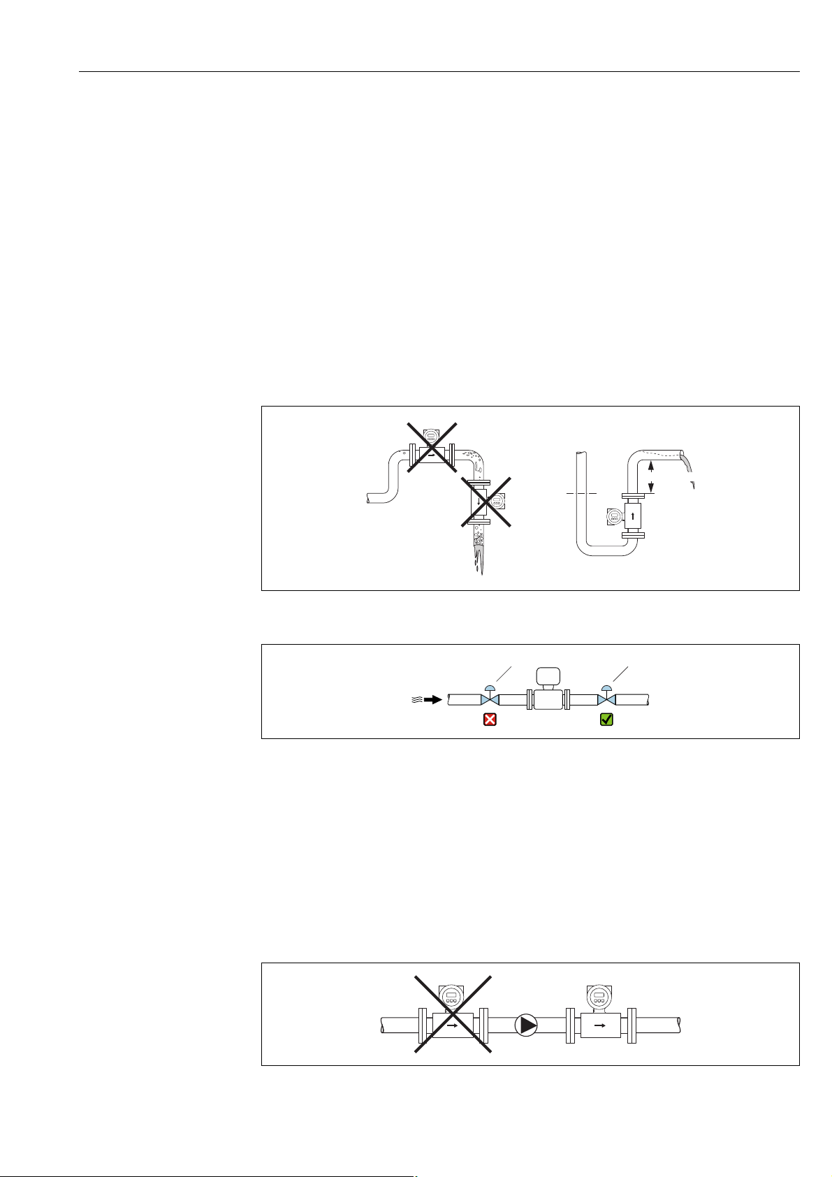
3.2.2 Mounting location
Entrained air or gas bubble formation in the measuring tube can result in an increase in
measuring errors.
Avoid the following locations:
• Highest point of a pipeline. Risk of air accumulating!
• Directly upstream from a free pipe outlet in a vertical pipeline.
A0008154
Fig. 6: Mounting location
A0033017
Fig. 7: Installation of the sensor after a control valve is not recommended
1 Control valve
Installation of pumps
Do not install the sensor on the intake side of a pump. This precaution is to avoid low
pressure and the consequent risk of damage to the lining of the measuring tube. Information
on the lining's resistance to partial vacuum can be found on 96.
It might be necessary to install pulse dampers in systems incorporating reciprocating,
diaphragm or peristaltic pumps. Information on the measuring system's resistance to
vibration and shock can be found on 93.
A0003203
Fig. 8: Installation of pumps
Endress+Hauser 11
Page 12
Installation Promag 10
5 x DN
2 x DN
³
³
h
2
1
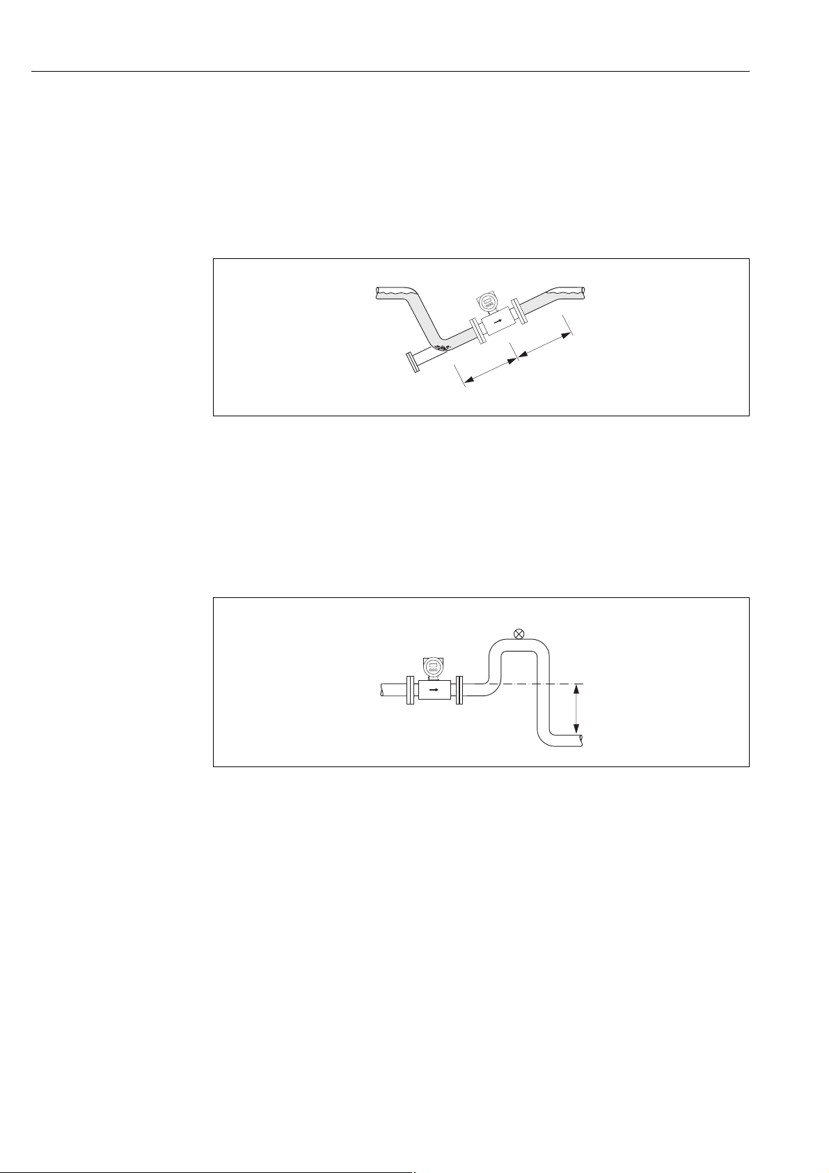
Partially filled pipes
Partially filled pipes with gradients necessitate a drain-type configuration.
The Empty Pipe Detection function (EPD 72) offers additional protection by detecting
empty or partially filled pipes.
Caution!
"
Risk of solids accumulating. Do not install the sensor at the lowest point in the drain. It is
advisable to install a cleaning valve.
A0008155
Fig. 9: Installation in a partially filled pipe
Down pipes
Install a siphon or a vent valve downstream of the sensor in down pipes whose length
h 5 m (16.4 ft). This precaution is to avoid low pressure and the consequent risk of
damage to the lining of the measuring tube.
This measure also prevents the system losing prime, which could cause air pockets.
Information on the lining's resistance to partial vacuum can be found on 96.
Fig. 10: Measures for installation in a down pipe
1Vent valve
2Pipe siphon
hLength of down pipe
A0008157
12 Endress+Hauser
Page 13
Promag 10 Installation
A
1
22
A
3
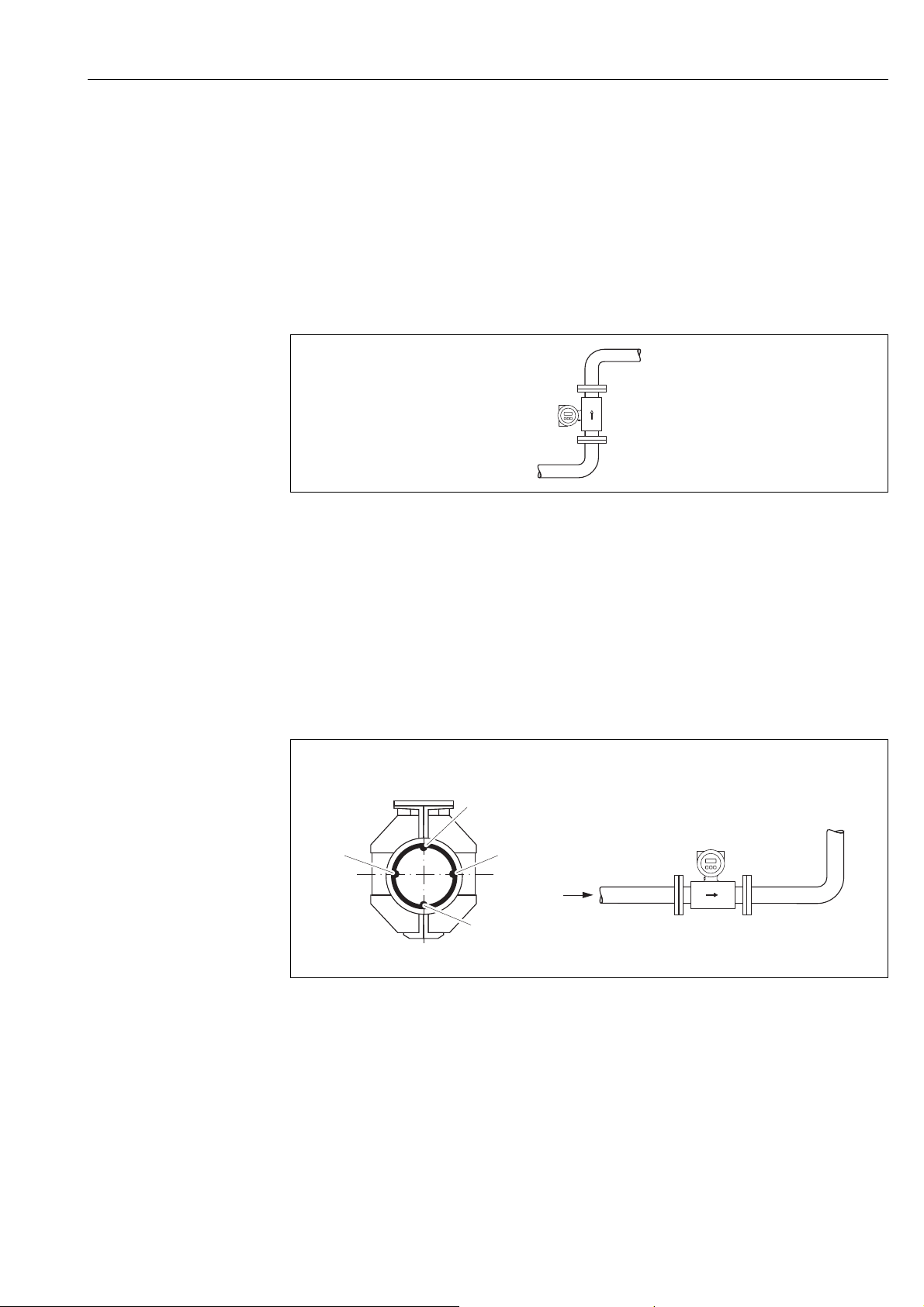
3.2.3 Orientation
An optimum orientation position helps avoid gas and air accumulations and deposits in the
measuring tube. However, Promag offers the additional Empty Pipe Detection (EPD)
function to ensure the detection of partially filled measuring tubes, e.g. in the case of
degassing fluids or varying process pressure.
Vertical orientation
This is the ideal orientation for self-emptying piping systems and for use in conjunction with
Empty Pipe Detection.
A0008158
Fig. 11: Vertical orientation
Horizontal orientation
The measuring electrode plane should be horizontal. This prevents brief insulation of the
two measuring electrodes by entrained air bubbles.
Caution!
"
Empty Pipe Detection functions correctly only when the measuring device is installed
horizontally and the transmitter housing is facing upward ( 11). Otherwise there is no
guarantee that Empty Pipe Detection will respond if the measuring tube is only partially
filled or empty.
Fig. 12: Horizontal orientation
1 EPD electrode for the detection of empty pipes (not with Promag D and Promag H (DN 2 to 8 / ¹⁄₁₂ to ³⁄₈"))
2 Measuring electrodes for signal detection
3 Reference electrode for the potential equalization (not with Promag D and H)
A0003207
Endress+Hauser 13
Page 14
Installation Promag 10
³ 5DNx
³ 2DNx
≥ 0 × DN
L
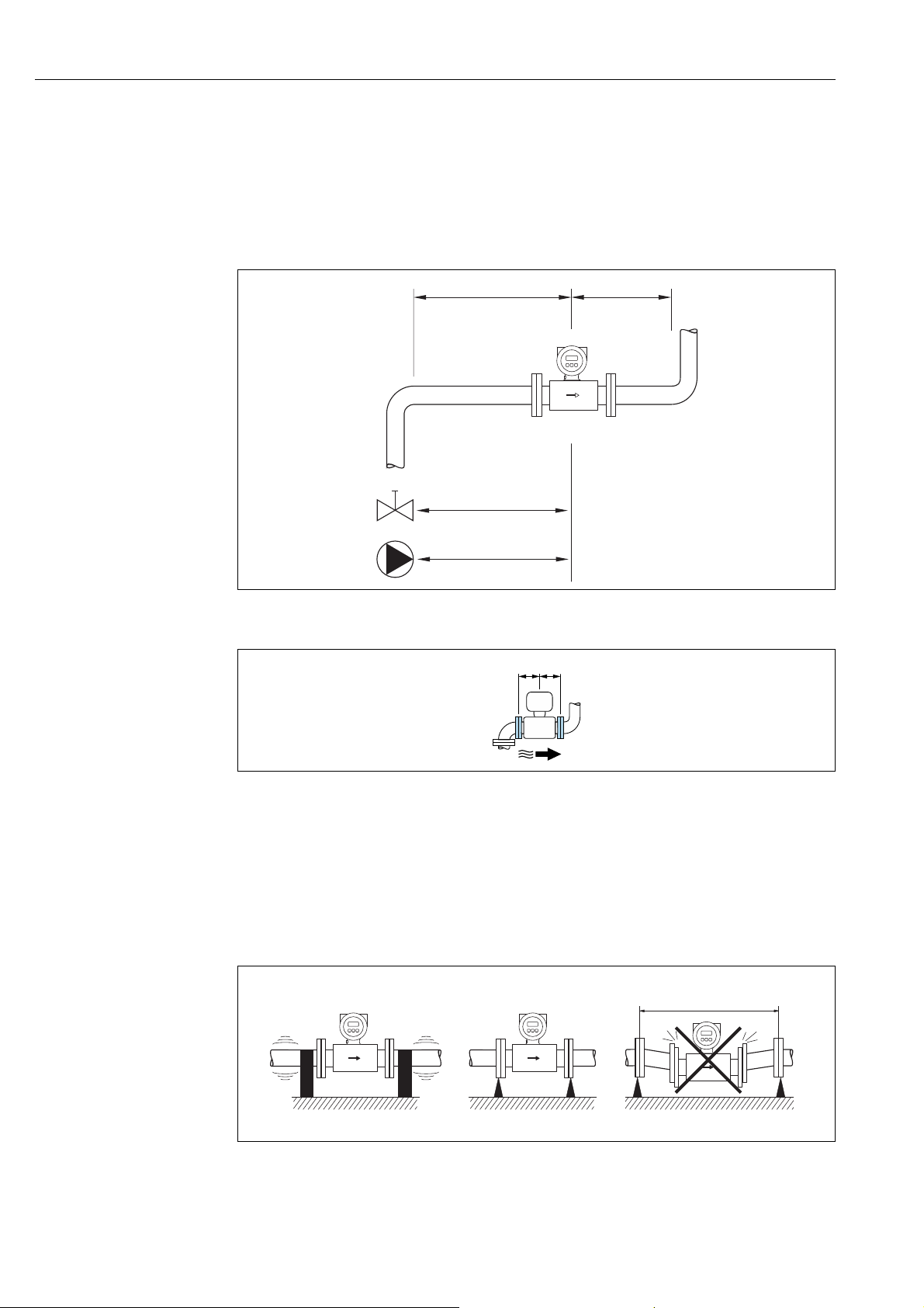
Inlet and outlet run
If possible, install the sensor upstream from fittings such as valves, T-pieces, elbows, etc.
The following inlet and outlet runs must be observed in order to meet accuracy
specifications:
•Inlet run: 5 × DN
•Outlet run: 2 × DN
Fig. 13: Inlet and outlet run standard version
Fig. 14: Optional version: w/o inlet and outlet run
3.2.4 Vibrations
Secure the piping and the sensor if vibration is severe.
Caution!
"
If vibrations are too severe, we recommend the sensor and transmitter be mounted
separately. Information on resistance to vibration and shock can be found on 93.
A0003210
A0032859
Fig. 15: Measures to prevent vibration of the device (L > 10 m (32.8 ft))
14 Endress+Hauser
A0003208
Page 15
Promag 10 Installation
100
10
0.5
d / D
[mbar]
0.6 0.7 0.8 0.9
1 m/s
2 m/s
3 m/s
4 m/s
5 m/s
6 m/s
7 m/s
8 m/s
1
D
d
max. 8°
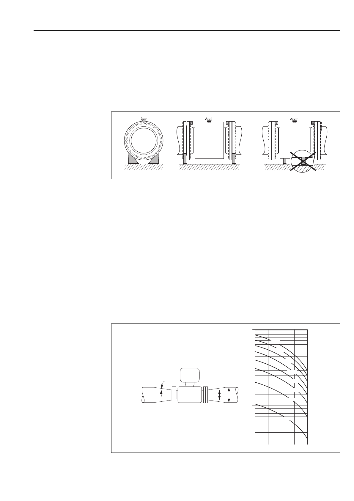
3.2.5 Foundations, supports
If the nominal diameter is DN 350 (14"), mount the sensor on a foundation of adequate
load-bearing strength.
Caution!
"
Risk of damage.
Do not support the weight of the sensor on the metal casing: the casing would buckle and
damage the internal magnetic coils.
A0003209
Fig. 16: Correct support for large nominal diameters (DN ≥ 350 / 14")
!
3.2.6 Adapters
Suitable adapters to DIN EN 545 (double-flange reducers) can be used to install the sensor
in larger-diameter pipes.
The resultant increase in the rate of flow improves measuring accuracy with very slowmoving fluids. The nomogram shown here can be used to calculate the pressure loss caused
by reducers and expanders.
Note!
• The nomogram only applies to liquids of viscosity similar to water.
• For Promag D with threaded connection adapters can not be used
• For Promag H the selection of a pipe with larger diameter for high viscosities of the fluid
may be considered to reduce the pressure loss.
1. Calculate the ratio of the diameters d/D.
2. From the nomogram read off the pressure loss as a function of flow velocity
(downstream from the reduction) and the d/D ratio.
Fig. 17: Pressure loss due to adapters
A0016359
Endress+Hauser 15
Page 16
Installation Promag 10
L
max
[]ft
200 6000
400
200
100
50 100 200
[m]
[ S/cm]μ
L
max
50
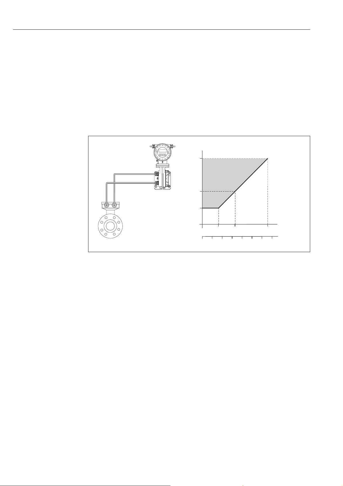
3.2.7 Length of connecting cable
In order to ensure measuring accuracy, comply with the following instructions when
installing the remote version:
• Fix cable run or lay in armored conduit. Cable movements can falsify the measuring signal
especially in the case of low fluid conductivities.
• Route the cable well clear of electrical machines and switching elements.
• Ensure potential equalization between sensor and transmitter, if necessary.
• The permitted connecting cable length L
18). A minimum conductivity of 50 S/cm is needed for all fluids.
• The maximum connecting cable length is 10 m (33 ft) when empty pipe detection (EPD
72) is switched on.
is determined by the fluid conductivity (
max
A0003214
Fig. 18: Permissible cable length for the remote version
Area shaded gray = permitted range
= connecting cable length in [m]
L
max
Fluid conductivity in [μS/cm]
16 Endress+Hauser
Page 17
Promag 10 Installation
≤≤3 ( 10)
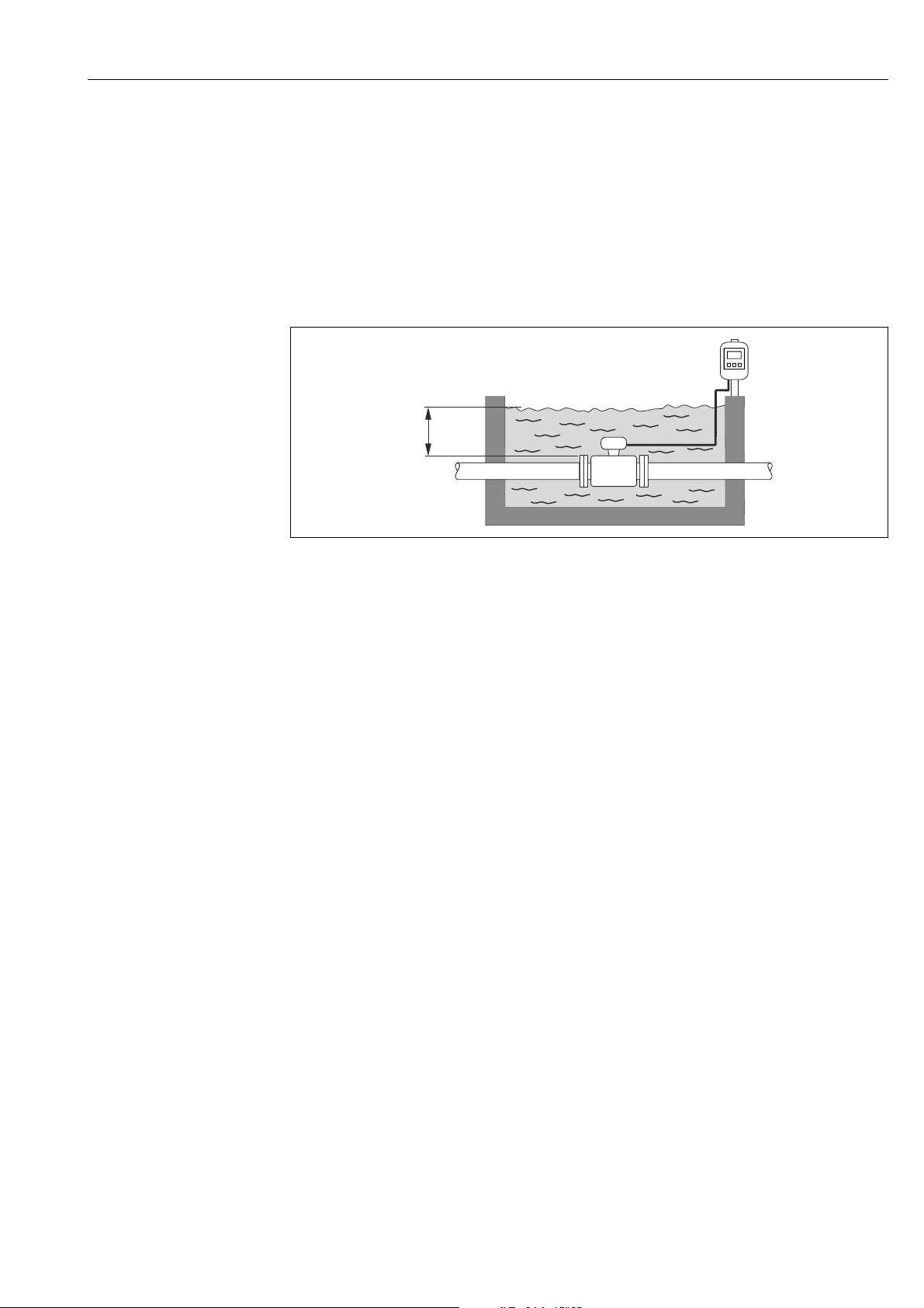
3.2.8 Special mounting instructions
Temporary use in water for sensor Promag L
A remote version in IP67, type 6 is optionally available for temporary use in water up to 168
hours at 3 m (10 ft) or, in exceptional cases, for use up to 48 hours at 10 m (30 ft).
Compared to the degree of protection of standard version IP67, type 4X enclosure, the
version IP67, type 6 enclosure was designed to withstand short-term or temporary
submergence (e.g. flooding).
Fig. 19: Temporary use in water. Engineering unit mm (ft)
A0017296
Endress+Hauser 17
Page 18
Installation Promag 10
5
1
2
3
4
3.3 Installing the measuring device
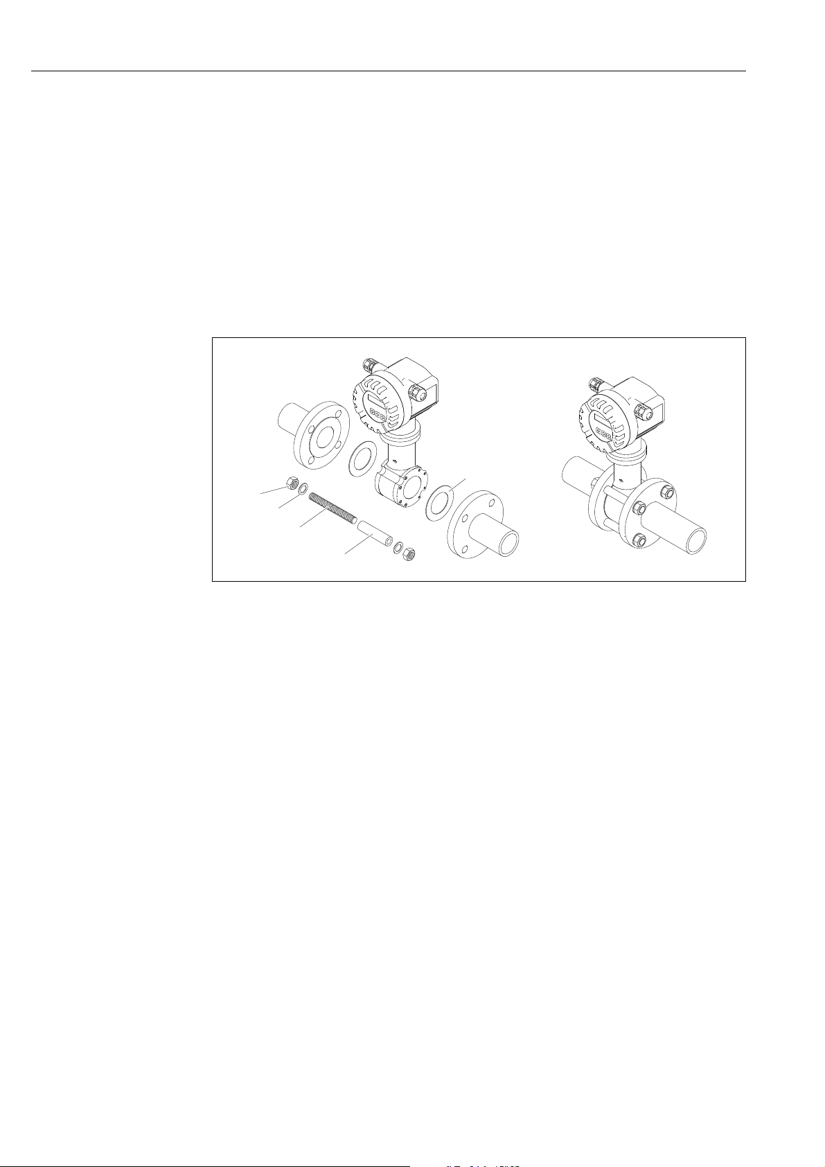
3.3.1 Installing the Promag D sensor as wafer version
The sensor is installed between the pipe flanges with a mounting kit. The device is centered
using recesses on the sensor ( 19).
!
"
Note!
A mounting kit consisting of mounting bolts, seals, nuts and washers can be ordered
separately ( 74). Centering sleeves are provided with the device if they are required for
the installation.
Caution!
When installing the transmitter in the pipe, observe the necessary torques ( 20).
a0010714
Fig. 20: Mounting the sensor Promag D as wafer version
1Nut
2Washer
3 Mounting bolt
4 Centering sleeve
5Seal
Seals
When installing the sensor make sure that the seals used do not project into the pipe crosssection.
Caution!
"
Risk of short circuit! Do not use electrically conductive sealing compounds such as graphite!
An electrically conductive layer could form on the inside of the measuring tube and shortcircuit the measuring signal.
!
18 Endress+Hauser
Note!
Use seals with a hardness rating of 70° Shore A.
Page 19
Promag 10 Installation
1
1
1
1
1
1
1
1
1
1
1
1
2
2
22
3
3
3
3
3
3
3
3
1
1
1
1
1
1
1
1
1
1
1
1
1
1
1
1
1
1
1
1
1
1
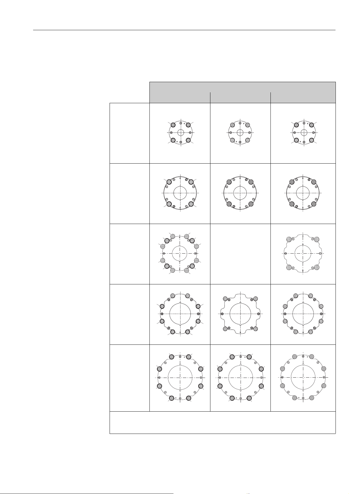
Arrangement of the mounting bolts and centering sleeves
The device is centered using recesses on the sensor. The arrangement of the mounting bolts
and the use of the centering sleeves supplied depend on the nominal diameter, the flange
standard und the pitch circle diameter.
Process connection
EN (DIN) ASME JIS
DN 25 to 40
(1 to 1 ½")
A0010896 A0010824 A0010896
DN 50 (2")
DN 65 (–)
DN 80 (3")
DN 100 (4")
A0010897 A0010825 A0010825
–––––––––––––––––
A0012170
A0010898 A0010827 A0010826
A0012171
Endress+Hauser 19
A0012168 A0012168 A0012169
1 = Mounting bolts with centering sleeves
2 = EN (DIN) flanges: 4-hole with centering sleeves
3 = EN (DIN) flanges: 8-hole without centering sleeves
Page 20
Installation Promag 10
Screw tightening torques (Promag D as wafer version)
Please note the following:
• The tightening torques listed below are for lubricated threads only.
• Always tighten the screws uniformly and in diagonally opposite sequence.
• Overtightening the screws will deform the sealing faces or damage the seals.
• The tightening torques listed below apply only to pipes not subjected to tensile stress.
The tightening torques apply to situations where an EPDM soft material flat seal (e.g. 70°
Shore A) is used.
Promag D as wafer version screw tightening torques, mounting bolts and centering sleeves for
EN 1092-1 (DIN 2501), PN 16
Nominal
diameter
[mm] [mm] [mm] [Nm] [Nm]
25 4 × M12 × 145 54 19 19
40 4 × M16 × 170 68 33 33
50 4 × M16 × 185 82 41 41
65¹ 4 × M16 × 200 92 44 44
65
80 8 × M16 × 225 116 36 36
100 8 × M16 × 260 147 40 40
EN (DIN) flanges: 4-hole with centering sleeves
EN (DIN) flanges: 8-hole without centering sleeves
A centering sleeve is not required. The device is centered directly via the sensor housing.
Mounting bolts
8 × M16 × 200 –
Centering sleeve
length
Tightening torque
with a process flange with a
smooth seal face raised face
29 29
Promag D as wafer version screw tightening torques, mounting bolts and centering sleeves for
JIS B2220, 10K
Nominal
diameter
[mm] [mm] [mm] [Nm] [Nm]
25 4 × M16 × 170 54 24 24
40 4 × M16 × 170 68 32 25
50 4 × M16 × 185 – * 38 30
65 4 × M16 × 200 – * 42 42
80 8 × M16 × 225 – * 36 28
100 8 × M16 × 260 – * 39 37
* A centering sleeve is not required. The device is centered directly via the sensor housing.
Mounting bolts
Centering sleeve
length
Tightening torque
with a process flange with a
smooth seal face raised face
Promag D as wafer version screw tightening torques, mounting bolts and centering sleeves for
ASME B16.5, Class 150
Nominal
diameter
[inch] [inch] [inch] [lbf · ft] [lbf · ft]
1" 4 × UNC ½ " × 5.70" – * 14 7
1 ½" 4 × UNC ½ " × 6.50" – * 21 14
2" 4 × UNC 5/8" × 7.50" – * 30 27
3" 4 × UNC 5/8" × 9.25" – * 31 31
4" 8 × UNC 5/8" × 10.4" 5.79 28 28
* A centering sleeve is not required. The device is centered directly via the sensor housing.
Mounting bolts
Centering sleeve
length
Tightening torque
with a process flange with a
smooth seal face raised face
20 Endress+Hauser
Page 21
Promag 10 Installation
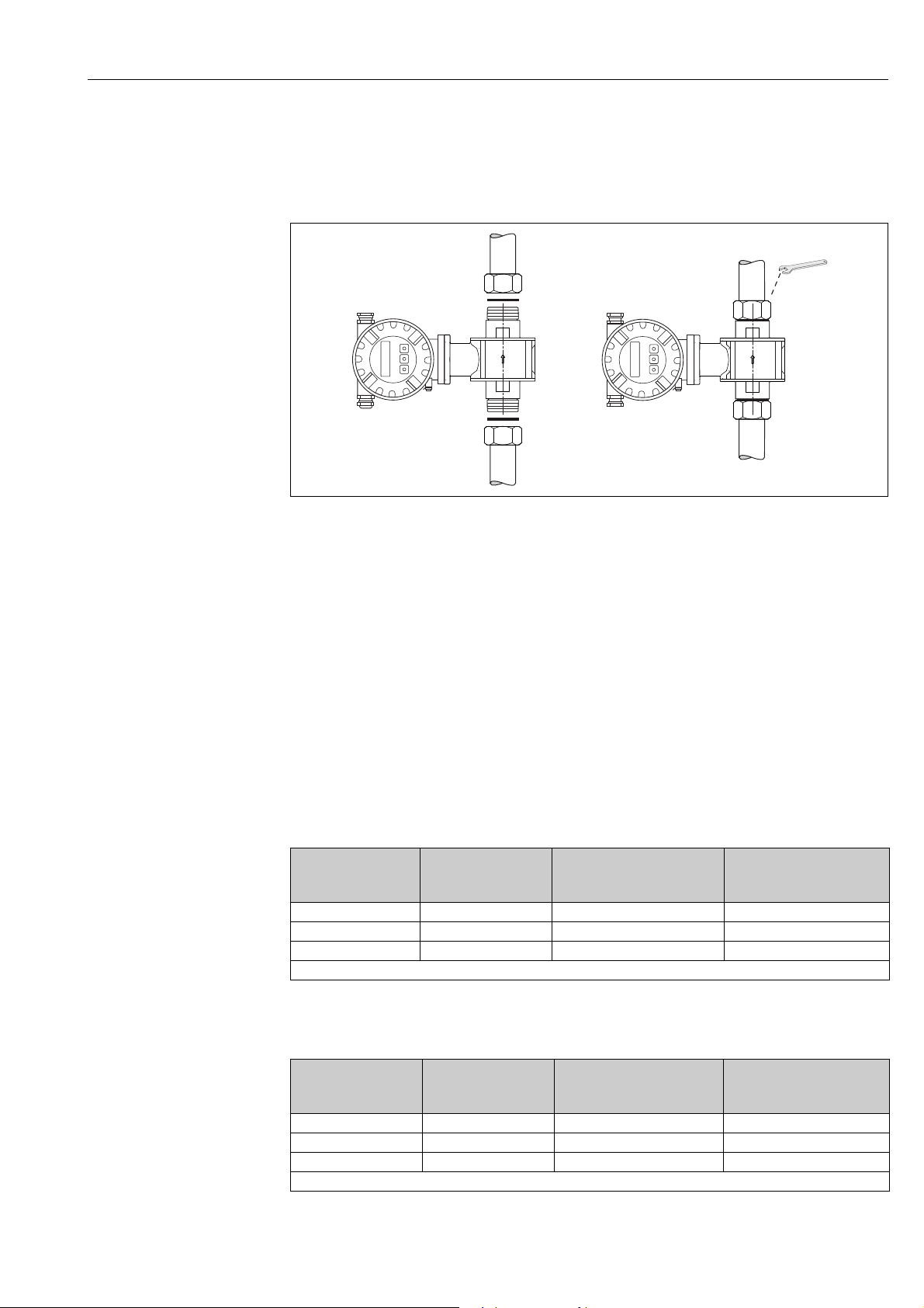
3.3.2 Installing the Promag D sensor with threaded connection
The sensor can be installed into the pipe with common threaded connections.
Caution!
"
When installing the transmitter in the pipe, observe the necessary torques ( 20).
A0029328
Fig. 21: Installing the Promag D sensor with threaded connection
Seals
The purchaser is responsible for the choice of the seals. Common seals can be used for the
threaded connections.
Caution!
"
Risk of short circuit! Do not use electrically conductive sealing compounds such as graphite!
An electrically conductive layer could form on the inside of the measuring tube and shortcircuit the measuring signal.
Screw tightening torques (Promag D with threaded connection)
The tightening torques listed below are for lubricated threads only.
Promag D with threaded connection screw tightening torques, mounting bolts and width
across flat for EN 1092-1 (DIN 2501), PN 16
Nominal diameter
[mm] [mm/inch] [Nm]
25 G 1" 28/1.1 20
40 G 1 ½" 50/1.97 50
50 G 2" 60/2.36 90
The purchaser is responsible for the choice of the seals
Threaded
connection
Width across flat Max. tightening torque
Promag D with threaded connection screw tightening torques, mounting bolts and width
across flat for ASME B16.5, Class 150
Nominal diameter
[in] [mm/inch] [Nm]
1" NPT 1" 28/1.1 20
1 ½" NPT 1 ½" 50/1.97 50
2" NPT 2" 60/2.36 90
The purchaser is responsible for the choice of the seals
Threaded
connection
Width across flat Max. tightening torque
Endress+Hauser 21
Page 22
Installation Promag 10
3.3.3 Installing the Promag E sensor
Caution!
"
• The protective covers mounted on the two sensor flanges guard the PTFE, which is turned
over the flanges. Consequently, do not remove these covers until immediately before the
sensor is installed in the pipe.
• The covers must remain in place while the device is in storage.
• Make sure that the lining is not damaged or removed from the flanges.
!
Note!
Bolts, nuts, seals, etc. are not included in the scope of supply and must be supplied by the
customer.
The sensor is designed for installation between the two piping flanges.
• Observe in any case the necessary screw tightening torques on 23
• If grounding disks are used, follow the mounting instructions which will be enclosed with
the shipment
Fig. 22: Installing the Promag E sensor
Seals
Comply with the following instructions when installing seals:
• PTFE lining No seals are required!
• For DIN flanges, use only seals according to EN 1514-1.
• Make sure that the seals do not protrude into the piping cross-section.
Caution!
"
Risk of short circuit! Do not use electrically conductive sealing compounds such as graphite!
An electrically conductive layer could form on the inside of the measuring tube and shortcircuit the measuring signal.
Ground cable
• If necessary, special ground cables for potential equalization can be ordered as an
accessory ( 74).
• Information on potential equalization and detailed mounting instructions for the use of
ground cables can be found on 54
a0004296
22 Endress+Hauser
Page 23

Promag 10 Installation
Tightening torques for threaded fasteners (Promag E)
Please note the following:
• The tightening torques listed below are for lubricated threads only.
• Always tighten the screws uniformly and in diagonally opposite sequence.
• Overtightening the screws will deform the sealing faces or damage the seals.
• The tightening torques listed below apply only to pipes not subjected to tensile stress.
Tightening torques for:
•EN (DIN) 23
•ASME 24
•JIS 24
Promag E screw tightening torques for EN 1092-1 (DIN 2501), PN 6/10/16/40
Nominal
diameter
[mm]
15 PN 40 4 × M 12 16 11
25 PN 40 4 × M 12 18 26
32 PN 40 4 × M 16 18 41
40 PN 40 4 × M 16 18 52
50 PN 40 4 × M 16 20 65
65 * PN 16 8 × M 16 18 43
80 PN 16 8 × M 16 20 53
100 PN 16 8 × M 16 20 57
125 PN 16 8 × M 16 22 75
150 PN 16 8 × M 20 22 99
200 PN 10 8 × M 20 24 141
200 PN 16 12 × M 20 24 94
250 PN 10 12 × M 20 26 110
250 PN 16 12 × M 24 26 131
300 PN 10 12 × M 20 26 125
300 PN 16 12 × M 24 28 179
350 PN 6 12 × M 20 22 200
350 PN 10 16 × M 20 26 188
350 PN 16 16 × M 24 30 254
400 PN 6 16 × M 20 22 166
400 PN 10 16 × M 24 26 260
400 PN 16 16 × M 27 32 330
450 PN 6 16 × M 20 22 202
450 PN 10 20 × M 24 28 235
450 PN 16 20 × M 27 40 300
500 PN 6 20 × M 20 24 176
500 PN 10 20 × M 24 28 265
500 PN 16 20 × M 30 34 448
600 PN 6 20 × M 24 30 242
600 PN 10 20 × M 27 28 345
600 * PN 16 20 × M 33 36 658
* Designed acc. to EN 1092-1 (not to DIN 2501)
EN (DIN)
Pressure rating
Threaded
fasteners
Flange thickness
[mm]
Max. tightening
torque PTFE
[Nm]
Promag E screw tightening torques for EN 1092-1, PN 6/10/16, P245GH/stainless-steel;
Calculated according to EN 1591-1:2014 for flanges according to EN 1092-1:2013
Nominal
diameter
[mm]
350 PN 10 16 × M 20 26 60
EN (DIN)
Pressure rating
Threaded
fasteners
Flange thickness
[mm]
Nom. tightening torque
PTFE
[Nm]
Endress+Hauser 23
Page 24

Installation Promag 10
Nominal
diameter
[mm]
350 PN 16 16 × M 24 30 115
400 PN 10 16 × M 24 26 90
400 PN 16 16 × M 27 32 155
450 PN 10 20 × M 24 28 90
450 PN 16 20 × M 27 34 155
500 PN 10 20 × M 24 28 100
500 PN 16 20 × M 30 36 205
600 PN 10 20 × M 27 30 150
600 PN 16 20 × M 33 40 310
EN (DIN)
Pressure rating
Threaded
fasteners
Flange thickness
[mm]
Nom. tightening torque
PTFE
[Nm]
Promag E screw tightening torques for ASME B16.5, Class 150
Nominal diameter ASME Threaded fasteners Max. tightening torque
PTFE
[mm] [inch] [Nm] [lbf · ft]
15 ½" Class 150 4 × ½" 6 4
25 1" Class 150 4 × ½" 11 8
40 1 ½" Class 150 4 × ½" 24 18
50 2" Class 150 4 × 5/8" 47 35
80 3" Class 150 4 × 5/8" 79 58
100 4" Class 150 8 × 5/8" 56 41
150 6" Class 150 8 × ¾" 106 78
200 8" Class 150 8 × ¾" 143 105
250 10" Class 150 12 × 7/8" 135 100
300 12" Class 150 12 × 7/8" 178 131
350 14" Class 150 12 × 1" 260 192
400 16" Class 150 16 × 1" 246 181
450 18" Class 150 16 × 1 ¹⁄" 371 274
500 20" Class 150 20 × 1 ¹⁄" 341 252
600 24" Class 150 20 × 1 ¼" 477 352
Pressure rating
Promag E screw tightening torques for JIS B2220, 10/20K
Nominal diameter JIS Threaded fasteners Max. tightening torque PTFE
[mm] Pressure rating [Nm]
15 20K 4 × M 12 16
25 20K 4 × M 16 32
32 20K 4 × M 16 38
40 20K 4 × M 16 41
50 10K 4 × M 16 54
65 10K 4 × M 16 74
80 10K 8 × M 16 38
100 10K 8 × M 16 47
125 10K 8 × M 20 80
150 10K 8 × M 20 99
200 10K 12 × M 20 82
250 10K 12 × M 22 133
300 10K 16 × M 22 99
24 Endress+Hauser
Page 25
Promag 10 Installation
A
B
C
DN 2…25
( / "…1")
1
12
DN 40…100
(1½"…4")
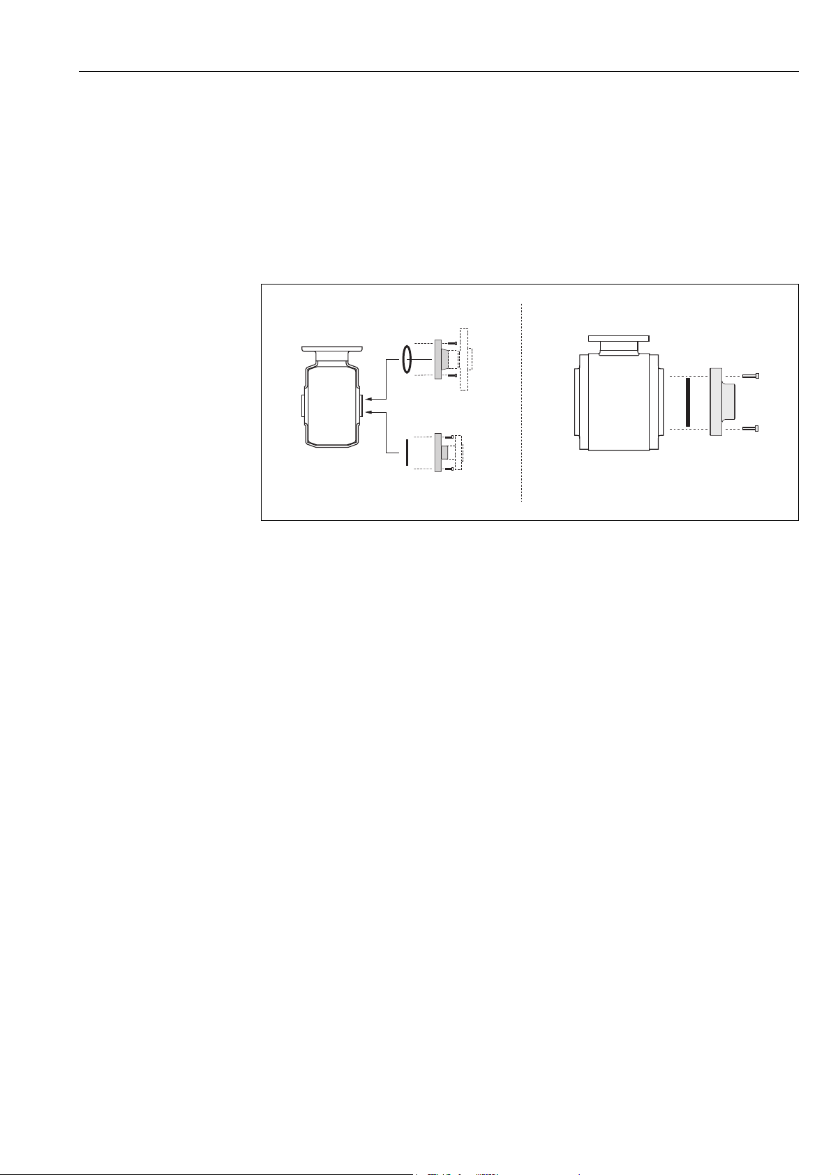
3.3.4 Installing the Promag H sensor
The sensor is supplied to order, with or without pre-installed process connections. Preinstalled process connections are secured to the sensor with 4 or 6 hex-head threaded
fasteners.
Caution!
"
The sensor might require support or additional attachments, depending on the application
and the length of the piping run. When plastic process connections are used, the sensor must
be additionally supported mechanically. A wall-mounting kit can be ordered separately from
Endress+Hauser as an accessory ( 74).
a0004301
Fig. 23: Promag H process connections
A = DN 2 to 25 / process connections with O-ring
– Flanges (EN (DIN), ASME, JIS ),
–External thread
B = DN 2 to 25 / process connections with aseptic gasket seal
– Weld nipples (EN 10357 (DIN 11850), ODT/SMS)
– Tri-Clamp L14AM7
– Coupling (DIN 11851, DIN 11864-1, SMS 1145 (only DN 25)
– Flange DIN 11864-2
C = DN 40 to 150 / process connections with aseptic gasket seal
– Weld nipples (EN 10357 (DIN 11850), ODT/SMS)
– Tri-Clamp L14AM7
– Coupling (DIN 11851, DIN 11864-1, SMS 1145)
– Flange DIN 11864-2
Seals
When installing the process connections, make sure that the seals are clean and correctly
centered.
Caution!
"
• With metal process connections, you must fully tighten the screws. The process
connection forms a metallic connection with the sensor, which ensures a defined
compression of the seal.
• With plastic process connections, note the max. torques for lubricated threads (7 Nm / 5.2
lbf ft). With plastic flanges, always use seals between connection and counter flange.
• The seals must be replaced periodically, depending on the application, particularly in the
case of gasket seals (aseptic version)!
The period between changes depends on the frequency of cleaning cycles, the cleaning
temperature and the fluid temperature. Replacement seals can be ordered as accessories
74.
Endress+Hauser 25
Page 26

Installation Promag 10
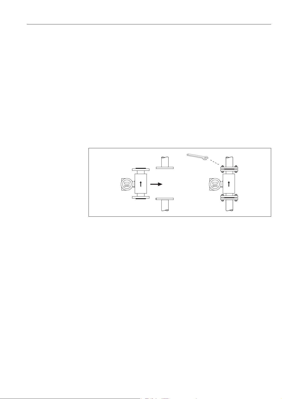
Welding the transmitter into the piping (weld nipples)
Caution!
"
Risk of destroying the measuring electronics. Make sure that the welding machine is not
grounded via the sensor or the transmitter.
1. Tack-weld the sensor into the pipe. A suitable welding jig can be ordered separately as
an accessory ( 74).
2. Loosen the screws on the process connection flange and remove the sensor, complete
with the seal, from the pipe.
3. Weld the process connection to the pipe.
4. Reinstall the sensor in the pipe. Make sure that everything is clean and that the seal is
correctly seated.
!
Note!
• If thin-walled foodstuffs pipes are not welded correctly, the heat could damage the
installed seal. It is therefore advisable to remove the sensor and the seal prior to welding.
• The pipe has to be spread approximately 8 mm to permit disassembly.
Cleaning with pigs
If pigs are us ed for cleaning, it is essential to take the inside diameters of the measuri ng tube
and process connection into account. All the dimensions and lengths of the sensor and
transmitter are provided in the separate documentation "Technical Documentation".
26 Endress+Hauser
Page 27
Promag 10 Installation
3.3.5 Installing the Promag L sensor
Caution!
"
• The protective covers mounted on the two sensor flanges (DN 25 to 300 / 1 to 12") are
used to hold the lap joint flanges in place and to protect the PTFE liner during
transportation. Consequently, do not remove these covers until immediately before the
sensor is installed in the pipe.
• The covers must remain in place while the device is in storage.
• Make sure that the lining is not damaged or removed from the flanges.
!
Note!
Bolts, nuts, seals, etc. are not included in the scope of supply and must be supplied by the
customer.
The sensor is designed for installation between the two piping flanges.
• Observe in any case the necessary screw tightening torques on 28
• If grounding disks are used, follow the mounting instructions which will be enclosed with
the shipment
• To comply with the device specification, a concentrical installation in the measuring
section is required
Fig. 24: Installing the Promag L sensor
Seals
Comply with the following instructions when installing seals:
• Hard rubber lining additional seals are always necessary.
• Polyurethane lining no seals are required.
• PTFE lining no seals are required.
• For DIN flanges, use only seals according to EN 1514-1.
• Make sure that the seals do not protrude into the piping cross-section.
Caution!
"
Risk of short circuit!
Do not use electrically conductive sealing compounds such as graphite! An electrically
conductive layer could form on the inside of the measuring tube and short-circuit the
measuring signal.
Ground cable
• If necessary, special ground cables for potential equalization can be ordered as an
accessory ( 74).
• Information on potential equalization and detailed mounting instructions for the use of
ground cables can be found on 54.
a0004296
Endress+Hauser 27
Page 28

Installation Promag 10
Screw tightening torques (Promag L)
Please note the following:
• The tightening torques listed below are for lubricated threads only.
• Always tighten the screws uniformly and in diagonally opposite sequence.
• Overtightening the screws will deform the sealing faces or damage the seals.
• The tightening torques listed below apply only to pipes not subjected to tensile stress.
Promag L screw tightening torques for EN 1092-1 (DIN 2501), PN 6/10/16
Nominal EN (DIN) Threaded Flange Max. tightening torques
diamter Pressure rating fasteners thickness Hard rubber Polyurethane PTFE
[mm] [mm] [Nm] [Nm] [Nm]
25 PN 10/16 4 × M 12 18 - 6 11
32 PN 10/16 4 × M 16 18 - 16 27
40 PN 10/16 4 × M 16 18 - 16 29
50 PN 10/16 4 × M 16 18 - 15 40
65* PN 10/16 8 × M 16 18 - 10 22
80 PN 10/16 8 × M 16 20 - 15 30
100 PN 10/16 8 × M 16 20 - 20 42
125 PN 10/16 8 × M 16 22 - 30 55
150 PN 10/16 8 × M 20 22 - 50 90
200 PN 16 12 × M 20 24 - 65 87
250 PN 16 12 × M 24 26 - 126 151
300 PN 16 12 × M 24 28 - 139 177
350 PN 6 12 × M 20 22 111 120 350 PN 10 16 × M 20 26 112 118 350 PN 16 16 × M 24 30 152 165 400 PN 6 16 × M 20 22 90 98 400 PN 10 16 × M 24 26 151 167 400 PN 16 16 × M 27 32 193 215 450 PN 6 16 × M 20 22 112 126 450 PN 10 20 × M 24 28 153 133 500 PN 6 20 × M 20 24 119 123 500 PN 10 20 × M 24 28 155 171 500 PN 16 20 × M 30 34 275 300 600 PN 6 20 × M 24 30 139 147 600 PN 10 20 × M 27 28 206 219 -
600* PN 16 20 × M 33 36 415 443 -
700 PN 6 24 × M 24 24 148 139 700 PN 10 24 × M 27 30 246 246 700 PN 16 24 × M 33 36 278 318 800 PN 6 24 × M 27 24 206 182 800 PN 10 24 × M 30 32 331 316 800 PN 16 24 × M 36 38 369 385 900 PN 6 24 × M 27 26 230 637 900 PN 10 28 × M 30 34 316 307 900 PN 16 28 × M 36 40 353 398 -
1000 PN 6 28 × M 27 26 218 208 1000 PN 10 28 × M 33 34 402 405 1000 PN 16 28 × M 39 42 502 518 1200 PN 6 32 × M 30 28 319 299 1200 PN 10 32 × M 36 38 564 568 1200 PN 16 32 × M 45 48 701 753 1400 PN 6 36 × M 33 32 430 - 1400 PN 10 36 × M 39 42 654 - 1400 PN 16 36 × M 45 52 729 - 1600 PN 6 40 × M 33 34 440 - 1600 PN 10 40 × M 45 46 946 - -
28 Endress+Hauser
Page 29

Promag 10 Installation
Nominal EN (DIN) Threaded Flange Max. tightening torques
diamter Pressure rating fasteners thickness Hard rubber Polyurethane PTFE
[mm] [mm] [Nm] [Nm] [Nm]
1600 PN 16 40 × M 52 58 1007 - 1800 PN 6 44 × M 36 36 547 - 1800 PN 10 44 × M 45 50 961 - 1800 PN 16 44 × M 52 62 1108 - 2000 PN 6 48 × M 39 38 629 - 2000 PN 10 48 × M 45 54 1047 - 2000 PN 16 48 × M 56 66 1324 - 2200 PN 6 52 × M 39 42 698 - 2200 PN 10 52 × M 52 58 1217 - 2400 PN 6 56 × M 39 44 768 - 2400 PN 10 56 × M 52 62 1229 - -
* Designed acc. to EN 1092-1 (not to DIN 2501)
Promag L screw tightening torques for EN 1092-, PN 6/10/16, P245GH/stainless-steel;
Calculated according to EN 1591-1:2014 for flanges according to EN 1092-1:2013
Nominal
diameter
[mm] [mm] [Nm] [Nm]
350 PN 6 12 × M 20 22 60 75
350 PN 10 16 × M 20 26 70 80
400 PN 6 16 × M 20 22 65 70
400 PN 10 16 × M 24 26 100 120
400 PN 16 16 × M 27 32 175 190
450 PN 6 16 × M 20 22 70 90
450 PN 10 20 × M 24 28 100 110
500 PN 6 20 × M 20 24 65 70
500 PN 10 20 × M 24 28 110 120
500 PN 16 20 × M 30 36 225 235
600 PN 6 20 × M 24 30 105 105
600 PN 10 20 × M 27 30 165 160
600 PN 16 20 × M 33 40 340 340
700 PN 6 24 × M 24 30 110 110
700 PN 10 24 × M 27 35 190 190
700 PN 16 24 × M 33 40 340 340
800 PN 6 24 × M 27 30 145 145
800 PN 10 24 × M 30 38 260 260
800 PN 16 24 × M 36 41 465 455
900 PN 6 24 × M 27 34 170 180
900 PN 10 28 × M 30 38 265 275
900 PN 16 28 × M 36 48 475 475
1000 PN 6 28 × M 27 38 175 185
1000 PN 10 28 × M 33 44 350 360
1000 PN 16 28 × M 39 59 630 620
1200 PN 6 32 × M 30 42 235 250
1200 PN 10 32 × M 36 55 470 480
1200 PN 16 32 × M 45 78 890 900
1400 PN 6 36 × M 33 56 300 1400 PN 10 36 × M 39 65 600 1400 PN 16 36 × M 45 84 1050 1600 PN 6 40 × M 33 63 340 1600 PN 10 40 × M 45 75 810 1600 PN 16 40 × M 52 102 1420 1800 PN 6 44 × M 36 69 430 -
EN(DIN)
pressure rating
Threaded
fastener
Flange
thickness
Nom. tightening torques
Hard rubber Polyurethane
Endress+Hauser 29
Page 30

Installation Promag 10
Nominal
diameter
[mm] [mm] [Nm] [Nm]
1800 PN 10 44 × M 45 85 920 1800 PN 16 44 × M 52 110 1600 2000 PN 6 48 × M 39 74 530 2000 PN 10 48 × M 45 90 1040 2000 PN 16 48 × M 56 124 1900 2200 PN 6 52 × M 39 81 580 2200 PN 10 52 × M 52 100 1290 2400 PN 6 56 × M 39 87 650 2400 PN 10 56 × M 52 110 1410 -
EN(DIN)
pressure rating
Threaded
fastener
Flange
thickness
Nom. tightening torques
Hard rubber Polyurethane
Promag L screw tightening torques for ASME B16.5, Class 150
Nominal diameter ASME Threaded Max. tightening torque
Pressure rating fasteners Hard rubber Polyurethane PTFE
[mm] [inch] [Nm] [lbf · ft] [Nm] [lbf · ft] [Nm] [lbf · ft]
25 1" Class 150 4 × 5/8" - - 5 4 14 13
40 1 ½" Class 150 8 × 5/8" - - 10 17 21 15
50 2" Class 150 4 × 5/8" - - 15 11 40 29
80 3" Class 150 4 × 5/8" - - 25 18 65 48
100 4" Class 150 8 × 5/8" - - 20 15 44 32
150 6" Class 150 8 × ¾" - - 45 33 90 66
200 8" Class 150 8 × ¾" - - 65 48 87 64
250 10" Class 150 12 × 7/8" - - 126 93 151 112
300 12" Class 150 12 × 7/8" - - 146 108 177 131
350 14" Class 150 12 × 1" 135 100 158 117 - 400 16" Class 150 16 × 1" 128 94 150 111 - 450 18" Class 150 16 × 1 ¹⁄" 204 150 234 173 - -
500 20" Class 150 20 × 1 ¹⁄" 183 135 217 160 - -
600 24" Class 150 20 × 1 ¼" 268 198 307 226 - -
Promag L screw tightening torques for AWWA, Class D
Nominal diameter AWWA Threaded Max. tightening torque
Pressure rating fasteners Hart rubber Polyurethane PTFE
[mm] [inch] [Nm] [lbf · ft] [Nm] [lbf · ft] [Nm] [lbf · ft]
700 28" Class D 28 × 1 ¼" 247 182 292 215 - 750 30" Class D 28 × 1 ¼" 287 212 302 223 - 800 32" Class D 28 × 1 ½" 394 291 422 311 - 900 36" Class D 32 × 1 ½" 419 309 430 317 - -
1000 40" Class D 36 × 1 ½" 420 310 477 352 - 1050 42" Class D 36 × 1 ½" 528 389 518 382 - 1200 48" Class D 44 × 1 ½" 552 407 531 392 - -
Promag L screw tightening torques for AS 2129, Table E
Nominal diameter AS 2129 Threaded Max. tightening torque
Pressure rating fasteners Hard rubber Polyurethane PTFE
[mm] [Nm] [Nm] [Nm]
350 Table E 12 × M 24 203 - 400 Table E 12 × M 24 226 - 450 Table E 16 × M 24 226 - 500 Table E 16 × M 24 271 - 600 Table E 16 × M 30 439 - 700 Table E 20 × M 30 355 - 750 Table E 20 × M 30 559 - -
30 Endress+Hauser
Page 31

Promag 10 Installation
Nominal diameter AS 2129 Threaded Max. tightening torque
Pressure rating fasteners Hard rubber Polyurethane PTFE
[mm] [Nm] [Nm] [Nm]
800 Table E 20 × M 30 631 - -
900 Table E 24 × M 30 627 - 1000 Table E 24 × M 30 634 - 1200 Table E 32 × M 30 727 - -
Promag L screw tightening torques for AS 4087, PN16
Nominal diameter AS 4087 Threaded Max. tightening torque
Pressure rating fasteners Hard rubber Polyurethane PTFE
[mm] [Nm] [Nm] [Nm]
350 PN 16 12 × M 24 203 - 375 PN 16 12 × M 24 137 - 400 PN 16 12 × M 24 226 - 450 PN 16 12 × M 24 301 - 500 PN 16 16 × M 24 271 - 600 PN 16 16 × M 27 393 - 700 PN 16 20 × M 27 330 - 750 PN 16 20 × M 30 529 - 800 PN 16 20 × M 33 631 - -
900 PN 16 24 × M 33 627 - 1000 PN 16 24 × M 33 595 - 1200 PN 16 32 × M 33 703 - -
Endress+Hauser 31
Page 32

Installation Promag 10
3.3.6 Installing the Promag P sensor
Caution!
"
• The protective covers mounted on the two sensor flanges guard the PTFE, which is turned
over the flanges. Consequently, do not remove these covers until immediately before the
sensor is installed in the pipe.
• The covers must remain in place while the device is in storage.
• Make sure that the lining is not damaged or removed from the flanges.
!
Note!
Bolts, nuts, seals, etc. are not included in the scope of supply and must be supplied by the
customer.
The sensor is designed for installation between the two piping flanges.
• Observe in any case the necessary screw tightening torques on 32
• If grounding disks are used, follow the mounting instructions which will be enclosed with
the shipment
Fig. 25: Installing the Promag P sensor
Seals
Comply with the following instructions when installing seals:
• PTFE lining No seals are required!
• For DIN flanges, use only seals according to EN 1514-1.
• Make sure that the seals do not protrude into the piping cross-section.
Caution!
"
Risk of short circuit! Do not use electrically conductive sealing compounds such as graphite!
An electrically conductive layer could form on the inside of the measuring tube and shortcircuit the measuring signal.
Ground cable
• If necessary, special ground cables for potential equalization can be ordered as an
accessory ( 74).
• Information on potential equalization and detailed mounting instructions for the use of
ground cables can be found on 54
Tightening torques for threaded fasteners (Promag P)
Please note the following:
• The tightening torques listed below are for lubricated threads only.
• Always tighten the screws uniformly and in diagonally opposite sequence.
• Overtightening the screws will deform the sealing faces or damage the seals.
• The tightening torques listed below apply only to pipes not subjected to tensile stress.
a0004296
32 Endress+Hauser
Page 33

Promag 10 Installation
Tightening torques for:
•EN (DIN) 33
•ASME 34
•JIS 34
• AS 2129 35
• AS 4087 35
Promag P screw tightening torques for EN 1092-1 (DIN 2501), PN 10/16/25/40
Nominal diameter EN (DIN)
Pressure rating
bar
[mm] [mm] [Nm]
25 PN 40 4 × M 12 18 26
32 PN 40 4 × M 16 18 41
40 PN 40 4 × M 16 18 52
50 PN 40 4 × M 16 20 65
65 * PN 16 8 × M 16 18 43
65 PN 40 8 × M 16 22 43
80 PN 16 8 × M 16 20 53
80 PN 40 8 × M 16 24 53
100 PN 16 8 × M 16 20 57
100 PN 40 8 × M 20 24 78
125 PN 16 8 × M 16 22 75
125 PN 40 8 × M 24 26 111
150 PN 16 8 × M 20 22 99
150 PN 40 8 × M 24 28 136
200 PN 10 8 × M 20 24 141
200 PN 16 12 × M 20 24 94
200 PN 25 12 × M 24 30 138
250 PN 10 12 × M 20 26 110
250 PN 16 12 × M 24 26 131
250 PN 25 12 × M 27 32 200
300 PN 10 12 × M 20 26 125
300 PN 16 12 × M 24 28 179
300 PN 25 16 × M 27 34 204
350 PN 10 16 × M 20 26 188
350 PN 16 16 × M 24 30 254
350 PN 25 16 × M 30 38 380
400 PN 10 16 × M 24 26 260
400 PN 16 16 × M 27 32 330
400 PN 25 16 × M 33 40 488
450 PN 10 20 × M 24 28 235
450 PN 16 20 × M 27 40 300
450 PN 25 20 × M 33 46 385
500 PN 10 20 × M 24 28 265
500 PN 16 20 × M 30 34 448
500 PN 25 20 × M 33 48 533
600 PN 10 20 × M 27 28 345
600 * PN 16 20 × M 33 36 658
600 PN 25 20 × M 36 58 731
* Designed acc. to EN 1092-1 (not to DIN 2501)
Threaded
fasteners
Flange
thickness
Max. tightening
torque
PTFE
Endress+Hauser 33
Page 34

Installation Promag 10
Promag P screw tightening torques for EN 1092-1, PN 10/16/25, P245GH/stainless-steel;
Calculated according to EN 1591-1:2014 for flanges according to EN 1092-1:2013
Nominal
diamter
[mm]
350 PN 10 16 × M 20 26 60
350 PN 16 16 × M 24 30 115
350 PN 25 16 × M 30 38 220
400 PN 10 16 × M 24 26 90
400 PN 16 16 × M 27 32 155
400 PN 25 16 × M 33 40 290
450 PN 10 20 × M 24 28 90
450 PN 16 20 × M 27 34 155
450 PN 25 20 × M 33 46 290
500 PN 10 20 × M 24 28 100
500 PN 16 20 × M 30 36 205
500 PN 25 20 × M 33 48 345
600 PN 10 20 × M 27 30 150
600 PN 16 20 × M 33 40 310
600 PN 25 20 × M 36 48 500
EN (DIN)
pressure rating
Threaded
fasteners
Flange thickness
[mm]
Nom. tightening torques
PTFE
[Nm]
Promag P screw tightening torques for ASME B16.5, Class 150/300
Nominal diameter ASME Threaded fasteners Max. tightening torque
PTFE
[mm] [inch] [Nm] [lbf · ft]
25 1" Class 150 4 × ½" 11 8
25 1" Class 300 4 × 5/8" 14 10
40 1 ½" Class 150 4 × ½" 24 18
40 1 ½" Class 300 4 × ¾" 34 25
50 2" Class 150 4 × 5/8" 47 35
50 2" Class 300 8 × 5/8" 23 17
80 3" Class 150 4 × 5/8" 79 58
80 3" Class 300 8 × ¾" 47 35
100 4" Class 150 8 × 5/8" 56 41
100 4" Class 300 8 × ¾" 67 49
150 6" Class 150 8 × ¾" 106 78
150 6" Class 300 12 × ¾" 73 54
200 8" Class 150 8 × ¾" 143 105
250 10" Class 150 12 × 7/8" 135 100
300 12" Class 150 12 × 7/8" 178 131
350 14" Class 150 12 × 1" 260 192
400 16" Class 150 16 × 1" 246 181
450 18" Class 150 16 × 1 ¹⁄" 371 274
500 20" Class 150 20 × 1 ¹⁄" 341 252
600 24" Class 150 20 × 1 ¼" 477 352
Pressure rating
Promag P screw tightening torques for JIS B2220, 10/20K
Nominal diameter JIS Pressure Threaded fasteners Max. tightening torque PTFE
[mm] rating [Nm]
25 10K 4 × M 16 32
25 20K 4 × M 16 32
32 10K 4 × M 16 38
32 20K 4 × M 16 38
40 10K 4 × M 16 41
40 20K 4 × M 16 41
50 10K 4 × M 16 54
34 Endress+Hauser
Page 35

Promag 10 Installation
Nominal diameter JIS Pressure Threaded fasteners Max. tightening torque PTFE
[mm] rating [Nm]
50 20K 8 × M 16 27
65 10K 4 × M 16 74
65 20K 8 × M 16 37
80 10K 8 × M 16 38
80 20K 8 × M 20 57
100 10K 8 × M 16 47
100 20K 8 × M 20 75
125 10K 8 × M 20 80
125 20K 8 × M 22 121
150 10K 8 × M 20 99
150 20K 12 × M 22 108
200 10K 12 × M 20 82
200 20K 12 × M 22 121
250 10K 12 × M 22 133
250 20K 12 × M 24 212
300 10K 16 × M 22 99
300 20K 16 × M 24 183
Promag P tightening torques for JIS B2220, 10/20K
Nominal
diameter
[mm] [Nm] [Nm]
350 10K 16 × M 22 109 109
350 20K 16 × M 30 x3 217 217
400 10K 16 × M 24 163 163
400 20K 16 × M 30 x3 258 258
450 10K 16 × M 24 155 155
450 20K 16 × M 30 x3 272 272
500 10K 16 × M 24 183 183
500 20K 16 × M 30 x3 315 315
600 10K 16 × M 30 235 235
600 20K 16 × M 36 x3 381 381
JIS Pressure
rating
Threaded
fasteners
Nom. tightening torques
Hard rubber Polyurethane
Promag P screw tightening torques for AS 2129, Table E
Nominal diameter
[mm]
25 Table E 4 × M 12 21
50 Table E 4 × M 16 42
AS 2129
Pressure rating
Threaded
fasteners
Max. tightening torque
Promag P screw tightening torques for AS 4087, PN16
PTFE
[Nm]
Nominal diameter
[mm]
50 PN 16 4 × M 16 42
AS 4087
Pressure rating
Threaded
fasteners
Max. tightening torque
PTFE
[Nm]
Endress+Hauser 35
Page 36

Installation Promag 10
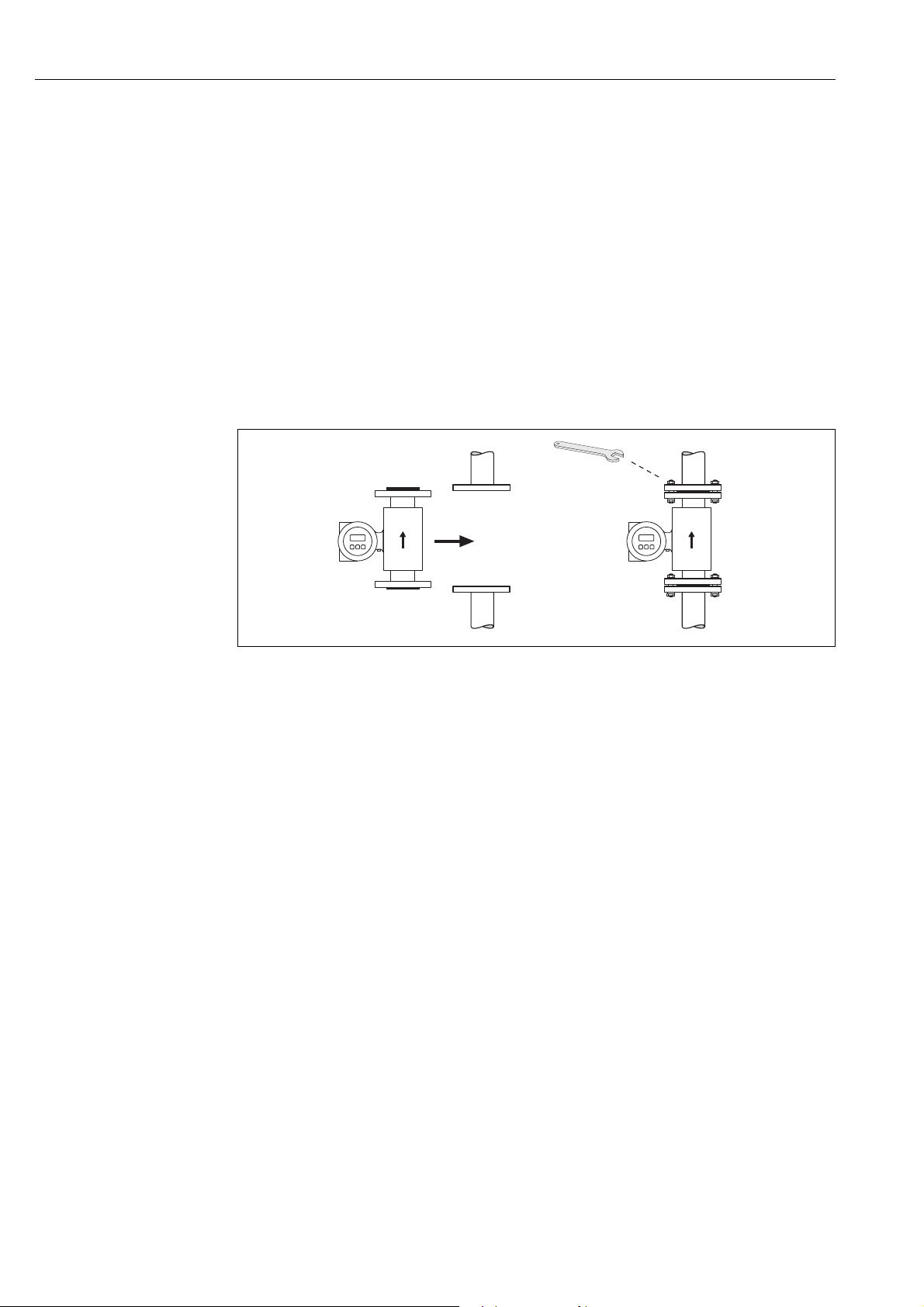
3.3.7 Installing the Promag W sensor
!
Note!
Bolts, nuts, seals, etc. are not included in the scope of supply and must be supplied by the
customer.
The sensor is designed for installation between the two piping flanges.
• Observe in any case the necessary screw tightening torques on 37
• If grounding disks are used, follow the mounting instructions which will be enclosed with
the shipment
a0004296
Fig. 26: Installing the Promag W sensor
Seals
Comply with the following instructions when installing seals:
• Hard rubber lining additional seals are always necessary.
•Polyurethane lining no seals are required.
• For DIN flanges, use only seals according to EN 1514-1.
• Make sure that the seals do not protrude into the piping cross-section.
Caution!
"
Risk of short circuit!
Do not use electrically conductive sealing compounds such as graphite! An electrically
conductive layer could form on the inside of the measuring tube and short-circuit the
measuring signal.
Ground cable
• If necessary, special ground cables for potential equalization can be ordered as an
accessory ( 74).
• Information on potential equalization and detailed mounting instructions for the use of
ground cables can be found on 54
36 Endress+Hauser
Page 37

Promag 10 Installation
Screw tightening torques (Promag W)
Please note the following:
• The tightening torques listed below are for lubricated threads only.
• Always tighten the screws uniformly and in diagonally opposite sequence.
• Overtightening the screws will deform the sealing faces or damage the seals.
• The tightening torques listed below apply only to pipes not subjected to tensile stress.
Tightening torques for:
•EN (DIN) 37
•JIS 40
•ASME 39
• AWWA 41
• AS 2129 41
• AS 4087 42
Promag W screw tightening torques for EN 1092-1 (DIN 2501), PN 6/10/16/25/40
Nominal
diameter
[mm] [mm] [Nm] [Nm]
25 PN 40 4 × M 12 18 - 15
32 PN 40 4 × M 16 18 - 24
40 PN 40 4 × M 16 18 - 31
50 PN 40 4 × M 16 20 48 40
65* PN 16 8 × M 16 18 32 27
65 PN 40 8 × M 16 22 32 27
80 PN 16 8 × M 16 20 40 34
80 PN 40 8 × M 16 24 40 34
100 PN 16 8 × M 16 20 43 36
100 PN 40 8 × M 20 24 59 50
125 PN 16 8 × M 16 22 56 48
125 PN 40 8 × M 24 26 83 71
150 PN 16 8 × M 20 22 74 63
150 PN 40 8 × M 24 28 104 88
200 PN 10 8 × M 20 24 106 91
200 PN 16 12 × M 20 24 70 61
200 PN 25 12 × M 24 30 104 92
250 PN 10 12 × M 20 26 82 71
250 PN 16 12 × M 24 26 98 85
250 PN 25 12 × M 27 32 150 134
300 PN 10 12 × M 20 26 94 81
300 PN 16 12 × M 24 28 134 118
300 PN 25 16 × M 27 34 153 138
350 PN 6 12 × M 20 22 111 120
350 PN 10 16 × M 20 26 112 118
350 PN 16 16 × M 24 30 152 165
350 PN 25 16 × M 30 38 227 252
400 PN 6 16 × M 20 22 90 98
400 PN 10 16 × M 24 26 151 167
400 PN 16 16 × M 27 32 193 215
400 PN 25 16 × M 33 40 289 326
450 PN 6 16 × M 20 22 112 126
450 PN 10 20 × M 24 28 153 133
450 PN 16 20 × M 27 40 198 196
450 PN 25 20 × M 33 46 256 253
500 PN 6 20 × M 20 24 119 123
500 PN 10 20 × M 24 28 155 171
500 PN 16 20 × M 30 34 275 300
EN (DIN)
pressure rating
Threaded
fasteners
Flange thick-
ness
Max. tightening torque
Hard rubber Polyurethane
Endress+Hauser 37
Page 38

Installation Promag 10
Nominal
diameter
[mm] [mm] [Nm] [Nm]
500 PN 25 20 × M 33 48 317 360
600 PN 6 20 × M 24 30 139 147
600 PN 10 20 × M 27 28 206 219
600 * PN 16 20 × M 33 36 415 443
600 PN 25 20 × M 36 58 431 516
700 PN 6 24 × M 24 24 148 139
700 PN 10 24 × M 27 30 246 246
700 PN 16 24 × M 33 36 278 318
700 PN 25 24 × M 39 46 449 507
800 PN 6 24 × M 27 24 206 182
800 PN 10 24 × M 30 32 331 316
800 PN 16 24 × M 36 38 369 385
800 PN 25 24 × M 45 50 664 721
900 PN 6 24 × M 27 26 230 637
900 PN 10 28 × M 30 34 316 307
900 PN 16 28 × M 36 40 353 398
900 PN 25 28 × M 45 54 690 716
1000 PN 6 28 × M 27 26 218 208
1000 PN 10 28 × M 33 34 402 405
1000 PN 16 28 × M 39 42 502 518
1000 PN 25 28 × M 52 58 970 971
1200 PN 6 32 × M 30 28 319 299
1200 PN 10 32 × M 36 38 564 568
1200 PN 16 32 × M 45 48 701 753
1400 PN 6 36 × M 33 32 430 398
1400 PN 10 36 × M 39 42 654 618
1400 PN 16 36 × M 45 52 729 762
1600 PN 6 40 × M 33 34 440 417
1600 PN 10 40 × M 45 46 946 893
1600 PN 16 40 × M 52 58 1007 1100
1800 PN 6 44 × M 36 36 547 521
1800 PN 10 44 × M 45 50 961 895
1800 PN 16 44 × M 52 62 1108 1003
2000 PN 6 48 × M 39 38 629 605
2000 PN 10 48 × M 45 54 1047 1092
2000 PN 16 48 × M 56 66 1324 1261
* Designed acc. to EN 1092-1 (not to DIN 2501)
EN (DIN)
pressure rating
Threaded
fasteners
Flange thick-
ness
Max. tightening torque
Hard rubber Polyurethane
Promag W screw tightening torques for EN 1092-1, PN 6/10/16/25, P245GH/stainlesssteel; Calculated according to EN 1591-1:2014 for flanges according to EN 1092-1:2013
Nominal
diameter
[mm] [mm] [Nm] [Nm]
350 PN 6 12 × M 20 22 60 75
350 PN 10 16 × M 20 26 70 80
350 PN 16 16 × M 24 30 125 135
350 PN 25 16 × M 30 38 230 235
400 PN 6 16 × M 20 22 65 70
400 PN 10 16 × M 24 26 100 120
400 PN 16 16 × M 27 32 175 190
400 PN 25 16 × M 33 40 315 325
450 PN 6 16 × M 20 22 70 90
450 PN 10 20 × M 24 28 100 110
EN (DIN)
Pressure rating
Threaded
fasteners
Flange thickness Nom. tightening torque
Hard rubber Polyurethane
38 Endress+Hauser
Page 39

Promag 10 Installation
Nominal
diameter
[mm] [mm] [Nm] [Nm]
450 PN 16 20 × M 27 34 175 190
450 PN 25 20 × M 33 46 300 310
500 PN 6 20 × M 20 24 65 70
500 PN 10 20 × M 24 28 110 120
500 PN 16 20 × M 30 36 225 235
500 PN 25 20 × M 33 48 370 370
600 PN 6 20 × M 24 30 105 105
600 PN 10 20 × M 27 30 165 160
600 PN 16 20 × M 33 40 340 340
600 PN 25 20 × M 36 48 540 540
700 PN 6 24 × M 24 30 110 110
700 PN 10 24 × M 27 35 190 190
700 PN 16 24 × M 33 40 340 340
700 PN 25 24 × M 39 50 615 595
800 PN 6 24 × M 27 30 145 145
800 PN 10 24 × M 30 38 260 260
800 PN 16 24 × M 36 41 465 455
800 PN 25 24 × M 45 53 885 880
900 PN 6 24 × M 27 34 170 180
900 PN 10 28 × M 30 38 265 275
900 PN 16 28 × M 36 48 475 475
900 PN 25 28 × M 45 57 930 915
1000 PN 6 28 × M 27 38 175 185
1000 PN 10 28 × M 33 44 350 360
1000 PN 16 28 × M 39 59 630 620
1000 PN 25 28 × M 52 63 1300 1290
1200 PN 6 32 × M 30 42 235 250
1200 PN 10 32 × M 36 55 470 480
1200 PN 16 32 × M 45 78 890 900
1400 PN 6 36 × M 33 56 300 1400 PN 10 36 × M 39 65 600 1400 PN 16 36 × M 45 84 1050 1600 PN 6 40 × M 33 63 340 1600 PN 10 40 × M 45 75 810 1600 PN 16 40 × M 52 102 1420 1800 PN 6 44 × M 36 69 430 1800 PN 10 44 × M 45 85 920 1800 PN 16 44 × M 52 110 1600 2000 PN 6 48 × M 39 74 530 2000 PN 10 48 × M 45 90 1040 2000 PN 16 48 × M 56 124 1900 -
EN (DIN)
Pressure rating
Threaded
fasteners
Flange thickness Nom. tightening torque
Hard rubber Polyurethane
Promag W screw tightening torques for ASME B16.5, Class 150/300
Nominal
diameter
[mm] [inch] [Nm] [lbf · ft] [Nm] [lbf · ft]
25 1" Class 150 4 × ½" - - 7 5
25 1" Class 300 4 × 5/8" - - 8 6
40 1 ½" Class 150 4 × ½" - - 10 7
40 1 ½" Class 300 4 × ¾" - - 15 11
50 2" Class 150 4 × 5/8" 35 26 22 16
50 2" Class 300 8 × 5/8" 18 13 11 8
80 3" Class 150 4 × 5/8" 60 44 43 32
ASME Threaded Max. tightening torque
fasteners
Pressure rating
Hard rubber Polyurethane
Endress+Hauser 39
Page 40

Installation Promag 10
Nominal
diameter
[mm] [inch] [Nm] [lbf · ft] [Nm] [lbf · ft]
80 3" Class 300 8 × ¾" 38 28 26 19
100 4" Class 150 8 × 5/8" 42 31 31 23
100 4" Class 300 8 × ¾" 58 43 40 30
150 6" Class 150 8 × ¾" 79 58 59 44
150 6" Class 300 12 × ¾" 70 52 51 38
200 8" Class 150 8 × ¾" 107 79 80 59
250 10" Class 150 12 × 7/8" 101 74 75 55
300 12" Class 150 12 × 7/8" 133 98 103 76
350 14" Class 150 12 × 1" 135 100 158 117
400 16" Class 150 16 × 1" 128 94 150 111
450 18" Class 150 16 × 1 ¹⁄" 204 150 234 173
500 20" Class 150 20 × 1 ¹⁄" 183 135 217 160
600 24" Class 150 20 × 1 ¼" 268 198 307 226
ASME Threaded Max. tightening torque
fasteners
Pressure rating
Hard rubber Polyurethane
Promag W screw tightening torques for JIS B2220, 10/20K
Nominal diameter JIS Threaded
Pressure rating Hard rubber Polyurethane
[mm] [Nm] [Nm]
25 10K 4 × M 16 - 19
25 20K 4 × M 16 - 19
32 10K 4 × M 16 - 22
32 20K 4 × M 16 - 22
40 10K 4 × M 16 - 24
40 20K 4 × M 16 - 24
50 10K 4 × M 16 40 33
50 20K 8 × M 16 20 17
65 10K 4 × M 16 55 45
65 20K 8 × M 16 28 23
80 10K 8 × M 16 29 23
80 20K 8 × M 20 42 35
100 10K 8 × M 16 35 29
100 20K 8 × M 20 56 48
125 10K 8 × M 20 60 51
125 20K 8 × M 22 91 79
150 10K 8 × M 20 75 63
150 20K 12 × M 22 81 72
200 10K 12 × M 20 61 52
200 20K 12 × M 22 91 80
250 10K 12 × M 22 100 87
250 20K 12 × M 24 159 144
300 10K 16 × M 22 74 63
300 20K 16 × M 24 138 124
fasteners
Max. tightening torque
Promag W screw tightening torques for JIS B2220, 10/20K
Nominal
diameter
[mm] [Nm] [Nm]
350 10K 16 × M 22 109 109
350 20K 16 × M 30x3 217 217
400 10K 16 × M 24 163 163
400 20K 16 × M 30x3 258 258
450 10K 16 × M 24 155 155
450 20K 16 × M 30x3 272 272
JIS Pressure
rating
Threaded fas-
teners
Nom. tightening torque
Hard rubber Polyurethane
40 Endress+Hauser
Page 41

Promag 10 Installation
Nominal
diameter
[mm] [Nm] [Nm]
500 10K 16 × M 24 183 183
500 20K 16 × M 30x3 315 315
600 10K 16 × M 30 235 235
600 20K 16 × M 36x3 381 381
700 10K 16 × M 30 300 300
750 10K 16 × M 30 339 339
JIS Pressure
rating
Threaded fas-
teners
Nom. tightening torque
Hard rubber Polyurethane
Promag W screw tightening torques for AWWA C2074, Class D
Nominal diameter AWWA Threaded Max. tightening torque
Pressure
[mm] [inch] [Nm] [lbf · ft] [Nm] [lbf · ft]
700 28" Class D 28 × 1 ¼" 247 182 292 215
750 30" Class D 28 × 1 ¼" 287 212 302 223
800 32" Class D 28 × 1 ½" 394 291 422 311
900 36" Class D 32 × 1 ½" 419 309 430 317
1000 40" Class D 36 × 1 ½" 420 310 477 352
- 42" Class D 36 × 1 ½" 528 389 518 382
1200 48" Class D 44 × 1 ½" 552 407 531 392
- 54" Class D 44 × 1 ¾" 730 538 633 467
- 60" Class D 52 × 1 ¾" 758 559 832 614
- 66" Class D 52 × 1 ¾" 946 698 955 704
1800 72" Class D 60 × 1 ¾" 975 719 1087 802
- 78" Class D 64 × 2" 853 629 786 580
2000 - Class D 64 × 2" 853 629 786 580
rating
fasteners
Hard rubber Polyurethane
Promag W screw tightening torques for AS 2129, Table E
Nominal diameter
[mm]
50 Table E 4 × M 16 32
80 Table E 4 × M 16 49
100 Table E 8 × M 16 38
150 Table E 8 × M 20 64
200 Table E 8 × M 20 96
250 Table E 12 × M 20 98
300 Table E 12 × M 24 123
350 Table E 12 × M 24 203
400 Table E 12 × M 24 226
450 Table E 16 × M 24 226
500 Table E 16 × M 24 271
600 Table E 16 × M 30 439
700 Table E 20 × M 30 355
750 Table E 20 × M 30 559
800 Table E 20 × M 30 631
900 Table E 24 × M 30 627
1000 Table E 24 × M 30 634
1200 Table E 32 × M 30 727
AS 2129
Pressure rating
Threaded
fasteners
Max. tightening torque
Hard rubber
[Nm]
Endress+Hauser 41
Page 42

Installation Promag 10
Promag W screw tightening torques for AS 4087, PN16
Nominal diameter
[mm]
50 Table E 4 × M 16 32
80 PN 16 4 × M 16 49
100 PN 16 4 × M 16 76
150 PN 16 8 × M 20 52
200 PN 16 8 × M 20 77
250 PN 16 8 × M 20 147
300 PN 16 12 × M 24 103
350 PN 16 12 × M 24 203
375 PN 16 12 × M 24 137
400 PN 16 12 × M 24 226
450 PN 16 12 × M 24 301
500 PN 16 16 × M 24 271
600 PN 16 16 × M 27 393
700 PN 16 20 × M 27 330
750 PN 16 20 × M 30 529
800 PN 16 20 × M 33 631
900 PN 16 24 × M 33 627
1000 PN 16 24 × M 33 595
1200 PN 16 32 × M 33 703
AS 4087
Pressure rating
Threaded
fasteners
Max. tightening torque
Hard rubber
[Nm]
42 Endress+Hauser
Page 43

Promag 10 Installation
Esc
E
-
+
Esc
E
-
+
3
5
6
1
2
4
4 x 45°
3.3.8 Turning the transmitter housing
1. Loosen the two securing screws.
2. Turn the bayonet lock as far as it will go.
3. Carefully lift the transmitter housing:
– Promag D: approx. 10 mm (0.39 in) above the securing screws
– Promag E/H/L/P/W: to the stop
4. Turn the transmitter housing to the desired position:
– Promag D: max. 180° clockwise or max. 180° counterclockwise
– Promag E/H/L/P/W: max. 280° clockwise or max. 20° counterclockwise
5. Lower the housing into position and re-engage the bayonet catch.
6. Retighten the two securing screws.
Fig. 27: Turning the transmitter housing
3.3.9 Turning the onsite display
1. Unscrew cover of the electronics compartment from the transmitter housing.
2. Remove the display module from the transmitter retaining rails.
3. Turn the display to the desired position (max. 4 × 45° in each direction).
4. Fit the display back onto the retaining rails.
5. Screw the cover of the electronics compartment firmly back onto the transmitter
housing.
a0005393
Fig. 28: Turning the local display
Endress+Hauser 43
A0003237
Page 44

Installation Promag 10
248 ±2
(9.76 ±0.08)
238 (9.37)
AB
ANSCHLUSSKLEMMEN - FIELD TERMINALS
3.3.10 Mounting the transmitter (remote version)
The transmitter can be mounted in the following ways:
•Wall mounting
• Pipe mounting (with separate mounting kit, accessories 74)
The transmitter and the sensor must be mounted separate in the following circumstances:
• Poor accessibility
• Lack of space
• Extreme fluid/ambient temperatures (temperature ranges 92)
• Severe vibration (> 2 g/2 h per day; 10 to 100 Hz)
Caution!
"
• The ambient temperature range -20 to +60 °C (–4 to +140 °F) may not be exceeded at the
mounting location. Avoid direct sunlight.
• If the device is mounted to a warm pipe, make sure that the housing temperature does not
exceed +60 °C (+140 °F), which is the maximum permissible temperature.
Mount the transmitter as illustrated in 29.
Fig. 29: Mounting the transmitter (remote version). Engineering unit mm (in)
A Direct wall mounting
BPipe mounting
A0010719
44 Endress+Hauser
Page 45

Promag 10 Installation
3.4 Post-installation check
Perform the following checks after installing the measuring device in the pipe:
Device condition and specifications Notes
Is the device damaged (visual inspection)? –
Does the device correspond to specifications at the measuring point,
including process temperature and pressure, ambient temperature, minimum
fluid conductivity, measuring range, etc.?
Installation Notes
Does the arrow on the sensor nameplate match the actual direction of flow
through the pipe?
Is the position of the measuring electrode plane correct? 13
Is the position of the empty pipe detection electrode correct? 13
Were all screws tightened to the specified torques when the sensor was
installed?
Were the correct seals used (type, material, installation)? Promag D 18
Are the measuring point number and labeling correct (visual inspection)? –
Process environment / process conditions Notes
Were the inlet and outlet runs respected? Inlet run 5 × DN
Is the measuring device protected against moisture and direct sunlight? –
Is the sensor adequately protected against vibration (attachment, support)? Acceleration up to 2 g by
93
–
Promag D 20
Promag E 23
Promag L 28
Promag P 32
Promag W 37
Promag E 22
Promag H 25
Promag L 27
Promag P 32
Promag W 36
Outlet run 2 × DN
analogy with IEC 600 68-2-8
Endress+Hauser 45
Page 46

Wiring Promag 10
4 Wiring
#
!
#
"
Warning!
When using remote versions, only sensors and transmitters with the same serial number can
be connected up. Measuring errors can occur if the devices are not connected in this way.
Note!
The device does not have an internal circuit breaker. For this reason, assign the device a
switch or power-breaker switch capable of disconnecting the power supply line from the
mains.
4.1 Connecting the remote version
4.1.1 Connecting Promag D/E/H/L/P/W
Warning!
• Risk of electric shock! Switch off the power supply before opening the device. Do not install
or wire the device while it is connected to the power supply. Failure to comply with this
precaution can result in irreparable damage to the electronics.
• Risk of electric shock! Connect the protective conductor to the ground terminal on the
housing before the power supply is applied.
Caution!
• Only sensors and transmitters with the same serial number can be connected to one
another. Communication problems can occur if the devices are not connected in this way.
• Risk of damaging the coil driver. Always switch off the power supply before connecting or
disconnecting the coil current cable.
Procedure
1. Transmitter: Loosen the securing clamp and remove the cover from the connection
compartment (a).
2. Sensor: Remove the cover from the connection housing (b).
3. Feed the electrode cable (c) and the coil current cable (d) through the appropriate cable
entries.
Caution!
"
Route the connecting cables securely (see "Length of connecting cable" 16).
4. Terminate the signal and coil current cable as indicated in the table:
Promag D/E/L/P/W Refer to the table 49
Promag H Refer to the "Cable termination" table 50
5. Establish the wiring between the sensor and the transmitter.
The electrical wiring diagram that applies to your device can be found:
– In the corresponding graphic:
30 (Promag D); 31 (Promag E/L/P/W); 32 (Promag H)
– In the cover of the sensor and transmitter
Note!
!
The cable shields of the Promag H sensor are grounded by means of the strain relief
terminals (see also the "Cable termination" table 50)
Caution!
"
Insulate the shields of cables that are not connected to eliminate the risk of shortcircuits with neighboring cable shields inside the connection housing.
6. Transmitter: Secure the cover to the connection compartment (a) and tighten the socket
head cap screw of the securing clamp.
7. Sensor: Secure the cover on the connection housing (b).
46 Endress+Hauser
Page 47

Promag 10 Wiring
b
S1
E1
E2
S2
GND
E
S
42 41
6
5
7
8
4
37 36
dc
a
d
c
E1
E2
E
5
7
4
37
42 41
n.c. n.c.
b
n.c.
S1
E1
E2
S2
GND
E
S
42 41
6
5
7
8
4
37 36
dc
a
d
c
E1
E2
E
5
7
4
37
42 41
n.c. n.c.
Promag D
a0010695
Fig. 30: Connecting the remote version of Promag D
a Wall-mount housing connection compartment
b Cover of the sensor connection housing
c Electrode cable
d Coil current cable
n.c. Not connected, insulated cable shields
Wire colors/Terminal No.:
5/6 = braun, 7/8 = white, 4 = green, 37/36 = yellow
Promag E/L/P/W
A0012461
Fig. 31: Connecting the remote version of Promag E/L/P/W
a Wall-mount housing connection compartment
b Cover of the sensor connection housing
c Electrode cable
d Coil current cable
n.c. Not connected, insulated cable shields
Wire colors/Terminal No.:
5/6 = braun, 7/8 = white, 4 = green, 37/36 = yellow
Endress+Hauser 47
Page 48

Wiring Promag 10
E1
E2
GND
E
S1
E1
E2
S2
GND
E
S
5
7
4
37
42 41
42 41
6
5
7
8
4
37 36
n.c. n.c.
dc
n.c.
b
a
d
c
Promag H
Fig. 32: Connecting the remote version of Promag H
a Wall-mount housing connection compartment
b Cover of the sensor connection housing
c Electrode cable
d Coil current cable
n.c. Not connected, insulated cable shields
Wire colors/Terminal No.:
5/6 = braun, 7/8 = white, 4 = green, 37/36 = yellow
A0012477
48 Endress+Hauser
Page 49

Promag 10 Wiring
A B
80 (3.15)
50 (2.0)
17 (0.67)
8 (0.32)
Esc
E
-
+
GND
m
n
m
m
m
n
n
n
mm (inch)
B
A
70 (2.76)
50 (2.0)
10 (0.4)
8 (0.32)
E
-
+
m
m
m
mm (inch)
80 (3.15)
50 (2.0)
17 (0.67)
8 (0.32)
³1 (0.04)
A
B
m
n
m
n
n
GND
mm (inch)
B
A
70 (2.76)
50 (2.0)
10 (0.4)
8 (0.32)
m
m
m
mm (inch)
Cable termination for the remote version
Promag D/E/L/P/W
Terminate the signal and coil current cables as shown in the figure below (Detail A).
Ferrules must be provided on the fine-wire cores (Detail B: 1 = red ferrules, 1.0 mm; 2 = white ferrules, 0.5 mm).
Caution!
"
When fitting the connectors, pay attention to the following points:
• Electrode cable Make sure that the ferrules do not touch the wire shield on the sensor side.
Minimum distance = 1 mm (exception "GND" = green cable)
• Coil current cable Insulate one core of the three-core wire at the level of the core reinforcement; you only require two cores for the connection.
TRANSMITTER
Electrode cable Coil current cable
a0005391
Engineering unit mm (in)
SENSOR
Electrode cable Coil current cable
Engineering unit mm (in)
Engineering unit mm (in)
Endress+Hauser 49
A0003241
Engineering unit mm (in)
a0005390
A0003240
Page 50

Wiring Promag 10
A B
80 (3.15)
50 (2.0)
17 (0.67)
8 (0.32)
Esc
E
-
+
GND
m
n
m
m
m
n
n
n
mm (inch)
B
A
70 (2.76)
50 (2.0)
10 (0.4)
8 (0.32)
E
-
+
m
m
m
mm (inch)
A
B
GND
m
n
n
n
80 (3.15)
15 (0.59)
8 (0.31)
17 (0.67)
³
1 (0.04)
A
B
m
m
70 (2.76)
8 (0.31)
40(1.57)
Cable termination for the remote version
Promag H
Terminate the signal and coil current cables as shown in the figure below (Detail A).
Ferrules must be provided on the fine-wire cores (Detail B: 1 = red ferrules, 1.0 mm; 2 = white ferrules, 0.5 mm).
Caution!
"
When fitting the connectors, pay attention to the following points:
• Electrode cable Make sure that the ferrules do not touch the wire shield on the sensor side.
Minimum distance = 1 mm (exception "GND" = green cable).
• Coil current cable Insulate one core of the three-core wire at the level of the core reinforcement; you only require two cores for the connection.
• On the sensor side, reverse both cable shields approx. 15 mm over the outer jacket. The strain relief ensures an electrical connection with the
connection housing.
TRANSMITTER
Electrode cable Coil current cable
a0005391
Engineering unit mm (in)
Engineering unit mm (in)
SENSOR
Electrode cable Coil current cable
A0002647
Engineering unit mm (in)
Engineering unit mm (in)
50 Endress+Hauser
a0005390
A0002648
Page 51

Promag 10 Wiring
1
2
3
4
5
6
7
a
b
4.1.2 Cable specifications
Electrode cable
• 3 × 0.38 mm² PVC cable with common, braided copper shield ( ~ 9.5 mm / 0.37") and
individually shielded cores
• With Empty Pipe Detection (EPD): 4 × 0.38 mm² PVC cable with common, braided copper
shield ( ~ 9.5 mm / 0.37") and individually shielded cores
• Conductor resistance: 50 /km
• Capacitance: core/shield: 420 pF/m
• Permanent operating temperature: –20 to +80 °C
• Cable cross-section: max. 2.5 mm²
Coil current cable
• 3 × 0.75 mm² PVC cable with common, braided copper shield ( ~9 mm / 0.35")
• Conductor resistance: 37 /km
• Capacitance: core/core, shield grounded: 120 pF/m
• Operating temperature: –20 to +80 °C
• Cable cross-section: max. 2.5 mm²
• Test voltage for cable insulation: 1433 V AC r.m.s. 50/60 Hz or 2026 V DC
Fig. 33: Cable cross-section
a Electrode cable
b Coil current cable
1Core
2 Core insulation
3 Core shield
4 Core jacket
5 Core reinforcement
6 Cable shield
7 Outer jacket
Operation in zones of severe electrical interference:
The measuring device complies with the general safety requirements in accordance with EN
61010 and the EMC requirements of IEC/EN 61326.
Caution!
"
Grounding is by means of the ground terminals provided for the purpose inside the
connection housing. Ensure that the stripped and twisted lengths of cable shield to the
ground terminal are as short as possible.
A0003194
Endress+Hauser 51
Page 52

Wiring Promag 10
b
a
e
e
b
2127
–
25–26
+
24
+
L1
(L+)
N
(L-)
e
g
b
d
h
i
c
f
4.2 Connecting the measuring unit
4.2.1 Transmitter
#
Warning!
• Risk of electric shock!
Switch off the power supply before opening the device. Do not install or wire the device
while it is connected to the power supply. Failure to comply with this precaution can result
in irreparable damage to the electronics.
• Risk of electric shock!
Connect the protective conductor to the ground terminal on the housing before the power
supply is applied.
• Compare the specifications on the nameplate with the local supply voltage and frequency.
The national regulations governing the installation of electrical equipment also apply.
• The transmitter must be included in the building fuse system.
1. Unscrew cover of the electronics compartment from the transmitter housing.
2. Press the side latches and flip down the cover of the connection compartment.
3. Feed the cable for the power supply and the electrode cable through the appropriate
cable entries.
4. Remove the terminal connectors from the transmitter housing and connect the cable for
the power supply and the electrode cable:
– Wiring diagram 34
– Electrical connection 53
5. Plug the terminal connectors back into the transmitter housing.
Note!
!
The connectors are coded so you cannot mix them up.
6. Secure the ground cable to the ground terminal.
7. Flip up the cover of the connection compartment.
8. Screw the cover of the electronics compartment firmly onto the transmitter housing.
A0003192
Fig. 34: Connecting the transmitter (aluminum field housing).
a Electronics compartment cover
b Cable for power supply: 85 to 250 V AC, 11 to 40 V DC, 20 to 28 V AC
c Ground terminal for power supply cable
d Terminal connector for power supply: No. 1–2 → 53 (electrical connection)
e Electrode cable
f Ground terminal for electrode cable
g Terminal connector for electrode cable: No. 24–27 → 53 (electrical connection)
h Service connector
i Ground terminal for potential equalization
Cable cross-section: max. 2.5 mm²
52 Endress+Hauser
Page 53

Promag 10 Wiring
+26
³ 250 Ω
–27
1
3
4
2
+26
³ 250 Ω
–27
RS 232
1
3
4
2
4.2.2 Terminal assignment
!
Order characteristic for
"inputs/outputs"
A Pulse output Current output HART Power supply
Terminal No. (outputs/power supply)
24 (+) / 25 (–) 26 (+) / 27 (–) 1 (L1/L+) / 2 (N/L–)
Note!
Functional values of the outputs and power supply 90
4.2.3 HART connection
Users have the following connection options at their disposal:
• Direct connection to transmitter by means of terminals 26(+) and 27 (-)
• Connection by means of the 4 to 20 mA circuit.
• The measuring loop's minimum load must be at least 250 .
• After commissioning, make the following settings:
– CURRENT SPAN function "4–20 mA HART"
– Switch HART write protection on or off 64
Connection of the HART handheld communicator
See also the documentation issued by the HART Communication Foundation, and in
particular HCF LIT 20: "HART, a technical summary".
Fig. 35: Electrical connection of HART handheld Field Xpert SFX100
1 HART handheld Field Xpert SFX100
2 Auxiliary energy
3Shielding
4 Other devices or PLC with passive input
Connection of a PC with an operating software
In order to connect a PC with an operating software (e.g. "FieldCare), a HART modem
(e.g. Commubox FXA 195) is needed.
Fig. 36: Electrical connection of a PC with an operating software
1 PC with an operating software
2 Other evaluation devices or PLC with passive input
3Shield
4 HART modem, e.g. Commubox FXA 195
a0005573
a0005574
Endress+Hauser 53
Page 54

Wiring Promag 10
4.3 Potential equalization
#
"
Warning!
The measuring system must be included in the potential equalization.
Perfect measurement is only ensured when the fluid and the sensor have the same electrical
potential. This is ensured by the reference electrode integrated in the sensor as standard.
The following should also be taken into consideration for potential equalization:
• Internal grounding concepts in the company
• Operating conditions, such as the material/grounding of the pipes (see Table)
4.3.1 Potential equalization for Promag D
• No reference electrode is integrated!
For the two ground disks of the sensor an electrical connection to the fluid is always
ensured.
• Exampels for connections 54
4.3.2 Potential equalization for Promag E/L/P/W
• Reference electrode integrated in the sensor as standard
• Exampels for connections 55
4.3.3 Potential equalization for Promag H
No reference electrode is integrated!
For the metal process connections of the sensor a electrical connection to the fluid is always
ensured.
Caution!
If using process connections made of a synthetic material, ground rings have to be used to
ensure that potential is equalized ( 25). The necessary ground rings can be ordered
separately from Endress+Hauser as accessories ( 74).
4.3.4 Exampels for potential equalization connections for Promag D
Standard case
Operating conditions Potential equalization
When using the measuring device in a:
• Metal, grounded pipe
• Plastic pipe
• Pipe with insulating lining
Potential equalization takes place via the ground terminal
of the transmitter (standard situation).
Note!
!
When installing in metal pipes, we recommend you connect
the ground terminal of the transmitter housing with the
piping.
Fig. 37: Via the ground terminal of the transmitter
a0010702
54 Endress+Hauser
Page 55

Promag 10 Wiring
1
2
2
Special cases for Promag D as wafer version
Operating conditions Potential equalization
When using the measuring device in a:
• Metal pipe that is not grounded
This connection method also applies in situations where:
• Customary potential equalization cannot be ensured
• Excessively high equalizing currents can be expected
Potential equalization takes place via the ground terminal
of the transmitter and the two pipe flanges.
Here, the ground cable (copper wire, 6 mm² / 0.0093 in²) is
mounted directly on the conductive flange coating with
flange screws.
a0010703
When using the measuring device in a:
• Pipe with a cathodic protection unit
The device is installed potential-free in the pipe.
Only the two flanges of the pipe are connected with a
ground cable (copper wire, 6 mm² / 0.0093 in²). Here, the
ground cable is mounted directly on the conductive flange
coating with flange screws.
Note the following when installing:
• The applicable regulations regarding potential-free
installation must be observed.
•There should be no electrically conductive connection
between the pipe and the device.
• The mounting material must withstand the applicable
torques.
Fig. 38: Via the ground terminal of the transmitter
Fig. 39: Potential equalization and cathodic
1 Power supply isolation transformer
2 Electrically isolated
and the flanges of the pipe
a0010704
protection
4.3.5 Exampels for potential equalization connections for Promag E/L/P/W
Standard case
Operating conditions Potential equalization
When using the measuring device in a:
• Metal, grounded pipe
Potential equalization takes place via the ground terminal
of the transmitter (standard situation).
Note!
!
When installing in metal pipes, we recommend you connect
the ground terminal of the transmitter housing with the
piping.
Fig. 40: Via the ground terminal of the transmitter
a0010702
Endress+Hauser 55
Page 56

Wiring Promag 10
DN 300£
DN 350
³
1
2 2
Special cases
Operating conditions Potential equalization
When using the measuring device in a:
• Metal pipe that is not grounded
This connection method also applies in situations where:
• Customary potential equalization cannot be ensured
• Excessively high equalizing currents can be expected
Both sensor flanges are connected to the pipe flange by
means of a ground cable (copper wire, 6 mm² / 0.0093 in²)
and grounded. Connect the transmitter or sensor
connection housing, as applicable, to ground potential by
means of the ground terminal provided for the purpose.
Ground cable installation depends on the nominal
diameter:
•DN 300: The ground cable is mounted directly on the
conductive flange coating with the flange screws.
•DN 350: The ground cable is mounted directly on the
metal transport bracket.
Note!
!
The ground cable for flange-to-flange connections can be
ordered separately as an accessory from Endress+Hauser.
Fig. 41: Via the ground terminal of the transmitter
and the flanges of the pipe
a0010703
When using the measuring device in a:
• Plastic pipe
• Pipe with insulating lining
This connection method also applies in situations where:
• Customary potential equalization cannot be ensured
• Excessively high equalizing currents can be expected
Potential equalization takes place using additional ground
disks, which are connected to the ground terminal via a
ground cable (copper wire, min. 6 mm² / 0.0093 in²). When
installing the ground disks, please comply with the enclosed
Installation Instructions.
When using the measuring device in a:
• Pipe with a cathodic protection unit
The device is installed potential-free in the pipe.
Only the two flanges of the pipe are connected with a
ground cable (copper wire, 6 mm² / 0.0093 in²). Here, the
ground cable is mounted directly on the conductive flange
coating with flange screws.
Note the following when installing:
• The applicable regulations regarding potential-free
installation must be observed.
•There should be no electrically conductive connection
between the pipe and the device.
• The mounting material must withstand the applicable
torques.
a0010702
Fig. 42: Via the ground terminal of the transmitter
a0010704
Fig. 43: Potential equalization and cathodic
1 Power supply isolation transformer
2 Electrically isolated
protection
56 Endress+Hauser
Page 57

Promag 10 Wiring
ab
4.4 Degree of protection
The devices meet all the requirements of IP 67 degree of protection.
Compliance with the following points is mandatory following installation in the field or
servicing in order to ensure that IP 67 protection is maintained:
• The housing seals must be clean and undamaged when inserted into their grooves. The
seals must be dried, cleaned or replaced if necessary.
• All threaded fasteners and screw covers must be firmly tightened.
• The cables used for connection must be of the specified outside diameter 51.
• Firmly tighten the cable entries.
• The cables must loop down before they enter the cable entries ("water trap"). This
arrangement prevents moisture penetrating the entry. Always install the measuring
device in such a way that the cable entries do not point up.
• Remove all unused cable entries and insert plugs instead.
• Do not remove the grommet from the cable entry.
"
!
a0001914
Fig. 44: Installation instructions, cable entries
Caution!
Do not loosen the threaded fasteners of the sensor housing, as otherwise the degree of
protection guaranteed by Endress+Hauser no longer applies.
Note!
• The Promag E/L/P/W sensors can be supplied with IP 68 rating (permanent immersion in
water to a depth of 3 meters (10 ft)). In this case the transmitter must be installed remote
from the sensor.
• The Promag L sensors with IP 68 rating are only available with stainless steel flanges.
• The remote version in IP67, type 6 of Promag L sensors is available for temporary use in
water.
Endress+Hauser 57
Page 58

Wiring Promag 10
4.5 Post-connection check
Perform the following checks after completing electrical installation of the measuring
device:
Device condition and specifications Notes
Are cables or the device damaged (visual inspection)? –
Electrical connection Notes
Does the supply voltage match the specifications on the nameplate? • 85 to 250 V AC (50 to 60 Hz)
• 20 to 28 V AC (50 to 60 Hz),
11 to 40 V DC
Do the cables used comply with the necessary specifications? 51
Do the cables have adequate strain relief? –
Is the cable type route completely isolated?
Without loops and crossovers?
Are the power-supply and electrode cables correctly connected? See the wiring diagram inside
Only remote version:
Is the flow sensor connected to the matching transmitter electronics?
Only remote version:
Is the connecting cable between sensor and transmitter connected correctly?
Are all screw terminals firmly tightened? –
Have the measures for grounding/potential equalization been correctly
implemented?
Are all cable entries installed, firmly tightened and correctly sealed?
Cables looped as "water traps"?
Are all housing covers installed and firmly tightened? –
–
the cover of the terminal
compartment
Check serial number on
nameplates of sensor and
connected transmitter.
46
54
57
58 Endress+Hauser
Page 59

Promag 10 Operation
Esc
E
+
-
1
32
+48.25 xx/yy
+3702.6 x
5Operation
5.1 Display and operating elements
The local display enables you to read all important parameters directly at the measuring
point and configure the device.
The display area consists of two lines; this is where measured values are displayed, and/or
status variables (partially filled pipe, etc.). The assignment of the display lines in operating
mode is specified. The top line displays the volume flow and the bottom line displays the
totalizer status.
A0001141
Fig. 45: Display and operating elements
1 Liquid crystal display
The two-line liquid-crystal display shows measured values, dialog texts, error messages and information messages. The
display as it appears when normal measuring is in progress is known as the HOME position (operating mode).
– Upper display line: Shows primary measured values, e.g. volume flow [e.g. in ml/min]
– Lower display line: Shows the totalizer status, [e.g. in m
2 Plus/minus keys
– Enter numerical values, select parameters
– Select different function groups within the function matrix
Press the +/- keys simultaneously to trigger the following functions:
– Exit the function matrix step by step → HOME position
– Press and hold down +/- keys for longer than 3 seconds → Return directly to HOME position
– Cancel data entry
3Enter key
–HOME position→ Entry into the function matrix
– Save the numerical values you input or settings you change
3
]
Endress+Hauser 59
Page 60

Operation Promag 10
>3s
-
+
E
Esc
E
E
E
E
E E E E E
–
+
+
Esc
–
+
Esc
–
+
Esc
–
E
m
n
o
p
5.2 Brief operating instructions on the function matrix
!
Note!
• See the general notes on 61.
• Function matrix overview 116
• Detailed description of all functions 117 ff.
The function matrix comprises two levels, namely the function groups and the functions of
the function groups.
The groups are the highest-level grouping of the control options for the device. A number of
functions is assigned to each group. You select a group in order to access the individual
functions for operating and configuring the device.
1. HOME position Enter the function matrix
2. Select a function group (e.g. OPERATION)
3. Select a function (e.g. LANGUAGE)
Change parameter/enter numerical values:
P select or enter enable code, parameters, numerical values
save your entries
4. Exit the function matrix:
– Press and hold down Esc key (
– Repeatedly press Esc key (
X) for longer than 3 seconds HOME position
X) return step by step to HOME position
Fig. 46: Selecting functions and configuring parameters (function matrix)
60 Endress+Hauser
A0001142
Page 61

Promag 10 Operation
5.2.1 General notes
The brief commissioning guide ( 70) is adequate for commissioning in most instances.
Complex measuring operations on the other hand necessitate additional functions that you
can configure as necessary and customize to suit your process parameters. The function
matrix, therefore, comprises a multiplicity of additional functions which, for the sake of
clarity, are arranged in a number of function groups.
Comply with the following instructions when configuring functions:
• You select functions as described on 60.
• You can switch off certain functions (OFF). If you do so, related functions in other function
groups will no longer be displayed.
• Certain functions prompt you to confirm your data entries.
Press P to select "SURE [ YES ]" and press again to confirm. This saves your setting or
starts a function, as applicable.
• Return to the HOME position is automatic if no key is pressed for 5 minutes.
!
"
Note!
• The transmitter continues to measure while data entry is in progress, i.e. the current
measured values are output via the signal outputs in the normal way.
• If the power supply fails, all preset and configured values remain safely stored in the
EEPROM.
5.2.2 Enabling the programming mode
The function matrix can be disabled. Disabling the function matrix rules out the possibility
of inadvertent changes to device functions, numerical values or factory settings. A numerical
code (factory setting = 10) has to be entered before settings can be changed.
If you use a code of your choice, you exclude the possibility of unauthorized persons
accessing data, see ACCESS CODE function 119.
Comply with the following instructions when entering codes:
• If programming is disabled and the
prompt for the code automatically appears on the display.
• If "0" is specified as the customer's code, programming is always enabled.
• The Endress+Hauser service organization can be of assistance if you mislay your personal
code.
Caution!
Changing certain parameters such as all sensor characteristics, for example, influences
numerous functions of the entire measuring system, particularly measuring accuracy.
Normally, such parameters may not be changed! Please contact Endress+Hauser if you have
any questions.
P operating elements are pressed in any function, a
5.2.3 Disabling the programming mode
Programming is disabled if you do not press the operating elements within 60 seconds
following automatic return to the HOME position.
You can also disable programming in the "ACCESS CODE" function by entering any number
(other than the customer's code).
Endress+Hauser 61
Page 62

Operation Promag 10
1
2453
XXXXXXXXXX
#000 00:00:05
P
5.3 Displaying error messages
5.3.1 Type of error
Errors which occur during commissioning or measuring operation are displayed
immediately. If two or more system or process errors occur, the error with the highest
priority is the one shown on the display.
The measuring system distinguishes between two types of error:
• System errors → 78:
This group comprises all device errors, e.g. communication errors, hardware faults, etc.
• Process errors 79:
This group comprises all application errors, e.g. empty pipe, etc.
!
Fig. 47: Error messages on the display (example)
1 Error type:
– P = process error
– S = system error
2 Error message type:
$
= fault message
–
– ! = notice message
3 Error designation: e.g. EMPTY PIPE = measuring tube is only partly filled or completely empty
4 Error number: e.g. #401
5 Duration of most recent error occurrence (in hours, minutes and seconds)
5.3.2 Error message types
Notice message (!)
• Displayed as Exclamation mark (!), error type (S: system error, P: process error)
• The error in question has no effect on the outputs of the measuring device.
Fault message (
• Displayed as Lightning flash (
• The error in question has a direct effect on the outputs.
The response of the individual outputs (failsafe mode) can be defined in the function
matrix using the "FAILSAFE MODE" function 137.
Note!
For security reasons, error messages should be output via the status output.
$)
$), error type (S: system error, P: process error).
A0000991
62 Endress+Hauser
Page 63

Promag 10 Operation
5.4 Communication
In addition to local operation, the measuring device can be configured and measured values
can be obtained by means of the HART protocol. Digital communication takes place using the
4–20 mA current output HART 53.
The HART protocol allows the transfer of measuring and device data between the HART
master and the field devices for configuration and diagnostics purposes.
The HART master, e.g. a handheld terminal or PC-based operating programs (such as
FieldCare), require device description (DD) files which are used to access all the information
in a HART device. Information is exclusively transferred using so-called "commands". There
are three different command classes:
• Universal commands:
All HART device support and use universal commands.
The following functionalities are linked to them:
– Identify HART devices
– Reading digital measured values (volume flow, totalizer, etc.)
• Common practice commands:
Common practice commands offer functions which are supported and can be executed by
most but not all field devices.
• Device-specific commands:
These commands allow access to device-specific functions which are not HART standard.
Such commands access individual field device information, amongst other things, such as
empty/full pipe calibration values, low flow cutoff settings, etc.
!
Note!
The device has access to all three command classes. A list of all the "Universal commands"
and "Common practice commands" is provided on 65.
5.4.1 Operating options
For the complete operation of the measuring device, including device-specific commands,
there are DD files available to the user to provide the following operating aids and programs:
Field Xpert HART Communicator
Selecting device functions with a HART Communicator is a process involving a number of
menu levels and a special HART function matrix.
The HART manual in the carrying case of the HART Communicator contains more detailed
information on the device.
Operating program "FieldCare"
FieldCare is Endress+Hauser’s FDT-based plant Asset Management Tool and allows the
configuration and diagnosis of intelligent field devices. By using status information, you also
have a simple but effective tool for monitoring devices. The Proline flow measuring devices
are accessed via a service interface or via the service interface FXA193.
Operating program "AMS" (Emerson Process Management)
AMS (Asset Management Solutions): program for operating and configuring devices.
Endress+Hauser 63
Page 64

Operation Promag 10
5.4.2 Current device description files
The following table illustrates the suitable device description file for the operating tool in
question and then indicates where these can be obtained.
HART protocol:
Valid for device software: 1.04.XX Function DEVICE SOFTWARE
Device data HART
Manufacturer ID:
Device ID:
HART version data: Device Revision 5/ DD Revision 1
Software release: 01.2012
Operating program: Sources for obtaining device descriptions:
Handheld Field Xpert SFX100 Use update function of handheld terminal
FieldCare / DTM • www.endress.com Download
AMS www.endress.com Download
SIMATIC PDM www.endress.com Download
11
(ENDRESS+HAUSER)
hex
56
hex
• CD-ROM (Endress+Hauser order number 56004088)
• DVD (Endress+Hauser order number 70100690)
Function MANUFACTURER ID
Function DEVICE ID
!
Tester/simulator: Sources for obtaining device descriptions:
Fieldcheck Update by means of FieldCare with the flow device FXA193/291 DTM in
the Fieldflash module
Note!
The "Fieldcheck" tester/simulator is used for testing flowmeters in the field. When used in
conjunction with the "FieldCare" software package, test results can be imported into a
database, printed out and used for official certification. Contact your Endress+Hauser
representative for more information.
5.4.3 Device variables
The following device variables are available using the HART protocol:
Code (decimal) Device variable
0 OFF (not assigned)
1 Volume flow
250 Totalizer
At the factory, the process variables are assigned to the following device variables:
• Primary process variable (PV) Volume flow
• Second process variable (SV) Totalizer
• Third process variable (TV) not assigned
• Fourth process variable (FV) not assigned
5.4.4 Switching HART write protection on/off
The HART write protection can be switched on and off using the HART WRITE PROTECT
device function 129.
64 Endress+Hauser
Page 65

Promag 10 Operation
5.4.5 Universal and common practice HART commands
The following table contains all the universal commands supported by the device.
Command No.
HART command / Access type
Universal commands
0 Read unique device identifier
Access type = read
1 Read primary process variable
Access type = read
2 Read the primary process
variable as current in mA and
percentage of the set
measuring range
Access type = read
3 Read the primary process
variable as current in mA and
four dynamic process variables
Access type = read
Command data
(numeric data in decimal form)
none Device identification delivers information on the device
none – Byte 0: HART unit code of the primary process variable
none – Bytes 0-3: actual current of the primary process
none 24 bytes are sent as a response:
Response data
(numeric data in decimal form)
and the manufacturer. It cannot be changed.
The response consists of a 12 byte device ID:
– Byte 0: fixed value 254
– Byte 1: Manufacturer ID, 17 = E+H
– Byte 2: Device type ID, 69 = Promag 10
– Byte 3: Number of preambles
– Byte 4: Universal commands rev. no.
– Byte 5: Device-specific commands rev. no.
– Byte 6: Software revision
– Byte 7: Hardware revision
– Byte 8: Additional device information
– Bytes 9-11: Device identification
– Bytes 1-4: Primary process variable
Factory setting: Primary process variable = Volume flow
Note!
!
Manufacturer-specific units are represented using the
HART unit code "240".
variable in mA
– Bytes 4-7: % value of the set measuring range
Factory setting: Primary process variable = Volume flow
– Bytes 0-3: primary process variable current in mA
– Byte 4: HART unit code of the primary process variable
– Bytes 5-8: Primary process variable
– Byte 9: HART unit code of the second process variable
– Bytes 10-13: Second process variable
– Byte 14: HART unit code of the third process variable
– Bytes 15-18: Third process variable
– Byte 19: HART unit code of the fourth process variable
– Bytes 20-23: Fourth process variable
Factory setting:
• Primary process variable = Volume flow
• Second process variable = Totalizer
• Third process variable = OFF (not assigned)
• Fourth process variable = OFF (not assigned)
The assignment of the process variables is fixed and
cannot be changed.
Note!
!
Manufacturer-specific units are represented using the
HART unit code "240".
6 Set HART shortform address
Access type = write
Byte 0: desired address (0 to 15)
Factory setting: 0
Note!
!
With an address >0 (multidrop mode), the current
output of the primary process variable is set to 4
mA.
Byte 0: active address
Endress+Hauser 65
Page 66

Operation Promag 10
Command No.
HART command / Access type
11 Read unique device
identification using the TAG
(measuring point designation)
Access type = read
12 Read user message
Access type = read
13 Read TAG, descriptor and date
Access type = read
14 Read sensor information on
primary process variable
15 Read output information of
primary process variable
Access type = read
16 Read the device production
number
Access type = read
17 Write user message
Access = write
18 Write TAG, descriptor and date
Access = write
19 Write the device production
number
Access = write
Command data
(numeric data in decimal form)
Bytes 0-5: TAG Device identification delivers information on the device
none Bytes 0-24: User message
none – Bytes 0-5: TAG
none – Bytes 0-2: Sensor serial number
none – Byte 0: Alarm selection ID
none Bytes 0-2: Production number
Save any 32-character text in the device. Bytes 023: Desired user message
With this parameter, you can store an 8 character
TAG, a 16 character descriptor and a date:
– Bytes 0-5: TAG
– Bytes 6-17: descriptor
– Bytes 18-20: Date
Bytes 0-2: Production number Bytes 0-2: Production number
Response data
(numeric data in decimal form)
and the manufacturer. It cannot be changed.
The response consists of a 12 byte device ID if the given
TAG agrees with the one saved in the device:
– Byte 0: fixed value 254
– Byte 1: Manufacturer ID, 17 = E+H
– Byte 2: Device type ID, 69 = Promag 10
– Byte 3: Number of preambles
– Byte 4: Universal commands rev. no.
– Byte 5: Device-specific commands rev. no.
– Byte 6: Software revision
– Byte 7: Hardware revision
–Byte 8: Additional device information
– Bytes 9-11: Device identification
Note!
!
You can write the user message using Command 17.
– Bytes 6-17: descriptor
– Bytes 18-20: Date
Note!
!
You can write the TAG, descriptor and date using
Command 18.
– Byte 3 : HART unit code of sensor limits and measuring
range of the primary process variable
– Bytes 4-7: Upper sensor limit
– Bytes 8-11: Lower sensor limit
– Bytes 12-15: Minimum span
Note!
!
• The data relate to the primary process variable
(= volume flow).
• Manufacturer-specific units are represented using the
HART unit code "240".
– Byte 1: Transfer function ID
– Byte 2: HART unit code for the set measuring range of
the primary process variable
– Bytes 3-6: upper range, value for 20 mA
– Bytes 7-10: lower range, value for 4 mA
– Bytes 11-14: Damping constant in [s]
– Byte 15: Write protection ID
– Byte 16: OEM dealer ID, 17 = E+H
Factory setting: Primary process variable = Volume flow
Note!
!
Manufacturer-specific units are represented using the
HART unit code "240".
Displays the current user message in the device:
Bytes 0-23: Current user message in the device
Displays the current information in the device:
–Bytes 0-5: TAG
– Bytes 6-17: descriptor
– Bytes 18-20: Date
66 Endress+Hauser
Page 67

Promag 10 Operation
The following table contains all the common practice commands supported by the device:
Command No.
HART command / Access type
Common practice commands
34 Write damping value for
primary process variable
Access = write
35 Write measuring range of
primary process variable
Access = write
38 Device status reset
(configuration changed)
Access = write
40 Simulate input current of
primary process variable
Access = write
42 Perform master reset
Access = write
44 Write unit of primary process
variable
Access = write
48 Read additional device status
Access = read
Command data
(numeric data in decimal form)
Bytes 0-3: Damping value of the primary process
variable "volume flow" in seconds
Factory setting:
Primary process variable = Current output
damping
Write the desired measuring range:
– Byte 0: HART unit code of the primary process
variable
– Bytes 1-4: upper range, value for 20 mA
– Bytes 5-8: lower range, value for 4 mA
Factory setting:
Primary process variable = Volume flow
Note!
!
• The start of the measuring range (4 mA) must
correspond to the zero flow.
• If the HART unit code is not the correct one for
the process variable, the device will continue
with the last valid unit.
none
Note!
!
It is also possible to execute this HART command
when write protection is activated (= ON)!
Simulation of the desired output current of the
primary process variable. An entry value of 0 exits
the simulation mode:
Bytes 0-3: Output current in mA
Factory setting:
Primary process variable = Volume flow
Note!
!
You can set the assignment of device variables to
process variables using Command 51.
none none
Set unit of primary process variable. Only units
which are suitable for the process variable are
transferred to the device:
Byte 0: HART unit code
Factory setting:
Primary process variable = Volume flow
Note!
!
• If the written HART unit code is not the correct
one for the process variable, the device will
continue with the last valid unit.
• If you change the unit of the primary process
variable, this has a direct impact on the system
units.
none The device status is displayed in extended form as the
Response data
(numeric data in decimal form)
Displays the current damping value in the device:
Bytes 0-3: Damping value in seconds
The currently set measuring range is displayed as a
response:
– Byte 0: HART unit code for the set measuring range of
the primary process variable
– Bytes 1-4: upper range, value for 20 mA
– Bytes 5-8: lower range, value for 4 mA
Note!
!
Manufacturer-specific units are represented using the
HART unit code "240".
none
The momentary output current of the primary process
variable is displayed as a response:
Bytes 0-3: Output current in mA
The current unit code of the primary process variable is
displayed as a response:
Byte 0: HART unit code
Note!
!
Manufacturer-specific units are represented using the
HART unit code "240".
response:
Coding: see table 69.
Endress+Hauser 67
Page 68

Operation Promag 10
Command No.
HART command / Access type
50 Read assignment of the device
variables to the four process
variables
Access = read
53 Write device variable unit
Access = write
59 Write number of preambles in
response message
Access = write
Command data
(numeric data in decimal form)
none Display of the current variable assignment of the process
This command sets the unit of the given device
variables. Only those units which suit the device
variable are transferred:
– Byte 0: Device variable code
– Byte 1: HART unit code
Code of the supported device variables:
See information 64
Note!
!
• If the written unit is not the correct one for the
device variable, the device will continue with
the last valid unit.
• If you change the unit of the device variable,
this has a direct impact on the system units.
This parameter sets the number of preambles
which are inserted in the response messages:
Byte 0: Number of preambles (4 to 20)
Response data
(numeric data in decimal form)
variables:
– Byte 0: Device variable code to the primary process
variable
– Byte 1: Device variable code to the second process
variable
– Byte 2: Device variable code to the third process
variable
– Byte 3: Device variable code to the fourth process
variable
Factory setting:
• Primary process variable: Code 1 for volume flow
• Second process variable: Code 250 for totalizer
• Third process variable: Code 0 for OFF (not assigned)
• Fourth process variable: Code 0 for OFF (not assigned)
The current unit of the device variables is displayed in
the device as a response:
– Byte 0: Device variable code
– Byte 1: HART unit code
Note!
!
Manufacturer-specific units are represented using the
HART unit code "240".
As a response, the current number of the preambles is
displayed in the response message:
Byte 0: Number of preambles
68 Endress+Hauser
Page 69

Promag 10 Operation
5.4.6 Device status and error messages
You can read the extended device status, in this case, current error messages, via Command
"48". The command delivers information which is partly coded in bits (see table below).
!
Note!
• You can find a detailed explanation of the device status and error messages and their
elimination on 69
• Bits and bytes not listed are not assigned.
Byte Bit Error No. Short error description
0 001 Serious device error
0
1 011 Measuring amplifier has faulty EEPROM
2 012 Error when accessing data of the measuring amplifier EEPROM
3 3 111 Totalizer checksum error
5 0 321 Coil current of the sensor is outside the tolerance.
7 3 351
8 3 359
10 7 401 Measuring tube partially filled or empty
2 461
11
4 463
12 7 501 Amplifier software version is loaded. Currently no other commands are possible.
14 3 601 Positive zero return active
3 691 Simulation of response to error (outputs) active
18
4 692 Simulation of volume flow active
Current output:
Flow is out of range
Pulse output:
The pulse output frequency is out of range
EPD calibration not possible because the fluid's conductivity is either too low or
too high
The EPD calibration values for empty pipe and full pipe are identical, and
therefore incorrect.
Endress+Hauser 69
Page 70

Commissioning Promag 10
6 Commissioning
6.1 Function check
Make sure that all final checks have been completed before you start up your measuring
point:
• Checklist for "Post-installation check" 45
• Checklist for "Post-connection check" 58
6.2 Switching on the measuring device
Once the connection checks have been successfully completed, it is time to switch on the
power supply. The device is now operational. The measuring device performs a number of
post switch-on self-tests. As this procedure progresses the following sequence of messages
appears on the local display:
!
PROMAG 10
V 1.XX.XX
Start-up message
Normal measuring mode commences as soon as start-up completes.
Various measured-value and/or status variables (HOME position) appear on the display.
Note!
If start-up fails, an error message indicating the cause is displayed.
6.3 Brief commissioning guide
HOME position
Configure display
UI language 119
Display contrast 120
Number of decimal
places
Select engineering units
Volume flow 117
Totalizer 121
Configure outputs
Current output Pulse/status output
Current range 122 Operating mode 124
Full scale value 123 Pulse value 124
120
Pulse width 124
or
Assign status output 125
Switch-on point 125
Complex applications
The quickest way to find information on configuring additional functions is via the following pages:
Operating matrix 116
Index 144
For optimum measurement results
Low flow cut off 130
Empty pipe detection 130
70 Endress+Hauser
Page 71

Promag 10 Commissioning
Esc
E
+
-
XXX.XXX.XX
HOME-POSITION
Language
Nominal
Diameter
K-Factor
Zero
Point
EPD
Electrode
Serial
Number
Equal?
No
Yes
Setup
complete
HOME
Verif. S#
Sensitivity
6.4 Commissioning after installing a new electronics
board
After startup, the device checks whether a serial number is available. If this is not the case,
the following setup is started. Installing a new electronics board 83.
6.4.1 "Commissioning" setup
!
Note!
• The setup can no longer be called up once a serial number has been entered and stored. If
a parameter is entered incorrectly during the setup, this must be corrected in the relevant
function via the function matrix.
• The appropriate information is documented on the nameplate of the sensor and on the
inside of the housing cover, 2 7.
Fig. 48: The "Commissioning" setup starts after installation of a new electronics board if no serial number is present.
A0005396-EN
Endress+Hauser 71
Page 72

Commissioning Promag 10
6.5 Empty-pipe/full-pipe adjustment
Flow cannot be measured correctly unless the measuring tube is completely full.
This status can be permanently monitored using the Empty Pipe Detection:
EPD = Empty Pipe Detection (with the help of an EPD electrode)
Caution!
"
More detailed information on empty-pipe and full-pipe adjustment can be found in the
description of the functions:
• EPD ADJUSTMENT (carrying out the adjustment) 131.
• EPD (switching empty pipe detection on and off) 130
!
Note!
• The EPD function is not available unless the sensor is fitted with an EPD electrode.
• The devices are already calibrated at the factory with water (approx. 500 S/cm).
If the fluid conductivity differs from this reference, empty-pipe/full-pipe adjustment has
to be performed again on site.
• The default setting for EPD when the devices are delivered is OFF; the function has to be
activated if required.
• The EPD process error can be output by means of the configurable status output.
6.5.1 Performing empty-pipe and full-pipe adjustment (EPD)
1. Select the appropriate function in the function matrix:
HOME
2. Empty the piping. The wall of the measuring tube should still be wet with fluid during
EPD empty pipe adjustment
3. Start empty-pipe adjustment: Select "EMPTY PIPE ADJUST" and press to confirm.
4. After empty-pipe adjustment, fill the piping with fluid.
5. Start full-pipe adjustment: Select "FULL PIPE ADJUST" and press to confirm.
6. Having completed the adjustment, select the setting "OFF" and exit the function by
pressing .
7. Now switch on empty pipe detection in the EPD function by selecting the option "ON".
Caution!
"
The adjustment coefficients must be valid before you can activate the EPD function. If
adjustment is incorrect the following messages might appear on the display:
– FULL = EMPTY
The adjustment values for empty pipe and full pipe are identical. In cases of this
nature you must repeat empty-pipe or full-pipe adjustment!
– ADJUSTMENT NOT OK
Adjustment is not possible because the fluid’s conductivity is out of range.
R PROCESS PARAMETER R EPD ADJUSTMENT
72 Endress+Hauser
Page 73

Promag 10 Maintenance
7Maintenance
No special maintenance work is required.
7.1 Exterior cleaning
When cleaning the exterior of measuring devices, always use cleaning agents that do not
attack the surface of the housing and the seals.
7.2 Seals
The seals of the Promag H sensor must be replaced periodically, particularly in the case of
gasket seals (aseptic version).
The period between changes depends on the frequency of cleaning cycles, the cleaning
temperature and the fluid temperature.
Replacement seals (accessories) 74.
Endress+Hauser 73
Page 74

Accessories Promag 10
8 Accessories
Various accessories, which can be ordered separately from Endress+Hauser, are available for
the transmitter and the sensor. Your Endress+Hauser service organization can provide
detailed information on the specific order codes on request.
8.1 Device-specific accessories
8.1.1 For the transmitter
Accessory Description
Proline Promag 10
transmitter
Mounting set for Promag 10
transmitter
Cable for remote version Coil and electrode cables, various lengths.
Process display RIA45 Multifunctional 1-channel display unit:
Process display RIA251 Digital display device for looping into the 4 to 20 mA current loop.
Field display unit RIA16 Digital field display device for looping into the 4 to 20 mA current loop.
Application Manager
RMM621
Transmitter for replacement or storage. Use the order code to define the
following specifications:
• Approvals
• Degree of protection/version
• Cable for remote version
•Cable entry
• Display/power supply/operation
•Software
• Outputs/inputs
Mounting set for aluminum field housing (remote version).
Suitable for Pipe mounting
•Universal input
• Transmitter power supply
• Limit relay
•Analog output
Electronic recording, display, balancing, control, saving and event and alarm
monitoring of analog and digital input signals. Values and conditions
determined are output by means of analog and digital output signals. Remote
transmission of alarms, input values and calculated values using a PSTN or GSM
modem.
8.1.2 For the sensor
Accessory Description
Wall-mounting kit for
Promag H
Mounting kit for Promag D
as wafer version
Set of seals for Promag D as
wafer version
Mounting kit for Promag H • 2 process connections
Set of seals for Promag H For regular replacement of the seals of the Promag H sensor.
Welding jig for Promag H Weld nipple as process connection:
Adapter connection for
Promag A/H
74 Endress+Hauser
Wall-mounting kit for the Promag H sensor.
•Mounting bolts
• Nuts incl. washers
• Flange seals
• Centering sleeves (if required for the flange)
Set of seals consisting of two flange seals.
• Threaded fasteners
•Seals
welding jig for installation in pipe.
Adapter connections for installing a Promag H instead of a Promag 30/33A or
Promag 30/33H DN 25.
Page 75

Promag 10 Accessories
Accessory Description
Ground cable for
Promag E/L/P/W
Ground disk for
Promag E/L/P/W
Ground cable for potential equalization.
Ground disk for potential equalization.
8.2 Communication-specific accessories
Accessory Description
HART Communicator Field
Xpert SFX 100
Fieldgate FXA320 Gateway for remote interrogation of HART sensors and actuators via Web
Fieldgate FXA520 Gateway for remote interrogation of HART sensors and actuators via Web
FXA195 The Commubox FXA195 connects intrinsically safe Smart transmitters with
Handheld terminal for remote configuration and for obtaining measured values
via the HART current output (4 to 20 mA).
Contact your Endress+Hauser representative for more information.
browser:
• 2-channel analog input (4 to 20 mA)
• 4 binary inputs with event counter function and frequency measurement
• Communication via modem, Ethernet or GSM
• Visualization via Internet/Intranet in Web browser and/or WAP cellular
phone
• Limit value monitoring with alarm by e-mail or SMS
• Synchronized time stamping of all measured values.
browser:
• Web server for remote monitoring of up to 30 measuring points
• Intrinsically safe version [EEx ia]IIC for applications in hazardous areas
• Communication via modem, Ethernet or GSM
• Visualization via Internet/Intranet in Web browser and/or WAP cellular
phone
• Limit value monitoring with alarm by e-mail or SMS
• Synchronized time stamping of all measured values
• Remote diagnosis and remote configuration of connected HART devices
HART protocol to the USB port of a personal computer. This makes the remote
operation of the transmitters possible with the aid of configuration programs
(e.g. FieldCare).
Power is supplied to the Commubox by means of the USB port
8.3 Service-specific accessories
Accessory Description
Applicator Software for selecting and planning flowmeters. The Applicator software can be
Fieldcheck Tester/simulator for testing flowmeters in the field. When used in conjunction
FieldCare FieldCare is Endress+Hauser's FDT-based asset management tool. It can configure
Endress+Hauser 75
downloaded from the Internet or ordered on CD-ROM for installation on a local
PC.
Contact your Endress+Hauser representative for more information.
with the "FieldCare" software package, test results can be imported into a
database, printed out and used for official certification.
Contact your Endress+Hauser representative for more information.
all intelligent field units in your system and helps you manage them. By using
status information, it is also a simple but effective way of checking their status
and condition.
Page 76

Accessories Promag 10
Accessory Description
Memograph M graphic
display recorder
FXA193 Service interface from the device to the PC for operation via FieldCare.
The Memograph M graphic display recorder provides information on all the
relevant process variables. Measured values are recorded correctly, limit values
are monitored and measuring points analyzed. The data are stored in the 256 MB
internal memory and also on a DSD card or USB stick.
Memograph M boasts a modular design, intuitive operation and a comprehensive
security concept. The ReadWin
and is used for configuring, visualizing and archiving the data captured.
The mathematics channels which are optionally available enable continuous
monitoring of specific power consumption, boiler efficiency and other parameters
which are important for efficient energy management.
®
2000 PC software is part of the standard package
76 Endress+Hauser
Page 77

Promag 10 Troubleshooting
9 Troubleshooting
9.1 Troubleshooting instructions
Always start troubleshooting with the checklist below if faults occur after start-up or during
operation. The routine takes you directly to the cause of the problem and the appropriate
remedial measures.
Check the display
No display visible and
no output signals
present.
No display visible, but
output signals are
present.
Display texts are in a
foreign language.
Measured value
indicated, but no signal
at the current or pulse
output.
1. Check the supply voltage terminals 1, 2
2. Check the power line fuse 85
85 to 250 V AC: TR5 1 A slow-blow / 250 V
11 to 40 V DC / 20 to 28 V AC: TR5 1.6A slow-blow / 250 V
3. Measuring electronics defective order spare parts 82
1. Check whether the ribbon-cable connector of the display module is correctly
plugged into the amplifier board 83
2. Display module defective order spare parts 82
3. Measuring electronics defective order spare parts 82
Switch off power supply. Press and hold down both the OS buttons and switch on
the measuring device. The display text will appear in English (default) and is
displayed at maximum contrast.
Electronics board defective order spare parts 82
Error messages on display
Errors which occur during commissioning or measuring operation are displayed immediately.
Error messages consist of a variety of icons: the meanings of these icons are as follows (example):
–Error type: S = system error, P = process error
–Error message type:
– EMPTY PIPE = Type of error, e.g. measuring tube is only partly filled or completely empty
– 03:00:05 = duration of error occurrence (in hours, minutes and seconds)
– #401 = error number
Caution!
"
• See the information on 62!
• The measuring system interprets simulations and positive zero return as system errors, but displays them as
notice message only.
Error number:
No. 001 – 399
No. 501 – 699
Error number:
No. 401 - 499
Other error (without error message)
Some other error has
occurred.
$ = fault message, ! = notice message
System error (device error) has occurred 78
Process error (application error) has occurred 79
Diagnosis and rectification 80
Endress+Hauser 77
Page 78

Troubleshooting Promag 10
9.2 System error messages
Serious system errors are always recognized by the device as "Fault message", and are shown
as a lightning flash (
Simulations and positive zero return, on the other hand, are only classed and displayed as
notice messages.
Caution!
"
In the event of a serious fault, a flowmeter might have to be returned to the manufacturer
for repair. Necessary procedures must be carried out before you return the measuring device
to Endress+Hauser 5.
Always enclose a duly completed "Declaration of Contamination" form. You will find a master
copy of this form at the back of this manual.
$) on the display. Fault messages immediately affect the outputs.
!
Note!
• The error types listed in the following correspond to the factory settings.
• Also observe the information on 62
Type Error message / No. Cause Remedy
(Replace electronics board → 83)
S = System error
$ = Fault message (with an effect on the outputs)
! = Notice message (without an effect on the outputs)
No. # 0xx→ Hardware error
$ CRITICAL FAIL.
S
# 001
S
$ AMP HW EEPROM
# 011
S
$ AMP SW EEPROM
# 012
No. # 1xx→ Soware error
$ GAIN ERROR AMP
S
# 101
S
$ CHECKSUM TOTAL.
# 111
No. # 3xx→ System limits exceeded
$ TOL. COIL CURR.
S
# 321
S ! CURRENT RANGE
# 351
Serious device error Replace electronics board.
Electronics board:
Defective EEPROM
Amplifier: Error accessing EEPROM data. The EEPROM data blocks in which an error has
Impermissible gain deviation compared to
reference.
Totalizer checksum error 1. Restart the measuring device
Sensor:
Coil current is out of tolerance.
Current output:
flow is out of range.
Replace electronics board.
occurred are displayed in the TROUBLESHOOTING
function.
Press Enter to acknowledge the errors in question;
default values are automatically inserted instead of
the errored parameter values.
!
The measuring device has to be restarted if an error
has occurred in a totalizer block (see error No. 111 /
CHECKSUM TOTAL).
Replace electronics board.
2. Replace electronics board if necessary.
#
Switch off power supply before manipulating the coil
current cable, coil current cable connector or
measuring electronics boards!
Remote version:
1. Check wiring of terminals 4¹⁄2 46
2. Check coil current cable connector.
Compact and remote version:
Replace measuring electronics boards if necessary
– Change the upper or lower limit setting, as
applicable.
– Increase or reduce flow, as applicable.
Note!
Warning!
78 Endress+Hauser
Page 79

Promag 10 Troubleshooting
Type Error message / No. Cause Remedy
S ! RANGE PULSE
No. # 5xx→ Application error
S
!
S
!
# 359
SW.-UPDATE ACT.
# 501
UP-/DOWNL. ACT.
# 502
Pulse output:
the pulse output frequency is out of range.
Electronics board:
New software version being loaded, no other
commands are possible at present.
Data are being uploaded or downloaded via
FieldCare.
Note!
!
Measuring device configuration is locked during
the upload/download.
(Replace electronics board → 83)
1. Increase the setting for pulse weighting
2. When selecting the pulse width, choose a value
3. Reduce flow.
Wait until process is completed and restart device.
Wait until uploading/downloading process is finished.
that can still be processed by a connected counter
(e.g. mechanical counter, PLC etc.).
Determine the pulse width:
– Variant 1: Enter the minimum duration that a
pulse must be present at the connected counter
to ensure its registration.
– Variant 2: Enter the maximum (pulse)
frequency as the half "reciprocal value" that a
pulse must be present at the connected counter
to ensure its registration.
Example:
The maximum input frequency of the connected
counter is 10 Hz. The pulse width to be entered is:
1 / (2 · 10 Hz) = 50 ms
No. # 6xx→ Simulation mode active
S
!
S
$
S
!
POS. ZERO-RET.
# 601
SIM. FAILSAFE
# 691
SIM. VOL. FLOW
# 692
Positive zero return active Switch off positive zero return.
Simulation of response to error (outputs) active. Switch off simulation.
Simulation of volume flow active. Switch off simulation.
9.3 Process error messages
Process errors are permanently defined as fault messages or notice messages.
Type Error message / No. Cause Remedy / spare part
P = Process error
$ = Fault message (with an effect on the outputs)
! = Notice message (without an effect on the outputs)
P ! EMPTY PIPE
# 401
P ! ADJ. NOT OK
P
$ FULL = EMPTY
# 461
# 463
Measuring tube partially filled or empty 1. Check the process conditions of the plant
2. Fill the measuring tube
EPD calibration not possible because the fluid's
conductivity is either too low or too high.
The EPD calibration values for empty pipe and full
pipe are identical, therefore incorrect.
The EPD function cannot be used with fluids of this
nature.
Repeat calibration, making sure procedure is
correct 72.
Endress+Hauser 79
Page 80

Troubleshooting Promag 10
9.4 Process errors without messages
Symptoms Rectification
Remark: You may have to change or correct certain settings in functions in the function matrix in order to rectify the fault.
Flow values are negative, even
though the fluid is flowing
forwards through the pipe.
Measured-value reading
fluctuates even though flow is
steady.
Measured-value reading shown
on display, even though the fluid
is at a standstill and the
measuring tube is full.
Measured-value reading on
display, even though measuring
tube is empty.
The current output signal is
always 4 mA, irrespective of the
flow signal at any given time.
The fault cannot be rectified or
some other fault not described
above has arisen.
In these instances, please contact
your Endress+Hauser service
organization.
1. Remote version:
– Switch off the power supply and check the wiring 46
– If necessary, reverse the connections at terminals 41 and 42
2. Change the setting in the "INSTALLATION DIRECTION SENSOR" function accordingly
1. Check grounding and potential equalization 54
2. Check the fluid for presence of gas bubbles.
3. In the "SYSTEM DAMPING" function increase the value
1. Check grounding and potential equalization 54
2. Check the fluid for presence of gas bubbles.
3. Activate the "LOW FLOW CUTOFF" function, i.e. enter or increase the value for the switching point.
1. Perform empty-pipe/full-pipe adjustment and then switch on Empty Pipe detection 72
2. Remote version: Check the terminals of the EPD cable 46
3. Fill the measuring tube.
1. Select the "BUS ADDRESS" function and change the setting to "0".
2. Value for creepage too high. Reduce the value in the "LOW FLOW CUTOFF" function.
The following options are available for tackling problems of this nature:
Request the services of an Endress+Hauser service technician
If you contact our service organization to have a service technician sent out, please be ready to quote the following
information:
– Brief description of the fault
– Nameplate specifications ( 6): order code, serial number
Returning devices to Endress+Hauser
The necessary procedures on 5 must be carried out before you return a flowmeter requiring repair or
calibration to Endress+Hauser.
Always enclose a duly completed "Declaration of Conformity" form with the flowmeter. You will find a master copy of
this form at the back of this manual.
Replace transmitter electronics
Components in the measuring electronics defective order spare parts 82
80 Endress+Hauser
Page 81

Promag 10 Troubleshooting
9.5 Response of outputs to errors
!
Note!
The response of the totalizer, current output, pulse output and status output is defined in the
FAILSAFE MODE function ( 137).
You can use positive zero return to set the signals of the current, pulse and status outputs to
their fallback value, for example when measuring has to be interrupted while a pipe is being
cleaned. This function takes priority over all other device functions: simulations, for
example, are suppressed.
Failsafe mode of outputs and totalizers
Process/system error is current Positive zero return is activated
Caution!
"
System or process errors defined as "Notice messages" have no effect whatsoever on the inputs and outputs. See
the information on 62
Current output MINIMUM VALUE
4–20 mA (25 mA) 2 mA
4–20 mA NAMUR 3.5 mA
4–20 mA US 3.75 mA
4–20 mA (25 mA) HART 2 mA
4–20 mA HART NAMUR 3.5 mA
4–20 mA HART US 3.75 mA
MAXIMUM VALUE
4–20 mA (25 mA) 25 mA
4–20 mA NAMUR 22.6 mA
4–20 mA US 22.6 mA
4–20 mA (25 mA) HART 25 mA
4–20 mA HART NAMUR 22.6 mA
4–20 mA HART US 22.6 mA
HOLD VALUE
Last valid value (preceding occurrence of the fault) is
output.
ACTUAL VALUE
Measured value display on the basis of the current
flow measurement. The fault is ignored.
Pulse output MIN/MAX VALUE FALLBACK VALUE
Signal output no pulses
HOLD VALUE
Last valid value (preceding occurrence of the fault) is
output.
ACTUAL VALUE
Fault is ignored, i.e. normal measured-value output
on the basis of ongoing flow measurement.
Totalizer MINIMUM/MAXIMUM VALUE STOP
The totalizers are paused until the error is rectified.
ACTUAL VALUE
The fault is ignored. The totalizer continues to count
in accordance with the current flow value.
Status output In the event of a fault or power supply failure:
Status output non-conductive
Output signal corresponds to "zero
flow"
Output signal corresponds to "zero
flow"
Totalizer stops
No effect on status output
Endress+Hauser 81
Page 82

Troubleshooting Promag 10
Esc
2
1
9.6 Spare parts
Detailed troubleshooting instructions are provided in the previous sections 77
The measuring device, moreover, provides additional support in the form of continuous selfdiagnosis and error messages.
Fault rectification can entail replacing defective components with tested spare parts. The
illustration below shows the available scope of spare parts.
!
Note!
You can order spare parts directly from your Endress+Hauser service organization by
providing the serial number printed on the transmitter's nameplate 6.
Spare parts are shipped as sets comprising the following parts:
• Spare part
• Additional parts, small items (threaded fasteners, etc.)
• Mounting instructions
•Packaging
Fig. 49: Spare parts for Promag 10 transmitter
1Electronics board
2 Display module
82 Endress+Hauser
a0005386
Page 83

Promag 10 Troubleshooting
9.6.1 Removing and installing printed circuit boards
Field housing: removing and installing electronics boards → 50
#
"
!
Warning!
• Risk of electric shock!
Exposed components carry dangerous voltages. Make sure that the power supply is
switched off before you remove the cover of the electronics compartment.
• Risk of damaging electronic components (ESD protection). Static electricity can damage
electronic components or impair their operability. Use a workplace with a grounded
working surface purpose-built for electrostatically sensitive devices!
• If you cannot guarantee that the dielectric strength of the device is maintained in the
following steps, then an appropriate inspection must be carried out in accordance with the
manufacturer’s specifications.
Caution!
Use only original Endress+Hauser parts.
Note!
Commissioning a new electronics board: 71
1. Switch off power supply.
2. Unscrew cover of the electronics compartment from the transmitter housing.
3. Remove the local display (a) from the connection compartment cover.
4. Press the side latches (b) and flip down the cover of the connection compartment.
5. Disconnect the connector of the electrode cable (c) and the coil current cable (d).
6. Disconnect the connector for the power supply (e) and the outputs (f).
7. Disconnect the connector of the local display (g).
8. Remove the cover from the connection compartment (h) by loosening the screws.
9. Plug out the ground cable (i) of the electronics board.
10. Pull entire module (plastic retainer and electronics board) out of the housing.
11. Press the side latches (j) slightly outwards and partly push out the electronics board
towards the rear from the front.
12. Remove the electronics board from the plastic retainer from the rear.
13. Installation is the reverse of the removal procedure.
Endress+Hauser 83
Page 84

Troubleshooting Promag 10
Esc
1
4
2
a
b
c
d
e
f
g
h
j
3
i
Fig. 50: Field housing: removing and installing printed circuit boards
aLocal display
bLatches
c Connector of the electrode cable
d Connector of the coil current cable
e Connector for the power supply
f Connector for current output and pulse/status output
g Connector of local display
h Screws of electronics compartment cover
i Connector of the ground cable
j Latches for the electronics board
a0005388
84 Endress+Hauser
Page 85

Promag 10 Troubleshooting
b
a
9.6.2 Replacing the device fuse
#
"
Warning!
Risk of electric shock!
Exposed components carry dangerous voltages. Make sure that the power supply is switched
off before you remove the cover of the electronics compartment.
The main fuse is located on the electronics board ( 51).
The procedure for replacing the fuse is as follows:
1. Switch off power supply.
2. Unscrew cover of the electronics compartment from the transmitter housing.
3. Press the side latches and flip down the cover of the connection compartment.
4. Remove the connector for the power supply (a).
5. Replace device fuse (b). Only use the following fuse type.
Use only fuses of the following type:
– Power supply 11 to 40 V DC / 20 to 28 V AC 1.6 A slow-blow / 250 V TR5
– Power supply 85 to 250 V DC 1 A slow-blow / 250 V TR5
6. Installation is the reverse of the removal procedure.
Caution!
Use only original Endress+Hauser parts.
A0005389
Fig. 51: Replacing the device fuse on the electronics board
a Connector for power supply
b Device fuse
Endress+Hauser 85
Page 86

Troubleshooting Promag 10
9.7 Return
Caution!
"
Do not return a measuring device if you are not absolutely certain that all traces of hazardous
substances have been removed, e.g. substances which have penetrated crevices or diffused
through plastic.
Costs incurred for waste disposal and injury (burns, etc.) due to inadequate cleaning will be
charged to the owner-operator.
The following steps must be taken before returning a flow measuring device to
Endress+Hauser, e.g. for repair or calibration:
• Always enclose a duly completed "Declaration of contamination" form. Only then can
Endress+Hauser transport, examine and repair a returned device.
• Enclose special handling instructions if necessary, for example a safety data sheet as per
EC REACH Regulation No. 1907/2006.
• Remove all residues. Pay special attention to the grooves for seals and crevices which could
contain residues. This is particularly important if the substance is hazardous to health, e.g.
flammable, toxic, caustic, carcinogenic, etc.
!
Note!
You will find a preprinted "Declaration of contamination" form at the back of these Operating
Instructions.
9.8 Disposal
Observe the regulations applicable in your country!
9.9 Software history
Date Software version Changes to software Operating Instructions
03.2016 V 1.04.00 Introduction of a new sensor Promag D with
threaded connection
01.2012 V 1.04.00 Introduction of new nominal diameters; faster
coil current control; calf-values to 2.5
11.2009 V 1.03.00 Introduction of Calf history 71106179/12.09
06.2009 V 1.02.00 Introduction of Promag L 71095705/06.09
03.2009 V 1.02.00 Introduction of Promag D; introduction of new
nominal diameter.
10.2004 V 1.02.00 Software modification/extension
Function: SELF CHECKING
09.2004 V 1.01.01 Software modification; extension of nominal
diameter range
06.2004 V 1.01.00 Software extension; preparation for uploading/
downloading via ToF Tool - Fieldtool Package
08.2003 V 1.00.02 Production-related software modification 50104787/04.03
01.2003 V 1.00.00 Original software.
Compatible with:
ToF Tool - Fieldtool Package,
HART Communicator DXR 275
(from OS 4.6) with Rev. 1, DD 1.
71315813/17.16
71249469/15.14
71105338/11.09
71088674/03.09
50104787/05.05
50104787/04.03
50104787/04.03
50104787/04.03
!
Note!
Uploads or downloads between the individual software versions are only possible with a
special service software.
86 Endress+Hauser
Page 87

Promag 10 Technical data
10 Technical data
10.1 Application
4
10.2 Function and system design
Measuring principle Electromagnetic flow measurement on the basis of Faraday’s Law.
Measuring system 6
10.3 Input
Measured variable Flow velocity (proportional to induced voltage)
Measuring range Typically v = 0.01 to 10 m/s (0.033 to 33 ft/s) with the specified accuracy
Standard version
Flow characteristic values (SI units)
Diameter Recommended flow Factory settings
Min./max. full scale value
[mm] [inch]
25 1" 9 to 300 dm
32 – 15 to 500 dm
40 1½" 25 to 700 dm
50 2" 35 to 1100 dm
65 – 60 to 2000 dm
80 3" 90 to 3000 dm
100 4" 145 to 4700 dm
125 – 220 to 7500 dm
(v ~ 0.3 or 10 m/s)
/min 75 dm/min 0.50 dm
/min 125 dm/min 1.00 dm
/min 200 dm/min 1.50 dm
/min 300 dm/min 2.50 dm
/min 500 dm/min 5.00 dm
/min 750 dm/min 5.00 dm
/min 1200 dm/min 10.00 dm
/min 1850 dm/min 15.00 dm
150 6" 20 to 600 m/h 150 m/h 0.025 m
200 8" 35 to 1100 m
250 10" 55 to 1700 m
/h 300 m/h 0.05 m
/h 500 m/h 0.05 m
300 12" 80 to 2400 m/h 750 m/h 0.10 m
350 14" 110 to 3300 m
375 15" 140 to 4200 m
400 16" 140 to 4200 m
450 18" 180 to 5400 m
500 20" 220 to 6600 m
600 24" 310 to 9600 m
700 28" 420 to 13500 m
– 30" 480 to 15000 m
/h 1000 m/h 0.10 m
/h 1200 m/h 0.15 m
/h 1200 m/h 0.15 m
/h 1500 m/h 0.25 m
/h 2000 m/h 0.25 m
/h 2500 m/h 0.30 m
/h 3500 m/h 0.50 m
/h 4000 m/h 0.50 m
Full scale value
Current output
(v ~ 2.5 m/s)
Pulse value
(~ 2 pulses/s)
Low flow
(v ~ 0.04 m/s)
1dm/min
2dm/min
3dm/min
5dm/min
8dm/min
12 dm/min
20 dm/min
30 dm/min
2.5 m/h
5.0 m/h
7.5 m/h
10 m/h
15 m/h
20 m/h
20 m/h
25 m/h
30 m/h
40 m/h
50 m/h
60 m/h
Endress+Hauser 87
Page 88

Technical data Promag 10
Flow characteristic values (SI units)
Diameter Recommended flow Factory settings
Min./max. full scale value
[mm] [inch]
(v ~ 0.3 or 10 m/s)
800 32" 550 to 18000 m/h 4500 m/h 0.75 m
900 36" 690 to 22500 m/h 6000 m/h 0.75 m
1000 40" 850 to 28000 m
– 42" 950 to 30000 m
/h 7000 m/h 1.00 m
/h 8000 m/h 1.00 m
1200 48" 1250 to 40000 m/h 10000 m/h 1.50 m
– 54" 1550 to 50000 m
1400 – 1700 to 55000 m
– 60" 1950 to 60000 m
1600 – 2200 to 70000 m
– 66" 2500 to 80000 m
/h 13000 m/h 1.50 m
/h 14000 m/h 2.00 m
/h 16000 m/h 2.00 m
/h 18000 m/h 2.50 m
/h 20500 m/h 2.50 m
1800 72" 2800 to 90000 m/h 23000 m/h 3.00 m
– 78" 3300 to 100000 m
2000 – 3400 to 110000 m
/h 28500 m/h 3.50 m
/h 28500 m/h 3.50 m
Full scale value
Current output
(v ~ 2.5 m/s)
Pulse value
(~ 2 pulses/s)
Low flow
(v ~ 0.04 m/s)
75 m/h
100 m/h
125 m/h
125 m/h
150 m/h
200 m/h
225 m/h
250 m/h
300 m/h
325 m/h
350 m/h
450 m/h
450 m/h
Flow characteristic values (US units)
Diameter Recommended flow rate Factory settings
[inch] [mm]
Min./max. full scale value
(v ~ 0.3 or 10 m/s)
Full scale value
Current output
(v ~ 2.5 m/s)
Pulse value
(~ 2 pulses/s)
Low flow
(v ~ 0.04 m/s)
1" 25 2.5 to 80 gal/min 18 gal/min 0.20 gal 0.25 gal/min
– 32 4 to 130 gal/min 30 gal/min 0.20 gal 0.50 gal/min
1½" 40 7 to 190 gal/min 50 gal/min 0.50 gal 0.75 gal/min
2" 50 10 to 300 gal/min 75 gal/min 0.50 gal 1.25 gal/min
– 65 16 to 500 gal/min 130 gal/min 1 gal 2.0 gal/min
3" 80 24 to 800 gal/min 200 gal/min 2 gal 2.5 gal/min
4" 100 40 to 1250 gal/min 300 gal/min 2 gal 4.0 gal/min
– 125 60 to 1950 gal/min 450 gal/min 5 gal 7.0 gal/min
6" 150 90 to 2650 gal/min 600 gal/min 5 gal 12 gal/min
8" 200 155 to 4850 gal/min 1200 gal/min 10 gal 15 gal/min
10" 250 250 to 7500 gal/min 1500 gal/min 15 gal 30 gal/min
12" 300 350 to 10600 gal/min 2400 gal/min 25 gal 45 gal/min
14" 350 500 to 15000 gal/min 3600 gal/min 30 gal 60 gal/min
15" 375 600 to 19000 gal/min 4800 gal/min 50 gal 60 gal/min
16" 400 600 to 19000 gal/min 4800 gal/min 50 gal 60 gal/min
18" 450 800 to 24000 gal/min 6000 gal/min 50 gal 90 gal/min
20" 500 1000 to 30000 gal/min 7500 gal/min 75 gal 120 gal/min
24" 600 1400 to 44000 gal/min 10500 gal/min 100 gal 180 gal/min
28" 700 1900 to 60000 gal/min 13500 gal/min 125 gal 210 gal/min
30" – 2150 to 67000 gal/min 16500 gal/min 150 gal 270 gal/min
32" 800 2450 to 80000 gal/min 19500 gal/min 200 gal 300 gal/min
88 Endress+Hauser
Page 89

Promag 10 Technical data
Flow characteristic values (US units)
Diameter Recommended flow rate Factory settings
Min./max. full scale value
[inch] [mm]
(v ~ 0.3 or 10 m/s)
36" 900 3100 to 100000 gal/min 24000 gal/min 225 gal 360 gal/min
40" 1000 3800 to 125000 gal/min 30000 gal/min 250 gal 480 gal/min
42" – 4200 to 135000 gal/min 33000 gal/min 250 gal 600 gal/min
48" 1200 5500 to 175000 gal/min 42000 gal/min 400 gal 600 gal/min
54" – 9 to 300 Mgal/min 75 Mgal/min 0.0005 Mgal 1.3 Mgal/min
– 1400 10 to 340 Mgal/min 85 Mgal/min 0.0005 Mgal 1.3 Mgal/min
60" – 12 to 380 Mgal/min 95 Mgal/min 0.0005 Mgal 1.3 Mgal/min
– 1600 13 to 450 Mgal/min 110 Mgal/min 0.0008 Mgal 1.7 Mgal/min
66" – 14 to 500 Mgal/min 120 Mgal/min 0.0008 Mgal 2.2 Mgal/min
72" 1800 16 to 570 Mgal/min 140 Mgal/min 0.0008 Mgal 2.6 Mgal/min
78" – 18 to 650 Mgal/min 175 Mgal/min 0.001 Mgal 3.0 Mgal/min
– 2000 20 to 700 Mgal/min 175 Mgal/min 0.001 Mgal 3.0 Mgal/min
Full scale value
Current output
(v ~ 2.5 m/s)
Pulse value
(~ 2 pulses/s)
Low flow
(v ~ 0.04 m/s)
Optional version w/o inlet and outlet runs
Flow characteristic values (SI units)
Diameter Recommended flow Factory settings
Min./max. full scale
value
[mm] [inch]
50 2" 15 to 600 dm
65 – 25 to 1000 dm
80 3" 35 to 1500 dm
100 4" 60 to 2400 dm
125 – 90 to 3700 dm
150 6" 145 to 5400 dm
200 8" 220 to 9400 dm
250 10" 20 to 850 m
300 12" 35 to 1300 m
(v ~ 0.12/5 m/s)
/min 300 dm/min 1.25 dm2.25 dm/min
/min 500 dm/min 2 dm
/min 750 dm/min 3 dm
/min 1200 dm/min 5 dm
/min 1850 dm/min 8 dm
/min 2500 dm/min 10 dm
/min 5000 dm/min 20 dm
/h 500 m/h 0.03 m
/h 750 m/h 0.05 m
Flow characteristic values (US units)
Diameter Recommended flow Factory settings
Min./max. full scale
[inch
]
[mm]
value
(v ~ 0.12/5 m/s)
2" 50 4 to 160 gal/min 75 gal/min 0.3 gal 0.7 gal/min
– 65 7 to 260 gal/min 130 gal/min 0.5 gal 1.1 gal/min
3" 80 10 to 400 gal/min 200 gal/min 0.8 gal 1.6 gal/min
4" 100 16 to 650 gal/min 300 gal/min 1.2 gal 2.5 gal/min
– 125 24 to 1000 gal/min 450 gal/min 1.8 gal 4 gal/min
6" 150 40 to 1400 gal/min 600 gal/min 2.5 gal 6 gal/min
Full scale value current
output
(v ~ 2.5 m/s)
Full scale value current
output
(v ~ 2.5 m/s)
Pulse value
(~ 4 pulses/s)
Pulse value
(~ 4 pulses/s)
(v ~ 0.02 m/s)
9.5 dm/min
3.5 m/h
(v ~ 0.02 m/s)
Low flow
4dm/min
6dm/min
15 dm/min
20 dm/min
35 dm/min
5m/h
Low flow
Endress+Hauser 89
Page 90

Technical data Promag 10
Flow characteristic values (US units)
Diameter Recommended flow Factory settings
Min./max. full scale
[inch
]
[mm]
8" 200 60 to 2500 gal/min 1200 gal/min 5 gal 10 gal/min
10" 250 90 to 3700 gal/min 1500 gal/min 6 gal 16 gal/min
12" 300 155 to 5700 gal/min 2400 gal/min 9 gal 23 gal/min
value
(v ~ 0.12/5 m/s)
Full scale value current
output
(v ~ 2.5 m/s)
Pulse value
(~ 4 pulses/s)
Low flow
(v ~ 0.02 m/s)
Operable flow range Over 1000 : 1
10.4 Output
Output signal Current output
• Galvanically isolated
• Active: 4 to 20 mA, R
• Full scale value adjustable
• Temperature coefficient: typ. 2 A/°C, resolution: 1.5 A
<700 (for HART: RL 250 )
L
Pulse/status output:
• Galvanically isolated
• Passive: 30 V DC / 250 mA
•Open collector
• Can be configured as:
– Pulse output
Pulse value and pulse polarity can be selected, max. pulse width adjustable (5 to 2000
ms), pulse frequency max. 100 Hz
– Status output
For example, can be configured for error messages, empty pipe detection, flow
recognition, limit value
Signal on alarm Current output
Failsafe mode can be selected (e.g. in accordance with NAMUR Recommendation NE 43)
137
Pulse output
Failsafe mode can be selected 137
Status output
"Not conductive" in the event of fault or power supply failure
Load See "Output signal"
Low flow cut off Low flow cut off, switch-on point can be selected as required
Galvanic isolation All circuits for inputs, outputs, and power supply are galvanically isolated from each other.
90 Endress+Hauser
Page 91

Promag 10 Technical data
10.5 Power supply
Terminal assignment 53
Supply voltage • 20 to 28 V AC, 45 to 65 Hz
• 85 to 250 V AC, 45 to 65 Hz
• 11 to 40 V DC
Power consumption Power consumption
• 20 to 28 V AC: <8 VA (incl. sensor)
• 85 to 250 V AC: <12 VA (incl. sensor)
• 11 to 40 V DC: <6 W (incl. sensor)
Switch-on current:
• Max. 3.3 A (<5 ms) for 24 V DC
• Max. 5.5 A (<5 ms) for 28 V DC
• Max. 16 A (<5 ms) for 250 V DC
Power supply failure Lasting min. ½ cycle frequency: EEPROM saves measuring system data
Electrical connections 46
Potential equalization 54
Cable entry Power supply and electrode cables (inputs/outputs):
• Cable entry M20 × 1.5 (8 to 12 mm/0.31 to 0.47 inch)
• Threads for cable entries ½" NPT, G ½"
Connecting cable for remote version:
• Cable entry M20 × 1.5 (8 to 12 mm/0.31 to 0.47 inch)
• Threads for cable entries ½" NPT, G ½"
Cable specifications 51
Endress+Hauser 91
Page 92

Technical data Promag 10
2.5
[%]
2.0
1.5
1.0
0.5
0
0.5 %
0
1
2 4 6 8 10 [m/s]
v
5 10 15 20 25 30 32 [ft/s]0
10.6 Performance characteristics
Reference operating conditions
Maximum measured error • Current output: plus typically ± 5 A
• Error limits following DIN EN 29104, future ISO 20456
• Water, typically +4 to +35°C (+39 to +95 °F); 2 to 6 bar (29 to 87 psi)
• Specification as per calibration protocol ± 5°C (± 41 °F) and ± 2 bar (± 29 psi)
• Data on the measured error based on accredited calibration rigs traced back to ISO 17025
• Pulse output: ± 0.5% o.r. ± 2 mm/s (o.r. = of reading)
Fluctuations in the supply voltage do not have any effect within the specified range.
Fig. 52: Max. measured error in % of reading
A0003200
Repeatability Max. ± 0.2% o.r. ± 2 mm/s (o.r. = of reading)
10.7 Installation
"Mounting requirements" ( 11)
10.8 Environment
Ambient temperature range
• Transmitter: –20 to +60 °C (–4 to +140 °F)
Note!
!
At ambient temperatures below –20 (–4 °F) the readability of the display may be impaired.
• Sensor (flange material carbon steel): –10 to +60 °C (+14 to +140 °F)
Caution!
"
• The permitted temperature range of the measuring tube lining may not be undershot or
overshot ( "Operating conditions: Process" "Medium temperature range").
• Install the device in a shady location. Avoid direct sunlight, particularly in warm climatic
regions.
• The transmitter must be mounted separate from the sensor if both the ambient and fluid
temperatures are high.
92 Endress+Hauser
Page 93

Promag 10 Technical data
Storage temperature The storage temperature corresponds to the operating temperature range of the measuring
transmitter and the appropriate measuring sensors.
Caution!
"
• The measuring device must be protected against direct sunlight during storage in order to
avoid unacceptably high surface temperatures.
• A storage location must be selected where moisture does not collect in the measuring
device. This will help prevent fungus and bacteria infestation which can damage the liner.
Degree of protection • Standard: IP 67 (NEMA 4X) for transmitter and sensor.
• Optional: IP 68 (NEMA 6P) for sensor Promag E/L/P/W in remote version. Promag L is
only available with stainless steel flanges.
Shock and vibration resistance
CIP cleaning
SIP cleaning
Electromagnetic compatibility (EMC)
Acceleration up to 2 g following IEC 600 68-2-6
Caution!
"
The maximum fluid temperature permitted for the device may not be exceeded.
CIP cleaning is possible:
Promag E (100 °C / 212 °F), Promag H/P
CIP cleaning is not possible:
Promag D/L/W
Caution!
"
The maximum fluid temperature permitted for the device may not be exceeded.
SIP cleaning is possible:
Promag H
SIP cleaning is not possible:
Promag D/E/L/P/W
• As per IEC/EN 61326 and NAMUR Recommendation NE 21
• Emission: to limit value for industry EN 55011
10.9 Process
Medium temperature range
Endress+Hauser 93
The permissible temperature depends on the lining of the measuring tube
Promag D
0 to +60 °C (+32 to +140 °F) for polyamide
Promag E
–10 to +110 °C (+14 to +230 °F) for PTFE,
Restrictions see the following diagram
Page 94

Technical data Promag 10
0
0
0
0
-20-40
-40
20
20
40
100
60
140
[°F] [°C]
T
A
40 60 80
T
F
100
100
120 140 160
200 300
180 [°C]
360 [°F]
-20
-40
-40
PTFE
1
Esc
E
-+
0
0
0
0
-20-40
-40
20
20
40
100
60
140
[°F] [°C]
T
A
40 60 80
T
F
100
100
120140 160
200 300
180 [°C]
360 [°F]
-20
-40
-40
PTFE
A0029171-EN
Fig. 53: Compact and remote version Promag E (TA = ambient temperature; TF = fluid temperature)
Promag H
Sensor:
• DN 2 to 25 (¹⁄ to 1"): –20 to +150 °C (–4 to +302 °F)
• DN 40 to 150 (1 ½ to 6"): –20 to +150 °C (–4 to +302 °F)
Seals:
• EPDM/Viton (FKM)/Kalrez: –20 to +150 °C (–4 to +302 °F)
Promag L
• 0 to +80 °C (+32 to +176 °F) for hard rubber (DN 350 to 2400 / 14 to 90")
• –20 to +50 °C (–4 to +122 °F) for polyurethane (DN 25 to 1200 / 1 to 48")
• –20 to +90 °C (–4 to +194 °F) for PTFE (DN 25 to 300 / 1 to 12")
Promag P
–40 to +130 °C (–40 to +266 °F) for PTFE (DN 25 to 600 / 1 to 24"),
Restrictions see the following diagram
94 Endress+Hauser
Fig. 54: Compact version Promag P with PTFE-lining
T
À = light gray area →temperature range from –10 to –40 °C (–14 to –40 °F) valid for stainless steel version only
= ambient temperature; TF = fluid temperature
A
a0003449
Page 95

Promag 10 Technical data
Promag W
• 0 to +80 °C (+32 to +176 °F) for hard rubber (DN 65 to 2000 / 2 ½ to 78")
• –20 to +50 °C (–4 to +122 °F) for polyurethane (DN 25 to 1000 / 1 to 48")
Conductivity The minimum conductivity is 50 S/cm
!
Note!
Note that in the case of the remote version, the requisite minimum conductivity is also
influenced by the length of the connecting cable 16
Pressure-temperature ratings
Medium pressure range (nominal pressure)
An overview of the pressure-temperature ratings for the process connections are to be found
in the "Technical Information" documents of the device in question.
Promag D
• EN 1092-1 (DIN 2501)
–PN 16
• ASME B 16.5
– Class 150
• JIS B2220
– 10 K
• DIN ISO 228 (G" external thread)
–PN 16
• ANSI/ASME B1.20 (NPT" external thread)
– Class 150
Promag E
• EN 1092-1 (DIN 2501)
– PN 6 (DN 350 to 600 / 14 to 24")
– PN 10 (DN 200 to 600 / 8 to 24")
– PN 16 (DN 65 to 600 / 3 to 24")
– PN 40 (DN 15 to 150 / ½ to 2")
• ASME B 16.5
– Class 150 (½ to 24")
• JIS B2220
– 10 K (DN 50 to 300 / 2 to 12")
– 20 K (DN 15 to 40 / ½ to 1½")
Promag H
The permissible nominal pressure depends on the process connection, the seal and the
nominal diameter.
Details are provided in the separate documentation "Technical Information" 115.
Promag L
• EN 1092-1 (DIN 2501)
– PN 6 (DN 350 to 2400 / 14 to 90")
– PN 10 (DN 200 to 2400 / 8 to 90")
– PN 16 (DN 25 to 300 / 1 to 12")
• EN 1092-1, lap joint flange, stampel plate
– PN 10 (DN 25 to 300 / 1 to 12")
• ASME B16.5
– Class 150 (1 to 24")
• AWWA C207
– Class D (28 to 90")
• AS2129
– Table E (350 to 1200 / 14 to 48")
Endress+Hauser 95
Page 96

Technical data Promag 10
• AS4087
– PN 16 (350 to 1200 / 14 to 48")
Promag P
• EN 1092-1 (DIN 2501)
– PN 10 (DN 200 to 600 / 8 to 24")
– PN 16 (DN 65 to 600 / 3 to 24")
– PN 25 (DN 200 to 600 / 8 to 24")
– PN 40 (DN 25 to 150 / 1 to 6")
• ASME B 16.5
– Class 150 (1 to 24")
– Class 300 (1 to 6")
• JIS B2220
– 10 K (DN 50 to 600 / 2 to 24")
– 20 K (DN 25 to 600 / 1 to 24")
• AS 2129
– Table E (DN 25 / 1"), 50 / 2")
• AS 4087
– PN 16 (DN 50 / 2")
Promag W
• EN 1092-1 (DIN 2501)
– PN 6 (DN 350 to 2000 / 14 to 84")
– PN 10 (DN 200 to 2000 / 8 to 84")
– PN 16 (DN 65 to 2000 / 3 to 84")
– PN 25 (DN 200 to 1000 / 8 to 40")
– PN 40 (DN 25 to 150 / 1 to 6")
• ASME B 16.5
– Class 150 (1 to 24")
– Class 300 (1 to 6")
• AWWA C207
– Class D (28 to 78")
• JIS B2220
– 10 K (DN 50 to 750 / 2 to 30")
– 20 K (DN 25 to 600 / 1 to 24")
• AS 2129
– Table E (DN 80 / 3", 100 / 4", 150 to 1200 / 6 to 48")
• AS 4087
– PN 16 (DN 80 / 3", 100 / 4", 150 to 1200 / 6 to 48")
Pressure tightness Promag D
Measuring tube: 0 mbar abs (0 psi abs) with a fluid temperature of 60 °C (140 °F)
Promag E (Measuring tube lining: PTFE)
Nominal diameter Resistance of measuring tube lining to partial vacuum
[mm] [inch]
15½"0000001001.45
25 1" 0 0 0 0 0 0 100 1.45
32–0000001001.45
40 1 ½" 0 0 0 0 0 0 100 1.45
50 2" 0 0 0 0 0 0 100 1.45
Limit values for abs. pressure [mbar] ([psi]) at various fluid temperatures
25 °C 80 °C 100 °C 110 °C
77 °F 176 °F 212 °F 230 °F
[mbar] [psi] [mbar] [psi] [mbar] [psi]
96 Endress+Hauser
Page 97

Promag 10 Technical data
Nominal diameter Resistance of measuring tube lining to partial vacuum
[mm] [inch]
65 – 0 0 * * 40 0.58 130 1.89
80 3" 0 0 * * 40 0.58 130 1.89
100 4" 0 0 * * 135 1.96 170 2.47
125 – 135 1.96 * * 240 3.48 385 5.58
150 6" 135 1.96 * * 240 3.48 385 5.58
200 8" 200 2.90 * * 290 4.21 410 5.95
250 10" 330 4.79 * * 400 5.80 530 7.69
300 12" 400 5.80 * * 500 7.25 630 9.14
350 14" 470 6.82 * * 600 8.70 730 10.59
400 16" 540 7.83 * * 670 9.72 800 11.60
450 18" Partial vacuum is impermissible!
500 20"
600 24"
* No value can be quoted.
Limit values for abs. pressure [mbar] ([psi]) at various fluid temperatures
25 °C 80 °C 100 °C 110 °C
77 °F 176 °F 212 °F 230 °F
[mbar] [psi] [mbar] [psi] [mbar] [psi]
Promag H (Measuring tube lining: PFA)
Nominal diameter Resistance of measuring tube lining to partial vacuum
Limit values for abs. pressure [mbar] ([psi]) at various fluid temperatures
25 °C 80 °C 100 °C 130 °C 150 °C 180 °C
[mm] [inch]
2 to 100 ¹⁄ to 6"000000
77 °F 176 °F 212 °F 266 °F 302 °F 356 °F
Promag L (Measuring tube lining: Polyurethane, Hard rubber)
Nominal diameter Measuring
tube lining
[mm] [inch]
25 to 1200 1 to 48" 25 to 1200 1 to 48" 0 –
350 to 2400 14 to 90" Hard rubber 0 0 0
Resistance of measuring tube lining to partial vacuum
Limit values for abs. pressure [mbar] ([psi]) at various fluid
temperatures
25 °C 50 °C 80 °C
77 °F 122 °F 176 °F
Promag L (Measuring tube lining: PTFE)
Nominal diameter Resistance of measuring tube lining to partial vacuum
Limit values for abs. pressure [mbar] ([psi]) at various fluid temperatures
25 °C 90 °C
77 °F 194 °F
[mm] [inch]
25 1" 0 0 0 0
32 – 0 0 0 0
40 1 ½" 0 0 0 0
50 2" 0 0 0 0
65 – 0 0 40 0.58
80 3" 0 0 40 0.58
100 4" 0 0 135 1.96
125 – 135 1.96 240 3.48
[mbar] [psi] [mbar] [psi]
Endress+Hauser 97
Page 98

Technical data Promag 10
Nominal diameter Resistance of measuring tube lining to partial vacuum
[mm] [inch]
150 6" 135 1.96 240 3.48
200 8" 200 2.90 290 4.21
250 10" 330 4.79 400 5.80
300 12" 400 5.80 500 7.25
Limit values for abs. pressure [mbar] ([psi]) at various fluid temperatures
25 °C 90 °C
77 °F 194 °F
[mbar] [psi] [mbar] [psi]
Promag P (Measuring tube lining: PTFE)
Nominal diameter Resistance of measuring tube lining to partial vacuum
Limit values for abs. pressure [mbar] ([psi]) at various fluid temperatures
25 °C 80 °C 100 °C 130 °C 150 °C 180 °C
77 °F 176 °F 212 °F 266 °F 302 °F 356 °F
[mm] [inch]
25 1" 0 0 0 0 0 0 100 1.45 – –
32 – 0 0 0 0 0 0 100 1.45 – –
40 1 ½" 0 0 0 0 0 0 100 1.45 – –
50 2" 0 0 0 0 0 0 100 1.45 – –
65 – 0 0 * * 40 0.58 130 1.89 – –
80 3" 0 0 * * 40 0.58 130 1.89 – –
100 4" 0 0 * * 135 1.96 170 2.47 – –
125 – 135 1.96 * * 240 3.48 385 5.58 – –
150 6" 135 1.96 * * 240 3.48 385 5.58 – –
200 8" 200 2.90 * * 290 4.21 410 5.95 – –
250 10" 330 4.79 * * 400 5.80 530 7.69 – –
300 12" 400 5.80 * * 500 7.25 630 9.14 – –
350 14" 470 6.82 * * 600 8.70 730 10.59 – –
400 16" 540 7.83 * * 670 9.72 800 11.60 – –
450 18" Partial vacuum is impermissible!
500 20"
600 24"
* No value can be quoted.
[mbar] [psi] [mbar] [psi] [mbar] [psi]
Promag W
Nominal diameter Measuring tube
lining
[mm] [inch]
25 to 1200 1 to 40" Polyurethane 0 0 – – – – –
50 to 2000 2 to 78" Hard rubber 0 0 0 – – – –
Resistance of measuring tube lining to partial vacuum
Limit values for abs. pressure [mbar] ([psi]) at various fluid
temperatures
25 °C 50 °C 80 °C 100 °C 130 °C 150 °C 180 °C
77 °F 122 °F 176 °F 212 °F 266 °F 302 °F 356 °F
Limiting flow The diameter of the pipe and the flow rate determine the nominal diameter of the sensor.
The optimum flow velocity is between 2 to 3 m/s (6.5 to 9.8 ft/s).
The velocity of flow (v), moreover, has to be matched to the physical properties of the fluid:
• v < 2 m/s (6.5 ft/s): for abrasive fluids
• v > 2 m/s (6.5 ft/s): for fluids producing buildup
98 Endress+Hauser
Page 99

Promag 10 Technical data
DN80
(3")
DN65
(2½")
DN50
(2")
500
450
400
350
300
250
200
150
100
50
0
0 10 20 30 40 50 60 70 80 90 100 110 120
[mbar]
[m /h]³
0 100 200 300 400 50050 150 250 350 450
[gal/min]
7
0
1
2
3
4
5
6
DN300
(12")
DN100
(4")
DN250
(10")
DN200
(8")
DN150
(6")
DN125
(5")
[mbar]
900
800
700
600
500
400
300
200
100
0
0 200 400 600 800 1000 1200 1400 1600 1800
[m /h]³
0
13
12
9
8
7
6
5
4
3
2
1
0 1000 2000 3000 4000 5000 6000 7000 8000
[gal/min]
!
Note!
• Flow velocity can be increased, if necessary, by reducing the nominal diameter of the
sensor ( 15).
• For Promag H the selection of a pipe with nominal diameter > DN 8 (³⁄") for fluids with
high levels of solids may be considered, to improve the stability of the signal and
cleanability due to larger electrodes.
Pressure loss • No pressure loss if the sensor is installed in a pipe with the same nominal diameter.
• Pressure losses for configurations incorporating adapters according to DIN EN 545
(see "Adapters" 15)
A0032667-DE
Fig. 55: Pressure loss DN 50 to 80 (2 to 3") for optional version w/o inlet and outlet runs (Promag 10W)
Fig. 56: Pressure loss DN 100 to 300 (4 to 12") for optional version w/o inlet and outlet runs (Promag 10W)
A0032668-DE
Vibrations 14
Endress+Hauser 99
Page 100

Technical data Promag 10
10.10 Mechanical construction
Design, dimensions The dimensions and installation lengths of the sensor and transmitter can be found in the
"Technical Information" for the device in question. This document can be downloaded as a
PDF file from www.endress.com. A list of the "Technical Information" documents available is
provided in the "Documentation" section on 115.
Weight (SI units) Promag D
Weight data in kg
Nominal diameter Compact version Remote version (without cable)
[mm] [inch] Sensor Transmitter
25 1" 2.9 2.5 3.1
40 1 ½" 3.5 3.1 3.1
50 2" 4.3 3.9 3.1
65 2 ½" 5.1 4.7 3.1
80 3" 6.1 5.7 3.1
100 4" 8.8 8.4 3.1
Transmitter Promag (compact version): 1.8 kg (Weight data valid without packaging material)
Promag E
Weight data in kg
Nominal
diameter
[mm] [inch] PN 6 PN 10 PN 16 PN 40 Class 150 10K
15 ½" – – – 6.5 6.5 6.5
25 1" – – – 7.3 7.3 7.3
32 – – – – 8.0 – 7.3
40 1½" – – – 9.4 9.4 8.3
50 2" – – – 10.6 10.6 9.3
65–– –12.0– –11.1
80 3" – – 14.0 – 14.0 12.5
100 4" – – 16.0 – 16.0 14.7
125 – – – 21.5 – – 21.0
150 6" – – 25.5 – 25.5 24.5
200 8" – 45.0 46.0 – 45.0 41.9
250 10" – 65.0 70.0 – 75.0 69.4
300 12" – 70.0 81.0 – 110.0 72.3
350 14" 77.4 88.4 104 – 137 –
400 16" 89.4 104 125 – 168 –
450 18" 103 118 149 – 193 –
500 20" 115 132 190 – 228 –
600 24" 156 181 300 – 329 –
• Transmitter (compact version): 1.8 kg
• Weight data without packaging material
EN (DIN) ASME JIS
Compact version
100 Endress+Hauser
 Loading...