

Page 1
TI00100D/06/EN/19.17
71385981
Products Solutions Services
Technical Information
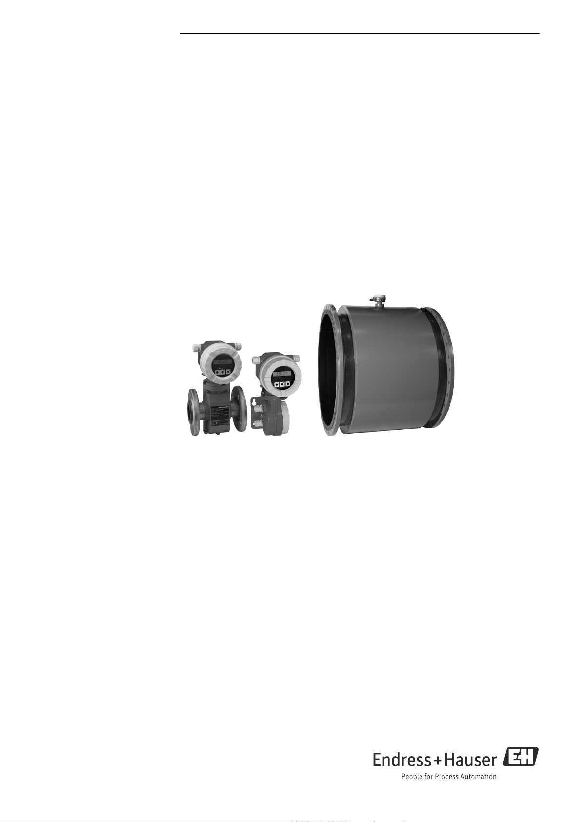
Proline Promag 10L
Electromagnetic flowmeter
The flowmeter with a weight-optimized sensor and highly cost-effectiveness
Application
• The measuring principle is virtually independent of pressure,
density, temperature and viscosity
• Fully suitable for standard applications in the water and
wastewater industry
Device properties
• Up to 30 % less sensor weight
• Nominal diameter: DN 25 to 2400 (1 to 90")
• Maximum reduced installation length to DVGW/ISO
• 2-line display with push buttons
• Device in compact or remote version
•HART
Your benefits
• Reduced installation costs – flexible mounting by one-of-akind lap-joint flange concept (DN < 350/14")
• Energy-saving flow measurement – no pressure loss due to
cross-section constriction
• Maintenance-free – no moving parts
• Cost-effective – designed for easy applications and direct
integration
• Safe operation – display provides easy readable process
information
• Fully industry compliant – IEC/EN/NAMUR
Page 2

Table of contents
Proline Promag 10L
Function and system design . . . . . . . . . . . . . . . . . . . . . .3
Measuring principle . . . . . . . . . . . . . . . . . . . . . . . . . . . . . . . . . . . 3
Measuring system . . . . . . . . . . . . . . . . . . . . . . . . . . . . . . . . . . . . . 3
Input . . . . . . . . . . . . . . . . . . . . . . . . . . . . . . . . . . . . . . . . . .4
Measured variable . . . . . . . . . . . . . . . . . . . . . . . . . . . . . . . . . . . . . 4
Measuring range . . . . . . . . . . . . . . . . . . . . . . . . . . . . . . . . . . . . . . 4
Operable flow range . . . . . . . . . . . . . . . . . . . . . . . . . . . . . . . . . . . 5
Output . . . . . . . . . . . . . . . . . . . . . . . . . . . . . . . . . . . . . . . . .6
Output signal . . . . . . . . . . . . . . . . . . . . . . . . . . . . . . . . . . . . . . . . . 6
Signal on alarm . . . . . . . . . . . . . . . . . . . . . . . . . . . . . . . . . . . . . . . 6
Load . . . . . . . . . . . . . . . . . . . . . . . . . . . . . . . . . . . . . . . . . . . . . . . . . 6
Low flow cutoff . . . . . . . . . . . . . . . . . . . . . . . . . . . . . . . . . . . . . . . 6
Galvanic isolation . . . . . . . . . . . . . . . . . . . . . . . . . . . . . . . . . . . . . 6
Power supply . . . . . . . . . . . . . . . . . . . . . . . . . . . . . . . . . . .6
Terminal assignment . . . . . . . . . . . . . . . . . . . . . . . . . . . . . . . . . . 6
Supply voltage . . . . . . . . . . . . . . . . . . . . . . . . . . . . . . . . . . . . . . . . 6
Power consumption . . . . . . . . . . . . . . . . . . . . . . . . . . . . . . . . . . . . 6
Power supply failure . . . . . . . . . . . . . . . . . . . . . . . . . . . . . . . . . . . 6
Electrical connection . . . . . . . . . . . . . . . . . . . . . . . . . . . . . . . . . . . 7
Electrical connection,
remote version . . . . . . . . . . . . . . . . . . . . . . . . . . . . . . . . . . . . . . . . 7
Potential equalization . . . . . . . . . . . . . . . . . . . . . . . . . . . . . . . . . . 7
Cable entry . . . . . . . . . . . . . . . . . . . . . . . . . . . . . . . . . . . . . . . . . . . 9
Cable specification . . . . . . . . . . . . . . . . . . . . . . . . . . . . . . . . . . . . . 9
Vibrations . . . . . . . . . . . . . . . . . . . . . . . . . . . . . . . . . . . . . . . . . . . 19
Mechanical construction . . . . . . . . . . . . . . . . . . . . . . . 20
Design, dimensions . . . . . . . . . . . . . . . . . . . . . . . . . . . . . . . . . . . 20
Weight . . . . . . . . . . . . . . . . . . . . . . . . . . . . . . . . . . . . . . . . . . . . . 31
Measuring tube specifications . . . . . . . . . . . . . . . . . . . . . . . . . . 35
Material . . . . . . . . . . . . . . . . . . . . . . . . . . . . . . . . . . . . . . . . . . . . 37
Fitted electrodes . . . . . . . . . . . . . . . . . . . . . . . . . . . . . . . . . . . . . 37
Process connections . . . . . . . . . . . . . . . . . . . . . . . . . . . . . . . . . . 37
Surface roughness . . . . . . . . . . . . . . . . . . . . . . . . . . . . . . . . . . . . 37
Operability . . . . . . . . . . . . . . . . . . . . . . . . . . . . . . . . . . . 38
Local operation . . . . . . . . . . . . . . . . . . . . . . . . . . . . . . . . . . . . . . 38
Remote operation . . . . . . . . . . . . . . . . . . . . . . . . . . . . . . . . . . . . 38
Certificates and approvals . . . . . . . . . . . . . . . . . . . . . . 38
CE mark . . . . . . . . . . . . . . . . . . . . . . . . . . . . . . . . . . . . . . . . . . . . 38
C-tick mark . . . . . . . . . . . . . . . . . . . . . . . . . . . . . . . . . . . . . . . . . . 38
Drinking water approval . . . . . . . . . . . . . . . . . . . . . . . . . . . . . . . 38
Other standards and guidelines . . . . . . . . . . . . . . . . . . . . . . . . . 38
Ordering information . . . . . . . . . . . . . . . . . . . . . . . . . . 39
Accessories . . . . . . . . . . . . . . . . . . . . . . . . . . . . . . . . . . . 39
Device-specific accessories . . . . . . . . . . . . . . . . . . . . . . . . . . . . . 39
Communication-specific accessories . . . . . . . . . . . . . . . . . . . . . 40
Service-specific accessories . . . . . . . . . . . . . . . . . . . . . . . . . . . . 40
Performance characteristics . . . . . . . . . . . . . . . . . . . . 10
Reference operating conditions . . . . . . . . . . . . . . . . . . . . . . . . . 10
Maximum measured error . . . . . . . . . . . . . . . . . . . . . . . . . . . . . 10
Repeatability . . . . . . . . . . . . . . . . . . . . . . . . . . . . . . . . . . . . . . . . 10
Installation . . . . . . . . . . . . . . . . . . . . . . . . . . . . . . . . . . . 11
Mounting location . . . . . . . . . . . . . . . . . . . . . . . . . . . . . . . . . . . . 11
Orientation . . . . . . . . . . . . . . . . . . . . . . . . . . . . . . . . . . . . . . . . . . 12
Inlet and outlet run . . . . . . . . . . . . . . . . . . . . . . . . . . . . . . . . . . . 13
Adapters . . . . . . . . . . . . . . . . . . . . . . . . . . . . . . . . . . . . . . . . . . . . 14
Length of connecting cable . . . . . . . . . . . . . . . . . . . . . . . . . . . . 15
Special mounting instructions . . . . . . . . . . . . . . . . . . . . . . . . . . 15
Environment . . . . . . . . . . . . . . . . . . . . . . . . . . . . . . . . . 16
Ambient temperature range . . . . . . . . . . . . . . . . . . . . . . . . . . . 16
Storage temperature . . . . . . . . . . . . . . . . . . . . . . . . . . . . . . . . . . 16
Degree of protection . . . . . . . . . . . . . . . . . . . . . . . . . . . . . . . . . . 16
Shock and vibration resistance . . . . . . . . . . . . . . . . . . . . . . . . . 16
Electromagnetic compatibility (EMC) . . . . . . . . . . . . . . . . . . . . 16
Process . . . . . . . . . . . . . . . . . . . . . . . . . . . . . . . . . . . . . . 17
Medium temperature range . . . . . . . . . . . . . . . . . . . . . . . . . . . . 17
Conductivity . . . . . . . . . . . . . . . . . . . . . . . . . . . . . . . . . . . . . . . . . 17
Pressure-temperature ratings . . . . . . . . . . . . . . . . . . . . . . . . . . 17
Medium pressure range (nominal pressure) . . . . . . . . . . . . . . 18
Pressure tightness . . . . . . . . . . . . . . . . . . . . . . . . . . . . . . . . . . . . 18
Limiting flow . . . . . . . . . . . . . . . . . . . . . . . . . . . . . . . . . . . . . . . . 19
Pressure loss . . . . . . . . . . . . . . . . . . . . . . . . . . . . . . . . . . . . . . . . . 19
Documentation . . . . . . . . . . . . . . . . . . . . . . . . . . . . . . . 40
Registered trademarks . . . . . . . . . . . . . . . . . . . . . . . . . 41
2 Endress+Hauser
Page 3
Proline Promag 10L
I
L
B
I
U
e
v
Function and system design
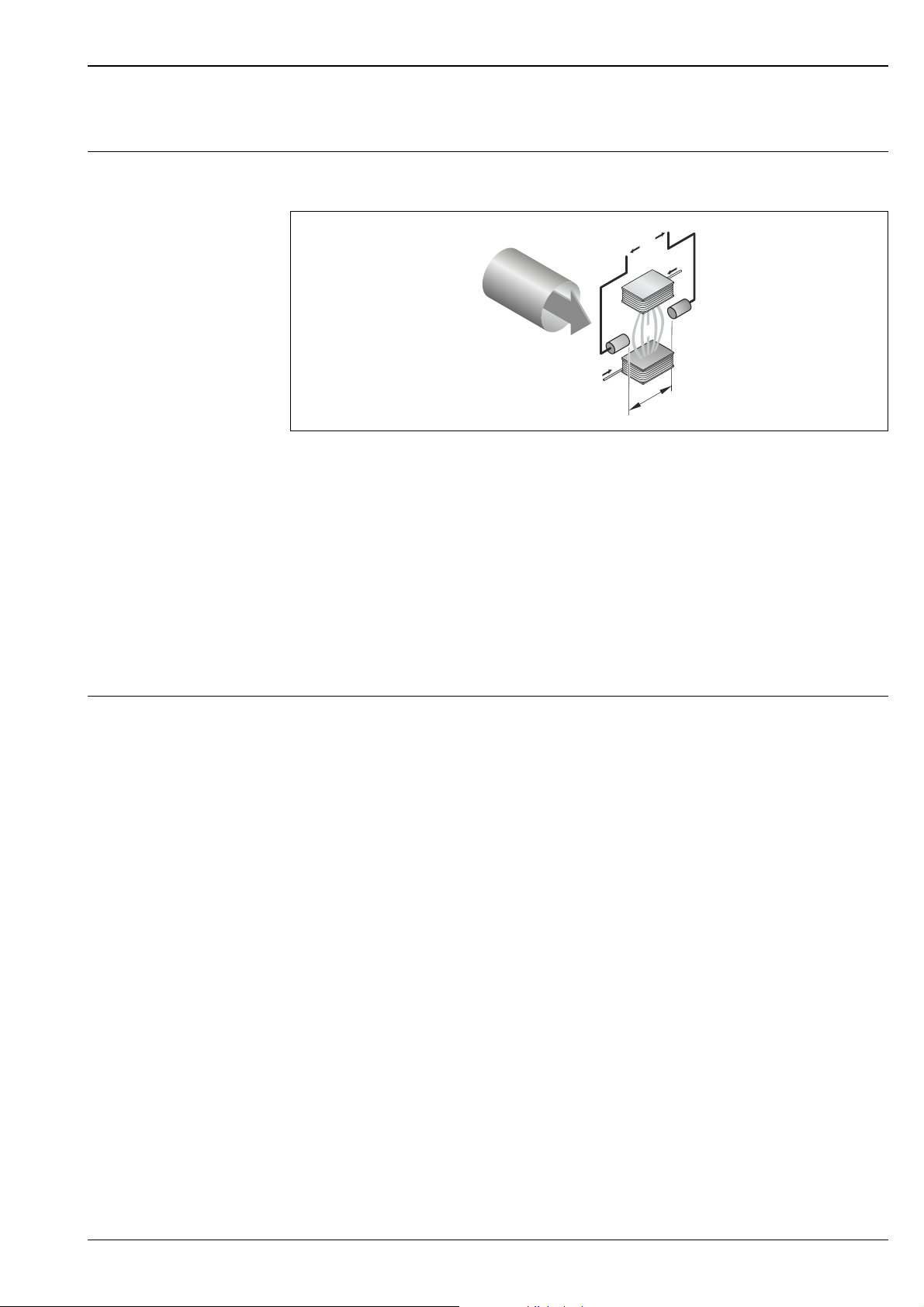
Measuring principle Following Faraday's law of magnetic induction, a voltage is induced in a conductor moving through a
magnetic field.
A0017035
Ue Induced voltage
B Magnetic induction (magnetic field)
L Electrode spacing
I Current
v Flow velocity
In the electromagnetic measuring principle, the flowing medium is the moving conductor.
The voltage induced (U
) is proportional to the flow velocity (v) and is supplied to the amplifier by
e
means of two measuring electrodes. The flow volume (Q) is calculated via the pipe cross-section (A).
The DC magnetic field is created through a switched direct current of alternating polarity.
Formulae for calculation:
• Induced voltage Ue = B · L · v
• Volume flow Q = A · v
Measuring system The measuring system consists of a transmitter and a sensor.
Two versions are available:
• Compact version: Transmitter and sensor form a mechanical unit.
• Remote version: Sensor is mounted separate from the transmitter.
Transmitter:
• Promag 10 (key operation, two-line, unilluminated display)
Sensor:
•Promag L
– DN 25 to 300 (1 to 12")
– DN 350 to 2400 (14 to 90")
!
Note!
To avoid corrosion, the sensor and process connection material must be selected considering the
environmental and process conditions.
Endress+Hauser 3
Page 4
Input
Measured variable Flow velocity (proportional to induced voltage)
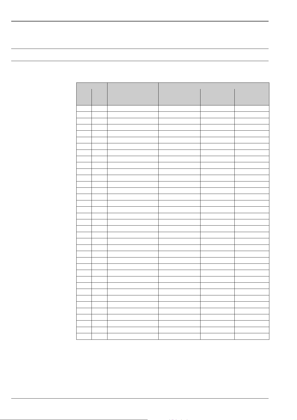
Measuring range Measuring ranges for liquids
Typically v = 0.01 to 10 m/s (0.03 to 33 ft/s) with the specified accuracy
Flow characteristic values (SI units)
Diameter Recommended flow Factory settings
Min./max. full scale value
(v ~ 0.3 or 10 m/s)
[mm] [inch]
25 1" 9 to 300 dm³/min 75 dm³/min 0.50 dm³ 1 dm³/min
32 – 15 to 500dm³/min 125dm³/min 1.00dm³ 2dm³/min
40 1 ½" 25 to 700 dm³/min 200 dm³/min 1.50 dm³ 3 dm³/min
50 2" 35 to 1100 dm³/min 300 dm³/min 2.50 dm³ 5 dm³/min
65 – 60 to 2000 dm³/min 500 dm³/min 5.00 dm³ 8 dm³/min
80 3" 90 to 3000 dm³/min 750 dm³/min 5.00 dm³ 12 dm³/min
100 4" 145 to 4700 dm³/min 1200 dm³/min 10.00 dm³ 20 dm³/min
125 – 220 to 7500 dm³/min 1850 dm³/min 15.00 dm³ 30 dm³/min
150 6" 20 to 600 m³/h 150 m³/h 0.025 m³ 2.5 m³/h
200 8" 35 to 1100 m³/h 300 m³/h 0.05 m³ 5.0 m³/h
250 10" 55 to 1700 m³/h 500 m³/h 0.05 m³ 7.5 m³/h
300 12" 80 to 2400 m³/h 750 m³/h 0.10 m³ 10 m³/h
350 14" 110 to 3300 m³/h 1000 m³/h 0.10 m³ 15 m³/h
375 15" 140 to 4200 m³/h 1200 m³/h 0.15 m³ 20 m³/h
400 16" 140 to 4200 m³/h 1200 m³/h 0.15 m³ 20 m³/h
450 18" 180 to 5400 m³/h 1500 m³/h 0.25 m³ 25 m³/h
500 20" 220 to 6600 m³/h 2000 m³/h 0.25 m³ 30 m³/h
600 24" 310 to 9600 m³/h 2500 m³/h 0.30 m³ 40 m³/h
700 28" 420 to 13500 m³/h 3500 m³/h 0.50 m³ 50 m³/h
750 30" 490 to 15000 m³/h 4000 m³/h 0.50 m³ 60 m³/h
800 32" 550 to 18000 m³/h 4500 m³/h 0.75 m³ 75 m³/h
900 36" 690 to 22500 m³/h 6000 m³/h 0.75 m³ 100 m³/h
1000 40" 850 to 28000 m³/h 7000 m³/h 1.00 m³ 125 m³/h
– 42" 950 to 30000 m³/h 8000 m³/h 1.00 m³ 125 m³/h
1200 48" 1250 to 40000 m³/h 10000 m³/h 1.50 m³ 150 m³/h
– 54" 1550 to 50000 m³/h 13000 m³/h 1.50 m³ 200 m³/h
1400 – 1700 to 55000 m³/h 14000 m³/h 2.00 m³ 225 m³/h
– 60" 1950 to 60000 m³/h 16000 m³/h 2.00 m³ 250 m³/h
1600 – 2200 to 70000 m³/h 18000 m³/h 2.50 m³ 300 m³/h
– 66" 2500 to 80000 m³/h 20500 m³/h 2.50 m³ 325 m³/h
1800 72" 2850 to 90000 m³/h 23000 m³/h 3.00 m³ 350 m³/h
– 78" 3300 to 100000 m³/h 28500 m³/h 3.50 m³ 450 m³/h
2000 – 3400 to 110000 m³/h 28500 m³/h 3.50 m³ 450 m³/h
– 84" 3700 to 125000 m³/h 31000 m³/h 4.50 m³ 500 m³/h
2200 – 4100 to 136000 m³/h 34000 m³/h 4.50 m³ 540 m³/h
– 90" 4300 to 143000 m³/h 36000 m³/h 5.00 m³ 570 m³/h
2400 – 4800 to 162000 m³/h 40000 m³/h 5.50 m³ 650 m³/h
Full scale value
Current output
(v ~ 2.5 m/s)
Pulse value
(~ 2 pulses/s)
Proline Promag 10L
Low flow cut off
(v ~ 0.04 m/s)
4 Endress+Hauser
Page 5
Proline Promag 10L
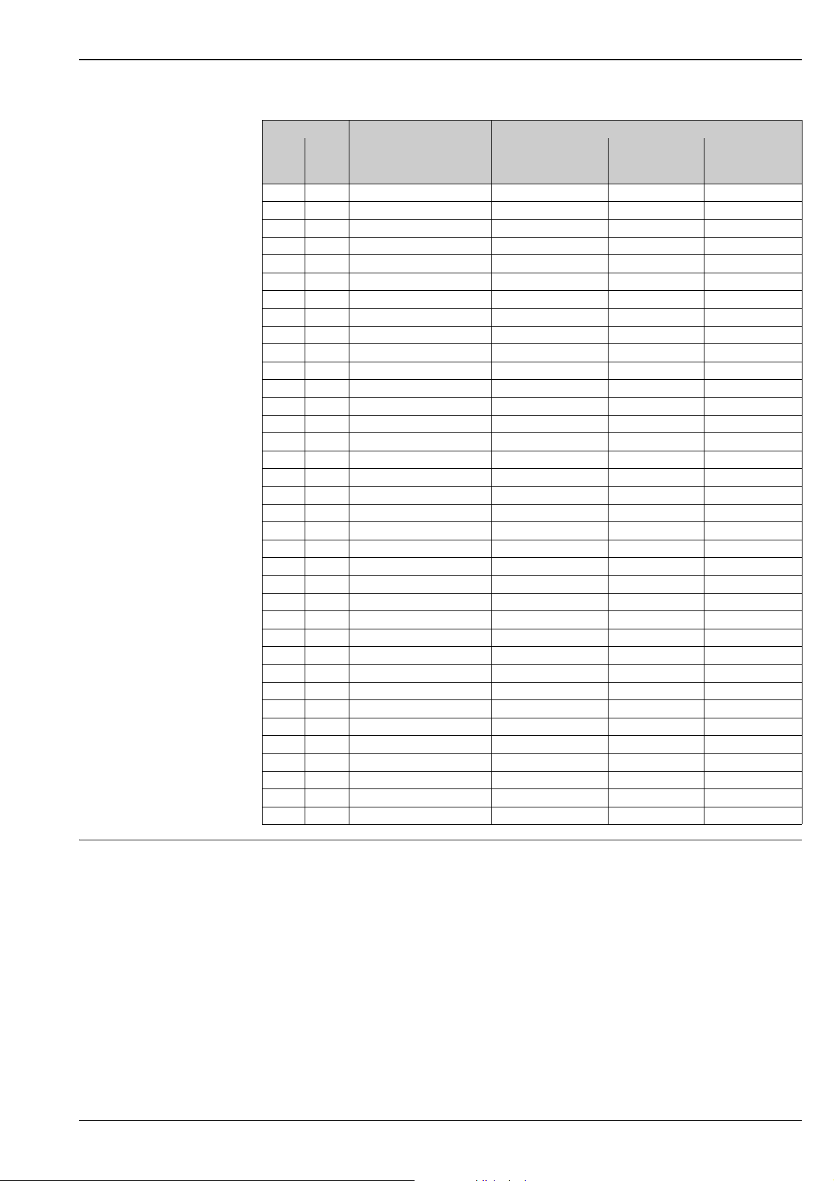
Flow characteristic values (US units)
Diameter Recommended flow rate Factory settings
Min./max. full scale value
(v ~ 0.3 or 10 m/s)
[inch] [mm]
1 25 2.5 to 80 gal/min 18 gal/min 0.20 gal 0.25 gal/min
1 ½" 40 7 to 190 gal/min 50 gal/min 0.50 gal 0.75 gal/min
2" 50 10 to 300 gal/min 75 gal/min 0.50 gal 1.25 gal/min
– 65 16 to 500 gal/min 130 gal/min 1 gal 2.0 gal/min
3" 80 24 to 800 gal/min 200 gal/min 2 gal 2.5 gal/min
4" 100 40 to 1250 gal/min 300 gal/min 2 gal 4.0 gal/min
– 125 60 to 1950 gal/min 450 gal/min 5 gal 7.0 gal/min
6" 150 90 to 2650 gal/min 600 gal/min 5 gal 12 gal/min
8" 200 155 to 4850 gal/min 1200 gal/min 10 gal 15 gal/min
10" 250 250 to 7500 gal/min 1500 gal/min 15 gal 30 gal/min
12" 300 350 to 10600 gal/min 2400 gal/min 25 gal 45 gal/min
14" 350 500 to 15000 gal/min 3600 gal/min 30 gal 60 gal/min
15" 375 600 to 19000 gal/min 4800 gal/min 50 gal 60 gal/min
16" 400 600 to 19000 gal/min 4800 gal/min 50 gal 60 gal/min
18" 450 800 to 24000 gal/min 6000 gal/min 50 gal 90 gal/min
20" 500 1000 to 30000 gal/min 7500 gal/min 75 gal 120 gal/min
24" 600 1400 to 44000 gal/min 10500 gal/min 100 gal 180 gal/min
28" 700 1900 to 60000 gal/min 13500 gal/min 125 gal 210 gal/min
30" 750 2150 to 67000 gal/min 16500 gal/min 150 gal 270 gal/min
32" 800 2450 to 80000 gal/min 19500 gal/min 200 gal 300 gal/min
36" 900 3100 to 100000 gal/min 24000 gal/min 225 gal 360 gal/min
40" 1000 3800 to 125000 gal/min 30000 gal/min 250 gal 480 gal/min
42" – 4200 to 135000 gal/min 33000 gal/min 250 gal 600 gal/min
48" 1200 5500 to 175000 gal/min 42000 gal/min 400 gal 600 gal/min
54" – 9 to 300 Mgal/day 75 Mgal/day 0.0005 Mgal 1.3 Mgal/min
– 1400 10 to 340 Mgal/day 85 Mgal/day 0.0005 Mgal 1.3 Mgal/min
60" – 12 to 380 Mgal/day 95 Mgal/day 0.0005 Mgal 1.3 Mgal/min
– 1600 13 to 450 Mgal/day 110 Mgal/day 0.0008 Mgal 1.7 Mgal/min
66" – 14 to 500 Mgal/day 120 Mgal/day 0.0008 Mgal 2.2 Mgal/min
72" 1800 16 to 570 Mgal/day 140 Mgal/day 0.0008 Mgal 2.6 Mgal/min
78" – 18 to 650 Mgal/day 175 Mgal/day 0.0010 Mgal 3.0 Mgal/min
– 2000
84" – 24 to 800 Mgal/day 190 Mgal/day 0.0011 Mgal 3.2 Mgal/day
– 2200 26 to 870 Mgal/day 210 Mgal/day 0.0012 Mgal 3.4 Mgal/day
90" – 27 to 910 Mgal/day 220 Mgal/day 0.0013 Mgal 3.6 Mgal/day
– 2400 31 to 1030 Mgal/day 245 Mgal/day 0.0014 Mgal 4.1 Mgal/day
20 to 700 Mgal/day 175 Mgal/day 0.0010 Mgal 2.9 Mgal/day
Full scale value
Current output
(v ~ 2.5 m/s)
Pulse value
(~ 2 pulses/s)
Low flow cut off
(v ~ 0.04 m/s)
Operable flow range Over 1000 : 1
Endress+Hauser 5
Page 6
Proline Promag 10L
Output
Output signal Current output
• Galvanically isolated
• Active: 4 to 20 mA, RL < 700 Ω (for HART: RL ≥ 250 Ω)
• Full scale value adjustable
• Temperature coefficient: typ. 2 μA/°C, resolution: 1.5 μA
Pulse/status output
• Galvanically isolated
• Passive: 30 V DC / 250 mA
• Open collector
• Can be configured as:
– Pulse output: Pulse value and pulse polarity can be selected, max. pulse width adjustable
(5 to 2000 ms), pulse frequency max. 100 Hz
– Status output: for example, can be configured for error messages, empty pipe detection, flow
recognition, limit value
Signal on alarm • Current output → Failsafe mode can be selected (e.g. in accordance with NAMUR Recommendation
NE 43)
• Pulse output → Failsafe mode can be selected
• Status output → "Not conductive" in the event of fault or power supply failure
Load → Section "output signal"
Low flow cutoff Switch-on points for low flow are selectable.
Galvanic isolation All circuits for inputs, outputs and power supply are galvanically isolated from each other.
Power supply
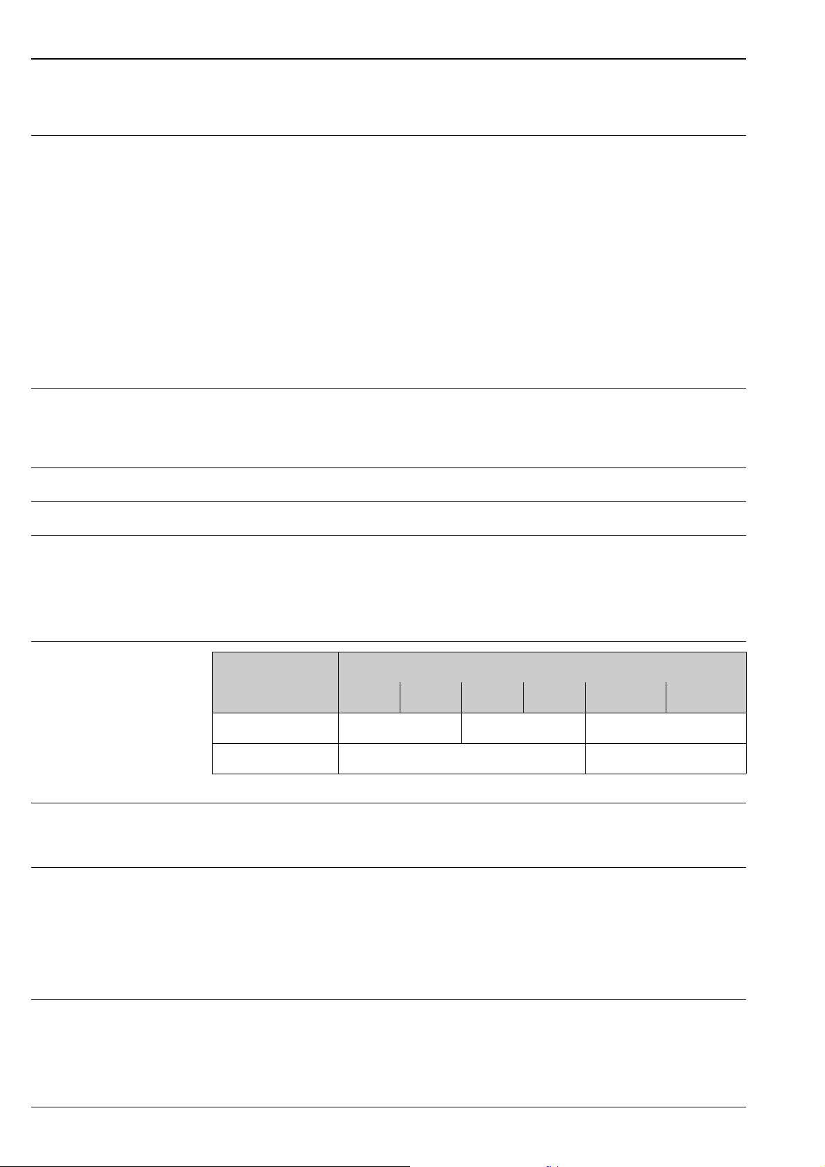
Terminal assignment
Supply voltage • 85 to 250 V AC, 45 to 65 Hz
Power consumption • 11 to 40 V DC: < 6 W (incl. sensor)
Order code for
"Input/Output"
24 (+) 25 (–) 26 (+) 27 (–) 1 (L1/L+) 2 (N/L–)
A Pulse/status output HART current output Power supply
Functional values → 6, Section "Output signal" → Section "Supply voltage"
• 20 to 28 V AC, 45 to 65 Hz
• 11 to 40 V DC
• 20 to 28 V AC: < 8 VA (incl. sensor)
• 85 to 250 V AC: < 12 VA (incl. sensor)
Switch-on current:
• Max. 3.3 A (< 5 ms) for 24 V DC
• Max. 5.5 A (< 5 ms) for 28 V AC
• Max. 16 A (< 5 ms) for 250 V AC
Terminal No.
Power supply failure Lasting min. ½ cycle frequency: EEPROM saves measuring system data
6 Endress+Hauser
Page 7
Proline Promag 10L
b
a
e
e
b
2127
–
25–26
+
24
+
L1
(L+)
N
(L-)
e
g
b
d
h
i
c
f
b
n.c.
S1
E1
E2
S2
GND
E
S
42 41
6
5
7
8
4
37 36
dc
a
d
c
E1
E2
E
5
7
4
37
42 41
n.c. n.c.
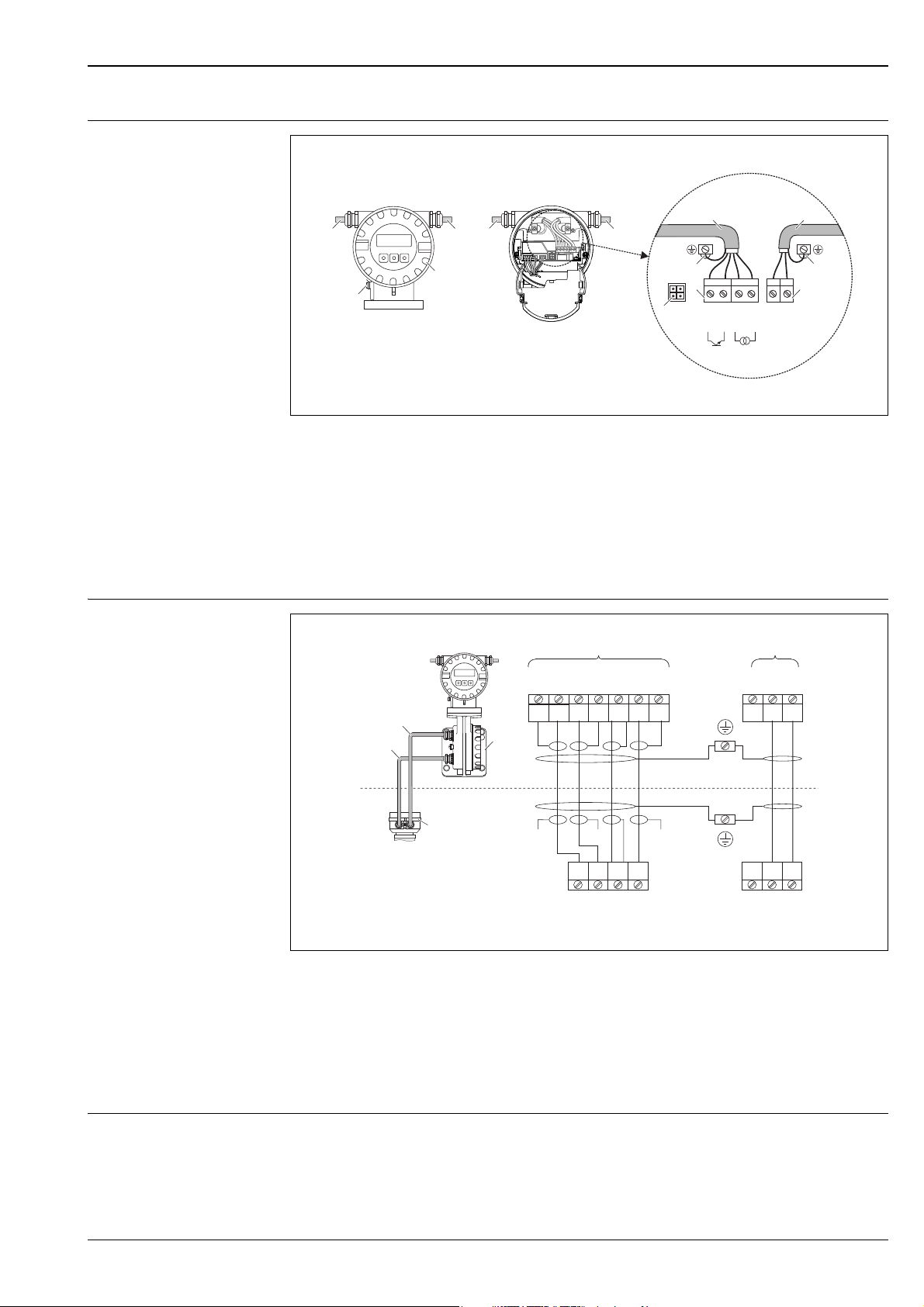
Electrical connection
Connecting the transmitter (aluminum field housing), cable cross-section max. 2.5 mm2 (14 AWG)
a Electronics compartment cover
bPower supply cable
c Ground terminal for power supply cable
d Terminal connector for power supply cable
e Electrode cable
f Ground terminal for electrode cable
g Terminal connector for electrode cable
h Service connector
i Ground terminal for potential equalization
A0003192
Electrical connection, remote version
A0012461
Connecting the remote version
a Wall-mount housing connection compartment
b Sensor connection housing cover
c Electrode cable
d Coil current cable
n.c. Not connected, insulated cable shields
Potential equalization
!
Terminal numbers and cable colors:
5/6=brown, 7/8=white, 4=green, 37/36=yellow
Note!
The measuring system must be included in the potential equalization.
Perfect measurement is only ensured when the fluid and the sensor have the same electrical potential.
This is ensured by the reference electrode integrated in the sensor as standard.
Endress+Hauser 7
Page 8
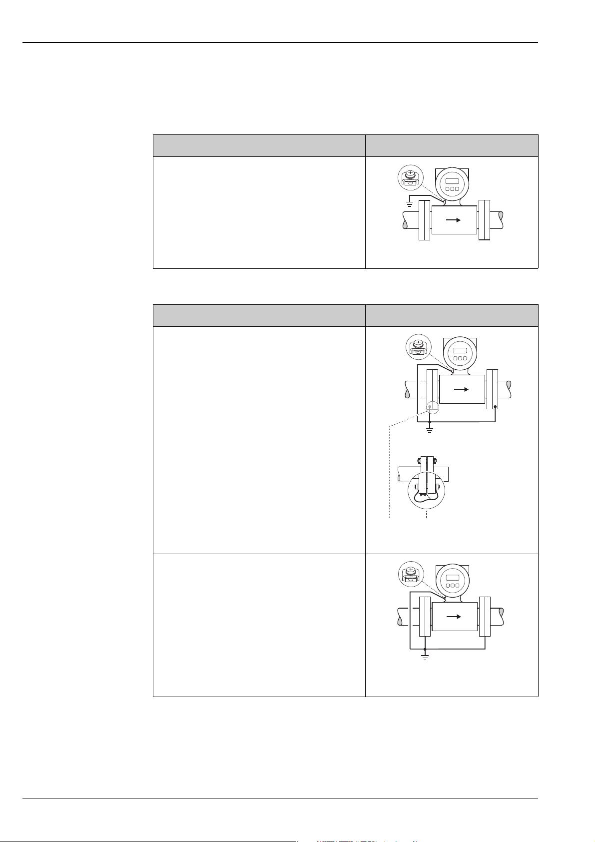
The following should also be taken into consideration for potential equalization:
• Internal grounding concepts in the company
• Operating conditions, such as the material/ grounding of the pipes (see table)
Standard situation
Operating conditions Potential equalization
When using the measuring device in a:
• Metal, grounded pipe
Potential equalization takes place via the ground terminal
of the transmitter.
Note!
!
When installing in metal pipes, we recommend you connect
the ground terminal of the transmitter housing with the
piping.
Via the ground terminal of the transmitter
Special situations
Operating conditions Potential equalization
Proline Promag 10L
A0010831
When using the measuring device in a:
• Metal pipe that is not grounded
This connection method also applies in situations where:
• Customary potential equalization cannot be ensured.
• Excessively high equalizing currents can be expected.
Both sensor flanges are connected to the pipe flange by
means of a ground cable (copper wire, at least 6 mm² /
0.0093 in²) and grounded. Connect the transmitter or
sensor connection housing, as applicable, to ground
potential by means of the ground terminal provided for the
purpose.
The ground cable is mounted directly on the conductive
flange coating with the flange screws.
Note!
!
The ground cable for flange-to-flange connections can be
ordered separately as an accessory from Endress+Hauser.
When using the measuring device in a:
• Plastic pipe
• Pipe with insulating lining
This connection method also applies in situations where:
• Customary potential equalization cannot be ensured.
• Excessively high equalizing currents can be expected.
Potential equalization takes place using additional ground
disks, which are connected to the ground terminal via a
ground cable (copper wire, at least 6 mm² / 0.0093 in²).
When installing the ground disks, please comply with the
enclosed Installation Instructions.
A0011567
Via the ground terminal of the transmitter and the
flanges of the pipe
A0010833
Via the ground terminal of the transmitter and the
optionally available ground disks
8 Endress+Hauser
Page 9
Proline Promag 10L
1
2 2
1
2
3
4
5
6
7
a
b
Operating conditions Potential equalization
When using the measuring device in a:
• Pipe with a cathodic protection unit
The device is installed potential-free in the pipe.
Only the two flanges of the pipe are connected with a
ground cable (copper wire, at least 6 mm² / 0.0093 in²).
Here, the ground cable is mounted directly on the
conductive flange coating with flange screws.
Note the following when installing:
• The applicable regulations regarding potential-free
installation must be observed.
•There should be no electrically conductive connection
between the pipe and the device.
• The mounting material must withstand the applicable
torques.
Cable entry Power supply and electrode cables (inputs/ outputs):
• Cable entry M20 × 1.5 (8 to 12 mm / 0.31 to 0.47")
• Thread for cable entries, ½" NPT, G ½"
Connecting cable for remote version:
• Cable entry M20 × 1.5 (8 to 12 mm / 0.31 to 0.47")
• Thread for cable entries, ½" NPT, G ½"
Potential equalization and cathodic protection
1 Power supply isolation transformer
2 Electrically isolated
A0010834
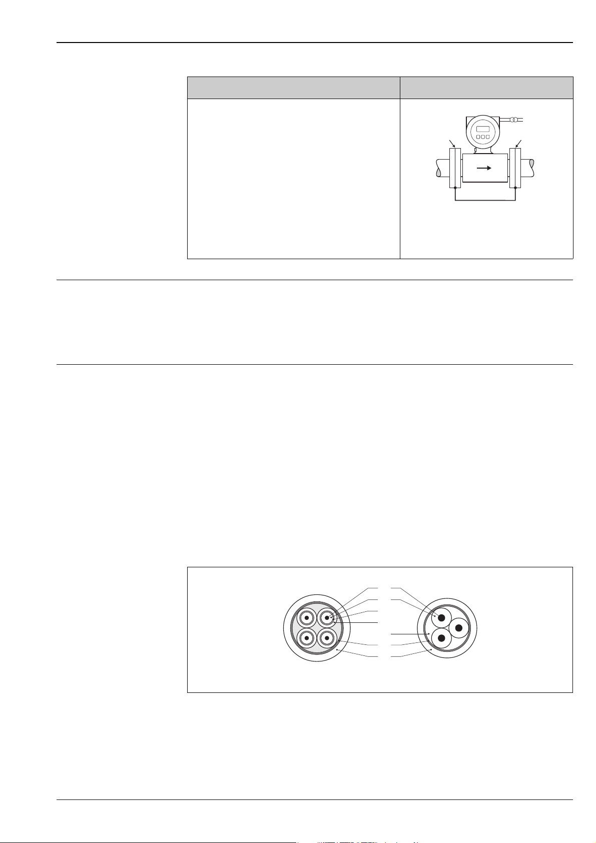
Cable specification Coil current cable
• 3 × 0.75 mm
2
(18 AWG) PVC cable with common, braided copper shield (⌀ ~ 9 mm / 0.35")
• Conductor resistance: ≤ 37 Ω/km (≤ 0.011 Ω/ft)
• Capacitance core/core, shield grounded: ≤ 120 pF/m (≤ 37 pF/ft)
• Operating temperature: –20 to +80 °C (–68 to +176 °F)
• Cable cross-section: max. 2.5 mm
• Test voltage for cable insulation: ≤ 1433 AC r.m.s. 50/60 Hz or ≥ 2026 V DC
Electrode cable
• 3 × 0.38 mm2 (20 AWG) PVC cable with common, braided copper shield (⌀ ~ 9.5 mm / 0.37") and
individual shielded cores
• With empty pipe detection (EPD): 4 × 0.38 mm
shield (⌀ ~ 9.5 mm / 0.37") and individual shielded cores
• Conductor resistance: ≤ 50 Ω/km (≤ 0.015 Ω/ft)
• Capacitance core/shield: ≤ 420 pF/m (≤ 128 pF/ft)
• Operating temperature: –20 to +80 °C (–68 to +176 °F)
• Cable cross-section: max. 2.5 mm
2
(14 AWG)
2
(14 AWG)
2
(20 AWG) PVC cable with common, braided copper
Endress+Hauser 9
A0003194
a Electrode cable
b Coil current cable
1Core
2 Core insulation
3 Core shield
4 Core jacket
5 Core reinforcement
6 Cable shield
7 Outer jacket
Page 10
!
2.5
[%]
2.0
1.5
1.0
0.5
0
0.5 %
0
1
2 4 6 8 10 [m/s]
v
5 10 15 20 25 30 32 [ft/s]0
Proline Promag 10L
Operation in zones of severe electrical interference
The measuring device complies with the general safety requirements in accordance with EN 61010
and the EMC requirements of IEC/EN 61326.
Note!
Grounding is by means of the ground terminals provided for the purpose inside the connection
housing. Ensure that the stripped and twisted lengths of cable shield to the ground terminal are as
short as possible.
Performance characteristics
Reference operating conditions
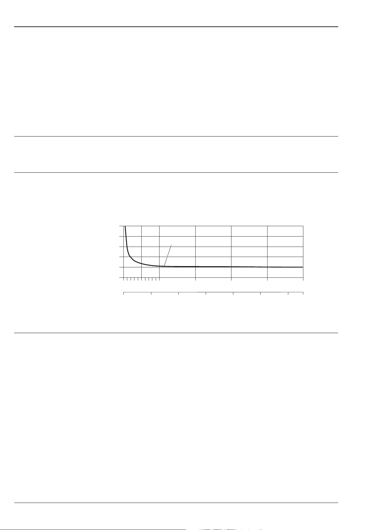
Maximum measured error • Current output: also typically ± 5 μA
• Error limits following DIN EN 29104, future ISO 20456
• Water, typically +15 to +45°C (+59 to +113 °F); 0.5 to 7 bar (73 to 101 psi)
• Specification as per calibration protocol
• Data on the measured error based on accredited calibration rigs traced back to ISO 17025
• Pulse output: ±0.5% o.r. ± 2 mm/s (±0.5% o.r. ± 0.08 in/s) (o.r. = of reading)
Fluctuations in the supply voltage do not have any effect within the specified range.
Max. measured error in % of reading
A0003200
Repeatability Max. ±0.2% o.r. ± 2 mm/s (±0.2% o.r. ± 0.08 in/s) (o.r. = of reading)
10 Endress+Hauser
Page 11
Proline Promag 10L
h2DN³´
Installation
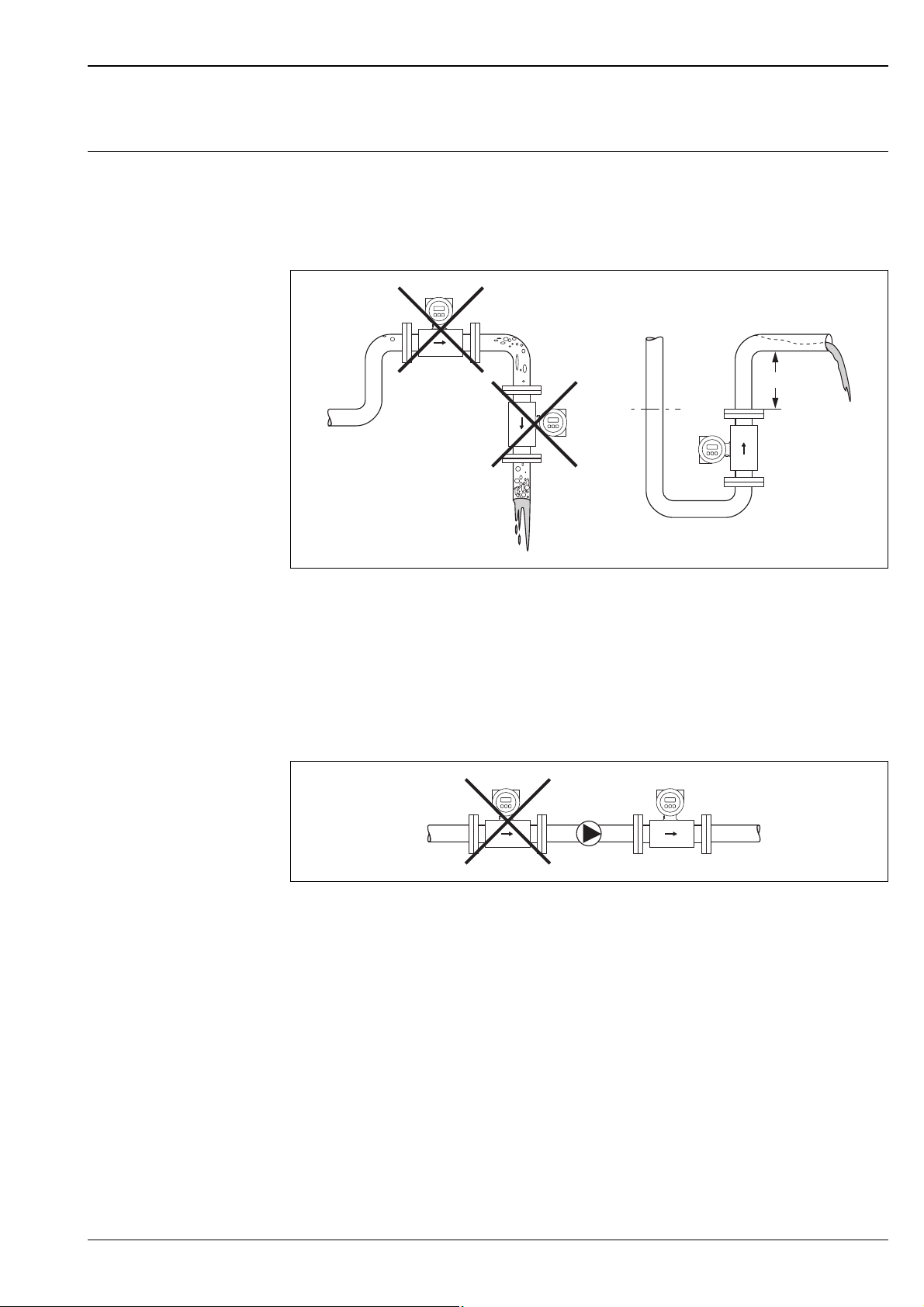
Mounting location Entrained air or gas bubble formation in the measuring tube can result in an increase in measuring
errors.
Avoid the following installation locations in the pipe:
• Highest point of a pipeline. Risk of air accumulating!
• Directly upstream from a free pipe outlet in a vertical pipeline.
!
A0003202
Mounting location
Installation of pumps
Sensors may not be installed on the pump suction side. This precaution is to avoid low pressure and the
consequent risk of damage to the lining of the measuring tube. Information on the pressure tightness
of the measuring tube lining → 17, Section "Pressure tightness".
Pulsation dampers may be needed when using piston pumps, piston diaphragm pumps or hose pumps.
Information on the shock and vibration resistance of the measuring system → 16, Section "Shock and
vibration resistance".
A0003203
Installation of pumps
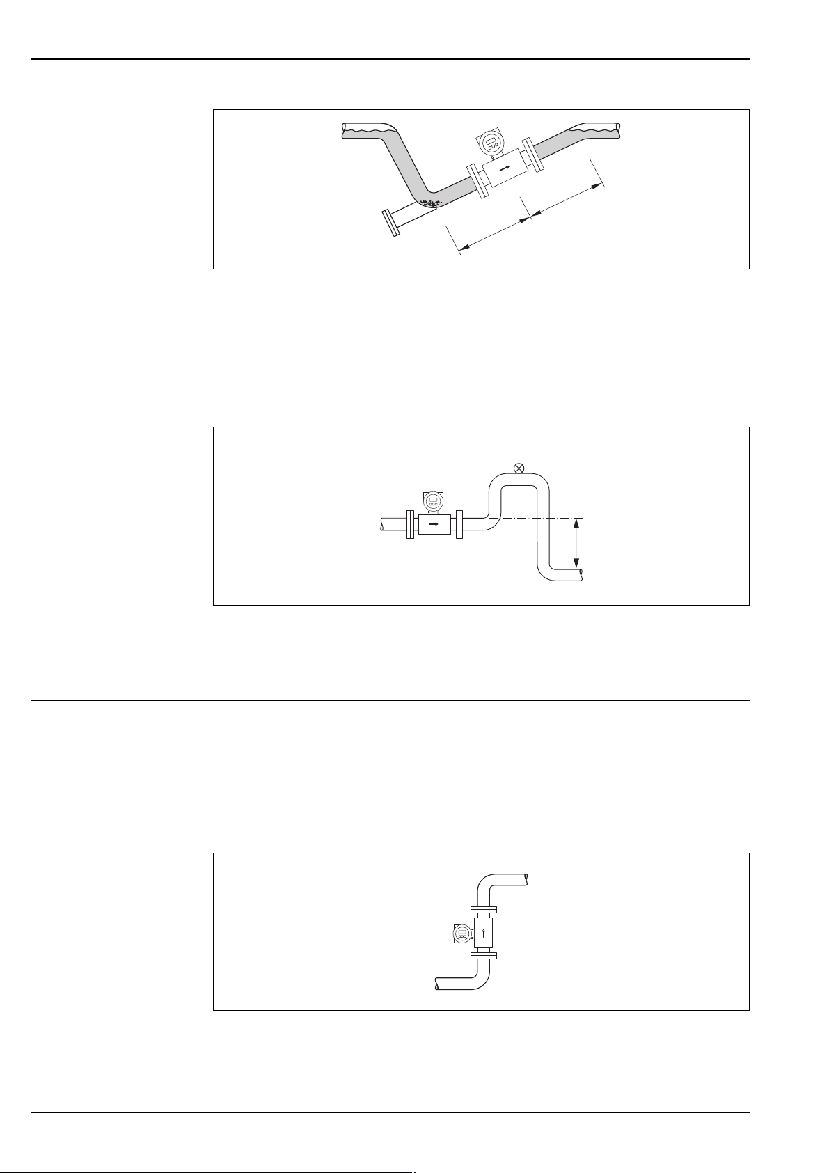
Partially filled pipes
Partially filled pipes with gradients necessitate a drain-type configuration.
The empty pipe detection function (EPD) provides additional security in detecting empty or partially
filled pipes.
Note!
Risk of solids accumulating. Do not install the sensor at the lowest point in the drain. It is advisable to
install a cleaning valve.
Endress+Hauser 11
Page 12
Proline Promag 10L
³´5DN
³ 2
´ DN
h
2
1
A0003204
Installation with partially filled pipes
Down pipes
Install a siphon or a vent valve downstream of the sensor in down pipes h ≥ 5 m (16.4 ft). This
precaution is to avoid low pressure and the consequent risk of damage to the lining of the measuring
tube. This measure also prevents the liquid current stopping in the pipe which could cause air locks.
Information on the pressure tightness of the measuring tube lining → 17, Section "Pressure
tightness".
A0008157
Installation measures for vertical pipes
1Vent valve
2Pipe siphon
h Length of the down pipe
Orientation An optimum orientation helps avoid gas and air accumulations and deposits in the measuring tube.
However, the measuring device also offers the additional function of empty pipe detection (EPD) for
detecting partially filled measuring tubes or if outgassing fluids or fluctuating operating pressures are
present.
Vertical orientation
This is the ideal orientation for self-emptying piping systems and for use in conjunction with empty
pipe detection.
A0008158
Vertical orientation
12 Endress+Hauser
Page 13
Proline Promag 10L
A
1
22
A
3
³ 5DNx
³ 2DNx
!
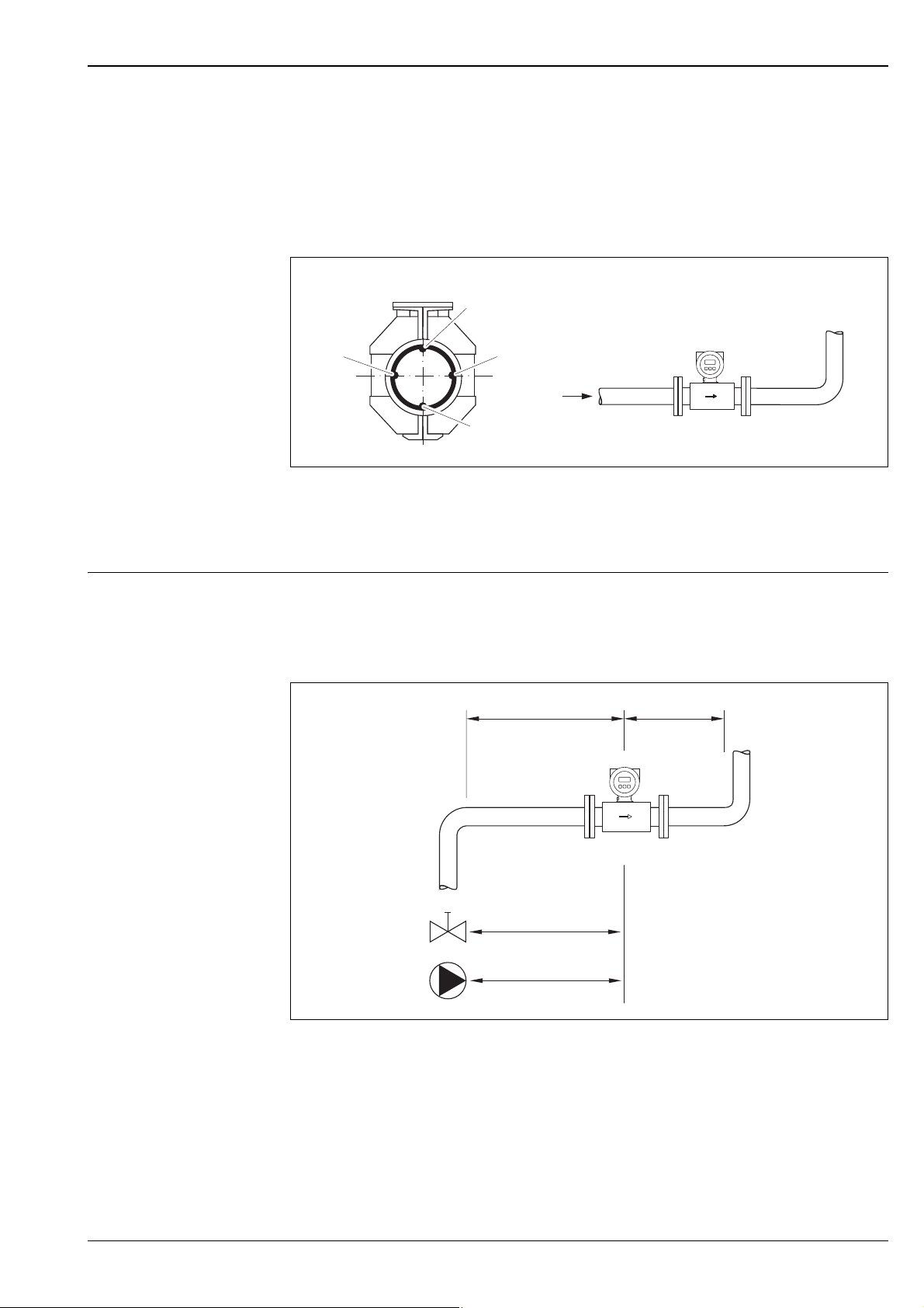
Horizontal orientation
The measuring electrode axis should be horizontal. This prevents brief insulation of the two measuring
electrodes by entrained air bubbles.
Note!
Empty pipe detection only works correctly with horizontal orientation if the transmitter housing is
facing upwards. Otherwise there is no guarantee that empty pipe detection will respond if the
measuring tube is only partially filled or empty.
A0003207
Horizontal orientation
1 EPD electrode for empty pipe detection
2 Measuring electrodes for signal detection
3 Reference electrode for potential equalization
Inlet and outlet run If possible, install the sensor well clear of assemblies such as valves, T-pieces, elbows etc.
Note the following inlet and outlet runs to comply with measuring accuracy specifications:
• Inlet run: ≥ 5 × DN
•Outlet run: ≥ 2 × DN
Inlet and outlet run
A0003210
Endress+Hauser 13
Page 14
Proline Promag 10L
100
10
0.5
d / D
[mbar]
0.6 0.7 0.8 0.9
1 m/s
2 m/s
3 m/s
4 m/s
5 m/s
6 m/s
7 m/s
8 m/s
1
D
d
max. 8°
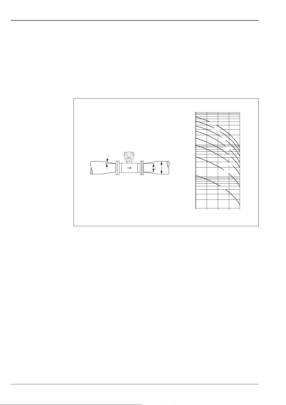
Adapters Suitable adapters to DIN EN 545 (double-flange reducers) can be used to install the sensor in larger-
diameter pipes. The resultant increase in the rate of flow improves measuring accuracy with very slowmoving fluids. The nomogram shown here can be used to calculate the pressure loss caused by reducers
and expanders.
!
Note!
The nomogram only applies to liquids of viscosity similar to water.
1. Calculate the ratio of the diameters d/D.
2. From the nomogram read off the pressure loss as a function of flow velocity (downstream from
the reduction) and the d/D ratio.
A0003213
Pressure loss due to adapters
14 Endress+Hauser
Page 15

Proline Promag 10L
L
max
[]ft
200 6000
400
200
100
50 100 200
[m]
[ S/cm]μ
L
max
50
≤≤3 ( 10)
Length of connecting cable When mounting the remote version, please note the following to achieve correct measuring results:
• Fix cable run or lay in armored conduit. Cable movements can falsify the measuring signal especially
in the case of low fluid conductivities.
• Route the cable well clear of electrical machines and switching elements.
• If necessary, ensure potential equalization between sensor and transmitter.
• The permitted cable length L
is determined by the fluid conductivity.
max
A minimum conductivity of 50 μS/cm is needed for all fluids.
• When the empty pipe detection function is switched on (EPD), the maximum connecting cable
length is 10 m (33 ft).
Special mounting instructions
Permitted length of connecting cable for remote version
Area marked in gray = permitted range; L
= length of connecting cable in [m] ([ft]); fluid conductivity in [μS/cm]
max
Temporary use in water
A remote version in IP67, type 6 is optionally available for temporary use in water up to 168 hours at
≤ 3 m (10 ft) or, in exceptional cases, for use up to 48 hours at ≤ 10 m (30 ft).
Compared to the degree of protection of standard version IP67, type 4X enclosure, the version IP67,
type 6 enclosure was designed to withstand short-term or temporary submergence (e.g. flooding).
Engineering unit m (ft)
A0003214
A0017296
Endress+Hauser 15
Page 16

Proline Promag 10L
Environment
Ambient temperature range Transmitter
• –20 to +60 °C (–4 to +140 °F)
Sensor
• Flange material carbon steel: –10 to +60 °C (14 to +140 °F)
• Flange material stainless steel (DN ≤ 300/12"): –40 to +60 °C (–40 to +140 °F)
!
Storage temperature The storage temperature corresponds to the operating temperature range of the measuring
!
Note!
The permitted temperature range of the measuring tube lining may not be undershot or overshot
(→ 17, Section "Medium temperature range").
Please note the following points:
• Install the device in a shady location. Avoid direct sunlight, particularly in warm climatic regions.
• The transmitter must be mounted separate from the sensor if both the ambient and fluid
temperatures are high.
transmitter and the appropriate measuring sensors.
Note!
• The measuring device must be protected against direct sunlight during storage in order to avoid
unacceptably high surface temperatures.
• A storage location must be selected where moisture does not collect in the measuring device. This
will help prevent fungus and bacteria infestation which can damage the liner.
Degree of protection Transmitter
• As standard: IP67, type 4X enclosure
• When housing is open: IP20; type 1 enclosure
Sensor
• As standard: IP67, type 4X enclosure
• Optionally available for remote version:
– IP67, Type 6P enclosure. Suitable for temporary use in water up to 168 hours at ≤ 3 m (10 ft) or
up to 48 hours at ≤ 10 m (30 ft).
– IP68, Type 6P enclosure (for DN ≤ 300 (12") only possible in conjunction with stainless steel
flanges)
Not suitable for use in corrosive atmospheres/liquids or in buried applications if special
precautions are not taken.
Shock and vibration resistance
Electromagnetic compatibility (EMC)
Acceleration up to 2 g following IEC 600 68-2-6
• As per IEC/EN 61326 as well as NAMUR Recommendation NE 21
• Emission: to limit value for industry EN 55011
16 Endress+Hauser
Page 17

Proline Promag 10L
0
5
10
15
20
[bar][psi]
-60
-40
-20
020
40 60 80 100120140
[°C]
[°F]
0-40 100 200 300
200
100
300
0
Lapjoint PN16/Class150
Lapjoint flange, stampedplate PN10
Lapjoint PN10
0
5
10
15
20
[bar][psi]
-60
-40
-20
020
40 60 80 100120140
[°C]
[°F]
0-40 100 200 300
200
100
300
0
PN16
PN10
PN6
Process
Medium temperature range • 0 to +80 °C (+32 to +176 °F) for hard rubber (DN 350 to 2400 / 14 to 90")
• –20 to +50 °C (–4 to +122 °F) for polyurethane (DN 25 to 1200 / 1 to 48")
• –20 to +90 °C (–4 to +194 °F) for PTFE (DN 25 to 300 / 1 to 12")
Conductivity The minimum conductivity is: ≥ 50 μS/cm
!
Pressure-temperature ratings
!
Note!
In the remote version, the necessary minimum conductivity also depends on the cable length (→ 15,
Section "Length of connecting cable").
Note!
• The following diagrams contain allowable operating pressures as a function of the medium
temperature. However, the maximum medium temperatures permitted always depend on the lining
material of the sensor and/or the sealing material (→ 17).
• Permitted test pressure = 1.5 × nominal pressure
Process connection: lap joint flange/lap joint flange, stamped plate according to EN 1092-1
(DIN 2501) and ASME B16.5; DN 25 to 300 (1 to 12")
A0021399-EN
Process connection material: stainless steel (min. -40 °C (-40 °F)), carbon steel (min. -10 °C (+14 °F))
Process connection: flange according to EN 1092-1 (DIN 2501); DN 350 to 2400 (14 to 90")
A0025178-EN
Process connection material: carbon steel
Endress+Hauser 17
Page 18

Proline Promag 10L
0
5
10
15
20
[bar][psi]
-60
-40
-20
020
40 60 80 100120140
[°C]
[°F]
0-40 100 200 300
200
100
300
0
Class150
0
5
10
15
20
[bar][psi]
-60
-40
-20
020
40 60 80 100120140
[°C]
[°F]
0-40 100 200 300
200
100
300
0
TableE
PN16
Process connection: flange according to ASME B16.5; DN 350 to 600 (14 to 24")
Process connection material: A105
Process connection: flange according to AS 2129 and AS 4087; DN 350 to 2400 (14 to 90")
A0025179-EN
Process connection material: carbon steel
Medium pressure range (nominal pressure)
• EN 1092-1 (DIN 2501)
– PN 6 (DN 350 to 2400 / 14 to 90")
– PN 10 (DN 200 to 2400 / 8 to 90")
– PN 16 (DN 25 to 2000 / 1 to 78")
• EN 1092-1, lap joint flange, stamped plate
– PN 10 (DN 25 to 300 / 1 to 12")
•ASME B16.5
– Class 150 (1 to 24")
• AWWA C207
– Class D (28 to 90")
•AS2129
– Table E (350 to 1200 / 14 to 48")
•AS4087
– PN 16 (350 to 1200 / 14 to 48")
Pressure tightness Measuring tube lining: Polyurethane, hard rubber
Promag L
Nominal diameter
[mm] [inch]
25 to 1200 1 to 48" Polyurethane 0 0 –
350 to 2400 14 to 90" Hard rubber 0 0 0
18 Endress+Hauser
Measuring
tube lining
Resistance of measuring tube lining to partial vacuum: Limit values
for abs. pressure [mbar] ([psi]) at various fluid temperatures
25 °C 50 °C 80° C
77 °F 122 °F 176° F
A0025180-EN
Page 19

Proline Promag 10L
L
Measuring tube lining: PTFE
Nominal diameter Limit values for abs. pressure [mbar] ([psi]) at fluid temperatures:
25 °C (77 °F) 90 °C (194 °F)
[mm] [inch] [mbar] [psi] [mbar] [psi]
251"0000
32 – 0 0 0 0
401 ½"0000
502"0000
65 – 0 0 40 0.58
80 3" 0 0 40 0.58
100 4" 0 0 135 1.96
125 – 135 1.96 240 3.48
150 6" 135 1.96 240 3.48
200 8" 200 2.90 290 4.21
250 10" 330 4.79 400 5.80
300 12" 400 5.80 500 7.25
Limiting flow The diameter of the pipe and the flow rate determine the nominal diameter of the sensor.
The optimum flow velocity is between 2 to 3 m/s (6.5 to 9.8 ft/s). The velocity of flow (v), moreover,
has to be matched to the physical properties of the fluid:
• v < 2 m/s (6.5 ft/s): for abrasive fluids such as potter's clay, lime milk, ore slurry etc.
• v > 2 m/s (6.5 ft/s): for fluids causing build-up such as wastewater sludges etc.
For an overview of the measuring range full scale values, see the "Measuring range" section → 4.
Pressure loss • No pressure loss if the sensor is installed in a pipe with the same nominal diameter.
• Pressure losses for configurations incorporating adapters according to DIN EN 545 (→ 14, Section
"Adapters").
Vibrations Secure the piping and the sensor if vibration is severe.
!
Note!
If vibrations are too severe, we recommend the sensor and transmitter be mounted separately.
Information on the permitted shock and vibration resistance → 16, Section "Shock and vibration
resistance".
A0003208
Measures to prevent vibration of the measuring device
L > 10 m (33 ft)
Endress+Hauser 19
Page 20

Mechanical construction
K
F
E
D
A
H
L
N
O
P
J
G
B
C
M
248 ±2
(9.76 ±0.08)
238 (9.37)
AB
ANSCHLUSSKLEMMEN - FIELD TERMINALS
Design, dimensions Transmitter, remote version
Proline Promag 10L
Transmitter dimensions, remote version
Dimensions in SI units
A B C D E F G Ø H
178 113 135 20 to 30 161 to 181 113 100 8.6 (M8)
J K L M N O P
123 150 100 25 133 177.5 327.5
All dimensions in [mm]
Dimensions in US units
A B C D E F G Ø H
7.00 4.45 5.31 0.79 to 1.81 6.34 to 7.13 4.44 3.94 0.34 (M8)
J K L M N O P
4.84 5.90 3.94 0.98 5.24 6.99 12.89
All dimensions in [inch]
A0010718
Transmitter mounting, remote version. Engineering unit mm (in)
A Direct wall mounting
BPipe mounting
20 Endress+Hauser
A0010719
Page 21

Proline Promag 10L
J
L
E
G
F
H
B
C
A
D
Sensor, remote version, DN 25 to 300 (1 to 12")
A0012462
Dimensions in SI units
DN L
25 200
32 200 286 202 84 120 94
40 200 286 202 84 120 94
50 200 286 202 84 120 94
65 200 336 227 109 180 94
80 200 336 227 109 180 94
100 250 336 227 109 180 94
125 250 417 267 150 260 140
150 300 417 267 150 260 140
200 350 472 292 180 324 156
250 450 522 317 205 400 156
300 500 572 342 230 460 166
1)
The length (L) is regardless of the pressure rating selected. Fitting length to DVGW.
All dimensions in [mm]
1)
A B C D E F G H J
129 163 143 102
286 202 84 120 94
Dimensions in US units
DN L
1" 7.87
1 ½" 7.87 11.3 7.95 3.32 4.72 3.70
2" 7.87 11.3 7.95 3.32 4.72 3.70
3" 7.87 13.2 8.94 4.30 7.10 3.70
4" 9.84 13.2 8.94 4.30 7.10 3.70
6" 11.8 16.4 10.5 5.91 10.2 5.51
8" 13.8 18.6 11.5 7.10 12.8 6.14
10" 17.7 20.6 12.5 8.08 15.8 6.14
12" 19.7 22.5 13.5 9.06 18.1 6.54
1)
The length (L) is regardless of the pressure rating selected. Fitting length to DVGW
All dimensions in [inch]
1)
A B C D E F G H J
11.3 7.95 3.32 4.72 3.70
5.08 6.42 5.63 4.02
Endress+Hauser 21
Page 22

Sensor, remote version, DN 350 to 2400 (14 to 90")
L
G
E
F
H
A
B
C
Proline Promag 10L
A0014987
Dimensions in SI units
DN L A B C F G
350 550
375 600 379 290
400 600 379 290
450 600 407 290
500 600 432 290
600 600 473 290
700 700 538 424
750 750 575 454
800 800 594 500
900 900 644 580
1000 1000 694 664
1200 1200 808 832
1400 1400 920 1008
1600 1600 1020 1147
1800 1800 1128 1379
2000 2000 1239 1569
2200 2200 1339 1711
2400 2400 1444 1859
All dimensions in [mm]
129 163 102
353 290
22 Endress+Hauser
Page 23

Proline Promag 10L
DN E with pressure rating H with pressure rating
PN 6 PN 10 PN 16 ASME
AWWA
350 598 605 613 620 615 490 505 520 533 525
375 – – – – 654 – – – – 550
400 649 661 667 677 669 540 565 580 597 580
450 704 714 727 724 727 595 615 640 635 640
500 754 767 790 781 784 645 670 715 699 705
600 850 863 893 879 885 755 780 840 813 825
700 968 985 1003 1001 993 860 895 910 927 910
750 – – – 1067 1073 – – – 984 995
800 1082 1102 1107 1124 1124 975 1015 1025 1060 1060
900 1182 1202 1207 1228 1232 1075 1115 1125 1168 1175
1000 1282 1309 1322 1339 1322 1175 1230 1255 1289 1255
1200 1511 1536 1551 1564 1553 1405 1455 1255 1511 1490
1400 1735 1758 1763 – – 1630 1675 1685 – –
1600 1935 1978 1986 – – 1830 1915 1930 – –
1800 2150 2185 2193 2226 – 2045 2115 2130 2197 –
2000 2371 2401 2411 2420 – 2265 2325 2345 2362 –
2200 2576 2614 – – – 2475 2550 – – –
2400 2786 2824 – – – 2685 2760 – – –
All dimensions in [mm]
AS PN 6 PN 10 PN 16 ASME
AWWA
AS
Endress+Hauser 23
Page 24

Proline Promag 10L
Dimensions in US units
DN L A B C F G
14" 21.7
15" 23.6 14.9 11.4
16" 23.6 14.9 11.4
18" 23.6 16.0 11.4
20" 23.6 17.0 11.4
24" 23.6 18.6 11.4
28" 27.6 21.2 16.7
30" 29.5 22.6 17.9
32" 31.5 23.4 19.7
36" 35.4 25.4 22.8
40" 39.4 27.3 26.2
42" 41.3 28.7 29.9
48" 47.2 31.8 32.8
54" 53.2 36.2 39.7
60" 59.1 40.2 45.2
66" 65.0 42.2 50.6
72" 70.9 44.4 54.3
78" 78.7 48.8 61.8
84" 84.7 52.7 67.4
90" 90.6 56.8 73.2
All dimensions in [inch]
5.08 6.42 4.02
13.9 11.4
DN E with pressure rating H with pressure rating
PN 6 PN 10 PN 16 ASME
AWWA
14" 23.5 23.8 24.1 24.4 24.2 19.3 19.9 20.5 21.0 20.7
15"––––25.7––––21.7
16" 25.6 26.0 26.3 26.7 26.3 21.3 22.2 22.8 23.5 22.8
18" 27.7 28.1 28.6 28.5 28.6 23.4 24.2 25.2 25.0 25.2
20" 29.7 30.2 31.1 30.7 30.9 25.4 26.4 28.1 27.5 27.8
24" 33.5 34.0 35.2 34.6 34.8 29.7 30.7 33.1 32.0 32.5
28" 38.1 39.0 39.5 39.6 39.3 33.9 35.2 35.8 36.5 35.8
30" – – – 42.2 42.4 – – – 38.7 39.2
32" 42.6 43.6 43.6 44.4 44.4 38.4 40.0 40.4 41.7 41.7
36" 46.5 47.5 47.5 48.5 48.7 42.3 43.9 44.3 46.0 46.3
40" 50.5 51.7 52.0 52.9 52.2 46.3 48.4 48.2 50.7 49.4
42"–––55.4––––53.0–
48" 59.5 60.6 61.1 61.8 61.3 55.3 57.3 49.4 59.5 58.7
54" – – 69.4 69.4 – – – 66.3 66.3 –
60" – – 78.2 76.7 – – – 76.0 73.0 –
66"–––82.2––––80.0–
72" 84.7 86.0 86.3 87.66 – 80.5 83.3 83.9 86.5 –
78" 93.4 94.5 94.9 95.3 – 89.2 91.5 92.3 93.0 –
84"–––102.6––––99.8–
90"–––110.1––––106.5–
All dimensions in [inch]
AS PN 6 PN 10 PN 16 ASME
AWWA
AS
24 Endress+Hauser
Page 25

Proline Promag 10L
K
J
L
F
H
G
Esc
E
-
+
E
A
D
B
C
Compact version, DN 25 to 300 (1 to 12")
A0012464
Dimensions in SI units
DN L
25 200
32 200 341 257 84 94 120
40 200 341 257 84 94 120
50 200 341 257 84 94 120
65 200 391 282 109 94 180
80 200 391 282 109 94 180
100 250 391 282 109 94 180
125 250 472 322 150 140 260
150 300 472 322 150 140 260
200 350 527 347 180 156 324
250 450 577 372 205 156 400
300 500 627 397 230 166 460
1)
The length (L) is regardless of the pressure rating selected. Fitting length to DVGW.
All dimensions in [mm]
1)
A B C D E F G H J K
341 257 84 94 120
178 20 to 30 153 to 168 121 150
Dimensions in US units
DN L
1" 7.87 7.01 0.79 to 1.81 6.02 to 6.61 4.76 5.91 13.4 10.1 3.32 3.70 4.72
1½" 7.87 13.4 10.1 3.32 3.70 4.72
2" 7.87 13.4 10.1 3.32 3.70 4.72
– 7.87 15.4 11.1 4.30 3.70 7.10
3" 7.87 15.4 11.1 4.30 3.70 7.10
4" 9.84 15.4 11.1 4.30 3.70 7.10
– 9.84 18.6 12.7 5.91 5.51 10.2
6" 11.8 18.6 12.7 5.91 5.51 10.2
8" 13.8 20.8 13.7 7.10 6.14 12.8
10" 17.7 22.7 14.7 8.08 6.14 15.8
12" 19.7 24.7 15.6 9.06 6.54 18.1
1)
The length (L) is regardless of the pressure rating selected. Fitting length to DVGW.
All dimensions in [inch]
1)
A B C D E F G H J K
Endress+Hauser 25
Page 26

Compact version, DN 350 to 2400 (14 to 90")
L
G
E
F
H
A
B
C
Esc
E
- +
Proline Promag 10L
A0014993
Dimensions in SI units
DN L A B C F G
350 550
375 600 427 290
400 600 427 290
450 600 455 290
500 600 480 290
600 600 521 290
700 700 591 424
750 750 628 454
800 800 647 500
900 900 697 580
178 161 to 181 150
1000 1000 747 664
1200 1200 861 832
1400 1400 920 1008
1600 1600 1020 1147
1800 1800 1128 1379
2000 2000 1239 1569
2200 2200 1339 1711
2400 2400 1444 1859
All dimensions in [mm]
401 290
26 Endress+Hauser
Page 27

Proline Promag 10L
DN E at pressure rating H at pressure rating
PN 6 PN 10 PN 16 ASME
AWWA
350 646 653 721 668 663 490 505 520 533 525
375––––702––––550
400 697 709 779 725 717 540 565 580 597 580
450 752 762 842 772 775 595 615 640 635 640
500 802 815 945 829 832 645 670 715 699 705
600 898 911 1045 927 933 755 780 840 813 825
700 1021 1038 1164 1054 1046 860 895 910 927 910
750 – – – 1120 1126 – – – 984 995
800 1135 1155 1259 1177 1177 975 1015 1025 1060 1060
900 1235 1255 1259 1281 1284 1075 1115 1125 1168 1175
1000 1335 1362 1374 1392 1374 1175 1230 1225 1289 1255
1200 1564 1588 1603 1617 1606 1405 1455 1255 1511 1490
1400 1735 1758 1815 – – 1630 1675 1685 – –
1600 1935 1978 2038 – – 1830 1915 1930 – –
1800 2150 2185 2245 2226 – 2045 2115 2130 2197 –
2000 2371 2401 2463 2420 – 2265 2325 2345 2362 –
2200 2576 2614 – – – 2475 2550 – – –
2400 2786 2824 – – – 2685 2760 – – –
All dimensions in [mm]
AS PN 6 PN 10 PN 16 ASME
AWWA
AS
Endress+Hauser 27
Page 28

Proline Promag 10L
Dimensions in US units
DN L A B C F G
14" 21.6
15" 23.6 16.8 11.4
16" 23.6 16.8 11.4
18" 23.6 17.9 11.4
20" 23.6 18.9 11.4
24" 23.6 20.5 11.4
28" 27.6 23.2 16.7
30" 29.5 24.7 17.9
32" 31.5 25.5 19.7
36" 35.4 27.4 22.8
40" 39.4 29.4 26.2
42" 41.3 30.8 29.9
48" 47.2 33.9 32.8
54" 53.1 36.2 39.7
60" 59.0 40.2 45.27
66" 64.9 42.2 50.6
72" 70.8 44.4 54.3
78" 78.7 48.8 61.8
84" 84.6 52.7 67.3
90" 90.5 56.9 73.2
All dimensions in [inch]
7.00 6.34 to 7.13 5.91
15.8 11.4
DN E at pressure rating H at pressure rating
PN 6 PN 10 PN 16 ASME
AWWA
14" 25.4 25.7 28.4 26.3 26.1 19.3 19.9 20.5 21.0 20.7
15"––––27.6––––21.7
16" 27.4 27.9 30.7 28.5 28.2 21.3 22.2 22.8 23.5 22.8
18" 29.8 30.0 33.1 30.4 30.5 23.4 24.2 25.2 25.0 25.2
20" 31.6 32.0 37.2 32.6 32.8 25.4 26.4 28.1 27.5 27.8
24" 35.4 35.9 41.1 36.5 36.7 29.7 30.7 33.1 32.0 32.5
28" 40.2 40.93 45.8 41.5 41.2 33.9 35.2 35.8 36.5 35.8
30" – – – 44.1 44.3 – – – 38.7 39.2
32" 44.7 45.5 49.6 46.3 46.3 38.4 40.0 40.4 41.7 41.7
36" 48.6 49.4 49.6 50.4 50.6 42.3 43.9 44.3 46.0 46.3
40" 52.5 53.6 54.1 54.8 54.1 46.3 48.4 48.2 50.7 49.4
42"–––57.3––––53.0–
48" 61.6 62.5 63.1 63.6 63.2 55.3 57.3 49.4 59.5 58.7
54" – 71.5 71.3 – – – 66.3 66.3 –
60" – – 80.2 78.5 – – – 76.0 72.9 –
66"–––84.0––––80.0–
72" 86.5 87.9 88.4 89.5 – 80.5 83.2 83.9 86.5 –
78" 95.2 96.4 97.0 97.2 – 89.1 91.5 92.3 92.9 –
84" – – – 104.5 – – – – – 99.7
90" – – – 111.9 – – – – – 106.5
All dimensions in [inch]
AS PN 6 PN 10 PN 16 ASME
AWWA
AS
28 Endress+Hauser
Page 29

DN 300 (12")≤
H
H
H
DN 300…600 (14…24")
t = 2 (0.08)
9 (0.35)
DN 700 (28")≥
6.5 (0.26)
B
A
D
6.4 (0.25)
B
A
D
A
D
t = 2 (0.08)t = 2 (0.08)
Proline Promag 10L
Ground disk
Engineering unit mm (in)
Dimensions in SI and US units
DN Pressure rating A B D H
[mm] [inch] [mm] [inch] [mm] [inch] [mm] [inch] [mm] [inch]
25 1" 1) 26 1.02 62 2.44 77.5 3.05 87.5 3.44
32 – 1) 35 – 80 – 87.5 – 94.5 –
40 1 ½" 1) 41 1.61 82 3.23 101.0 3.98 103 4.06
50 2" 1) 52 2.05 101 3.98 115.5 4.55 108 4.25
65 – 1) 68 2.68 121 4.76 131.5 5.18 118 4.65
80 3" 1) 80 3.15 131 5.16 154.5 6.08 135 5.31
100 4" 1) 104 4.09 156 6.14 186.5 7.34 153 6.02
125 – 1) 130 5.12 187 7.36 206.5 8.13 160 6.30
150 6" 1) 158 6.22 217 8.54 256 10.08 184 7.24
200 8" 1) 206 8.11 267 10.51 288 11.34 205 8.07
250 10" 1) 260 10.24 328 12.91 359 14.13 240 9.45
300 12" 1) 312 12.28 375 14.76 413 16.26 273 10.75
350 14"
375 15" PN 16 393 15.5 461 18.15 523 20.6 395 15.6
400 16"
450 18"
500 20"
600 24"
DIN, PN 6
ASME, Cl.150
DIN, PN 6
ASME, Cl.150
DIN, PN 6
ASME, Cl.150
DIN, PN 6
ASME, Cl.150
DIN, PN 6
ASME, Cl.150
343 13.50
393 15.47 470 18.50 542 21.34 395 15.55DIN, PN 10/16
439 17.28
493 19.41 575 22.64 650 25.59 460 18.11DIN, PN 10/16
593 23.35 676 26.61 766 30.16 522 20.55DIN, PN 10/16
A0015442
420 16.54
479 18.86 365 14.37DIN, PN 10/16
525
20.67 583 22.95 417 16.42DIN, PN 10/16
Endress+Hauser 29
Page 30

Proline Promag 10L
DN Pressure rating A B D H
[mm] [inch] [mm] [inch] [mm] [inch] [mm] [inch] [mm] [inch]
DIN, PN 6 697 27.44 – – 786 30.94 460 18.11
700 28"
750 30"
800 32"
900 36"
1000 40"
– 42" AWWA, Class D 1044 41.10 – – 1220 48.03 704 27.72
1200 48"
1) Ground disks can be used for all flange norms/ pressure ratings.
DIN, PN 10 693 27.28 – – 813 32.01 480 18.9
AS, PN 16 687 27.05 – – 807 31.77 490 19.29
AWWA, Class D 693 27.28 – – 832 32.76 494 19.45
AS, PN 16
AWWA, Class D 743 29.25 – – 833 32.8 523 20.59
DIN, PN 6 799 31.46 – – 893 35.16 520 20.47
DIN, PN 10 795 31.30 – – 920 36.22 540 21.26
AS, PN 16 789 31.06 – – 914 35.98 550 21.65
AWWA, Class D 795 31.30 – – 940 37.01 561 22.09
DIN, PN 6 897 35.31 – – 993 39.09 570 22.44
DIN, PN 10 893 35.16 – – 1020 40.16 590 23.23
AS, PN 16 886 34.88 – – 1014 39.92 595 23.43
AWWA, Class D 893 35.16 – – 1048 41.26 615 24.21
DIN, PN 6 999 39.33 – – 1093 43.03 620 24.41
DIN, PN 10 995 39.17 – – 1127 44.37 650 25.59
AS, PN 16 988 38.90 – – 1131 44.53 660 25.98
AWWA, Class D 995 39.17 – – 1163 45.79 675 26.57
DIN, PN 6 1203 47.36 – – 1310 51.57 733 28.86
DIN, PN 10 1196 47.09 – – 1344 52.91 760 29.92
AS, PN 16 1196 47.09 – – 1385 54.53 786 30.94
AWWA, Class D 1188 46.77 – – 1345 52.95 775 30.51
30 Endress+Hauser
Page 31

Proline Promag 10L
Weight SI units
Compact version (lap joint flanges / welded flanges DN > 300/12")
Weight data in kg
Nominal
diameter
[mm] [inch] EN (DIN) ASME/
25 1"
32–––8.0–––
40 1 ½" – – 9.0 7.5 – –
50 2" – – 9.4 7.6 – –
65 – – – 10.4 – – –
80 3" – – 12.4 12.8 – –
100 4" – – 14.4 16.1 – –
125 – – – 15.9 – – –
150 6" – – 23.9 24.4 – –
200 8" – 43.4 44.9 49.6 – –
250 10" – 63.4 70.7 75.1 – –
300 12" – 68.4 85.8 100 – –
350 14" 77.4 88.4 106 137 99.4 99.4
375 15" – – – – 105 –
400 16" 89.4 104 124 168 124 120
450 18" 104 119 150 191 142 152
500 20" 114 132 191 228 191 182
600 24" 155 182 301 327 283 281
700 28" 215 274 335
750 30" – – – 338 470 458
800 32" 289 374 462 402 569 518
900 36" 384 476 582 498 739 739
1000 40" 493 615 795 666 854 856
– 42" – – – 771 – –
1200 48" 707 916 1314 1035 1368 1368
– 54" – – – 1438 – –
1400 – 1126 1482 1906 – – –
– 60" – – – 1785 – –
1600 – 1521 2197 2698 – – –
– 66" – – – 2463 – –
1800 72" 2001 2838 3687 2857 – –
– 78" 2777 3508 4646 3532 – –
2000 – 2777 3508 4646 3532 – –
– 84" – – – 3883 – –
2200 – 3065 4172 – – – –
– 90" – – – 4847 – –
2400 – 3940 5035 – – – –
Transmitter Promag (compact version): 1.8 kg
(Weight data valid without packaging material)
Compact version (including transmitter)
–
PN 6
PN 10
–
PN 16
7.3
AS
AWWA
7.9
ASME / Class 150
278 386 350
AWWA / Class D
–
PN 16
–
Table E
Endress+Hauser 31
Page 32

Proline Promag 10L
Remote version (lap joint flanges / welded flanges DN > 300/12")
Weight data in kg
Nominal
diameter
[mm] [inch] EN (DIN) ASME/
25 1"
32–––6.0–––
40 1 ½" – – 7.0 5.5 – –
50 2" – – 7.4 5.6 – –
65–––8.4–––
80 3" – – 10.4 10.8 – –
100 4" – – 12.4 14.1 – –
125 – – – 13.9 – – –
150 6" – – 21.9 22.4 – –
200 8" – 41.4 42.9 47.6 – –
250 10" – 61.4 68.7 73.1 – –
300 12" – 66.4 83.8 98 – –
350 14" 75.4 86.4 103 139 97.4 97.4
375 15" – 102 – – 103 –
400 16" 87.4 102 121 170 123 118
450 18" 103 118 149 193 141 151
500 20" 112 130 190 230 190 180
600 24" 156 181 300 329 282 280
700 28" 214 273 334
750 30" – – – 339 471 457
800 32" 288 373 461 402 568 517
900 36" 383 475 581 498 738 738
1000 40" 492 614 794 666 853 855
– 42" – – – 771 - –
1200 48" 706 915 1313 1035 1367 1367
– 54" – – – 1438 – –
1400 – 1125 1381 1905 – – –
– 60" – – – 1785 – –
1600 – 1520 2196 2697 – – –
– 66" – – – 2463 – –
1800 72" 2000 2837 3686 2857 – –
– 78 2776 2837 4645 3532 – –
2000 – 2776 3507 4645 3532 – –
– 84" – – – 3883 – –
2200 – 3064 4171 – – – –
– 90" – – – 4847 – –
2400 – 3939 5034 – – – –
Transmitter Promag (remote version): 3.1 kg
(Weight data valid without packaging material)
Remote version (sensor plus sensor housing without cable)
AWWA
–
PN 6
PN 10
–
PN 16
5.3
5.9
ASME / Class 150
278 385 349
AWWA / Class D
PN 16
AS
–
–
Table E
32 Endress+Hauser
Page 33

Proline Promag 10L
Lap joint flanges, stamped plate
Weight data in kg
Nominal diameter Compact version Remote version (without cable)
[mm] [inch] EN (DIN) Sensor EN (DIN) Transmitter
25 1"
32 – 5.4 3.4 4.2
40 1 ½" 6.3 4.7 4.2
50 2" 5.4 3.4 4.2
65 – 6.2 4.2 4.2
80 3" 7.2 5.2 4.2
100 4" 9.7 7.7 4.2
125 – 13.2 11.2 4.2
150 6" 17.2 15.2 4.2
200 8" 35.7 33.7 4.2
250 10" 54.2 52.2 4.2
300 12" 55.2 53.2 4.2
Transmitter Promag (compact version): 1.8 kg
(Weight data valid for standard pressure ratings and without packaging material)
PN 10
5.8
PN 10
3.8 4.2
Endress+Hauser 33
Page 34

US units
ASME/AWWA (lap joint flanges / welded flanges DN > 300/12")
Weight data in lbs
Nominal diameter Compact version Remote version
[mm] [inch] ASME/AWWA ASME/AWWA
25 1"
32 – – –
40 1 ½" 16.5 12.1
50 2" 16.8 12.3
65 – – –
80 3" 28.2 23.8
100 4" 35.5 31.1
125 – – –
150 6" 53.8 49.4
200 8" 109 105
250 10" 166 161
300 12" 221 216
350 14" 302 306
375 15" – –
400 16" 370 274
450 18" 421 425
500 20" 503 507
600 24" 726 725
700 28"
750 30" 745 746
800 32" 886 885
900 36" 1098 1097
1000 40" 1468 1467
– 42" 1701 1700
1200 48" 2283 2282
– 54" 3171 3170
1400 – – –
– 60" 3935 3934
1600 – – –
– 66" 5430 5429
1800 72" 6300 6299
– 78" 7787 7786
2000 – 7787 -
– 84" 8561 8560
2200 – – –
– 90" 10686 10685
2400 – – –
Transmitter Promag (compact version): 4.0 lbs
Transmitter Promag (remote version): 6.8 lbs
(Weight data valid without packaging material)
ASME / Class 150
AWWA / Class D
17.4
ASME / Class 150
613
AWWA / Class D
Proline Promag 10L
13
612
34 Endress+Hauser
Page 35

Proline Promag 10L
Measuring tube specifications
Internal diameter for pressure rating EN (DIN), AS 2129, AS 4087, ASME and AWWA
Nominal
diameter
EN (DIN) AS 2129
[mm] [inch] [mm] [inch] [mm] [inch] [mm] [inch]
25 1" PN 10/16 – Class 150 – – 23.7 0.95 25.3 1.0
32 – PN 10/16 – Class 150 – – 32.4 1.28 34.0 1.3
40 1 ½" PN 10/16 – Class 150 – – 38.3 1.5 39.9 1.6
50 2" PN 10/16 – Class 150 – – 50.3 2.0 51.9 2.0
65* – PN 10/16 – Class 150 – – 66.1 2.6 67.7 2.7
80 3" PN 10/16 – Class 150 – – 78.9 3.1 79.9 3.1
100 4" PN 10/16 – Class 150 – – 104.3 4.1 103.8 4.1
125 – PN 10/16 – Class 150 – – 129.7 5.1 129.1 5.1
150 6" PN 10/16 – Class 150 – – 158.3 6.2 156.3 6.2
200 8" PN 10 – – – – 206.7 8.1 202.1 8.0
PN 16 – Class 150 – – 205.1 8.1 200.5 7.9
250 10" PN 10 – – – – 260.6 10.3 256.2 10.1
PN 16 – Class 150 – – 259.0 10.2 254.6 10.0
300 12"
350 14"
375 15" – PN 16 – 389 15.3 392 15.4 – –
400 16"
450 18"
500 20"
600 24"
700 28"
750 30"
PN 10 – – – – 311.5 12.3 305.5 12.0
PN 16 – Class 150 – – 309.9 12.2 303.9 12.0
PN 6 – – 341 13.4 344 13.5 – –
PN 10 – – 341 13.4 344 13.5 – –
PN 16 – – 337 13.2 340 13.3 – –
PN 6 – – 391 15.4 394 15.5 – –
PN 10 – – 391 15.4 394 15.5 – –
PN 16 – – 389 15.3 392 15.4 – –
PN 6 – – 442 17.4 445 17.5 – –
PN 10 – – 442 17.4 445 17.5 – –
PN 16 – – 440 17.3 443 17.4 – –
PN 6 – – 493 19.4 496 19.5 – –
PN 10 – – 493 19.4 494 19.3 – –
PN 16 – – 489 19.2 492 19.3 – –
PN 6 – – 595 23.4 598 23.5 – –
PN 10 – – 593 23.3 596 23.4 – –
PN 16 – – 591 23.3 594 23.4 – –
PN 6 – – 696 27.4 699 27.5 – –
PN 10 – – 694 27.3 697 27.4 – –
PN 16 – – 694 27.2 693 27.3 – –
Pressure rating Internal diameter measuring tube
AS 4087
– PN 16 Table E – 337 13.2 340 13.3 – –
– – Class 150 339 13.3 342 13.4 – –
– PN 16 Table E – 389 15.3 392 15.4 – –
– – Class 150 387 15.2 390 15.4 – –
– PN 16 Table E – 440 17.3 443 17.4 – –
– – Class 150 436 17.1 439 17.2 – –
– PN 16 Table E – 489 19.2 492 19.3 – –
– – Class 150 487 19.1 490 19.2 – –
– PN 16 Table E – 591 23.3 594 23.4 – –
– – Class 150 585 23.0 588 23.1 – –
– PN 16 Table E – 690 27.2 693 27.3 – –
– – Class D 694 27.3 697 27.4 – –
– PN 16 Table E – 741 29.2 744 29.3 – –
– – Class D 743 29.3 746 29.4 – –
ASME
AWWA
Hard rubber Polyurethane PTFE
Endress+Hauser 35
Page 36

Proline Promag 10L
Nominal
diameter
EN (DIN) AS 2129
[mm] [inch] [mm] [inch] [mm] [inch] [mm] [inch]
PN 6 – – 796 31.3 799 31.5 – –
PN 10 – – 794 31.2 797 31.4 – –
800 32"
900 36"
1000 40"
– 42" – – Class D 1046 41.2 1049 41.3 – –
1200 48"
– 54" – – Class D 1346 53.0 – – – –
1400 –
– 60" – – Class D 1499 59.0 – – – –
1600 –
– 66" – – Class D 1647 53.0 1650 64.9 – –
1800 72"
–78"
2000 –
– 84" – – Class D 2100 82.7 – – – –
2200
– 90" – – Class D 2247 88.5 – – – –
2400
* Designed acc. to EN 1092-1 (not to DIN 2501
PN 16 – – 788 31.0 791 31.1 – –
PN 6 – – 895 35.2 898 35.4 – –
PN 10 – – 893 35.1 896 35.2 – –
PN 16 – – 889 35.0 892 35.1 – –
PN 6 – – 997 39.2 1000 39.3 – –
PN 10 – – 995 39.1 998 39.3 – –
PN 16 – – 991 39.0 994 39.1 – –
PN 6 – – 1201 47.3 1204 47.4 – –
PN 10 – – 1199 47.2 1202 47.3 – –
PN 16 – – 1191 46.9 1194 47.0 – –
PN 6 – – 1401 55.1 – – – –
PN 10 – – 1395 54.9 – – – –
PN 16 – – 1387 54.6 – – – –
PN 6 1599 62.9 – – – –
PN 10 – – 1591 62.6 – – – –
PN 16 – – 1581 62.2 – – – –
PN 6 – – 1799 70.8 1802 70.9 – –
PN 10 – – 1791 70.5 1794 70.6 – –
PN 16 – – 1781 70.1 – – – –
PN 6 – – 1999 78.7 – – – –
PN 10 – – 1991 78.4 – – – –
PN 16 – – 1979 77.9 – – – –
PN 6 – – 1995 78.5 – – – –
PN 10 – – 1991 78.4 – – – –
PN 16 – – 1979 77.9 – – – –
– PN 6 – – 2195 86.4 – – – –
PN 10 – – 2187 86.1 – – – –
– PN 6 – – 2391 94.1 – – – –
PN 10 – – 2387 94.0 – – – –
Pressure rating Internal diameter measuring tube
ASME
AS 4087
– PN 16 Table E – 788 310 791 31.1 – –
– – Class D 794 31.3 797 31.4 – –
– PN 16 Table E – 889 35.0 892 35.1 – –
– – Class D 895 35.2 898 35.4 – –
– PN 16 Table E – 991 39.0 994 39.1 – –
– – Class D 995 39.2 998 39.3 – –
– PN 16 Table E – 1191 46.9 1194 47.0 – –
– – Class D 1195 47.0 1198 47.2 – –
– – Class D 1791 70.5 1794 70.6 – –
– – Class D 1987 78.2 – – – –
– – Class D 1987 78.2 – – – –
– – Class D 1987 78.2 – – – –
AWWA
Hard rubber Polyurethane PTFE
36 Endress+Hauser
Page 37

Proline Promag 10L
Material • Transmitter housing:
– Compact housing: powder-coated die-cast aluminum
– Wall-mounted housing: powder-coated die-cast aluminum
•Sensor housing
– DN 25 to 300 (1 to 12"): powder-coated die-cast aluminum
– DN 350 to 1200 (14 to 48"): with protective lacquering
•Measuring tube:
– DN 25 to 300 (1 to 12"): Stainless-steel, 1.4301/1.4306 (304L)
– DN 350 to 1200 (14 to 48"): Stainless-steel, 1.4301/1.4307 (304)
– DN 1350 to 2400 (54 to 90"): Stainless-steel, 1.4301/1.4307
• Electrodes: 1.4435 (316L); Alloy C22, 2.4602 (UNS N06022)
• Flanges (All lap joint flanges made from carbon steel are hot-dip galvanized):
– EN 1092-1 (DIN 2501)
– DN 25 to 300
Lap joint flange:
– Stainless-steel, 1.4306/1.4307
– Carbon steel, 235JR
Lap joint flange, stampel plate:
– Stainless-steel, 1.4301 (304)
– Carbon steel, RSt37-2
– DN 350 to 2400: carbon steel, S235JRG2, S235JR+N, P250GH, P245GH, E250C, A105
– DN 350 to 600: Stainless-steel, 1.4571
– DN 700 to 1000: Stainless-steel, 1.4404
– ASME B16.5
–DN ≤ 300 (12"), lap joint flange:
– Stainless-steel, F316L
– Carbon steel, A105
–DN ≥ 350 (14"):
– Carbon steel, A105
– Stainless-steel, F316L
– AWWA C207: A105, A181 Cl.70, E250C, S235JRG2, P265GH, S275JR
– AS 2129: Carbon steel, A105, P235GH, P265GH, S235JRG2, E250C
– AS 4087: Carbon steel, A105, P265GH, S275JR, E250C
• Seals: to DIN EN 1514-1 IBC form
• Ground disks: 1.4435 (316L) or Alloy C22, 2.4602 (UNS N06022)
Fitted electrodes Measuring electrodes, reference electrodes and empty pipe detection electrodes available as standard
with:
• 1.4435 (316L)
• Alloy C22, 2.4602 (UNS N06022)
Process connections • EN 1092-1 (DIN 2501)
(Dimensions to DIN 2501, DN 65 PN 16 exclusively to EN 1092-1)
–DN ≤ 300: lap joint flange (PN 10/16), lap joint flange, stamped plate (PN 10) = form A
–DN ≥ 350: fixed flange (PN 6/10)= flat race
•ASME B16.5
–DN ≤ 300 (12"): lap joint flange(Class 150)
–DN ≥ 350 (14"): fixed flange (Class 150)
• AWWA C207
DN 48 to 90": fixed flange (Class D)
• AS 2129
DN 350 to 1200: fixed flange (Table E)
• AS 4087
DN 350 to 1200: fixed flange (PN16)
For information on the materials of the process connections → 37 Material
Surface roughness Electrodes with 1.4435 (316L), Alloy C22, 2.4602 (UNS N06022): ≤ 0.3 to 0.5 μm (11.8 to 19.7 μin)
(all data refer to parts in contact with medium)
Endress+Hauser 37
Page 38

Proline Promag 10L
Operability
Local operation Display elements
• Liquid crystal display: unilluminated, two lines with 16 characters per line
• Display (operating mode) preconfigured: volume flow and totalizer status
•1 totalizers
Operating elements
• Onsite operation via three keys (, , )
Remote operation Operation via HART protocol and FieldCare
Certificates and approvals
CE mark The measuring system is in conformity with the statutory requirements of the EC Directives.
Endress+Hauser confirms successful testing of the device by affixing to it the CE mark.
C-tick mark The measuring system meets the EMC requirements of the "Australian Communication and Media
Authority (ACMA)".
Drinking water approval • WRAS BS 6920
•ACS
•NSF 61
•KTW/W270
Other standards and guidelines
• EN 60529
Degrees of protection by housing (IP code).
• EN 61010
Protection Measures for Electrical Equipment for Measurement, Control, Regulation and Laboratory
Procedures.
• IEC/EN 61326
"Emission in accordance with requirements for Class A".
Electromagnetic compatibility (EMC requirements).
• ANSI/ISA-S82.01
Safety Standard for Electrical and Electronic Test, Measuring, Controlling and related
Equipment - General Requirements. Pollution degree 2, Installation Category II.
• CAN/CSA-C22.2 No. 1010.1-92
Safety requirements for Electrical Equipment for Measurement and Control and Laboratory Use.
Pollution degree 2, Installation Category II
38 Endress+Hauser
Page 39

Proline Promag 10L
!
Ordering information
Detailed ordering information is available from the following sources:
• In the Product Configurator on the Endress+Hauser website: www.endress.com → Select country →
Instruments → Select device → Product page function: Configure this product
• From your Endress+Hauser Sales Center: www.endress.com/worldwide
Note!
Product Configurator - the tool for individual product configuration
• Up-to-the-minute configuration data
• Depending on the device: Direct input of measuring point-specific information such as measuring
range or operating language
• Automatic verification of exclusion criteria
• Automatic creation of the order code and its breakdown in PDF or Excel output format
• Ability to order directly in the Endress+Hauser Online Shop
Accessories
Various accessories, which can be ordered separately from Endress+Hauser, are available for the
transmitter and the sensor. Your Endress+Hauser service organization can provide detailed
information on the order codes in question.
Device-specific accessories For the transmitter
Accessory Description
Promag 10 transmitter Transmitter for replacement or for stock. Use the order code to define the following
Mounting set Mounting set for the aluminum field housing (remote version). Suitable for pipe
Cable for remote version Coil current and electrode cables, various lengths.
For the sensor
Accessory Description
Ground cable Ground cable for potential equalization.
Ground disk Ground disk for potential equalization.
specifications:
•Approvals
• Degree of protection / version
• Cable type for the remote version
•Cable entries
• Display / power supply / operation
•Software
• Outputs / inputs
mounting.
Endress+Hauser 39
Page 40

Proline Promag 10L
Communication-specific accessories
Service-specific accessories
Accessory Description
HART handheld
terminal Field Xpert SFX
100
Fieldgate FXA320 Gateway for remote interrogation of HART sensors and actuators via web browser:
Fieldgate FXA520 Gateway for remote interrogation of HART sensors and actuators via web browser:
FXA195 The Commubox FXA195 connects intrinsically safe smart transmitters using the
Accessory Description
Applicator Software for selecting and configuring flowmeters.
Fieldcheck Tester/simulator for testing flowmeters in the field.
FieldCare FieldCare is Endress+Hauser’s FDT-based plant asset management tool. It can
FXA193 The FXA193 service interface connects the device to the PC for operation
Memograph M graphic
display recorder
Handheld terminal for remote configuration and for obtaining measured values via
the HART current output (4 to 20 mA).
Contact your Endress+Hauser representative for more information.
• 2-channel analog input (4 to 20 mA)
• 4 binary inputs with event counter function and frequency measurement
• Communication via modem, Ethernet or GSM
• Visualization via Internet/Intranet in the web browser and/or WAP cellular phone
• Limit value monitoring with alarm signaling by e-mail or SMS
• Synchronized time stamping of all measured values.
• Web server for remote monitoring of up to 30 measuring points
• Intrinsically safe version [EEx ia]IIC for applications in hazardous areas
• Communication via modem, Ethernet or GSM
• Visualization via Internet/Intranet in the web browser and/or WAP cellular phone
• Limit value monitoring with alarm signaling by e-mail or SMS
• Synchronized time stamping of all measured values
• Remote diagnostics and remote configuration of connected HART devices
HART protocol to the USB port of a personal computer. This enables remote operation
of the transmitter with operating software (e.g. FieldCare). Power is supplied to the
Commubox via the USB port.
Applicator can be downloaded from the Internet or ordered on CD-ROM for installation
on a local PC.
Contact your Endress+Hauser representative for more information.
When used in conjunction with the "FieldCare" software package, test results can be
imported into a database, printed and used for official certification.
Contact your Endress+Hauser representative for more information.
configure all smart field units in your system and helps you manage them. By using the
status information, it is also a simple but effective way of checking their status and
condition.
via FieldCare.
The Memograph M graphic display recorder provides information on all the relevant
process variables: Measured values are recorded correctly, limit values are monitored
and measuring points analyzed. The data are stored in the 256 MB internal memory
and also on a SD card or USB stick.
The ReadWin
configuring, visualizing and archiving the data captured.
®
2000 PC software is part of the standard package and is used for
Documentation
• Flow measurement (FA00005D/06)
• Operating Instructions Promag 10 (BA00082D/06)
40 Endress+Hauser
Page 41

Proline Promag 10L
Registered trademarks
KALREZ® and VITON
Registered trademarks of E.I. Du Pont de Nemours & Co., Wilmington, USA
TRI-CLAMP
®
Registered trademark of Ladish & Co., Inc., Kenosha, USA
®
HART
Registered trademark of the HART Communication Foundation, Austin, USA
FieldCare®, Fieldcheck
Registered or registration-pending trademarks of the Endress+Hauser Group
®
®
, Field Xpert™, Applicator
®
Endress+Hauser 41
Page 42

Proline Promag 10L
42 Endress+Hauser
Page 43

Proline Promag 10L
Endress+Hauser 43
Page 44

www.addresses.endress.com
 Loading...