

Endress+Hauser Proline 300 Brief Operating Instructions
KA01339D/06/EN/02.18
71399867
2018-08-01
Products Solutions Services
Brief Operating Instructions
Proline 300
EtherNet/IP
Transmitter with Coriolis sensor
These instructions are Brief Operating Instructions; they are
not a substitute for the Operating Instructions pertaining to
the device.
Transmitter Brief Operating Instructions
Contain information about the transmitter.
Sensor Brief Operating Instructions → 3
Proline 300 EtherNet/IP
Order code:
Ext. ord. cd.:
Ser. no.:
www.endress.com/deviceviewer
Endress+Hauser
Operations App
XXXXXXXXXXXX
XXXXX-XXXXXX
XXX.XXXX.XX
Serial number
1.
3.
2.
2 Endress+Hauser
A0023555

Proline 300 EtherNet/IP Brief Operating Instructions for the device
Brief Operating Instructions for the device
The device consists of a transmitter and a sensor.
The process of commissioning these two components is described in two separate manuals:
• Sensor Brief Operating Instructions
• Transmitter Brief Operating Instructions
Please refer to both Brief Operating Instructions when commissioning the device as the
contents of the manuals complement one another:
Sensor Brief Operating Instructions
The Sensor Brief Operating Instructions are aimed at specialists with responsibility for
installing the measuring device.
• Incoming acceptance and product identification
• Storage and transport
• Installation
Transmitter Brief Operating Instructions
The Transmitter Brief Operating Instructions are aimed at specialists with responsibility for
commissioning, configuring and parameterizing the measuring device (until the first
measured value).
• Product description
• Installation
• Electrical connection
• Operation options
• System integration
• Commissioning
• Diagnostic information
Additional device documentation
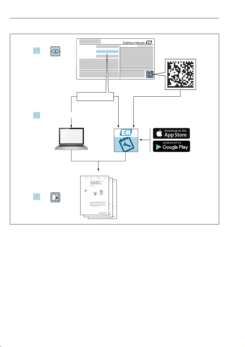
These Brief Operating Instructions are the Transmitter Brief Operating Instructions.
The "Sensor Brief Operating Instructions" are available via:
• Internet: www.endress.com/deviceviewer
• Smart phone/tablet: Endress+Hauser Operations App
Detailed information about the device can be found in the Operating Instructions and the
other documentation:
• Internet: www.endress.com/deviceviewer
• Smart phone/tablet: Endress+Hauser Operations App
Endress+Hauser 3

Table of contents Proline 300 EtherNet/IP
Table of contents
1 Document information ............................................................ 5
1.1 Symbols used ......................................................................... 5
2 Basic safety instructions .......................................................... 7
2.1 Requirements for the personnel ............................................................7
2.2 Designated use ........................................................................ 7
2.3 Workplace safety ...................................................................... 8
2.4 Operational safety ......................................................................8
2.5 Product safety .........................................................................9
2.6 IT security ............................................................................9
2.7 Device-specific IT security ................................................................ 9
3 Product description .............................................................. 10
4 Installation ...................................................................... 11
4.1 Turning the transmitter housing .......................................................... 11
4.2 Turning the display module .............................................................. 12
4.3 Cover locking ........................................................................ 13
4.4 Transmitter post-installation check ........................................................ 13
5 Electrical connection ............................................................ 14
5.1 Connection conditions .................................................................. 14
5.2 Connecting the measuring device ......................................................... 17
5.3 Hardware settings ..................................................................... 25
5.4 Ensuring potential equalization ........................................................... 26
5.5 Ensuring the degree of protection ......................................................... 26
5.6 Post-connection check .................................................................. 27
6 Operation options ............................................................... 28
6.1 Overview of operation options ............................................................ 28
6.2 Structure and function of the operating menu ................................................ 29
6.3 Access to the operating menu via the local display ............................................. 30
6.4 Access to the operating menu via the operating tool ............................................ 33
6.5 Access to the operating menu via the Web server .............................................. 33
7 System integration .............................................................. 33
8 Commissioning .................................................................. 33
8.1 Function check ....................................................................... 33
8.2 Setting the operating language ........................................................... 34
8.3 Configuring the measuring device ......................................................... 34
8.4 Protecting settings from unauthorized access ................................................. 35
9 Diagnostic information .......................................................... 36
4 Endress+Hauser
Proline 300 EtherNet/IP Document information
DANGER
WARNING
CAUTION
NOTICE
A
1.
1 Document information
1.1 Symbols used
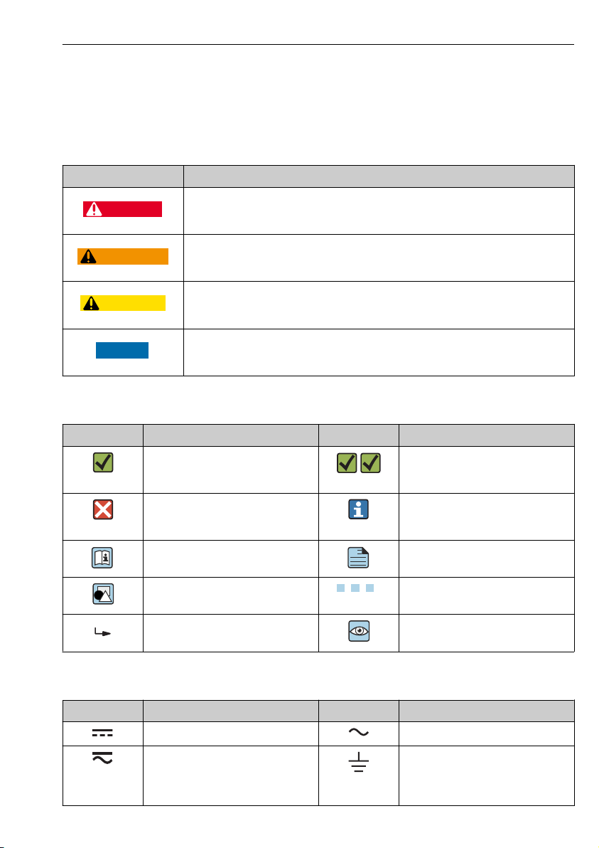
1.1.1 Safety symbols
Symbol Meaning
DANGER!
This symbol alerts you to a dangerous situation. Failure to avoid this situation will result in
serious or fatal injury.
WARNING!
This symbol alerts you to a dangerous situation. Failure to avoid this situation can result in
serious or fatal injury.
CAUTION!
This symbol alerts you to a dangerous situation. Failure to avoid this situation can result in
minor or medium injury.
NOTE!
This symbol contains information on procedures and other facts which do not result in
personal injury.
1.1.2 Symbols for certain types of information
Symbol Meaning Symbol Meaning
Permitted
Procedures, processes or actions that
are permitted.
Forbidden
Procedures, processes or actions that
are forbidden.
Reference to documentation
Preferred
Procedures, processes or actions that
are preferred.
Tip
Indicates additional information.
Reference to page
Reference to graphic
Result of a step Visual inspection
, 2., 3.… Series of steps
1.1.3 Electrical symbols
Symbol Meaning Symbol Meaning
Direct current Alternating current
Direct current and alternating current Ground connection
Endress+Hauser 5
A grounded terminal which, as far as
the operator is concerned, is grounded
via a grounding system.
Document information Proline 300 EtherNet/IP
1.
-
.
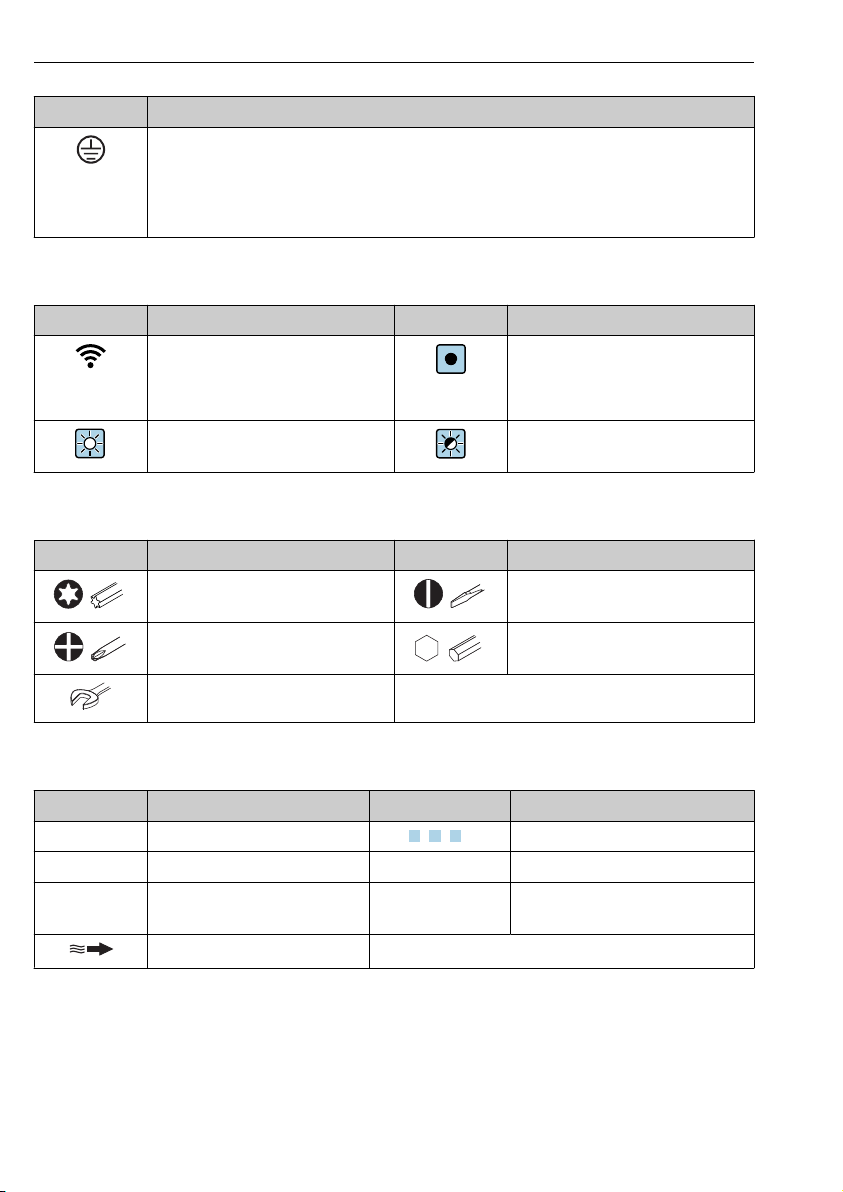
Symbol Meaning
Protective Earth (PE)
A terminal which must be connected to ground prior to establishing any other connections.
The ground terminals are situated inside and outside the device:
• Inner ground terminal: Connects the protectiv earth to the mains supply.
• Outer ground terminal: Connects the device to the plant grounding system.
1.1.4 Communication symbols
Symbol Meaning Symbol Meaning
Wireless Local Area Network
(WLAN)
Communication via a wireless, local
network.
LED
Light emitting diode is on.
LED
Light emitting diode is off.
LED
Light emitting diode is flashing.
1.1.5 Tool symbols
Symbol Meaning Symbol Meaning
Torx screwdriver Flat blade screwdriver
Cross-head screwdriver Allen key
Open-ended wrench
1.1.6 Symbols in graphics
Symbol Meaning Symbol Meaning
1, 2, 3,... Item numbers
A, B, C, ... Views A-A, B-B, C-C, ... Sections
Hazardous area
Flow direction
6 Endress+Hauser
, 2., 3.… Series of steps
Safe area (non-hazardous area)

Proline 300 EtherNet/IP Basic safety instructions
2 Basic safety instructions
2.1 Requirements for the personnel
The personnel must fulfill the following requirements for its tasks:
Trained, qualified specialists must have a relevant qualification for this specific function
‣
and task.
Are authorized by the plant owner/operator.
‣
Are familiar with federal/national regulations.
‣
Before starting work, read and understand the instructions in the manual and
‣
supplementary documentation as well as the certificates (depending on the application).
Follow instructions and comply with basic conditions.
‣
2.2 Designated use
Application and media
• The measuring device described in these Brief Operating Instructions is intended only for
flow measurement of liquids and gases.
• The measuring device described in these Brief Operating Instructions is intended only for
flow measurement of liquids.
Depending on the version ordered, the measuring device can also measure potentially
explosive, flammable, poisonous and oxidizing media.
Measuring devices for use in hazardous areas, in hygienic applications or where there is an
increased risk due to process pressure, are labeled accordingly on the nameplate.
To ensure that the measuring device remains in proper condition for the operation time:
Keep within the specified pressure and temperature range.
‣
Only use the measuring device in full compliance with the data on the nameplate and the
‣
general conditions listed in the Operating Instructions and supplementary documentation.
Based on the nameplate, check whether the ordered device is permitted for the intended
‣
use in the hazardous area (e.g. explosion protection, pressure vessel safety).
Use the measuring device only for media to which the process-wetted materials are
‣
sufficiently resistant.
If the ambient temperature of the measuring device is outside the atmospheric
‣
temperature, it is absolutely essential to comply with the relevant basic conditions as
specified in the device documentation.
Protect the measuring device permanently against corrosion from environmental
‣
influences.
Incorrect use
Non-designated use can compromise safety. The manufacturer is not liable for damage caused
by improper or non-designated use.
WARNING
L
Danger of breakage due to corrosive or abrasive fluids and ambient conditions!
Verify the compatibility of the process fluid with the sensor material.
‣
Ensure the resistance of all fluid-wetted materials in the process.
‣
Keep within the specified pressure and temperature range.
‣
Endress+Hauser 7

Basic safety instructions Proline 300 EtherNet/IP
NOTICE
Verification for borderline cases:
For special fluids and fluids for cleaning, Endress+Hauser is glad to provide assistance in
‣
verifying the corrosion resistance of fluid-wetted materials, but does not accept any
warranty or liability as minute changes in the temperature, concentration or level of
contamination in the process can alter the corrosion resistance properties.
Residual risks
WARNING
L
The electronics and the medium may cause the surfaces to heat up. This presents a burn
hazard!
For elevated fluid temperatures, ensure protection against contact to prevent burns.
‣
Only applies for Proline Promass A, E, F, O, X and Cubemass C
WARNING
L
Danger of housing breaking due to measuring tube breakage!
If a measuring tube ruptures, the pressure inside the sensor housing will rise according to the
operating process pressure.
Use a rupture disk.
‣
WARNING
L
Danger from medium escaping!
For device versions with a rupture disk: medium escaping under pressure can cause injury or
material damage.
Take precautions to prevent injury and material damage if the rupture disk is actuated.
‣
2.3 Workplace safety
For work on and with the device:
Wear the required personal protective equipment according to federal/national
‣
regulations.
For welding work on the piping:
Do not ground the welding unit via the measuring device.
‣
If working on and with the device with wet hands:
Due to the increased risk of electric shock, gloves must be worn.
‣
2.4 Operational safety
Risk of injury.
Operate the device in proper technical condition and fail-safe condition only.
‣
The operator is responsible for interference-free operation of the device.
‣
8 Endress+Hauser

Proline 300 EtherNet/IP Basic safety instructions
2.5 Product safety
This measuring device is designed in accordance with good engineering practice to meet stateof-the-art safety requirements, has been tested, and left the factory in a condition in which it
is safe to operate.
It meets general safety standards and legal requirements. It also complies with the EU
directives listed in the device-specific EU Declaration of Conformity. Endress+Hauser confirms
this by affixing the CE mark to the device.
2.6 IT security
Our warranty is valid only if the device is installed and used as described in the Operating
Instructions. The device is equipped with security mechanisms to protect it against any
inadvertent changes to the settings.
IT security measures, which provide additional protection for the device and associated data
transfer, must be implemented by the operators themselves in line with their security
standards.
2.7 Device-specific IT security
The device offers a range of specific functions to support protective measures on the operator's
side. These functions can be configured by the user and guarantee greater in-operation safety
if used correctly.
For detailed information on device-specific IT security, see the Operating Instructions for
the device.
2.7.1 Access via service interface (CDI-RJ45)
The device can be connected to a network via the service interface (CDI-RJ45). Device-specific
functions guarantee the secure operation of the device in a network.
The use of relevant industrial standards and guidelines that have been defined by national
and international safety committees, such as IEC/ISA62443 or the IEEE, is recommended.
This includes organizational security measures such as the assignment of access authorization
as well as technical measures such as network segmentation.
The device can be integrated in a ring topology. The device is integrated via the terminal
connection for signal transmission (output 1) and the connection to the service interface
(CDI-RJ45) .
Endress+Hauser 9
Product description Proline 300 EtherNet/IP
5
4
Nicht unter
Spannung öffnen
Do not open when
energized
Ne pas ouvrir
sous tension
Power
I/O
N
i
c
h
t
u
n
t
e
r
a
r
e
ö
f
f
n
e
n
D
i
s
p
l
a
y
+
E
ESC
–
1
2
3
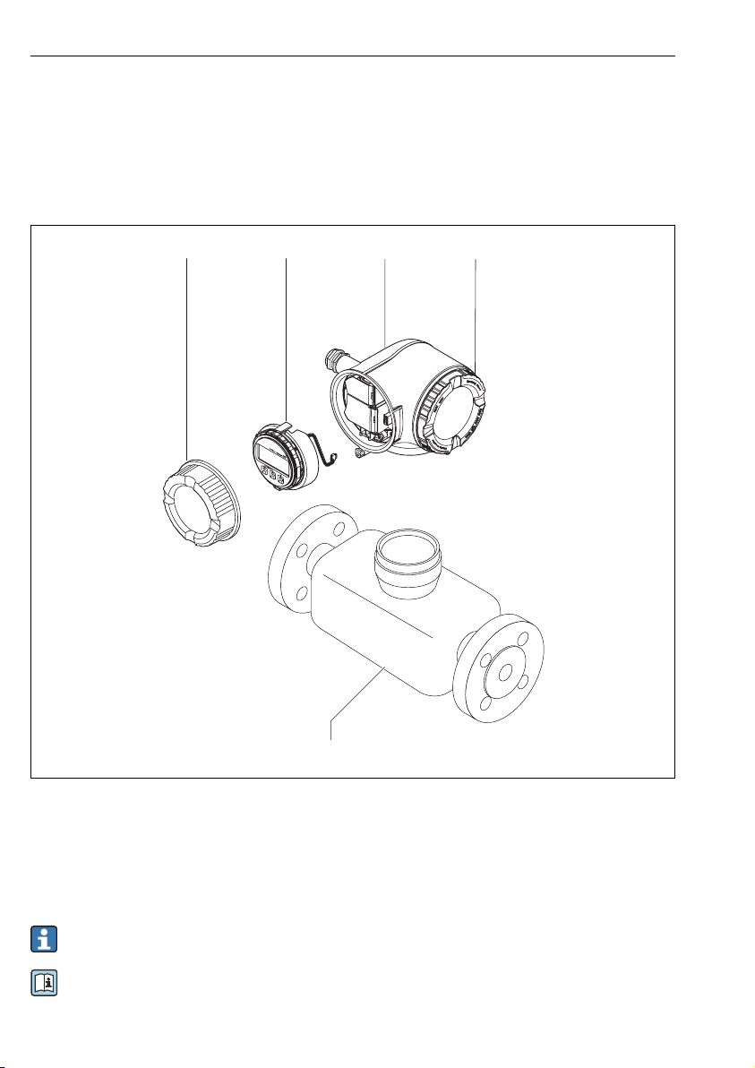
3 Product description
The device consists of a Proline 300 transmitter and a Proline Promass or Cubemass
Coriolis sensor.
The device is available as a compact version:
The transmitter and sensor form a mechanical unit.
A0029586
1 Connection compartment cover
2 Display module
3 Transmitter housing
4 Electronics compartment cover
5 Sensor
Use of the device with the remote display and operating module DKX001 → 24.
For detailed information on the product description, see the Operating Instructions for
the device
10 Endress+Hauser
Proline 300 EtherNet/IP Installation
N
i
c
h
t
u
n
t
e
r
a
r
e
ö
f
f
n
e
n
+
E
ESC
–
1.
2.
N
i
c
h
t
u
n
t
e
r
a
r
e
ö
f
f
n
e
n
+
E
ESC
–
3.
3 mm 4 mm
4.
4 Installation
For detailed information about mounting the sensor, see the Sensor Brief Operating
Instructions → 3
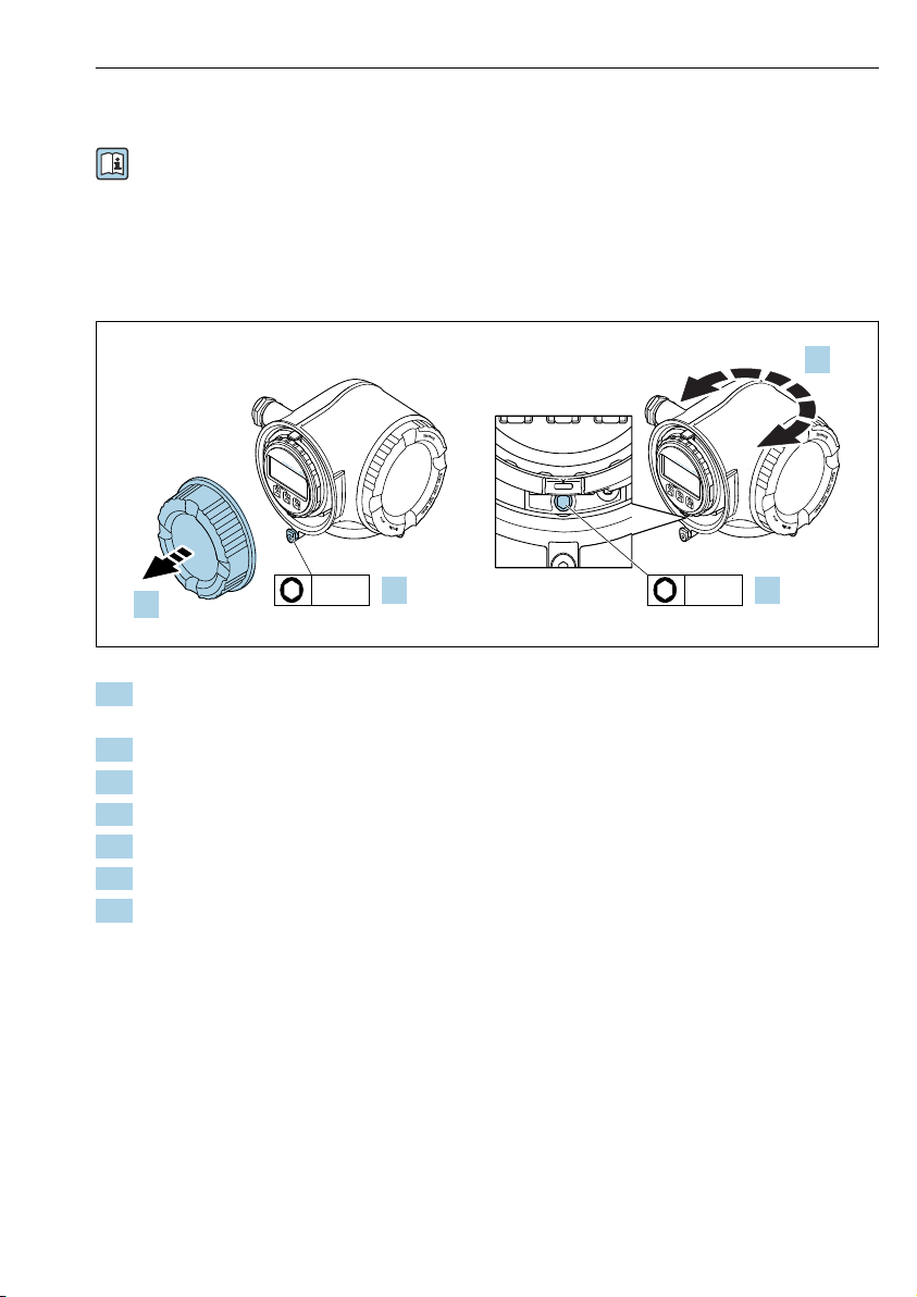
4.1 Turning the transmitter housing
To provide easier access to the connection compartment or display module, the transmitter
housing can be turned.
A0029993
1. Depending on the device version: Loosen the securing clamp of the connection
compartment cover.
2. Unscrew the connection compartment cover.
3. Release the fixing screw.
4. Turn the housing to the desired position.
5. Firmly tighten the securing screw.
6. Screw on the connection compartment cover
7. Depending on the device version: Attach the securing clamp of the connection
compartment cover.
Endress+Hauser 11
Installation Proline 300 EtherNet/IP
N
i
c
h
t
u
n
t
e
r
a
r
e
ö
f
f
n
e
n
+
E
ESC
–
1.
2.
N
i
c
h
t
u
n
t
e
r
a
r
e
ö
f
f
n
e
n
+
E
ESC
–
3.
3 mm
+
E
ESC
–
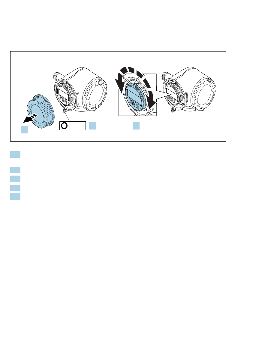
4.2 Turning the display module
The display module can be turned to optimize display readability and operability.
A0030035
1. Depending on the device version: Loosen the securing clamp of the connection
compartment cover.
2. Unscrew the connection compartment cover.
3. Turn the display module to the desired position: max. 8 × 45° in each direction.
4. Screw on the connection compartment cover.
5. Depending on the device version: Attach the securing clamp of the connection
compartment cover.
12 Endress+Hauser
 Loading...