

Endress+Hauser PMP51, PMC51 Specifications

TI00436P/00/EN/26.17
71375538
Products
Solutions Services
Technical Information
Cerabar M
PMC51, PMP51, PMP55
Process pressure measurement
Pressure transmitter with ceramic and
metal sensors
Application
The device is used for the following measuring tasks:
• Absolute pressure and gauge pressure measurement in gases, steams or liquids in
all areas of process engineering and process measurement technology
• Level, volume or mass measurement in liquids
• High process temperature
– without diaphragm seals up to 130 °C (266 °F), for a maximum of 60 minutes
150 °C (302 °F)
– with diaphragm seals up to 400 °C (752 °F)
• High pressure up to 400 bar (6 000 psi)
• International usage thanks to a wide range of approvals
Your benefits
• Very good reproducibility and long-term stability
• High reference accuracy up to ±0.15 %
as PLATINUM version: ±0.075 %
• Turn down up to 100:1
• Uniform platform for differential pressure, hydrostatics and pressure (Deltabar M
– Deltapilot M – Cerabar M)
• Simple, fast commissioning through a user interface designed for real-world
applications
• Used for process pressure monitoring up to SIL2, certified to IEC 61508 Edition 2.0
and IEC 61511 by TÜV NORD
• The patented TempC membrane for the diaphragm seal reduces measured errors
caused by environmental and process temperature influences to a minimum
• ASME-BPE-compliant device versions

Table of contents
Cerabar M PMC51, PMP51, PMP55
Document information ....................... 5
Document function ............................ 5
Symbols used ................................ 5
Documentation ............................... 6
Terms and abbreviations ........................ 7
Turn down calculation .......................... 8
Function and system design ................... 9
Device selection .............................. 9
Measuring principle ........................... 11
Level measurement (level, volume and mass) .......... 12
Electrical differential pressure measurement with gauge
pressure sensors ............................. 12
Communication protocol ........................ 13
Input .................................... 14
Measured variable ............................ 14
Measuring range ............................. 14
Output .................................. 16
Output signal ............................... 16
Signal range 4 to 20 mA ........................ 16
Signal on alarm .............................. 16
Load - 4 to 20 mA Analog 4...20 mA HART ........... 16
Resolution ................................. 17
Dead time, Time constant ....................... 17
Dynamic behavior current output (analog electronics) .... 17
Dynamic behavior current output (HART electronics) ..... 17
Dynamic behavior digital output (HART electronics) ..... 17
Dynamic behavior PROFIBUS PA .................. 17
Dynamic behavior FOUNDATION Fieldbus ............ 18
Damping .................................. 18
Firmware version ............................ 18
Protocol-specific data HART ..................... 19
Protocol-specific data PROFIBUS PA ................ 19
Protocol-specific data FOUNDATION Fieldbus .......... 20
Reference accuracy – PMC51 ..................... 28
Thermal change in the zero output and the output span –
PMC51 ................................... 28
Total performance – PMC51 ..................... 29
Long-term stability ........................... 29
Total Error - PMC51 .......................... 30
Warm-up period ............................. 30
Performance characteristics of the metallic
process isolating diaphragm .................. 31
Reference operating conditions ................... 31
Uncertainty of measurement for small absolute pressure
ranges .................................... 31
Performance Characteristics Conformance ............ 31
Influence of orientation ........................ 31
Reference accuracy – PMP51 , PMP55 .............. 32
Thermal change in the zero output and the output span –
PMP51 and PMP55 ........................... 33
Total Performance – PMP51 ..................... 34
Long-term stability ........................... 34
Total Error - PMP51 .......................... 35
Warm-up period ............................. 35
Installation ............................... 36
General installation instructions ................... 36
Measuring arrangement for devices without diaphragm
seal – PMC51, PMP51 ......................... 36
Measuring arrangement for devices with diaphragm seal –
PMP55 ................................... 36
Wall and pipe mounting, transmitter (optional) ........ 37
Wall and pipe-mounting manifold (optional) .......... 37
"Separate housing" version ....................... 38
Oxygen applications ........................... 39
PWIS cleaning .............................. 39
Ultrapure gas applications (PMC51 und PMP51) ........ 39
Applications with hydrogen ...................... 39
Power supply ............................. 22
Terminal assignment .......................... 22
Supply voltage .............................. 22
Current consumption .......................... 23
Electrical connection .......................... 23
Terminals ................................. 23
Cable entry ................................. 23
Device plug connectors ......................... 24
Cable specification ............................ 25
Start-up current ............................. 26
Residual ripple .............................. 26
Influence of power supply ....................... 26
Overvoltage protection (optional) .................. 26
Environment .............................. 40
Ambient temperature range ..................... 40
Storage temperature range ...................... 40
Climate class ............................... 40
Degree of protection .......................... 40
Vibration resistance ........................... 40
Electromagnetic compatibility .................... 41
Process .................................. 42
Process temperature range PMC51 ................. 42
Process temperature limits ...................... 42
Process temperature limits of flexible capillary armoring:
PMP55 ................................... 44
Pressure specifications ......................... 44
Performance characteristics of the ceramic
process isolating diaphragm .................. 27
Reference operating conditions ................... 27
Influence of orientation ........................ 27
Uncertainty of measurement for small absolute pressure
ranges .................................... 27
Mechanical construction .................... 45
Device height ............................... 45
F31 housing, aluminum ........................ 45
F15 housing, stainless steel (hygienic) .............. 46
2 Endress+Hauser

Cerabar M PMC51, PMP51, PMP55
PMC51: process connections with internal process
isolating diaphragm ........................... 47
PMC51: process connections with internal process
isolating diaphragm ........................... 49
PMC51: process connections with internal process
isolating diaphragm - height H ................... 49
PMC51: process connections with flush-mounted process
isolating diaphragm ........................... 50
PMC51: process connections with flush-mounted process
isolating diaphragm ........................... 51
PMC51: process connections with flush-mounted process
isolating diaphragm - height H ................... 51
PMC51: process connections with flush-mounted process
isolating diaphragm ........................... 52
PMC51: process connections with flush-mounted process
isolating diaphragm - height H ................... 54
PMC51: hygienic process connections with flushmounted
process isolating diaphragm ..................... 55
PMP51: process connections with internal process
isolating diaphragm ........................... 60
PMP51: process connections with internal process
isolating diaphragm ........................... 61
PMP51: process connections with flush-mounted process
isolating diaphragm ........................... 62
ANSI threaded connection ...................... 64
PMP51: process connections with flush-mounted process
isolating diaphragm ........................... 65
PMP51: process connections with flush-mounted process
isolating diaphragm ........................... 66
PMP51: hygienic process connections with flushmounted
process isolating diaphragm ..................... 67
Valve manifold DA63M- (optional) ................. 71
PMP51: process connections ..................... 72
PMP55 basic device - examples ................... 73
PMP55: process connections with flush-mounted process
isolating diaphragm ........................... 74
PMP55: process connections with flush-mounted process
isolating diaphragm ........................... 75
PMP55: process connections with flush-mounted process
isolating diaphragm ........................... 76
PMP55: process connections with flush-mounted process
isolating diaphragm ........................... 77
PMP55: hygienic process connections with flushmounted
process isolating diaphragm ..................... 78
PMP55: hygienic process connections with flushmounted
process isolating diaphragm ..................... 79
PMP55: process connections with flush-mounted process
isolating diaphragm ........................... 85
PMP55: process connections with flush-mounted process
isolating diaphragm ........................... 87
PMP55 process connections ..................... 90
Wall and pipe mounting with "Separate housing" version ... 93
Reduction in installation height ................... 94
Weight ................................... 94
Materials not in contact with process ............... 95
Materials in contact with the process ............... 98
Seals ..................................... 99
Fill fluid ................................... 99
Operability .............................. 101
Operating concept ........................... 101
Local operation ............................. 101
Operating languages ......................... 104
Remote operation ........................... 105
System integration (Except analog electronics) ........ 106
Planning instructions for diaphragm seal
systems ................................. 107
Applications ............................... 107
Function and design .......................... 108
Diaphragm seal filling oils ...................... 109
Operating temperature range .................... 109
Cleaning instructions ......................... 110
Installation instructions ....................... 110
Vacuum applications ......................... 111
Certificates and approvals .................. 113
CE mark .................................. 113
RoHS .................................... 113
RCM-Tick marking ........................... 113
Ex approvals ............................... 113
EAC conformity ............................. 113
Suitable for hygiene applications ................. 113
Certificate of Compliance ASME BPE 2012 ........... 114
Functional safety SIL ......................... 114
CRN approvals ............................. 114
Other standards and guidelines .................. 114
AD2000 .................................. 114
Pressure Equipment Directive 2014/68/EU (PED) ...... 114
Manufacturer declaration ...................... 115
Marine approval ............................ 116
Drinking water approval ....................... 116
Classification of process sealing between electrical
systems and (flammable or combustible) process fluids in
accordance with ANSI/ ISA 12.27.01 .............. 116
Inspection certificate ......................... 116
Calibration; unit ............................ 117
Calibration ................................ 117
Service ................................... 117
Ordering information ...................... 118
Scope of delivery ............................ 118
Measuring point (TAG) ........................ 118
Configuration data sheet (HART, PROFIBUS PA,
FOUNDATION Fieldbus electronics) ............... 118
Configuration data sheet (Analog electronics) ......... 121
Additional documentation .................. 122
Field of Activities ............................ 122
Technical Information ........................ 122
Special Documentation ........................ 122
Operating Instructions ........................ 122
Brief operating instruction ..................... 122
Functional safety manual (SIL) ................... 122
Safety Instructions ........................... 122
Accessories .............................. 125
Manifolds ................................ 125
Additional mechanical accessories ................ 125
Welding necks and Weld-in tool flanges ............ 125
Mounting bracket for wall and pipe mounting ......... 126
M12 connector ............................. 126
Registered trademarks ..................... 126
HART® .................................. 126
PROFIBUS® ............................... 126
Endress+Hauser 3

FOUNDATIONTMFieldbus ...................... 126
Cerabar M PMC51, PMP51, PMP55
4 Endress+Hauser

Cerabar M PMC51, PMP51, PMP55
DANGER
WARNING
CAUTION
NOTICE
A
,…,
1.
2.
3.
Document information
Document function
The document contains all the technical data on the device and provides an overview of the
accessories and other products that can be ordered for the device.
Symbols used Safety symbols
Symbol Meaning
Electrical symbols
Symbol Meaning Symbol Meaning
DANGER!
This symbol alerts you to a dangerous situation. Failure to avoid this situation will result in
seriousor fatal injury.
WARNING!
This symbol alerts you to a dangerous situation. Failure to avoid this situation can result in
seriousor fatal injury.
CAUTION!
This symbol alerts you to a dangerous situation. Failure to avoid this situation can result in
minoror medium injury.
NOTICE!
This symbol contains information on procedures and other facts which do not result in
personalinjury.
Protective ground connection
A terminal which must be connected
to ground prior to establishing any
other connections.
Ground connection
A grounded terminal which, as far as
the operator is concerned, is
grounded via a grounding system.
Symbols for certain types of information
Symbol Meaning
Permitted
Procedures, processes or actions that are permitted.
Preferred
Procedures, processes or actions that are preferred.
Forbidden
Procedures, processes or actions that are forbidden.
Tip
Indicates additional information.
Reference to documentation
Reference to page
Reference to graphic
Visual inspection
Symbols in graphics
Symbol Meaning
1, 2, 3 ... Item numbers
Series of steps
Endress+Hauser 5

Symbol Meaning
A, B, C, ... Views
A-A, B-B, C-C, ... Sections
Cerabar M PMC51, PMP51, PMP55
Documentation
See chapter "Additional documentation" → 122
The document types listed are available:
In the Download Area of the Endress+Hauser Internet site: www.endress.com → Download
6 Endress+Hauser

Cerabar M PMC51, PMP51, PMP55
URL OPLMWP
LRL
0
p
LRV
URV
1
2
3
4
Terms and abbreviations
A0029505
Item Term/abbreviation Explanation
1 OPL The OPL (over pressure limit = sensor overload limit) for the measuring device depends on the lowest-rated element,
with regard to pressure, of the selected components, i.e. the process connection has to be taken into consideration in
addition to the measuring cell. Also observe pressure-temperature dependency. For the relevant standards and
additional notes see the → 44 section.
The OPL may only be applied for a limited period of time.
2 MWP The MWP (maximum working pressure) for the sensors depends on the lowest-rated element, with regard to
pressure, of the selected components, i.e. the process connection has to be taken into consideration in addition to the
measuring cell. Also observe pressure-temperature dependency. For the relevant standards and additional notes see
the → 44 section.
The MWP may be applied at the device for an unlimited period.
The MWP can also be found on the nameplate.
3 Maximum sensor
measuring range
4 Calibrated/adjusted
span
p - Pressure
- LRL Lower range limit
- URL Upper range limit
- LRV Lower range value
- URV Upper range value
- TD (Turn down) Turn down
Span between LRL and URL
This sensor measuring range is equivalent to the maximum calibratable/adjustable span.
Span between LRV and URV
Factory setting: 0 to URL
Other calibrated spans can be ordered as customized spans.
Example - see the following section.
Endress+Hauser 7

Turn down calculation
LRV
URLURV
LRL
1 = 2
3
1 Calibrated/adjusted span
2 Zero point-based span
3 URL sensor
Example
• Sensor:10 bar (150 psi)
• Upper range value (URL) = 10 bar (150 psi)
Turn down (TD):
Cerabar M PMC51, PMP51, PMP55
A0029545
• Calibrated/adjusted span: 0 to 5 bar (0 to 75 psi)
• Lower range value (LRV) = 0 bar (0 psi)
• Upper range value (URV) = 5 bar (75 psi)
TD =
URL
|URV - LRV|
10 bar (150 psi)
TD =
|5 bar (75 psi) - 0 bar (0 psi)|
In this example, the TD is 2:1.
This span is based on the zero point.
= 2
8 Endress+Hauser

Cerabar M PMC51, PMP51, PMP55
Function and system design
Device selection
PMC51 with capacitive measuring cell and ceramic process isolating diaphragm (Ceraphire®)
PMP51 with piezoresistive measuring cell and metallic welded process isolating diaphragm
A0023673
A0023675
PMP55 with diaphragm seal
Field of application
• Gauge pressure and absolute pressure
• Level
Process connections
PMC51:
• Thread
• EN flanges DN 25 – DN 80
• ANSI flanges 1" – 4"
• JIS flanges 50 A – 100 A
• Flush-mounted hygienic connections
PMP51:
• Thread
• EN flanges DN 25 – DN 80
• ANSI flanges 1" – 4"
• Prepared for diaphragm seal mount
• Flush-mounted hygienic connections
PMP55:
Wide range of diaphragm seals
Measuring ranges
• PMC51: From –100/0 to 100 mbar (–1.5/0 to 1.5 psi) to –1/0 to 40 bar (–15/0 to 600 psi)
• PMP51: From –400/0 to 400 mbar (–6/0 to 6 psi) to –1/0 to 400 bar (–15/0 to 6000 psi)
• PMP55: From –400/0 to 400 mbar (–6/0 to 6 psi) to –1/0 to 400 bar (–15/0 to 6000 psi)
A0023676
Endress+Hauser 9

Cerabar M PMC51, PMP51, PMP55
OPL
• PMC51: max. 60 bar (900 psi)
• PMP51: max. 600 bar (9 000 psi)
• PMP55: max. 600 bar (9 000 psi)
Process temperature range
• PMC51: –20 to +130 °C (–4 to +266 °F)
For a maximum of 60 minutes: +150 °C (+302 °F)
• PMP51: –40 to +130 °C (–40 to +266 °F)
For a maximum of 60 minutes: +150 °C (+302 °F)
• PMP55: –70 to +400 °C (–94 to +752 °F)
(depending on the filling oil)
Ambient temperature range
• Without LCD: –40 to +85 °C (–40 to +185 °F)
• With LCD display: –20 to +70 °C (–4 to +158 °F)
(extended temperature application range–40 to +85 °C (–40 to +185 °F) with limitations in optical
properties, such as display speed and contrast)
• Separate housing:–20 to +60 °C (–4 to +140 °F)
• PMP55: Diaphragm seal systems depending on the version
Reference accuracy
• PMC51: Up to ±0.15% of the set span
PLATINUM-Version: up to ±0.075% of the set span
• PMP51: Up to ±0.15% of the set span
PLATINUM-Version: up to ±0.075% of the set span
• PMP55: Up to ±0.15% of the set span
Supply voltage
• 11.5 to 45 V DC (versions with plug-in connection 35 V DC)
• For intrinsically safe device versions: 11.5 to 30 V DC
Output
4 to 20 mA, 4 to 20 mA with superimposed HART protocol, PROFIBUS PA or FOUNDATION Fieldbus
Options
• Inspection certificate 2.2 or 3.1 or other certificates
• 3Aapproval and EHEDG approval
• Specific firmware versions
• Initial device settings
• Separate housing
• Broad range of accessories
• NACE-compliant materials
Specialties
• PMC51:
– Metal-free measurement with PVDF connection
– Special cleaning of the transmitter to remove paint-wetting substances, for use in paint shops
• PMP51:
– Process connections with minimum oil volume
– Gas-tight, elastomer-free
• PMP55:
– Wide range of diaphragm seals
– For extreme medium temperatures
– Process connections with minimum oil volume
– Completely welded versions
10 Endress+Hauser

Cerabar M PMC51, PMP51, PMP55
1
2
3
4
p
p
1
3
4
2
Measuring principle
Ceramic process isolating diaphragm used in PMC51 (Ceraphire®)
A0020465
1 Air pressure (gauge pressure sensors)
2 Ceramic substrate
3 Electrodes
4 Ceramic process isolating diaphragm
The ceramic sensor is a dry sensor, i.e. the process pressure acts directly on the robust ceramic
process isolating diaphragm and deflects it. A pressure-dependent change in capacitance is
measured at the electrodes of the ceramic substrate and the process isolating diaphragm. The
measuring range is determined by the thickness of the ceramic process isolating diaphragm.
Advantages:
• Guaranteed overload resistance up to 40 times the nominal pressure
• Thanks to ultrapure 99.9% ceramic (Ceraphire®, see also "www.endress.com/ceraphire")
– extremely high chemical stability, comparable with Alloy C
– high mechanical stability
• Can be used in absolute vacuum
Metallic process isolating diaphragm used in PMP51 and PMP55
A0016448
1 Silicon measuring element, substrate
2 Wheatstone bridge
3 Channel with fill fluid
4 Metallic process isolating diaphragm
PMP51
The operating pressure deflects the process isolating diaphragm and a fill fluid transfers the pressure
to a resistance bridge (semiconductor technology). The pressure-dependent change in the bridge
output voltage is measured and evaluated.
Advantages:
• Can be used for process pressure up to 400 bar (6 000 psi)
• High long-term stability
• Guaranteed overload resistance up to 4 times the nominal pressure
• Significantly less thermal effect compared to diaphragm seal systems
Endress+Hauser 11

Level measurement (level,
h =
p
ρ g
h
Fieldgate
FXA520
FXN 520
FXN 520
Multidrop-Connector
FXN520
Cerabar M
Á
11
2
volume and mass)
Cerabar M PMC51, PMP51, PMP55
PMP55
The operating pressure acts on the process isolating diaphragm of the diaphragm seal and is
transferred to the process isolating diaphragm of the sensor by a diaphragm seal fill fluid. The
process isolating diaphragm is deflected and a fill fluid transfers the pressure to a resistance bridge.
The pressure-dependent change in the bridge output voltage is measured and evaluated.
Advantages:
• Depending on the version, can be used for process pressure up to 400 bar (6 000 psi) and
simultaneous extreme process temperatures
• High long-term stability
• Guaranteed overload resistance up to 4 times the nominal pressure
Electrical differential pressure measurement with gauge pressure sensors
A0023678
h Height (level)
p Pressure
ρ Density of the medium
g Gravitation constant
Your benefits
• Choice of different level measuring modes in the device software
• Volume and mass measurements in any tank shapes by means of a freely programmable
characteristic curve
• Choice of diverse level units
• Has a wide range of uses, even in the following cases:
– in the event of foam formation
– in tanks with agitators of screen fittings
– in the event of liquid gases
1 Shut-off valves
2 e.g. filter
In the example given, two Cerabar M devices (each with a gauge pressure sensor) are
interconnected. The pressure difference can thus be measured using two independent Cerabar M
devices.
12 Endress+Hauser
A0023680

Cerabar M PMC51, PMP51, PMP55
L
Risk of explosion!
‣
WARNING
If using intrinsically safe devices, strict compliance with the rules for interconnecting intrinsically
safe circuits as stipulated in IEC60079-14 (proof of intrinsic safety) is mandatory.
Communication protocol
• 4 to 20 mA without communication protocol (analog electronics)
• 4 to 20 mA with HART communication protocol
• PROFIBUS PA
– The Endress+Hauser devices meet the requirements of the FISCO model.
– Due to a low current consumption of 11 mA ± 1 mA, the following number of devices can be
operated on one bus segment if installing as per FISCO: up to 8 devices for Ex ia, CSA IS and FM
IS applications or up to 31 devices for all other applications e.g. in non-hazardous areas, Ex nA
etc. Further information on PROFIBUS PA can be found in Operating Instructions BA00034S
"PROFIBUS DP/PA: Guidelines for planning and commissioning" and in the PNO Guideline.
• FOUNDATION Fieldbus
– The Endress+Hauser devices meet the requirements of the FISCO model.
– Due to a low current consumption of 16 mA ± 1 mA, the following number of devices can be
operated on one bus segment if installing as per FISCO: up to 6 devices for Ex ia, CSA IS and FM
IS applications or up to 22 devices for all other applications e.g. in non-hazardous areas, Ex nA
etc. Further information on FOUNDATION Fieldbus, such as requirements for bus system
components, can be found in Operating Instructions BA00013S "FOUNDATION Fieldbus
Overview".
Endress+Hauser 13

Cerabar M PMC51, PMP51, PMP55
Input
Measured variable Measured process variables
• Analog electronics: Absolute pressure and gauge pressure
• HART, PROFIBUS PA, FOUNDATION Fieldbus: Absolute pressure and gauge pressure, from which
level (level, volume or mass) is derived
Measuring range PMC51 – with ceramic process isolating diaphragm (Ceraphire®) for gauge pressure
Sensor Maximum sensor measuring range Smallest calibratable
lower (LRL) upper (URL)
measuring span (preset at
the factory)
1)
[bar (psi)] [bar (psi)] [bar (psi)] [bar (psi)] [bar (psi)] [bar
MWP OPL Vacuum
resistance
abs
(psi
abs
)]
100 mbar (1.5 psi) –0.1 (–1.5) +0.1 (+1.5) 0.01 (0.15) 2.7 (40.5) 4 (60) 0.7 (10.5) 1C
250 mbar
–0.25 (–3.75) +0.25 (+3.75) 0.01 (0.15) 3.3 (49.5) 5 (75) 0.5 (7.5) 1E
(3.75 psi)
400 mbar (6 psi) –0.4 (–6) +0.4 (+6) 0.02 (0.3) 5.3 (79.5) 8 (120) 0 1F
1 bar (15 psi) –1 (–15) +1 (+15) 0.05 (1) 6.7 (100.5) 10 (150) 0 1H
2 bar (30 psi) –1 (–15) +2 (+30) 0.1 (1.5) 12 (180) 18 (270) 0 1K
4 bar (60 psi) –1 (–15) +4 (+60) 0.2 (3) 16.7 (250.5) 25 (375) 0 1M
10 bar (150 psi) –1 (–15) +10 (+150) 0.5 (7.5) 26.7 (400.5) 40 (600) 0 1P
40 bar (600 psi) –1 (–15) +40 (+600) 2 (30) 40 (600) 60 (900) 0 1S
1) Factory calibration turn down: Max 20:1, higher on request or configurable in the device.
2) Product Configurator, "Sensor range" ordering feature
PMC51 – with ceramic process isolating diaphragm (Ceraphire®) for absolute pressure
Sensor Maximum sensor measuring
range
lower (LRL) upper (URL)
100 mbar
[bar
abs
(psi
)]
abs
0 +0.1 (+1.5) 0.01 (0.15) 2.7 (40.5) 4 (60) 0 2C
[bar
abs
(psi
(1.5 psi)
250 mbar
0 +0.25 (+3.75) 0.01 (0.15) 3.3 (49.5) 5 (75) 0 2E
(3.75 psi)
400 mbar (6 psi) 0 +0.4 (+6) 0.02 (0.3) 5.3 (79.5) 8 (120) 0 2F
1 bar (15 psi) 0 +1 (+15) 0.05 (1) 6.7 (100.5) 10 (150) 0 2H
2 bar (30 psi) 0 +2 (+30) 0.1 (1.5) 12 (180) 18 (270) 0 2K
4 bar (60 psi) 0 +4 (+60) 0.2 (3) 16.7 (250.5) 25 (375) 0 2M
10 bar (150 psi) 0 +10 (+150) 0.5 (7.5) 26.7 (400.5) 40 (600) 0 2P
40 bar (600 psi) 0 +40 (+600) 2 (30) 40 (600) 60 (900) 0 2S
Smallest calibratable
measuring span (preset
at the factory)
)] [bar (psi)] [bar
abs
1)
MWP OPL Vacuum
resistance
(psi
abs
)] [bar
abs
abs
(psi
)] [bar
abs
abs
(psi
abs
)]
Option
Option
2)
2)
1) Factory calibration turn down: Max 20:1, higher on request or configurable in the device.
2) Product Configurator, "Sensor range" ordering feature
14 Endress+Hauser

Cerabar M PMC51, PMP51, PMP55
PMP51 and PMP55 – metallic process isolating diaphragm for gauge pressure
Sensor Maximum sensor measuring
range
lower (LRL) upper (URL) Silicone oil/
Smallest calibratable
measuring span (preset
at the factory)
1)
MWP OPL Vacuum resistance
2)
Option
Inert oil/
Synthetic oil
[bar (psi)] [bar (psi)] [bar (psi)] [bar (psi)] [bar (psi)] [bar
400 mbar (6 psi) –0.4 (–6) +0.4 (+6) 0.02 (0.3) 4 (60) 6 (90)
abs
(psi
abs
)]
1F
1 bar (15 psi) –1 (–15) +1 (+15) 0.05 (1) 6.7 (100) 10 (150) 1H
2 bar (30 psi) –1 (–15) +2 (+30) 0.1 (1.5) 13.3 (200) 20 (300) 1K
4 bar (60 psi) –1 (–15) +4 (+60) 0.2 (3) 18.7 (280.5) 28 (420) 1M
10 bar (150 psi) –1 (–15) +10 (+150) 0.5 (7.5) 26.7 (400.5) 40 (600) 1P
0.01/0.04/0.01
(0.15/0.6/0.15)
40 bar (600 psi) –1 (–15) +40 (+600) 2 (30) 100 (1500) 160 (2400) 1S
100 bar
–1 (–15) +100 (+1500) 5 (75) 100 (1500) 400 (6000) 1U
(1 500 psi)
400 bar
–1 (–15) +400 (+6000) 20 (300) 400 (6000) 600 (9000) 1W
(6 000 psi)
1) Factory calibration turn down: Max 20:1, higher on request or configurable in the device.
2) The vacuum resistance applies to the measuring cell at reference conditions. The pressure and temperature application limits of the selected
filling oil must also be observed for the PMP55. → 109.
3) Product Configurator, "Sensor range" ordering feature
3)
PMP51 and PMP55 – metallic process isolating diaphragm for absolute pressure
abs
2)
Option
)]
2F
Sensor Maximum sensor measuring
range
lower (LRL) lower (URL) Silicone oil/
Smallest calibratable
measuring span
(preset at the
1)
factory)
MWP OPL Vacuum resistance
Inert oil/
Synthetic oil
[bar
(psi
abs
abs
)]
[bar
abs
(psi
)] [bar (psi)] [bar
abs
(psi
abs
abs
[bar
)]
(psi
abs
abs
)]
[bar
abs
(psi
400 mbar (6 psi) 0 +0.4 (+6) 0.02 (0.3) 4 (60) 6 (90)
1 bar (15 psi) 0 +1 (+15) 0.05 (1) 6.7 (100) 10 (150) 2H
2 bar (30 psi) 0 +2 (+30) 0.1 (1.5) 13.3 (200) 20 (300) 2K
4 bar (60 psi) 0 +4 (+60) 0.2 (3) 18.7 (280.5) 28 (420) 2M
10 bar (150 psi) 0 +10 (+150) 0.5 (7.5) 26.7 (400.5) 40 (600) 2P
0.01/0.04/0.01
(0.15/0.6/0.15)
40 bar (600 psi) 0 +40 (+600) 2 (30) 100 (1500) 160 (2400) 2S
100 bar
0 +100 (+1500) 5 (75) 100 (1500) 400 (6000) 2U
(1 500 psi)
400 bar
0 +400 (+6000) 20 (300) 400 (6000) 600 (9000) 2W
(6 000 psi)
1) Factory calibration turn down: Max 20:1, higher on request or configurable in the device.
2) The vacuum resistance applies to the measuring cell at reference conditions. The pressure and temperature application limits of the selected
filling oil must also be observed for the PMP55. → 109.
3) Product Configurator, "Sensor range" ordering feature
3)
Endress+Hauser 15

Output
U – 11.5 V
23 mA
[ ]W
30
20
11.5
40 45
1239
1456
804
369
£
U
[V]
1
2
R
L
max
3
R
L
max
Cerabar M PMC51, PMP51, PMP55
Output signal
Signal range 4 to 20 mA
Signal on alarm
• 4 to 20 mA analog, 2-wire
• 4 to 20 mA with superimposed digital communication protocol HART 6.0, 2-wire
• Digital communication signal PROFIBUS PA (Profile 3.02)
• Digital communication signal FOUNDATION Fieldbus
Output Option
4 to 20mA 1
4 to 20mA HART 2
PROFIBUS PA 3
FOUNDATION Fieldbus 4
1) Product Configurator, "Output" ordering feature
4 to 20 mA Analog, 4 to 20 mA HART: 3.8 to 20.5 mA
As per NAMUR NE 43
• 4 to 20 mA Analog:
– Signal overshoot: > 20.5 mA
– Signal undershoot: < 3.8 mA
– Min Alarm (3.6 mA)
• 4 to 20 mA HART:
Options:
– Max. alarm: can be set from 21 to 23 mA (factory setting: 22 mA)
– Hold measured value: last measured value is held
– Min. alarm: 3.6 mA
• PROFIBUS PA: can be set in the Analog Input block
Options: Last Valid Out Value (factory setting), Fail-safe Value, Status Bad
• FOUNDATION Fieldbus: can be set in the Analog Input block
Options: Last Good Value, Fail-safe Value (factory setting), Wrong Value
1)
Load - 4 to 20 mA Analog
4...20 mA HART
1 Supply voltage 11.5 to 30 V DC for intrinsically safe device versions (not for analog)
2 Supply voltage 11.5 to 45 V DC (versions with plug-in connector 35 V DC) for other types of protection and
for uncertified device versions
3 R
U Supply voltage
Maximum load resistance
Lmax
When operating via a handheld terminal or via a PC with an operating program, a minimum
16 Endress+Hauser
communication resistance of 250 Ω must be taken into account.
A0023090

Cerabar M PMC51, PMP51, PMP55
I
63 %
100 %
t
t1t
2
90 %
t
3
Resolution
Dead time, Time constant
Dynamic behavior current output (analog electronics)
Dynamic behavior current output (HART electronics)
• Current output: 1 μA
• Display: can be set (factory setting: presentation of the maximum accuracy of the transmitter)
Presentation of the dead time and the time constant:
A0019786
Type Dead time (t1) [ms] Time constant T63 (= t2) [ms] Time constant T90 (= t3) [ms]
max. PMC51 60 40 50
max. PMP51 40 40 50
max. PMP55 PMP51 + influence of the diaphragm seal
Type Dead time (t1) [ms] Time constant T63 (= t2) [ms] Time constant T90 (= t3) [ms]
max. PMC51 50 85 200
max. PMP51 70 80 185
max. PMP55 PMP51 + influence of the diaphragm seal
Dynamic behavior digital output (HART electronics)
Type Dead time (t1) [ms] Dead time (t1) [ms] +
Time constant T63 (= t2) [ms]
min. PMC51 210 295 360
max. 1010 1095 1160
min. PMP51 210 285 345
max. 1010 1085 1145
max. PMP55 PMP51 + influence of the diaphragm seal
Dead time (t1) [ms] +
Time constant T90 (= t3) [ms]
Reading cycle
• Acyclic: max. 3/s, typical 1/s (depends on command # and number of preambles)
• Cyclic (Burst): max. 3/s, typical 2/s
The device commands the BURST MODE function for cyclic value transmission via the HART
communication protocol.
Cycle time (update time)
Cyclic (Burst): min. 300 ms
Response time
• Acyclic: min. 330 ms, typical 590 ms (depends on command # and number of preambles)
• Cyclic (Burst): min. 160 ms, typical 350 ms (depends on command # and number of preambles)
Dynamic behavior PROFIBUS PA
Type Dead time (t1) [ms] Dead time (t1) [ms] +
Time constant T63 (= t2) [ms]
min. PMC51 85 170 235
max. 1185 1270 1335
Dead time (t1) [ms] +
Time constant T90 (= t3) [ms]
Endress+Hauser 17

Cerabar M PMC51, PMP51, PMP55
Dynamic behavior FOUNDATION Fieldbus
Type Dead time (t1) [ms] Dead time (t1) [ms] +
Time constant T63 (= t2) [ms]
min. PMP51 85 160 220
max. 1185 1260 1320
max. PMP55 PMP51 + influence of the diaphragm seal
Dead time (t1) [ms] +
Time constant T90 (= t3) [ms]
Reading cycle (SPS)
• Acyclic: typical 25/s
• Cyclic: max. 30/s (dependent on the number and type of function blocks used in a closed-control
loop)
Cycle time (update time)
min. 100 ms
The cycle time in a bus segment in cyclic data communication depends on the number of devices, on
the segment coupler used and on the internal PLC cycle time.
Response time
• Acyclic: approx. 23 to 35 ms (depends on Min. Slave Interval)
• Cyclic: approx. 8 to 13 ms (depends on Min. Slave Interval)
Type Dead time (t1) [ms] Dead time (t1) [ms] +
Time constant T63 (= t2) [ms]
min. PMC51 95 180 245
max. 1095 1180 1245
min. PMP51 95 170 230
max. 1095 1170 1230
max. PMP55 PMP51 + influence of the diaphragm seal
Dead time (t1) [ms] +
Time constant T90 (= t3) [ms]
Damping
Firmware version
Reading cycle
• Acyclic: typical 5/s
• Cyclic: max. 10/s (dependent on the number and type of function blocks used in a closed-control
loop)
Cycle time (update time)
Cyclic: min. 100 ms
Response time
• Acyclic: typical 70 ms (for standard bus parameter settings)
• Cyclic: max. 20 ms (for standard bus parameter settings)
A damping affects all outputs (output signal, display):
• Via on-site display, handheld terminal or PC with operating program, continuous from 0...999 s
• Via DIP-switch on the electronic insert, switch position
"on" (= set value) and "off" (= damping switched off)
• Factory setting: 2 s
Designation Option
01.00.zz, FF, DevRev01 76
01.00.zz, PROFIBUS PA, DevRev01 77
01.00.zz, HART, DevRev01 78
1)
1) Product Configurator, "Firmware version" ordering feature
18 Endress+Hauser

Cerabar M PMC51, PMP51, PMP55
Protocol-specific data HART
Manufacturer ID 17 (11 hex)
Device Type Code 25 (19 hex)
Device Revision 01 (01 hex) - SW version 01.00.zz
HART specification 6
DD Revision • 01 (Dutch))
• 02 (Russian))
Device description files (DTM, DD) Information and files can be found:
• www.endress.com
• www.fieldcommgroup.org
HART load Min. 250 Ω
HART device variables The measured values can be freely assigned to the device variables:
Measured values for PV (primary variable)
• Pressure
• Level
• Tank content
Measured values for SV, TV (second and third variable)
• Pressure
• Level
Measured values for QV (fourth variable)
Temperature
Supported functions • Burst mode
• Additional Transmitter Status
• Device Locking
• Alternative operating modes
Protocol-specific data PROFIBUS PA
Manufacturer ID 17 (11 hex)
Ident number 1554 hex
Profile Version 3.02
SW Version 01.00.zz
GSD Revision 5
DD Revision 1
GSD File Information and files can be found:
DD Files
Output values Measured values for PV (via Analog Input Function Block)
Input values Input value sent from PLC, can be shown on display
Supported functions • Identification & Maintenance
• www.endress.com
• www.profibus.org
• Pressure
• Level
• Tank content
Measured values for SV
• Pressure
• Temperature
Simple device identification via control system and nameplate
• Condensed status
• Automatic ident number adaptation and switchable to following
ident numbers:
– 9700: Profile-specific transmitter identification number with the
"Classic" or "Condensed" status.
– 151C: Compatibility mode for the old Cerabar M (PMC41,
PMC45, PMP41, PMP45, PMP46, PMP48).
– 1553: Identification number for the new Cerabar M (PMC51,
PMP51 , PMP55).
• Device locking: The device can be locked by hardware or software.
Endress+Hauser 19

Cerabar M PMC51, PMP51, PMP55
Protocol-specific data FOUNDATION Fieldbus
Device Type 0x1019
Device Revision 01 (hex)
DD Revision 0x01021
Device description files (DTM, DD) Information and files can be found:
• www.endress.com
• www.fieldcommgroup.org
CFF Revision 0x000102
ITK Version 5.2.0
ITK-Certification Driver-No. IT067700
Link-Master (LAS) capable yes
Link Master / Basic Device selectable Yes; Factory setting: Basic Device
Number of VCRs 44
Number of Link Objects in VFD 50
Number of FB-Schedule Objects 40
Virtual communication references (VCRs)
Permanent Entries 44
Client VCRs 0
Server VCRs 5
Source VCRs 8
Sink VCRs 0
Subscriber VCRs 12
Publisher VCRs 19
Link settings
Slot time 4
Min. Inter PDU delay 12
Max. response delay 40
Transducer Blocks
Block Content Output values
TRD1 Block Contains all parameters related to the
measurement
Diagnostic Block Contains diagnostic information Error code via DI channels (channel 10 to 15)
Display Block Contains parameters to configure the onsite
display
• Pressure or level (channel 1)
• Process temperature (channel 2)
• Measured pressure value (channel 3)
• Max. pressure (channel 4)
• Level before linearization (channel 5)
No output values
20 Endress+Hauser

Cerabar M PMC51, PMP51, PMP55
Function blocks
Block Content Number
of blocks
Resource Block The Resource Block contains all the data that uniquely identify the device. It is an
electronic version of a nameplate of the device.
Analog Input
Block 1
Analog Input
Block 2
Digital Input
Block
Digital Output
Block
PID Block The PID Block serves as a proportional-integralderivative controller and is used almost
Arithmetic Block This block is designed to permit simple use of popular measurement math functions.
Input Selector
Block
Signal
Characterizer
Block
Integrator Block The Integrator Block integrates a variable as a function of the time or accumulates the
The AI Block receives the measuring data from the Sensor Block, (selectable via a
channel number) and makes the data available to other function blocks at its output.
Enhancement: digital outputs for process alarms, fail safe mode.
This block contains the discrete data of the Diagnose Block (selectable via a channel
number 10 to 15) and provides them for other blocks at the output.
This block converts the discrete input and thus initiates an action (selectable via a
channel number) in the DP Flow Block or in the im TRD1 Block. Channel 20 resets the
counter for max. pressure transgressions value.
universally for closed-loop-control in the field including cascade and feedforward. Input
IN can be indicated on the display. The selection is performed in the Display Block
(DISPLAY_MAIN_LINE_CONTENT).
The user does not have to know how to write equations. The math algorithm is selected
by name, chosen by the user for the function to be performed.
The Input Selector Block facilitates the selection of up to four inputs and generates an
output based on the configured action. This block normally receives its inputs from AI
Blocks. The block performs maximum, minimum, average and ‘first good’ signal
selection. Inputs IN1 to IN4 can be indicated on the display. The selection is performed
in the Display Block (DISPLAY_MAIN_LINE_1_CONTENT).
DThe Signal Characterizer Block has two sections, each with an output that is a nonlinear function of the respective input. The non-linear function is generated by a single
look-up table with 21 arbitrary x-y pairs.
counts from a Pulse Input Block. The block may be used as a totalizer that counts up
until reset or as a batch totalizer that has a setpoint, where the integrated or
accumulated value is compared to pre-trip and trip settings, generating a binary signal
when the setpoint is reached.
1 enhanced
2 25 ms enhanced
1 20 ms standard
1 20 ms standard
1 40 ms standard
1 35 ms standard
1 30 ms standard
1 40 ms standard
1 35 ms standard
Execution
time
Functionality
Additional function block information:
Instantiate Function Block YES
Number of additional instantiatable function blocks 20
Endress+Hauser 21

Terminal assignment
- +
1
2
3
4
5
6
7
Cerabar M PMC51, PMP51, PMP55
Power supply
WARNING
L
An incorrect connection compromises electrical safety!
When using the measuring device in hazardous areas, the relevant national standards and
‣
regulations as well as the safety instructions or installation or control drawings must be
observed. → 122.
All explosion protection data are given in separate documentation which is available upon
‣
request. The Ex documentation is supplied as standard with all devices approved for use in
explosion hazardous areas → 122.
According to IEC/EN61010 a suitable disconnector has to be installed for the device.
‣
HART: Overvoltage protection HAW569-DA2B for the non-hazardous area, ATEX II 2 (1) Ex ia
‣
IIC and IEC Ex ia can be ordered as an option (see "Ordering information" ordering feature).
Protective circuits against reverse polarity, HF influences and overvoltage peaks are installed.
‣
1 External grounding terminal (only for devices with certainly approvals or if "Measuring point" (TAG) is
2 Internal grounding terminal
3 Supply voltage → 22
4 4...20 mA for HART devices
5 For HART and FOUNDATION Fieldbus devices: With a handheld terminal, all the parameters can be
6 Terminals
7 For HART devices: test terminals, see section "Taking 4 to 20 mA test signal" → 22
Supply voltage 4 to 20 mA HART
Type of protection Supply voltage
Intrinsically safe 11.5 to 30 V DC
• Other types of protection
• Devices without certificate
Taking 4 to 20 mA test signal
A 4 to 20 mA test signal may be measured via the test terminals without interrupting the
measurement.
PROFIBUS PA
Version for non-hazardous areas: 9 to 32 V DC
A0023505
ordered)
configured anywhere along the bus line via menu operation.
11.5 to 45 V DC
(versions with plug-in connection 35 V DC)
22 Endress+Hauser

Cerabar M PMC51, PMP51, PMP55
FOUNDATION Fieldbus
Version for non-hazardous areas: 9 to 32 V DC
Current consumption
Electrical connection
• PROFIBUS PA: 11 mA ±1 mA, switch-on current corresponds to IEC 61158-2, Clause 21
• FOUNDATION Fieldbus: 16 mA ±1 mA, switch-on current corresponds to IEC 61158-2, Clause 21
Cable entry Degree of protection Option
M20 gland IP66/68 NEMA 4X/6P A
G ½" thread IP66/68 NEMA 4X/6P C
NPT ½" thread IP66/68 NEMA 4X/6P D
M12 plug IP66/67 NEMA 4X/6P I
7/8" plug IP66/68 NEMA 4X/6P M
HAN7D plug 90 deg IP65 P
PE cable 5m IP66/68 NEMA4X/6P + pressure compensation via cable S
M16 valve connector IP64 V
1) Product Configurator, "Electrical connection" ordering feature
1)
PROFIBUS PA
The digital communication signal is transmitted to the bus via a 2-wire connection. The bus also
provides the power supply. For further information on the network structure and grounding, and for
further bus system components such as bus cables, see the relevant documentation, e.g. Operating
Instructions BA00034S "PROFIBUS DP/PA: Guidelines for planning and commissioning" and the PNO
Guideline.
Terminals
Cable entry
FOUNDATION Fieldbus
The digital communication signal is transmitted to the bus via a 2-wire connection. The bus also
provides the power supply. For further information on the network structure and grounding and for
further bus system components such as bus cables, see the relevant documentation, e.g. Operating
Instructions BA00013S "FOUNDATION Fieldbus Overview" and the FOUNDATION Fieldbus Guideline.
• Supply voltage and internal ground terminal: 0.5 to 2.5 mm2 (20 to 14 AWG)
• External ground terminal: 0.5 to 4 mm2 (20 to 12 AWG)
Approval Type Clamping area
Standard, CSA GP
ATEX II1/2G or II2G Ex ia,
IEC Ex ia Ga/Gb or Ex ia Gb,
FM/ CSA IS
ATEX II1/2D Ex t, II1/2GD Ex ia,
II3G Ex nA,
IEC Ex t Da/Db
Plastic M20x1.5 5 to 10 mm (0.2 to 0.39 in)
Metal M20x1.5 (Ex e) 7 to 10.5 mm (0.28 to 0.41 in)
For other technical data, see the housing section → 45
Endress+Hauser 23
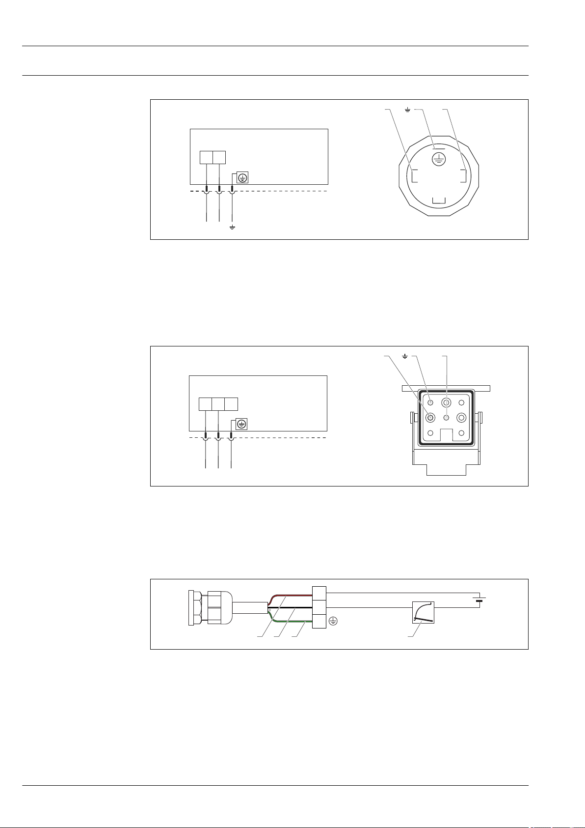
Device plug connectors Devices with valve connector (HART)
+
2 1
–
+
A B
BU BN GNYE
2
1
3
+
–
–
Han7D
–
+
+ –
–
+
1
5
4
6
7
8
2
3
A B
–
+
+
PE
–
1 2 3 4
1 BN = brown, BU = blue, GNYE = green
A Electrical connection for devices with valve connector
B View of the plug connector at the device
Material: PA 6.6
Cerabar M PMC51, PMP51, PMP55
A0023097
Devices with Harting plug Han7D (HART)
A Electrical connection for devices with Harting plug Han7D
B View of the plug-in connector at the device
Material: CuZn, contacts for plug-in jack and connector are gold-plated
Connecting the cable version (all device versions)
A0019990
1 RD = red
2 BK = black
3 GNYE = green
4 4...20 mA
24 Endress+Hauser
A0019991

Cerabar M PMC51, PMP51, PMP55
2
1
3
4
4
2
3
1
Devices with M12 plug(Analog, HART, PROFIBUS PA)
1 Signal +
2 Not assigned
3 Signal –
4 Earth
Endress+Hauser offers the following accessories for devices with an M12 connector:
Plug-in jack M 12x1, straight
• Material: body PA; coupling nut CuZn, nickel-plated
• Degree of protection (fully locked): IP66/67
• Order number: 52006263
Plug-in jack M 12x1, elbowed
• Material: body PBT/PA; coupling nut GD-Zn, nickel-plated
• Degree of protection (fully locked): IP66/67
• Order number: 71114212
Cable 4x0.34 mm2 (20 AWG) with M12 socket, elbowed, screw plug, length 5 m (16 ft)
• Material: body PUR; coupling nut CuSn/Ni; cable PVC
• Degree of protection (fully locked): IP66/67
• Order number: 52010285
A0011175
Devices with 7/8" plug (Analog, HART, FOUNDATION Fieldbus)
1 Signal 2 Signal +
3 Not assigned
4 Shield
External thread: 7/8 - 16 UNC
• Material: 316L (1.4401)
• Protection: IP66/68
Cable specification Analog
• Endress+Hauser recommends using twisted, shielded two-wire cables.
• The cable outer diameter depends on the cable entry used.
HART
• Endress+Hauser recommends using twisted, shielded two-wire cables.
• The cable outer diameter depends on the cable entry used.
A0011176
Endress+Hauser 25

Cerabar M PMC51, PMP51, PMP55
1
2
3
4
+
-
+
-
rt
sw
+
-
A
B
PROFIBUS PA
Use a twisted, shielded two-wire cable, preferably cable type A
For further information on the cable specifications, see Operating Instructions BA00034S
"PROFIBUS DP/PA: Guidelines for planning and commissioning", the PNO Guideline 2.092
PROFIBUS PA User and Installation Guideline" and IEC 61158-2 (MBP).
FOUNDATION Fieldbus
Use a twisted, shielded two-wire cable, preferably cable type A
For further information on the cable specifications, see Operating Instructions BA00013S
"FOUNDATION Fieldbus Overview", FOUNDATION Fieldbus Guideline and IEC 61158-2 (MBP).
Start-up current
Residual ripple
Influence of power supply
Overvoltage protection (optional)
• Analog electronics:: 12 mA
• HART: 12 mA or 22 mA (selectable)
No influence on 4 to 20 mA signal up to ±5 % residual ripple within the permitted voltage range
[according to HART hardware specification HCF_SPEC-54 (DIN IEC 60381-1)].
≤0.001 % of URL/V
The device can be fitted with overvoltage protection. The overvoltage protection is mounted at the
factory on the housing thread (M20x1.5) for the cable gland and is approx. 70 mm (2.76 in) in
length (take additional length into account when installing). The device is connected as illustrated in
the following graphic.
For details refer to TI01013KDE, XA01003KA3 and BA00304KA2.
Ordering information:
Product Configurator, "Mounted accessories" ordering feature, option NA
Wiring
A Without direct shield grounding
B With direct shield grounding
1 Incoming connection cable
2 HAW569-DA2B
3 Unit to be protected
4 Connection cable
26 Endress+Hauser
A0023111

Cerabar M PMC51, PMP51, PMP55
90°
90°
C
A
B
Performance characteristics of the ceramic process isolating diaphragm
Reference operating conditions
Influence of orientation
• As per IEC 60770
• Ambient temperature TA = constant, in the range of +21 to +33 °C (+70 to +91 °F)
•
Humidity j = constant, in the range of: 5 to 80 % RH
• Ambient pressure pU = constant, in the range of:860 to 1 060 mbar (12.47 to 15.37 psi)
• Position of the measuring cell: constant, in the range of: ±1° horizontally
• Input of LOW SENSOR TRIM and HIGH SENSOR TRIM for lower range value and upper range value
• Span based on zero point
• Material of the process isolating diaphragm: Al2O3 (aluminum oxide ceramic Ceraphire®)
• Supply voltage: 24 V DC ±3 V DC
• Load with HART: 250 Ω
A0023697
Measuring error in mbar (psi)
Process isolating diaphragm axis is
horizontal (A)
Calibration position, no measuring error < +0.2 mbar (+0.003 psi) < –0.2 mbar (–0.003 psi)
Position-dependent zero point shift can be corrected at the device → 36
Uncertainty of measurement for small absolute pressure ranges
The smallest expanded uncertainty of measurement that can be returned by our standards is:
• 0.4% of the measured value in the range of 1 to 30 mbar (0.0145 to 0.435 psi)
• 1% of the measured value in the range < 1 mbar (0.0145 psi).
Process isolating diaphragm
pointing upwards (B)
Process isolating diaphragm
pointing downwards (C)
Endress+Hauser 27

Cerabar M PMC51, PMP51, PMP55
Reference accuracy – PMC51
The reference accuracy comprises the non-linearity according to limit point setting, hysteresis and
non-reproducibility as per IEC 60770. The data refer to the calibrated span.
Gauge pressure sensors
Measuring cell Standard reference accuracy Platinum reference accuracy
100 mbar (1.5 psi) • TD 1:1 to ≤ TD 10:1 = ±0.15 %
• TD > 10:1 to TD 20:1 = ±0.2 %
250 mbar (3.75 psi),
400 mbar (6 psi),
1 bar (15 psi),
2 bar (30 psi),
4 bar (60 psi),
10 bar (150 psi)
40 bar (600 psi) • TD 1:1 to ≤ TD 10:1 = ±0.15 %
Absolute pressure sensors
Measuring cell Standard reference accuracy Platinum reference accuracy
100 mbar (1.5 psi) • TD 1:1 to ≤ TD 10:1 = ±0.15 %
250 mbar (3.75 psi) • TD 1:1 to ≤ TD 10:1 = ±0.15 %
400 mbar (6 psi),
1 bar (15 psi),
2 bar (30 psi),
4 bar (60 psi),
10 bar (150 psi)
40 bar (600 psi) • TD 1:1 to ≤ TD 10:1 = ±0.15 %
• TD 1:1 to ≤ TD 10:1 = ±0.15 %
• TD > 10:1 to TD 20:1 = ±0.2 %
• TD > 10:1 to TD 20:1 = ±0.2 %
• TD > 10:1 to TD 20:1 = ±0.015 x TD
• TD > 10:1 to TD 20:1 = ±0.2 %
• TD 1:1 to ≤ TD 10:1 = ±0.15 %
• TD > 10:1 to TD 20:1 = ±0.2 %
• TD > 10:1 to TD 20:1 = ±0.2 %
• TD 1:1 to ≤ TD 10:1 = ±0.075 %
• TD > 10:1 to TD 20:1 = ±0.0075 % x TD
• TD 1:1 to ≤ TD 10:1 = ±0.075 %
• TD > 10:1 to TD 20:1 = ±0.1 %
• TD 1:1 to ≤ TD 10:1 = ±0.075 %
• TD > 10:1 to TD 20:1 = ±0.0075 % x TD
• TD 1:1 to ≤ TD 10:1 = ±0.075 %
• TD > 10:1 to TD 20:1 = ±0.015 % x TD
• TD 1:1 to ≤ TD 10:1 = ±0.075 %
• TD > 10:1 to TD 20:1 = ±0.1 %
• TD 1:1 to ≤ TD 10:1 = ±0.075 %
• TD > 10:1 to TD 20:1 = ±0.1 %
• TD 1:1 to ≤ TD 10:1 = ±0.075 %
• TD > 10:1 to TD 20:1 = ±0.0075 % x TD
Thermal change in the zero output and the output span – PMC51
Signal output Measuring cell % of the calibrated measuring span
HART,
PROFIBUS PA,
FOUNDATION Fieldbus
Analog
(4 to 20 mA)
100 mbar (1.5 psi),
250 mbar (3.75 psi),
400 mbar (6 psi)
1 bar (15 psi), 2 bar (30 psi),
4 bar (60 psi), 10 bar (150 psi),
40 bar (600 psi)
100 mbar (1.5 psi),
250 mbar (3.75 psi),
400 mbar (6 psi)
1 bar (15 psi), 2 bar (30 psi),
4 bar (60 psi), 10 bar (150 psi),
40 bar (600 psi)
PMC51 with thread or flange
–40 to –20 °C
(–40 to –4 °F)
±(0.6 + 0.45 x TD) ±0.2 + 0.275 x TD ±(0.4 + 0.425 x TD)
±0.5 + 0.35 x TD ±0.1 + 0.15 x TD ±(0.225 + 0.525 x TD)
±(0.6 + 0.45 x TD) ±0.4 + 0.275 x TD ±0.7 + 0.425 x TD
±0.5 + 0.35 x TD ±0.3 + 0.15 x TD ±0.525 + 0.525 x TD
–10 to +60 °C
(+14 to +140 °F)
–20 to +100 °C
(–4 to +212 °F)
28 Endress+Hauser

Cerabar M PMC51, PMP51, PMP55
PMC51 with hygienic process connection
Signal output Measuring cell % of the calibrated measuring span
HART,
PROFIBUS PA,
FOUNDATION Fieldbus
Analog
(4 to 20 mA)
100 mbar (1.5 psi),
250 mbar (3.75 psi),
400 mbar (6 psi)
1 bar (15 psi), 2 bar (30 psi),
4 bar (60 psi),
10 bar (150 psi),
40 bar (600 psi)
100 mbar (1.5 psi),
250 mbar (3.75 psi),
400 mbar (6 psi)
1 bar (15 psi), 2 bar (30 psi),
4 bar (60 psi),
10 bar (150 psi),
40 bar (600 psi)
–10 to +60 °C
(+14 to +140 °F)
±(0.4 + 0.275 x TD) ±(0.7 + 0.425 x TD)
±(0.3 + 0.15 x TD) ±(0.525 + 0.525 x TD)
±(0.4 + 0.275 x TD) ±(0.7 + 0.425 x TD)
±(0.3 + 0.15 x TD) ±(0.525 + 0.525 x TD)
–20 to +130 °C
(–4 to +266 °F)
Total performance – PMC51
The "Total performance" specification comprises the non-linearity including hysteresis, nonreproducibility as well as the thermal change in the zero point. All specifications apply to the
temperature range –10 to +60 °C (+14 to +140 °F) and Turndown 1:1.
Signal output Measuring cell % URL
HART,
PROFIBUS PA,
FOUNDATION Fieldbus
Analog
(4 to 20 mA)
100 mbar (1.5 psi), 250 mbar (3.75 psi),
400 mbar (6 psi)
1 bar (15 psi), 2 bar (30 psi), 4 bar (60 psi), 10 bar (150 psi),
40 bar (600 psi)
100 mbar (1.5 psi), 250 mbar (3.75 psi),
400 mbar (6 psi)
1 bar (15 psi), 2 bar (30 psi), 4 bar (60 psi), 10 bar (150 psi),
40 bar (600 psi)
Long-term stability For devices with thread or flange:
Measuring range Long-term stability of
URL / 1 year
PMC51 ≤ 1 bar (15 psi) ±0.2 % ±0.4 % ±0.5 %
> 1 bar (15 psi) ±0.1 % ±0.25 % ±0.4 %
For devices with hygienic process connections:
Long-term stability of
URL / 5 years
±0.575
±0.5
±0.775
±0.7
Long-term stability of
URL / 10 years
Measuring range Long-term stability of URL / 1 year
PMC51 ≤ 1 bar (15 psi) ±0.35 %
> 1 bar (15 psi) ±0.2 %
Endress+Hauser 29

Cerabar M PMC51, PMP51, PMP55
Total Error - PMC51
The total error comprises the long-term stability and the total performance. All specifications apply
to the temperature range –10...+60 °C (+14...+140 °F) and Turndown 1:1.
Signal output Measuring cell % URL / 1
PMC51 with thread or flange HART, PROFIBUS PA, FOUNDATION
Fieldbus
Analog (4 to 20 mA) 100 mbar (1.5 psi), 250 mbar (3.75 psi),
PMC51 with hygienic process
connection
Warm-up period
HART, PROFIBUS PA, FOUNDATION
Fieldbus
Analog (4 to 20 mA) 100 mbar (1.5 psi), 250 mbar (3.75 psi),
• 4 to 20 mA analog: ≤1,5 s
• 4 to 20 mA HART: ≤5 s
• PROFIBUS PA: ≤8 s
• FOUNDATION Fieldbus: ≤20 s (after a TOTAL-reset ≤45 s)
100 mbar (1.5 psi), 250 mbar (3.75 psi),
400 mbar (6 psi)
1 bar (15 psi), 2 bar (30 psi), 4 bar (60 psi),
10 bar (150 psi), 40 bar (600 psi)
400 mbar (6 psi)
1 bar (15 psi), 2 bar (30 psi), 4 bar (60 psi),
10 bar (150 psi), 40 bar (600 psi)
100 mbar (1.5 psi), 250 mbar (3.75 psi),
400 mbar (6 psi)
1 bar (15 psi), 2 bar (30 psi), 4 bar (60 psi),
10 bar (150 psi), 40 bar (600 psi)
400 mbar (6 psi)
1 bar (15 psi), 2 bar (30 psi), 4 bar (60 psi),
10 bar (150 psi), 40 bar (600 psi)
Jahr
±0.55
±0.47
±0.75
±0.67
±0.925
±0.7
±1.125
±0.9
30 Endress+Hauser
 Loading...