

Page 1
KA01024P/00/EN/18.16
71336239
Products Solutions Services
Brief Operating Instructions
Deltabar S
PMD75, FMD77, FMD78
Differential pressure measurement
These Instructions are Brief Operating Instructions; they are not
a substitute for the Operating Instructions pertaining to the
device.
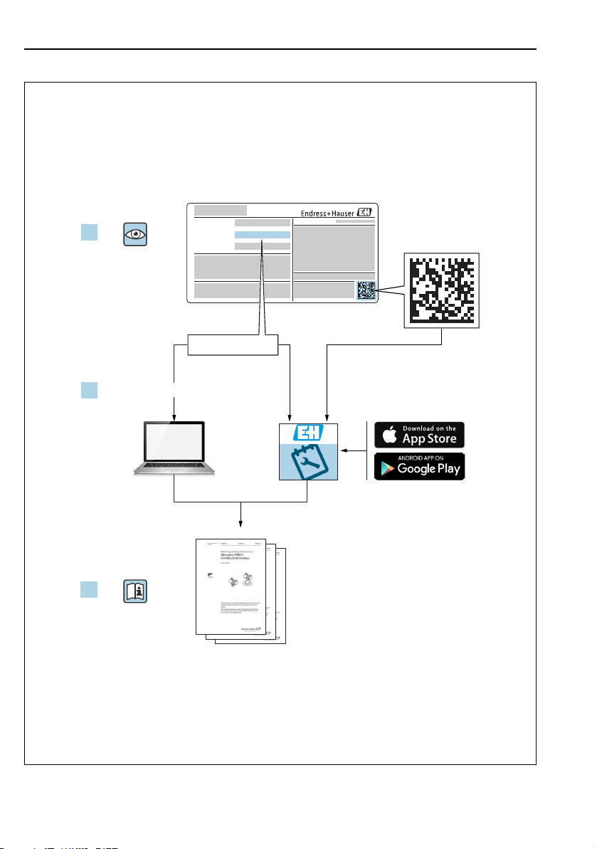
Detailed information about the device can be found in the
Operating Instructions and the other documentation:
Available for all device versions via:
– Internet: www.endress.com/deviceviewer
– Smart phone/tablet: Endress+Hauser Operations App
Page 2
Deltabar S FOUNDATION Fieldbus
Order code:
Ext. ord. cd.:
Ser. no.:
www.endress.com/deviceviewer
Endress+Hauser
Operations App
XXXXXXXXXXXX
XXXXX-XXXXXX
XXX.XXXX.XX
Serial number
1.
3.
2.
2 Endress+Hauser
A0023555
Page 3

Deltabar S FOUNDATION Fieldbus Table of contents
Table of contents
1 Document information . . . . . . . . . . . . . . . . . . . . . . . . . . . . . . . . . . . . . . . . . . . . . . . . . . . . . . . . . 4
1.1 Document function . . . . . . . . . . . . . . . . . . . . . . . . . . . . . . . . . . . . . . . . . . . . . . . . . . . . . . . . . . . . . . . . . . . . . . . . . . . . . . . . . . 4
1.2 Symbols used . . . . . . . . . . . . . . . . . . . . . . . . . . . . . . . . . . . . . . . . . . . . . . . . . . . . . . . . . . . . . . . . . . . . . . . . . . . . . . . . . . . . . . . 4
1.3 Registered trademarks . . . . . . . . . . . . . . . . . . . . . . . . . . . . . . . . . . . . . . . . . . . . . . . . . . . . . . . . . . . . . . . . . . . . . . . . . . . . . . . 6
1.4 Terms and abbreviations . . . . . . . . . . . . . . . . . . . . . . . . . . . . . . . . . . . . . . . . . . . . . . . . . . . . . . . . . . . . . . . . . . . . . . . . . . . . . . 7
1.5 Turn down calculation . . . . . . . . . . . . . . . . . . . . . . . . . . . . . . . . . . . . . . . . . . . . . . . . . . . . . . . . . . . . . . . . . . . . . . . . . . . . . . . . 8
2 Basic safety instructions . . . . . . . . . . . . . . . . . . . . . . . . . . . . . . . . . . . . . . . . . . . . . . . . . . . . . . . . 9
2.1 Requirements concerning the staff . . . . . . . . . . . . . . . . . . . . . . . . . . . . . . . . . . . . . . . . . . . . . . . . . . . . . . . . . . . . . . . . . . . . . 9
2.2 Designated use . . . . . . . . . . . . . . . . . . . . . . . . . . . . . . . . . . . . . . . . . . . . . . . . . . . . . . . . . . . . . . . . . . . . . . . . . . . . . . . . . . . . . . 9
2.3 Workplace safety . . . . . . . . . . . . . . . . . . . . . . . . . . . . . . . . . . . . . . . . . . . . . . . . . . . . . . . . . . . . . . . . . . . . . . . . . . . . . . . . . . . . 9
2.4 Operational safety . . . . . . . . . . . . . . . . . . . . . . . . . . . . . . . . . . . . . . . . . . . . . . . . . . . . . . . . . . . . . . . . . . . . . . . . . . . . . . . . . . . 9
2.5 Hazardous area . . . . . . . . . . . . . . . . . . . . . . . . . . . . . . . . . . . . . . . . . . . . . . . . . . . . . . . . . . . . . . . . . . . . . . . . . . . . . . . . . . . . 10
2.6 Product safety . . . . . . . . . . . . . . . . . . . . . . . . . . . . . . . . . . . . . . . . . . . . . . . . . . . . . . . . . . . . . . . . . . . . . . . . . . . . . . . . . . . . . . 10
3 Identification. . . . . . . . . . . . . . . . . . . . . . . . . . . . . . . . . . . . . . . . . . . . . . . . . . . . . . . . . . . . . . . . .10
3.1 Product identification . . . . . . . . . . . . . . . . . . . . . . . . . . . . . . . . . . . . . . . . . . . . . . . . . . . . . . . . . . . . . . . . . . . . . . . . . . . . . . . 10
3.2 Device designation . . . . . . . . . . . . . . . . . . . . . . . . . . . . . . . . . . . . . . . . . . . . . . . . . . . . . . . . . . . . . . . . . . . . . . . . . . . . . . . . . . 11
3.3 Scope of delivery . . . . . . . . . . . . . . . . . . . . . . . . . . . . . . . . . . . . . . . . . . . . . . . . . . . . . . . . . . . . . . . . . . . . . . . . . . . . . . . . . . . 11
3.4 CE mark, Declaration of Conformity . . . . . . . . . . . . . . . . . . . . . . . . . . . . . . . . . . . . . . . . . . . . . . . . . . . . . . . . . . . . . . . . . . . 12
3.5 Registered trademarks . . . . . . . . . . . . . . . . . . . . . . . . . . . . . . . . . . . . . . . . . . . . . . . . . . . . . . . . . . . . . . . . . . . . . . . . . . . . . . 12
4 Installation . . . . . . . . . . . . . . . . . . . . . . . . . . . . . . . . . . . . . . . . . . . . . . . . . . . . . . . . . . . . . . . . . .13
4.1 Incoming acceptance and storage . . . . . . . . . . . . . . . . . . . . . . . . . . . . . . . . . . . . . . . . . . . . . . . . . . . . . . . . . . . . . . . . . . . . . 13
4.2 Installation conditions . . . . . . . . . . . . . . . . . . . . . . . . . . . . . . . . . . . . . . . . . . . . . . . . . . . . . . . . . . . . . . . . . . . . . . . . . . . . . . . 14
4.3 Installation instructions . . . . . . . . . . . . . . . . . . . . . . . . . . . . . . . . . . . . . . . . . . . . . . . . . . . . . . . . . . . . . . . . . . . . . . . . . . . . . 14
4.4 Post-installation check . . . . . . . . . . . . . . . . . . . . . . . . . . . . . . . . . . . . . . . . . . . . . . . . . . . . . . . . . . . . . . . . . . . . . . . . . . . . . . 21
5 Wiring . . . . . . . . . . . . . . . . . . . . . . . . . . . . . . . . . . . . . . . . . . . . . . . . . . . . . . . . . . . . . . . . . . . . . .22
5.1 Connecting the device . . . . . . . . . . . . . . . . . . . . . . . . . . . . . . . . . . . . . . . . . . . . . . . . . . . . . . . . . . . . . . . . . . . . . . . . . . . . . . . 22
5.2 Connecting the measuring unit . . . . . . . . . . . . . . . . . . . . . . . . . . . . . . . . . . . . . . . . . . . . . . . . . . . . . . . . . . . . . . . . . . . . . . . 23
5.3 Overvoltage protection (optional) . . . . . . . . . . . . . . . . . . . . . . . . . . . . . . . . . . . . . . . . . . . . . . . . . . . . . . . . . . . . . . . . . . . . . 24
5.4 Post-connection check . . . . . . . . . . . . . . . . . . . . . . . . . . . . . . . . . . . . . . . . . . . . . . . . . . . . . . . . . . . . . . . . . . . . . . . . . . . . . . 24
6 Operation. . . . . . . . . . . . . . . . . . . . . . . . . . . . . . . . . . . . . . . . . . . . . . . . . . . . . . . . . . . . . . . . . . . . 25
6.1 Onsite display (optional) . . . . . . . . . . . . . . . . . . . . . . . . . . . . . . . . . . . . . . . . . . . . . . . . . . . . . . . . . . . . . . . . . . . . . . . . . . . . . 25
6.2 Operating elements . . . . . . . . . . . . . . . . . . . . . . . . . . . . . . . . . . . . . . . . . . . . . . . . . . . . . . . . . . . . . . . . . . . . . . . . . . . . . . . . . 27
6.3 FOUNDATION Fieldbus interface . . . . . . . . . . . . . . . . . . . . . . . . . . . . . . . . . . . . . . . . . . . . . . . . . . . . . . . . . . . . . . . . . . . . . 30
6.4 Local operation – onsite display connected . . . . . . . . . . . . . . . . . . . . . . . . . . . . . . . . . . . . . . . . . . . . . . . . . . . . . . . . . . . . . 31
6.5 HistoROM®/M-DAT (optional) . . . . . . . . . . . . . . . . . . . . . . . . . . . . . . . . . . . . . . . . . . . . . . . . . . . . . . . . . . . . . . . . . . . . . . . 35
6.6 FieldCare . . . . . . . . . . . . . . . . . . . . . . . . . . . . . . . . . . . . . . . . . . . . . . . . . . . . . . . . . . . . . . . . . . . . . . . . . . . . . . . . . . . . . . . . . . 35
6.7 Locking/unlocking operation . . . . . . . . . . . . . . . . . . . . . . . . . . . . . . . . . . . . . . . . . . . . . . . . . . . . . . . . . . . . . . . . . . . . . . . . . 35
6.8 Simulation . . . . . . . . . . . . . . . . . . . . . . . . . . . . . . . . . . . . . . . . . . . . . . . . . . . . . . . . . . . . . . . . . . . . . . . . . . . . . . . . . . . . . . . . . 36
6.9 Factory setting (reset) . . . . . . . . . . . . . . . . . . . . . . . . . . . . . . . . . . . . . . . . . . . . . . . . . . . . . . . . . . . . . . . . . . . . . . . . . . . . . . . 36
7 Commissioning . . . . . . . . . . . . . . . . . . . . . . . . . . . . . . . . . . . . . . . . . . . . . . . . . . . . . . . . . . . . . . .36
7.1 Configuring messages . . . . . . . . . . . . . . . . . . . . . . . . . . . . . . . . . . . . . . . . . . . . . . . . . . . . . . . . . . . . . . . . . . . . . . . . . . . . . . . 36
7.2 Function check . . . . . . . . . . . . . . . . . . . . . . . . . . . . . . . . . . . . . . . . . . . . . . . . . . . . . . . . . . . . . . . . . . . . . . . . . . . . . . . . . . . . . 36
7.3 Commissioning via an FF configuration program . . . . . . . . . . . . . . . . . . . . . . . . . . . . . . . . . . . . . . . . . . . . . . . . . . . . . . . . 37
7.4 Selecting the language and measuring mode . . . . . . . . . . . . . . . . . . . . . . . . . . . . . . . . . . . . . . . . . . . . . . . . . . . . . . . . . . . 37
7.5 Position adjustment . . . . . . . . . . . . . . . . . . . . . . . . . . . . . . . . . . . . . . . . . . . . . . . . . . . . . . . . . . . . . . . . . . . . . . . . . . . . . . . . . 37
7.6 Flow measurement . . . . . . . . . . . . . . . . . . . . . . . . . . . . . . . . . . . . . . . . . . . . . . . . . . . . . . . . . . . . . . . . . . . . . . . . . . . . . . . . . 38
7.7 Level measurement . . . . . . . . . . . . . . . . . . . . . . . . . . . . . . . . . . . . . . . . . . . . . . . . . . . . . . . . . . . . . . . . . . . . . . . . . . . . . . . . . 42
7.8 Differential pressure measurement . . . . . . . . . . . . . . . . . . . . . . . . . . . . . . . . . . . . . . . . . . . . . . . . . . . . . . . . . . . . . . . . . . . . 48
7.9 Scaling the OUT parameter . . . . . . . . . . . . . . . . . . . . . . . . . . . . . . . . . . . . . . . . . . . . . . . . . . . . . . . . . . . . . . . . . . . . . . . . . . 51
Endress+Hauser 3
Page 4
Document information Deltabar S FOUNDATION Fieldbus
DANGER
WARNING
CAUTION
NOTICE
)
1 Document information
1.1 Document function
These Operating Instructions contain all the information that is required in various phases of
the life cycle of the device: from product identification, incoming acceptance and storage, to
mounting, connection, operation and commissioning through to troubleshooting, maintenance
and disposal.
1.2 Symbols used
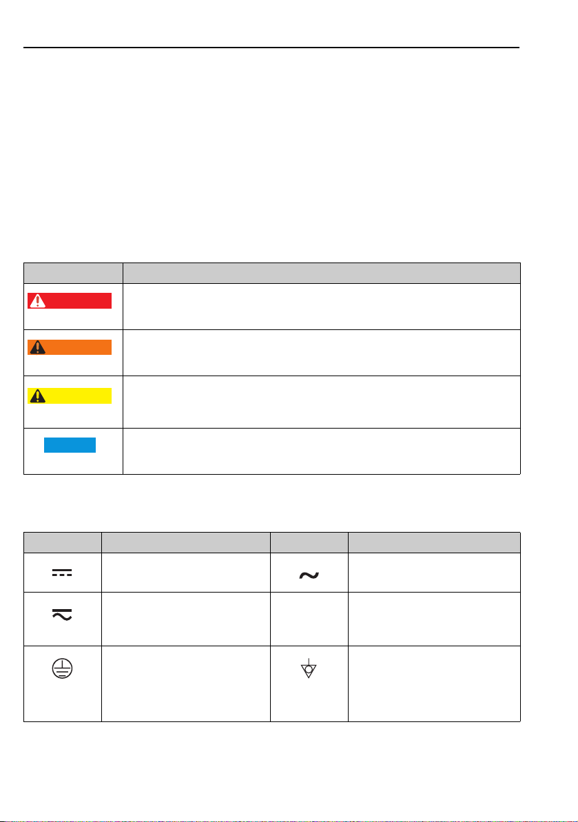
1.2.1 Safety symbols
Symbol Meaning
DANGER!
This symbol alerts you to a dangerous situation. Failure to avoid this situation will result in
A0011189-DE
A0011190-DE
A0011191-DE
A0011192-DE
seriousor fatal injury.
WARNING!
This symbol alerts you to a dangerous situation. Failure to avoid this situation can result in
seriousor fatal injury.
CAUTION!
This symbol alerts you to a dangerous situation. Failure to avoid this situation can result in
minoror medium injury.
NOTICE!
This symbol contains information on procedures and other facts which do not result in
personalinjury.
1.2.2 Electrical symbols
Symbol Meaning Symbol Meaning
Direct current Alternating current
Direct current and alternating current Ground connection
Protective ground connection
A terminal which must be connected to
ground prior to establishing any other
connections.
4 Endress+Hauser
A grounded terminal which, as far as
the operator is concerned, is grounded
via a grounding system.
Equipotential connection
A connection that has to be connected
to the plant grounding system: This may
be a potential equalization line or a star
grounding system depending on
national or company codes of practice.
Page 5
Deltabar S FOUNDATION Fieldbus Document information
,…,
1.
2.
3.
1.2.3 Tool symbols
Symbol Meaning
Allen key
A0011221
Hexagon wrench
A0011222
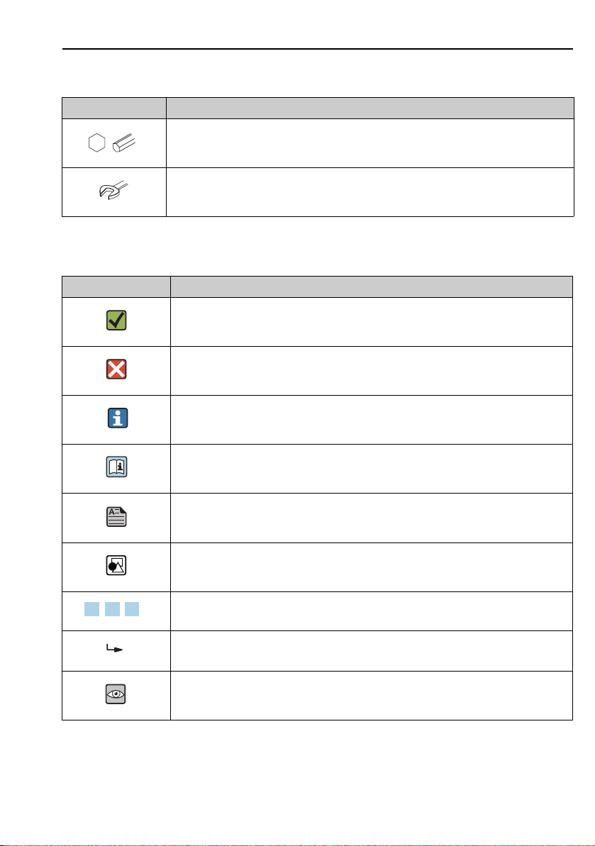
1.2.4 Symbols for certain types of information
Symbol Meaning
Permitted
Indicates procedures, processes or actions that are permitted.
A0011182
Forbidden
Indicates procedures, processes or actions that are forbidden.
A0011184
Tip
Indicates additional information.
A0011193
Reference to documentation
A0015482
Reference to page
A0015484
Reference to graphic
A0015487
Series of steps
A0031595
Result of a sequence of actions
A0018343
Visual inspection
A0015502
Endress+Hauser 5
Page 6
Document information Deltabar S FOUNDATION Fieldbus
,…,
1.
2.
3.
1.2.5 Symbols in graphics
Symbol Meaning
1, 2, 3, 4, ... Item numbers
Series of steps
A0031595
A, B, C, D, ... Views
1.2.6 Symbols at the device
Symbol Meaning
Safety instructions
Observe the safety instructions contained in the associated Operating Instructions.
A0019159
1.3 Registered trademarks
KALREZ, VITON, TEFLON
Registered trademarks of E.I. Du Pont de Nemours & Co., Wilmington, USA
TRI-CLAMP
Registered trademark of Ladish & Co., Inc., Kenosha, USA
FOUNDATIONTM Fieldbus
Registered trademark of the FieldComm Group, Austin, USA
GORE-TEX
Registered trademarks of W.L. Gore & Associates, Inc., USA
®
6 Endress+Hauser
Page 7
Deltabar S FOUNDATION Fieldbus Document information
URL OPLMWP
LRL
0
p
LRV
URV
1
2
3
4
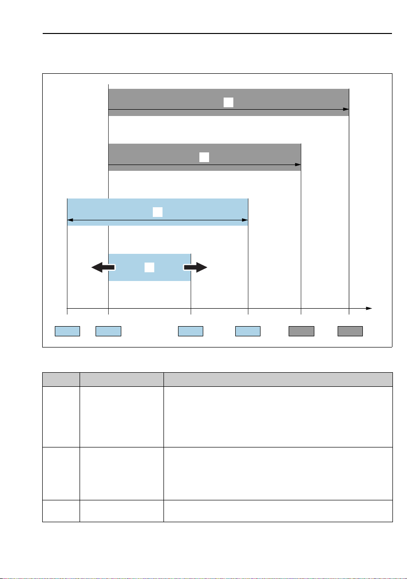
1.4 Terms and abbreviations
Position Term/Abbreviation Explanation
1 OPL The OPL (over pressure limit = sensor overload limit) for the sensors depends
2 MWP The MWP (maximum working pressure) for the sensors depends on the
3 Maximum sensor
measuring range
Endress+Hauser 7
on the lowest-rated element, with regard to pressure, of the selected
components, i.e. the process connection must be taken into consideration in
addition to the measuring cell. Also observe pressure-temperature
dependency. For the relevant standards and additional notes, see technical
information.
The OPL may be applied for a limited time period.
lowest-rated element, with regard to pressure, of the selected components,
i.e. the process connection has to be taken into consideration in addition to
the measuring cell. Also observe pressure-temperature dependency. For the
relevant standards and additional notes, see technical information.
The MWP may be applied for an unlimited time.
Range between LRL and URL
This span is the maximum calibratable/adjustable measuring span.
A0029505
Page 8
Document information Deltabar S FOUNDATION Fieldbus
LRV
URLURV
LRL
1 = 2
3
Position Term/Abbreviation Explanation
4 Calibrated/Adjusted
measuring span
p - Pressure
- LRL Lower range limit
- URL Upper range limit
- LRV Lower range value
- URV Upper range value
-TD Turn down
Range between LRV and URV
Factory setting: 0...URL
Other calibrated spans can be ordered with customised settings.
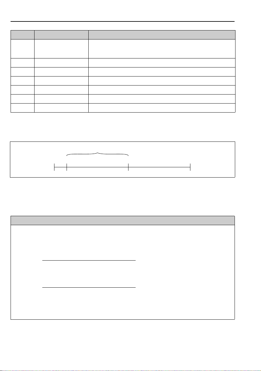
1.5 Turn down calculation
Fig. 1:
1 Calibrated/Adjusted measuring span
2Zero-based span
3 Upper range limit
Example
• Sensor: 10 bar (150 psi)
• Upper range limit (URL) = 10 bar (150 psi)
Turn down (TD):
TD =
TD =
In this example, the TD is thus 2:1.
This span is based on the zero point.
8 Endress+Hauser
|URV - LRV|
|5 bar (75 psi) - 0 bar (0 psi)|
URL
10 bar (150 psi)
• Calibrated/Adjusted measuring span: 0...5 bar
(0...75 psi)
• Lower range value (LRV) = 0 bar
• Upper range value (URV) = 5 bar (75 psi)
=2
A0029545
Page 9

Deltabar S FOUNDATION Fieldbus Basic safety instructions
2 Basic safety instructions
2.1 Requirements concerning the staff
The personnel for installation, commissioning, diagnostics and maintenance must fulfill the
following requirements:
• Trained, qualified specialists: must have a relevant qualification for this specific function and
task
• Are authorized by the plant owner/operator
• Are familiar with federal/national regulations
• Before beginning work, the specialist staff must have read and understood the instructions in
the Operating Instructions and supplementary documentation as well as in the certificates
(depending on the application)
• Following instructions and basic conditions
The operating personnel must fulfill the following requirements:
• Being instructed and authorized according to the requirements of the task by the facility's
owner-operator
• Following the instructions in these Operating Instructions
2.2 Designated use
The Deltabar S is a differential pressure transmitter for measuring differential pressure, flow
and level.
2.2.1 Incorrect use
The manufacturer is not liable for damage caused by improper or non-designated use.
Verification for borderline cases:
For special fluids and fluids for cleaning, Endress+Hauser is glad to provide assistance in
verifying the corrosion resistance of fluid-wetted materials, but does not accept any warranty or
liability.
2.3 Workplace safety
For work on and with the device:
• Wear the required personal protective equipment according to federal/national regulations.
• Switch off the supply voltage before connecting the device.
2.4 Operational safety
Risk of injury!
‣ Operate the device in proper technical condition and fail-safe condition only.
‣ The operator is responsible for interference-free operation of the device.
Endress+Hauser 9
Page 10

Identification Deltabar S FOUNDATION Fieldbus
Conversions to the device
Unauthorized modifications to the device are not permitted and can lead to unforeseeable
dangers:
‣ If, despite this, modifications are required, consult with Endress+Hauser.
Repair
To ensure continued operational safety and reliability,
‣ Carry out repairs on the device only if they are expressly permitted.
‣ Observe federal/national regulations pertaining to repair of an electrical device.
‣ Use original spare parts and accessories from Endress+Hauser only.
2.5 Hazardous area
To eliminate a danger for persons or for the facility when the device is used in the hazardous
area (e.g. explosion protection, pressure vessel safety):
• Based on the nameplate, check whether the ordered device is permitted for the intended use
in the hazardous area.
• Observe the specifications in the separate supplementary documentation that is an integral
part of these Instructions.
2.6 Product safety
This measuring device is designed in accordance with good engineering practice to meet
state-of-the- art safety requirements, has been tested, and left the factory in a condition in
which they are safe to operate. It fulfills general safety requirements and legal requirements. It
also conforms to the EC directives listed in the device-specific EC declaration of conformity.
Endress+Hauser confirms this fact by applying the CE mark.
3 Identification
3.1 Product identification
The following options are available for identification of the measuring device:
• Nameplate specifications
• Order code with breakdown of the device features on the delivery note
• Enter serial numbers from nameplates in W@M Device Viewer
(www.endress.com/deviceviewer): All information about the measuring device is displayed.
For an overview of the technical documentation provided, enter the serial number from the
nameplates in the W@M Device Viewer (www.endress.com/deviceviewer).
10 Endress+Hauser
Page 11

Deltabar S FOUNDATION Fieldbus Identification
3.2 Device designation
3.2.1 Nameplates
• The MWP (maximum working pressure) is specified on the nameplate. This value refers to a
reference temperature of +20 °C (68°F) and may be applied to the device for an unlimited
time. Observe temperature dependency of the MWP. The pressure values permitted at higher
temperatures can be found in the standards EN 1092-1: 2001 Tab. 18 (With regard to their
stability-temperature property, the materials 1.4435 and 1.4404 are grouped together under
13EO in EN 1092-1 Tab. 18. The chemical composition of the two materials can be identical.),
ASME B 16.5a – 1998 Tab. 2-2.2 F316, ASME B 16.5a – 1998 Tab. 2.3.8 N10276, JIS B
2220.
• For PMD75, the MWP applies for the temperature ranges specified in the Technical
Information TI00382P in the "Ambient temperature range" and "Process temperature limits"
sections.
• The test pressure corresponds to the over pressure limit (OPL) of the device = MWP x 1.5.
• The Pressure Equipment Directive (2014/68/EU) uses the abbreviation "PS".
The abbreviation "PS" corresponds to the MWP (maximum working pressure) of the
measuring device.
3.2.2 Identifying the sensor type
See parameter "Sensor Meas.Type" in Operating Instruction BA00303P.
3.3 Scope of delivery
The scope of delivery comprises:
• Deltabar S differential pressure transmitter
• For PMD75 with side flanges made of AISI 316L or C22.8: additionally 2 vent valves, AISI
316L
• PMD75 with side flanges made of AISI 316L or C22.8 and side vent: additionally 4 locking
screws, AISI 316L
• For devices with the "HistoROM/M-DAT" option: CD-ROM with Endress+Hauser operating
program
• Optional accessories
Documentation supplied:
• Operating Instructions BA00301P and BA00303P are available via the Internet.
See: www.endress.com Download.
• Brief Operating Instructions KA01024P
• Fold-out brochure KA00252P
• Final inspection report
• Additional Safety Instructions with ATEX, IECEx and NEPSI devices
• Optional: factory calibration form, test certificates
Endress+Hauser 11
Page 12

Identification Deltabar S FOUNDATION Fieldbus
3.4 CE mark, Declaration of Conformity
The devices are designed to meet state-of-the-art safety requirements, have been tested and left
the factory in a condition in which they are safe to operate. The devices comply with the
applicable standards and regulations as listed in the EC Declaration of Conformity and thus
comply with the statutory requirements of the EC Directives. Endress+Hauser confirms the
conformity of the device by affixing to it the CE mark.
3.5 Registered trademarks
KALREZ, VITON, TEFLON
Registered trademarks of E.I. Du Pont de Nemours & Co., Wilmington, USA
TRI-CLAMP
Registered trademark of Ladish & Co., Inc., Kenosha, USA
FOUNDATIONTM Fieldbus
Registered trademark of the Fieldbus Foundation Austin, Texas, USA
12 Endress+Hauser
Page 13
Deltabar S FOUNDATION Fieldbus Installation
NOTICE
WARNING
!
1
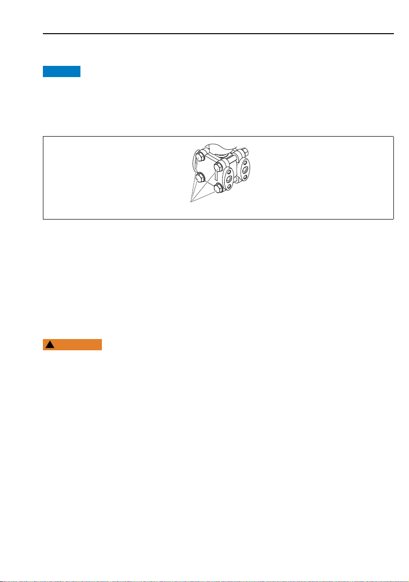
4 Installation
Incorrect handling!
Damage of the device!
‣ Disassembly of the screws with item number (1) is not permissible under any circumstances
and will result in loss of warranty.
A0025336
4.1 Incoming acceptance and storage
4.1.1 Incoming acceptance
• Check the packaging and the contents for damage.
• Check the shipment, make sure nothing is missing and that the scope of supply matches your
order.
4.1.2 Transport
Incorrect transport
Housing and diaphragm may be damaged and and there is a risk of injury!
‣ Transport the measuring device to the measuring point in its original packaging or by the
process connection (with secure transport protection for the diaphragm).
‣ Follow the safety instructions and transport conditions for devices of more than 18 kg
(39.69 lbs).
‣ Do not use capillaries as a carrying aid for the diaphragm seals.
4.1.3 Storage
The device must be stored in a dry, clean area and protected against impact (EN 837-2).
Storage temperature range:
• –40 to +90°C (–40 to +194 °F)
• Onsite display: –40 to +85°C (–40 to +185°F)
• Separate housing: –40 to +60°C (–40 to +140°F)
Endress+Hauser 13
Page 14

Installation Deltabar S FOUNDATION Fieldbus
4.2 Installation conditions
4.2.1 Dimensions
For dimensions, please refer to the Technical Information for Deltabar S TI00382P,
"Mechanical construction" section.
4.3 Installation instructions
• Due to the orientation of the Deltabar S, there may be a shift in the measured value, i.e. when
the container is empty or partially full, the measured value does not display zero. You can
correct this zero point shift using the "Zero" key on the electronic insert or externally on the
device or via the onsite display. ä 27, Section 6.2.1 "Position of the operating elements",
ä 29, Section 6.2.3 "Function of the operating elements – onsite display connected" and
ä 37, Section 7.5 "Position adjustment"..
• For FMD77 and FMD78, please refer to Section 4.3.4 "Installation instructions for devices
with diaphragm seals (FMD78)", ä 16.
• General recommendations for routing the pressure piping can be found in DIN 19210
"Methods for measurement of fluid flow; differential piping for flow measurement devices" or
the corresponding national or international standards.
• Using a three-way or five-way valve manifold allows for easy commissioning, installation and
maintenance without interrupting the process.
• When routing the pressure piping outdoors, ensure that sufficient antifreeze protection is
used, e.g. by using pipe heat tracing.
• Install the pressure piping with a monotonic gradient of at least 10%.
• To ensure optimal readability of the onsite display, it is possible to rotate the housing up to
380°. ä 20, Section 4.3.9 "Rotating the housing".
• Endress+Hauser offers a mounting bracket for installing on pipes or walls.
ä 18, Section 4.3.7 "Wall and pipe-mounting (optional)".
4.3.1 Installation for flow measurement
Flow measurement in gases with PMD75
• Mount the Deltabar S above the measuring point so that the condensate can run off into the
process piping.
Flow measurement in steam with PMD75
• Mount the Deltabar S below the measuring point.
• Mount the condensate traps at the same level as the tapping points and at the same distance
to the Deltabar S.
• Prior to commissioning, fill the pressure piping to the level of the condensate traps.
Flow measurement in liquids with PMD75
• Mount the Deltabar S below the measuring point so that the pressure piping is always filled
with liquid and gas bubbles can run back into the process piping.
14 Endress+Hauser
Page 15

Deltabar S FOUNDATION Fieldbus Installation
• When measuring in media with solid parts, such as dirty liquids, installing separators and
drain valves is useful for capturing and removing sediment.
4.3.2 Installation for level measurement
Level measurement in an open container with PMD75
• Mount the Deltabar S below the lower measuring connection so that the pressure piping is
always filled with liquid.
• The negative side is open to atmospheric pressure.
• When measuring in media with solid parts, such as dirty liquids, installing separators and
drain valves is useful for capturing and removing sediment.
Level measurement in an open container with FMD77
• Mount the Deltabar S directly on the container. ä 18, Section 4.3.5 "Seal for flange
mounting".
• The negative side is open to atmospheric pressure.
Level measurement in a closed container with PMD75
• Mount the Deltabar S below the lower measuring connection so that the pressure piping is
always filled with liquid.
• Always connect the impulse piping of negative side above the maximum level.
• When measuring in media with solid parts, such as dirty liquids, installing separators and
drain valves is useful for capturing and removing sediment.
Level measurement in a closed container with FMD77
• Mount the Deltabar S directly on the container. ä 18, Section 4.3.5 "Seal for flange
mounting".
• Always connect the impulse piping of negative side above the maximum level.
• When measuring in media with solid parts, such as dirty liquids, installing separators and
drain valves is useful for capturing and removing sediment.
Level measurement in a closed container with FMD78
• Mount the Deltabar S below the lower diaphragm seal. ä 16, Section 4.3.4 "Installation
instructions for devices with diaphragm seals (FMD78)".
• The ambient temperature should be the same for both capillaries.
Level measurement is only ensured between the upper edge of the lower diaphragm seal and
the lower edge of the upper diaphragm seal.
Level measurement in a closed container with superimposed steam with PMD75
• Mount the Deltabar S below the lower measuring connection so that the pressure piping is
always filled with liquid.
• Always connect the impulse piping of negative side above the maximum level.
Endress+Hauser 15
Page 16

Installation Deltabar S FOUNDATION Fieldbus
NOTICE
• A condensate trap ensures constant pressure on the negative side.
• When measuring in media with solid parts, such as dirty liquids, installing separators and
drain valves is useful for capturing and removing sediment.
Level measurement in a closed container with superimposed steam with FMD77
• Mount the Deltabar S directly on the container. ä 18, Section 4.3.5 "Seal for flange
mounting".
• Always connect the impulse piping of negative side above the maximum level.
• A condensate trap ensures constant pressure on the negative side.
• When measuring in media with solid parts, such as dirty liquids, installing separators and
drain valves is useful for capturing and removing sediment.
4.3.3 Installation for differential pressure measurement
Differential pressure measurement in gases and steam with PMD75
• Mount the Deltabar S above the measuring point so that the condensate can run off into the
process piping.
Differential pressure measurement in liquids with PMD75
• Mount the Deltabar S below the measuring point so that the pressure piping is always filled
with liquid and gas bubbles can run back into the process piping.
• When measuring in media with solid parts, such as dirty liquids, installing separators and
drain valves is useful for capturing and removing sediment.
Differential pressure measurement in gases, steam and liquids with FMD78
• Mount the diaphragm seal with capillaries at the top or on the side on the piping.
• For vacuum applications: mount the Deltabar S below the measuring point. ä 17,
Section 4.3.4, "Vacuum application (FMD78)".
• The ambient temperature should be the same for both capillaries.
4.3.4 Installation instructions for devices with diaphragm seals (FMD78)
• Please note that the hydrostatic pressure of the liquid columns in the capillaries can cause
zero point shift. The zero point shift can be corrected.
• Do not clean or touch the process isolating diaphragm of the diaphragm seal with hard or
pointed objects.
• Do not remove process isolating diaphragm protection until shortly before installation.
Improper handling!
Damage to the device!
‣ A diaphragm seal and the pressure transmitter together form a closed, oil-filled calibrated
system. The fill fluid hole is sealed and may not be opened.
16 Endress+Hauser
Page 17

Deltabar S FOUNDATION Fieldbus Installation
NOTICE
+ –
+
–
≥ 100 mm
‣ When using a mounting bracket, sufficient strain relief must be ensured for the capillaries
in order to prevent the capillary bending down (bending radius 100 (3.94 in)).
‣ Please observe the application limits of the diaphragm seal filling oil as detailed in the
Technical Information for Deltabar S TI00382P, "Planning instructions for diaphragm seal
systems" section.
In order to obtain more precise measurement results and to avoid a defect in the device,
mount the capillaries as follows:
‣ Vibration-free (in order to avoid additional pressure fluctuations)
‣ Not in the vicinity of heating or cooling lines
‣ Insulate if the ambient temperature is below or above the reference temperature
‣ With a bending radius of 100 mm (3.94 in).
‣ Do not use the capillaries as a carrying aid for the diaphragm seals!
‣ The ambient temperature and length of both capillaries should be the same when using
two-sided diaphragm seal systems.
‣ Two diaphragm seals which are the same (e.g. with regard to diameter, material, etc.)
should always be used for the negative and positive side (standard delivery).
Fig. 2: Mounting Deltabar S, FMD78 with diaphragm seals and capillaries, recommended mounting for vacuum
applications: mount pressure transmitter below the lowest diaphragm seal!
P01-FMD78xxx-11-xx-xx-xx-005
Vacuum application (FMD78)
See operrating instructions.
Endress+Hauser 17
Page 18

Installation Deltabar S FOUNDATION Fieldbus
NOTICE
12
4.3.5 Seal for flange mounting
Distorted measurement results.
The seal is not allowed to press on the process isolating diaphragm as this could affect the
measurement result.
‣ Ensure that the seal is not touching the process isolating diaphragm.
Fig. 3:
1 Process isolating diaphragm
2Seal
A0017743
4.3.6 Heat insulation – FMD77
See operrating instructions.
4.3.7 Wall and pipe-mounting (optional)
Endress+Hauser offers the following mounting brackets for installing the device on pipes or
walls:
18 Endress+Hauser
Page 19

Deltabar S FOUNDATION Fieldbus Installation
NOTICE
Standard design Heavy duty design
A0031326 A0031327
The standard mounting bracket version is not suitable for use in an application subject to
vibrations.
The vibration resistance of the reinforced version of the mounting bracket has been tested
according to IEC 61298-3, see the "Vibration resistance" section in the technical documentation
TI00382P.
When using a valve block, the block's dimensions must be taken into account.
Bracket for wall and pipe mounting including retaining bracket for pipe mounting and two nuts.
material of the screws used to secure the device depend on the order code.
Technical data (e.g. dimensions or order numbers for screws) see accessory document
SD01553P/00/EN.
Incorrect handling!
Damage of the device!
‣ Disassembly of the screws with item number (1) is not permissible under any circumstances
and will result in loss of warranty.
Endress+Hauser 19
Page 20

Installation Deltabar S FOUNDATION Fieldbus
1
2
1
2
T14
T15
T17
2 3
A0025335
4.3.8 Assembling and mounting the "separate housing" version
See operrating instructions.
4.3.9 Rotating the housing
The housing can be rotated up to 380° by loosening the Allen screw.
1. T14 housing: Loosen setscrew with a 2 mm (0.08 in) Allen key.
T15 andT17 housing: Loosen setscrew with a 3 mm (0.12 in) Allen key.
2. Rotate housing (max. up to 380 °).
3. Retighten setscrew with 1 Nm (0,74 lbf ft.
20 Endress+Hauser
A0019996
Page 21

Deltabar S FOUNDATION Fieldbus Installation
NOTICE
NOTICE
+
–
4.3.10 Closing the housing cover
Devices with EPDM cover seal - transmitter leakiness!
Mineral-based, animal-based or vegetable-based lubricants cause the EPDM cover seal to swell
and the transmitter to become leaky.
‣ The thread is coated at the factory and therefore does not require any lubrication.
The housing cover can no longer be closed.
Damaged thread!
‣ When closing the housing cover, please ensure that the thread of the cover and housing are
free from dirt, e.g. sand.If you feel any resistance when closing the cover, check the thread
on both again to ensure that they are free from dirt.
Closing the covers on the hygienic stainless steel housing (T17)
Fig. 4: Closing the covers
P01-PMD75xxx-17-xx-xx-xx-000
The covers for the terminal and electronics compartment are hooked into the housing and
closed with a screw. These sc rews should be tig htened handtight (2 Nm (1.48 lbf ft)) to the stop
to ensure that the covers sit tightly.
4.4 Post-installation check
After installing the device, carry out the following checks:
• Are all screws firmly tightened?
• Are the housing covers screwed down tight?
• Are all locking screws and vent valves firmly tightened?
Endress+Hauser 21
Page 22

Wiring Deltabar S FOUNDATION Fieldbus
WARNING
!
WARNING
!
5 Wiring
5.1 Connecting the device
Risk of electric shock!
If the operating voltage is > 35 VDC: Dangerous contact voltage at terminals.
‣ In a wet environment, do not open the cover if voltage is present.
Limitation of electrical safety due to incorrect connection!
• Risk of electric shock and/or explosion in hazardous areas! In a wet environment, do not open
the cover if voltage is present.
• When using the measuring device in hazardous areas, installation must comply with the
corresponding national standards and regulations and the Safety Instructions or Installation
or Control Drawings.
• Devices with integrated overvoltage protection must be grounded.
• Protective circuits against reverse polarity, HF influences and overvoltage peaks are installed.
• The supply voltage must match the power supply on the nameplate. ( ä 11, Section 3.2.1
"Nameplates".)
• Switch off the supply voltage before connecting the device.
• Remove the housing cover of the terminal compartment.
• Guide the cable through the gland. For cable specifications, ä 24, Section 5.2.4.
• Connect the device in accordance with the following diagram.
• Screw down the housing cover.
• Switch on the supply voltage.
22 Endress+Hauser
Page 23

Deltabar S FOUNDATION Fieldbus Wiring
➀
➁
➂
➃
➄
FF FF
FF FF
4
2
31
Fig. 5: Electrical connection of FOUNDATION Fieldbus
Please refer also to Section 5.2.1 "Supply voltage",
1Housing
2 Internal ground terminal
3 External ground terminal
4 Supply voltage, for version in non-hazardous area = 9 to 32 V DC
5 Devices with integrated overvoltage protection are labeled OVP (overvoltage protection) here.
ä
24.
5.1.1 Connecting devices with 7/8" plug
PIN assignment for 7/8" connector PIN Meaning
PIN Meaning
1 Signal –
2 Signal +
3Shield
4 Not assigned
A0011176
5.2 Connecting the measuring unit
For further information on the network structure and grounding and for further bus system
components such as bus cables, see the relevant documentation, e.g. Operating Instructions
BA00013S "FOUNDATION Fieldbus Overview" and the FOUNDATION Fieldbus Guideline.
P01-xMx7xxxx-04-xx-xx-xx-009
Endress+Hauser 23
Page 24

Wiring Deltabar S FOUNDATION Fieldbus
WARNING
!
5.2.1 Supply voltage
• Version for non-hazardous area: 9 to 32 V DC
Supply voltage might be connected!
Risk of electric shock and/or explosion!
‣ When using the measuring device in hazardous areas, installation must comply with the
corresponding national standards and regulations and the Safety Instructions or Installation
or Control Drawings.
‣ All explosion protection data are given in separate documentation which is available upon
request. The Ex documentation is supplied as standard with all devices approved for use in
explosion hazardous areas.
5.2.2 Current consumption
15.5 mA ±1 mA, switch-on current corresponds to IEC 61158-2, Clause 21.
5.2.3 Terminals
2
• Supply voltage and internal ground terminal: 0.5 to 2.5 mm
• External ground terminal: 0.5 to 4 mm2 (20 to 12 AWG)
5.2.4 Cable specification
• Use a twisted, shielded two-wire cable, preferably cable type A.
• Outer cable diameter: 5 to 9 mm (0.2 to 0.35 in)
For further information on the cable specifications, see Operating Instructions BA00013S
"FOUNDATION Fieldbus Overview", FOUNDATION Fieldbus Guideline and IEC 61158-2 (MBP).
(20 to 14 AWG)
5.2.5 Grounding and shielding
Deltabar S must be grounded, for example by means of the external ground terminal.
Different grounding and shielding installation methods are available for FOUNDATION Fieldbus
networks such as:
• Isolated installation (see also IEC 61158-2)
• Installation with multiple grounding
• Capacitive installation
5.3 Overvoltage protection (optional)
See operrating instructions.
5.4 Post-connection check
Perform the following checks after completing electrical installation of the device:
• Does the supply voltage match the specifications on the nameplate?
• Is the device connected as per Section 5.1?
24 Endress+Hauser
Page 25

Deltabar S FOUNDATION Fieldbus Operation
• Are all screws firmly tightened?
• Are the housing covers screwed down tight?
As soon as voltage is applied to the device, the green LED on the electronic insert lights up for a
few seconds or the connected onsite display lights up.
6Operation
Feature 20 "Output; operation" in the order code provides you with information on the operating
options available to you.
Versions in the order code Operation
P FOUNDATION Fieldbus; external operation, LCD Via onsite display and 1 key on the exterior of the
Q FOUNDATION Fieldbus; internal operation, LCD Via onsite display and 1 key on the inside of the
R FOUNDATION Fieldbus; internal operation Without onsite display, 1 key on the inside of the
6.1 Onsite display (optional)
A 4-line liquid crystal display (LCD) is used for display and operation. The onsite display shows
measured values, fault messages and notice messages. The display of the device can be turned
in 90° steps. Depending on the orientation of the device, this makes it easy to operate the device
and read the measured value.
Functions:
• 8-digit measured value display including sign and decimal point, unit display
• Bar graph as graphic display of the current pressure measured value in relation to the set
pressure range in the Pressure Transducer Block. The pressure range is set by means of the
SCALE_IN parameter.
• Easy and complete menu guidance by dividing the parameters into several levels and groups
•Menu guidance
The onsite display is available in English. Needless to say, the device can also be operated in
6 languages (de, en, fr, es, jp, ch) via the DTM or EDD. The FieldCare program is an E+H DTM
operating tool and can be acquired from endress.com.
• Each parameter has a 3-digit ID to aid navigation
• Option of configuring the display according to individual requirements and preferences, such
as alternating display, contrast setting, display of other measured values such as sensor
temperature
• Comprehensive diagnostic functions (fault and warning message, maximum indicator, etc.)
• Rapid and safe commissioning using Quick Setup menus
device
device
device
Endress+Hauser 25
Page 26

Operation Deltabar S FOUNDATION Fieldbus
E
+
–
Bargraph
Operating keys
Symbol
Bargraph
ValueFunction name
Unit
Header line
Information
line
Main line
Parameter
Identification
number
Editing modes
Selection
options
Value that
can be edited
Current measured
value
Measured value display
P01-xxxxxxxx-07-xx-xx-en-011
26 Endress+Hauser
Page 27

Deltabar S FOUNDATION Fieldbus Operation
The following table illustrates the symbols that can appear on the onsite display. Four symbols
can occur at one time.
Symbol Meaning
Alarm symbol
– Symbol flashing: warning, device continues measuring.
– Symbol permanently lit: error, device does not continue measuring.
Note: The alarm symbol may overlie the tendency symbol.
Lock symbol
The operation of the device is locked. Unlock device, ä 35, Section 6.7
"Locking/unlocking operation".
Communication symbol
Data transfer via communication
Square root symbol
Active measuring mode "Flow measurement"
Simulation symbol
Simulation mode is activated. DIP switch 2 for simulation is set to "On".
See also Section 6.2.1 "Position of the operating elements" and ä 36, Section 6.8
"Simulation".
Tendency symbol (increasing)
The primary value of the Pressure Transducer Block is increasing.
Tendency symbol (decreasing)
The primary value of the Pressure Transducer Block is decreasing.
Tendency symbol (constant)
The primary value of the Pressure Transducer Block has remained constant over the past
few minutes.
6.2 Operating elements
6.2.1 Position of the operating elements
On the aluminum housing (T14/T15), the operating key is located either under the protective
flap on the exterior of the device or inside on the electronic insert. In the case of the hygienic
stainless steel housing (T17), the operating key is always inside on the electronic insert. In
addition, there are three operating keys on the optional onsite display.
Endress+Hauser 27
Page 28

Operation Deltabar S FOUNDATION Fieldbus
➀
0%
Zero
HW
21
PC
1
2
➀➁
➃
on
off
➂
➄
➅
Sim.
Sensor
on
off
Simulation
0%
Zero
Display
Histo
ROM
0%
Zero
1
2
on
off
Sim.
Fig. 6: Operating key external, under the protective flap
1 Operating key for position adjustment (zero point
correction) and total reset
P01-xMD7xxxx-19-xx-xx-xx-074
Fig. 7: Operating keys, internal
1 Green LED to indicate value is accepted
2 Operating key for position adjustment (zero point
correction) and total reset
3 Slot for optional display
4 Slot for optional HistoROM
5 DIP switch for locking/unlocking parameters relevant
to the measured value
®
/M-DAT
6 DIP switch for simulation mode
6.2.2 Function of operating elements
Key(s) Meaning
– Position adjustment (zero point correction): press key for at least 3 seconds. The LED
on the electronic insert lights up briefly if the pressure applied has been accepted for
position adjustment.
See also the following section "Performing position adjustment on site".
– Total reset: press key for at least 12 seconds. The LED on the electronic insert lights
P02-xxxxxxxx-19-xx-xx-xx-107
Performing position adjustment on site
• Operation must be unlocked. ä 35, Section 6.7 "Locking/unlocking operation".
P01-xxxxxxxx-19-xx-xx-xx-134
up briefly if a reset is being carried out.
– DIP switch 1: for locking/unlocking parameters relevant to the measured value.
Factory setting: off (unlocked)
ä 35, Section 6.7 "Locking/unlocking operation".
– DIP switch 2: for simulation mode
Factory setting: off (simulation mode off)
ä 36, Section 6.8 "Simulation"
P01-xxxxxxxx-19-xx-xx-xx-106
28 Endress+Hauser
Page 29

Deltabar S FOUNDATION Fieldbus Operation
• The device is configured for the Pressure measuring mode as standard.
– Operation via FF configuration program: In the Pressure Transducer Block, change the
measuring mode by means of the PRIMARY_VALUE_TYPE and LINEARIZATION
parameters.
– Operation via digital communication: change the measuring mode by means of the
MEASURING MODE parameter.
– You can change the measuring mode by means of the MEASURING MODE parameter.
ä 37, Section 7.4 "Selecting the language and measuring mode".
• The pressure applied must be within the nominal pressure limits of the sensor. See
information on the nameplate.
Perform position adjustment:
1. Pressure is present at device.
2. Press key for at least 3 seconds.
3. If the LED on the electronic insert lights up briefly, the pressure applied has been accepted
for position adjustment.
If the LED does not light up, the pressure applied was not accepted. Observe the input
limits. For error messages see operating instructions..
6.2.3 Function of the operating elements – onsite display connected
Key(s) Meaning
– Navigate upwards in the picklist
– Edit numerical values or characters within a function
– Navigate downwards in the picklist
– Edit numerical values or characters within a function
–Confirm entry
– Go to next item
Contrast setting of onsite display: increase
O
O
S
F
and
F
and
S
F
and
O
Endress+Hauser 29
S
Contrast setting of onsite display: reduce
ESC functions:
– Exit the editing mode without saving the altered value
– You are in the menu within a function group: the first time you press the keys
simultaneously, you go back one parameter in the function group. Every subsequent
time you press the keys simultaneously, you go up one level in the menu.
– You are in the menu on a selection level: every time you press the keys
simultaneously, you go up one level in the menu.
Note: For the terms function group, level, selection level, ä 31, Section 6.4.1
Page 30

Operation Deltabar S FOUNDATION Fieldbus
1
2
on
off
Sim.
Key(s) Meaning
– DIP switch 1: for locking/unlocking parameters relevant to the measured value.
Factory setting: off (unlocked)
– DIP switch 2: for the simulation mode Factory setting: off (simulation mode off)
P01-xxxxxxxx-19-xx-xx-xx-134
6.3 FOUNDATION Fieldbus interface
See operating instructions.
6.3.1 Device identification and addressing
FOUNDATION Fieldbus identifies the device using its ID code and automatically assigns it a
suitable field address. The identity code cannot be changed.
The device appears in the network display once you have started the FF configuration program
and integrated the device into the network. The blocks available are displayed under the device
name.
If the device description has not yet been loaded, the blocks report "Unknown" or "(UNK)".
Deltabar S reports as follows:
30 Endress+Hauser
Page 31

Deltabar S FOUNDATION Fieldbus Operation
–
–
RS_XXXXXXXXXXX (RB2)
EH_DeltabarS-XXXXXXXXXXXXXXXX
➀➁
TRD1_(PCD)XXXXXXXXXXX
SERVICE_(SERVICE)XXXXXXXXXXX
DIAGNOSTIC_(DIAGNOSTIC)XXXXXXXXXXX
DISPLAY_ (DISP)XXXXXXXXXXX
AI1_ (AI)XXXXXXXXXXX
AI2_ (AI)XXXXXXXXXXX
DO_(DO)XXXXXXXXXXX
PID_(PID)XXXXXXXXXXX
ARTH_ (ARB)XXXXXXXXXXX
CHAR_ (SCB)XXXXXXXXXXX
ISEL_ (ISB)XXXXXXXXXXX
INTG_ (ITB)XXXXXXXXXXX
AALM_ (AALB)XXXXXXXXXXX
DI_ (DI)XXXXXXXXXXX
DP_FLOW_(DPFLOW)XXXXXXXXXXX
AI3_ (AI)XXXXXXXXXXX
Fig. 8: Typical Deltabar S display in a configuration program after the connection has been established
1Device name
2 Serial number
P01-xMx7xxxx-05-xx-xx-xx-005
6.4 Local operation – onsite display connected
If the onsite display is connected, the three operating keys are used to navigate through the
operating menu, ä 29, Section 6.2.3 "Function of the operating elements – onsite display
connected".
6.4.1 Menu structure
The menu is split into four levels. The three upper levels are used to navigate while you use the
lowest level to enter numerical values, and select and save options.
The structure of the MEASURING MENU depends on the measuring mode selected, e.g. if
"Pressure" is selected as the measuring mode, only the functions needed for this measuring mode
are displayed.
Endress+Hauser 31
Page 32

Operation Deltabar S FOUNDATION Fieldbus
➀
➂
➁
➃
Measured value
GROUP SELECTION
DISPLAYSETTINGS
EXTENDED SETUP
POS. ZERO ADJUST
POS. INPUT VALUE
CALIB. OFFSET
POSITION ADJUSTMENT BASIC SETUP
OPERATING MENU
QUICK SETUP
MEASURING MODELANGUAGE
Fig. 9: Menu structure
1 1st selection level
2 2nd selection level
3Function groups
4 Parameters
The MEASURING MODE parameter is only displayed via the onsite display on the 1st selection
P01-xxxxxxxx-19-xx-xx-xx-145
level. In FieldCare, the LANGUAGE parameter is displayed in the DISPLAY group and the
parameters for configuring the measuring mode are displayed in the Measuring Mode menu.
32 Endress+Hauser
Page 33

Deltabar S FOUNDATION Fieldbus Operation
6.4.2 Selecting an option
Example: Selecting the "Pressure" measuring mode.
Onsite display Operation
"Flow" has been selected as the measuring mode. The
option currently active is indicated by a 3in front of the
menu text.
MEASURINGMODE_Flow
Use "+" or "–" to select "Pressure" as the operating mode.
MEASURINGMODE_Press
1. Press "E" to confirm your choice. The option
currently active is indicated by a 3 in front of the
menu text. (The "Pressure" measuring mode is
selected.)
2. Go to the next menu item with "E" .
MEASURINGMODE_Press-1
6.4.3 Editing a value
Example: changing the DAMPING VALUE function from 2.0 s to 30.0 s. ä 29, Section 6.2.3
"Function of the operating elements – onsite display connected".
Onsite display Operation
The onsite display indicates the parameter to be
modified. The value highlighted in black can be
modified. The unit "s" is prespecified and cannot be
changed.
P01-xxxxxxxx-19-xx-xx-en-023
Endress+Hauser 33
Page 34

Operation Deltabar S FOUNDATION Fieldbus
Onsite display Operation
1. Press "+" or "–" to enter the editing mode.
2. The first digit is highlighted in black.
P01-xxxxxxxx-19-xx-xx-en-027
1. Use the "+" key to change the digit "2" to "3".
2. Press the "E" key to confirm "3". The cursor goes to
the next position (highlighted in black).
P01-xxxxxxxx-19-xx-xx-en-028
The decimal point is highlighted in black. This means
you can now edit this digit.
P01-xxxxxxxx-19-xx-xx-en-029
1. Press "+" or "–" until "0" is displayed.
2. Press the "E" key to confirm "0".
The cursor goes to the next position. is
displayed and highlighted in black. See next
graphic.
P01-xxxxxxxx-19-xx-xx-en-030
Press "E" to save the new value and exit the editing
mode. See next graphic.
P01-xxxxxxxx-19-xx-xx-en-031
The new value for the damping is 30.0 s.
– Go to the next parameter with "E" .
– Press "+" or "–" to go back to the editing mode.
P01-xxxxxxxx-19-xx-xx-en-032
34 Endress+Hauser
Page 35

Deltabar S FOUNDATION Fieldbus Operation
6.4.4 Accepting pressure present at device as value
Example: performing position adjustment.
Onsite display Operation
The bottom line on the onsite display displays the
pressure present, 3.9 mbar in this example.
P01-xxxxxxxx-19-xx-xx-en-158
Use "+" or "–" to switch to the "Confirm" option. The
active option is highlighted in black.
P01-xxxxxxxx-19-xx-xx-en-159
Using the "E" key, assign the value (3.9 mbar) to the
POS. ZERO ADJUST parameter. The device confirms
the adjustment and goes back to the parameter, here
POS. ZERO ADJUST (see next graphic).
P01-xxxxxxxx-19-xx-xx-en-037
Go to the next parameter with "E" .
P01-xxxxxxxx-19-xx-xx-en-160
6.5 HistoROM®/M-DAT (optional)
See operating instructions.
6.6 FieldCare
See operating instructions.
6.7 Locking/unlocking operation
See operating instructions.
Endress+Hauser 35
Page 36

Commissioning Deltabar S FOUNDATION Fieldbus
WARNING
!
NOTICE
6.8 Simulation
See operating instructions.
6.9 Factory setting (reset)
See operating instructions.
7 Commissioning
The device is configured for the Pressure measuring mode as standard. The measuring range
and the unit in which the measured value is transmitted correspond to the specifications on the
nameplate.
Exceeding the maximum allowable working pressure!
Risk of injury due to bursting of parts! Warning messages are generated if pressure is too high.
‣ If a pressure greater than the maximum permitted pressure is present at the device, the
messages "E115 Sensor overpressure" and "E727 Sensor pressure error - overrange" are
output in succession! Use the device only within the sensor range limits
Shortfall of the allowable working pressure!
Output of messages if pressure is too low.
‣ If a pressure smaller than the minimum permitted pressure is present at the device, the
messages "E120 Sensor low pressure" and "E727 Sensor pressure error - overrange" are
output in succession! Use the device only within the sensor range limits
7.1 Configuring messages
• The messages E727, E115 and E120 are "Error"-type messages and can be configured as a
"Warning" or an "Alarm". The factory setting for these messages is "Warning". This setting
prevents the BAD status from being transmitted in applications (e.g. cascade measurement)
where the user is aware of the risk of the sensor range being overshot.
• We recommend setting messages E727, E115 and E120 to "Alarm" in the following instances:
– It is not necessary to violate the sensor range for the measuring application.
– A position adjustment must be carried out that has to correct a large measured error as a
result of the orientation of the device.
7.2 Function check
Carry out a post-installation and a post-connection check as per the checklist before
commissioning the device.
• "Post-installation check" checklist see Section 4.4
36 Endress+Hauser
Page 37

Deltabar S FOUNDATION Fieldbus Commissioning
• "Post-connection check" checklist see Section 5.4
7.3 Commissioning via an FF configuration program
See operating instructions.
7.4 Selecting the language and measuring mode
7.4.1 Local operation
The MEASURING MODE parameter is on the 1st selection level. ä 31, Section 6.4.1 "Menu
structure".
The following measuring modes are available:
• Pressure
• Level
•Flow
7.4.2 Selecting the language and measuring mode by means of the FieldCare operating program
See operating instructions.
7.5 Position adjustment
Due to the orientation of the device, there may be a shift in the measured value, i.e. when the
container is empty or partly filled, the measured value parameter does not display zero. There
are three options to choose from when performing position adjustment.
• Onsite display menu path: GROUP SELECTION OPERATING MENU SETTINGS
POSITION ADJUSTMENT
• FieldCare menu path: OPERATING MENU SETTINGS POSITION ADJUSTMENT
7.5.1 Performing position adjustment via the onsite display or FieldCare
The parameters listed in the following table can be found in the POSITION ADJUSTMENT group
(menu path: OPERATING MENU SETTINGS POSITION ADJUSTMENT).
Endress+Hauser 37
Page 38

Commissioning Deltabar S FOUNDATION Fieldbus
Parameter name Description
POS. ZERO ADJUST
Entry
POS. INPUT VALUE
Input
CALIB. OFFSET
Entry
Position adjustment – the pressure difference between zero (set point) and the
measured pressure need not be known.
Example:
– MEASURED VALUE = 2.2 mbar (0.032 psi)
– Correct the MEASURED VALUE via the POS. ZERO ADJUST parameter with the
"Confirm" option. This means that you are assigning the value 0.0 to the pressure
present.
– MEASURED VALUE (after pos. zero adjust) = 0.0 mbar
The CALIB. OFFSET parameter displays the resulting pressure difference (offset) by
which the MEASURED VALUE was corrected.
Factory setting:
0.0
Position adjustment – the pressure difference between zero (set point) and the
measured pressure need not be known. To correct the pressure difference, you need a
reference measurement value (e. g. from a reference device).
Example:
– MEASURED VALUE = 0.5 mbar (0.0073 psi)
– For the POS. INPUT VALUE parameter, specify the desired set point for the
MEASURED VALUE, e.g. 2.0 mbar (0.029 psi).
(The following applies: MEASURED VALUE
– MEASURED VALUE (after entry for POS. INPUT VALUE) = 2.0 mbar (0.029 psi)
– The CALIB. OFFSET parameter displays the resulting pressure difference (offset) by
which the MEASURED VALUE was corrected.
The following applies: CALIB. OFFSET = MEASURED VALUE
VALUE,
here: CALIB. OFFSET= 0.5 mbar (0.0073 psi) – 2.0 mbar (0.029 psi) = – 1.5 mbar
(0.022 psi)
Factory setting:
0.0
Position adjustment – the pressure difference between zero (set point) and the
measured pressure is known. (A reference pressure is not present at the device.)
Example:
– MEASURED VALUE = 2.2 mbar (0.032 psi)
– Via the CALIB. OFFSET parameter, enter the value by which the MEASURED
VALUE should be corrected. To correct the MEASURED VALUE to 0.0 mbar, you
must enter the value 2.2 here.
(The following applies: MEASURED VALUE
OFFSET)
– MEASURED VALUE (after entry for calib. offset) = 0.0 mbar
Factory setting:
0.0
= POS. INPUT VALUE)
new
= MEASURED VALUE
new
– POS. INPUT
old
old
– CALIB.
7.6 Flow measurement
7.6.1 Preparatory steps
• The Deltabar S PMD75 is usually used for flow measurement.
• Before calibrating the Deltabar S, the pressure piping must be cleaned and the device filled
with fluid. See the following table.
38 Endress+Hauser
Page 39

Deltabar S FOUNDATION Fieldbus Commissioning
I
II
+–
–+
6
6
7
7
–+
3
2 4
A B
A
B
+
1
5
2 4
3
II
I
IIIIII
Valves Meaning Preferred installation
1 Close 3.
2 Fill measuring system with fluid.
Open A, B, 2, 4. Fluid flows in.
1)
3 Clean pressure piping if necessary
– by blowing out with compressed air in the case of
gases
– by rinsing out in the case of liquids.
Close 2 and 4. Block off device.
Open 1 and 5.
Close 1 and 5.
4Vent device.
Open 2 and 4. Introduce fluid.
Close 4. Close negative side.
Open 3. Balance positive and
Open 6 and 7 briefly, then
close them again.
5 Carry out pos. zero adjustment if the following
conditions are met. If the conditions are not met, then
do not carry out the pos. zero adjustment until after step
6. ä 41, Section 7.6.3 and ä 37, Section 7.5.
Conditions:
– The process cannot be blocked off.
– T he tap ping point s (A a nd B) a re at the sa me ge odeti c
height.
6 Set measuring point to operation.
Close 3. Shut off positive side from
Open 4. Connect negative side.
Now
–1
– 2 and 4 are open.
– A and B are open (if present).
7 Carry out pos. zero adjustment if the flow can be blocked
off. In this case, step 5 is not applicable. ä 41,
Section 7.6.3 and ä 37, Section 7.5.
8 Carry out calibration. ä 40, Section 7.6.2
1) For arrangement with 5 valves
, 3, 5, 6 and 7 are closed.
:
Blow out/rinse out
pressure piping.
Close valves after cleaning.
negative side.
Fill device completely with
fluid and remove air.
negative side.
Fig. 10: Above: preferred installation for gases
Below: preferred installation for liquids
I Deltabar S PMD75
II Three-way valve manifold
III Separator
1, 5 Drain valves
2, 4 Inlet valves
3 Equalizing valve
6, 7 Vent valves on Deltabar S
A, B Shutoff valves
P01-xMD7xxxx-11-xx-xx-xx-002
Endress+Hauser 39
Page 40

Commissioning Deltabar S FOUNDATION Fieldbus
WARNING
!
7.6.2 Information on flow measurement
In the "Flow" measuring mode, the device determines a volume or mass flow value from the
differential pressure measured. The differential pressure is generated by means of primary
devices such as Pitot tubes or orifice plates and depends on the volume flow or mass flow. Four
flow measuring modes are available: volume flow, norm volume flow (European norm
conditions), standard volume flow (American standard conditions) and mass flow.
In addition, the Deltabar S software is equipped with two totalizers as standard. The totalizers
add up the volume or the mass flow. The counting function and the unit can be set separately
for both totalizers. The first totalizer (totalizer 1) can be reset to zero at any time while the
second (totalizer 2) totalizes the flow from commissioning onwards and cannot be reset.
• By means of the FieldCare operating program, a Quick Setup menu is available for each of the
measuring modes pressure, level and flow which guides you through the most important basic
functions. With the setting in the MEASURING MODE parameter, you specify which Quick
Setup menu should be displayed. ä 37, Section 7.4 "Selecting the language and measuring
mode". No Quick Setup menus are available for the FF configuration programs.
• For a detailed description of the parameters, see Operating Instructions BA00303P "Cerabar
S/Deltabar S/Deltapilot S, Description of Device Functions"
– FF, Pressure Transducer Block Table
– FF, DP Flow Block Table
– FieldCare, POSITION ADJUSTMENT Table
– FieldCare, BASIC SETUP Table
– FieldCare, EXTENDED SETUP Table
– FieldCare, TOTALIZER SETUP Table
Changing the measuring mode affects the span (URV)!
This situation can result in product overflow.
‣If the measuring mode is changed, the span setting (URV) must be verified in the
"Calibration" "Basic Setup" operating menu and, if necessary, reconfigured!
40 Endress+Hauser
Page 41

Deltabar S FOUNDATION Fieldbus Commissioning
1) 1) 2) 2)
1)
1) On-site display only
2) FieldCare only
PROFILE VIEW
MAX FLOW
MAX. PRESS. FLOW
POS. ZERO ADJUST
DAMPING VALUE
MEASURED VALUE
QUICK SETUP
GROUP SELECTION
MEASURING MODE MEASURING MODELANGUAGE
FlowPressure Level
QUICK SETUP OPERATING MENU
7.6.3 Quick Setup menu for the Flow measuring mode (FieldCare)
Fig. 11: Quick Setup menu for the "Flow" measuring mode
Local operation FieldCare
Measured value display
Onsite display: Switch from the measured value display
to GROUP SELECTION with F .
GROUP SELECTION
Select MEASURING MODE.
MEASURING MODE
Select "Flow" option.
GROUP SELECTION
Select QUICK SETUP menu.
POS. ZERO ADJUST
Due to orientation of the device, there may be a shift in
the measured value. You correct the MEASURED VALUE
via the POS. ZERO ADJUST parameter with the "Confirm"
option, i.e. you assign the value 0.0 to the pressure
present.
MAX. FLOW
Enter maximum flow of primary device.
( See also layout sheet of primary device).
Endress+Hauser 41
Measured value display
Select QUICK SETUP menu.
Measuring Mode
Select the Primary Value Type parameter.
Primary Value Type
Select "Flow" option.
POS. ZERO ADJUST
Due to orientation of the device, there may be a shift in
the measured value. You correct the MEASURED VALUE
via the POS. ZERO ADJUST parameter with the "Confirm"
option, i.e. you assign the value 0.0 to the pressure
present.
MAX. FLOW
Enter maximum flow of primary device.
(See also layout sheet of primary device).
P01-xxxxxxxx-19-xx-xx-en-166
Page 42

Commissioning Deltabar S FOUNDATION Fieldbus
Local operation FieldCare
MAX. PRESS. FLOW
Enter maximum pressure of primary device.
(See also layout sheet of primary device).
DAMPING VALUE
Enter damping time (time constant ). The damping
affects the speed at which all subsequent elements, such
as the onsite display, measured value and the OUT Value
of the Analog Input Block react to a change in the
pressure.
For onsite operation, see also ä 29, Section 6.2.3 "Function of the operating elements –
onsite display connected" and ä 31, Section 6.4 "Local operation – onsite display connected".
7.7 Level measurement
7.7.1 Preparatory steps
Open container
• The Deltabar S PMD75, and FMD77 are usually suitable for level measurement in an open
container.
• FMD77: the device is ready for calibration immediately after opening a shutoff valve (may or
may not be present).
• PMD75: before calibrating the device, the pressure piping must be cleaned and filled with
fluid. See the following table.
42 Endress+Hauser
Page 43

Deltabar S FOUNDATION Fieldbus Commissioning
+
A
B
6
II
I
+
–
p
atm
Valves Meaning Installation
1 Fill container to a level above the lower tap.
2 Fill measuring system with fluid.
Open A. Open shutoff valve.
3Vent device.
Open 6 briefly, then close
it again.
4 Set measuring point to operation.
Now
– B and 6 are closed.
–Axis open.
5 Carry out calibration.
ä 46, Section 7.7.2.
Fill device completely with
fluid and remove air.
Fig. 12: Open container
I Deltabar S PMD75
II Separator
6 Vent valves on Deltabar S
A Shutoff valve
B Drain valve
P01-xMD7xxxx-11-xx-xx-xx-003
Endress+Hauser 43
Page 44

Commissioning Deltabar S FOUNDATION Fieldbus
+
A
B
6
7
3
2
4
1
5
+
–
II
I
IIIIII
Closed container
• All Deltabar S versions are suitable for level measurement in closed containers.
• FMD77: the device is ready for calibration immediately after opening the shutoff valves (may
or may not be present).
• FMD78: the device is ready for calibration immediately.
• PMD75: before calibrating the device, the pressure piping must be cleaned and filled with
fluid. See the following table.
Valves Meaning Installation
1 Fill container to a level above the lower tap.
2 Fill measuring system with fluid.
Close 3. Shut off positive side from
Open A and B. Open shutoff valves.
3 Vent positive side (empty negative side if necessary).
Open 2 and 4. Introduce fluid on positive
Open 6 and 7 briefly, then
close them again.
4 Set measuring point to operation.
Now
– 3, 6 and 7 are closed.
–2, 4, A and B are open.
5 Carry out calibration.
ä 46, Section 7.7.2.
negative side.
side.
Fill positive side
completely with fluid and
remove air.
Fig. 13: Closed container
I Deltabar S PMD75
II Three-way valve manifold
III Separator
1, 2 Drain valves
2, 4 Inlet valves
3 Equalizing valve
6, 7 Vent valve on Deltabar S
A, B Shutoff valve
P01-xMD7xxxx-11-xx-xx-xx-004
44 Endress+Hauser
Page 45

Deltabar S FOUNDATION Fieldbus Commissioning
6
7
+
–
+
A
B
3
2
4
1
5
II
I
IIIIII
Closed container with superimposed steam
• All Deltabar S versions are suitable for level measurement in containers with superimposed
steam.
• FMD77: the device is ready for calibration immediately after opening the shutoff valves (may
or may not be present).
• FMD78: the device is ready for calibration immediately.
• PMD75: before calibrating the device, the pressure piping must be cleaned and filled with
fluid. See the following table.
Valves Meaning Installation
1 Fill container to a level above the lower tap.
2 Fill measuring system with fluid.
Open A and B. Open shutoff valves.
Fill the negative pressure piping to the level of the
condensate trap.
3Vent device.
Open 2 and 4. Introduce fluid.
Close 4. Close negative side.
Open 3. Balance positive and
Open 6 and 7 briefly, then
close them again.
4 Set measuring point to operation.
Close 3. Shut off positive side from
Open 4. Connect negative side.
Now
– 3, 6 and 7 are closed.
–2, 4, A and B are open.
5 Carry out calibration.
ä 46, Section 7.7.2.
negative side.
Fill device completely with
fluid and remove air.
negative side.
Fig. 14: Closed container with superimposed steam
I Deltabar S PMD75
II Three-way valve manifold
III Separator
1, 5 Drain valves
2, 4 Inlet valves
3 Equalizing valve
6, 7 Vent valves on Deltabar S
A, B Shutoff valves
P01-xMD7xxxx-11-xx-xx-xx-005
Endress+Hauser 45
Page 46

Commissioning Deltabar S FOUNDATION Fieldbus
WARNING
!
7.7.2 Information on level measurement
• A Quick Setup menu is available for each of the measuring modes Pressure and Level which
guides you through the most important basic functions. For the "Level" Quick Setup menu,
ä 47.
• Furthermore, three level modes are available for the level measurement, namely "Level easy
pressure", "Level easy height" and "Level standard". For the "Level standard" level mode, you can
choose between the "Linear", "Pressure linearized" and "Height linearized" level types. The table
in the "Overview of level measurement" section that follows provides you with an overview of
the various measuring tasks.
– With regard to the "Level easy pressure" and "Level easy height" level modes, the values
entered are not tested as extensively as in the "Level standard" level mode. In the "Level easy
pressure" and "Level easy height" level modes, the values entered for EMPTY
CALIBRATION/FULL CALIBRATION, EMPTY PRESSURE/FULL PRESSURE and EMPTY
HEIGHT/FULL HEIGHT have to be at least 1% apart. The value will be rejected with a
warning message if the values are too close together . Further limit values are not checked;
i.e. the values entered must be appropriate for the sensor and the measuring task so that
the measuring device can measure correctly.
– The "Level easy pressure" and "Level easy height" level modes comprise fewer parameters
than the "Level standard" mode and are not used to quickly and easily configure a level
application.
– Customer-specific units of level, volume and mass, or a linearization table, can only be
entered in the "Level standard" level mode.
• For a detailed description of the parameters and configuration examples, see Operating
Instructions BA00303P "Cerabar S/Deltabar S/ Deltapilot S, Description of Device Functions".
Changing the measuring mode affects the span (URV)!
This situation can result in product overflow.
‣ If the measuring mode is changed, the span setting (URV) must be verified in the
"Calibration" "Basic Setup" operating menu and, if necessary, reconfigured!
7.7.3 Overview of level measurement
See operating instructions.
46 Endress+Hauser
Page 47

Deltabar S FOUNDATION Fieldbus Commissioning
1) 2)1)
1)
2)
1)
3)
3)
EMPTY CALIB.
FULL CALIB.
LEVEL SELECTION
1) On-site display only
2) FieldCare only
3) – LEVEL SELECTION "Level Easy Pressure"
and CALIBRATION MODE "Wet"
– LEVEL SELECTION = "Level Standard",
LEVEL MODE = "Linear" and
CALIBRATI
ON MODE = "Wet"
PROFILE VIEW
POS. ZERO ADJUST
DAMPING VALUE
MEASURED VALUE
QUICK SETUP
GROUP SELECTION
MEASURING MODEMEASURING MODELANGUAGE
FlowPressure Level
OPERATING MENU
7.7.4 Quick Setup menu for Level measuring mode
• Some parameters are only displayed if other parameters are appropriately configured. For
example, the EMPTY CALIB. parameter is only displayed in the following cases:
– LEVEL SELECTION "Level Easy Pressure" and CALIBRATION MODE "Wet"
– LEVEL SELECTION "Level Standard", LEVEL MODE "Linear" and CALIBRATION MODE "Wet"
You can find the LEVEL MODE and the CALIBRATION MODE parameter in the BASIC
SETTINGS function group.
• The following parameters are set to the following values in the factory:
– LEVEL SELECTION: Level Easy Pressure
– CALIBRATION MODE: Wet
– OUTPUT UNIT or LIN. MEASURAND: %
– EMPTY CALIB: 0.0
– FULL CALIB: 100.0
• The quick setup is suitable for simple and quick commissioning. If you wish to make more
complex settings, e.g. change the unit form "%" to "m", you will have to calibrate using the
BASIC SETTINGS group. See Operating Instructions BA00303P.
Fig. 15: Quick Setup menu for "Level" measuring mode
Endress+Hauser 47
P01-xMD7xxxx-19-xx-xx-en-079
Page 48

Commissioning Deltabar S FOUNDATION Fieldbus
Local operation FieldCare
Measured value display
Onsite display: Switch from the measured value display
to GROUP SELECTION with F .
GROUP SELECTION
Select MEASURING MODE.
MEASURING MODE
Select "Level" option.
LEVEL SELECTION
Select level mode. For an overview see ä 46.
GROUP SELECTION
Select QUICK SETUP menu.
POS. ZERO ADJUST
Due to orientation of the device, there may be a shift in
the measured value. You correct the MEASURED VALUE
via the POS. ZERO ADJUST parameter with the "Confirm"
option, i.e. you assign the value 0.0 to the pressure
present.
EMPTY CALIB.
Enter level for the lower calibration point.
For this parameter, enter a level value which is assigned
to the pressure present at the device.
FULL CALIB.
Enter level for the upper calibration point.
For this parameter, enter a level value which is assigned
to the pressure present at the device.
DAMPING VALUE
Enter damping time (time constant ). The damping
affects the speed at which all subsequent elements, such
as the onsite display, measured value and the OUT Value
of the Analog Input Block react to a change in the
pressure.
1)
1
Measured value display
Select QUICK SETUP menu.
Measuring Mode
Select the Primary Value Type parameter.
Primary Value Type
Select "Level" option.
Level Selection
Select level mode. For an overview see ä 46.
POS. ZERO ADJUST
Due to orientation of the device, there may be a shift in
the measured value. You correct the MEASURED
VALUE via the POS. ZERO ADJUST parameter with the
"Confirm" option, i.e. you assign the value 0.0 to the
pressure present.
EMPTY CALIB.
Enter level for the lower calibration point.
For this parameter, enter a level value which is
assigned to the pressure present at the device.
FULL CALIB.
Enter level for the upper calibration point.
For this parameter, enter a level value which is
assigned to the pressure present at the device.
DAMPING VALUE
Enter damping time (time constant ). The damping
affects the speed at which all subsequent elements,
such as the onsite display, measured value and the OUT
Value of the Analog Input Block react to a change in the
pressure.
1
1
1) – LEVEL SELECTION "Level Easy Pressure" and CALIBRATION MODE "Wet"
– LEVEL SELECTION "Level Standard", LEVEL MODE "Linear" and CALIBRATION MODE "Wet"
For onsite operation, see also ä 29, Section 6.2.3 "Function of the operating elements –
onsite display connected" and ä 31, Section 6.4 "Local operation – onsite display connected".
7.8 Differential pressure measurement
7.8.1 Preparatory steps
• The Deltabar S PMD75 and FMD78 are usually used for differential pressure measurement.
• FMD78: the device is ready for calibration immediately.
48 Endress+Hauser
Page 49

Deltabar S FOUNDATION Fieldbus Commissioning
I
II
+–
–+
6
6
7
7
–+
3
2 4
A B
A
B
+
1
5
2 4
3
II
I
IIIIII
• PMD75: before calibrating the device, the pressure piping must be cleaned and filled with
fluid. See the following table.
Valves Meaning Preferred installation
1 Close 3.
2 Fill measuring system with fluid.
Open A, B, 2, 4. Fluid flows in.
3 Clean pressure piping if necessary:
– by blowing out with compressed air in the case of
gases
– by rinsing out in the case of liquids.
Close 2 and 4. Block off device.
Open 1 and 5.
Close 1 and 5.
4Vent device.
Open 2 and 4. Introduce fluid.
Close 4. Close negative side.
Open 3. Balance positive and
Open 6 and 7 briefly, then
close them again.
5 Set measuring point to operation.
Close 3. Shut off positive side from
Open 4. Connect negative side.
Now
, 3, 5, 6 and 7 are closed.
–1
– 2 and 4 are open.
– A and B are open (if present).
6 Carry out calibration if necessary. ä 50,
Section 7.8.2.
1) For arrangement with 5 valves
1)
Blow out/rinse out
pressure piping.
Close valves after cleaning.
negative side.
Fill device completely with
fluid and remove air.
negative side.
Fig. 16: Above: preferred installation for gases
Below: preferred installation for liquids
I Deltabar S PMD75
II Three-way valve manifold
III Separator
1, 5 Drain valves
2, 4 Inlet valves
3 Equalizing valve
6, 7 Vent valves on Deltabar S
A, B Shutoff valve
P01-xMD7xxxx-11-xx-xx-xx-002
Endress+Hauser 49
Page 50

Commissioning Deltabar S FOUNDATION Fieldbus
WARNING
!
1) 2)1) 2)
1)
1) On-site display only
2) FieldCare only
PROFILE VIEW
POS. ZERO ADJUST
DAMPING VALUE
MEASURED VALUE
QUICK SETUP
GROUP SELECTION
MEASURING MODEMEASURING MODELANGUAGE
FlowPressure Level
OPERATING MENU
7.8.2 Information on differential pressure measurement
• By means of the FieldCare operating program, a Quick Setup menu is available for each of the
measuring modes pressure, level and flow which guides you through the most important basic
functions. With the setting in the MEASURING MODE parameter, you specify which Quick
Setup menu should be displayed. ä 37, Section 7.4 "Selecting the language and measuring
mode". No Quick Setup menus are available for the FF configuration programs.
• For a detailed description of the parameters, see Operating Instructions BA00303P "Cerabar
S/Deltabar S/Deltapilot S, Description of Device Functions"
– FF, Table, Pressure Transducer Block
– FieldCare, Table, POSITION ADJUSTMENT
– FieldCare, Table, BASIC SETUP
– FieldCare, Table, EXTENDED SETUP
Changing the measuring mode affects the span (URV)!
This situation can result in product overflow.
‣ If the measuring mode is changed, the span setting (URV) must be verified in the
"Calibration" "Basic Setup" operating menu and, if necessary, reconfigured!
7.8.3 Quick Setup menu for Pressure measuring mode
Fig. 17: Quick Setup menu for "Pressure" measuring mode
Local operation FieldCare
Measured value display
Onsite display: Switch from the measured value display
to GROUP SELECTION with F .
50 Endress+Hauser
Measured value display
Select QUICK SETUP menu.
P01-xMD7xxxx-19-xx-xx-en-080
Page 51

Deltabar S FOUNDATION Fieldbus Commissioning
Local operation FieldCare
GROUP SELECTION
Select MEASURING MODE.
MEASURING MODE
Select "Pressure" option.
GROUP SELECTION
Select QUICK SETUP menu.
POS. ZERO ADJUST
Due to orientation of the device, there may be a shift in
the measured value. You correct the MEASURED VALUE
via the POS. ZERO ADJUST parameter with the "Confirm"
option, i.e. you assign the value 0.0 to the pressure
present.
DAMPING VALUE
Enter damping time (time constant ). The damping
affects the speed at which all subsequent elements, such
as the onsite display, measured value and the OUT
Value of the Analog Input Block react to a change in the
pressure.
Measuring Mode
Select the Primary Value Type parameter.
Primary Value Type
Select "Pressure" option.
POS. ZERO ADJUST
Due to orientation of the device, there may be a shift in
the measured value. You correct the MEASURED VALUE
via the POS. ZERO ADJUST parameter with the "Confirm"
option, i.e. you assign the value 0.0 to the pressure
present.
DAMPING VALUE
Enter damping time (time constant ). The damping
affects the speed at which all subsequent elements, such
as the onsite display, measured value and the OUT
Value of the Analog Input Block react to a change in the
pressure.
For onsite operation, see also ä 29, Section 6.2.3 "Function of the operating elements –
onsite display connected" and ä 31, Section 6.4 "Local operation – onsite display connected".
7.9 Scaling the OUT parameter
See operating instructions.
Endress+Hauser 51
Page 52

www.addresses.endress.com
71336239
 Loading...