

Page 1
TI00382P/00/EN/28.17
71374973
Products
Solutions Services
Technical Information
Deltabar S
PMD75, FMD77, FMD78
Differential pressure measurement and pressure
measurement
Differential pressure transmitter with metal
sensors
Applications
The device is used for the following measuring tasks:
• Flow measurement (volume flow or mass flow) in conjunction with differential
pressure sensors in gases, vapors and liquids
• Level, volume or mass measurements in liquids
• High process temperatures up to 400 °C (752 °F) possible with diaphragm seal
mount
• Differential pressure monitoring, e.g. of filters and pumps
Your benefits
• Very good reproducibility and long-term stability
• High reference accuracy up to 0.035 %
• Turn down up to 100:1, higher on request
• Used for flow and differential pressure monitoring up to SIL3, certified to IEC
61508 by TÜV SÜD
• High level of safety during operation thanks to function monitoring from the
measuring cell to the electronics
• The patented TempC membrane for the diaphragm seal reduces measured errors
caused by environmental and process temperature influences to a minimum
• Easy electronic replacement guaranteed with HistoROM®/M-DAT
• Uniform platform for differential pressure, hydrostatics and pressure (Deltabar S –
Deltapilot S – Cerabar S)
• Practical user navigation for quick and easy commissioning
• Extensive diagnostic functions
• Cost-effective installation with Deltabar S FMD77, capillary on low-pressure side
Page 2

Table of contents
Deltabar S PMD75, FMD77, FMD78
Document information ....................... 4
Document function ............................ 4
Symbols used ................................ 4
Documentation ............................... 5
Terms and abbreviations ........................ 6
Turn down calculation .......................... 7
Registered trademarks .......................... 7
Function and system design ................... 8
Device selection .............................. 8
Measuring principle ........................... 10
Product design .............................. 10
Communication protocol ........................ 11
Input .................................... 12
Measured variable ............................ 12
Measuring range ............................. 12
Output .................................. 14
Output Signal ............................... 14
Signal range ................................ 14
Signal on alarm .............................. 14
Load ..................................... 14
Dead time, time constant ....................... 15
Dynamic behavior, current output .................. 16
Dynamic behavior Digital output (HART electronics) ..... 16
Dynamic behavior PROFIBUS PA .................. 17
Dynamic behavior FOUNDATION Fieldbus ............ 17
Damping .................................. 18
Alarm current ............................... 18
Firmware version ............................ 18
HART protocol-specific data ..................... 18
PROFIBUS PA protocol-specific data ................ 19
FOUNDATION Fieldbus protocol-specific data .......... 19
Power supply ............................. 23
Terminal assignment .......................... 23
Supply voltage .............................. 24
Current consumption .......................... 24
Electrical connection .......................... 24
Terminals ................................. 24
Cable entries ............................... 25
Device plug ................................. 25
Cable specification ............................ 26
Start-up current ............................. 26
Residual ripple .............................. 26
Overvoltage protection (optionally for HART, PROFIBUS
PA and FOUNDATION Fieldbus) ................... 26
Influence of power supply ....................... 26
Performance characteristics of differential
pressure / pressure transmitter
(sensor module + electronics module) .......... 27
Preamble .................................. 27
Total performance of transmitter .................. 27
Reference accuracy [E1] ........................ 27
Total performance – Specification values ............. 28
Long-term stability ........................... 29
Detailed Performance Explanation and Calculation ...... 30
Total error ................................. 32
Performance characteristics - calculation
example and additional information ........... 33
Calculating the total performance in 5 steps ........... 33
Installation factors ............................ 36
Reference operating conditions ................... 37
Installation ............................... 38
General installation instructions ................... 38
Measuring arrangement ........................ 38
Measuring arrangement for devices with diaphragm seals
– FMD77 and FMD78 ......................... 38
Orientation ................................ 38
Wall and pipe mounting, transmitter (optional) ........ 39
Wall and pipe mounting, valve manifold (optional) ...... 39
"Separate housing" version ....................... 40
Turning the housing .......................... 41
Oxygen applications ........................... 42
Ultrapure gas applications ....................... 42
Applications with hydrogen ...................... 42
Environment .............................. 43
Ambient temperature range ..................... 43
Storage temperature range ...................... 43
Degree of protection .......................... 43
Climate class ............................... 43
Electromagnetic compatibility .................... 43
Vibration resistance ........................... 44
Process .................................. 45
Process temperature limits (temperature at transmitter) .. 45
Process temperature limits of capillary armoring: FMD77
and FMD78 ................................ 46
Process temperature range, seals .................. 46
Pressure specifications ......................... 47
Mechanical construction .................... 48
Device height ............................... 48
T14 housing, optional display on the side ............ 49
T15 housing, optional display on the top ............. 50
T17 housing (hygienic), optional display on the side ..... 50
Process connections PMD75 ..................... 51
Process connections PMD75 ..................... 52
Process connections PMD75 ..................... 53
Valve manifold DA63M- (optional) ................. 54
FMD77: Selecting the process connection and capillary
line ...................................... 55
FMD77 - Overview ........................... 56
Process connections FMD77 with diaphragm seal, high-
pressure side ............................... 57
Process connections FMD77 with diaphragm seal, high-
pressure side ............................... 58
Process connections FMD77 with diaphragm seal ....... 59
Process connections FMD77 with diaphragm seal ....... 61
2 Endress+Hauser
Page 3

Deltabar S PMD75, FMD77, FMD78
Process connections FMD77 with diaphragm seal ....... 63
Process connections FMD77 with diaphragm seal, low-
pressure side ............................... 63
FMD78: Selecting the process connection and capillary
line ...................................... 64
FMD78 basic device ........................... 65
Process connections FMD78 with diaphragm seal ....... 66
Process connections FMD78 with diaphragm seal ....... 67
Process connections FMD78 with diaphragm seal ....... 69
Process connections FMD78 with diaphragm seal ....... 71
Process connections FMD78 with diaphragm seal ....... 72
Process connections FMD78 with diaphragm seal ....... 74
Process connections FMD78 with diaphragm seal ....... 75
Process connections FMD78 with diaphragm seal ....... 76
Separate housing: Wall and pipe mounting with mounting
bracket ................................... 78
Materials not in contact with process ............... 79
Weight ................................... 83
Materials in contact with process .................. 83
Fill fluid ................................... 85
Operability ............................... 88
Operating concept ............................ 88
Local operation .............................. 88
Remote operation ............................ 91
HistoROM®/M-DAT (optional) ................... 92
System integration ........................... 93
Configuration data sheet ....................... 109
Accessories .............................. 112
HistoROM®/M-DAT .......................... 112
Welding flanges and welding neck ................ 112
Manifolds ................................ 112
Additional mechanical accessories ................ 112
Supplementary documentation .............. 113
Field of Activities ............................ 113
Technical Information ........................ 113
Special Documentation ........................ 113
Operating Instructions ........................ 113
Brief Operating Instructions ..................... 113
Functional safety manual (SIL) ................... 113
Overfill protection ........................... 113
Safety Instructions (XA) ....................... 113
Installation/Control Drawings ................... 114
Planning instructions, diaphragm seal systems ... 94
Applications ................................ 94
Design and operation mode ...................... 95
Differential pressure transmitter .................. 96
Diaphragm seal filling oils ....................... 97
Operating temperature range .................... 97
Response time .............................. 98
Information on cleaning ........................ 98
Installation instructions ........................ 98
Vacuum applications ......................... 102
Certificates and approvals .................. 103
CE mark .................................. 103
RCM-Tick marking ........................... 103
Ex approvals ............................... 103
EAC conformity ............................. 103
Suitable for hygiene applications ................. 103
Functional safety SIL/ IEC 61508 Declaration of
Conformity (optional) ......................... 104
Overfill protection ........................... 104
CRN approval .............................. 104
Other standards and guidelines .................. 104
Pressure Equipment Directive 2014/68/EU (PED) ...... 104
Manufacturer declarations ..................... 105
Marine approval ............................ 106
Classification of process sealing between electrical
systems and (flammable or combustible) process fluids in
accordance with ANSI/ISA 12.27.01 ............... 106
Inspection certificate ......................... 106
Calibration ................................ 107
Service .................................. 107
Ordering information ...................... 108
Scope of delivery ............................ 108
Measuring point (TAG) ........................ 108
Endress+Hauser 3
Page 4
Document information
DANGER
WARNING
CAUTION
NOTICE
A
Deltabar S PMD75, FMD77, FMD78
Document function
The document contains all the technical data on the device and provides an overview of the
accessories and other products that can be ordered for the device.
Symbols used Safety symbols
Symbol Meaning
Electrical symbols
Symbol Meaning Symbol Meaning
DANGER!
This symbol alerts you to a dangerous situation. Failure to avoid this situation will result in
serious or fatal injury.
WARNING!
This symbol alerts you to a dangerous situation. Failure to avoid this situation can result in
serious or fatal injury.
CAUTION!
This symbol alerts you to a dangerous situation. Failure to avoid this situation can result in
minor or medium injury.
NOTE!
This symbol contains information on procedures and other facts which do not result in
personal injury.
Protective ground connection
A terminal which must be connected
to ground prior to establishing any
other connections.
Ground connection
A grounded terminal which, as far as
the operator is concerned, is
grounded via a grounding system.
Symbols for certain types of information
Symbol Meaning
Permitted
Procedures, processes or actions that are permitted.
Preferred
Procedures, processes or actions that are preferred.
Forbidden
Procedures, processes or actions that are forbidden.
Tip
Indicates additional information.
Reference to documentation
Reference to page
Reference to graphic
Visual inspection
4 Endress+Hauser
Page 5

Deltabar S PMD75, FMD77, FMD78
,…,
1.
2.
3.
Symbols in graphics
A-A, B-B, C-C, ... Sections
Symbol Meaning
1, 2, 3 ... Item numbers
Series of steps
A, B, C, ... Views
Documentation
See chapter "Additional documentation" → 113
The document types listed are available:
In the Download Area of the Endress+Hauser Internet site: www.endress.com → Download
Safety Instructions (XA)
See the "Safety instructions" section → 113
Endress+Hauser 5
Page 6
Terms and abbreviations
URL OPLMWP
LRL
0
p
LRV
URV
1
2
3
4
Deltabar S PMD75, FMD77, FMD78
A0029505
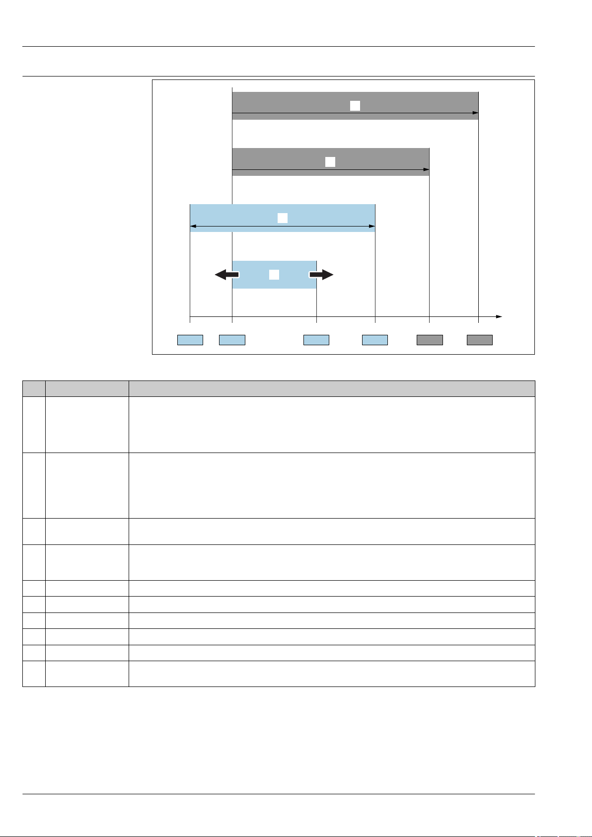
Item Term/abbreviation Explanation
1 OPL The OPL (over pressure limit = sensor overload limit) for the measuring device depends on the lowest-rated element,
with regard to pressure, of the selected components, i.e. the process connection has to be taken into consideration in
addition to the measuring cell. Also observe pressure-temperature dependency. For the relevant standards and
additional information, see the "Pressure specifications"→ 47 section.
The OPL may only be applied for a limited period of time.
2 MWP The MWP (maximum working pressure) for the sensors depends on the lowest-rated element, with regard to
pressure, of the selected components, i.e. the process connection has to be taken into consideration in addition to the
measuring cell. Also observe pressure-temperature dependency. For the relevant standards and additional
information, see the "Pressure specifications"→ 47 section.
The MWP may be applied at the device for an unlimited period.
The MWP can also be found on the nameplate.
3 Maximum sensor
measuring range
4 Calibrated/adjusted
span
p - Pressure
- LRL Lower range limit
- URL Upper range limit
- LRV Lower range value
- URV Upper range value
- TD (turn down) Turn down
Span between LRL and URL
This sensor measuring range is equivalent to the maximum calibratable/adjustable span.
Span between LRV and URV
Factory setting: 0 to URL
Other calibrated spans can be ordered as customized spans.
Example - see the following section.
6 Endress+Hauser
Page 7

Deltabar S PMD75, FMD77, FMD78
LRV
URLURV
LRL
1 = 2
3
Turn down calculation
1 Calibrated/adjusted span
2 Zero point-based span
3 URL sensor
Example
• Sensor:10 bar (150 psi)
• Upper range value (URL) = 10 bar (150 psi)
Turn down (TD):
A0029545
• Calibrated/adjusted span: 0 to 5 bar (0 to 75 psi)
• Lower range value (LRV) = 0 bar (0 psi)
• Upper range value (URV) = 5 bar (75 psi)
TD =
TD =
In this example, the TD is 2:1.
This span is based on the zero point.
Registered trademarks HART®
Registered trademark of the FieldComm Group, Austin, USA
PROFIBUS®
Registered trademark of the PROFIBUS User Organization, Karlsruhe, Germany
FOUNDATIONTMFieldbus
Registered trademark of the FieldComm Group, Austin, Texas, USA
URL
|URV - LRV|
10 bar (150 psi)
= 2
|5 bar (75 psi) - 0 bar (0 psi)|
Endress+Hauser 7
Page 8
Device selection
+ –
Deltabar S PMD75, FMD77, FMD78
Function and system design
A0023922
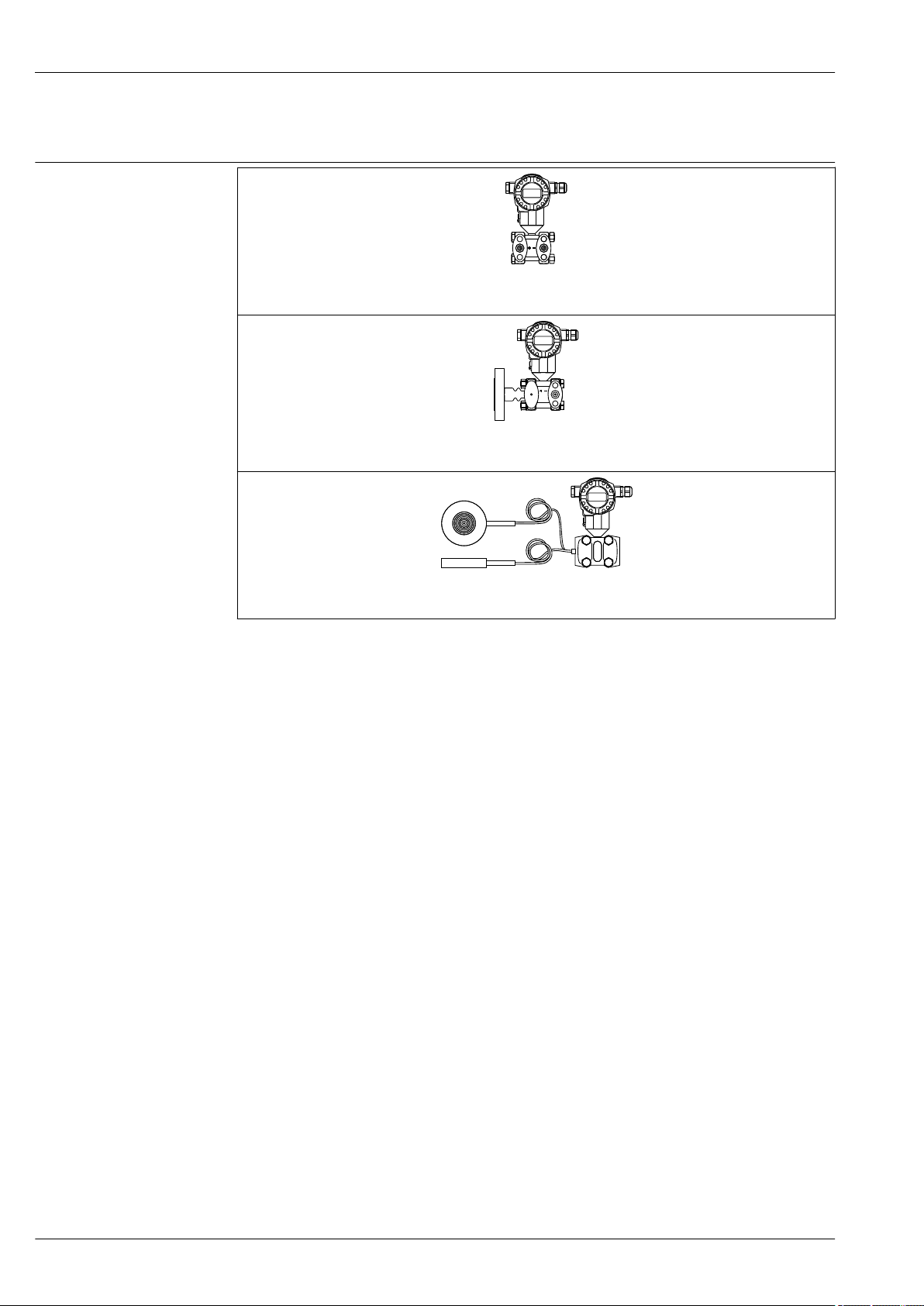
PMD75
A0023923
FMD77 with mounted diaphragm seal
FMD78 with capillary diaphragm seals
Field of application
PMD75:
• Flow
• Level
• Differential pressure
• Pressure
FMD77:
• Level
• Differential pressure
FMD78:
• Level
• Differential pressure
Process connections
PMD75:
• 1/4 – 18 NPT
• RC 1/4
FMD77 low-pressure side (–):
• 1/4 – 18 NPT
• RC 1/4
• Alternatively available with capillary and diaphragm seal
FMD77 high-pressure side (+):
• DN 50 – DN 100
• ASME NPS 2" – 4"
• JIS 80A – 100A
FMD78:
Wide range of diaphragm seals
A0023924
8 Endress+Hauser
Page 9

Deltabar S PMD75, FMD77, FMD78
Measuring ranges
• PMD75: from –10 to +10 mbar (-0.15 to +0.15 psi) to –40 to +40 bar (-600 to +600 psi)
As gauge or absolute pressure sensor: up to 250 bar (3750 psi)
• FMD77: from –100 to +100 mbar (-1.5 to +1.5 psi) to –16 bar to +16 bar (-240 to +240 psi)
• FMD78: from –100 to +100 mbar (-1.5 to +1.5 psi) to –40 to +40 bar (-600 to +600 psi)
OPL
PMD75:
on one side: up to 420 bar (6 300 psi)
on both sides: up to 630 bar (9 450 psi)
As gauge or absolute pressure sensor: up to 375 bar (5625 psi)
FMD77:
on one side: up to 160 bar (2 400 psi)
on both sides: up to 240 bar (3 600 psi)
FMD78:
on one side: up to 160 bar (2 400 psi)
on both sides: up to 240 bar (3 600 psi)
Process temperature range(temperature at process connection)
PMD75:
–40 to +85 °C (–40 to +185 °F)
FMD77:
–70 to +400 °C (–94 to +752 °F)
(depending on the filling oil)
FMD78:
–70 to +400 °C (–94 to +752 °F)
(depending on the filling oil)
Ambient temperature range
• Without LCD display: –50 to +85 °C (–58 to +185 °F)
• With LCD display: –20 to +70 °C (–4 to +158 °F)
(extended temperature application range–50 to +85 °C (–58 to +185 °F) with limitations in optical
properties, such as display speed and contrast)
• Separate housing –20 to +60 °C (–4 to +140 °F):
• Diaphragm seal systems depending on the version
Reference accuracy
• PMD75: up to ±0.035 % of the set span
• FMD77: up to ±0.075 % of the set span
• FMD78: up to ±0.075 % of the set span
Supply voltage
Supply voltage non-Ex
• 4 to 20 mA HART: 10.5 to 45 V DC
• PROFIBUS PA and FOUNDATION Fieldbus: 9 to 32 V DC
Supply voltage Ex ia
10.5 to 30 V DC
Output
4 to 20 mA with superimposed HART protocol, PROFIBUS PA or FOUNDATION Fieldbus
Options
• HistoROM®/M-DAT memory chip
• PMD75: with blind flange on LP side for gauge and absolute pressure measurement
Specialties
PMD75:
• p
up to 420 bar (6 300 psi)
stat
• Process isolating diaphragm: tantalum
Endress+Hauser 9
Page 10
FMD77:
p
2
p
1
1
2
3
44
h =
∆
p
ρ g
+
–
–
h
A
B
For extreme medium temperatures
FMD78:
Wide range of diaphragm seals
Measuring principle Metal process isolating diaphragm
1 Measuring element
2 Middle diaphragm
3 Filling oil
4 Process isolating diaphragm
The process isolating diaphragms are deflected on both sides by the acting pressures. A filling oil
transfers the pressure to a resistance bridge (semiconductor technology). The change in the bridge
output voltage, which depends on the differential pressure, is measured and processed
Advantages:
• Standard system pressures: 160 bar (2 400 psi) up to 420 bar (6 300 psi)
• High long-term stability
• Very high single-sided overload resistance
Deltabar S PMD75, FMD77, FMD78
A0023919
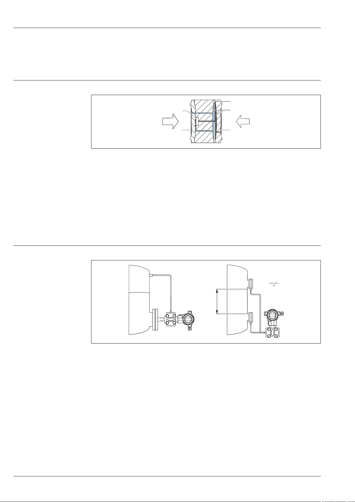
Product design Level measurement (level, volume and mass):
A Level measurement with FMD77
B Level measurement with FMD78
h Height (level)
Δp Differential pressure
ρ Density of the medium
g Gravitational constant
A0023921
10 Endress+Hauser
Page 11
Deltabar S PMD75, FMD77, FMD78
Q Q
Q ~ Q ~
∆ ∆p p
+ +
– –
p
1
p
1
p
2
p
2
A B
Your benefits
• Selection of the level operating mode which is optimum for your application in the device software
• Volume and mass measurements in any container shapes by means of a freely programmable
characteristic curve
• Choice of diverse level units with automatic unit conversion
• A customized unit can be specified.
• Has a wide range of uses, e.g.
– for level measurement in vessels with pressure overlay
– in the event of foam formation
– in containers with agitators or screen fittings
– in the event of liquid gases
– for standard level measurement
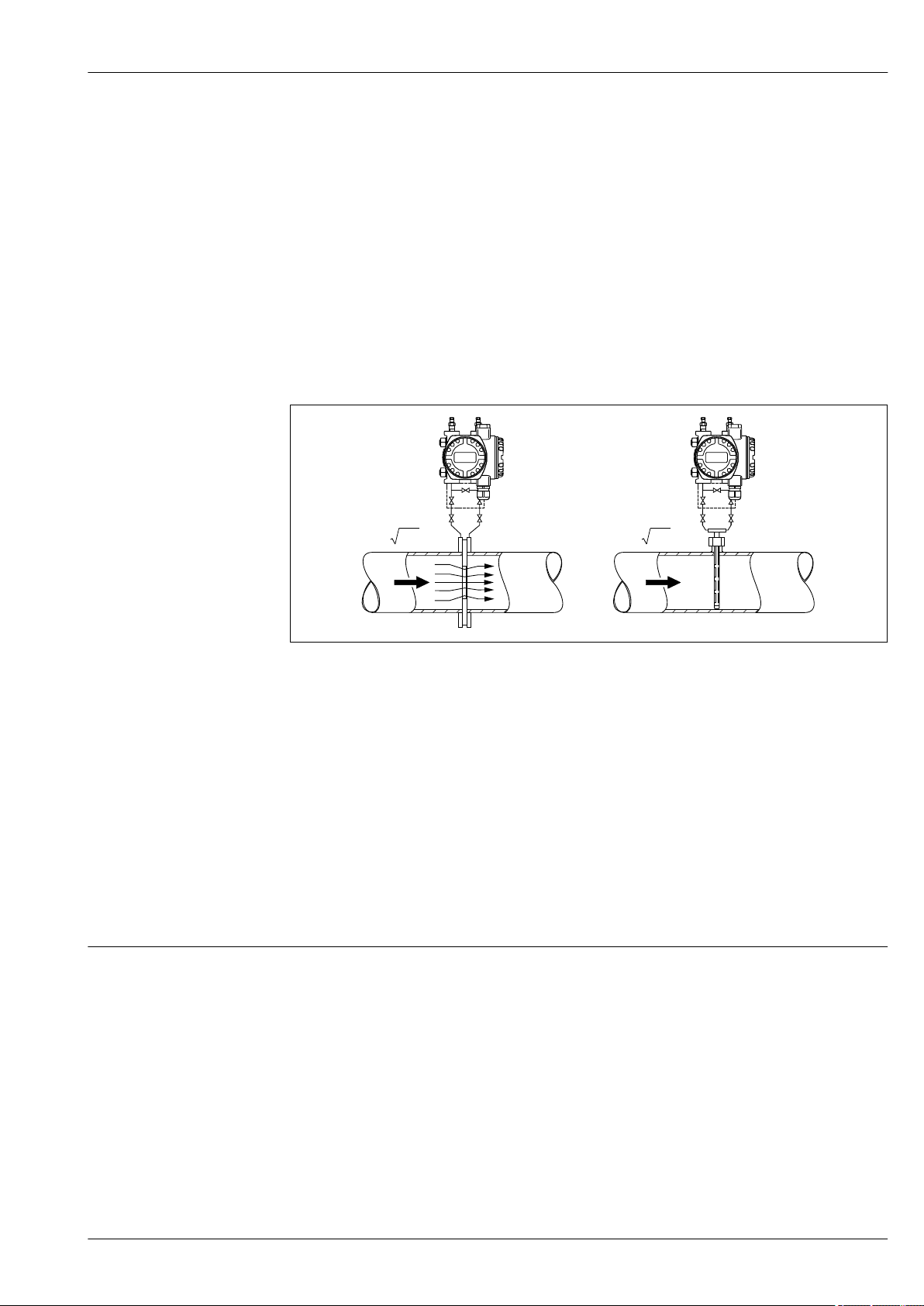
Flow measurement
Flow measurement with Deltabar S and primary device:
Communication protocol
A Orifice plate
B Pitot tube
Q Flow
Δp Differential pressure, Δp = p1 – p
2
Your benefits
• Choice of four flow modes of operation: volume flow, corrected volume flow (European norm
conditions), standard volume flow (American standard conditions) and mass flow
• Choice of diverse flow units with automatic unit conversion
• A customized unit can be specified.
• Low flow cut off: when activated, this function suppresses small flows which can lead to large
fluctuations in the measured value.
• Contains two totalizers as standard. One totalizer can be reset to zero.
• The totalizing mode and unit can be individually set for each totalizer. This allows independent
daily and annual quantity totalizing.
• 4 to 20 mA with HART communication protocol
• PROFIBUS PA
– The Endress+Hauser devices meet the requirements of the FISCO model.
– Due to a low current consumption of 13 mA ± 1 mA, the following number of devices can be
operated on one bus segment if installing as per FISCO: up to 7 devices for Ex ia, CSA IS and FM
IS applications or up to 27 devices for all other applications e.g. in non-hazardous areas, Ex nA
etc. Further information on PROFIBUS PA can be found in Operating Instructions BA00034S
"PROFIBUS DP/PA: Guidelines for planning and commissioning" and in the PNO Guideline.
• FOUNDATION Fieldbus
– The Endress+Hauser devices meet the requirements of the FISCO model.
– Due to a low current consumption of 15.5 mA ± 1 mA, the following number of devices can be
operated on one bus segment if installing as per FISCO: up to 6 devices for Ex ia, CSA IS and FM
IS applications or up to 24 devices for all other applications e.g. in non-hazardous areas, Ex nA
etc. Further information on FOUNDATION Fieldbus, such as requirements for bus system
components, can be found in Operating Instructions BA00013S "FOUNDATION Fieldbus
Overview".
A0023920
Endress+Hauser 11
Page 12
Input
Measured variable Measured process variables
Differential pressure, pressure
Calculated process variables
• Flow rate (volume flow or mass flow)
• Absolute pressure, gauge pressure
• Level (level, volume or mass)
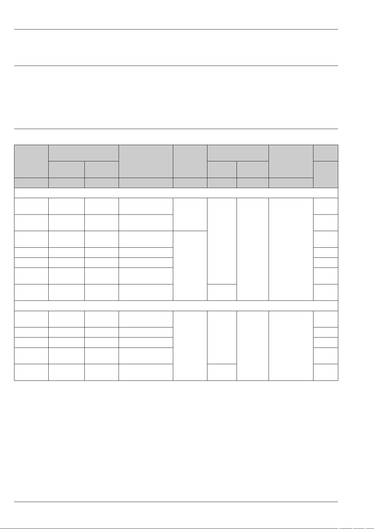
Measuring range
Deltabar S PMD75, FMD77, FMD78
Sensor Maximum sensor measuring
range
lower (LRL) upper (URL) on one side on both
[mbar (psi)] [mbar (psi)] [mbar (psi)] [mbar (psi)] [bar (psi)] [bar (psi)] [bar (psi)] [mbar
Smallest calibratable
1)
span
MWP OPL remains stable
for a minimum of
sides
operating
pressure
abs
2)
(psi
abs
Option
PN 160
)]
FMD77, FMD78, PMD75: Option PN 160 / 16 MPa / 2400 psi
10 (0.15)
–10 (-0.15) +10 (+0.15) 0.25 (0.00375) 160 (2400) 160 (2400) 240 (3600)
7B
(PMD75 only)
30 (0.45)
–30 (-0.45) +30 (+0.45) 0.3 (0.0045) 7C
(PMD75 only)
100 (1.5) –100 (-1.5) +100 (+1.5) 1/5
(0.015/0.075)
4)
160 (2400)
500 (7.5) –500 (-7.5) +500 (+7.5) 5 (0.075) 7F
5)
7D
0.1 (0.0015)
3000 (45) –3000 (-45) +3000 (+45) 30 (0.45) 7H
16000 (240) –16000
(-240)
40000 (600) –40000
(-600)
+16000
(+240)
+40000
(+600)
160 (2.4) 7L
400 (6) "+" side
6)
:
7M
160 (2400)
PMD75: Option PN 420 / 42 MPa / 6300 psi
100 (1.5) –100 (-1.5) +100 (+1.5) 1/5
(0.015/0.075)
4)
420 (6300)
5)
420 (6300) 630 (9450)
8D
500 (7.5) –500 (-7.5) +500 (+7.5) 5 (0.075) 8F
3000 (45) –3000 (-45) +3000 (+45) 30 (0.45) 8H
16000 (240) –16000
(-240)
40000 (600) –40000
(-600)
+16000
(+240)
+40000
(+600)
160 (2.4) 8L
400 (6) "+" side
6)
:
420 (6300)
0.1 (0.0015)
8M
3)
1) Turn down > 100:1 on request
2) The minimum operating pressure indicated in the table applies to silicone oil under reference operating conditions. Min. operating pressure at
85 °C (185 °F) for silicone oil: up to 10 mbar
(0.15 psi
abs
). FMD77 and FMD78: Min. operating pressure: 50 mbar
abs
(0.75 psi
abs
; observe also
abs)
the pressure and temperature application limits of the selected filling oil → 97. For vacuum applications, follow the installation
instructions→ 102.
3) Product Configurator, order code for "Nominal range; PN"
4) Smallest calibratable span for the PMD75: 1 mbar (0.015 psi); Smallest calibratable span for the FMD77 and FMD78: 5 mbar (0.075 psi)
5) All PMD75 process connections are CRN-approved. If O-rings are used, the MWP is 315 bar (4 725 psi); if PTFE and CU seals are used, the MWP
is 120 bar (1 800 psi).
6) "–" side: 100 bar (1 500 psi)
12 Endress+Hauser
Page 13

Deltabar S PMD75, FMD77, FMD78
Sensor Maximum sensor measuring
range
lower (LRL) upper (URL) on one side on both
Smallest
calibratable span
MWP OPL remains stable for a
minimum of
operating pressure
Option
1)
sides
bar (psi) bar (psi) bar (psi) bar (psi) bar (psi) bar (psi) mbar
abs
(psi
abs
)
PMD75: optionally available as a gauge or absolute pressure sensor
160 (2400) rel -1 (-15) 160 (2400) 40 (600) 160 (2400) 240 (3600) -
160 (2400) abs 0 160 (2400) 4 (60) 160 (2400) 240 (3600) -
250 (3750) rel -1 (-15) 250 (3750) 40 (600) 250 (3750) 375 (5625) -
250 (3750) abs 0 250 (3750) 4 (60) 250 (3750) 375 (5625) -
3)
3)
3)
3)
10 7Q
10 7V
10 7R
10 7W
1) The minimum operating pressure indicated in the table applies to silicone oil under reference operating conditions. Min. operating pressure at
85 °C (185 °F) for silicone oil: up to 10 mbar
(0.15 psi
abs
abs
).
2) Product Configurator, order code for "Nominal range; PN"
3) Available only with blind flange on LP side.
2)
Endress+Hauser 13
Page 14
Output
on on
off off
damp.
damp.
Display Display
Sensor Sensor
HART HART
R R
FIELD COMMUNICATION PROTOCOL FIELD COMMUNICATION PROTOCOL
SW /min
SW /min
E
+
–
E
+
–
Deltabar S PMD75, FMD77, FMD78
Output Signal
• 4 to 20 mA with superimposed digital communication protocol HART, 2-wire
• Digital communication signal PROFIBUS PA (Profile 3.0), 2-wire
– Signal coding: Manchester Bus Powered (MBP): Manchester II
– Transmission rate: 31.25 KBit/s voltage mode
• Digital communication signal FOUNDATION Fieldbus, 2-wire
– Signal coding: Manchester Bus Powered (MBP): Manchester II
– Transmission rate: 31.25 KBit/s voltage mode
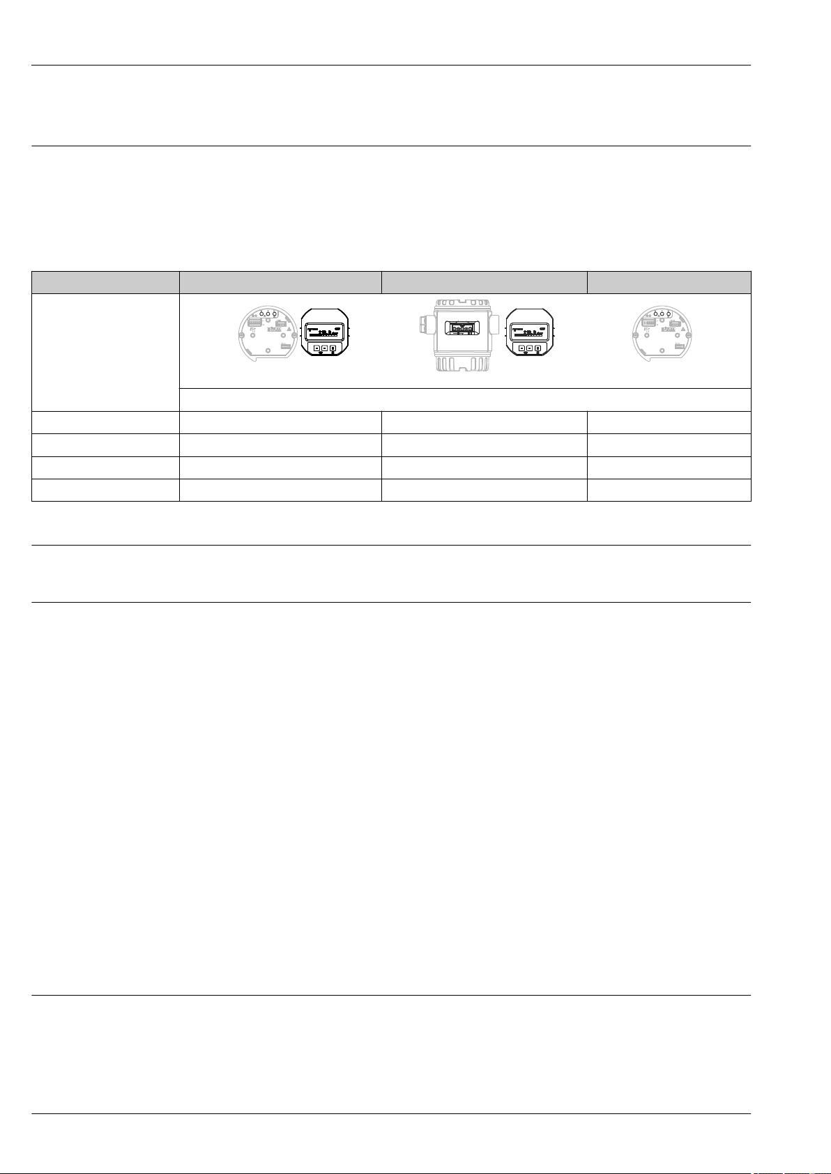
Output Internal + LCD External + LCD Internal
1)
Option
4 to 20mA HART B A C
4 to 20mA HART, Li=0 E D F
PROFIBUS PA N M O
FOUNDATION Fieldbus Q P R
1) Product Configurator, order code for "Display, operation: "
Signal range 4 to 20 mA
3.8 mA to 20.5 mA
A0021280
Signal on alarm 4 to 20 mA HART
As per NAMUR NE43.
• Max. alarm: can be set from 21 to 23 mA (factory setting: 22 mA)
• Hold measured value: last measured value is held
• Min. alarm: 3.6 mA
PROFIBUS PA
As per NAMUR NE43.
Can be set in the Analog Input Block.
Options:
• Last Valid Out Value (factory setting)
• Fail Safe Value
• Status bad
FOUNDATION Fieldbus
As per NAMUR NE43.
Can be set in the Analog Input Block.
Options:
• Last Good Value
• Fail Safe Value (factory setting)
• Wrong Value
Load 4 to 20 mA HART
In order to guarantee sufficient terminal voltage in two-wire devices, a maximum load resistance R
(including line resistance) must not be exceeded depending on the supply voltage U0 of the supply
unit. In the following load diagrams, observe the position of the jumper and the explosion protection:
14 Endress+Hauser
Page 15

Deltabar S PMD75, FMD77, FMD78
U – 11.5 V
23 mA
[ ]W
30
20
11.5
40 45
1239
1456
804
369
Test
£
B
U – 10.5 V
R
L
max
23 mA
£
30
20
10.5
U U
[V] [V]
40 45
1282
1500
847
413
[ ]W
R
L
max
Test
3
A
1
2
1
2
R
L
max
3
R
L
max
I
63 %
100 %
t
t1t
2
90 %
t
3
A Jumper for 4 to 20 mA test signal set to "Non-test" position
B Jumper for 4 to 20 mA test signal set to "Test" position
1 Power supply 10.5 (11.5) to 30 V DC for 1/2 G Ex ia, 1GD Ex ia, 1/2 GD Ex ia, FM IS, CSA IS, IECEx ia, NEPSI
2 Power supply 10.5 (11.5) to 45 V DC for devices for non-hazardous areas, 1/2 D, 1/3 D, 2 G Ex d, 3 G Ex nA,
3 R
U Supply voltage
Ex ia
FM XP, FM DIP, FM NI, CSA XP, CSA dust ignition-proof, NEPSI Ex d
maximum load resistance
Lmax
A0019988
Dead time, time constant
When operating via a handheld terminal or via a PC with an operating program, a minimum
communication resistance of 250 Ω must be taken into account.
Presentation of the dead time and the time constant:
A0019786
Endress+Hauser 15
Page 16

Deltabar S PMD75, FMD77, FMD78
Dynamic behavior, current output
Type Measuring cell Dead time (t1) [ms] Time constant T63 (t2) [ms] Time constant T90 (t3) [ms]
PMD75 max. • 10 mbar (0.15 psi)
• 30 mbar (0.45 psi)
• 100 mbar (1.5 psi)
• 500 mbar (7.5 psi)
• 3 bar (45 psi)
• 16 bar (240 psi)
• 40 bar (600 psi)
• 160 bar (2 400 psi)
• 250 bar (3 750 psi)
FMD77,
FMD78
max. Dependent on the diaphragm seal
Dynamic behavior Digital output (HART electronics)
A typical burst rate of 300 ms results in the following behavior:
45 • 450
• 450
• 60
• 45
• 40
• 60
• 60
50 40 90
• 1040
• 1040
• 138
• 104
• 92
• 138
• 138
Type Measuring cell Dead time (t1) [ms] Dead time (t1) [ms] +
Time constant T63 (t2) [ms]
PMD75 min. • 10 mbar (0.15 psi)
• 30 mbar (0.45 psi)
• 100 mbar (1.5 psi)
• 500 mbar (7.5 psi)
• 3 bar (45 psi)
• 16 bar (240 psi)
• 40 bar (600 psi)
• 160 bar (2 400 psi)
• 250 bar (3 750 psi)
max. • 10 mbar (0.15 psi)
• 30 mbar (0.45 psi)
• 100 mbar (1.5 psi)
• 500 mbar (7.5 psi)
• 3 bar (45 psi)
• 16 bar (240 psi)
• 40 bar (600 psi)
• 160 bar (2 400 psi)
• 250 bar (3 750 psi)
FMD77,
FMD78
max. Dependent on the diaphragm seal
205 • 655
• 655
• 265
• 250
• 245
• 265
• 265
• 295
• 295
1005 • 1455
• 1455
• 1065
• 1050
• 1045
• 1065
• 1065
• 1095
• 1095
Dead time (t1) [ms] +
Time constant T90 (t3) [ms]
• 1200
• 1200
• 298
• 264
• 252
• 298
• 298
• 300
• 300
• 2000
• 2000
• 1098
• 1064
• 1052
• 1098
• 1098
• 1100
• 1100
Reading cycle
• Acyclic: max. 3/s, typically 1/s (depending on command # and number of preambles)
• Cyclic (burst): max. 3/s, typically 2/s
The device commands the BURST MODE functionality for cyclical value transmission via the HART
communication protocol.
Cycle time (update time)
Cyclic (burst): min. 300 ms
Response time
• Acyclic: min. 330 ms, typically 590 ms (depending on command # and number of preambles)
• Cyclic (burst): min. 160 ms, typically 350 ms (depending on command # and number of
preambles)
16 Endress+Hauser
Page 17

Deltabar S PMD75, FMD77, FMD78
Dynamic behavior
A typical PLC cycle time of 1 s results in the following behavior:
PROFIBUS PA
Type Measuring cell Dead time (t1) [ms] Dead time (t1) [ms] +
Time constant T63 (t2) [ms]
PMD75 min. • 10 mbar (0.15 psi)
• 30 mbar (0.45 psi)
• 100 mbar (1.5 psi)
• 500 mbar (7.5 psi)
• 3 bar (45 psi)
• 16 bar (240 psi)
• 40 bar (600 psi)
max. • 10 mbar (0.15 psi)
• 30 mbar (0.45 psi)
• 100 mbar (1.5 psi)
• 500 mbar (7.5 psi)
• 3 bar (45 psi)
• 16 bar (240 psi)
• 40 bar (600 psi)
FMD77,
FMD78
max. Dependent on the diaphragm seal
80 • 530
• 530
• 140
• 125
• 120
• 140
• 140
1280 • 1730
• 1730
• 1340
• 1325
• 1320
• 1340
• 1340
Reading cycle (PLC)
• Acyclic: Typically 25/s
• Cyclic: Typically 30/s (depending on the number and type of the function blocks used in the
closed-control loop)
Dead time (t1) [ms] +
Time constant T90 (t3) [ms]
• 1075
• 1075
• 173
• 139
• 127
• 173
• 173
• 2275
• 2275
• 1373
• 1339
• 1327
• 1373
• 1373
Cycle time (update time)
min. 200 ms
The cycle time in a bus segment in cyclic data communication depends on the number of devices, on
the segment coupler used and on the internal PLC cycle time. A new measured value can be
determined up to five times a second.
Response time
• Acyclic: Approx. 60 ms to 70 ms (depending on Min. Slave Interval)
• Cyclic: Approx. 10 ms to 13 ms (depending on Min. Slave Interval)
Dynamic behavior FOUNDATION Fieldbus
Type Measuring cell Dead time (t1) [ms] Dead time (t1) [ms] +
PMD75 min. • 10 mbar (0.15 psi)
• 30 mbar (0.45 psi)
• 100 mbar (1.5 psi)
• 500 mbar (7.5 psi)
• 3 bar (45 psi)
• 16 bar (240 psi)
• 40 bar (600 psi)
max. • 10 mbar (0.15 psi)
• 30 mbar (0.45 psi)
• 100 mbar (1.5 psi)
• 500 mbar (7.5 psi)
• 3 bar (45 psi)
• 16 bar (240 psi)
• 40 bar (600 psi)
FMD77,
FMD78
max. Dependent on the diaphragm seal
A typical configuration for the macro cycle time (host system) of 1 s results in the following
behavior:
Time constant T63 (t2) [ms]
90 • 540
• 540
• 150
• 135
• 130
• 150
• 150
1090 • 1540
• 1540
• 1150
• 1135
• 1130
• 1150
• 1150
Dead time (t1) [ms] +
Time constant T90 (t3) [ms]
• 1085
• 1085
• 183
• 149
• 137
• 183
• 183
• 2085
• 2085
• 1183
• 1149
• 1137
• 1183
• 1183
Endress+Hauser 17
Page 18

Deltabar S PMD75, FMD77, FMD78
Reading cycle
• Acyclic: Typically 10/s
• Cyclic: max. 10/s (dependent on the number and type of function blocks used in a closed-control
loop)
Cycle time (update time)
Cyclic: Min. 100 ms
Response time
• Acyclic: Typically 100 ms (for standard bus parameter settings)
• Cyclic: max. 20 ms (for standard bus parameter settings)
Damping
Alarm current
Firmware version
A damping affects all outputs (output signal, display):
• via local display, handheld terminal or PC with operating program, continuous from 0 to 999 s
• Also for HART and PROFIBUS PA: Via DIP switch on the electronic insert,
switch position "on" = set value and "off"
• Factory setting: 2 s
Designation Option
Min alarm current J
HART burst mode PV J
Min alarm current + HART burst mode PV J
1) Product Configurator, "Additional options 1" and "Additional options 2" ordering feature
Designation Option
02.20.zz, HART 7, DevRev22 72
02.11.zz, HART 5, DevRev21 73
04.00.zz, FF, DevRev07 74
04.01.zz, PROFIBUS PA, DevRev03 75
02.10.zz, HART 5, DevRev21 76
03.00.zz, FF, DevRev06 77
04.00.zz, PROFIBUS PA 78
02.30.zz, HART 7 In preparation
1)
1)
1) Product Configurator, order code for "Firmware version"
HART protocol-specific data
Manufacturer ID 17 (11 hex)
Device type code 23 (17 hex)
Device revision • 21 (15 hex) - SW version 02.1y.zz - HART specification 5
• 22 (16 hex) - SW version 02.2y.zz - HART specification 7
HART specification • 5
• 7
DD revision • 4 (Russian in language selection) for device revision 21
• 3 (Dutch in language selection) for device revision 21
• 1 for device revision 22
Device description files (DTM, DD) Information and files at:
• www.endress.com
• www.fieldcommgroup.org
HART load Min. 250 Ω
18 Endress+Hauser
Page 19

Deltabar S PMD75, FMD77, FMD78
HART device variables The measured values are assigned to the device variables as follows:
Supported functions • Burst mode
Measured values for PV (primary variable)
• Pressure
• Flow
• Level
• Tank content
Measured values for SV, TV (second and third variable)
• Pressure
• Totalizer
Measured values for QV (fourth variable)
Temperature
• Additional transmitter status
• Device locking
• Alternative operating modes
PROFIBUS PA protocolspecific data
Manufacturer ID 17 (11 hex)
Identification number 1542 hex
Profile version 3.0
• SW version 03.00.zz
• SW version 04.00.zz
3.02
SW version 04.01.zz ( device revision 3)
Compatibility with SW version 03.00.zz and higher.
GSD revision • 4 (SW version 3.00.zz and 4.00.zz)
• 5 (device revision 3)
DD revision • 1 (SW version 3.00.zz and 4.00.zz)
• 1 (device revision 3)
GSD file Information and files at:
DD files
Output values Measured value for PV (via Analog Input Function Block)
Input values Input value sent from PLC, can be shown on display
Supported functions • Identification & maintenance Simplest device identifier on the
• www.endress.com
• www.profibus.org
• Pressure
• Level
• Flow
• Tank content
Measured value for SV
• Pressure
• Temperature
Measured value for QV
Totalizer
control system and nameplate
• Condensed status (only with Profile Version 3.02)
• Automatic ID number adjustment and switchable to the following ID
numbers (only with Profile Version 3.02):
– 9700: Profile-specific transmitter identification number with the
"Classic" or "Condensed" status".
– 1504: Compatibility mode for the old Deltabar S generation
(FMD230, FMD630, FMD633, PMD230, PMD235).
– 1542: Identification number of the new Deltabar S generation
( FMD77, FMD78, PMD75).
• Device locking: The device can be locked by hardware or software.
FOUNDATION Fieldbus protocol-specific data
Manufacturer ID 452B48 hex
Device type 1009 hex
Device revision • 6 - SW version 03.00.zz
• 7 - SW version 04.00.zz (FF-912)
Endress+Hauser 19
Page 20
Deltabar S PMD75, FMD77, FMD78
DD revision • 3 (device revision 6)
• 2 (device revision 7)
CFF revision • 4 (device revision 6)
• 1 (device revision 7)
DD files Information and files at:
CFF files
Device tester version (ITK version) • 5.0 (device revision 6)
Number of ITK test campaign • IT054700 (Device Revision 6)
Link Master (LAS) capable Yes
Choice of "Link Master" and "Basic
Device"
Node address Factory setting: 247 (F7 hex)
Supported functions Field diagnostics profile (only with FF912)
Number of VCRs • 44 (device revision 6)
Number of link objects in VFD 50
• www.endress.com
• www.fieldcommgroup.org
• 6.01 (device revision 7)
• IT085400 (Device Revision 7)
Yes, factory setting is Basic Device
The following methods are supported:
• Restart
• Configure error as warning or alarm
• HistoROM
• Peakhold
• Alarm info
• Sensor trim
• 24 (device revision 7)
Virtual communication references (VCRs)
Device revision 6 Device revision 7
Permanent entries 44 1
Client VCRs 0 0
Server VCRs 5 10
Source VCRs 8 43
Sink VCRs 0 0
Subscriber VCRs 12 43
Publisher VCRs 19 43
Link settings
Device revision 6 Device revision 7
Slot time 4 4
Min. Inter PDU delay 12 10
Max. response delay 10 10
20 Endress+Hauser
Page 21

Deltabar S PMD75, FMD77, FMD78
Transducer Blocks
Block Content Output values
TRD1 Block Contains all parameters related to
Service Block Contains service information • Pressure after damping (channel 3)
Dp Flow Block Contains flow and totalizer
Diagnostic Block Contains diagnostic information Error code via DI channels (channel 0 to 16)
Display Block Contains parameters to configure
Function blocks
the measurement
parameter
the onsite display
• Pressure, flow or level (channel 1)
• Process temperature (channel 2)
• Pressure peakhold indicator (channel 4)
• Counter for max. pressure transgressions (channel
5)
Totalizer 1 (channel 6)
No output values
Block Content Number
blocks
Resource Block This block contains all the data that uniquely identifies the device; it
is an electronic version of a nameplate for the device.
Analog Input
Block 1
Analog Input
Block 2
Analog Input
Block 3
Digital Input
Block
Digital Output
Block
PID Block This block is used as a proportional-integral-derivative controller and
Arithmetic
Block
Input Selector
Block
Signal
Characterizer
Block
The AI Block receives the measuring data from the Sensor Block,
(selectable via a channel number) and makes the data available to
other function blocks at its output. Enhancement: Digital outputs for
process alarms, fail safe mode
This block contains the discrete data of the Diagnose Block (selectable
via a channel number 0 to 16) and provides them for other blocks at
the output.
This block converts the discrete input and thus initiates an action
(selectable via a channel number) in the DP Flow Block or in the
Service Block. Channel 1 resets the counter for max. pressure
transgressions.
can be used universally for closed-loop-control in the field. It enables
cascade mode and feedforward control. Input IN can be indicated on
the display. The selection is performed in the Display Block
(DISPLAY_MAIN_LINE_CONTENT).
This block is designed to permit simple use of popular measurement
math functions. The user does not have to know how to write
equations. The math algorithm is selected by name, chosen by the
user for the function to be performed.
The Input Selector Block facilitates the selection of up to four inputs
and generates an output based on the configured action. This block
normally receives its inputs from AI Blocks. The block performs
maximum, minimum, average and ‘first good’ signal selection. Inputs
IN1 to IN4 can be indicated on the display. The selection is performed
in the Display Block (DISPLAY_MAIN_LINE_CONTENT).
The Signal Characterizer Block has two sections, each with an output
that is a non-linear function of the respective input. The non-linear
function is generated by a single look-up table with 21 arbitrary x-y
pairs.
1 enhanced enhanced
3 45 ms 45 ms
1 40 ms 30 ms standard enhanced
1 60 ms 40 ms standard enhanced
1 120 ms 70 ms standard enhanced
1 50 ms 40 ms standard enhanced
1 35 ms 35 ms standard enhanced
1 30 ms 40 ms standard enhanced
Execution time Functionality
Device
Revision 6
Device
Revision 7
(without
trend and
alarm
reports)
Device
Revision 6
enhanced enhanced
Device
Revision 7
Endress+Hauser 21
Page 22

Deltabar S PMD75, FMD77, FMD78
Block Content Number
blocks
Integrator Block The Integrator Block integrates a variable as a function of the time or
accumulates the counts from a Pulse Input Block. The block can be
used as a totalizer that counts up until a reset, or as a batch totalizer
whereby the integrated value is compared against a target value
generated before or during the control routine and generates a binary
signal when the target value is reached.
Analog Alarm
Block
This block contains all process alarm conditions (working like a
comparator) and represents them at the output.
1 35 ms 40 ms standard enhanced
1 35 ms 35 ms standard enhanced
Additional function block information:
Instantiatable function blocks YES YES
Number of additional instantiatable function blocks 9 4
Execution time Functionality
Device
Revision 6
Device
Revision 7
Device
Revision 6
Device
Revision 7
22 Endress+Hauser
Page 23
Deltabar S PMD75, FMD77, FMD78
4... 20mA
Test
Test
Test
4... 20mA Test
1
8
6
7
2
3
4
5
1
4
5
2
3
Power supply
WARNING
L
Electrical safety is compromised by an incorrect connection!
When using the measuring device in hazardous areas, the relevant national standards and
‣
regulations as well as the Safety Instructions or Installation or Control Drawings must also be
observed.→ 113.
All explosion protection data are given in separate documentation which is available upon
‣
request. The Ex documentation is supplied as standard with all Ex devices→ 113.
Devices with integrated overvoltage protection must be grounded→ 26.
‣
Protective circuits against reverse polarity, HF influences and overvoltage peaks are integrated.
‣
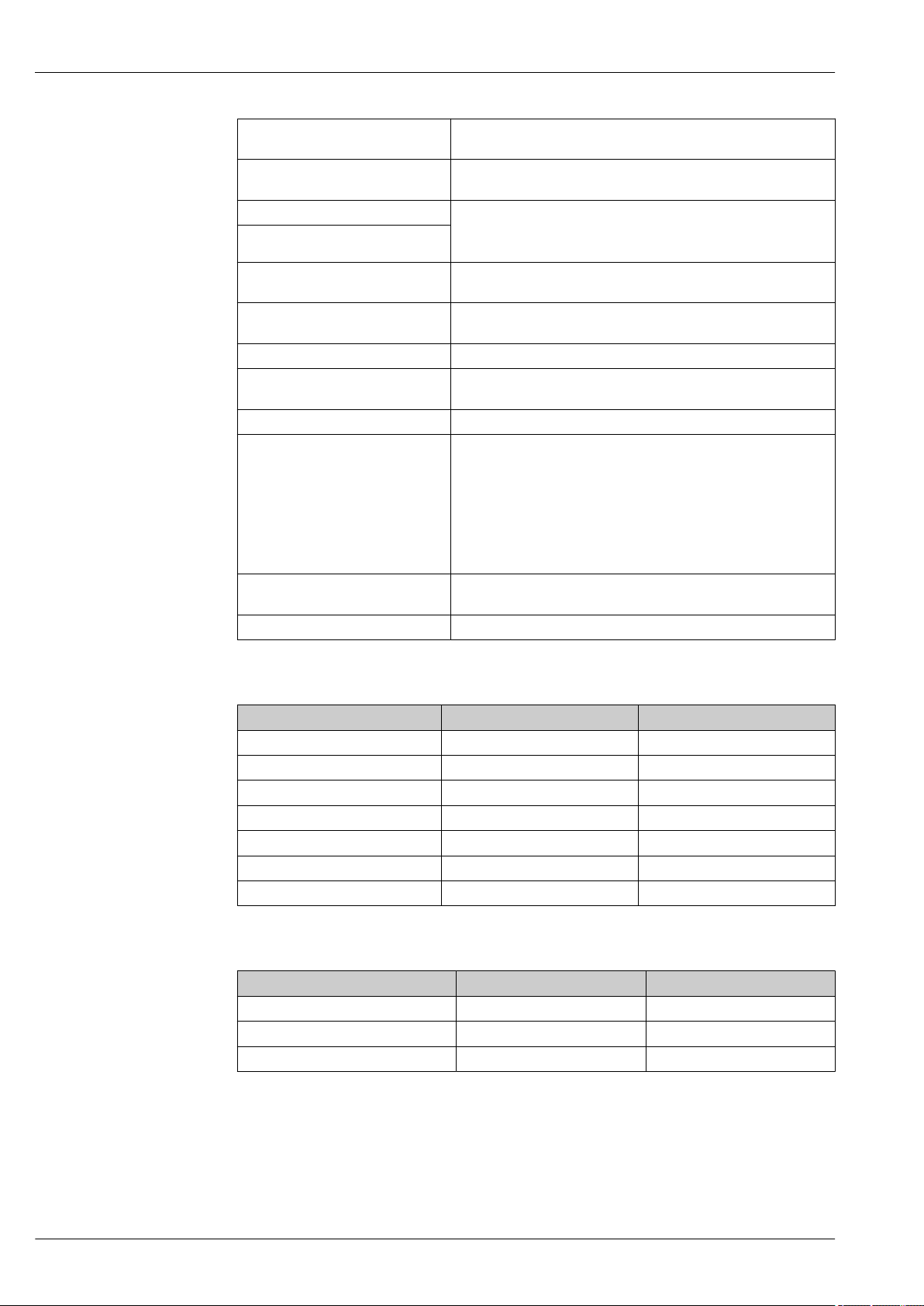
Terminal assignment 4 to 20 mA HART
A0019989
1 Housing
2 Supply voltage
3 4 to 20 mA
4 Devices with integrated overvoltage protection are labeled "OVP" (overvoltage protection) here.
5 External ground terminal
6 4 to 20 mA test signal between positive and test terminal
7 Internal ground terminal
8 Jumper for 4 to 20 mA test signal
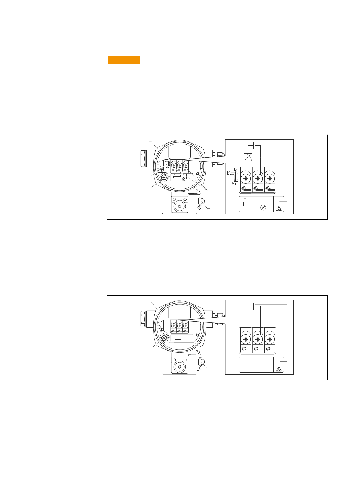
PROFIBUS PA and FOUNDATION Fieldbus
A0020158
1 Housing
2 Supply voltage
3 Devices with integrated overvoltage protection are labeled "OVP" (overvoltage protection) here.
4 External ground terminal
5 Internal ground terminal
Endress+Hauser 23
Page 24
Supply voltage 4 to 20 mA HART
Test
Test
Deltabar S PMD75, FMD77, FMD78
Electronic version Jumper for 4 to 20 mA test signal in
"Test" position (delivery status)
Version for nonhazardous area
Intrinsically safe 11.5 to 30 V DC 10.5 to 30 V DC
• Other types of
protection
• Devices without
certificate
11.5 to 45 V DC 10.5 to 45 V DC
11.5 to 45 V DC
(versions with 35 V DC plug-in
connection)
Jumper for 4 to 20 mA test signal in
"Non-test" position
10.5 to 45 V DC
(versions with 35 V DC plug-in
connection)
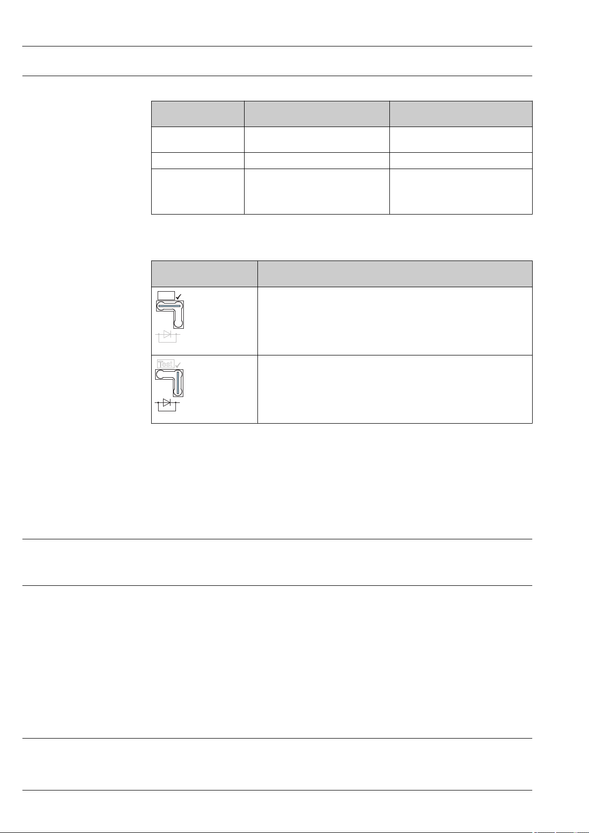
Measuring a 4 to 20 mA test signal
Jumper position for test
signal
Description
• Measurement of 4 to 20 mA test signal via the positive and test terminal:
Possible. (Thus, the output current can be measured without interruption via
the diode.)
• Delivery status
• Minimum supply voltage: 11.5 V DC
A0019992
• Measurement of 4 to 20 mA test signal via positive and test terminal: Not
possible.
• Minimum supply voltage: 10.5 V DC
PROFIBUS PA
• Version for non-hazardous areas: 9 to 32 V DC
• Ex ia: 10.5 to 30 V DC
FOUNDATION Fieldbus
• Version for non-hazardous areas: 9 to 32 V DC
• Ex ia: 10.5 to 30 V DC
Current consumption
• PROFIBUS PA: 13 mA ±1 mA, switch-on current corresponds to IEC 61158-2, Clause 21
• FOUNDATION Fieldbus: 15.5 mA ±1 mA, switch-on current corresponds to IEC 61158-2, Clause
21
Electrical connection PROFIBUS PA
The digital communication signal is transmitted to the bus via a two-wire connection. The bus also
provides the power supply. For further information on the network structure and grounding, and for
further bus system components such as bus cables, see the relevant documentation, e.g. Operating
Instructions BA00034S "PROFIBUS DP/PA: Guidelines for planning and commissioning" and the
PNO Guideline.
FOUNDATION Fieldbus
The digital communication signal is transmitted to the bus via a two-wire connection. The bus also
provides the power supply. For further information on the network structure and grounding and for
further bus system components such as bus cables, see the relevant documentation, e.g. Operating
Instructions BA00013S "FOUNDATION Fieldbus Overview" and the FOUNDATION Fieldbus Guideline.
A0019993
Terminals
• Supply voltage and internal ground terminal: 0.5 to 2.5 mm2 (20 to 14 AWG)
• External ground terminal: 0.5 to 4 mm2 (20 to 12 AWG)
24 Endress+Hauser
Page 25
Deltabar S PMD75, FMD77, FMD78
Han7D
–
+
+ –
–
+
1
5
4
6
7
8
2
3
A B
2
1
3
4
Cable entries
Approval Cable gland Clamping area
Standard, II 1/2 G Ex ia, IS Plastic M20x1.5 5 to 10 mm (0.2 to 0.39 in)
ATEX II 1/2 D, II 1/3 D, II 1/2 GD Ex ia,
II 1 GD Ex ia, II 3 G Ex nA
For additional technical data, see section on housing → 49
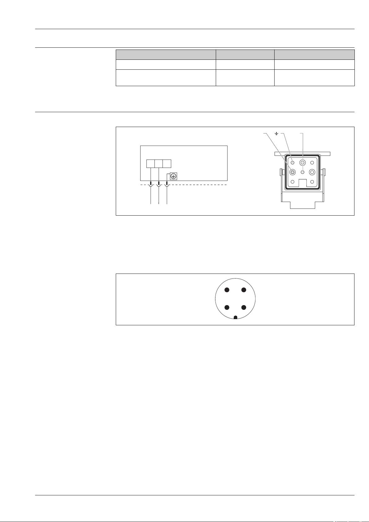
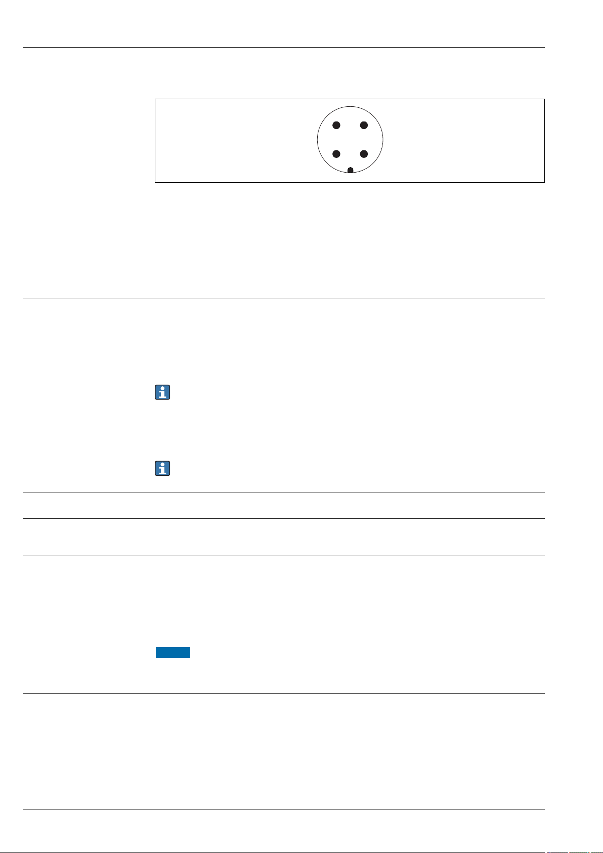
Device plug Devices with Harting plug Han7D
A Electrical connection for devices with Harting plug Han7D
B View of the plug-in connection on the device
Metal M20x1.5 (Ex e) 7 to 10.5 mm (0.28 to 0.41 in)
A0019990
Material: CuZn, gold-plated plug-in jack and plug
Devices with M12 plug
1 Signal +
2 Not assigned
3 Signal –
4 Ground
Endress+Hauser offers the following accessories for devices with an M12 plug:
Plug-in jack M 12x1, straight
• Material: Body PA; coupling nut CuZn, nickel-plated
• Degree of protection (fully locked): IP67
• Order number: 52006263
Plug-in jack M 12x1, elbowed
• Material: Body PBT/PA; coupling nut GD-Zn, nickel-plated
• Degree of protection (fully locked): IP67
• Order number: 71114212
Cable 4x0.34 mm2 (20 AWG) with M12 socket, elbowed, screw plug, length 5 m (16 ft)
• Material: Body PUR; coupling nut CuSn/Ni; cable PVC
• Degree of protection (fully locked): IP67
• Order number: 52010285
A0011175
Endress+Hauser 25
Page 26
Devices with 7/8" plug
4
2
3
1
1 Signal –
2 Signal +
3 Not assigned
4 Shielding
External thread: 7/8 - 16 UNC
• Material: 316L (1.4401)
• Degree of protection: IP68
Cable specification HART
• Endress+Hauser recommends using shielded, twisted-pair two-wire cables.
• Cable outer diameter: 5 to 9 mm (0.2 to 0.35 in) depending on the cable entry used → 25
Deltabar S PMD75, FMD77, FMD78
A0011176
Start-up current
Residual ripple
Overvoltage protection (optionally for HART, PROFIBUS PA and FOUNDATION Fieldbus)
PROFIBUS PA
Use a twisted, shielded twin-core cable, preferably cable type A.
For further information regarding cable specifications, see the Operating Instructions
BA00034S "PROFIBUS DP/PA: Guidelines for planning and commissioning", the PNO guideline
2.092 "PROFIBUS PA User and Installation Guideline" and IEC 61158-2 (MBP).
FOUNDATION Fieldbus
Use a twisted, shielded twin-core cable, preferably cable type A.
For further information on the cable specifications, see Operating Instructions BA00013S
"FOUNDATION Fieldbus Overview", FOUNDATION Fieldbus Guideline and IEC 61158-2 (MBP).
12 mA
Without influence on 4 to 20 mA signal up to ±5% residual ripple within the permitted voltage
range [according to HART hardware specification HCF_SPEC-54 (DIN IEC 60381-1)].
• Overvoltage protection:
– Nominal functioning DC voltage: 600 V
– Nominal discharge current: 10 kA
• Surge current check î = 20 kA satisfied as per DIN EN 60079-14: 8/20 μs
• Arrester AC current check I = 10 A satisfied
Ordering information: Product Configurator, order code for "Additional options 1" or Additional
options 2", option "M"
NOTICE
Device could be destroyed!
Devices with integrated overvoltage protection must be grounded.
‣
Influence of power supply
≤0.0006 % of URL/1 V
26 Endress+Hauser
Page 27

Deltabar S PMD75, FMD77, FMD78
Performance characteristics of differential pressure / pressure transmitter (sensor module + electronics module)
Preamble
The performance characteristic of the dP transmitter refers to "Accuracy of the transmitter". The
factors influencing accuracy can be divided into two groups
• Total performance of transmitter → 28
• Installation dependent influencing factors → 36
Total performance of transmitter
Reference accuracy [E1]
PMD75: Reference accuracy E1 as %
The specifications refer to the calibrated span/Upper Range Value (URV).
Measuring cell Standard Platinum
10 mbar (0.15 psi)
30 mbar (0.45 psi)
100 mbar (1.5 psi)
500 mbar (7.5 psi), 3 bar (45 psi)
16 bar (240 psi), 40 bar (600 psi)
160 bar (2 400 psi) rel/abs ,
250 bar (3 750 psi) rel/abs
Transmitter→ 28 total performance comprises the reference accuracy, the ambient temperature
effect and the static pressure and is calculated using the following formula:
Total performance = ± √ ( (E1)² + (E2)² + (E3)² )
E1 = Reference accuracy → 27
E2 = Ambient temperature effect per ±28 °C (50 °F) (corresponds to the range of
–3 to +53 °C (+27 to +127 °F)) → 30
E3 = Static pressure effect → 31
1)
• TD 1:1
• TD > 1:1
• TD ≤ 3:1
• TD > 3:1
• TD ≤ 5:1
• TD > 5:1
• TD ≤ 15:1
• TD > 15:1==
• TD ≤ 5:1
• TD > 5:1
==±0.075
±0.075 · TD
==±0.075
±0.025 · TD
==±0.05
±[0.009 · TD + 0.005]
±0.05
±[0.0015 · TD + 0.0275]
==±0.10
±0.02 · TD
• TD 1:1
• TD > 1:1
• TD 1:1
• TD > 1:1 to TD ≤ 3:1
• TD > 3:1
TD ≥ 1:1 = ±0.04
TD ≥ 1:1 = ±0.035
-
==±0.05
±0.075 · TD
==±0.05
±0.075
±0.025 · TD
1) Reference accuracy comprises the non-linearity [DIN EN 61298-2] including the hysteresis [DIN EN 61298-2] and the non-repeatability [DIN EN
61298-2] in accordance with the limit point method as per [DIN EN 60770]. Reference accuracy for standard up to TD 100:1, for platinum up to
TD 5:1. Valid for all membrane materials.
Endress+Hauser 27
Page 28
Deltabar S PMD75, FMD77, FMD78
FMD77/FMD78: Reference accuracy as %
The specifications refer to the calibrated span / upper range value (URV)
Measuring cell FMD77 FMD77 with capillary on low-pressure side and
100 mbar (1.5 psi)
500 mbar (7.5 psi)
3 bar (45 psi), 16 bar (240 psi)
40 bar (600 psi)
1) Reference accuracy comprises the non-linearity [DIN EN 61298-2] including the hysteresis [DIN EN 61298-2] and the non-repeatability [DIN EN
61298-2] in accordance with the limit point method as per [DIN EN 60770]. Reference accuracy for standard up to TD 100:1. The specifications
refer to the calibrated span / upper range value (URV).
2) FMD77/FMD78: No diaphragm seal errors are taken into account. Diaphragm seal errors can be calculated separately in the Applicator
diaphragm seal calculation module. Link to online tool Applicator: www.endress.com/applicator → Sizing Diaphragm Seal
1)
2)
.
FMD78
• TD ≤ 5:1
• TD > 5:1
• TD ≤ 15:1
• TD > 15:1==
• TD ≤ 15:1
• TD > 15:1==
- • TD ≤ 15:1
==±0.10
±0.02 · TD
±0.075
±[0.0015 · TD + 0.053]
±0.075
±[0.0015 · TD + 0.053]
• TD ≤ 5:1
• TD > 5:1
• TD ≤ 5:1
• TD > 5:1
• TD ≤ 15:1
• TD > 15:1
• TD > 15:1
==±0.15
±0.03 · TD
==±0.15
±0.03 · TD
==±0.1
±[0.006 · TD + 0.01]
==±0.1
±[0.006 · TD + 0.01]
Please refer to the next chapter “Detailed performance explanation and calculation” for further
explanations on "Ambient temperature effect" as well as "Static pressure effect" .
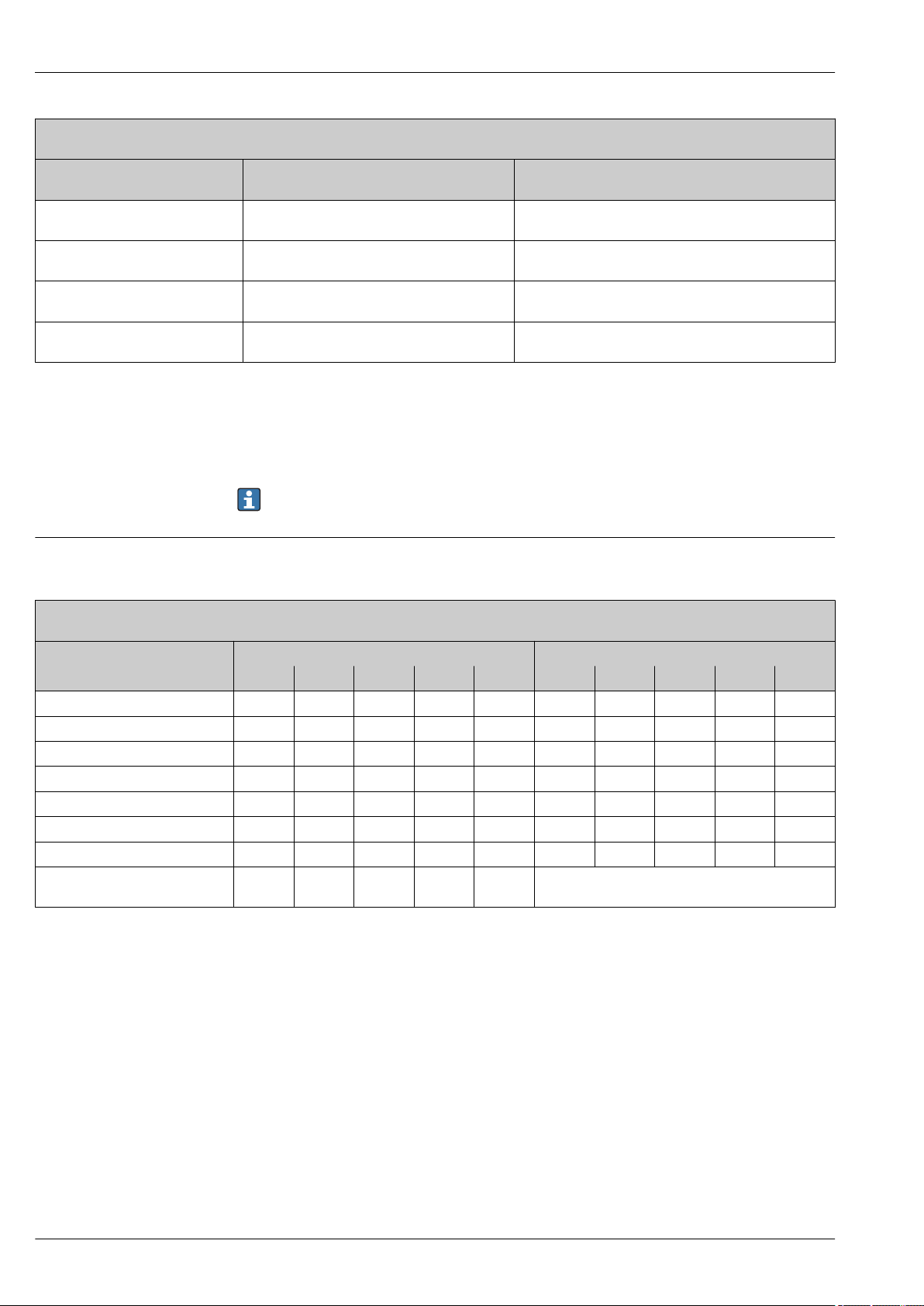
Total performance – Specification values
PMD75: total performance as %
The specifications refer to the calibrated span/Upper Range Value (URV).
Measuring cell Standard
TD 1:1 TD 2:1 TD 3:1 TD 4:1 TD 5:1 TD 1:1 TD 2:1 TD 3:1 TD 4:1 TD 5:1
10 mbar (0.15 psi) ±0.30 ±0.52 ±0.74 ±0.96 ±1.18 ±0.26 ±0.44 ±0.61 ±0.78 ±0.96
30 mbar (0.45 psi) ±0.26 ±0.41 ±0.56 ±0.72 ±0.88 ±0.24 ±0.38 ±0.52 ±0.67 ±0.81
100 mbar (1.5 psi) ±0.20 ±0.27 ±0.34 ±0.41 ±0.49 ±0.20 ±0.26 ±0.33 ±0.40 ±0.47
500 mbar (7.5 psi) ±0.11 ±0.14 ±0.17 ±0.20 ±0.23 ±0.10 ±0.13 ±0.16 ±0.19 ±0.22
3 bar (45 psi) ±0.14 ±0.18 ±0.23 ±0.28 ±0.33 ±0.11 ±0.13 ±0.16 ±0.18 ±0.20
16 bar (240 psi) ±0.12 ±0.16 ±0.20 ±0.25 ±0.30 ±0.10 ±0.12 ±0.14 ±0.16 ±0.18
40 bar (600 psi) ±0.12 ±0.16 ±0.20 ±0.25 ±0.30 ±0.10 ±0.12 ±0.14 ±0.16 ±0.18
160 bar (2 400 psi) rel/abs
250 bar (3 750 psi) rel/abs
1) The specification values apply to the temperature range per ±28 °C (50 °F) (corresponds to the range of –3 to +53 °C (+27 to +127 °F)) for all
measuring cells. The specifications apply to a static pressure of 7 bar (105 psi) for measuring cells of 10 mbar (0.15 psi) to 500 mbar (7.5 psi),
for larger measuring cells of 70 bar (1 050 psi). The specification values apply to the analog output (i.e. including electronics errors). The
specification values apply to membrane material AISI 316L (1.4435), Alloy C .
±0.17 ±0.20 ±0.24 ±0.28 ±0.32 -
1)
Platinum
1)
28 Endress+Hauser
Page 29

Deltabar S PMD75, FMD77, FMD78
Long-term stability
PMD75/FMD77/FMD78: long-term stability as %
The specifications refer to the upper range limit (URL)
Measuring cell Standard & platinum
10 mbar (0.15 psi) ± 0.200 ± 0.280 ± 0.310
30 mbar (0.45 psi) ± 0.200 ± 0.280 ± 0.310
100 mbar (1.5 psi) ± 0.080 ± 0.140 ± 0.270
500 mbar (7.5 psi) ± 0.025 ± 0.050 ± 0.075
3 bar (45 psi) ± 0.038 ± 0.075 ± 0.150
16 bar (240 psi) ± 0.025 ± 0.110 ± 0.210
40 bar (600 psi) ± 0.050 ± 0.070 ± 0.100
160 bar (2 400 psi) rel/abs
250 bar (3 750 psi) rel/abs
1) FMD77FMD78: No diaphragm seal errors are taken into account. Diaphragm seal errors can be calculated
separately in the Applicator diaphragm seal calculation module. Link to online tool Applicator:
www.endress.com/applicator → Sizing Diaphragm Seal
1)
.
1 year 5 years 10 years
± 0.050 ± 0.070 ± 0.100
Endress+Hauser 29
Page 30

Deltabar S PMD75, FMD77, FMD78
Detailed Performance Explanation and Calculation
To calculate the total performance outside the temperature range of –3 to +53 °C (+27 to +127 °F) or
for a membrane material other than 1.4435/316L or Alloy C 276, please refer to the following
sections: "Ambient temperature effect", "Static pressure effect" and "Calculating the total
performance"
1)
.
Ambient temperature effect [E2]
• E2 = (E2M · CF1 · CF2) + E2E + E2
LT
• E2M = Main temperature error
• CF1 = Temperature range correction factor
• CF2 = Membrane material correction factor (thermal)
• E2E = Electronics error for analog output
• E2LT = low temperature error
E2M - Main temperature error
The output changes due to the effect of ambient temperature [IEC 61298-3] with respect to
reference temperature [DIN 16086]. The values specify the maximum error due to min./max.
ambient or process temperature conditions.
PMD75/FMD77/FMD78: main temperature error E2M as % per ±28 °C (50 °F) (corresponds to the range
of –3 to +53 °C (+27 to +127 °F))
The specifications refer to the calibrated span/Upper Range Value (URV).
Measuring cell Standard Platinum
10 mbar (0.15 psi),
30 mbar (0.45 psi)
100 mbar (1.5 psi) ± (0.07 · TD + 0.07) ± (0.07 · TD + 0.07)
500 mbar (7.5 psi) ± (0.03 · TD + 0.017) ± (0.03 · TD + 0.017)
3 bar (45 psi),
16 bar (240 psi),
40 bar (600 psi)
160 bar (2 400 psi) rel/abs ± (0.042 · TD + 0.04) -
250 bar (3 750 psi) rel/abs ± (0.022 · TD + 0.04) -
± (0.14 · TD + 0.04) ± (0.14 · TD + 0.04)
± (0.012 · TD + 0.017) ± (0.012 · TD + 0.017)
CF1 - Temperature range correction factor
PMD75/FMD77/FMD78: correction factor CF
Measuring cell Temperature range Factor, CF
For all measuring cells 25 °C ± 28 °C (–3 to +53 °C (+27 to +127 °F)) 1
–32 to –4 °C (–26 to +25 °F) and
+54 to +85 °C (+129 to +185 °F)
–50 to –33 °C (–58 to –27 °F) 2.3
1
2
CF2 - Membrane material correction factor (thermal) (only for PMD75)
PMD75: correction factor CF
Measuring cell AISI 316L Alloy C Gold-Rhodium Monel Tantalum
10 mbar (0.15 psi) 1.0 1.0 2.5 2.8 2.3
30 mbar (0.45 psi) 1.0 1.0 2.5 2.8 2.3
100 mbar (1.5 psi) 1.0 1.0 1.1 1.1 1.1
500 mbar (7.5 psi) 1.0 1.0 1.8 1.8 1.8
1) FMD77FMD78: No diaphragm seal errors are taken into account. Diaphragm seal errors can be calculated separately in the Applicator
diaphragm seal calculation module. Link to online tool Applicator: www.endress.com/applicator → Sizing Diaphragm Seal
2
1
30 Endress+Hauser
Page 31

Deltabar S PMD75, FMD77, FMD78
PMD75: correction factor CF
Measuring cell AISI 316L Alloy C Gold-Rhodium Monel Tantalum
3 bar (45 psi) 1.0 1.0 3.1 3.1 3.1
16 bar (240 psi) 1.0 1.0 4.7 4.7 4.7
40 bar (600 psi) 1.0 1.0 3.1 3.1 3.1
160 bar (2 400 psi) rel/abs
250 bar (3 750 psi) rel/abs
2
1.0 1.0 - - -
E2E - Electronics error
PMD75/FMD77/FMD78: electronics error E2E as %
The specifications refer to the calibrated span/Upper Range Value (URV).
Measuring cell Electronics Temperature range Error
For all measuring cells Analog output (4 to 20 mA) –50 to +85 °C (–58 to +185 °F) 0.05
Digital output (HART) –50 to +85 °C (–58 to +185 °F) 0
Digital output (PA/FF) –40 to +85 °C (–40 to +185 °F) 0
1) The additional electronics error that occurs in the temperature range –50 to –41 °C (–58 to –42 °F) is
covered by E2LT.
1)
E2LT - low temperature error
PMD75/FMD77/FMD78: low temperature error E2LT as %
The specifications refer to the calibrated span/Upper Range Value (URV).
Measuring cell Temperature range Problem
For all measuring cells –40 to +85 °C (–40 to +185 °F) 0
–50 to –41 °C (–58 to –42 °F) 1.5
Static pressure effect [E3]
• E3 = E3M · CF
3
• E3M = main static pressure error (E3M = zero point error + span error)
• CF3 = Membrane material correction factor (static pressure)
E3M - Main static pressure error
Static pressure effect refers to the effect on the output due to changes in process static pressure.
It is the difference between the output at each static pressure and the output at atmospheric
pressure [IEC 61298-3]. It is the combination of influence of the operating pressure on the zero
point and span.
PMD75/FMD77/FMD78: main static pressure error E3M as %
The specifications refer to the calibrated span/Upper Range Value (URV).
Measuring cell Standard Platinum
on the zero point
10 mbar (0.15 psi) ± 0.15 · TD
per 7 bar (105 psi)
30 mbar (0.45 psi) ± 0.70 · TD
per 70 bar (1 050 psi)
100 mbar (1.5 psi) ± 0.203 · TD
per 70 bar (1 050 psi)
500 mbar (7.5 psi) ± 0.07 · TD
per 70 bar (1 050 psi)
1)
on the span on the zero point
± 0.035
per 7 bar (105 psi)
± 0.14
per 70 bar (1 050 psi)
± 0.15
per 70 bar (1 050 psi)
± 0.10
per 70 bar (1 050 psi)
± 0.07 · TD
per 7 bar (105 psi)
± 0.25 · TD
per 70 bar (1 050 psi)
± 0.077 · TD
per 70 bar (1 050 psi)
± 0.028 · TD
per 70 bar (1 050 psi)
1)
on the span
± 0.035
per 7 bar (105 psi)
± 0.14
per 70 bar (1 050 psi)
± 0.15
per 70 bar (1 050 psi)
± 0.10
per 70 bar (1 050 psi)
Endress+Hauser 31
Page 32

Deltabar S PMD75, FMD77, FMD78
PMD75/FMD77/FMD78: main static pressure error E3M as %
The specifications refer to the calibrated span/Upper Range Value (URV).
Measuring cell Standard Platinum
on the zero point
3 bar (45 psi) ± 0.049 · TD
per 70 bar (1 050 psi)
16 bar (240 psi),
40 bar (600 psi)
160 bar (2 400 psi) rel/abs
± 0.049 · TD
per 70 bar (1 050 psi)
- - - -
1)
on the span on the zero point
± 0.05
per 70 bar (1 050 psi)
± 0.02
per 70 bar (1 050 psi)
± 0.021 · TD
per 70 bar (1 050 psi)
± 0.021 · TD
per 70 bar (1 050 psi)
250 bar (3 750 psi) rel/abs
1) The influence of the operating pressure on the zero point can be corrected. Please refer to operating instructions and chapter Commissioning →
Position adjustment.
CF3 – Membrane material correction factor (static pressure) (applicable only to PMD75)
1)
on the span
± 0.05
per 70 bar (1 050 psi)
± 0.02
per 70 bar (1 050 psi)
PMD75: membrane material correction factor CF3
3
Measuring cell AISI 316L Alloy C Gold-Rhodium Monel Tantalum
10 mbar (0.15 psi) 1.0 1.0 1.0 1.4 2.1
30 mbar (0.45 psi) 1.0 1.0 1.5 2.0 3.1
100 mbar (1.5 psi) 1.0 1.0 2.5 2.5 2.5
500 mbar (7.5 psi) 1.0 1.0 1.2 1.2 1.8
3 bar (45 psi) 1.0 1.0 2.1 2.1 2.8
16 bar (240 psi) 1.0 1.0 3.0 3.0 4.0
40 bar (600 psi) 1.0 1.0 3.0 3.0 4.0
160 bar (2 400 psi) rel/abs
- - - - -
250 bar (3 750 psi) rel/abs
Total error
Total error = total performance + long-term stability
Total performance as % of the set span with TD 1:1 → 28
Long-term stability as % of the upper range limit (URL) → 29
PMD75: total error as %
The specifications refer to the upper range limit (URL).
Measuring cell Standard
1)
Platinum
1 year 5 years 10 years 1 year 5 years 10 years
10 mbar (0.15 psi) ± 0.50 ± 0.58 ± 0.61 ± 0.46 ± 0.54 ± 0.57
30 mbar (0.45 psi) ± 0.46 ± 0.54 ± 0.57 ± 0.44 ± 0.52 ± 0,55
100 mbar (1.5 psi) ± 0.28 ± 0.34 ± 0,47 ± 0.28 ± 0.34 ± 0,47
500 mbar (7.5 psi) ± 0.14 ± 0.16 ± 0.19 ± 0,13 ± 0.15 ± 0.18
3 bar (45 psi) ± 0.17 ± 0.21 ± 0.29 ± 0.15 ± 0.19 ± 0.26
16 bar (240 psi) ± 0.14 ± 0.23 ± 0.33 ± 0.12 ± 0.21 ± 0.31
40 bar (600 psi) ± 0.17 ± 0.19 ± 0.22 ± 0.15 ± 0.17 ± 0.20
160 bar (2 400 psi) rel/abs
± 0.22 ± 0.24 ± 0,27 -
250 bar (3 750 psi) rel/abs
1)
1) The specification values apply to the temperature range per ±28 °C (50 °F) (corresponds to the range of –3 to +53 °C (+27 to +127 °F)) for all
measuring cells. The specifications apply to a static pressure of 7 bar (105 psi) for measuring cells of 10 mbar (0.15 psi) to 500 mbar (7.5 psi),
for larger measuring cells of 70 bar (1 050 psi). The specification values apply to the analog output (i.e. including electronics errors). The
specification values apply to membrane material AISI 316L (1.4435), Alloy C .
32 Endress+Hauser
Page 33

Deltabar S PMD75, FMD77, FMD78
Performance characteristics - calculation example and additional information
Calculating the total performance in 5 steps
Data (Example)
Measuring Conditions / Device configuration
dP range (URV) 8 bar (116 psi)
Min./ Max. temp. differential pressure transmitter
(ambient/process)
Membrane material AISI 316L
Reference accuracy (± 0.05%) Standard
PMD75 - suitable measuring cell
(upper range limit, URL)
Static pressure 35 bar (508 psi)
Output Signal 4 to 20 mA
Ambient temp.:0 to 45 °C (32 to 113 °F)
Max. Process temp.:50 °C (122 °F)
16 bar (240 psi) with TD 2:1
Formula
Total performance = ± √ ( (E1)² + (E2)² + (E3)² )
E1 = Reference accuracy → 27
E2 = Ambient temperature effect per ±28 °C (50 °F) (corresponds to the range of
–3 to +53 °C (+27 to +127 °F)) → 30
E3 = Static pressure effect → 31
Calculation
Step 1: Calculating the turn down → 7
Turn down (TD) = URL/|URV - LRV| = 16 bar (240 psi)/8 bar (116 psi)
= TD = 2:1
Step 2: Calculating the reference accuracy (E1) → 27
For the measuring conditions,
Reference accuracy, E1 = ± 0.05 (% of the set span)
= ± (0.05/100) · 8 bar (116 psi)
= ±0.0040 bar (0.0580 psi)
E1 = ± 0.05 (% of the set span)
(or) ±0.0040 bar (0.0580 psi)
Endress+Hauser 33
Page 34

Deltabar S PMD75, FMD77, FMD78
A
B
C
0.0
0.02
0.04
0.06
0.08
0.1
0.12
0.14
0.16
[%]
-40
-40
-30
-22
-10
+140+32
+10
+50
+20
+68
+30
+86
+40
+104
+50
+122
+60
+140
+70
+158
+80
+176
+90
+194
-20
-4
[°C]
[°F]
D
Step 3: Calculation of the ambient temperature effect [E2 = (E2M · CF1 · CF2) + E2E + E2LT] → 30
For the measuring conditions,
Main temperature error, E2
Temperature correction factor, CF
Membrane material correction factor, CF
Electronics error , E2
Low temperature error E2
Ambient temperature effect, E2 = ± [(0.012 · TD + 0.017) · 1 · 1] +0.05
M
1
2
E
LT
=
± (0.012 · TD + 0.017) % of the set span
= 1
= 1
= 0.05 %
= 0 %
= ± [(0.012 · 2 + 0.017) · 1 · 1] + 0.05
= ± 0.091 (% of the set span)
= ± (0.091/100) · 8 bar (116 psi)
= ±0.0073 bar (0.10585 psi)
E2 = ± 0.091 (% of the set span)
(or) ±0.0073 bar (0.10585 psi)
A Error (% of the set span)
B Temperature
C Measuring membrane made from 316L or Alloy C
D Ambient temperature effect: 0.091 (% of the set span) (E2 at 50 °C (122 °F))
34 Endress+Hauser
A0031069
Page 35

Deltabar S PMD75, FMD77, FMD78
A
B
0.00
0.20
0.40
0.60
0.80
[%]
3
45
4
60
6907
1058120913510150111651218013195142101522516240
5
75
[bar]
[psi]
TD 2:1
TD 5:1
TD 4:1
TD 3:1
TD 1:1
C
Step 4: Calculating the static pressure effect (E3 = E3M · CF3) → 31
For the measuring conditions,
Main static pressure error, E3
Error factor dependent on membrane material, CF
Static pressure effect, E3 = ± (0.049 · TD + 0.02) · (35/70) · CF3 (% of the set span)
Step 5: Calculation of total performance
Total performance = ± √ ((E1)² + (E2)² + (E3)² )
Total performance, in mbar = ± √ ((0.004)² + (0.0073)² + (0.0047)² )
Total performance, in % of the set span = ± √ ((0.05)2 + (0.091)2 + (0.059)2)
Total performance = ± 0.119 (% of the set span)
M
3
= ± 0.0095 bar (0.13775 psi) or 9.5 mbar (0.13775 psi)
~ 0.119 % of 8 bar (116 psi)
(or)
= ± 0.119 (% of the set span)
(or) ±0.0095 bar (0.13775 psi)
=± (0.049 · TD) on the zero point and
± 0.02 on the span (% of the set span)
per 70 bar (1 015 psi)
= [± (0.049 · TD) on the zero point and
± 0.02 on the span] · (35/70) (% of the set span)
per 35 bar (507.50 psi)
= 1
= ± (0.049 · 2 + 0.02) · (0.5) · 1
= ± 0.059 (% of the set span)
= ± (0.059/100) · 8 bar (116 psi)
= ±0.0047 bar (0.06815 psi)
E3 = ± 0.059 (% of the set span)
(or) ±0.0047 bar (0.06815 psi)
E1 = Reference accuracy
E2 = Ambient temperature effect per ±28 °C (50 °F) (corresponds to the range of
–3 to +53 °C (+27 to +127 °F))
E3 = Static Pressure Effect
A Error (% of the set span)
B Set span [bar]
C Standard measuring cell
A0031070
Endress+Hauser 35
Page 36

Deltabar S PMD75, FMD77, FMD78
C
B
C
A
A
PMD75 FMD77
B
90°
90°
90°
90°
+
-
+
-
+
-
+
-
+
-
Installation factors
Some of the influencing factors are:
• Influence of installation position → 36
• Vibration effects → 36
Influence of installation position
A0031035
Device Calibration position (A) Device rotated vertically downwards (B) Device rotated vertically upwards (C)
PMD75 and silicone oil No additional error <+4 mbar (+0.06 psi)
The value is doubled for inert oil.
FMD77 and silicone oil No additional error <+32 mbar (+0.46 psi)
The value is doubled for inert oil.
<–4 mbar (–0.06 psi)
The value is doubled for inert oil.
<–32 mbar (–0.46 psi)
The value is doubled for inert oil.
A position-dependent zero point shift can be corrected. Please refer to operating instructions
chapter Commissioning → Position adjustment.
Vibration effects
Device/accessory Measuring cells Housing Test standard Vibration resistance
10 mbar (0.15 psi),
30 mbar (0.45 psi)
T14 stainless steel
T15 aluminum
IEC 61298-3
T17 aluminum
T14 aluminum IEC 61298-3
≤ 0.15% URL to 10 to 38 Hz:
±0.35 mm (0.0138 in);
38 to 2000 Hz: 2 g in all 3 planes
≤ 0.15% URL to 10 to 60 Hz:
±0.21 mm (0.0083 in);
60 to 2000 Hz: 3 g in all 3 planes
PMD75
T14 stainless steel
T15 aluminum
≥100 mbar (1.5 psi)
T14 aluminum IEC 61298-3
IEC 61298-3
≤ 0.075 % URL to 10 to 38 Hz:
±0.35 mm (0.0138 in);
38 to 2000 Hz: 2 g in all 3 planes
≤ 0.075 % URL to 10 to 60 Hz:
±0.35 mm (0.0138 in);
60 to 2000 Hz: 5 g in all 3 planes
Performance Characteristics Conformance
All performance characteristics are in conformance to ≥ ± 3 sigma.
Resolution
Current output: 1 μA
36 Endress+Hauser
Page 37

Deltabar S PMD75, FMD77, FMD78
Warm-up period
• 4 to 20 mA HART: < 10 s
• PROFIBUS PA: 6 s
• FOUNDATION Fieldbus: 50 s
Reference operating conditions
• As per IEC 60770
• Ambient temperature TA = constant, in the range +21 to +33 °C (+70 to +91 °F)
•
Humidity j = constant, in the range: 5 to 80 % RH ± 5 %
• Ambient pressure pA = constant, in range: 860 to 1 060 mbar (12.47 to 15.37 psi)
• Position of measuring cell: horizontal ±1° (see also "Influence of installation position"
section→ 36)
• Input of LOW SENSOR TRIM and HIGH SENSOR TRIM for lower range value and upper range value
• Zero based span
• Membrane material for PMD75: AISI 316L (1.4435), Alloy C276, gold/rhodium-coated, Monel
• Membrane material for FMD77, FMD78: AISI 316L (1.4435)
• Filling oil: silicone oil
• Supply voltage: 24 V DC ±3 V DC
• Load with HART: 250 Ω
• Turn down (TD) = URL/|URV - LRV|
Endress+Hauser 37
Page 38

Installation
Deltabar S PMD75, FMD77, FMD78
General installation instructions
Measuring arrangement Flow measurement
• A position-dependent zero point shift can be corrected directly at the device via operating keys,
and also in hazardous areas in the case of devices with external operation.
Diaphragm seals also shift the zero point, depending on the installation position → 98.
• The device housing can be rotated up to 380° .
• Endress+Hauser offers a mounting bracket for installing the device on pipes or walls → 39.
• Use flushing rings for flange and cell diaphragm seals if buildup or clogging can be expected at the
diaphragm seal connection. The flushing ring can be fitted between the process connection and
diaphragm seal. Material buildup in front of the process isolating diaphragm can be flushed away,
and the pressure chamber vented, via the two lateral flushing holes.
• When measuring in media containing solids, such as dirty liquids, installing separators and drain
valves is useful for capturing and removing sediment.
• Using a valve manifold allows for easy commissioning, installation and maintenance without
interrupting the process.
• General recommendations for the pressure piping can be found in DIN 19210 "Methods for
measurement of fluid flow; differential piping for flow measurement devices" or the corresponding
national or international standards.
• Install the pressure piping with a continuous gradient of at least 10%.
• When routing the pressure piping outdoors, ensure sufficient anti-freeze protection, e.g. by using
pipe heat tracing.
• Point the cable and connector downwards where possible to prevent moisture from entering (e.g.
rain or condensation water).
• The PMD75 is best suited to flow measurement.
• Measuring arrangement for gases: Mount device above the measuring point.
• Measuring arrangement for liquids and vapors: Mount device below the measuring point.
• For flow measurement in vapors, mount the condensate traps at the same level as the tapping
point and at the same distance from the Deltabar S.
Measuring arrangement for devices with diaphragm seals – FMD77 and FMD78
Level measurement
The PMD75 and FMD77 are best suited to level measurement in open containers. All Deltabar S
devices are suitable for level measurement in closed vessels.
Measuring arrangement for level measurement in open containers
• PMD75: Mount device below the lower measuring connection. The negative side is open to
atmospheric pressure.
• FMD77: Mount device directly on the vessel. The negative side is open to atmospheric pressure.
Measuring arrangement for level measurement in closed containers and closed containers with
superimposed vapor
• PMD75: Mount device below the lower measuring connection. Always connect the negative side
above the maximum level via pressure piping.
• FMD77: Mount device directly on the vessel. Always connect the negative side above the
maximum level via pressure piping.
• In the case of level measurement in closed vessels with superimposed vapor, a condensate trap
ensures the pressure remains constant on the minus side.
Pressure measurement
• The PMD75 and FMD78 are best suited to differential pressure measurement.
• Measuring arrangement for gases: Mount device above the measuring point.
• Measuring arrangement for liquids and vapors: Mount device below the measuring point.
• For differential pressure measurement in vapors, mount the condensate traps at the same level as
the tapping point and at the same distance from the Deltabar S.
→ 94
Orientation
The orientation may cause a zero point shift, see → 36.
This position-dependent zero point shift can be corrected directly at the device via the operating key,
and also in hazardous areas in the case of devices with external operation (position adjustment).
38 Endress+Hauser
Page 39

Deltabar S PMD75, FMD77, FMD78
Wall and pipe mounting, transmitter (optional)
Endress+Hauser offers the following mounting bracket for installing the device on pipes or walls:
Standard version Heavy-duty version
A0031326 A0031327
• The standard mounting bracket version is not suitable for use in an application subject to
vibrations.
• The vibration resistance of the heavy-duty mounting bracket has been tested according to IEC
61298-3, see the "Vibration resistance" section → 44.
• If a valve manifold is used, its dimensions should also be taken into consideration.
• Bracket for wall and pipe mounting including retaining bracket for pipe mounting and two nuts.
• The material of the screws used to secure the device depend on the order code.
• For the technical data (such as the dimensions or order numbers for screws), see the document
SD01553P/00/EN.
Ordering information:
• Standard version: Product Configurator, order code for "Additional options" option "Q" or
• Standard version: Product Configurator, order code for "Accessories enclosed" option "PD"
• Heavy-duty version: Product Configurator, order code for "Additional options" option "U" or
• Heavy-duty version: Product Configurator, order code for "Accessories enclosed" option "PB"
Wall and pipe mounting, valve manifold (optional)
A0032335
For the technical data (such as the dimensions or order numbers for screws), see the document
SD01553P/00/EN.
Ordering information:
Product Configurator, order code for "Accessories enclosed", option "PJ"
Endress+Hauser 39
Page 40

Deltabar S PMD75, FMD77, FMD78
r ³ 120 (4.72)
2 31
4
5
"Separate housing" version
With the "separate housing" version, you are able to mount the housing with the electronics insert at
a distance from the measuring point. This version facilitates trouble-free measurement
• Under particularly difficult measuring conditions (at installation locations that are cramped or
difficult to access)
• If rapid cleaning of the measuring point is required and
• If the measuring point is exposed to vibrations.
You can choose between different cable versions:
• PE: 2 m (6.6 ft), 5 m (16 ft) and 10 m (33 ft)
• FEP: 5 m (16 ft).
Ordering information: Product Configurator, order code for "Additional options 2", version "G".
Dimensions → 78
In the case of the "separate housing" version, the sensor is delivered with the process connection and
cable ready mounted. The housing and a mounting bracket are enclosed as separate units. The cable
is provided with a socket at both ends. These sockets are simply connected to the housing and the
sensor.
1 Process connection with sensor - For degrees of protection, see the following section
2 Process connection adapter (weight: 0.93 kg (2.05 lb))
3 Cable (weight: 0.05 kg/meter (0.11 lb)), both ends are fitted with a socket
4 Mounting bracket provided, suitable for pipe and wall mounting
5 Housing with electronic insert - degrees of protection → 49
Engineering unit mm (in)
Degree of protection for the process connection and sensor with the use of
• FEP cable:
– IP 69
2)
– IP 66 NEMA 4/6P
– IP 68 (1.83 mH2O for 24 h) NEMA 4/6P
• PE cable:
– IP 66 NEMA 4/6P
– IP 68 (1.83 mH2O for 24 h) NEMA 4/6P
Technical data of the PE and FEP cable:
• Minimum bending radius: 120 mm (4.72 in)
• Cable extraction force: max. 450 N (101.16 lbf)
• Resistance to UV light
Use in hazardous area:
• Intrinsically safe installations (Ex ia/IS)
• FM/CSA IS: for Div. 1 installation only
A0023925
2) Designation of the IP protection class according to DIN EN 60529. Previous designation "IP69K" according to DIN 40050 Part 9 is no longer valid
(standard withdrawn on November 1, 2012). The tests required by both standards are identical.
40 Endress+Hauser
Page 41

Deltabar S PMD75, FMD77, FMD78
81 (3.19)
62 (2.44)
T14
T17
11
ø54.1 (2.13)
45 (1.77)
r ³120 (4.72) r ³ 120 (4.72)
+
–
+
–
+
–
+
–
T14
T15
T17
2 3
Reduction of the installation height
If the separate housing is used, the installation height of the process connection is reduced compared
to the dimensions of the standard version.
1 Process connection adapter
Engineering unit mm (in)
A0023926
Turning the housing
The housing can be rotated up to 380° by loosening the Allen screw.
Your benefits
• Easy mounting due to optimum alignment of housing
• Good, accessible device operation
• Optimum readability of the onsite display (optional).
A0019996
Endress+Hauser 41
Page 42

Deltabar S PMD75, FMD77, FMD78
Oxygen applications
Order code for devices
cleaned for oxygen applications
PMD75 – * * * ** * * * K * * or
PMD75 – * * * ** * * * H * * HB
PMD75 – * * * ** * * * 2 * * or
PMD75 – * * * ** * * * A * * HB
PMD75 – * * * ** * * * 3 * * or
PMD75 – * * * ** * * * C * * HB
FMD77 – * * * ** T * F * * or
FMD77 – * * * ** D * F * * HB
FMD78 – * * * ** * ** 4 * * or
FMD78 – * * * ** * ** 6 * * HB
FMD78 – * * * ** * ** D * * or
FMD78 – * * * ** * ** F * * HB
1)
,
Oxygen and other gases can react explosively to oils, grease and plastics, such that, among other
things, the following precautions must be taken:
• All components of the system, such as measuring devices, must be cleaned in accordance with the
BAM (DIN 19247) requirements.
• Dependent on the materials used, a certain maximum temperature and a maximum pressure for
oxygen applications must not be exceeded.
The devices suitable for gaseous oxygen applications are listed in the following table with the
specification p
max
.
HB = Cleaned for oxygen service
p
for oxygen applications T
max
160 bar (2 400 psi) 85 °C (185 °F)
160 bar (2 400 psi) 60 °C (140 °F)
160 bar (2 400 psi) 60 °C (140 °F)
PN of the flange 60 °C (140 °F)
Depends on filling oil:
max. 160 bar (2 400 psi)
for oxygen applications
max
85 °C (185 °F)
1) Devices only, not accessories or enclosed accessories.
Ultrapure gas applications
Endress+Hauser also offers devices for special applications, such as ultrapure gas, cleaned from oil
and grease. No special restrictions regarding the process conditions apply to these devices.
Ordering information:
• PMD75: Product Configurator, order code for "Seal"
• FMD77: Product Configurator, order code for "Process connection low-pressure side; Material;
Seal".
Applications with hydrogen
A gold-plated metal process isolating diaphragm offers universal protection against hydrogen
diffusion, both in gas applications and in applications with aqueous solutions.
Applications with hydrogen in aqueous solutions
A gold/rhodium-plated metal process isolating diaphragm (AU/Rh) offers effective protection
against hydrogen diffusion.
42 Endress+Hauser
Page 43

Deltabar S PMD75, FMD77, FMD78
Environment
Ambient temperature range
Storage temperature range
Version PMD75 FMD77 FMD78
Without LCD display –50 to +85 °C (–58 to +185 °F)
With LCD display
With separate housing - –20 to +60 °C (–4 to +140 °F)
Diaphragm seal systems
1) If the temperature is below –40 °C (–40 °F), chances of failure increases. Product Configurator, order code
for "Test, certificate" option "JN".
2) Extended temperature application range (–50 to +85 °C (–58 to +185 °F)) with restrictions in optical
properties, such as display speed and contrast
3) Ambient temperature range and process temperature range are mutually dependent - see "Heat insulation"
section
2)
3)
–20 to +70 °C (–4 to +158 °F)
- → 94
1)
Hazardous areas
• For devices for use in hazardous areas, see Safety Instructions, Installation or Control
Drawing→ 113.
• Pressure measuring devices that have the usual explosion protection certificates (e.g. ATEX-/
CSA-/ FM-/ IEC Ex,...) can be used in hazardous areas at ambient temperatures down to
–50 °C (–58 °F). The functionality of the explosion protection is also guaranteed for ambient
temperatures down to –50 °C (–58 °F).
• –40 to +90 °C (–40 to +194 °F)
• Local display: –40 to +85 °C (–40 to +185 °F)
• Separate housing:–40 to +60 °C (–40 to +140 °F)
• Devices with PVC-sheathed capillary: –25 to +90 °C (–13 to +194 °F)
Degree of protection
Climate class
Electromagnetic compatibility
Depends on the deployed
• Housing → 49
• Separate housing → 40
Class 4K4H (air temperature: –20 to +55 °C (–4 to +131 °F), relative humidity: 4 to 100 %) fulfilled
as per DIN EN 60721-3-4 (condensation possible.)
• Electromagnetic compatibility as per EN 61326 and NAMUR recommendation EMC (NE21).
• With enhanced immunity against electromagnetic fields as per EN 61000-4-3: 30 V/m with
closed cover (for devices with T14 housing or T15 housing)
• Maximum deviation: < 0.5 % of span
• All EMC measurements were performed with a turn down (TD) = 2:1.
For further details refer to the Declaration of Conformity.
Endress+Hauser 43
Page 44

Deltabar S PMD75, FMD77, FMD78
Vibration resistance
Device/accessory Measuring cells Housing Test standard Vibration resistance
PMD75
With mounting bracket
(heavy duty design)
FMD77 All All IEC 61298-3:1998
T14 stainless steel
T15 aluminum
10 mbar (0.15 psi),
30 mbar (0.45 psi)
≥100 mbar (1.5 psi)
All All IEC 61298-3
T17 aluminum
T14 aluminum IEC 61298-3
T14 stainless steel
T15 aluminum
T14 aluminum IEC 61298-3
IEC 61298-3
IEC 61298-3
Guaranteed for 10 to 38 Hz:
±0.35 mm (0.0138 in);
38 to 2000 Hz: 2 g in all 3 planes
Guaranteed for 10 to 60 Hz:
±0.21 mm (0.0083 in);
60 to 2000 Hz: 3 g in all 3 planes
Guaranteed for 10 to 38 Hz:
±0.35 mm (0.0138 in);
38 to 2000 Hz: 2 g in all 3 planes
Guaranteed for 10 to 60 Hz:
±0.35 mm (0.0138 in);
60 to 2000 Hz: 5 g in all 3 planes
Guaranteed for 10 to 60 Hz:
±0.15 mm (0.0059 in);
60 to 500 Hz: 2 g in all 3 planes
Guaranteed for 10 to 60 Hz:
±0.075 mm (0.0030 in);
60 to 150 Hz: 1 g in all 3 planes
44 Endress+Hauser
Page 45

Deltabar S PMD75, FMD77, FMD78
Process
Process temperature limits (temperature at transmitter)
PMD75
• Process connections made of 316L or Alloy C276: –50 to +85 °C (–58 to +185 °F)
3)
• Process connections made of C22.8: –10 to +85 °C (+14 to +185 °F)
• For oxygen applications, note → 42"Oxygen applications" section.
• Pay attention to the process temperature range of the seal. See also the following section "Process
temperature range, seals".
FMD77
• Depends on the design (see the following table)
• Dependent on diaphragm seal and filling oil (→ 97): –70 to +400 °C (–94 to +752 °F)
• For oxygen applications, note → 42"Oxygen applications" section.
• Pay attention to the process temperature range of the seal. See also the following section "Process
temperature range, seals".
• Please observe the temperature application limits of the diaphragm seal oil. → 97,
"Diaphragm seal filling oils" section.
• Please observe the maximum gauge pressure and maximum temperature.
Design Temperature isolator Temperature Option
Transmitter horizontal long 400 °C (752 °F) MA
Transmitter vertical long 300 °C (572 °F) MB
Transmitter horizontal short 200 °C (392 °F) MC
Transmitter vertical short 200 °C (392 °F) MD
U-bracket, Transmitter horizontal
(for devices which require a CRN approval)
- 400 °C (752 °F)
1)
2)
1) Product Configurator, "Process connection" ordering feature
2) In combination with CSA approval.
FMD78
• Dependent on diaphragm seal and filling oil:–70 to +400 °C (–94 to +752 °F)
• For oxygen applications, note → 42"Oxygen applications" section.
• Please observe the temperature application limits of the diaphragm seal oil. → 97,
"Diaphragm seal filling oils" section.
• Please observe the maximum gauge pressure and maximum temperature.
FMD77 and FMD78: Devices with PTFE-coated process isolating diaphragm
The non-stick coating has excellent gliding properties and is used to protect the process isolating
diaphragm against abrasive media.
NOTICE
Incorrect use of the PTFE foil will destroy the device!
The PTFE foil is designed to protect the unit against abrasion. It does not provide protection
‣
against corrosive media.
For the range of application of the 0.25 mm (0.01 in) PTFE foil on an AISI 316L (1.4404/1.4435)
process isolating diaphragm, see the following diagram:
3) If the temperature is below –40 °C (–40 °F), increased failure rates are likely. Product Configurator, order code for "Test, certificate" option "JN".
Endress+Hauser 45
Page 46

Deltabar S PMD75, FMD77, FMD78
[°F]
g
0
725
1450
2175
2900
3625
-40 77 122 167 212 257
302
347
392
T
p
T
a
+32
+80
40
+185
113
200
100
−70
300
392
392
+32
−94
572
[°C]
[°F]
[°C][°F]
− −40 25
− −40 22
0
0
T
a
T
p
A0026949-EN
Process temperature limits of capillary armoring: FMD77 and FMD78
For vacuum applications: p
+150 °C (302 °F).
• 316L: No restrictions
• PTFE: No restrictions
• PVC: See the following diagram
≤ 1 bar (14.5 psi)to 0.05 bar (0.725 psi)up to max.
abs
A0028096
Process temperature range,
PMD75
seals
1)
Seal Process temperature range
FKM Viton –20 to +85 °C (–4 to +185 °F) A
PTFE –50 to +85 °C (–58 to +185 °F) C
NBR –20 to +85 °C (–4 to +185 °F) F
Copper –40 to +85 °C (–40 to +185 °F) H
Copper, cleaned for oxygen service –20 to +85 °C (–4 to +185 °F) K or H
FKM Viton, cleaned from oil and grease –10 to +85 °C (+14 to +185 °F) 1
FKM Viton, cleaned for oxygen service –10 to +60 °C (+14 to +140 °F) 2 or A
PTFE, cleaned for oxygen applications –20 to +60 °C (–4 to +140 °F) 3 or C
4)
EPDM
1) lower temperatures on request
2) Product Configurator, "Seal" ordering feature
3) with option "HB", see Product Configurator, order code for "Service"
4) Always for LP side with blind flange (see Product Configurator, order code for "Process connection").
–40 to +85 °C (–40 to +185 °F) J
46 Endress+Hauser
Option
2)
3)
3)
3)
Page 47

Deltabar S PMD75, FMD77, FMD78
FMD77 (with diaphragm seal)
Seal on the LP side (–) Process temperature range
FKM Viton –20 to +85 °C (–4 to +185 °F) See the "Measuring range" section
PTFE –50 to +85 °C (–58 to +185 °F) H, J
EPDM –40 to +85 °C (–40 to +185 °F) K, L
FKM Viton, cleaned from
oil and grease
FKM Viton, cleaned for
oxygen service
Kalrez, Compound 6375 0 to +5 °C (+32 to +41 °F) 44...49 (660...735) 29...33 (435...495) M, N
Chemraz, Compound 505 –10 to +25 °C (+14 to +77 °F) 130...160 (1950...2400) 87...107 (1305...1605) P, Q
Diaphragm seal and
capillary, welded
1) lower temperatures on request
2) Product Configurator, order code for "Process connection, LP side; seal:"
3) with option "HB", see Product Configurator, order code for "Service"
Pressure specifications
–10 to +85 °C (+14 to +185 °F) S
–10 to +60 °C (+14 to +140 °F) T or D
+5 to +10 °C (+41 to +50 °F) 49...160 (735...2400) 33...107 (495...1605)
+10 to +85 °C (+50 to +185 °F) 160 (2400) 107 (1605)
+25 to +85 °C (+77 to +185 °F) 160 (2400) 107 (1605)
Please observe the temperature application limits of the diaphragm seal oil. → 97, "Diaphragm seal filling oils" section.
WARNING
L
1)
OPL bar (psi) PN bar (psi) Option
"FMD77, FMD78, PMD75: Option PN 160 / 16 MPa / 2400 psi"
→ 12.
B, D, F, U
The maximum pressure for the measuring device depends on the lowest-rated element with
regard to pressure.
For pressure specifications, see the "Measuring range" section and the "Mechanical construction"
‣
section.
The measuring device must be operated only within the specified limits!
‣
MWP (maximum working pressure): The MWP (maximum working pressure) is specified on the
‣
nameplate. This value refers to a reference temperature of +20 °C (+68°F) and may be applied to
the device for an unlimited time. Observe temperature dependency of the MWP. The pressure
values permitted at higher temperatures can be found in the standards EN 1092-1: 2001 Tab. 18
(With regard to their stability-temperature property, the materials 1.4435 and 1.4404 are
grouped together under 13EO in EN 1092-1 Tab. 18. The chemical composition of the two
materials can be identical.), ASME B 16.5a – 1998 Tab. 2-2.2 F316, ASME B 16.5a – 1998 Tab.
2.3.8 N10276, JIS B 2220.
The test pressure corresponds to the over pressure limit of the individual sensors (OPL = 1.5 x
‣
MWP ) and may be applied only for a limited period of time to prevent any lasting damage.
The Pressure Equipment Directive (2014/68/EU) uses the abbreviation "PS". The abbreviation "PS"
‣
corresponds to the MWP (maximum working pressure) of the measuring device.
In the case of sensor range and process connections where the over pressure limit (OPL) of the
‣
process connection is smaller than the nominal value of the sensor, the device is set at the
factory, at the very maximum, to the OPL value of the process connection. If you want to use the
entire sensor range, select a process connection with a higher OPL value (1.5 x PN; MWP = PN)
In oxygen applications, the values for "p
‣
max
and T
for oxygen applications must not be
max
exceeded→ 42.
For the PMD75, the MWP applies to the temperature ranges specified in the "Ambient
‣
temperature range" → 43 and "Process temperature limits" → 45 sections.
2)
3)
Endress+Hauser 47
Page 48

Mechanical construction
B
A
C
C
C
A
A
b
b
D
D
B
B
A
b
b
C
Deltabar S PMD75, FMD77, FMD78
Device height
The device height is calculated from
• the height of the housing
• the height of optional mounted parts such as temperature isolators or capillaries
• the height of the relevant process connection.
The individual heights of the components can be found in the following sections. To calculate the
device height, simply add up the individual heights of the components. If necessary, the installation
space (the space used to install the device) must also be taken into account. You can use the
following table for this:
PMD75
Designation Position Dimension Example
Side flanges (A) 85 mm (3.35 in)
Height of housing (B) → 49 ff.
Installation space (C) -
Device height
FMD77
A0023927
Designation Position Dimension Example
Mounted parts (A) → 57
Side flanges (B) 85 mm (3.35 in)
Height of housing (C) → 49 ff.
Installation space (D) -
Process connections (b) → 51
Device height
FMD78
Designation Position Dimension Example
Side flanges (A) 85 mm (3.35 in)
Height of housing (B) → 49 ff.
Installation space (C) -
A0025880
Process connections (b) → 51
Device height
48 Endress+Hauser
A0025881
Page 49

Deltabar S PMD75, FMD77, FMD78
152 (5.98)
111 (4.37) 111 (4.37)
129 (5.08)
T14 housing, optional display on the side
Engineering unit mm (in). Front view, left-hand side view, top view
A0019997
Material Degree of protection Cable entry Weight in kg (lb) Option
Housing Cover seal with display without display
IP66/67 NEMA 6P M20 gland
IP66/67 NEMA 6P G ½" thread B
IP66/67 NEMA 6P NPT ½" thread C
Aluminum EPDM
IP66/67 NEMA 6P M12 plug D
IP66/67 NEMA 6P 7/8" plug E
IP65 NEMA 4 HAN7D plug 90 degrees F
IP66/67 NEMA 6P M20 gland
IP66/67 NEMA 6P G ½" thread 2
IP66/67 NEMA 6P NPT ½" thread 3
EPDM
IP66/67 NEMA 6P M12 plug 4
316L
IP66/67 NEMA 6P 7/8" plug 5
IP65 NEMA 4 HAN7D plug 90 degrees 6
FVMQ IP66/67 NEMA 6P M20 gland 7
FVMQ IP66/67 NEMA 6P NPT ½" thread 8
1) Product Configurator, order code for "Housing, cover seal, cable entry, degree of protection"
1.2 (2.65) 1.1 (2.43)
2.1 (4.63) 2.0 (4.41)
A
1
1)
Endress+Hauser 49
Page 50

T15 housing, optional
127 (5)
155 (6.1)
138 (5.43)
150 (5.91)
115 (4.53)
94 (3.7)
132 (5.2)
115 (4.53)
147 (5.79)
display on the top
Deltabar S PMD75, FMD77, FMD78
A0019999
Engineering unit mm (in). Front view, left-hand side view, top view
Material Degree of protection Cable entry Weight in kg (lb) Option
Housing Cover seal with display without display
IP66/67 NEMA 6P M20 gland
IP66/67 NEMA 6P G ½" thread K
IP66/67 NEMA 6P NPT ½" thread L
Aluminum EPDM
IP66/67 NEMA 6P M12 plug M
IP66/67 NEMA 6P 7/8" plug N
IP65 NEMA 4 HAN7D plug 90 degrees P
1) Product Configurator, order code for "Housing, cover seal, cable entry, degree of protection"
1.8 (3.97) 1.7 (3.75)
J
T17 housing (hygienic), optional display on the side
Engineering unit mm (in). Front view, left-hand side view, top view
1)
A0020000
Material Degree of protection
Housing Cover seal with display without display
IP66/68 NEMA 6P M20 gland
IP66/68 NEMA 6P G ½" thread S
316L EPDM
1) Degree of protection IP 68: 1.83 mH2O for 24 h
2) Product Configurator, order code for "Housing, cover seal, cable entry, degree of protection"
IP66/68 NEMA 6P NPT ½" thread T
IP66/68 NEMA 6P M12 plug U
IP66/68 NEMA 6P 7/8" plug V
1)
Cable entry Weight in kg (lb) Option
1.2 (2.65) 1.1 (2.43)
2)
R
50 Endress+Hauser
Page 51

Deltabar S PMD75, FMD77, FMD78
100 (3.94)
+
–
41.3 (1.63)
+
–
85 (3.35)
72 (2.83)
98 (3.86)
54 (2.13)
87 (3.43)
7/16-20 UNF
M10 (M12)
1/4-18 NPT
RC 1/4
35.4 (1.39)
14
8
Process connections PMD75 Oval flange, connection 1/4-18 NPT or RC 1/4
Engineering unit mm (in). Front view, left-hand side view, right-hand side view. Nuts are always located on the minus side.
A0023928
Connection Mounting Material Accessories Weight
1)
Option
kg (lbs)
1/4-18 NPT IEC 61518 7/16-20 UNF Steel C 22.8 (1.0460/Zn5)
1/4-18 NPT IEC 61518 7/16-20 UNF 1.4408 / CF3M
4)
/ AISI 316L D
AISI 316L (1.4404)
1/4-18 NPT IEC 61518 7/16-20 UNF Alloy C276 (2.4819) Vent valves
RC 1/4 7/16-20 UNF 1.4408 / CF3M
4)
/ AISI 316L incl. 2 vent valves
AISI 316L (1.4404)
1/4-18 NPT IEC 61518 • PN 160: M10
Steel C 22.8 (1.0460/Zn5)
3)
incl. 2 vent valves
4.2 (9.26) B
AISI 316L (1.4404)
5)
4.5 (9.92) F
Alloy C276 (2.4819)
6)
4.2 (9.26) U
5)
3)
AISI 316L (1.4404)
1
• PN 420: M12
1/4-18 NPT IEC 61518 • PN 160: M10
AISI 316L (1.4404) 2
• PN 420: M12
1/4-18 NPT IEC 61518 • PN 160: M10
• PN 420: M12
HP: 1/4-18 NPT IEC 61518
7/16-20 UNF AISI 316L (1.4404) incl. vent valve
LP: blind flange
HP: 1/4-18 NPT IEC 61518
7/16-20 UNF Alloy C276 (2.4819) without vent valve
Alloy C276 (2.4819) Vent valves
Alloy C276 (2.4819)
AISI 316L (1.4404)
4.5 (9.92) 3
6)
4.2 (9.26) Q
6)
. 4.5 (9.92) S
LP: blind flange
1) Weight of process connections without vent valves with 10 mbar (0.15 psi)or 30 mbar (0.45 psi)measuring cell, process connections without
vent valves with measuring cells ≥ 100 mbar (1.5 psi) weigh approx. 800 g (28.22 oz) less.
2) Product Configurator, order code for "Process connection"
3) The C22.8 side flanges are coated with anti-corrosion protection (zinc, chrome). To prevent the formation of hydrogen and thereby diffusion
through the membrane, Endress+Hauser recommends the use of 316L side flanges for applications involving water. Hydrogen diffusion through
the diaphragm leads to measurement errors, or in extreme cases to a device failure.
4) Cast equivalent to material AISI 316L
5) For devices with CSA approval: Product Configurator, order code for "Approval", options D, E, F, U, V, W and X
6) Product Configurator, order code for "Additional options 2"
2)
Endress+Hauser 51
Page 52

Deltabar S PMD75, FMD77, FMD78
+
–
+
–
1/4-18 NPT
28 (1.1)
85 (3.35)
72 (2.83)
98 (3.86)
54 (2.13)
87 (3.43)
7/16-20 UNF
M10 (M12)
1/4-18 NPT
RC 1/4
35.4 (1.39)
14
8
100 (3.94)
41.3 (1.63)
22 (0.87)
14
Process connections PMD75 Oval flange, connection 1/4-18 NPT or RC 1/4, with side vent
Engineering unit mm (in). Front view, left-hand side view, right-hand side view. Nuts are always located on the minus side.
A0023929
Connection Mounting Material Accessories Weight
1)
Option
kg (lbs)
1/4-18 NPT IEC 61518 7/16-20 UNF Steel C 22.8 (1.0460/Zn5)
1/4-18 NPT IEC 61518 7/16-20 UNF 1.4408 / CF3M
4)
/ AISI 316L E
AISI 316L (1.4404)
1/4-18 NPT IEC 61518 7/16-20 UNF Alloy C276 (2.4819) Vent valves Alloy C276 (2.4819)
RC 1/4 7/16-20 UNF 1.4408 / CF3M
4)
/ AISI 316L 4 locking screws and
AISI 316L (1.4404)
HP: 1/4-18 NPT IEC 61518
7/16-20 UNF AISI 316L (1.4404) incl. locking screws and
LP: blind flange
HP: 1/4-18 NPT IEC 61518
7/16-20 UNF Alloy C276 (2.4819) Vent valve Alloy C276 (2.4819)
3)
4 locking screws and
4.2 (9.26) C
2 vent valves AISI 316L (1.4404)
5)
6)
4.5 (9.92) H
4.2 (9.26) V
5)
2 vent valves AISI 316L (1.4404)
4.2 (9.26) R
vent valve AISI 316L (1.4404)
6)
4.5 (9.92) T
LP: blind flange
1) Weight of process connections without vent valves with 10 mbar (0.15 psi)or 30 mbar (0.45 psi)measuring cell, process connections without
vent valves with measuring cells ≥ 100 mbar (1.5 psi) weigh approx. 800 g (28.22 oz) less.
2) Product Configurator, order code for "Process connection"
3) The C22.8 side flanges are coated with anti-corrosion protection (zinc, chrome). To prevent the formation of hydrogen and thereby diffusion
through the membrane, Endress+Hauser recommends the use of 316L side flanges for applications involving water. Hydrogen diffusion through
the diaphragm leads to measurement errors, or in extreme cases to a device failure.
4) Cast equivalent to material AISI 316L
5) For devices with CSA approval: Product Configurator, order code for "Approval", options D, E, F, U, V, W and X
6) Product Configurator, order code for "Additional options 2"
2)
52 Endress+Hauser
Page 53

Deltabar S PMD75, FMD77, FMD78
7/16-20 UNF
M6
+
–
+
–
1
A
B
A
2
3
41.3 (1.63)
85 (3.35)
72 (2.83)
98 (3.86)
54 (2.13)
87 (3.43)
54 (2.13)
Process connections PMD75 Oval flange, prepared for diaphragm seal mount
A Prepared for diaphragm seal mount
B Position of copper seal
1 Diaphragm seal mount
2 Copper ring seal
3 Process isolating diaphragm
Engineering unit mm (in). Left-hand side view, right-hand side view. Nuts are always located on the minus side.
A0023930
Material Option
1.4408 / CF3M
AISI 316L (1.4404)
2)
/ AISI 316L W
3)
1)
1) Product Configurator, order code for "Process connection"
2) Cast equivalent to material AISI 316L
3) For devices with CSA approval: Product Configurator, order code for "Approval", options D, E, F, U, V, W and
X
Endress+Hauser 53
Page 54

Deltabar S PMD75, FMD77, FMD78
217 (8.54)
38 (1.5)
54 (2.13)
30 (1.18)
101 (3.98)
M10
A B
54 (2.13)
30 (1.18)
105 (4.13)
M10
~289 (11.4)
A B
140 (5.51)
+ -
Valve manifold DA63M(optional)
Endress+Hauser supplies milled valve manifolds via the transmitter's product structure in the
following versions:
A0032404
A 3-way valve manifold
B 5-way valve manifold
Engineering unit mm (in)
3-way or 5-way valve manifolds in 316L or AlloyC can be
• ordered as an enclosed accessory (screws and seals for mounting are enclosed)
• ordered as a mounted accessory (mounted valve manifolds are supplied with a documented
leakage test).
Certificates ordered with the equipment (e.g. 3.1 material certificate and NACE) and tests (e.g. PMI
and pressure test) apply to the transmitter and the valve manifold.
For other details (order option, dimension, weight, materials), see SD01553P/00/EN "Mechanical
accessories for pressure measuring devices".
During the operating life of the valves, it may be necessary to re-tighten the packing.
Mounting on valve manifold
Engineering unit mm (in)
Position Designation Option
A Mounting from above on valve manifold NV
B Mounting from below on valve manifold NW
1) Product Configurator, order code for "Accessories mounted"
A0032408
1)
54 Endress+Hauser
Page 55

Deltabar S PMD75, FMD77, FMD78
+
–
≥
100 (2.94)
FMD77: Selecting the process connection and capillary line
The device can be fitted with different process connections on the high-pressure side (HP) and on
the low-pressure side (LP).
The FMD77 can also be fitted with capillary lines on the low-pressure side (LP).
When using diaphragm seal systems with a capillary, sufficient strain relief must be provided to
prevent the capillary from bending (capillary bending radius ≥ 100 mm (3.94 in)).
Example:
• Process connection on high-pressure side = DN80 flange
• Process connection on low-pressure side = DN50 flange
Your benefits:
• Thanks to the variety of order options, the devices can be optimally adapted to the given
installation situation
• Reduced costs due to optimum system design
• Easier installation due to adjusted length of capillary line
• Easier adaptation to existing installation situations
Ordering information:
• Process connections are indicated in the relevant section by HP (high-pressure side) and LP (lowpressure side)
• Order details for capillary lengths → 86
A0027889
Due to the use of different process connections and capillary lines, it is essential that the device
be designed/ordered using the "Applicator Sizing Diaphragm Seal" selection tool, which is
available free of charge. Additional information can be found in the "Planning instructions,
diaphragm seal systems" section → 94
Endress+Hauser 55
Page 56

FMD77 - Overview
A
C
B
D
+
–
E
Deltabar S PMD75, FMD77, FMD78
A0025157
Item Design Temperature isolator Page Option
A Transmitter horizontal long → 57 MA
1)
2)
B Transmitter vertical long → 57 MB
C Transmitter horizontal short → 57 MC
D Transmitter vertical short → 57 MD
1) Product Configurator, order code for "Design; temperature isolator"
2) Standard
Item Design Page Option
E U-bracket, Transmitter horizontal
→ 58 In combination with CSA approval.
1)
(for devices which require a CRN approval)
1) Product Configurator, order code for "Process connection"
56 Endress+Hauser
A0025252
Page 57

Deltabar S PMD75, FMD77, FMD78
134 (5.28)
180 (7.09)
35.4 (1.39)
14
8
41.3 (1.63)
190 (7.48)
142 (5.59)
1/4-18 NPT
1/4 RC
7/16-20 UNF
1
2
144 (5.67)
132 (5.2)
1/4-18 NPT
7/16-20 UNF
41.3 (1.63)
35.4 (1.39)
14
8
95 (3.74)
86 (3.39)
1/4 RC
1
2
Process connections FMD77
with diaphragm seal, highpressure side
1 High-pressure side: see "Process connections FMD77 with diaphragm seal, high-pressure side" section → 59
2 Low-pressure side: see "Process connections FMD77 with diaphragm seal, low-pressure side" section → 63
Engineering unit mm (in).
Device with long temperature isolator
Device with short temperature isolator
A0025158
1 High-pressure side: see "Process connections FMD77 with diaphragm seal, high-pressure side" section → 59
2 Low-pressure side: see "Process connections FMD77 with diaphragm seal, low-pressure side" section → 63
Engineering unit mm (in).
Endress+Hauser 57
A0025161
Page 58

Deltabar S PMD75, FMD77, FMD78
+
–
100 (3.94)
150 (5.91)
7/16-20 UNF
1/4-18 NPT
1/4 RC
35.4 (1.39)
14
8
190 (7.48)
142 (5.59)
175 (6.89)
41.3 (1.63)
1
2
Process connections FMD77
with diaphragm seal, highpressure side
1 High-pressure side: see "Process connections FMD77 with diaphragm seal, high-pressure side" section → 59
2 Low-pressure side: see "Process connections FMD77 with diaphragm seal, low-pressure side" section → 63
Engineering unit mm (in).
U-bracket with CRN approval
A0023942
58 Endress+Hauser
Page 59

Deltabar S PMD75, FMD77, FMD78
g
2
d
M
k
D
g
b
max. 150
2
Process connections FMD77 with diaphragm seal
• The following drawings are drawings that illustrate how the system works in principle. In
other words, the dimensions of a diaphragm seal supplied can deviate from the dimensions
given in this document.
• Note "Planning instructions, diaphragm seal systems" section→ 94
• For further information please contact your local Endress+Hauser Sales Center.
EN/DIN flanges, connection dimensions in accordance with EN 1092-1/DIN 2527
A0023946
D Diameter of flange
b Thickness
g Raised face
k Hole circle
g2Diameter of hole
dMMax. diameter of the process isolating diaphragm
Engineering unit mm
Material
Nominal
diameter
DN 50 10-40 B1 (D) 165 20 102 4 18 125 59 3.0
1) 2) 3)
Nominal
Shape
4)
D b g Number g
Boltholes Diaphragm seal Option
2
k d
M
Weight
pressure
PN [mm] [mm] [mm] [mm] [mm] [mm] [kg (lb)] HP
5)
LP
7)
A
TA
(6.62)
DN 80 10-40 B1 (D) 200 24 138 8 18 160 89 5.2
7)
B
TB
(11.47)
DN 100 10-16 B1 (C) 220 20 – 8 18 180 89 4.8
F TC
(10.58)
DN 100 25-40 B1 (D) 235 24 162 8 22 190 89 6.7
G TD
(14.77)
1) Material: AISI 316L
2) The roughness of the surface in contact with the media, including the raised face of the flanges (all standards) made of Alloy C276, Monel,
Tantalum, Rhodium>Gold or PTFE is Ra Ra< 0.8 µm (31.5 µin). Lower surface roughness on request.
3) The flange raised face is made of the same material as the process isolating diaphragm.
4) Description as per DIN 2527 provided in brackets
5) Product Configurator, order code for "Process connection, HP/ HP+LP:"
6) Product Configurator, order code for "Alternative process connection LP side:"
7) Alternatively available with TempC membrane.
6)
7)
7)
Endress+Hauser 59
Page 60

Deltabar S PMD75, FMD77, FMD78
g
2
d
M
d
3
k
D
g
b
L
3
EN/DIN flanges with barrel (extended diaphragm seal), connection dimensions in accordance
with EN 1092-1/DIN 2527
A0023947
D Diameter of flange
b Thickness
d3Barrel (extended diaphragm seal) diameter
L Barrel (extended diaphragm seal) length
g Raised face
k Hole circle
g2Diameter of hole
dMMax. diameter of the process isolating diaphragm
Engineering unit mm
1) 2)
Flange
Nominal diameter Nominal pressure Shape
4)
D b g L d
Boltholes Diaphragm seal Option
3
Number g
k d
2
Weight
M
3)
(HP + LP)
PN [mm] [mm] [mm] [mm] [mm] [mm] [mm] [mm] [kg (lb)]
DN 80 10-40 B1 (D) 200 24 138 50 76 8 18 160 72 6.2 (13.67) C
100 6.7 (14.77)
200 7.8 (17.20)
1) material: AISI 316L
2) In the case of process isolating diaphragms made of Alloy C276, Monel oder tantalum, the raised face of the flange and the barrel pipe are made
of 316L.
3) Product Configurator, order code for "Process connection, HP/ HP+LP:"
4) Description as per DIN 2527 provided in brackets
60 Endress+Hauser
Page 61

Deltabar S PMD75, FMD77, FMD78
g
2
d
M
k
D
g
b
max. 5.91
0.08
Process connections FMD77
ASME flanges, connection dimensions in accordance with B 16.5, raised face RF
with diaphragm seal
D Diameter of flange
b Thickness
g Raised face
k Hole circle
g2Diameter of hole
dMMax. diameter of the process isolating diaphragm
Engineering unit in
1) 2) 3)
Flange
Nominal diameter Class D b g Number g
Boltholes Diaphragm seal Weight Approval
k d
2
M
[in] [lb./sq.in] [in] [in] [in] [in] [in] [in] [kg (lb)] HP
2 150 6 0.75 3.62 4 0.75 4.75 2.32 2.6 (5.73) CRN N
2 300 6.5 0.88 3.62 8 0.75 5 2.32 3.4 (7.5) CRN O
2 400/600 6.5 1 3.62 8 0.75 5 2.32 4.3 (9.48) - J -
3 150 7.5 0.94 5 4 0.75 6 3.5 5.1 (11.25) CRN P
3 300 8.25 1.12 5 8 0.75 6 3.5 7.0 (15.44) CRN R
4 150 9 0.94 6.19 8 0.75 7.5 3.5 7.2 (15.88) CRN T TI
4 300 10 1.25 6.19 8 0.88 7.88 3.5 11.7 (25.8) CRN W TJ
4)
Option
5)LP 6)
7)
7)
7)
7)
A0023949
7)
TE
7)
TF
7)
TG
7)
TH
1) Material: AISI 316/316L. Combination of AISI 316 for required pressure resistance and AISI 316L for required chemical resistance (dual rated)
2) The roughness of the surface in contact with the medium including the raised face of the flanges (all standards) made of Alloy C276, Monel,
tantalum, rhodium-gold or PTFE is Ra< 0.8 µm (31.5 µin). Lower surface roughness on request.
3) The flange raised face is made of the same material as the process isolating diaphragm.
4) CSA approval: Product Configurator, order code for "Approval"
5) Product Configurator, order code for "Process connection, HP/ HP+LP:"
6) Product Configurator, order code for "Alternative process connection LP side:"
7) Alternatively available with TempC membrane.
Endress+Hauser 61
Page 62

Deltabar S PMD75, FMD77, FMD78
max. 5.91
0.08
g
2
d
M
d
3
k
D
g
b
L
ASME flanges with barrel (extended diaphragm seal), connection dimensions in accordance
with ASME B 16.5, raised face RF
A0023951
D Diameter of flange
b Thickness
d3Barrel (extended diaphragm seal) diameter
L Barrel (extended diaphragm seal) length
g Raised face
k Hole circle
g2Diameter of hole
dMMax. diameter of the process isolating diaphragm
Engineering unit in
1) 2)
Flange
Nominal diameter Class D b g L d
Boltholes Diaphragm seal Weight Option
3
Number g
k d
2
M
3)
(HP + LP)
[in] [lb./sq.in] [in] [in] [in] [in] [in] [in] [in] [kg (lb)]
3 150 7.5 0.94 5 2 2.99 4 0.75 6 2.83 6 (13.23) Q
4 6.6 (14.55)
6 7.1 (15.66)
8 7.7 (16.98)
1) material: AISI 316/316L
2) In the case of process isolating diaphragms made of Alloy C276, Monel oder tantalum, the raised face of the flange and the barrel pipe are made
of 316L.
3) Product Configurator, order code for "Process connection, HP/ HP+LP:"
62 Endress+Hauser
Page 63

Deltabar S PMD75, FMD77, FMD78
g
2
d
M
k
D
g
b
max. 150
2
Process connections FMD77
JIS flanges, connection dimensions in accordance with JIS B 2220 BL, raised face RF
with diaphragm seal
A0023946
D Diameter of flange
b Thickness
g Raised face
k Hole circle
g2Diameter of hole
dMMax. diameter of the process isolating diaphragm
Engineering unit mm
1) 2) 3)
Flange
Nominal diameter Nominal pressure D b g Number g
[mm] [mm] [mm] [mm] [mm] [mm] [kg (lb)] HP
50 A 10 K 155 16 96 4 19 120 59 2.3 (5.07) X TK
80 A 10 K 185 18 126 8 19 150 89 3.5 (7.72) 1 TL
100 A 10 K 210 18 151 8 19 175 89 4.7 (10.36) 4 TM
Boltholes Diaphragm seal Weight Option
k d
2
M
4)LP 5)
1) material: AISI 316
2) The roughness of the surface in contact with the medium including the raised face of the flanges (all standards) made of Alloy C276, Monel,
tantalum, rhodium-gold or PTFE is Ra< 0.8 µm (31.5 µin). Lower surface roughness on request.
3) The flange raised face is made of the same material as the process isolating diaphragm.
4) Product Configurator, order code for "Process connection, HP/ HP+LP:"
5) Product Configurator, order code for "Alternative process connection LP side:"
Process connections FMD77
with diaphragm seal, lowpressure side
Process connection low-pressure side Material Seal Option
Mounting: 7/16 – 20 UNF, Process isolating diaphragm low-pressure side AISI 316L
1/4 – 18 NPT IEC 61518 C22.8 FKM Viton B
1/4 – 18 NPT IEC 61518, AISI 316L FKM Viton D
1/4 – 18 NPT IEC 61518 Alloy C276 FKM Viton F
1/4 – 18 NPT IEC 61518 AISI 316L PTFE+C4-ring H
1/4 – 18 NPT IEC 61518 Alloy C276 PTFE+C4-ring J
1/4 – 18 NPT IEC 61518 AISI 316L EPDM K
1/4 – 18 NPT IEC 61518 Alloy C276 EPDM L
1/4 – 18 NPT IEC 61518 AISI 316L Kalrez M
1/4 – 18 NPT IEC 61518 Alloy C276 Kalrez N
1/4 – 18 NPT IEC 61518 AISI 316L Chemraz P
1/4 – 18 NPT IEC 61518 Alloy C276 Chemraz Q
1/4 – 18 NPT IEC 61518 AISI 316L FKM Viton, cleaned from oil and grease S
1/4 – 18 NPT IEC 61518 AISI 316L FKM Viton, cleaned for oxygen service T
1)
Endress+Hauser 63
Page 64

Deltabar S PMD75, FMD77, FMD78
–
+
≥
100 (2.94)
FMD78: Selecting the process connection and capillary line
Process connection low-pressure side Material Seal Option
RC 1/4 AISI 316L FKM Viton U
LP diaphragm seal and capillary AISI 316L welded 1
1) Product Configurator, order code for "Process connection, LP side; seal:"
The device can be fitted with different process connections on the high-pressure side (HP) and on
the low-pressure side (LP).
The FMD78 can also be fitted with different capillary lengths on the high-pressure side (HP) and on
the low-pressure side (LP).
When using diaphragm seal systems with a capillary, sufficient strain relief must be provided to
prevent the capillary from bending (capillary bending radius ≥ 100 mm (3.94 in)).
Example:
• Process connection on high-pressure side = DN80 flange
• Process connection on low-pressure side = DN50 flange
• Capillary length on high-pressure side = 2 m (6.6 ft)
• Capillary length on low-pressure side = 5 m (16 ft)
Your benefits:
• Thanks to the variety of order options, the devices can be optimally adapted to the given
installation situation
• Reduced costs due to optimum system design
• Easier installation due to adjusted length of capillary on low-pressure side and high-pressure side
• Easier adaptation to existing installation situations
Ordering information:
• Process connections are indicated in the relevant section by HP (high-pressure side) and LP (lowpressure side)
• Order details for capillary lengths → 86
1)
A0027891
Due to the use of different process connections and capillary lines, it is essential that the device
be designed/ordered using the "Applicator Sizing Diaphragm Seal" selection tool, which is
available free of charge. Additional information can be found in the "Planning instructions,
diaphragm seal systems" section → 94
64 Endress+Hauser
Page 65

Deltabar S PMD75, FMD77, FMD78
100 (3.94)
+
–
41.3 (1.63)
+
–
85 (3.35)
72 (2.83)
98 (3.86)
54 (2.13) 54 (2.13)
87 (3.43)
7/16-20 UNF
1
FMD78 basic device
1 Diaphragm seal mount
Engineering unit mm (in). Front view, left-hand side view, right-hand side view. Nuts are always located on the minus side.
A0023952
Endress+Hauser 65
Page 66

Deltabar S PMD75, FMD77, FMD78
d
M
D
≈200 (7.87)
b
Process connections FMD78 with diaphragm seal
• The following drawings are drawings that illustrate how the system works in principle. In
other words, the dimensions of a diaphragm seal supplied can deviate from the dimensions
given in this document.
• Note "Planning instructions, diaphragm seal systems" section→ 94
• For further information please contact your local Endress+Hauser Sales Center.
Diaphragm seal cell structure
D Diameter
dMMax. diameter of the process isolating diaphragm
b Thickness
Engineering unit mm (in)
Flange Diaphragm seal Approval
Material Nominal diameter Nominal pressure
DN 50 PN 16-400 102 20 59 2.6 (5.73) - UF UL
DN 80 PN 16-400 138 20 89 4.6 (10.14) - UH UM
DN 100 PN 16-400 162 20 89 6.2 (13.67) - UJ UN
AISI 316L
[in] [lb/sq.in] [in (mm)] [in (mm)] [in (mm)]
2 150-2500 3.9 (99) 0.79 (20) 2.32 (59) 2.6 (5.73) CRN VF UP
3 150-2500 5 (127) 0.79 (20) 3.50 (89) 4.6 (10.14) CRN VH UR
4 150-2500 6.22 (158) 0.79 (20) 3.50 (89) 6.2 (13.67) CRN VJ US
2)
D b d
[mm] [mm] [mm]
M
Weight of two diaphragm
seals
[kg (lb)] HP
1)
A0021635
Option
3)LP 4)
1) CSA approval: Product Configurator, order code for "Approval"
2) The specified nominal pressure applies to the diaphragm seal. The maximum pressure for the measuring device is dependent on the lowest-rated
element, with regard to pressure, of the selected components→ 47.
3) Product Configurator, order code for "Process connection, HP/ HP+LP:"
4) Product Configurator, order code for "Alternative process connection LP side:"
66 Endress+Hauser
Page 67

Deltabar S PMD75, FMD77, FMD78
max. 89 (3.5)
max. 89 (3.5)
100 (3.94)
22
A B
22
100 (3.94)
NPT ½"
G ½"
ø6 (0.24)
ø65 (2.56 )
-1.2 -0.05
ø84 (3.31)
ø105 (4.13)
23.6 (0.93)
30 (1.18)
4 x
ø11.5 (0.45)
d
M
Process connections FMD78
Threaded separators
with diaphragm seal
Engineering unit mm (in)
Position Designation Material Measuring range Nominal
pressure
A Threaded, ISO 228 G ½ A EN837 with PTFE seal
–40 to +260 °C (–40 to +500 °F)
B Threaded, ANSI ½ MNPT with PTFE seal
AISI 316L,
screws made of A4
–40 to +260 °C (–40 to +500 °F)
1) Product Configurator, order code for "Process connection, HP/ HP+LP:"
[bar (psi)] [kg (lb)]
≤ 40 (580) PN 40 1.43 (3.15)
A0027135
Weight Option
GA
RL
1)
DRD DN50 (65 mm)
dMMax. diameter of the process isolating diaphragm
Engineering unit mm (in)
Material
AISI 316L PN 25 50 48 0.75 (1.65) TK
1) Surface roughness of the wetted surfaces Ra < 0.76 µm (29.9 µin) as standard.
2) Product Configurator, order code for "Process connection, HP/ HP+LP:"
3) Product Configurator, order code for "Alternative process connection LP side:"
4) Alternatively available with TempC membrane.
1)
Nominal pressure d
M
Weight Option
Standard with TempC membrane
[mm] [mm] [kg (lb)] HP
A0021673
2)LP 3)
4)UH 4)
Endress+Hauser 67
Page 68

Tri-Clamp ISO 2852
h
d
M
C
7
C7 Diameter of flange
h Height
dMMax. diameter of the process isolating diaphragm
Engineering unit mm (in)
Deltabar S PMD75, FMD77, FMD78
A0021644
Material
1)
Nominal
diameter
ISO 2852
Nominal
diameter
DIN
32676
Nominal
diameter
C
7
d
M
h Weight Approval
2)
Standard with
TempC
membran
Option
e
[in] [mm] [mm] [mm] [mm] [kg (lb)] HP
ND 25 /
33.7
DN 25 1 50.5 24 - 37 0.32
(0.71)
EHEDG,
3A, CRN
ND 38 DN 40 1 ½ 50.5 36 36 30 1 (2.21) EHEDG,
3)
TB UA
5) 6)
TC
LP
UB
4)
5) 6)
3A, CRN
AISI 316L
ND 51 /40DN 50 2 64 48 41 30 1.1 (2.43) EHEDG,
TD
3A, CRN
ND 63.5 DN 50 2 ½ 77.5 61 61 30 0.7 (1.54) EHEDG,3ATE
ND 76.1 – 3 91 73 61 30 1.2 (2.65) EHEDG,
TF
5) 6)
7)
6)
UC
UD
UE
5) 6)
7)
6)
3A, CRN
1) Surface roughness of the wetted surfaces Ra < 0.76 µm (29.9 µin) as standard. Lower surface roughness available on request.
2) CSA approval: Product Configurator, order code for "Approval"
3) Product Configurator, order code for "Process connection, HP/ HP+LP:"
4) Product Configurator, order code for "Alternative process connection LP side:"
5) Optionally available as ASME-BPE-compliant diaphragm seal version for use in biochemical processes, surfaces in contact with medium Ra <
0.38 µm (15 µin)), electropolished; order using the order code for "Additional options 1" or "Additional options 2", option "O".
6) Alternatively available with TempC membrane.
7) With TempC membrane
68 Endress+Hauser
Page 69

Deltabar S PMD75, FMD77, FMD78
f
h
G
D
m
d
M
ø92.2 (3.63)
ø100 (3.94)
ø132.6 (5.22)
Process connections FMD78 with diaphragm seal
Material
1)
AISI
316L
Nominal
diameter
Nominal
pressure
1 ½ PN 25 74 4 Rd 60 –
2 PN 25 84 4 Rd 70 –
SMS nozzles with coupling nut
D Diameter
f Nozzle height
G Thread
h Height
m Height
dMMax. diameter of the process isolating diaphragm
Engineering unit mm (in)
D f G m h d
M
[mm] [mm] [mm] [mm] [mm] [kg (lb)] HP
25 57 36 0.65
1/6
26 62 48 1.05
1/6
Weight Approval Option
(1.43)
(2.32)
3A,
EHEDG
3A,
EHEDG
TH
TI
A0021674
2)
4)
4)
LP
UF
UG
3)
4)
4)
1) Surface roughness of the wetted surfaces Ra < 0.76 µm (29.9 µin) as standard.
2) Product Configurator, order code for "Process connection, HP/ HP+LP:"
3) Product Configurator, order code for "Alternative process connection LP side:"
4) With TempC membrane
Hygienic connection, sanitary tank spud, barrel (extended diaphragm seal) 2"
Engineering unit mm (in)
Material
AISI 316L 2.5 (5.51) 3A WH
1)
Weight kg (lbs) Approval Option
A0023953
2)
3)
1) Roughness of wetted surfaces Ra < 0.76 µm (29.9 µin) as standard. Lower surface roughness on request.
2) Product Configurator, order code for "Process connection, HP/ HP+LP:"
3) With TempC membrane
Endress+Hauser 69
Page 70

Taper adapter with coupling nut, DIN 11851
40 (1.57)
D
G
d
M
f
m
D Diameter
f Nozzle height
G Thread
m Height
dMMax. diameter of the process isolating diaphragm
Engineering unit mm (in)
Deltabar S PMD75, FMD77, FMD78
A0021678
Material
1)
Taper adapter Slotted nut Diaphragm seal Approval Option
d
Nominal
diameter
Nominal
pressure
D f G m Standard with
[bar] [mm] [mm] [mm] [mm] [mm] [kg (lb)] HP
DN 32 PN 40 50 10 Rd 58 x
21 32 28 0.45
1/6"
DN 40 PN 40 56 10 Rd 65 x
21 38 36 0.45
1/6"
AISI
316L
DN 50 PN 25 68.5 11 Rd 78 x
1/6"
DN 65 PN 25 86 12 Rd 95 x
19 52 48 1.1
21 66 61 2.0
1/6"
DN 80 PN 25 100 12 Rd 110 x
26 81 61 2.55
1/4"
1) Surface roughness of the wetted surfaces Ra < 0.76 µm (29.9 µin) as standard.
2) Product Configurator, order code for "Process connection, HP/ HP+LP:"
3) Product Configurator, order code for "Alternative process connection LP side:"
4) with TempC membrane
5) Alternatively available with TempC membrane.
M
Weight
TempC
membra
ne
(0.99)
(0.99)
(2.43)
(4.41)
(5.62)
3A,
EHEDG
3A,
EHEDG
3A,
EHEDG
3A,
EHEDG
3A,
EHEDG
MI
MZ
MR
MS
MT
2)
4)
4)
5)
5)
5)
LP
TP
TU
TR
TS
TT
3)
4)
4)
5)
5)
5)
70 Endress+Hauser
Page 71

Deltabar S PMD75, FMD77, FMD78
30 (1.18)
D
d
M
Process connections FMD78
Varivent for pipes
with diaphragm seal
D Diameter
dMMax. diameter of the process isolating diaphragm
Engineering unit mm (in)
Material
AISI 316L Type F for pipes DN 25 - DN 32 PN 40 50 34 36 0.4 (0.88) EHEDG, 3A TU
AISI 316L Type N for pipes DN 40 - DN 162 PN 40 68 58 61 0.8 (1.76) EHEDG, 3A TR
1)
Designation Nominal pressure D d
M
Weight Approval Option
Standard with TempC
membrane
[mm] [mm] [mm] [kg (lb)] HP
A0021672
2)LP 3)
4)
UK
5)
-
4)
1) Surface roughness of the wetted surfaces Ra < 0.76 µm (29.9 µin) as standard.
2) Product Configurator, order code for "Process connection, HP/ HP+LP:"
3) Product Configurator, order code for "Alternative process connection LP side:"
4) With TempC membrane
5) Alternatively available with TempC membrane.
Endress+Hauser 71
Page 72

Deltabar S PMD75, FMD77, FMD78
D
d
d
M
d
2
d3
d1
h
Process connections FMD78 with diaphragm seal
Material
AISI 316L
1)
NEUMO BioControl
(Process temperature range: –10 to +200 °C (+14 to +392 °F))
Nominal
diameter
DN 50 PN 16 90 4 x Ø 9 50 70 27 40 36 1.1
DN 80 PN 16 140 4 x Ø 11 87.4 115 37 61 61 2.6
NEUMO BioControl
D Diameter
h/d Height
d1/ d3 diameter
d2Diameter of hole
dMMax. diameter of the process isolating diaphragm
Engineering unit mm (in)
Diaphragm seal Approval Option
d
M
Nominal
pressure
D d
d
d
2
3
h Standard with TempC
1
membrane
[bar] [mm] [mm] [mm] [mm] [mm] [mm] [mm] [kg (lb)] HP
Weight
3A S4
(2.43)
3A S6
(5.73)
A0023435
2)LP 3)
4)
TV
4)
TW
1) Surface roughness of the wetted surfaces Ra < 0.76 µm (29.9 µin) as standard.
2) Product Configurator, order code for "Process connection, HP/ HP+LP:"
3) Product Configurator, order code for "Alternative process connection LP side:"
4) With TempC membrane
72 Endress+Hauser
Page 73

Deltabar S PMD75, FMD77, FMD78
ø43.5 (1.71)
= ø36 (1.42)
d
M
1
Universal process adapter
1 Silicone molded seal
Engineering unit mm (in)
A0026277
Designation Nominal pressure Material
Universal adapter with silicone molded seal (spare part no.:
PN 10 AISI 316L (1.4435) 0.8 (1.76) 3A, EHEDG 00
1)
Weight Approval Option
[kg (lb)] HP
2)
4) 5)
52023572) FDA 21CFR177.2600/USP Class VI
1) Surface roughness of the wetted surfaces Ra< 0.76 µm (29.9 µin) as standard.
2) Product Configurator, order code for "Process connection, HP/ HP+LP:"
3) Product Configurator, order code for "Alternative process connection LP side:"
4) Endress+Hauser supplies these slotted nuts in stainless steel AISI 304 (DIN/EN material number 1.4301) or in AISI 304L (DIN/EN material
number 1.4307).
5) With TempC membrane.
LP
UT
3)
4) 5)
Endress+Hauser 73
Page 74

Deltabar S PMD75, FMD77, FMD78
g
2
d
M
k
D
g
b
f
Process connections FMD78 with diaphragm seal
EN/DIN flanges, connection dimensions in accordance with EN 1092-1/DIN 2527,
JIS flanges, connection dimensions in accordance with JIS B 2220 BL
D Diameter of flange
b Thickness
g Raised face
f Thickness of raised face
k Hole circle
g2Diameter of hole
Engineering unit mm
Material
Nominal diameter Nominal pressure Shape
DN 50 PN 10-40 B1 (D) 165 20 102 3 4 18 125 59 3.0 (6.62) B3
DN 80 PN 10-40 B1 (D) 200 24 138 3.5 8 18 160 89 5.3 (11.69) B5
1) 2) 3)
Boltholes Diaphragm seal Option
4)
D b g f Number g
k dM [mm] Weight
2
[mm] [mm] [mm] [mm] [mm] [mm] [kg (lb)] HP
5)LP 6)
7)TA 7)
7)TB 7)
DN 100 PN 10-16 B1 (C) 220 20 – 4 8 18 180 89 4.5 (9.92) BT TC
DN 100 PN 25-40 B1 (D) 235 24 162 5 8 22 190 89 7 (15.44) B6 TD
A0021680
1) Material: AISI 316L
2) The roughness of the surface in contact with the media, including the raised face of the flanges (all standards) made of Alloy C276, Monel,
Tantalum, Rhodium>Gold or PTFE is Ra Ra< 0.8 µm (31.5 µin). Lower surface roughness on request.
3) The flange raised face is made of the same material as the process isolating diaphragm.
4) Description as per DIN 2527 provided in brackets
5) Product Configurator, order code for "Process connection, HP/ HP+LP:"
6) Product Configurator, order code for "Alternative process connection LP side:"
7) Alternatively available with TempC membrane.
Material
Nominal diameter Nominal pressure D b g f Number g
1) 2) 3)
Boltholes Diaphragm seal Option
k dM [mm] Weight
2
[mm] [mm] [mm] [mm] [mm] [mm] [kg (lb)] HP
50 A 10 K 155 16 96 2 4 19 120 59 2.3 (5.07) CF TK
80 A 10 K 185 18 127 2 8 19 150 89 3.3 (7.28) KL TL
100 A 10 K 210 18 151 2 8 19 175 89 4.4 (9.7) KH TM
1) Material: AISI 316L
2) The roughness of the surface in contact with the media, including the raised face of the flanges (all standards) made of Alloy C276, Monel,
Tantalum, Rhodium>Gold or PTFE is Ra Ra< 0.8 µm (31.5 µin). Lower surface roughness on request.
3) The flange raised face is made of the same material as the process isolating diaphragm.
4) Product Configurator, order code for "Process connection, HP/ HP+LP:"
5) Product Configurator, order code for "Alternative process connection LP side:"
4)LP 5)
74 Endress+Hauser
Page 75

Deltabar S PMD75, FMD77, FMD78
g
2
d
M
d
3
k
D
g
b
L
3
Process connections FMD78 with diaphragm seal
EN/DIN flanges with barrel (extended diaphragm seal), connection dimensions in accordance
with EN 1092-1/DIN 2527 and DIN 2501-1
A0023947
D Diameter of flange
b Thickness
g Raised face
k Hole circle
g2Diameter of hole
dMMax. diameter of the process isolating diaphragm
d3Barrel (extended diaphragm seal) diameter
L Barrel (extended diaphragm seal) length
Engineering unit mm
Flange
Nominal
diameter
1) 2)
Nominal
pressure
Shape
Boltholes Diaphragm seal Option
4)
D b g L d
3
Number g
k dM [mm] Weight
2
[mm] [mm] [mm] [mm] [mm] [mm] [mm] [kg (lb)]
3)
(HP + LP)
DN 80 PN 10-40 B1 (D) 200 24 138 50 76 8 18 160 72 6.2 (13.67) D4
100 6.7 (14.77)
200 7.8 (17.20)
1) material: AISI 316L
2) In the case of process isolating diaphragms made of Alloy C276, Monel oder tantalum, the raised face of the flange and the barrel pipe are made
of 316L.
3) Product Configurator, order code for "Process connection, HP/ HP+LP:"
4) Description as per DIN 2527 provided in brackets
Endress+Hauser 75
Page 76

Deltabar S PMD75, FMD77, FMD78
g
2
d
M
k
D
g
b
f
Process connections FMD78
ASME flanges, in accordance with connection dimensions ASME B 16.5, raised face RF
with diaphragm seal
D Diameter of flange
b Thickness
g Raised face
f Thickness of raised face
k Hole circle
g2Diameter of hole
Engineering unit in
Material
Nominal diameter Class D b g f Number g
1) 2) 3)
Boltholes Diaphragm seal Approval
2
k d
Weight
M
[in] [lb./sq.in] [in] [in] [in] [in] [in] [in] [in] [kg (lb)] HP
2 150 6 0.75 3.62 0.06 4 0.75 4.75 2.32 2.2 (4.85) CRN AF
2 300 6.5 0.88 3.62 0.06 8 0.75 5 2.32 3.4 (7.5) CRN AR
2 400/600 6.5 1 3.62 0.25 8 0.75 5 2.32 4.3 (9.48) - AJ -
3 150 7.5 0.94 5 0.06 4 0.75 6 3.5 5.1 (11.25) CRN AG
3 300 8.25 1.12 5 0.06 8 0.88 6 3.5 7.0 (15.44) CRN AS
4 150 9 0.94 6.19 0.06 8 0.75 7.5 3.5 7.2 (15.88) CRN AH TI
4 300 10 1.25 6.19 0.06 8 0.88 7.88 3.5 11.7 (25.8) CRN AT TJ
4)
Option
5)LP 6)
7)TE 7)
7)TF 7)
7)
7)
A0023913
7)
TG
7)
TH
1) Material AISI 316/316L: Combination of AISI 316 for required pressure resistance and AISI 316L for required chemical resistance (dual rated)
2) The roughness of the surface in contact with the media, including the raised face of the flanges (all standards) made of Alloy C276, Monel,
Tantalum, Rhodium>Gold or PTFE is Ra< 0.8 µm (31.5 µin). Lower surface roughness on request.
3) The flange raised face is made of the same material as the process isolating diaphragm.
4) CSA approval: Product Configurator, order code for "Approval"
5) Product Configurator, order code for "Process connection, HP/ HP+LP:"
6) Product Configurator, order code for "Alternative process connection LP side:"
7) Alternatively available with TempC membrane.
76 Endress+Hauser
Page 77

Deltabar S PMD75, FMD77, FMD78
g
2
d
M
d
3
k
D
g
b
L
f
ASME flanges with barrel (extended diaphragm seal), connection dimensions in accordance
with ASME B 16.5, raised face RF
D Diameter of flange
b Thickness
g Raised face
k Hole circle
g2Diameter of hole
dMMax. diameter of the process isolating diaphragm
d3Barrel (extended diaphragm seal) diameter
L Barrel (extended diaphragm seal) length
Engineering unit in
A0021683
1) 2)
Flange
Boltholes Diaphragm seal Approval
Nominal diameter Class D b g f Number g
k d
2
Weight
M
3)
4)
Option
(HP + LP)
[in] [lb./sq.in] [in] [in] [in] [in] [in] [in] [in] [kg (lb)]
3 150 7.5 0.94 5 0.06 4 0.75 6 2.83
4 150 9 0.94 6.19 0.06 8 0.75 7.5 3.5
5)
5)
CRN J4
CRN J5
5)
5)
1) Material: AISI 316/316L. Combination of AISI 316 for required pressure resistance and AISI 316L for required chemical resistance (dual rated)
2) In the case of process isolating diaphragms made of Alloy C276, Monel or tantalum, the raised face of the flange and the barrel pipe are made of
316L.
3) CSA approval: Product Configurator, order code for "Approval"
4) Product Configurator, order code for "Process connection, HP/ HP+LP:"
5) Choice of 2", 4", 6" or 8" barrel (extended diaphragm seal), for diameter and weight of barrel (extended diaphragm seal) see the following table
1)
Option
Nominal diameter Class (L) d
3
Weight
[in] [lb./sq.in] in (mm) in (mm) [kg (lb)]
J4 3 150 2 (50.8) / 4 (101.6) / 6 (152.4) / 8 (203.2) 2.99 (76) 6.0 (13.2) / 6.6 (14.5) / 7.1 (15.7) / 7.8 (17.2)
J5 4 150 2 (50.8) / 4 (101.6) / 6 (152.4) / 8 (203.2) 3.7 (94) 8.6 (19) / 9.9 (21.8) / 11.2 (24.7) / 12.4
(27.3)
1) Product Configurator, order code for "Process connection"
Endress+Hauser 77
Page 78

Separate housing: Wall and
122 (4.8)
52 (2.05)
86 (3.39)
70 (2.76)
84 (3.31)
129 (5.08)
147 (5.79)
140 (5.51)
158 (6.22)
175 (6.89)
A
B
76 (2.99)
ø52 (2.05) ø20 (0.79)
6 (0.24)
ø6 (0.24)
ø42...60 (1.65...2.36)
pipe mounting with
mounting bracket
Deltabar S PMD75, FMD77, FMD78
Engineering unit mm (in)
Position Designation Weight in kg (lb) Option
Housing (T14 or T17) Mounting bracket
A Dimensions with T14 housing,
B Dimensions with T17 housing,
1) Product Configurator, order code for "Additional options 2", version "G"
optional side display
optional side display
→ 49
0.5 (1.10) U
Also available for order as a separate accessory: Part number 71102216
A0020017
1)
78 Endress+Hauser
Page 79

Deltabar S PMD75, FMD77, FMD78
T14
1
2
3
3
2
4
12
13
5
6
15
16
18
9
8
7
1011
14
16
17
T15
2
12
4
59 6101113
1
8
7
3
14 14
16
17
15
16
Materials not in contact with process
Transmitter housing
A0020019
A0020020
Item number Component part Material
1
2 Cover, RAL 7035 (gray) Die-cast aluminum with protective powder-coating on
3 Cover seal EPDM
4 Nameplates • AISI 316L (1.4404), if T14 housing is precision-cast
5 Pressure compensation filter AISI 316L (1.4404) and PBT-FR
6 Pressure compensation filter, O-ring VMQ or EPDM
7 Sight glass Mineral glass
8 Sight glass seal Silicone (VMQ)
9 Screw A4
10 Sealing ring EPDM
11 Snap ring PA66-GF25
12 Snap ring for nameplates AISI 304 (1.4301)/AISI 316 (1.4401)
13 External ground terminal AISI 304 (1.4301)
14 Cover clamp Clamp AISI 316L (1.4435), screw A4
15 Cable entry Polyamide (PA) or CuZn nickel-plated
16 Seal of cable entry and plug Silicone (VMQ)
T14 and T15 housing, RAL 5012
(blue)
• Die-cast aluminum with protective powder-coating
on polyester base
• Thread coating: Heat-curing lubricant varnish
polyester base
• Anodized aluminum, if housing T14/T15 of die-cast
aluminum
Endress+Hauser 79
Page 80

Deltabar S PMD75, FMD77, FMD78
T17
1
2
3
7
8
9
13
14
3
26
5
15
16
16
17
4
101112
Item number Component part Material
17 Blind plug PBT-GF30 FR, for dust ignition-proof: AISI 316L
(1.4435)
18 External operation (keys and key
cover), RAL 7035 (gray)
Polycarbonate PC-FR, screw A4
A0020021
Item number Component part Material
1 T17 housing
2 Cover
3 Cover seal EPDM
4 Nameplates Lasered on
5 Pressure compensation filter AISI 316L (1.4404) and PBT-FR
6 Pressure compensation filter, O-ring VMQ or EPDM
7 Sight glass for non-hazardous area, ATEX Ex ia,
NEPSI Zone 0/1 Ex ia, IECEx Zone 0/1 Ex ia, FM NI,
FM IS, CSA IS
8 Sight glass for ATEX 1/2 D, ATEX 1/3 D, ATEX 1 GD,
ATEX 1/2 GD, ATEX 3 G, FM DIP, CSA dust ignitionproof
9 Sight glass seal EPDM
10 Screw A2-70
11 Sealing ring EPDM
12 Snap ring PA6
13 Screw A4-50
14 External ground terminal AISI 304 (1.4301)
15 Cable entry Polyamide PA, for dust ignition-proof:
16 Seal of cable entry and plug Silicone (VMQ)
17 Blind plug PBT-GF30 FR, for dust ignition-proof:
AISI 316L (1.4404)
Polycarbonate (PC)
Mineral glass
Thread coating: Heat-curing lubricant
varnish
CuZn nickel-plated
AISI 316L (1.4435)
80 Endress+Hauser
Page 81

Deltabar S PMD75, FMD77, FMD78
1 2 3 3
548
4
5
6
7
Connecting parts
A0026172
Item number Component part Material
1 Mounting bracket Bracket AISI 316L (1.4404)
2 Screw and nuts A4-70
3 Half-shells: AISI 316L (1.4404)
4 Seal for cable from separate housing EPDM
5 Gland for cable from separate
housing
6 PE cable for separate housing abrasion-proof cable with strain-relief Dynema members;
7 FEP cable for separate housing Abrasion-proof cable; shielded using galvanized steel
8 Process connection adapter for
separate housing
AISI 316L (1.4404)
shielded using aluminum-coated foil; insulated with
polyethylene (PE-LD), black; copper wires, twisted,
UV‑resistant
wire netting; insulated with fluorinated ethylene
propylene (FEP), black; copper cores, twisted, UVresistant
AISI 316L (1.4404)
Endress+Hauser 81
Page 82

Deltabar S PMD75, FMD77, FMD78
FMD77
FMD78
PMD75
9
1
1
2
2
3
3
1
2
7
8
3
6
4 5
4 5
9
Item number Component part Material
1 Connection between the housing and process connection AISI 316L (1.4404)
2 Screw and nuts PMD75 PN 160, FMD77, FMD78:
3 Cell body AISI 316L (1.4404)
4 Threaded pin DIN 915 M 6x8 A2-70
5 Bearing DIN 5401 (1.3505)
6 Temperature isolator AISI 316L (1.4404)
7 Side flanges 1.4408 / CF3M
8 U-bracket AISI 304 (1.4301)
9 Heat-shrink tube
(available only if flexible armor for capillary has PVC coating or PTFE hose)
1) Cast equivalent to material AISI 316L
• Hex.-headed bolt DIN 931-M12x90-A4-70
• Hex.-headed nut DIN 934-M12-A4-70
PMD75 PN 420:
• Hex.-headed bolt ISO 4014-M12x90-A4
• Hex.-headed nut ISO 4032-M12-A4-bs
1)
/ AISI 316L
Polyolefin
A0023955
82 Endress+Hauser
Page 83

Deltabar S PMD75, FMD77, FMD78
A B C
5 4
2
1
2
3
1
2
3
1
A0028087
Position Component part A
Standard
Armor for capillary
1 Capillary AISI 316 Ti (1.4571) AISI 316 Ti (1.4571) AISI 316 Ti (1.4571)
2 Flexible armor for capillary AISI 316L (1.4404)
3 Coating/armor - PVC
4 Single-ear clamp - - 1.4301
5 Shrink tubing at capillary junction - Polyolefin -
1) If no option is specified when ordering, order option "SA" is supplied.
2) Product Configurator, order code for "Capillary armoring:" option "SA"
3) Product Configurator, order code for "Capillary armoring:" option "SB"
4) Product Configurator, order code for "Capillary armoring:" option "SC"
Weight
Component part Weight
Housing See "Housing" section
Process connection See "Process connections" section
Capillary with armoring made of AISI 316L (1.4404) 0.16 kg/m (0.35 lb/m) + 0.2 kg (0.44 lb)
Capillary with armoring made of AISI 316L (PVC) 0.21 kg/m (0.46 lb/m) + 0.2 kg (0.44 lb)
Capillary with armoring made of AISI 316L (PTFE) 0.29 kg/m (0.64 lb/m) + 0.2 kg (0.44 lb)
1)
2)
B
PVC-coated
Armor for capillary
AISI 316L (1.4404) AISI 316L (1.4404)
3)
(weight per capillary line)
(weight per capillary line)
(weight per capillary line)
C
PTFE hose
Armor for capillary
4)
PTFE
Materials in contact with process
NOTICE
The device components in contact with the process are specified in the "Mechanical construction"
‣
→ 48 and "Ordering information" → 108 sections.
Delta-ferrite content
A delta-ferrite content of ≤ 3% can be guaranteed and certified for the wetted parts of the FMD78 if
option "8" is selected in the "Additional options 1" or "Additional options 2" order code in the Product
Configurator.
TSE Certificate of Suitability (Transmissible Spongiform Encephalopathy)
The following applies to all device components in contact with the process:
• They do not contain any materials derived from animals.
• No additives or operating materials derived from animals are used in production or processing.
Endress+Hauser 83
Page 84

Deltabar S PMD75, FMD77, FMD78
Process connections
• "Clamp connections" and "Hygienic process connections": AISI 316L (DIN/EN material number
1.4435)
• Endress+Hauser supplies DIN/ EN process connections with threaded connections made of
stainless steel as per AISI 316L (DIN/EN material number 1.4404 or 14435). With regard to their
stability-temperature property, the materials 1.4404 and 1.4435 are grouped together under
13E0 in EN 1092-1: 2001 Tab. 18. The chemical composition of the two materials can be
identical.
• Some process connections are also available in alloy C276 (DIN/EN material number 2.4819). For
this purpose see the information in the "Mechanical construction" section.
• Side flanges: 316L, C 22.8 with zinc plating or alloy C 276. The C22.8 side flanges are coated with
anti-corrosion protection (zinc, chrome). To prevent the formation of hydrogen and thereby
diffusion through the membrane, Endress+Hauser recommends the use of 316L side flanges for
applications involving water. Hydrogen diffusion through the membrane leads to measurement
errors, or in extreme cases to a device failure.
Process isolating diaphragm
Sensor Designation Option
AISI 316L, high-pressure side (HP) 1
2)
2)
2)
2
3
5
8
L
M
N
2
3
5
8
FMD77
FMD77 with capillaries on
low-pressure side (LP)
FMD78
PMD75
Alloy C 276, high-pressure side (HP)
Monel (2.4360), high-pressure side (HP)
Tantalum (UNS R05200), high-pressure side (HP)
AISI 316L with gold-rhodium coating, high-pressure side (HP) 6
AISI 316L with 0.25 mm (0.01 in)PTFE coating, high-pressure side
(HP)
AISI 316L, high-pressure side (HP) + low-pressure side (LP) H
AISI C 276, high-pressure side (HP) + low-pressure side (LP) J
Monel (2.4360), high-pressure side (HP) + low-pressure side (LP) K
Tantalum (UNS R05200), high-pressure side (HP) + low-pressure
side (LP)
AISI 316L with gold-rhodium coating, high-pressure side (HP) +
low-pressure side (LP)
AISI 316L with 0.25 mm (0.01 in)PTFE coating, high-pressure side
(HP) + low-pressure side (LP)
AISI 316L, TempC E
AISI 316L 1
Alloy C 276
Monel (2.4360)
Tantalum (UNS R05200)
AISI 316L with gold-rhodium coating 6
AISI 316L with 0.25 mm (0.01 in) PTFE foil (FDA 21 CFR
177.1550)
AISI 316L 1
Alloy C 276 (2.4819) 2
Monel (2.4360) 3
Tantalum (UNS R05200) 5
Alloy C 276 with gold-rhodium coating 6
2)
2)
2)
1)
1) Product Configurator, order code for "Membrane material"
2) The material used in the raised face of the flange is the same as that used in the process isolating
diaphragm. For devices with a barrel (extended diaphragm seal), the flange raised face and the barrel pipe
are made of 316L.
84 Endress+Hauser
Page 85

Deltabar S PMD75, FMD77, FMD78
Seals
Device Designation Option
FKM Viton A
PTFE (PN160bar/16MPa/2400psi) C
PTFE (PN250bar/25MPa/3625psi) D
NBR F
Copper seal ring H
PMD75
Copper seal ring, oxygen service, note pressure and temperature application limits K
FKM Viton, cleaned from oil and grease 1
FKM Viton, cleaned for oxygen service, note pressure and temperature application limits 2
PTFE, cleaned for oxygen service, note pressure and temperature application limits 3
EPDM J
1) Product Configurator, "Seal" ordering feature
2) Suitable for foodstuffs FDA21 CFR 177.1550
3) Suitable for drinking water NSF61.
Fill fluid FMD77: Diaphragm seal fill fluid
Process connection Designation Option
High-pressure side (HP) Silicone oil (food-safe FDA 21 CFR 175.105) A
Vegetable oil (food-safe FDA 21 CFR 172.856) D
Inert oil F
Low-temperature oil L
High-temperature oil V
Low-pressure side (LP) ..... m capillary, silicone oil M
..... m capillary, vegetable oil N
..... m capillary, inert oil O
..... m capillary; low-temperature oil P
..... m capillary; high-temperature oil Q
......ft capillary; silicone oil R
..... ft capillary; vegetable oil S
..... ft capillary, inert oil T
..... ft capillary; low-temperature oil U
..... ft capillary; high-temperature oil W
1)
2)
2)
3)
1) 2)
1) Product Configurator, order code for "Fill fluid"
2) For diaphragm seal devices with 3-A and EHEDG certificates, only select filling oils with FDA approval!
FMD77: Pressure measuring cell fill fluid
FMD77 Designation Option
With capillary on low-pressure side (LP) Silicone oil Standard, if no option was
Inert oil, PWIS-free HC
Without capillary on low-pressure side (LP) Silicone oil Standard, if no option was
1)
selected.
selected.
Endress+Hauser 85
Page 86

Deltabar S PMD75, FMD77, FMD78
FMD77 Designation Option
1)
Inert oil, cleaned for oxygen service HB
Inert oil, PWIS-free HC
1) Product Configurator, order code for "Service"
FMD78: Diaphragm seal fill fluid
Capillary length; Designation Option
Symmetrical ..... ft capillary; silicone oil (food-safe FDA 21 CFR 175.105) A
..... ft capillary; vegetable oil (food-safe FDA 21 CFR 172.856) B
..... ft capillary; high-temperature oil C
..... ft capillary; inert oil, oxygen service, observe pressure/temp.
application limits
..... ft capillary; low-temperature oil E
..... ft capillary, inert oil F
..... m capillary; silicone oil (food-safe FDA 21 CFR 175.105) 1
..... m capillary; vegetable oil (food-safe FDA 21 CFR 172.856) 2
..... m capillary; high-temperature oil 3
..... m capillary; inert oil, oxygen service, observe pressure/temp.
application limits
..... m capillary; low-temperature oil 5
..... m capillary, inert oil 6
Asymmetrical
Low-pressure side (LP)
..... m capillary, silicone oil, LP side M
3)
..... m capillary, vegetable oil, LP side N
..... m capillary, inert oil, LP side O
..... m capillary, low-temperature oil, LP side P
..... m capillary, high-temperature oil, LP side Q
..... ft capillary, silicone oil, LP side R
..... ft capillary, vegetable oil, LP side S
..... ft capillary, inert oil, LP side T
..... ft capillary, low-temperature oil, LP side U
..... ft capillary, high-temperature oil, LP side W
Asymmetrical
High-pressure side (LP)
..... ft capillary, HP side V
4)
..... m capillary, HP side W
2)
2)
2)
2)
D
2)
2)
2)
2)
2)
2)
4
2)
2)
2)
2)
2)
2)
2)
2)
2)
2)
2)
2)
5)
5)
1)
1) For diaphragm seal devices with 3-A and EHEDG certificates, only select filling oils with FDA approval!
2) Product Configurator, order code for "Fill fluid"
3) If the capillary length for asymmetrical LP or HP is identical, select a symmetrical capillary length when
ordering.
4) If the capillary length for asymmetrical LP or HP is identical, select a symmetrical capillary length when
ordering.
5) Product Configurator, order code for "Additional options 2"
86 Endress+Hauser
Page 87

Deltabar S PMD75, FMD77, FMD78
FMD78: Pressure measuring cell fill fluid
Designation Option
1)
Silicone oil Standard, if no option was selected.
Inert oil, PWIS-free HC
1) Product Configurator, order code for "Service"
PMD75: Pressure measuring cell fill fluid
Designation Option
Silicone oil Standard, if no option was selected.
Inert oil, FKM Viton, oxygen service 2
Inert oil, PTFE, oxygen service 3
Inert oil, copper seal ring, oxygen service K
Inert oil, PWIS-free HC
Inert oil, cleaned for oxygen service HB
1) Product Configurator, order code for "Seal"
2) Product Configurator, oder code for "Service"
1)
1)
1)
2)
2)
Endress+Hauser 87
Page 88

Operability
Operating concept Operator-oriented menu structure for user-specific tasks
• Commissioning
• Operation
• Diagnosis
Fast and safe commissioning
Guided menus for applications
Reliable operation
• Local operation possible in several languages
• Standardized operation at the device and in the operating tools
• Parameters relating to measured values can be locked/unlocked using the device's write protection
switch, using the device software or via remote operation
Efficient diagnostics increase measurement availability
• Remedial measures are integrated in plain text
• Diverse simulation options
Deltabar S PMD75, FMD77, FMD78
Local operation Functions
Position adjustment (zero point correction)
Setting lower-range value and upper-range
value - reference pressure present at the
Locking and unlocking parameters relevant to
Value acceptance indicated by green LED
Switching damping on and off
Configuring the bus address of the device
Switching simulation mode on and off
Operating the device using onsite display (optional)
A 4-line liquid crystal display (LCD) is used for display and operation. The onsite display shows
measured values, dialog text as well as fault and notice messages in plain text, thereby supporting
the user in every stage of operation.
The display can be removed for easy operation.
The device display can be turned in 90° steps.
Depending on the installation position of the device, this makes it easy to operate the device and
read the measured value.
Function External operation
(operating keys,
optional, not T17
housing)
(HART only)
device
Device reset
¾
the measured value
(only if display is
connected)
¾
(PA)
¾
(FOUNDATION Fieldbus)
Internal operation
(electronic insert)
(HART only)
(HART and PA only)
Onsite display
(optional)
88 Endress+Hauser
Page 89

Deltabar S PMD75, FMD77, FMD78
1
E
+
–
3
2
4
5
0%
Zero
A
B
Functions:
• 8-digit measured value display including sign and decimal point and bar graph for
– 4 to 20 mA HART (bar graph from 4 to 20 mA)
– PROFIBUS PA (bar graph as graphic display of standardized value of AI block)
– FOUNDATION Fieldbus (bar graph as graphic display of transducer output).
•
• Simple and complete menu guidance due to breakdown of parameters into several levels and
groups
• Menu guidance in up to 8 languages
• Each parameter is given a 3-digit ID number for easy navigation.
• Option for configuring the display according to individual requirements and preferences, such as
language, alternating display, display of other measured values such as sensor temperature,
contrast setting.
• Comprehensive diagnostic functions (fault and warning message, peak-hold indicators, etc.).
• Rapid and safe commissioning with the Quick Setup menus
Overview
1 Operating keys
2 Bargraph
3 Symbol
4 Header
5 Parameter ID number
Operating keys on the exterior of the device
With the aluminum housing (T14), the operating keys are located either outside on the housing,
under the protection cap or inside on the electronic insert. With the stainless steel housing (T17),
the operating keys are always located inside the housing on the electronic insert.
A0016498
A 4 to 20 mA HART
B PROFIBUS PA and FOUNDATION Fieldbus
The operating keys located externally on the device work on the Hall sensor principle. As a result, no
additional openings are required in the device. This guarantees:
• Complete protection against environmental influences such as moisture and contamination.
• Simple operation without any tools.
Endress+Hauser 89
• No wear.
A0020030
Page 90

Deltabar S PMD75, FMD77, FMD78
21
PC
3 4 5 6
1 2
t
on
off
Address
SW
HW
1 234
5 6 7 8
21
CKON
3 4 5 6 7 8
S D A 0 8
21
PC
3 4 5 6 7
0%
Zero
t
on
off
1 2
Ordering information:
Product Configurator, order code for "Output, operation"
Operating keys and elements located internally on the electronic insert
Ordering information:
Product Configurator, order code for "Output, operation"
HART
1 DIP switch for locking/unlocking parameters relevant to the measured value
2 DIP switch for switching damping on/off
3 Green LED to indicate value being accepted
4 Operating keys
5 Slot for optional display
6 Slot for optional HistoROM®/M-DAT
PROFIBUS PA
A0020031
1 DIP switch for locking/unlocking parameters relevant to the measured value
2 DIP switch for switching damping on/off
3 Green LED to indicate value being accepted
4 Key for position adjustment and device reset
5 DIP switch for bus address
6 Slot for optional display
7 Slot for optional HistoROM®/M-DAT
90 Endress+Hauser
A0020032
Page 91

Deltabar S PMD75, FMD77, FMD78
HW
21
PC
3 4 5 6
1 2
0%
Zero
Simulation
on
off
Sim.
FOUNDATION Fieldbus
1 DIP switch for locking/unlocking parameters relevant to the measured value
2 DIP switch for simulation mode on/off
3 Green LED to indicate value being accepted
4 Key for position adjustment and device reset
5 Slot for optional display
6 Slot for optional HistoROM®/M-DAT
A0020033
Remote operation
All software parameters are accessible depending on the position of the write protection switch on
the device.
Hardware and software for remote operation HART PROFIBUS PA FOUNDATION Fieldbus
FieldCare
FieldXpert SFX100 —
NI-FBUS Configurator — —
HistoROM®/M-DAT
FieldCare
FieldCare is an Endress+Hauser asset management tool based on FDT technology. With FieldCare,
you can configure all Endress+Hauser devices as well as devices from other manufacturers that
support the FDT standard.
FieldCare supports the following functions:
• Configuration of transmitters in offline and online mode
• Device data upload/download
• HistoROM®/M-DAT analysis
• Documentation of the measuring point
Connection options:
• HART via Commubox FXA195 and the USB interface of a computer
• PROFIBUS PA via segment coupler and PROFIBUS interface card
• Service interface with Commubox FXA291 and ToF adapter FXA291 (USB).
For further information please contact your local Endress+Hauser Sales Center.
Field Xpert SFX100
Field Xpert is an industrial PDA with integrated 3.5" touchscreen from Endress+Hauser based on
Windows Mobile. It offers wireless communication via the optional VIATOR Bluetooth modem from
Endress+Hauser. Field Xpert also works as a stand-alone device for asset management applications.
For details, refer to BA00060S/04/EN.
Endress+Hauser 91
Page 92

Deltabar S PMD75, FMD77, FMD78
Commubox FXA195
For intrinsically safe HART communication with FieldCare via the USB interface. For details refer to
TI00404F/00/EN.
Commubox FXA291
The Commubox FXA291 connects Endress+Hauser field devices with a CDI interface (=Endress
+Hauser Common Data Interface) to the USB interface of a personal computer or a notebook. For
details refer to TI00405C/07/EN.
For the following Endress+Hauser devices you need the "ToF adapter FXA291" as an additional
accessory:
• Cerabar S PMC71, PMP7x
• Deltabar S PMD7x, FMD7x
• Deltapilot S FMB70
ToF adapter FXA291
The ToF adapter FXA291 connects the Commubox FXA291 with devices of the ToF platform,
pressure equipment and Gammapilot via the USB interface of a personal computer or a notebook.
For details refer to KA00271F.
Profiboard
For connecting a PC to PROFIBUS.
Proficard
For connecting a laptop to PROFIBUS.
FF configuration program
FF configuration program, such as NI-FBUS Configurator, to
• connect devices with "FOUNDATION Fieldbus signal" into an FF network
• set FF-specific parameters
Remote operation via the NI-FBUS Configurator:
The NI-FBUS Configurator is an easy-to-use graphical environment for creating linkages, field-based
control loops and schedules based on the FOUNDATION Fieldbus concept.
You can use the NI-FBUS Configurator to configure a fieldbus network as follows:
• Set block and device tags
• Set device addresses
• Create and edit function block control strategies (function block applications)
• Configure vendor-defined function and transducer blocks
• Create and edit schedules
• Read and write to function block control strategies (function block applications)
• Invoke Device Description (DD) methods
• Display DD menus
• Download a configuration
• Verify a configuration and compare it to a saved configuration
• Monitor a downloaded configuration
• Replace a virtual device by a real device
• Save and print a configuration
HistoROM®/M-DAT (optional)
The HistoROM®/M-DAT is a memory module that can be attached to any electronic insert.
HistoROM®/M-DAT can be retrofitted at any stage (order number: 52027785).
Your benefits
• Quick and safe commissioning of the same measuring points by copying the configuration data of
one transmitter to another transmitter
• Reliable process monitoring thanks to cyclical recording of pressure and sensor temperature
measured values
• Simple diagnosis by recording diverse events such as alarms, configuration changes, counters for
measuring range undershoot and overshoot for pressure and temperature as well as user limit
overshoot and undershoot for pressure and temperature etc.
• Analysis and graphic evaluation of the events and process parameters via software (contained in
scope of supply).
92 Endress+Hauser
Page 93

Deltabar S PMD75, FMD77, FMD78
A CD with an Endress+Hauser operating program is also included in the scope of delivery. You can
copy data from one transmitter to another transmitter when operating a FOUNDATION Fieldbus
device via an FF configuration program. You need the Endress+Hauser FieldCare operating program,
the Commubox FXA291 service interface and the ToF adapter FXA291 to be able to access the data
and events saved in the HistoROM®/M-DAT.
Ordering information:
Product Configurator, order code for "Additional options:", version "N" or
Product Configurator, order code for "Application package:", option "EN" or
as a separate accessory (part no.: 52027785).
For further information please contact your local Endress+Hauser Sales Center.
System integration
The device can be given a tag name (max. 8 alphanumeric characters).
Designation Option
Measuring point (TAG), see additional spec. Z1
Bus address, see additional spec. Z2
1) Product Configurator, order code for "Identification"
1)
Endress+Hauser 93
Page 94

Deltabar S PMD75, FMD77, FMD78
Planning instructions, diaphragm seal systems
NOTICE
Incorrect sizing/ordering of diaphragm seal systems
The performance and the permitted range of application of a diaphragm seal system depend on the
process isolating diaphragm used, the filling oil, the coupling, the unit design and on the process and
ambient conditions present in the individual application.
To help you select the right diaphragm seal systems for your particular applications, Endress
‣
+Hauser provides its customers with the "Applicator Sizing Diaphragm Seal" selection tool, which
is available free of charge at "www.endress.com/applicator" or as a download.
Applications
A0034616
For more detailed information or the layout of the optimum diaphragm seal solution for your
application, please contact your local Endress+Hauser Sales Center.
Diaphragm seal systems should be used if the process and the device should be separated.
Diaphragm seal systems offer clear advantages in the following instances:
• In the case of extreme process temperatures
• For aggressive media
• In the case of process media that crystallize
• In the case of corrosive or highly various process media or process media with solids content
• In the case of heterogeneous and fibrous process media
• If extreme measuring point cleaning is necessary, or for very humid mounting locations
• If the measuring point is exposed to severe vibrations
• For mounting locations that are difficult to access
94 Endress+Hauser
Page 95

Deltabar S PMD75, FMD77, FMD78
Design and operation mode
Diaphragm seals are separating equipment between the measuring system and the process.
A diaphragm seal system consists of:
• A diaphragm seal in a one-sided system, e.g. FMD77 or two diaphragm seals in a two-sided
system, e.g. FMD78
• One capillary tube or two capillary tubes
• Fill fluid
• A differential pressure transmitter
The process pressure acts via the process isolating diaphragm of the diaphragm seal on the liquidfilled system, which transfers the process pressure via the capillary tube onto the sensor of the
differential pressure transmitter.
Endress+Hauser delivers all diaphragm seal systems as welded versions. The system is hermetically
sealed, which ensures the highest reliability.
The diaphragm seal determines the application range of the system by:
• The diameter of the process isolating diaphragm
• The stiffness and material of the process isolating diaphragm
• The design (oil volume)
Diameter of the process isolating diaphragm
The greater the diameter of the process isolating diaphragm (less stiff), the smaller the temperature
effect on the measurement result.
Stiffness of the process isolating diaphragm
The stiffness depends on the diameter of the process isolating diaphragm, the material, any existing
coating and the thickness and shape of the process isolating diaphragm. The thickness of the process
isolating diaphragm and the shape are determined by the design. The stiffness of a process isolating
diaphragm of a diaphragm seal influences the temperature operating range and the measuring error
caused by temperature effects.
The Endress+Hauser TempC membrane: Highest accuracy and process safety when measuring
pressure and differential pressure using diaphragm seals
To measure even more precisely in such applications and to increase process safety, Endress+Hauser
has developed the TempC membrane based on a completely revolutionary technology. This
membrane guarantees the highest level of accuracy and process safety in diaphragm seal
applications.
• The very low temperature effect minimizes the influence of fluctuations of both process and
ambient temperatures, thus guaranteeing accurate and stable measurements. Measurement
inaccuracies caused by temperature are reduced to a minimum.
• The TempC membrane can be used at temperatures between –70 °C (–94 °F) and
+400 °C (+752 °F). This guarantees maximum process safety even for very long sterilization and
cleaning cycles (SIP/CIP) in tanks and pipes at high temperatures.
• Thanks to the TempC membrane, smaller dimension process connections are possible. With a
smaller process connection, the new membrane measures at least as accurately as a conventional
membrane with a larger diameter.
• Due to the geometry of the membrane, an overshoot occurs initially immediately following a
temperature shock. This results in a transient response, the duration and deviation of which are
significantly less compared to traditional membrane types. In the case of batch processes, these
shorter recovery times mean a far higher level of availability of the production facilities. For
TempC membranes, the effect of the overshoot on the output signal can be reduced by adjusting
the damping.
Ordering information:
See the Product Configurator for the individual process connection and the choice of process
isolating diaphragm.
Selection in the Applicator:
Under "Transmitter data" in the "Membrane material" field.
Capillary
Diaphragm seals are used with the following capillary internal diameters as standard:
• ≤ DN 50: 1 mm (0.04 in)
• > DN 50: 2 mm (0.08 in)
Endress+Hauser 95
Page 96

Deltabar S PMD75, FMD77, FMD78
The capillary tube influences the thermal change, the ambient temperature operating range and the
response time of a diaphragm seal system as a result of its length and internal diameter.
Filling oil
When selecting the filling oil, the media and ambient temperature as well as the operating pressure
are of crucial importance. Observe the temperatures and pressures during commissioning and
cleaning. A further selection criterion is the compatibility of the filling oil with the requirements of
the process media. For this reason, only filling oils that are harmless to health may be used in the
food industry, such as vegetable oil or silicone oil (see also the following section on "diaphragm seal
filling oils").
The filling oil used influences the thermal change, the temperature operating range of a diaphragm
seal system and the response time. A temperature change results in a volume change of the filling
oil. The volume change is dependent on the expansion coefficient and on the volume of the filling oil
at calibration temperature (constant in range: +21 to +33 °C (+70 to +91 °F)). The application range
can be extended by a filling oil with a lower expansion coefficient and a shorter capillary.
For example, the filling oil expands in the event of a temperature increase. The additional volume
presses against the process isolating diaphragm of a diaphragm seal. The stiffer a process isolating
diaphragm is, the greater its return force, which counteracts a volume change and acts on the
measuring cell together with the operating pressure, thus shifting the zero point.
Differential pressure transmitter
The differential pressure transmitter influences the temperature operating range, the TK zero point
and the response time as a result of the volume of its side flange and as a result of its volume
change. The volume change is the volume that has to be shifted to pass through the complete
measuring range.
Differential pressure transmitters from Endress+Hauser are optimized with regard to the minimum
volume change and side flange.
96 Endress+Hauser
Page 97

Deltabar S PMD75, FMD77, FMD78
Diaphragm seal filling oils
Filling oil Permissible temperature range
0.05 bar (0.725 psi) ≤ p
1)
at
≤ 1 bar (14.5 psi)
abs
Permitted temperature range
p
≥1 bar (14.5 psi)
abs
1)
at
Option
Silicone oil –40 to +180 °C (–40 to +356 °F) –40 to +250 °C (–40 to +482 °F) FMD77: A
FMD78: A, 1
High-temperature oil –10 to +200 °C (+14 to +392 °F) –10 to +400 °C (+14 to +752 °F)
3) 4) 5)
FMD77: V
FMD78: C, 3
Inert oil –40 to +80 °C (–40 to +176 °F) –40 to +175 °C (–40 to +347 °F) FMD77: F
FMD78: D, 4
Vegetable oil –10 to +120 °C (+14 to +248 °F) –10 to +200 °C (+14 to +392 °F) FMD77: D
FMD78: B, 2
Low-temperature oil –70 to +80 °C (–94 to +176 °F) –70 to +180 °C (–94 to +356 °F) FMD77: L
FMD78: E, 5
1) Observe temperature limits of the device and of the system
2) Product Configurator, “Fill fluid” ordering feature
3) 325 °C (617 °F) at ≥1 bar (14.5 psi)absolute pressure.
4) 350 °C (662 °F) at ≥1 bar (14.5 psi) absolute pressure (max. 200 hours).
5) 400 °C (752 °F) at ≥1 bar (14.5 psi) absolute pressure (max. 10 hours).
Additional data:
Filling oil Density
[g/cm3] /
[SGU]
Viscosity
[mm²/s] / [cSt]
at
Expansion coefficient
[1/K]
1)
25 °C (77 °F)
Silicone oil 0.96 100 0.00096 suitable for foods FDA 21 CFR 175.105 FMD77: A
High-temperature oil 1.00 150 0.00096 High temperatures FMD77: V
Inert oil 1.87 27 0.000876 For ultrapure gas and oxygen applications FMD77: F
Vegetable oil 0.94 9.5 0.00101 suitable for foods FDA 21 CFR 172.856 FMD77: D
Low-temperature oil 0.92 4.4 0.00108 Low temperatures FMD77: L
Notes
2)
Option
FMD78: A, 1
FMD78: C, 3
FMD78: D, 4
FMD78: B, 2
FMD78: E, 5
2)
3)
1) The thermal change in the diaphragm seal and other important technical features can be found in the "Applicator Sizing Diaphragm Seal"
selection tool.
2) Only select FDA-approved filling oils for diaphragm seal devices with 3-A and EHEDG certification!
3) Product Configurator, “Fill fluid” ordering feature
Operating temperature range
The operating temperature range of a diaphragm seal system depends on the fill fluid, capillary
length and internal diameter, process temperature and oil volume of the diaphragm seal.
The application range can be extended by using a filling oil with a smaller expansion coefficient and
a shorter capillary.
Endress+Hauser 97
Page 98

Deltabar S PMD75, FMD77, FMD78
+
–
max.
min.
∆
H = 1 m (3.3 ft)
Hu = 0,2 m (0.7 ft)
p
i
1
Hv = 1,8 m (5.9 ft)
H1 = 0,3 m (1 ft)
2
Response time
The viscosity of the filling oil, the capillary length and the capillary internal diameter influence the
frictional resistance. The greater the frictional resistance, the longer the response time.
Furthermore, the volume change of the measuring cell influences the response time. The lower the
volume change of the measuring cell, the less filling oil has to be shifted in the diaphragm seal
system.
To help you select the right diaphragm seal systems for your particular applications, Endress+Hauser
provides its customers with the "Applicator Sizing Diaphragm Seal" selection tool, which is available
free of charge at "www.endress.com/applicator" or can be ordered on a DVD.
Information on cleaning
Endress+Hauser provides flushing rings as an accessory to enable cleaning of the process isolating
diaphragm without removing the transmitter from the process.
For further information please contact your local Endress+Hauser Sales Center.
We recommend you perform CIP (cleaning in place (hot water)) before SIP (sterilization in place
(steam)) for pipe diaphragm seals. A frequent use of sterilization in place (SIP) will increase the
stress on the process isolating diaphragm. Under unfavorable circumstances in the long term view
we cannot exclude that a frequent temperature change could lead to a material fatigue of the process
isolating diaphragm and possibly to a leakage.
Installation instructions Diaphragm seal systems
• The diaphragm seal together with the transmitter form a closed, calibrated system, which is filled
through ports in the diaphragm seal and in the measuring system of the transmitter. These ports
are sealed and must not be opened.
• In the case of devices with diaphragm seals and capillaries, the zero point shift caused by the
hydrostatic pressure of the filling liquid column in the capillaries must be taken into account when
selecting the measuring cell. If a measuring cell with a small measuring range is selected, the
sensor nominal range can be overdriven as a result of position adjustment (see the figure and the
example below).
• For devices with a capillary a suitable fastening device (mounting bracket) is recommended.
• When mounting, sufficient strain relief must be provided for the capillary line to prevent the
capillary from bending (capillary bending radius ≥ 100 mm (3.94 in)
• For more detailed installation instructions, Endress+Hauser provides its customers with the free
"Applicator Sizing Diaphragm Seal" selection tool, which is available online at "www.endress.com/
applicator" or as a download.
Selecting the measuring cell (observe the hydrostatic pressure of the filling liquid column in the
capillaries!)
1
Capillary with silicone oil: ρFI = 0.96 kg (2.12 lb) dm
2
Vessel with water: ρM = 1.0 kg (2.21 lb) dm
3
3
98 Endress+Hauser
A0023961
Page 99

Deltabar S PMD75, FMD77, FMD78
kg kgm m
dm
3
dm
3
s
2
s
2
p = p + p = Hv g + H1 g + p
_ HV H1 FI FI
· r r
i
· · ·
= 1,8 m 0,96 ———— 9,81 ——— + 0,3 m 9,81 ——— + p·
i
· · ·0,96 ———
= 197,77 mbar + p
i
kg kgm m
dm
3
dm
3
s
2
s
2
p = p + p = Hu g + H1 g + p
+ HU H1 M FI i
· r r· · ·
= 0,2 m 1 ———— 9,81 ——— + 0,3 m 9,81 ——— + p·
i
· · ·0,96 ———
= 47,87 mbar + p
i
Dp = p - p
Transmitter + _
= 47,87 mbar – 197,77 mbar
= – 149,9 mbar
Pressure on the negative side of the differential pressure transmitter (p–) when the container is
empty (minimum level):
Pressure on the positive side of the differential pressure transmitter (p+) when the container is
empty (minimum level):
A0023962
A0023981
Differential pressure at the transmitter (Δp
) when the container is empty:
transmitter
A0023982
Result:
When the vessel is full, a differential pressure of –51.80 mbar (–0.762 psi) is present at the
differential pressure transmitter. When the vessel is empty, a differential pressure of
–149.90 mbar (–2.2485 psi) is present. A 500 mbar (7.5 psi)measuring cell is therefore necessary
for this application.
Capillary
In order to obtain more precise measurement results and to avoid a defect in the device, mount the
capillaries as follows:
• vibration-free (in order to avoid additional pressure fluctuations)
• not in the vicinity of heating or cooling lines
• insulate if the ambient temperature is below or above the reference temperature
• with a bending radius ≥ 100 mm (3.94 in)
• When using diaphragm seal systems with a capillary, sufficient strain relief must be provided to
prevent the capillary from bending (capillary bending radius ≥ 100 mm (3.94 in)).
• In the case of devices with diaphragm seals and capillaries, the zero point shift caused by the
hydrostatic pressure of the filling liquid column in the capillaries must be taken into account when
selecting the measuring cell. If a measuring cell with a small measuring range is selected, a
position adjustment can cause range violation.
Endress+Hauser 99
Page 100

Deltabar S PMD75, FMD77, FMD78
30 (1.18)
T
a
T
P
53 (2.09)
A
C
B
D
100 (3.94)
77 (3.03)
A, B
T
a
T
P
T
1
1
1
1
p
T
a
+32
60
55
+85
50
45
140
131
+185122
113
200
85
−70
300
392
185
+32
−40
−94
572
+400+752
T
a
[°C]
[°F]
[°C][°F]
T
p
A
B
D
− − −40 35 30
− − −40 31 22
0
0
−40
C
C, D
Heat insulation – FMD77
The FMD77 must only be insulated up to a certain height. The maximum permitted insulation height
applies to an insulation material with a heat conductivity ≤ 0.04 W/(m x K) and to the maximum
permitted ambient and process temperature. The data were determined under the most critical
application "quiescent air".
A0025889
1)
2)
1 Insulation material
Without insulation, the ambient temperature decreases by 5 K.
Position Design Temperature isolator Option
A Transmitter horizontal long MA
B Transmitter vertical long MB
C Transmitter horizontal short MC
D Transmitter vertical short MD
100 Endress+Hauser
1) Product Configurator, order code for "Design; temperature isolator"
2) Standard
 Loading...