

Page 1
TI00434P/00/EN/21.19
71438041
2019-04-16
Products Solutions Services
Technical Information
Deltabar M PMD55
Differential pressure measurement
Differential pressure transmitter with metal sensor
Application
The device is used for the following measuring tasks:
• Flow measurement (volume or mass flow) in conjunction with primary elements in
gases, vapours and liquids
• Level, volume or mass measurement in liquids
• Differential pressure monitoring, e.g. of filters and pumps
Your benefits
• Very good reproducibility and long-term stability
• High reference accuracy: 0.10 %
as PLATINUM version: up to 0.075 %
• Turn down up to 100:1
• Compact transmitter design
• Fast commissioning via DIP switches
• Uniform platform for differential pressure, hydrostatics and pressure (Deltabar M
– Deltapilot M – Cerabar M)
• Simple, fast commissioning through a user interface designed for real-world
applications
• Used for process pressure monitoring up to SIL 2, certified to IEC 61508 Edition
2.0 and IEC 61511 by TÜV NORD
Page 2

Table of contents
Deltabar M PMD55
Document information ....................... 4
Document function ............................ 4
Symbols used ................................ 4
Documentation ............................... 5
Terms and abbreviations ........................ 6
Turn down calculation .......................... 7
Function and system design ................... 8
Measuring principle ............................ 8
Level measurement (level, volume and mass) ........... 8
Flow measurement ............................ 8
Communication protocol ........................ 10
Input .................................... 11
Measured variable ............................ 11
Measuring range ............................. 11
Output .................................. 12
Output signal ............................... 12
Signal range 4 to 20 mA ........................ 12
Signal on alarm .............................. 12
Load - 4...20 mA HART ........................ 12
Damping .................................. 12
Firmware version ............................ 13
Protocol-specific data HART ..................... 13
Wireless HART data ........................... 13
Protocol-specific data PROFIBUS PA ................ 13
Protocol-specific data FOUNDATION Fieldbus .......... 14
Power supply ............................. 16
Terminal assignment .......................... 16
Supply voltage .............................. 16
Current consumption .......................... 17
Electrical connection .......................... 17
Terminals ................................. 17
Cable entry ................................. 17
Device plugs ................................ 18
Cable specification ............................ 19
Start-up current ............................. 19
Residual ripple .............................. 19
Influence of power supply ....................... 19
Overvoltage protection (optional) .................. 19
Performance characteristics .................. 21
Response time .............................. 21
Reference operating conditions ................... 21
Maximum measured error (total performance) ......... 21
Resolution ................................. 23
Total error ................................. 23
Long-term stability ........................... 23
Response time T63 and T90 ..................... 24
Installation factors ............................ 26
Installation ............................... 27
General installation instructions ................... 27
Measuring arrangement ........................ 27
Wall and pipe-mounting ........................ 28
Wall and pipe-mounting manifold (optional) .......... 28
Typical installation arrangements .................. 29
Oxygen applications ........................... 30
PWIS cleaning .............................. 30
Ultrapure gas applications ...................... 30
Environment .............................. 31
Ambient temperature range ..................... 31
Storage temperature range ...................... 31
Climate class ............................... 31
Degree of protection .......................... 31
Vibration resistance ........................... 31
Electromagnetic compatibility .................... 31
Process .................................. 32
Process temperature limits (temperature at transmitter) .. 32
Process temperature range, Seals .................. 32
Pressure specifications ......................... 32
Mechanical construction .................... 33
Housing ................................... 33
Process connection ........................... 33
Dimensions V1 option; Impulse pipe vertical; alignment
90 ...................................... 34
Dimensions H1 option; Impulse pipe horizontal; alignment
180° ..................................... 35
Dimensions H2 option; Impulse pipe horizontal; alignment
90° ...................................... 36
Valve manifold DA63M- (optional) ................. 37
Materials not in contact with process ............... 38
Materials in contact with the process ............... 39
Oval flange adapters .......................... 39
Vent valves ................................ 39
Operability ............................... 40
Operating concept ............................ 40
Local operation .............................. 40
Operating languages .......................... 42
Remote operation ............................ 43
System integration ........................... 44
Certificates and approvals ................... 45
CE mark ................................... 45
RoHS ..................................... 45
RCM-Tick marking ............................ 45
Ex approvals ................................ 45
EAC conformity .............................. 45
Suitable for hygiene applications .................. 45
Certificate of current Good Manufacturing Practices
(cGMP) ................................... 46
Functional safety SIL .......................... 46
CRN approvals .............................. 46
Other standards and guidelines ................... 46
AD2000 .................................. 46
Pressure Equipment Directive 2014/68/EU (PED) ....... 46
Manufacturer declaration ....................... 47
Drinking water approval ........................ 47
2 Endress+Hauser
Page 3

Deltabar M PMD55
Classification of process sealing between electrical
systems and (flammable or combustible) process fluids in
accordance with ANSI/ ISA 12.27.01 ............... 47
Inspection certificate .......................... 47
Calibration; unit ............................. 47
Calibration ................................. 48
Service ................................... 48
Ordering information ....................... 49
Special device versions ......................... 49
Scope of delivery ............................. 49
Measuring point (TAG) ......................... 49
Configuration data sheet ........................ 49
Additional documentation ................... 53
Field of Activities ............................ 53
Technical Information ......................... 53
Operating Instructions ......................... 53
Brief operating instruction ...................... 53
Functional safety manual (SIL) .................... 53
Safety instructions ............................ 53
Accessories ............................... 56
Manifolds ................................. 56
Additional mechanical accessories ................. 56
Mounting bracket for wall and pipe mounting ......... 56
M12 connector .............................. 56
Service-specific accessories ...................... 56
Registered trademarks ...................... 56
HART® ................................... 56
PROFIBUS® ................................ 56
FOUNDATIONTMFieldbus ....................... 56
Endress+Hauser 3
Page 4
Document information
DANGER
WARNING
CAUTION
NOTICE
A
,…,
1.
2.
3.
Deltabar M PMD55
Document function
The document contains all the technical data on the device and provides an overview of the
accessories and other products that can be ordered for the device.
Symbols used Safety symbols
Symbol Meaning
Electrical symbols
Symbol Meaning Symbol Meaning
DANGER!
This symbol alerts you to a dangerous situation. Failure to avoid this situation will result in
seriousor fatal injury.
WARNING!
This symbol alerts you to a dangerous situation. Failure to avoid this situation can result in
seriousor fatal injury.
CAUTION!
This symbol alerts you to a dangerous situation. Failure to avoid this situation can result in
minoror medium injury.
NOTICE!
This symbol contains information on procedures and other facts which do not result in
personalinjury.
Protective ground connection
A terminal which must be connected
to ground prior to establishing any
other connections.
Ground connection
A grounded terminal which, as far as
the operator is concerned, is
grounded via a grounding system.
Symbols for certain types of information
Symbol Meaning
Permitted
Procedures, processes or actions that are permitted.
Preferred
Procedures, processes or actions that are preferred.
Forbidden
Procedures, processes or actions that are forbidden.
Tip
Indicates additional information.
Reference to documentation
Reference to page
Reference to graphic
Visual inspection
Symbols in graphics
Symbol Meaning
1, 2, 3 ... Item numbers
Series of steps
4 Endress+Hauser
Page 5

Deltabar M PMD55
Symbol Meaning
A, B, C, ... Views
A-A, B-B, C-C, ... Sections
Documentation
See chapter "Additional documentation" → 53
The document types listed are available:
In the Download Area of the Endress+Hauser Internet site: www.endress.com → Download
Endress+Hauser 5
Page 6
Terms and abbreviations
URL OPLMWP
LRL
0
p
LRV
URV
1
2
3
4
Deltabar M PMD55
A0029505
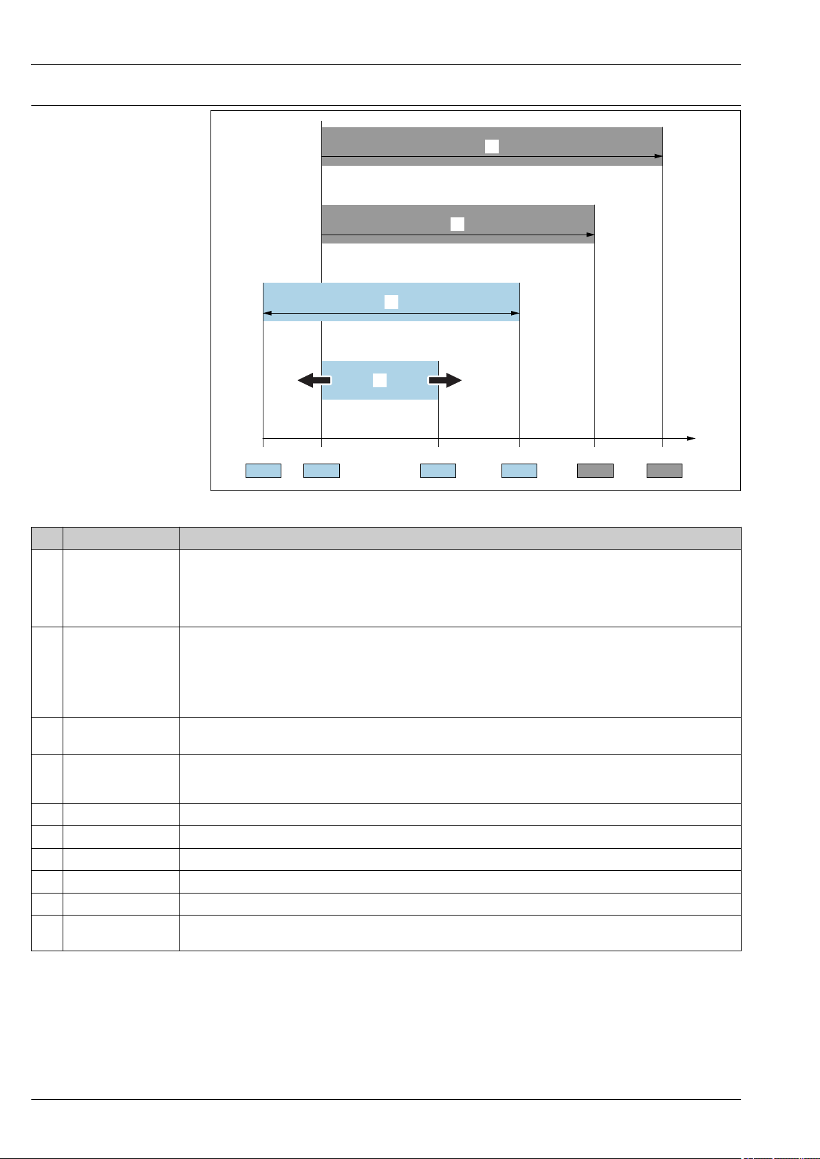
Item Term/abbreviation Explanation
1 OPL The OPL (over pressure limit = sensor overload limit) for the measuring device depends on the lowest-rated element,
with regard to pressure, of the selected components, i.e. the process connection has to be taken into consideration in
addition to the measuring cell. Also observe pressure-temperature dependency. For the relevant standards and
additional notes see the → 32 section.
The OPL may only be applied for a limited period of time.
2 MWP The MWP (maximum working pressure) for the sensors depends on the lowest-rated element, with regard to
pressure, of the selected components, i.e. the process connection has to be taken into consideration in addition to the
measuring cell. Also observe pressure-temperature dependency. For the relevant standards and additional notes see
the → 32 section.
The MWP may be applied at the device for an unlimited period.
The MWP can also be found on the nameplate.
3 Maximum sensor
measuring range
4 Calibrated/adjusted
span
p - Pressure
- LRL Lower range limit
- URL Upper range limit
- LRV Lower range value
- URV Upper range value
- TD (Turn down) Turn down
Span between LRL and URL
This sensor measuring range is equivalent to the maximum calibratable/adjustable span.
Span between LRV and URV
Factory setting: 0 to URL
Other calibrated spans can be ordered as customized spans.
Example - see the following section.
6 Endress+Hauser
Page 7

Deltabar M PMD55
LRV
URLURV
LRL
1 = 2
3
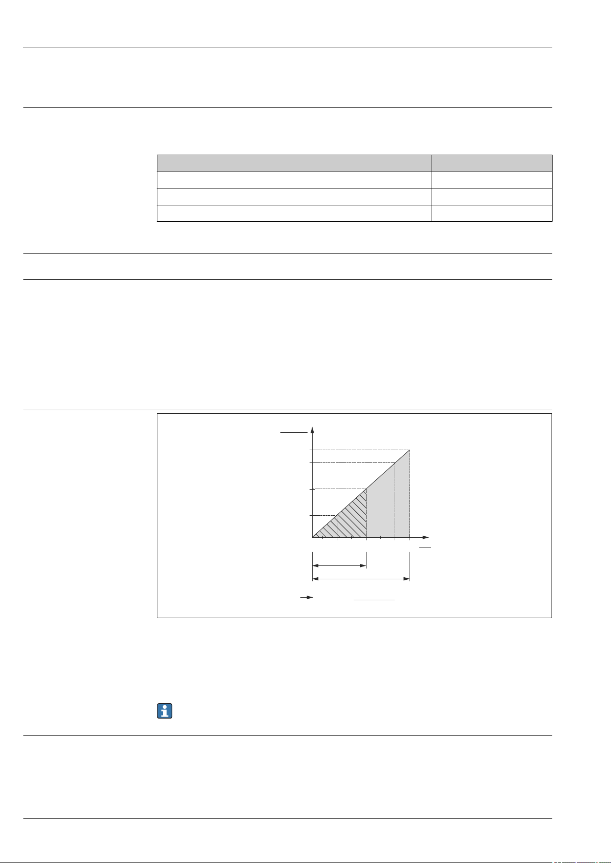
Turn down calculation
1 Calibrated/adjusted span
2 Zero point-based span
3 URL sensor
Example
• Sensor:10 bar (150 psi)
• Upper range value (URL) = 10 bar (150 psi)
Turn down (TD):
A0029545
• Calibrated/adjusted span: 0 to 5 bar (0 to 75 psi)
• Lower range value (LRV) = 0 bar (0 psi)
• Upper range value (URV) = 5 bar (75 psi)
TD =
URL
|URV - LRV|
10 bar (150 psi)
TD =
|5 bar (75 psi) - 0 bar (0 psi)|
In this example, the TD is 2:1.
This span is based on the zero point.
= 2
Endress+Hauser 7
Page 8
Function and system design
p
2
p
1
1
2
3
44
+
–
h
PMD55, H1
+
–
h
PMD55, H2
h =
Dp
r g
+
–
h
PMD55, V1
h =
Dp
r g
h =
Dp
r g
A B C
Measuring principle Metallic process isolating diaphragm
1 Sensing element
2 Overload diaphragm/Middle diaphragm
3 Filling oil
4 Process isolating diaphragm
The metal separating diaphragms (4) are deflected on both sides by the acting pressures p1 and p2.
A filling oil (3) transfers the pressure to a resistance circuit bridge (semiconductor technology). The
differential- pressure-dependent change of the bridge output voltage is measured and further
processed.
Deltabar M PMD55
A0023919
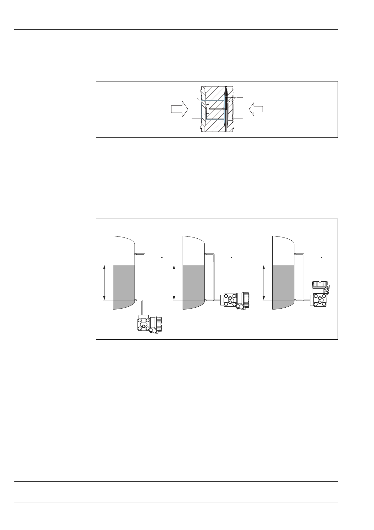
Level measurement (level, volume and mass)
A0023082
A Option V1; vertical impulse line; 90° alignment
B Option H1; horizontal impulse line; 180° alignment
C Option H2; horizontal impulse line; 90° alignment
h Height (level)
Δp Differential pressure
ρ Density of the medium
g Gravitation constant
Your benefits
Flow measurement
8 Endress+Hauser
• Volume and mass measurements in any tank shapes by means of a freely programmable
characteristic curve
• Choice of diverse level units
• Has a wide range of uses, even in the following cases:
• for level measurement in tanks with superimposed pressure
• in the event of foam formation
• in tanks with agitators of screen fittings
• in the event of liquid gases
• for standard level measurement
Flow measurement with Deltabar M PMD55 and primary element
Page 9
Deltabar M PMD55
QQ
p
1
p
2
Q ~
D p
+
+
––
1 1
2 2
p1p
2
Q ~
D p
A B
PMD55, V1
PMD55, V1
PMD55, H1
A B C
A Orifice plate
B Pitot tube
1 Deltabar M
2 3-valve manifold
Q Flow
Δp Differential pressure, Δp = p1 – p
A0023086
2
Your benefits
• Choice between five flow modes of operation:
• Volume flow
• Norm volume flow (European norm conditions)
• Standard volume flow (American standard conditions)
• Mass flow
• %
• Choice of diverse flow units with automatic unit conversion.
• Low flow cut off: when activated, this function suppresses small flows which can lead to large
fluctuations in the measured value.
• Contains two totalizers as standard. One totalizer can be reset to zero.
• The totalizing unit can be individually set for each totalizer. This allows independent daily and
annual quantity totalizing.
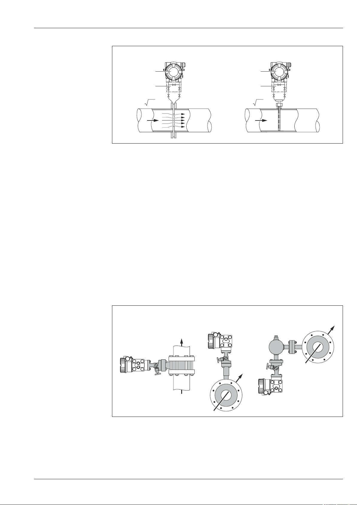
Typical arrangements for flow measurements
Endress+Hauser 9
A Liquid in vertical pipe; H1 option; horizontal impulse line; 180° alignment
B Gas in horizontal pipe; V1 option; vertical impulse line; 90° alignment
C Vapour in horizontal pipe; V1 option; vertical impulse line; 90° alignment
A0023088
Page 10
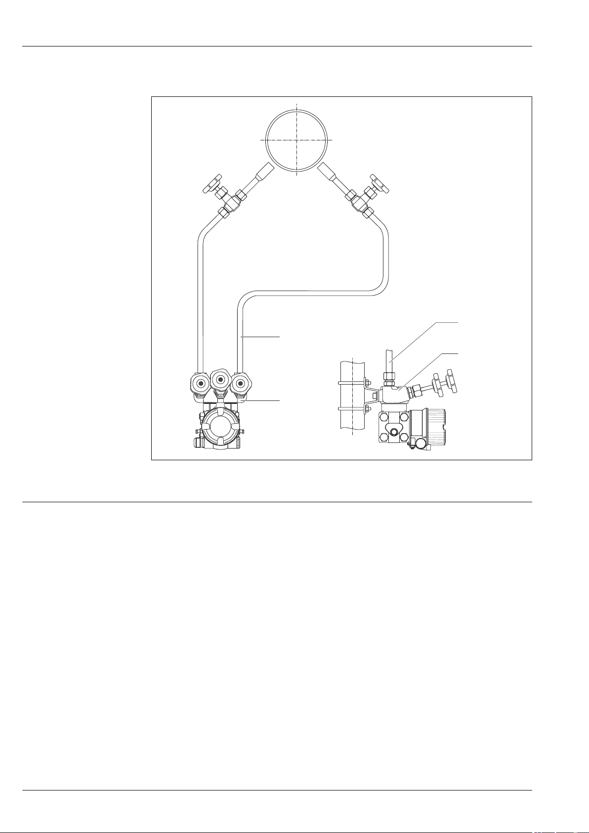
Mounting example
PMD55, V1
2
2
1
1
PMD55, V1
Deltabar M PMD55
Communication protocol
A0023089
1 Valve manifold
2 Impulse line
• 4 to 20 mA with HART communication protocol
• PROFIBUS PA
• The Endress+Hauser devices meet the requirements of the FISCO model.
• Due to a low current consumption of 11 mA ± 1 mA, the following number of devices can be
operated on one bus segment if installing as per FISCO: up to 8 devices for Ex ia, CSA IS and FM
IS applications or up to 31 devices for all other applications e.g. in non-hazardous areas, Ex nA
etc. Further information on PROFIBUS PA can be found in Operating Instructions BA00034S
"PROFIBUS DP/PA: Guidelines for planning and commissioning" and in the PNO Guideline.
• FOUNDATION Fieldbus
• The Endress+Hauser devices meet the requirements of the FISCO model.
• Due to a low current consumption of 16 mA ± 1 mA, the following number of devices can be
operated on one bus segment if installing as per FISCO: up to 6 devices for Ex ia, CSA IS and FM
IS applications or up to 22 devices for all other applications e.g. in non-hazardous areas, Ex nA
etc. Further information on FOUNDATION Fieldbus, such as requirements for bus system
components, can be found in Operating Instructions BA00013S "FOUNDATION Fieldbus
Overview".
10 Endress+Hauser
Page 11
Deltabar M PMD55
Input
Measured variable Measured process variables
Differential pressure, from which flow (volume or mass current) and level (level, volume or mass) are
derived
Measuring range
Sensor Maximum sensor measuring
range
lower (LRL) upper (URL) on one side on both sides
[mbar
[mbar (psi)] [mbar (psi)] [mbar (psi)] [bar (psi)] [bar (psi)] [bar (psi)] [mbar
Smallest
calibratable
measuring span
(preset at the
1)
factory)
MWP OPL Min. operating
pressure
abs
2)
(psi
abs
Option
)]
(psi)]
10 (0.15) –10 (-0.15) +10 (+0.15) 0.5 (0.0075) 1 (15)
4)
1 (15)
4)
1.5 (22.5)
4)
0.1 (0.0015)
4)
7B
30 (0.45) –30 (-0.45) +30 (+0.45) 1.5 (0.0225) 7C
100 (1.5) –100 (-1.5) +100 (+1.5) 5 (0.075) 70 (1050)
500 (7.5) –500 (-7.5) +500 (+7.5) 25 (0.375) 7F
160 (2400)
5)
6)
70 (1050)
160 (2400)
5)
6)
105 (1575)
240 (3600)
5)
6)
7D
1000 (15) -1000 (– 15) +1000 (+ 15) 50 (0.75) 7G
3000 (45) –3000 (-45) +3000 (+45) 150 (2.25) 7H
16000
(240)
40000
(600)
–16000 (-240) +16000
(+240)
–40000 (-600) +40000
(+600)
800 (12) 7L
2000 (30) 7M
0.1 (0.0015)
0.1 (0.0015)
5)
6)
1) Recommended Turn down: Max 100:1. Factory calibration Turn down: Max 20:1
2) The minimum operating pressure indicated in the table applies to silicone oil under reference operating conditions. Minimum operating pressure
at 85°C (185°F) for silicone oil: 10 mbar (0.15 psi) (abs)
3) Product Configurator, "Sensor Nominal Value" ordering feature
4) Option "2" in the Order Code - Feature 60
5) Option "6" in the Order Code - Feature 60
6) Option "7" in the Order Code - Feature 60
3)
Nominal Pressure PN Option
1 bar / 100 kPa/ 14.5 psi 2
70 bar / 7 MPa / 1015 psi 6
160 bar / 16 MPa / 2400 psi 7
1) Product Configurator "Nominal Pressure PN" ordering feature
1)
Endress+Hauser 11
Page 12
Output
U – 11.5 V
23 mA
[ ]W
30
20
11.5
40 45
1239
1456
804
369
£
U
[V]
1
2
R
L
max
3
R
L
max
Deltabar M PMD55
Output signal
Signal range 4 to 20 mA
Signal on alarm
• 4 to 20 mA with superimposed digital communication protocol HART 6.0, 2-wire
• Digital communication signal PROFIBUS PA (Profile 3.02)
• Digital communication signal FOUNDATION Fieldbus
Output Option
4 to 20mA HART 2
PROFIBUS PA 3
FOUNDATION Fieldbus 4
1) Product Configurator, "Output" ordering feature
4 to 20 mA HART: 3.8 to 20.5 mA
As per NAMUR NE 43
• 4 to 20 mA HART:
Options:
• Max. alarm: can be set from 21 to 23 mA (factory setting: 22 mA)
• Hold measured value: last measured value is held
• Min. alarm: 3.6 mA
• PROFIBUS PA: can be set in the Analog Input block
Options: Last Valid Out Value (factory setting), Fail-safe Value, Status Bad
• FOUNDATION Fieldbus: can be set in the Analog Input block
Options: Last Good Value, Fail-safe Value (factory setting), Wrong Value
1)
Load - 4...20 mA HART
A0023090
1 Supply voltage 11.5 to 30 V DC for intrinsically safe device versions (not for analog)
2 Supply voltage 11.5 to 45 V DC (versions with plug-in connector 35 V DC) for other types of protection and
for uncertified device versions
3 R
U Supply voltage
Maximum load resistance
Lmax
When operating via a handheld terminal or via a PC with an operating program, a minimum
communication resistance of 250 Ω must be taken into account.
Damping
A damping affects all outputs (output signal, display):
• Via on-site display, handheld terminal or PC with operating program, continuous from 0...999 s
• Via DIP-switch on the electronic insert, switch position
"on" (= set value) and "off" (= damping switched off)
• Factory setting: 2 s
12 Endress+Hauser
Page 13

Deltabar M PMD55
Firmware version
Protocol-specific data HART
Designation Option
01.00.zz, FF, DevRev01 76
01.00.zz, PROFIBUS PA, DevRev01 77
01.00.zz, HART, DevRev01 78
1) Product Configurator, "Firmware version" ordering feature
Manufacturer ID 17 (11 hex)
Device Type Code 23 (17 hex)
Device Revision 01 (01 hex) - SW version 01.00.zz
HART specification 6
DD Revision • 01 (Dutch))
• 02 (Russian))
Device description files (DTM, DD) Information and files can be found:
• www.endress.com
• www.fieldcommgroup.org
HART load Min. 250 Ω
HART device variables The measured values can be freely assigned to the device variables:
Measured values for PV (primary variable)
• Pressure
• Flow
• Level
• Tank content
Measured values for SV, TV (second and third variable)
• Pressure
• Totalizer
• Level
Supported functions • Burst mode
• Additional Transmitter Status
• Device Locking
• Alternative operating modes
1)
Wireless HART data
Protocol-specific data PROFIBUS PA
Minimum starting voltage 11.5 V
Start-up current 12 mA (default) or 22 mA (customer setting)
Starting time 5 s
Minimum operating voltage 11.5 V
Multidrop current 4 mA
Time for connection setup 1 s
1) Or higher if operating near ambient temperature limits (–40 to +85 °C (–40 to +185))
Manufacturer ID 17 (11 hex)
Ident number 1542 hex
Profile Version 3.02
SW Version 01.00.zz
GSD Revision 5
DD Revision 1
GSD File Information and files can be found:
DD Files
• www.endress.com
• www.profibus.org
1)
1)
Endress+Hauser 13
Page 14
Deltabar M PMD55
Output values Measured values for PV (via Analog Input Function Block)
• Pressure
• Level
• Flow
• Tank content
Measured values for SV
Pressure
Measured values for QV
Totalizer
Input values Input value sent from PLC, can be shown on display
Supported functions • Identification & Maintenance
Simple device identification via control system and nameplate
• Condensed status
• Automatic ident number adaptation and switchable to following
ident numbers:
• 9700: Profile-specific transmitter identification number with the
"Classic" or "Condensed" status.
• 1554: Identification number for Deltabar M
• Device locking: The device can be locked by hardware or software.
Protocol-specific data FOUNDATION Fieldbus
Device Type 0x1021
Device Revision 01 (hex)
DD Revision 0x01021
Device description files (DTM, DD) Information and files can be found:
• www.endress.com
• www.fieldcommgroup.org
CFF Revision 0x000102
ITK Version 5.2.0
ITK-Certification Driver-No. IT067600
Link-Master (LAS) capable yes
Link Master / Basic Device selectable Yes; Factory setting: Basic Device
Number of VCRs 44
Number of Link Objects in VFD 50
Number of FB-Schedule Objects 40
Virtual communication references (VCRs)
Permanent Entries 44
Client VCRs 0
Server VCRs 5
Source VCRs 8
Sink VCRs 0
Subscriber VCRs 12
Publisher VCRs 19
Link settings
Slot time 4
Min. Inter PDU delay 12
Max. response delay 40
14 Endress+Hauser
Page 15
Deltabar M PMD55
Transducer Blocks
Block Content Output values
TRD1 Block Contains all parameters related to the
measurement
Dp Flow Block Contains flow and totalizer parameters • Totalizer 1 (channel 6)
Diagnostic Block Contains diagnostic information Error code via DI channels (channel 10 to 15)
Display Block Contains parameters to configure the onsite
display
• Pressure, Flow or level (channel 1)
• Process temperature (channel 2)
• Measured pressure value (channel 3)
• Max. pressure (channel 4)
• Level before linearization (channel 5)
• Totalizer 2 (channel 7)
No output values
Function blocks
Block Content Number
of blocks
Resource Block The Resource Block contains all the data that uniquely identify the device. It is an
electronic version of a nameplate of the device.
Analog Input
Block 1
Analog Input
Block 2
Digital Input
Block
Digital Output
Block
PID Block The PID Block serves as a proportional-integralderivative controller and is used almost
Arithmetic Block This block is designed to permit simple use of popular measurement math functions. The
Input Selector
Block
Signal
Characterizer
Block
Integrator Block The Integrator Block integrates a variable as a function of the time or accumulates the
The AI Block receives the measuring data from the Sensor Block, (selectable via a
channel number) and makes the data available to other function blocks at its output.
Enhancement: digital outputs for process alarms, fail safe mode.
This block contains the discrete data of the Diagnose Block (selectable via a channel
number 10 to 15) and provides them for other blocks at the output.
This block converts the discrete input and thus initiates an action (selectable via a
channel number) in the DP Flow Block or in the im TRD1 Block. Channel 20 resets the
counter for max. pressure transgressions value and Channel 21 resets the Totalizer.
universally for closed-loop-control in the field including cascade and feedforward. Input
IN can be indicated on the display. The selection is performed in the Display Block
(DISPLAY_MAIN_LINE_CONTENT).
user does not have to know how to write equations. The math algorithm is selected by
name, chosen by the user for the function to be performed.
The Input Selector Block facilitates the selection of up to four inputs and generates an
output based on the configured action. This block normally receives its inputs from AI
Blocks. The block performs maximum, minimum, average and ‘first good’ signal
selection. Inputs IN1 to IN4 can be indicated on the display. The selection is performed
in the Display Block (DISPLAY_MAIN_LINE_1_CONTENT).
DThe Signal Characterizer Block has two sections, each with an output that is a nonlinear function of the respective input. The non-linear function is generated by a single
look-up table with 21 arbitrary x-y pairs.
counts from a Pulse Input Block. The block may be used as a totalizer that counts up
until reset or as a batch totalizer that has a setpoint, where the integrated or
accumulated value is compared to pre-trip and trip settings, generating a binary signal
when the setpoint is reached.
1 enhanced
2 25 ms enhanced
1 20 ms standard
1 20 ms standard
1 40 ms standard
1 35 ms standard
1 30 ms standard
1 40 ms standard
1 35 ms standard
Execution
time
Functionality
Additional function block information:
Instantiate Function Block YES
Number of additional instantiatable function blocks 20
Endress+Hauser 15
Page 16

Terminal assignment
- +
1
2
3
4
5
6
7
Deltabar M PMD55
Power supply
WARNING
L
An incorrect connection compromises electrical safety!
When using the measuring device in hazardous areas, the relevant national standards and
‣
regulations as well as the Safety Instructions or Installation or Control Drawings must be
observed → 53.
All explosion protection data are given in separate documentation which is available upon
‣
request. The Ex documentation is supplied as standard with all Ex-systems → 53.
In accordance with IEC/EN61010 a suitable circuit breaker must be provided for the device.
‣
HART: Overvoltage protection HAW569-DA2B for the non-hazardous area, ATEX II 2 (1) Ex ia
‣
IIC and IEC Ex ia can be ordered as an option (see the "Ordering information" section).
Protective circuits against reverse polarity, HF influences and overvoltage peaks are installed.
‣
1 External grounding terminal (only for devices with certainly approvals or if "Measuring point" (TAG) is
2 Internal grounding terminal
3 Supply voltage → 16
4 4...20 mA for HART devices
5 For HART and FOUNDATION Fieldbus devices: With a handheld terminal, all the parameters can be
6 Terminals
7 For HART devices: test terminals, see section "Taking 4 to 20 mA test signal" → 16
Supply voltage 4 to 20 mA HART
Type of protection Supply voltage
Intrinsically safe 11.5 to 30 V DC
• Other types of protection
• Devices without certificate
Taking 4 to 20 mA test signal
A 4 to 20 mA test signal may be measured via the test terminals without interrupting the
measurement.
PROFIBUS PA
Version for non-hazardous areas: 9 to 32 V DC
A0023505
ordered)
configured anywhere along the bus line via menu operation.
11.5 to 45 V DC
(versions with plug-in connection 35 V DC)
16 Endress+Hauser
Page 17
Deltabar M PMD55
FOUNDATION Fieldbus
Version for non-hazardous areas: 9 to 32 V DC
Current consumption
Electrical connection
• PROFIBUS PA: 11 mA ±1 mA, switch-on current corresponds to IEC 61158-2, Clause 21
• FOUNDATION Fieldbus: 16 mA ±1 mA, switch-on current corresponds to IEC 61158-2, Clause 21
Cable entry Degree of protection Option
M20 gland IP66/67 NEMA 4X/6P A
M20 thread IP66/67 NEMA 4X/6P B
G ½" thread IP66/67 NEMA 4X/6P C
NPT ½" thread IP66/67 NEMA 4X/6P D
M12 plug IP66/67 NEMA 4X/6P I
7/8" plug IP66/67 NEMA 4X/6P M
HAN7D plug 90 deg IP65 P
M16 valve connector IP64 V
1) Product Configurator, order code for "Electrical connection"
1)
PROFIBUS PA
The digital communication signal is transmitted over the bus via a 2-wire connection. The bus also
provides the power supply. For further information on the network structure and grounding, and for
further bus system components such as bus cables, see the relevant documentation, e.g. Operating
Instructions BA00034S "PROFIBUS DP/PA: Guidelines for planning and commissioning" and the PNO
Guideline.
Terminals
Cable entry
FOUNDATION Fieldbus
The digital communication signal is transmitted over the bus via a 2-wire connection. The bus also
provides the power supply. For further information on the network structure and grounding and for
further bus system components such as bus cables, see the relevant documentation, e.g. Operating
Instructions BA00013S "FOUNDATION Fieldbus Overview" and the FOUNDATION Fieldbus Guideline.
• Supply voltage and internal ground terminal: 0.5 to 2.5 mm2 (20 to 14 AWG)
• External ground terminal: 0.5 to 4 mm2 (20 to 12 AWG)
Approval Type Clamping area
Standard, II1/2G Exia, IS Plastic M20x1.5 5 to 10 mm (0.2 to 0.39 in)
ATEX II1/2D, II1/2GD Exia, II3G Ex nA Metal M20x1.5 (Ex e) 7 to 10.5 mm (0.28 to 0.41 in)
For other technical data, see the housing section
Endress+Hauser 17
Page 18
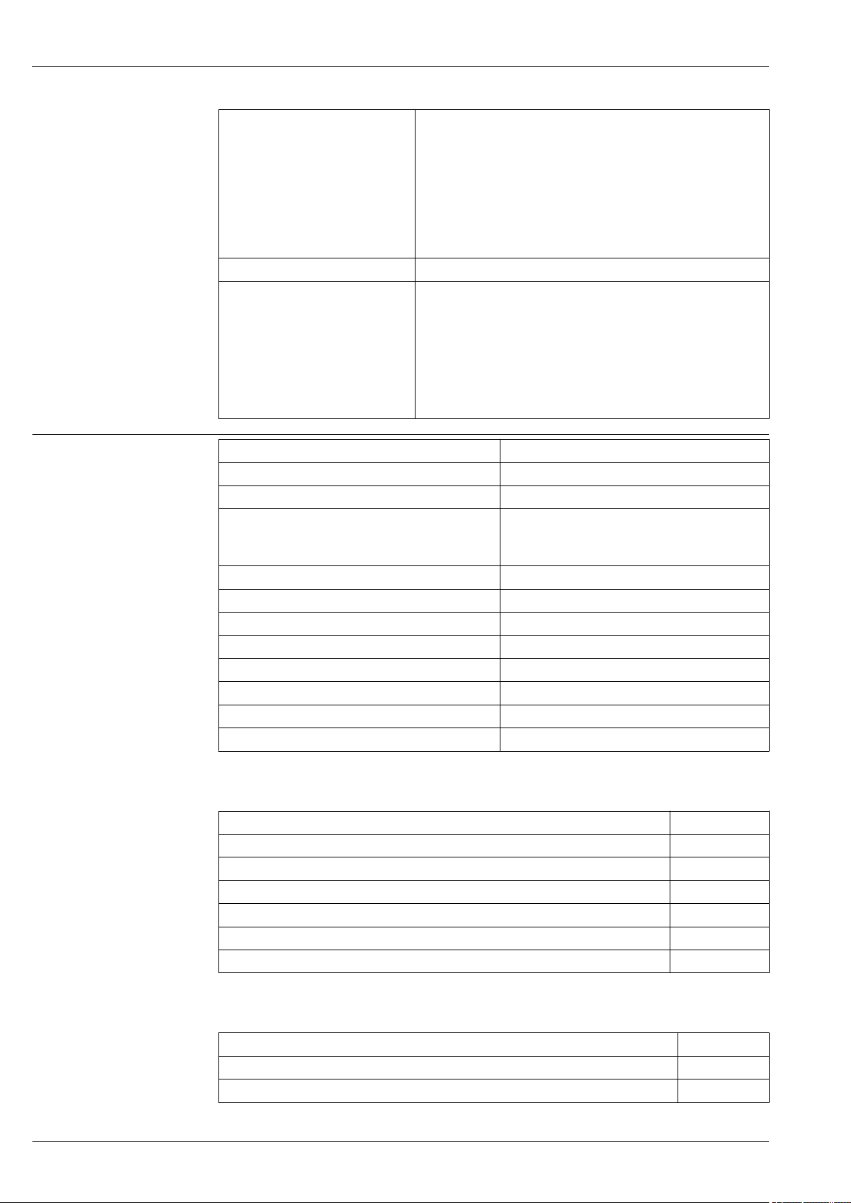
Device plugs Devices with valve connector (HART)
+
2 1
–
+
A B
BU BN GNYE
2
1
3
+
–
–
Han7D
+ –
–
+
A B
2
1
34
1 BN = brown, BU = blue, GNYE = green
A Electrical connection for devices with valve connector
B View of the plug connector at the device
Material: PA 6.6
Deltabar M PMD55
A0023097
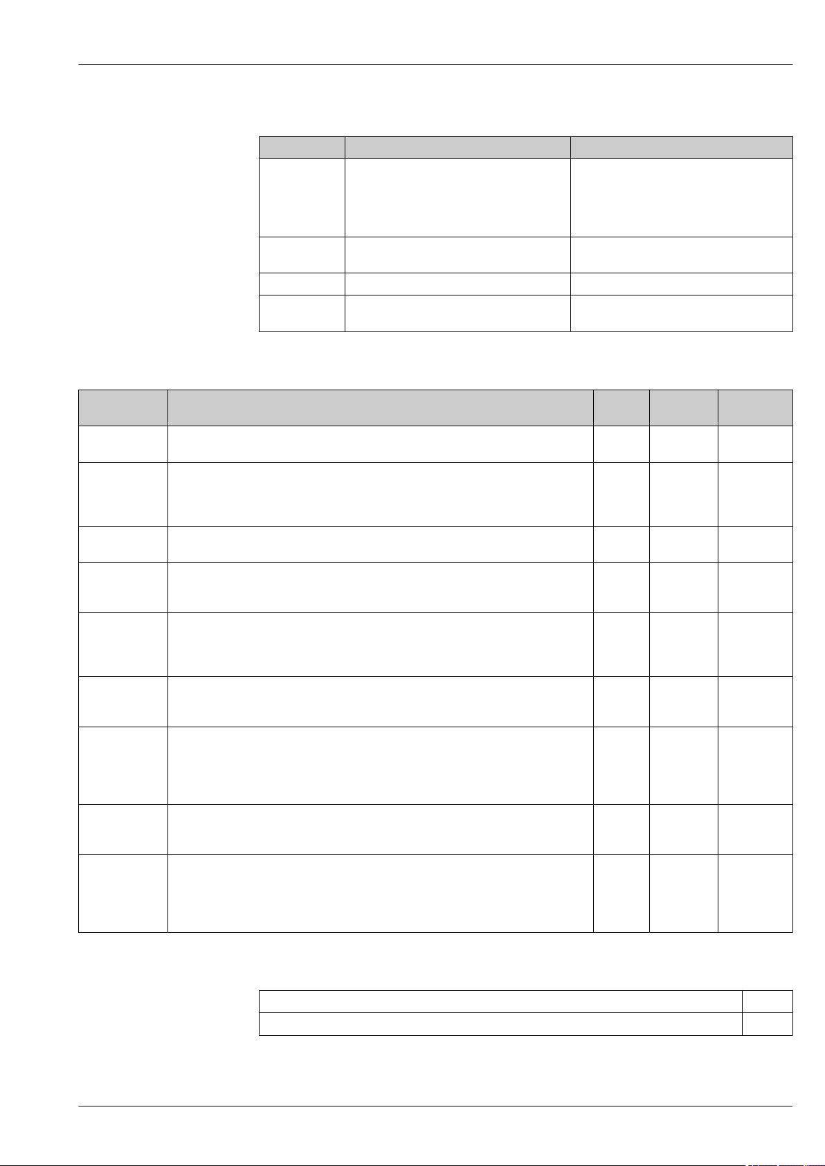
Devices with Harting plug Han7D (HART)
A Electrical connection for devices with Harting plug Han7D
B View of the plug-in connector at the device
Material: CuZn, contacts for plug-in jack and connector are gold-plated
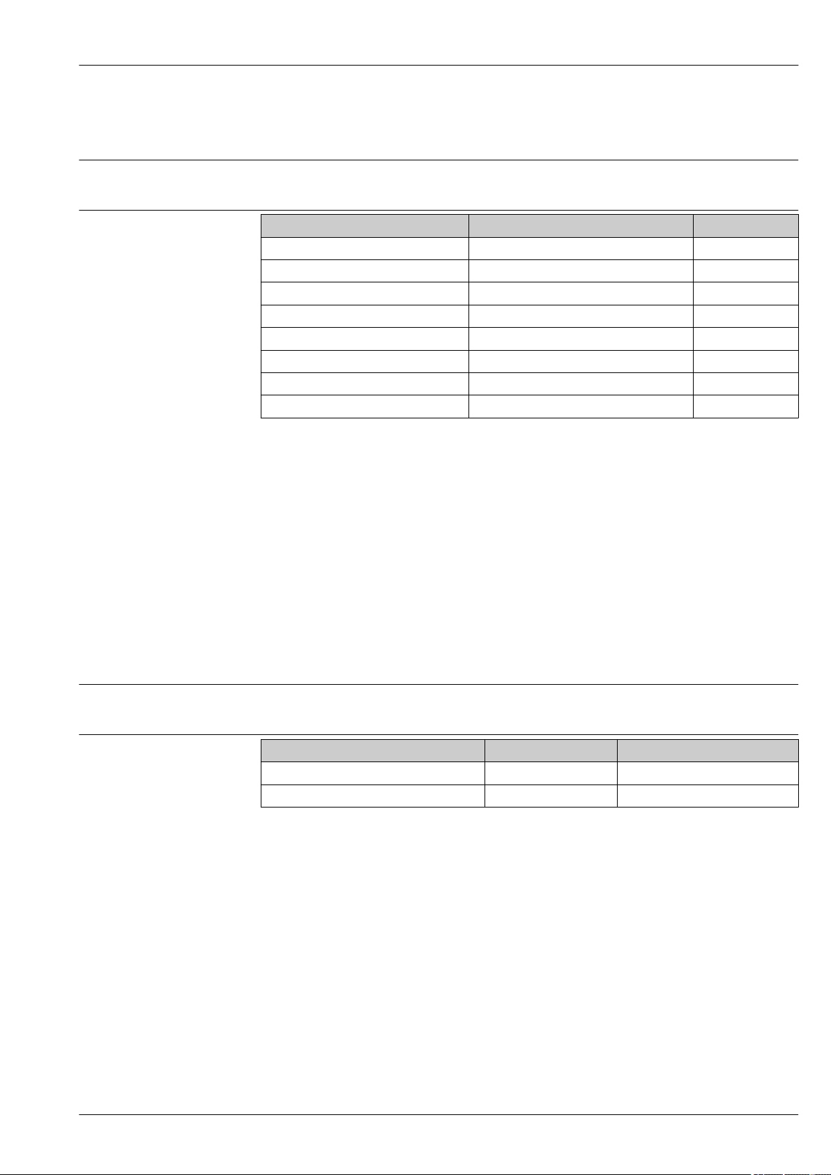
Devices with M12 plug(Analog, HART, PROFIBUS PA)
A0019990
1 Signal +
2 Not assigned
3 Signal –
4 Ground
Endress+Hauser offers the following accessories for devices with an M12 plug:
18 Endress+Hauser
A0011175
Page 19

Deltabar M PMD55
4
2
3
1
Plug-in jack M 12x1, straight
• Material: body PA; coupling nut CuZn, nickel-plated
• Degree of protection (fully locked): IP66/67
• Order number: 52006263
Plug-in jack M 12x1, elbowed
• Material: body PBT/PA; coupling nut GD-Zn, nickel-plated
• Degree of protection (fully locked): IP66/67
• Order number: 71114212
Cable 4x0.34 mm2 (20 AWG) with M12 socket, elbowed, screw plug, length 5 m (16 ft)
• Material: body PUR; coupling nut CuSn/Ni; cable PVC
• Degree of protection (fully locked): IP66/67
• Order number: 52010285
Devices with 7/8" plug (Analog, HART, FOUNDATION Fieldbus)
1 Signal 2 Signal +
3 Not assigned
4 Shield
External thread: 7/8 - 16 UNC
• Material: 316L (1.4401)
• Protection: IP66/68
Cable specification HART
• Endress+Hauser recommends using twisted, shielded two-wire cables.
• The cable outer diameter depends on the cable entry used.
PROFIBUS PA
Use a twisted, shielded two-wire cable, preferably cable type A
FOUNDATION Fieldbus
Use a twisted, shielded two-wire cable, preferably cable type A
A0011176
For further information on the cable specifications, see Operating Instructions BA00034S
"PROFIBUS DP/PA: Guidelines for planning and commissioning", the PNO Guideline 2.092
PROFIBUS PA User and Installation Guideline" and IEC 61158-2 (MBP).
For further information on the cable specifications, see Operating Instructions BA00013S
"FOUNDATION Fieldbus Overview", FOUNDATION Fieldbus Guideline and IEC 61158-2 (MBP).
Start-up current
Residual ripple
12 mA or 22 mA (selectable)
No influence on 4 to 20 mA signal up to ±5 % residual ripple within the permitted voltage range
[according to HART hardware specification HCF_SPEC-54 (DIN IEC 60381-1)].
Influence of power supply
Overvoltage protection (optional)
≤0.001 % of URV/V
The device can be fitted with overvoltage protection. The overvoltage protection is mounted at the
factory on the housing thread (M20x1.5) for the cable gland and is approx. 70 mm (2.76 in) in
length (take additional length into account when installing). The device is connected as illustrated in
the following graphic.
For details refer to TI01013KDE, XA01003KA3 and BA00304KA2.
Endress+Hauser 19
Page 20

Ordering information:
1
2
3
4
+
-
+
-
rt
sw
+
-
A
B
Product Configurator, "Mounted accessories" ordering feature, option NA
Wiring
A Without direct shield grounding
B With direct shield grounding
1 Incoming connection cable
2 HAW569-DA2B
3 Unit to be protected
4 Connection cable
Deltabar M PMD55
A0023111
20 Endress+Hauser
Page 21

Deltabar M PMD55
Performance characteristics
Response time HART
• Acyclic: min. 330 ms, typically 590 ms (depending on command # and number of preambles)
• Cyclic (burst): min. 160 ms, typically 350 ms (depending on command # and number of
preambles)
PROFIBUS PA
• Acyclic: approx. 23 ms to 35 ms (depending on Min. Slave Interval)
• Cyclic: approx. 8 ms to 13 ms (depending on Min. Slave Interval)
FOUNDATION Fieldbus
• Acyclic: typically 70 ms (for standard bus parameter settings)
• Cyclic: max. 20 ms (for standard bus parameter settings)
Reference operating conditions
Maximum measured error (total performance)
• As per IEC 60770-1 and IEC 61298-1, Sections 5 to 7
• Ambient temperature TA = constant, in the range of +21 to +33 °C (+70 to +91 °F)
•
Humidity j = constant, in the range: 5 to 80 % RH ± 5 %
• Ambient pressure pA = constant, in the range: 860 to 1 060 mbar (12.47 to 15.37 psi)
• Position of the measuring cell: constant, in range: ±1° horizontally and ±1° vertically
• P1 = high pressure side
• Input of "Lo Trim Sensor" and "Hi Trim Sensor" for lower range value and upper range value
• Measuring span URV - LRV
• Membrane material 316L
• Filling oil: silicone oil
• Side flanges material: AISI 316L
• Supply voltage: 24 V DC ±3 V DC
• Load with HART: 250 Ω
The performance characteristics refer to the accuracy of the measuring device. The factors
influencing accuracy can be divided into two groups
• Total performance of measuring device
• Installation factors
All performance characteristics are in conformance with ≥ ± 3 sigma.
The total performance of the measuring device comprises the reference accuracy and the ambient
temperature effect and is calculated using the following formula:
Total performance = ± √ ( (E1)² + (E2)² + (E3)²)
E1 = Reference accuracy
E2 = Temperature effect per ±28 °C (50 °F)
(corresponds to the range from –3 to +53 °C (+27 to +127 °F))
Calculation of E2:
E2 = E2M + E2
E2M = Main temperature error
E2E = Electronics error
E3 = Static pressure effect
• The values apply for process isolating diaphragm made of 316L (1.4435)
• The values refer to the calibrated span
E
Endress+Hauser 21
Page 22

Deltabar M PMD55
Reference accuracy [E1]
Reference accuracy comprises the non-linearity [IEC 62828-1 / DIN EN 61298-2] including the
hysteresis [IEC 62828-1 / DIN EN 61298-2] and the non-repeatability [IEC 62828-1 / DIN EN
61298-2] in accordance with the limit point method as per [IEC 62828-1 / DIN EN 60770-2].
10 mbar (0.15 psi) and 30 mbar (0.45 psi) sensor
• Standard: TD 1:1 = ±0.2 %; TD > 1:1 = ±0.2 % · TD
• Platinum: 100 mbar (1.5 psi) sensor
• Standard: TD 1:1 to TD 4:1 = ±0.1 %; TD > 4:1 = ±(0.012 % · TD + 0.052 %)
• Platinum: TD 1:1 to TD 4:1 = ±0.075 %; TD > 4:1 = ±(0.012 % · TD + 0.027 %)
500 mbar (7.5 psi), 1 bar (15 psi), 3 bar (45 psi), 16 bar (240 psi) and 40 bar (600 psi) sensor
• Standard: TD 1:1 to TD 10:1 = ±0.1 %; TD > 10:1 = ±(0.0015 % · TD + 0.085 %)
• Platinum: TD 1:1 to TD 10:1 = ±0.075 %; TD > 10:1 = ±(0.0015 % · TD + 0.060 %)
Temperature effect [E2]
E2M - Main temperature error
The output changes due to the effect of the ambient temperature [IEC 62828-1 / IEC 61298-3] with
respect to the reference temperature [IEC 62828-1 / DIN 16086]. The values specify the maximum
error due to min./max. ambient or process temperature conditions.
10 mbar (0.15 psi) and 30 mbar (0.45 psi) sensor
• Standard: ±(0.31 % · TD + 0.5 %)
• Platinum: 100 mbar (1.5 psi) sensor
• Standard: ±(0.18 % · TD + 0.02 %)
• Platinum: ±(0.18 % · TD + 0.02 %)
500 mbar (7.5 psi), 1 bar (15 psi) and 3 bar (45 psi) sensor
• Standard: ±(0.08 % · TD + 0.05 %)
• Platinum: ±(0.08 % · TD + 0.05 %)
16 bar (240 psi) sensor
• Standard: ±(0.1 % · TD + 0.1 %)
• Platinum: ±(0.1 % · TD + 0.1 %)
40 bar (600 psi) sensor
• Standard: ±(0.08 % · TD + 0.05 %)
• Platinum: ±(0.08 % · TD + 0.05 %)
E2E - Electronics error
• Analog output (4 to 20 mA): 0.2 %
• Digital output (HART/PA/FF): 0 %
E3M - Main static pressure error
The static pressure effect refers to the effect on the output due to changes in the static pressure of
the process (difference between the output at each static pressure and the output at atmospheric
pressure [IEC 62828-2 / IEC 61298-3] and therefore the combination of the influence of the
operating pressure on the zero point and the span).
10 mbar (0.15 psi) sensor
Standard
• Influence on the zero point: ± 0.20 % · TD per 1 bar (14.5 psi)
• Influence on the span: ± 0.20 % per 1 bar (14.5 psi)
30 mbar (0.45 psi) sensor
Standard
• Influence on the zero point: ± 0.07 % · TD per 1 bar (14.5 psi)
• Influence on the span: ± 0.07 % per 1 bar (14.5 psi)
22 Endress+Hauser
Page 23

Deltabar M PMD55
100 mbar (1.5 psi) sensor
• Standard
• Influence on the zero point: ± 0.15 % · TD per 70 bar (1 015 psi)
• Influence on the span: ± 0.14 % per 70 bar (1 015 psi)
• Platinum
• Influence on the zero point: ± 0.15 % · TD per 70 bar (1 015 psi)
• Influence on the span: ± 0.14 % per 70 bar (1 015 psi)
500 mbar (7.5 psi), 1 bar (15 psi), 3 bar (45 psi), 16 bar (240 psi) and 40 bar (600 psi) sensor
• Standard
• Influence on the zero point: ± 0.075 % · TD per 70 bar (1 015 psi)
• Influence on the span: ± 0.14 % per 70 bar (1 015 psi)
• Platinum
• Influence on the zero point: ± 0.075 % · TD per 70 bar (1 015 psi)
• Influence on the span: ± 0.14 % per 70 bar (1 015 psi)
Calculation of the total performance with the Endress+Hauser Applicator
Detailed measured errors, such as for other temperature ranges, for example, can be calculated with
the Applicator "Sizing Pressure Performance".
Resolution
Total error
A0038927
• Current output: 1 μA
• Display: can be set (factory setting: presentation of the maximum accuracy of the transmitter)
The total error of the measuring device comprises the total performance and the influence of longterm stability and is calculated using the following formula:
Total error = total performance + long-term stability
Calculation of the total error with the Endress+Hauser Applicator
Detailed measured errors, such as for other temperature ranges, for example, can be calculated with
the Applicator "Sizing Pressure Performance".
A0038927
Long-term stability
10 mbar (0.15 psi) and 30 mbar (0.45 psi) sensor
• 1 year: ± 0.25 %
• 5 years: ± 1.25 %
• 10 years: ± 1.50 %
Endress+Hauser 23
Page 24

100 mbar (1.5 psi) sensor
I
63 %
100 %
t
t1t
2
90 %
t
3
• 1 year: ± 0.18 %
• 5 years: ± 0.35 %
• 10 years: ± 0.50 %
500 mbar (7.5 psi), 1 bar (15 psi), 3 bar (45 psi), 16 bar (240 psi) and 40 bar (600 psi) sensor
• 1 year: ± 0.05 %
• 5 years: ± 0.13 %
• 10 years: ± 0.23 %
Response time T63 and T90 Dead time, time constant
Presentation of the dead time and the time constant:
Deltabar M PMD55
Dynamic behavior, current output (HART electronics)
Dead time (t1) Time constant T63 (= t2) Time constant T90 (= t3)
Max. 60 ms 90 ms 210 ms
Dynamic behavior, digital output (HART electronics)
Dead time (t1) Dead time (t1) +
Time constant T63 (= t2)
Min. 220 ms 310 ms 370 ms
Max. 1020 ms 1110 ms 1170 ms
Dead time (t1) +
Time constant T90 (= t3)
Reading cycle
• Acyclic: max. 3/s, typical 1/s (depends on command # and number of preambles)
• Cyclic (burst): max. 3/s, typical 2/s
The device commands the BURST MODE function for cyclic value transmission via the HART
communication protocol.
Cycle time (update time)
Cyclic (burst): min. 300 ms
A0019786
Dynamic behavior, PROFIBUS PA
Dead time (t1) Dead time (t1) +
Time constant T63 (= t2)
Min. 95 ms 185 ms 245 ms
Max. 1195 ms 1285 ms 1345 ms
Dead time (t1) +
Time constant T90 (= t3)
24 Endress+Hauser
Page 25

Deltabar M PMD55
Reading cycle (SPS)
• Acyclic: typically 25/s
• Cyclic: typically 30/s (dependent on the number and type of function blocks used in a closedcontrol loop)
Cycle time (update time)
Min. 100 ms
The cycle time in a bus segment in cyclic data communication depends on the number of devices, on
the segment coupler used and on the internal PLC cycle time.
Dynamic behavior, FOUNDATION Fieldbus
Dead time (t1) Dead time (t1) +
Time constant T63 (= t2)
Min. 105 ms 195 ms 255 ms
Max. 1105 ms 1195 ms 1255 ms
Dead time (t1) +
Time constant T90 (= t3)
Reading cycle
• Acyclic: typically 5/s
• Cyclic: max. 10/s (dependent on the number and type of function blocks used in a closed-control
loop)
Cycle time (update time)
Cyclic: min. 100 ms
Endress+Hauser 25
Page 26

Installation factors Influence of the installation position
0...10°
0...10°
The recommended maximum angle to the axis of the diaphragm is 10° and results in a measuring
error of ±0.72 mbar (0.01 psi). The value is doubled for devices with inert oil.
Position-dependent zero point shift can be corrected → 27.
Vibration effects
Deltabar M PMD55
A0023099
Test standard Vibration effects
GL VI-7-2
• Part 7: Guidelines for the Performance of Type Approvals
• Chapter 2: Test Requirements for Electrical /Electronic Equipment and
Systems
IEC 61298-3
IEC 60068-2-6
Guaranteed for
5 to 25 Hz: ±1.6 mm (0.06 in);
25 to 100 Hz:
4 g in all 3 axes
≤ reference accuracy to 10 to 60 Hz:
±0.35 mm (0.01 in);
60 to 2000 Hz:
5 g in all 3 axes
Warm-up period
• 4 to 20 mA HART: ≤5 s
• PROFIBUS PA: ≤8 s
• FOUNDATION Fieldbus: ≤20 s (after a TOTAL reset ≤45 s)
26 Endress+Hauser
Page 27

Deltabar M PMD55
Installation
General installation instructions
Measuring arrangement Flow measurement
The position-dependent zero point shift can be corrected:
• directly at the device via operating keys on the electronic insert
• directly at the device via operating keys on the display
• via digital communication if the cover is not open.
• Endress+Hauser offers a mounting bracket for installing the device on pipes or walls.
• When measuring in media with solid proportions, such as dirty liquids, installing separators and
drain valves is useful for capturing and removing sediment.
• Using a three-valve or five-valve manifold allows for easy commissioning, installation and
maintenance without interrupting the process.
• General recommendations for the impulse piping can be found in DIN 19210 "Methods for
measurement of fluid flow; differential piping for flow measurement devices" or the corresponding
national or international standards.
• Install the impulse piping with a continuous gradient of at least 10 %.
• When routing the impulse piping outdoors, ensure that sufficient anti-freeze protection is used,
e.g. by using pipe heat tracing.
• Measuring arrangement for gases: Mount device above the measuring point.
• Measuring arrangement for liquids and vapours: Mount the device below the measuring point.
• For flow measurement in vapours, mount the condensate traps at the same level as the same the
tapping point and at the same distance from Deltabar M.
Level measurement
Measuring arrangement level measurement in open tanks
Mount device below the lower measuring connection. The low-pressure side is open to atmosphere
pressure.
Measuring arrangement level measurement in closed tanks and closed tanks with superimposed
vapor
• Mount device below the lower measuring connection. Always connect the low-pressure side above
the maximum level.
• In the case of level measurement in closed tanks with superimposed vapor, a condensate trap
ensures pressure which remains constant on the low-pressure side.
Pressure measurement
• Measuring arrangement for gases: Mount device above the measuring point.
• Measuring arrangement for liquids and vapours: Mount the device below the measuring point.
• For differential pressure measurement in vapor, mount the condensate traps at the same level as
the same the tapping point and at the same distance from Deltabar M.
Endress+Hauser 27
Page 28

Deltabar M PMD55
Wall and pipe-mounting
Endress+Hauser offers the following mounting brackets for installing the device on pipes or walls:
Standard design Heavy-duty version
A0031326 A0031327
The standard mounting bracket version is not suitable for use in an application subject to
vibrations.
The vibration resistance of the heavy-duty version of the mounting bracket has been tested
according to IEC 61298-3, see the "Vibration resistance" section → 31.
When using a valve block, the block's dimensions must be taken into account.
Bracket for wall and pipe mounting including retaining bracket for pipe mounting and two nuts.
Technical data (e.g. dimensions or order numbers for screws) see accessory document
SD01553P/00/EN.
Ordering information:
• Standard design: Product Configurator "Accessory Enclosed" ordering feature, version "PD"
• Heavy-duty version: Product Configurator, order code for "Accessories enclosed" option "PB"
• The adapter plate is part of the delivery if the order option "PB" or "PD" was selected in combination
with the variant V1 or H2 from the process connection.
Wall and pipe-mounting manifold (optional)
A0032335
Technical data (e.g. dimensions or order numbers for screws) see accessory document
SD01553P/00/EN.
Ordering information:
Product Configurator, order code for "Accessories enclosed", option "PJ"
28 Endress+Hauser
Page 29

Deltabar M PMD55
1
1
2
4
3
1
2
3
3
4
C
A
B
4
Typical installation arrangements
A0023109
A Impulse line vertical, version V1, alignment 90°
B Impulse line horizontal, version H1, alignment 180°
C Impulse line horizontal, version H2, alignment 90°
1 Deltabar M
2 Adapter plate
3 Mounting bracket
4 Pressure line
Position Process connection Gland Installation Material Option
A NPT1/4-18 IEC61518 UNF7/16-20 Impulse line vertical, version V1, alignment 90° 1.4408 / CF3M
3)
/ AISI 316L HAJ
1) 2)
NPT1/4-18 IEC61518 UNF7/16-20 Impulse line vertical, version V1, alignment 90° C22.8 HA4
NPT1/4-18 IEC61518 M10 Impulse line vertical, version V1, alignment 90° 1.4408 / CF3M
3)
/ AISI 316L HBJ
NPT1/4-18 IEC61518 M10 Impulse line vertical, version V1, alignment 90° C22.8 HB4
B NPT1/4-18 IEC61518 UNF7/16-20 Impulse line horizontal, version H1, alignment 180° 1.4408 / CF3M
NPT1/4-18 IEC61518 UNF7/16-20 Impulse line horizontal, version H1, alignment 180° C22.8 HG4
NPT1/4-18 IEC61518 M10 Impulse line horizontal, version H1, alignment 180° 1.4408 / CF3M
NPT1/4-18 IEC61518 M10 Impulse line horizontal, version H1, alignment 180° C22.8 HH4
C NPT1/4-18 IEC61518 UNF7/16-20 Impulse line horizontal, version H2, alignment 90° 1.4408 / CF3M
NPT1/4-18 IEC61518 UNF7/16-20 Impulse line horizontal, version H2, alignment 90° C22.8 HN4
NPT1/4-18 IEC61518 M10 Impulse line horizontal, version H2, alignment 90° 1.4408 / CF3M
3)
/ AISI 316L HGJ
3)
/ AISI 316L HHJ
3)
/ AISI 316L HNJ
3)
/ AISI 316L HOJ
NPT1/4-18 IEC61518 M10 Impulse line horizontal, version H2, alignment 90° C22.8 HO4
1) Product configurator "Process connection" ordering feature
2) Additional technical data see chapter "Mechanical construuction"
3) Cast equivalent to AISI 316L
Endress+Hauser 29
Page 30

Deltabar M PMD55
Oxygen applications
PWIS cleaning
Oxygen and other gases can react explosively to oils, grease and plastics, such that, among other
things, the following precautions must be taken:
• All components of the system, such as measuring devices, must be cleaned in accordance with the
BAM (DIN 19247) requirements.
• Dependent on the materials used, a certain maximum temperature and a maximum pressure for
oxygen applications must not be exceeded.
The devices suitable for gaseous oxygen applications are listed in the following table with the
specification p
Order code for devices
cleaned for oxygen
applications
PMD55
1) Only device, not accessory or enclosed accessory
2) Product Configurator "Seal" ordering feature
3) Product Configurator "Service" ordering feature, "HB option
max
1)
,
3)
p
for oxygen
max
applications
30 bar (450 psi) –18 to +60 °C (0 to +140 °F) A (FKM Viton)
T
for oxygen applications Option
max
2)
Special cleaning of the transmitter to remove paint-wetting substances, for use in paint shops, for
instance.
Ordering information:
Ordering information: Product Configurator, "Service" ordering feature, option HC
The stability of the materials used must be checked before using them in the medium.
Ultrapure gas applications
Endress+Hauser also provides devices which have been cleaned of oil and grease for special
applications, such as for ultrapure gas. No special restrictions regarding the process conditions apply
to these devices.
Ordering information:
Product Configurator, "Service" ordering feature, option "HA"
30 Endress+Hauser
Page 31

Deltabar M PMD55
Environment
Ambient temperature range
Storage temperature range
Climate class
Degree of protection
Vibration resistance
• –40 to +85 °C (–40 to +185 °F)
• Onsite display: –20 to +70 °C (–4 to +158 °F). Enhanced temperature range with limitations
concerning display speed and contrast: –40 to +85 °C (–40 to +185 °F)
For devices for use in hazardous areas, see Safety instructions, Installation or Control Drawing
→ 53
• –40 to +90 °C (–40 to +185 °F)
• Onsite display: –40 to +85 °C (–40 to +185 °F)
Class 4K4H (air temperature: –20 to +55 °C (–4 to +131 °F), relative humidity: 4 to 100%) satisfied
as per DIN EN 60721-3-4 (condensation possible)
Ordering information:
Product Configurator, "Electrical connection" ordering feature
Device Test standard Vibration resistance
PMD55 GL Guaranteed for
5 to 25 Hz: ±1.6 mm (0.06 in);
25 to 100 Hz: 4 g in all 3 axes
IEC 61298-3 Guaranteed for
10 to 60 Hz: ±0.35 mm (0.014 in);
60 to 2000 Hz: 5 g in all 3 axes
PMD55
with mounting bracket (heavy duty design)
IEC 61298-3 Guaranteed for
10 to 60 Hz: ±0.15 mm (0.006 in);
60 to 500 Hz: 2 g in all 3 axes
Electromagnetic compatibility
• Electromagnetic compatibility as per all the relevant requirements of the EN 61326 series and
NAMUR Recommendation EMC (NE21).
• Max. deviation : < 0.5 % of the span
• Larger deviations possible with 10 mbar (0.15 psi) measuring cell.
Further details can be found in the manufacturer declaration.
Endress+Hauser 31
Page 32

Process
Deltabar M PMD55
Process temperature limits (temperature at transmitter)
Process temperature range, Seals
Pressure specifications
• Process connections made of 316L: –40 to +85 °C (–40 to +185 °F)
• Process connections made of C22.8: –10 to +85 °C (+14 to +185 °F)
The process temperature at the transmitter can be reduced through the use of impulse lines.
• For oxygen applications, observe → 30 ordering feature.
• Observe the process temperature range of the seal (see also the following section "Process
temperature range, Seals").
Seal Process temperature range
FKM Viton –20 to +85 °C (–4 to +185 °F) A
PTFE –40 to +85 °C (–40 to +185 °F) C
PTFE (EPDM Kern) –40 to +85 °C (–40 to +185 °F)
NBR –20 to +85 °C (–4 to +185 °F) F
EPDM –20 to +85 °C (–4 to +185 °F) J
1) Restricions for oxygen applications, → 30
2) Product Configurator "Seal" ordering feature
3) Only 10 mbar (0.15 psi) und 30 mbar (0.45 psi) measuring cell.
WARNING
L
1)
3)
Option
D
2)
The maximum pressure for the measuring device depends on the lowest-rated element with
regard to pressure.
For pressure specifications, see the "Measuring range" section and the "Mechanical construction"
‣
section.
Only operate the measuring device within the prescribed limits!
‣
The Pressure Equipment Directive (2014/68/EU) uses the abbreviation "PS". The abbreviation "PS"
‣
corresponds to the MWP (maximum working pressure) of the measuring device.
MWP (Maximum Working Pressure): The MWP (maximum working pressure) is specified on the
‣
nameplate. This value refers to a reference temperature of +20 °C (+68 °F) and may be applied to
the device for an unlimited time. Observe the temperature dependency of the MWP. For the
pressure values permitted at higher temperatures for flanges, please refer to standards EN
1092-1 (with regard to their stability-temperature property, the materials 1.4435 and 1.4404
are grouped together under EN 1092-1; the chemical composition of the two materials can be
identical.), ASME B 16.5a, JIS B 2220 (the latest version of the standard applies in each case).
OPL (Over Pressure Limit = sensor overload limit): The test pressure corresponds to the over
‣
pressure limit of the sensor and may only be applied for a limited time period so that no
permanent damage develops. In the case of sensor range and process connection combinations
where the over pressure limit (OPL) of the process connection is smaller than the nominal value
of the sensor, the device is set at the factory, at the very maximum, to the OPL value of the
process connection. If you want to use the entire sensor range, select a process connection with a
higher OPL value.
Oxygen applications: In oxygen applications, the values for p
‣
max
and T
for oxygen applications
max
may not be exceeded → 30 .
32 Endress+Hauser
Page 33

Deltabar M PMD55
PMD55, H1 PMD55, V1
on
off
SW / P2=High
1
2
3 4 5
Mechanical construction
For the dimensions, see the Product Configurator: www.endress.com
Search for product → click "Configuration" to the right of the product image → after
configuration click "CAD"
The following dimensions are rounded values. For this reason, they may deviate slightly from
the dimensions given on www.endress.com.
Housing
Material Weight Option
2)
Housing
Aluminum, without viewing window EPDM 1.0 (2.21) A
Aluminum, with viewing window EPDM 1.1 (2.43) B
1) Degree of protection dependent on cable entry used
2) Product Configurator "Housing" ordering feature → 17
Process connection Oval flange, connection 1/4-18 NPT IEC61518
Designation of the process connections "P1" and "P2"
1)
Cover seal kg (lbs)
A0023115
Ordering information
• Product Configurator "Process connection" ordering feature
• As Accessorry: Product Configurator "Accessory Enclosed" ordering feature, option "P1"
Factory setting
• P1: High pressure side (+)
• P2: Low pressure side (-)
This setting can be changed via a DIP switch in the connection department of the instrument and via
the operating menu:
DIP switches in the connection compartment of the device. DIP switch 5 defines the high pressure side.
• DIP5 = off: The high pressure side is defined in the operating menu.
(Menu "Setup", parameter 006: "High pressure side"; default: P1)
• DIP 5 = on: P2 is the high pressure side, independent of the setting in the operating menu.
A0023116
Endress+Hauser 33
Page 34

Deltabar M PMD55
116 (4.6)
90.5 (3.56)
122 (4.8)
41.3±0.2 (1.63±0.01)
54±0.3 (2.13±0.01)
104 (4.0)
A: 150 (5.9)
B: 164 (6.5)
M10
13 (0.5)
75 (3.0)
15.5 (0.6)
95 (3.7)
61 (2.4)
66.4 (2.6)
7/16
M10
7/16
1/4-18 NPT
SW8 / AF8
36 (1.4)
SW14 / AF14
Dimensions V1 option; Impulse pipe vertical; alignment 90
A Version cover without viewing window
B Version cover with viewing window
Engineering unit mm (in)
Designation Material Weight Option
NPT 1/4-18 IEC61518 UNF 7/16-20 1.4408 / CF3M
NPT 1/4-18 IEC61518 UNF 7/16-20 C22.8 HA4
NPT 1/4-18 IEC61518 M10 1.4408 / CF3M
NPT 1/4-18 IEC61518 M10 C22.8 HB4
kg (lbs)
2)
/ AISI 316L 3 (6.62) HAJ
2)
/ AISI 316L HBJ
A0023117
1)
1) Product Configuration "Process Connection" ordering feature
2) Cast equivalent to AISI 316L
34 Endress+Hauser
Page 35

Deltabar M PMD55
75 (3.0)
61 (2.4)
1/4-18 NPT
A: 170 (6.7)
B: 184 (7.2)
SW8 / AF8
36 (1.4)
SW14 / AF14
SW14 / AF14
22 (0.9)
104 (4.0)
116 (4.6)
90.5 (3.56)
122 (4.8)
Dimensions H1 option; Impulse pipe horizontal; alignment 180°
A Version cover without viewing window
B Version cover with viewing window
Engineering unit mm (in)
Designation Material Weight Option
NPT 1/4-18 IEC61518 UNF 7/16-20 1.4408 / CF3M
NPT 1/4-18 IEC61518 UNF 7/16-20 C22.8 HG4
NPT 1/4-18 IEC61518 M10 1.4408 / CF3M
NPT 1/4-18 IEC61518 M10 C22.8 HH4
1) Product Configuration "Process Connection" ordering feature
2) Cast equivalent to AISI 316L
kg (lbs)
2)
/ AISI 316L 3 (6.62) HGJ
2)
/ AISI 316L HHJ
A0023119
1)
Endress+Hauser 35
Page 36

Deltabar M PMD55
116 (4.6)
90.5 (3.56)
122 (4.8)
41.3±0.2 (1.63±0.01)
54±0.3 (2.13±0.01)
104 (4.0)
A: 150 (5.9)
B: 164 (6.5)
M10
13 (0.5)
75 (3.0)
15.5 (0.6)
95 (3.7)
61 (2.4)
66.4 (2.6)
7/16
M10
7/16
1/4-18 NPT
SW8 / AF8
36 (1.4)
SW14 / AF14
SW14 / AF14
22 (0.9)
Dimensions H2 option; Impulse pipe horizontal; alignment 90°
A Version cover without viewing window
B Version cover with viewing window
Engineering unit mm (in)
Designation Material Weight Option
NPT 1/4-18 IEC61518 UNF 7/16-20 1.4408 / CF3M
NPT 1/4-18 IEC61518 UNF 7/16-20 C22.8 HN4
NPT 1/4-18 IEC61518 M10 1.4408 / CF3M
NPT 1/4-18 IEC61518 M10 C22.8 HO4
2)
/ AISI 316L 3 (6.62) HNJ
2)
/ AISI 316L HOJ
A0023121
kg (lbs)
1)
1) Product Configuration "Process Connection" ordering feature
2) Cast equivalent to AISI 316L
36 Endress+Hauser
Page 37

Deltabar M PMD55
217 (8.54)
38 (1.5)
54 (2.13)
30 (1.18)
101 (3.98)
M10
A B
54 (2.13)
30 (1.18)
105 (4.13)
M10
~289 (11.4)
150 (5.91)
Valve manifold DA63M(optional)
Endress+Hauser supplies milled valve manifolds via the transmitter's product structure in the
following versions:
A0032404
A 3-way valve manifold
B 5-way valve manifold
Engineering unit mm (in)
3-way or 5-way valve manifolds in 316L or AlloyC can be
• ordered as an enclosed accessory (screws and seals for mounting are enclosed)
• ordered as a mounted accessory (mounted valve manifolds are supplied with a documented
leakage test).
Certificates ordered with the equipment (e.g. 3.1 material certificate and NACE) and tests (e.g. PMI
and pressure test) apply to the transmitter and the valve manifold.
For other details (order option, dimension, weight, materials), see SD01553P/00/EN "Mechanical
accessories for pressure measuring devices".
During the operating life of the valves, it may be necessary to re-tighten the packing.
Mounting on valve manifold
A0032406
Engineering unit mm (in)
Ordering information:
Product Configurator, order code for "Accessories mounted".
Endress+Hauser 37
Page 38

Deltabar M PMD55
1
2
6
7
10
13
14
11
12 8
15 1716
3
4
5
9
Materials not in contact with process
Housing
A0023122
Item number Component part Material
1 F30 housing, RAL 5012 (blue) Die-cast aluminum with protective powder-coating on
polyester base
2 Cover, RAL 7035 (gray) Die-cast aluminum with protective powder-coating on
polyester base
3 Cover seal EPDM
4 Sight glass Mineral glass
5 Sight glass seal Silicone (VMQ)
6 Nameplates Plastic film
7 Washers A4
8 Screws AISI 316 L (1.4404)
9 Screw AISI 316 L (1.4404)
10 External ground terminal AISI 304 (1.4301)
11 Fastening for wired-on tag plate AISI 304 (1.4301)/AISI 316 (1.4401)
12 Pressure compensation filter Silicone
13 Sealing ring EPDM
14 Seal of cable gland and blind plug EPDM/NBR
15 Cable gland Polyamide (PA) or CuZn nickel-plated
16 Blind plug PBT-GF30 FR
for dust ignition-proof, Ex d, FM XP and CSA XP: AISI 316L
(1.4435)
17 Cover clamp Clamp AISI 316L (1.4435), screw A4
Filling oil
1)
Oil Option
Silicone oil 1
Inert oil 2
1) Product Configurator, order code for "Fill fluid"
38 Endress+Hauser
Page 39

Deltabar M PMD55
1
Connecting parts
A0023123
Item number Component part Material
1 Adapter plate for mounting bracket AISI 316L
Materials in contact with the process
Oval flange adapters
NOTICE
The device components in contact with the process are specified in the "Mechanical construction"
‣
→ 33 and "Ordering information" → 49 sections.
TSE Certificate of Suitability (Transmissible Spongiform Encephalopathy)
The following applies to all process wetted device components:
• They do not contain any materials derived from animals.
• No auxiliaries or operating materials derived from animals are used in production or processing.
Side flanges
Endress+Hauser supplies side flanges in stainless steel AISI 316L as per material numbers 1.4404 or
1.4408, or side flanges made from C22.8 (Zn 5-8 / 1.0460 + Zn 5-8) with zinc plating. The zinc-
plated carbon steel flange is not recommended for water application due to hydrogen diffusion.
Endress+Hauser therefore recommends the use of side flanges made of 316L.
Process isolating diaphragm
Material Option
316L A
Alloy C C
1) Product Configurator, order code for "Material of process isolating diaphragm"
1)
AISI 316L (1.4404)
Vent valves
AISI 316L (1.4404)
Endress+Hauser 39
Page 40

Operability
1
E
+
–
3
2
4
5
Operating concept Operator-oriented menu structure for user-specific tasks
• Commissioning
• Operation
• Diagnosis
• Expert level
Quick and safe commissioning
Guided menus for applications
Reliable operation
• Local operation possible in several languages
• Standardized operation at the device and in the operating tools
• Parameters relating to measured values can be locked/unlocked using the device's write protection
switch, using the device software or via remote control
Efficient diagnostic behavior increases measurement availability
• Remedial measures are integrated in plain text
• Diverse simulation options
Deltabar M PMD55
Local operation Local display (optional)
A 4-line liquid crystal display (LCD) is used for display and operation. The local display shows
measured values, dialog texts as well as fault and notice messages in plain text, thereby supporting
the user at every stage of operation. The liquid crystal display of the device can be turned in 90°
stages. Depending on the orientation of the device, this makes it easy to operate the device and read
the measured values.
Functions
• 8-digit measured value display including sign and decimal point, bar graph for 4 to 20 mA HART
as current display; or for PROFIBUS PA as graphic display of the standardized value of the AI
Block; for FOUNDATION Fieldbus as graphic display of the transducer output in relation to the set
pressure range.
• Simple and complete menu guidance as parameters are split into several levels and groups
• Each parameter is given a 3-digit ID number for easy navigation
• Possibility of configuring the display to suit individual requirements and preferences, such as
language, alternating display, contrast setting, display of other measured values such as sensor
temperature etc.
• Comprehensive diagnostic functions (fault and warning message, peak-hold indicators etc.)
Overview
A0016498
1 Operating keys
2 Bar graph
3 Symbol
4 Header line
5 Parameter identification number
40 Endress+Hauser
Page 41

Deltabar M PMD55
on
off
Display
Zero
Span
HART
R
FIELD COMMUNICATION PROTOCO L
SW / P2=High
delta p only
SW / Alarm min
SW /
damping
3
1
2
on
off
SW / P2=High
SW /
Alarm min
SW /
damping
1
2
3 4 5
8 7 6 5 4
Ordering information: Product Configurator, "Output, Operation" ordering feature
Function Operation via display
HART PROFIBUS PA FOUNDATION Fieldbus
Position adjustment (zero point correction)
Setting lower range value and upper range value - reference
pressure present at the device
Device reset
Locking and unlocking parameters relevant to the measured
value
Value acceptance indicated by the green LED ― ― ―
Switching damping on and off
Operating keys and elements located inside on the electronic insert
Function Operation with operating keys and elements on the electronic insert
HART PROFIBUS PA FOUNDATION Fieldbus
Position adjustment (zero point correction)
Setting lower range value and upper range value - reference pressure
present at the device
Device reset
Locking and unlocking parameters relevant to the measured value
Value acceptance indicated by the green LED
Switching damping on and off
― ―
Ordering information:
Product Configurator, "Output, Operation" ordering feature
HART
A0032658
1 Operating keys for lower range value (zero) and upper range value (span)
2 Green LED to indicate successful operation
3 Slot for optional local display
4 "SW/P2-High"; used to determine the high-pressure side
5 "SW/Square root"; used to control the output characteristics
6 DIP switch for alarm current SW / Alarm Min (3.6 mA)
7 DIP switch for switching damping on/off
8 DIP switch for locking/unlocking parameters relevant to the measured value
Endress+Hauser 41
Page 42

PROFIBUS PA
on:P2=
delta p
only
High off:SW
1
2
3
4
5
off:SWon:
Ö
on
off
damp
not used
Address
SW
HW
Zero
on
off
Display
1
3
45
2
10 9 8 7 6
on
off
SW / P2=High
damping
1
2
3 4 5
SW /
on
off
Display
Zero
simulation
TM
FOUNDATION
SW / P2=High
SW /
damping
delta p only
1
2
3
on
off
SW / P2=High
Simulation
SW /
damping
1
2
3 4 5
8 7 6 5 4
1 Green LED to indicate successful operation
2 Operating key for position zero adjustment (Zero) or reset
3 Slot for optional local display
4 DIP-switch for bus address SW / HW
5 DIP-switch for hardware address
6 DIP switch used to determine the high-pressure side
7 DIP switch used to control the output characteristics and measuring mode
8 Not used
9 DIP switch for switching damping on/off
10 DIP switch for locking/unlocking parameters relevant to the measured value
Deltabar M PMD55
A0032659
FOUNDATION Fieldbus
1 Operating key for position zero adjustment (Zero) or reset
2 Green LED to indicate successful operation
3 Slot for optional local display
4 DIP switch used to determine the high-pressure side
5 DIP switch used to control the output characteristics and measuring mode
6 DIP-switch for simulation mode
7 DIP switch for switching damping on/off
8 DIP switch for locking/unlocking parameters relevant to the measured value
Operating languages
You can also choose another language in addition to the standard language "English":
Designation Option
1)
English AA
German AB
French AC
42 Endress+Hauser
Spanish AD
Italian AE
Dutch AF
A0032660
Page 43

Deltabar M PMD55
Remote operation
Designation Option
Chinese AK
Japanese AL
1) Product Configurator "Additional Operation Language" ordering feature
1)
All software parameters are accessible depending on the position of the write protection switch on
the device.
Hardware and software for remote operation HART PROFIBUS PA FOUNDATION Fieldbus
FieldCare → 43
FieldXpert SFX100 → 43 —
NI-FBUS Configurator → 44 — —
1) Commubox FXA195 required
2) Profiboard or Proficard required
1)
2)
FieldCare
FieldCare is an Endress+Hauser asset management tool based on FDT technology. With FieldCare,
you can configure all Endress+Hauser devices as well as devices from other manufacturers that
support the FDT standard.
FieldCare supports the following functions:
• Configuration of transmitters in offline and online mode
• Loading and saving device data (upload/download)
• Documentation of the measuring point
Connection options:
• HART via Commubox FXA195 and USB interface of a computer
• PROFIBUS PA via segment coupler and PROFIBUS interface card
• Service interface with Commubox FXA291 and ToF adapter FXA291 (USB).
For further information, please contact your local Endress+Hauser Sales Center.
Field Xpert SFX100
Field Xpert is an industrial PDA with integrated 3.5" touchscreen from Endress+Hauser based on
Windows Mobile. It offers wireless communication via the optional VIATOR Bluetooth modem from
Endress+Hauser. Field Xpert also works as a stand-alone device for asset management applications.
For details refer to BA00060S/04/EN.
Commubox FXA195
For intrinsically safe HART communication with FieldCare via the USB interface. For details refer to
TI00404F/00/EN.
Commubox FXA291
The Commubox FXA291 connects Endress+Hauser field devices with a CDI interface (=
Endress+Hauser Common Data Interface) to the USB interface of a personal computer or laptop. For
details refer to TI00405C/07/EN.
For the following Endress+Hauser devices you will need the "ToF Adapter FXA291" as an
additional accessory:
• Cerabar M
• Deltabar M
• Deltapilot M
ToF Adapter FXA291
The ToF adapter FXA291 connects the Commubox FXA291 with devices of the ToF platform,
pressure equipment and Gammapilot via the USB interface of a personal computer or a notebook.
For details refer to KA00271F.
Endress+Hauser 43
Page 44

Deltabar M PMD55
Profiboard
For connecting a PC to the PROFIBUS.
Proficard
For connecting a laptop to the PROFIBUS.
FF configuration program
FF configuration program, such as NI-FBUS Configurator, to
• connect devices with "FOUNDATION Fieldbus signal" into an FF-network
• set FF-specific parameters
Operation with NI-FBUS Configurator:
The NI-FBUS Configurator is an easy-to-use graphical environment for creating linkages, loops, and
a schedule based on the fieldbus concepts.
You can use the NI-FBUS Configurator to configure a fieldbus network as follows:
• Set block and device tags
• Set device addresses
• Create and edit function block control strategies (function block applications)
• Configure vendor-defined function and transducer blocks
• Create and edit schedules
• Reading and writing of data from control and regulation systems
• Invoke methods specified in the manufacturer-specific DD (e.g. basic device settings)
• Display DD menus (e.g. tab for calibration data)
• Download a configuration
• Verify a configuration and compare it to a saved configuration
• Monitor a downloaded configuration
• Replace a virtual device by a real device
• Save and print a configuration
System integration
The device can be given a tag name (max. 8 alphanumeric characters)
Designation Option
Tagging (TAG), see aditional spec. Z1
Bus address, see aditional spec. Z2
1) Product configurator "Marking" ordering feature
1)
44 Endress+Hauser
Page 45

Deltabar M PMD55
Certificates and approvals
CE mark
RoHS
RCM-Tick marking
Ex approvals
The device meets the legal requirements of the relevant EC directives. Endress+Hauser confirms that
the device has been successfully tested by applying the CE mark.
The measuring system complies with the substance restrictions of the Restriction on Hazardous
Substances Directive 2011/65/EU (RoHS 2).
The supplied product or measuring system meets the ACMA (Australian Communications and Media
Authority) requirements for network integrity, interoperability, performance characteristics as well
as health and safety regulations. Here, especially the regulatory arrangements for electromagnetic
compatibility are met. The products are labelled with the RCM- Tick marking on the name plate.
A0029561
• ATEX
• IECEx
• FM
• CSA
• NEPSI
• Also combinations of different approvals
All explosion protection data are given in separate documentation which is available upon request.
The Ex documentation is supplied as standard with all devices approved for use in explosion
hazardous areas → 53.
EAC conformity
Suitable for hygiene applications
The measuring system meets the legal requirements of the applicable EAC guidelines. These are
listed in the corresponding EAC Declaration of Conformity together with the standards applied.
Endress+Hauser confirms successful testing of the device by affixing to it the EAC mark.
The device has been developed for use in hygienic processes.
The materials in contact with the process meet FDA requirements as well as the 3-A Sanitary
Standard No. 74-XX. Endress+Hauser confirms compliance with the requirements by affixing the 3A mark to the device.
The following serial number-specific declarations (with a copy of the certification) can be ordered
with the device (optional):
Product Configurator, order code for "Additional approval" option "LD"
Product Configurator, order code for "Additional approval" option "LB"
NOTICE
Risk of contamination if incorrect seals and parts are used!
To avoid the risk of contamination, the device must be installed in accordance with EHEDG
‣
"Hygienic Equipment Design Criteria (HDC)", "Subgroup Design Principles" Doc. 8.
Suitable assemblies and seals must be used to ensure hygiene-compliant design according to the
‣
specifications of 3-A SSI and EHEDG Position Paper (in their current version).
The leak-proof connections can be cleaned with the cleaning methods typical of this industry
‣
(CIP and SIP). Attention must be paid to the pressure and temperature specifications of the
sensor and process connections for CIP and SIP processes (clean in place/sterilization in place).
For diaphragm seal devices with 3-A and EHEDG certificates, only select filling oils with FDA
‣
approval!
Endress+Hauser 45
Page 46

Deltabar M PMD55
TYPE EL
February 2010
74 -
A0024005
If cleaning in place (CIP) is required, adapters are available that comply with 3-A requirements.
Information on 3-A and EHEDG-tested adapters can be found in the "Weld-in adapters, process
adapters and flanges" documentation, TI00426F.
A0020029
Certificate of current Good Manufacturing Practices (cGMP)
Functional safety SIL
CRN approvals
Other standards and guidelines
Product Configurator, order code for "Test, Certificate" option "JG"
• The certificate is only available in English
• Materials of construction of product wetted parts
• TSE compliance
• Polishing and surface finish
• Material/ compound compliance table (USP Class VI, FDA conformity)
The Deltabar M with 4 to 20 mA output signal has been developed to assessed and certified by TÜV
NORD CERT as per IEC 61508 Edition 2.0 and IEC 61511. These devices can be used to monitor the
process level and pressure up to SIL 2. For a detailed description of the safety functions with Deltabar
M, settings and functional safety data, see the "Functional safety manual - Deltabar M" SD00347P.
Ordering information:
Product Configurator, "Additional approval" ordering feature, option "LA"
Some device versions have CRN approval. A CRN-approved process connection with a CSA approval
must be ordered for a CRN-approved device.These devices are fitted with a separate plate bearing the
registration number 0F13907.5C
Ordering information:
Product Configurator, “Process connection” section and
Product Configurator, "Approval" ordering feature
The applicable European guidelines and standards can be found in the relevant EU Declarations of
Conformity. The following were also applied:
IEC 62828-1 / DIN EN 60770 and IEC 62828-2 / DIN EN 60770:
Transmitters for use in industrial-process control systems. Part 1: Methods for inspection and
routine testing
DIN 16086:
Electrical pressure measuring instruments, pressure sensors, pressure transmitters, pressure
measuring instruments, concepts, specifications in data sheets
EN 61326-Series:
EMC product family standard for electrical equipment for measurement, control and laboratory use.
EN 60529:
Degrees of protection by housing (IP code)
AD2000
Pressure Equipment Directive 2014/68/EU (PED)
The pressure retaining material 316L (1.4435/1.4404) corresponds to AD2000 - W2/W10.
Pressure equipment with allowable pressure ≤ 200 bar (2 900 psi)
Pressure equipment (having a maximum allowable pressure PS ≤ 200 bar (2 900 psi)) can be
classified as pressurized equipment in accordance with Pressure Equipment Directive 2014/68/EU. If
46 Endress+Hauser
Page 47

Deltabar M PMD55
the maximum allowable pressure is ≤ 200 bar (2 900 psi) and the pressurized volume of the pressure
equipment is ≤ 0.1 l, the pressure equipment is subject to the Pressure Equipment Directive (cf.
Pressure Equipment Directive 2014/68/EU, Article 4, point 3). The Pressure Equipment Directive
only requires that the pressure equipment shall be designed and manufactured in accordance with
the "sound engineering practice of a Member State".
Reasons:
• Pressure Equipment Directive (PED) 2014/68/EU Article 4, point 3
• Pressure equipment directive 2014/68/EU, Commission's Working Group "Pressure", Guideline
A-05 + A-06
Note:
A partial examination shall be performed for pressure instruments that are part of safety equipment
for the protection of a pipe or vessel from exceeding allowable limits (equipment with safety
function in accordance with Pressure Equipment Directive 2014/68/EU, Article 2, point 4).
Manufacturer declaration
Drinking water approval
Classification of process
sealing between electrical
systems and (flammable or
combustible) process fluids
in accordance with ANSI/ ISA
12.27.01
Inspection certificate
Depending on the desired configuration, the following documents can be ordered additionally with
the device:
• TSE-free, materials free from animal origin
• Regulation (EC) No. 2023/2006 (GMP)
• Regulation (EC) No. 1935/2004 on materials and articles intended to come into contact with food
Downloading the Declaration of Conformity
www.endress.com → Download
NSF 61
Ordering information:
Product Configurator, "Additional approval" ordering feature, option "LR"
Endress+Hauser instruments are designed according to ANSI/ISA 12.27.01 either as single seal or
dual seal devices with annunciation, allowing the user to waive the use and save the cost of installing
external secondary process seals in the conduit as required by the process sealing sections of ANSI/
NFPA 70 (NEC) and CSA 22.1 (CEC). These instruments comply with the North-American
installation practice and provide a very safe and cost-saving installation for pressurized applications
with hazardous fluids.
Further information can be found in the control drawings of the relevant devices.
Designation Option
EN10204-3.1 material wetted parts, inspection certificate JA
NACE MR0175 wetted parts JB
EN10204-3.1 AD2000 material wetted parts, expecting process membrane, inspection certificate JF
EN10204-3.1 Helium leak test, inspection certificate KD
EN10204-3.1 pressure test, inspection certificate KE
1)
2)
2)
1) Product Configurator "Test, Certificate" ordering feature
2) The selection of this feature for coated process isolating diaphragm / process connections refers to the
metallic base material.
Calibration; unit
Designation Option
Nominal value; mbar/bar B
Nominal value; kPa/MPa C
Nominal value; mm/mH2O D
Nominal value; inH2O/ftH2O E
Nominal value; psi F
Customized pressure; see additional specification J
1)
Endress+Hauser 47
Page 48

Deltabar M PMD55
Calibration
Service
Designation Option
1)
Customized level; see additional spec. K
Customized flow; see additional spec. L
1) Product Configurator, "Calibration; unit" ordering feature
Designation Option
1)
Factory calib. certificate 5-point F1
DKD/DAkkS calib. certificate 10-point
2)
F2
1) Product Configurator "Calibration" ordering feature
2)
Designation Option
Cleaned from oil+grease
Cleaned for oxygen service
Cleaned from PWIS (PWIS = paint wetting impairment substances)
2)
2)
2)
HA
HB
HC
Adjusted min alarm current IA
Adjusted HART Burst Mode PV IB
1) Product Configurator "Service" ordering feature
2) Only device, not accessory or enclosed accessory
1)
48 Endress+Hauser
Page 49

Deltabar M PMD55
Ordering information
Detailed ordering information is available as follows:
• In the Product Configurator on the Endress+Hauser website:www.endress.com → Click "Corporate"
→ Select your country → Click "Products" → Select the product using the filters and search field →
Open product page → The "Configure" button to the right of the product image opens the Product
Configurator.
• From your Endress+Hauser Sales Center:www.addresses.endress.com
Product Configurator - the tool for individual product configuration
• Up-to-the-minute configuration data
• Depending on the device: direct input of information specific to the measuring point, such as
measuring range or operating language
• Automatic verification of exclusion criteria
• Automatic generation of the order code with its breakdown in PDF or Excel output format
• Ability to order directly in the Endress+Hauser Online Shop
Special device versions
Scope of delivery
Measuring point (TAG)
Endress+Hauser offers special device versions as Technical Special Products (TSP).
For further information please contact your local Endress+Hauser Sales Center.
• Device
• Optional accessories
• Brief Operating Instruction
• Calibration certificates
• Optional certificates
Order code for 895: Marking
Option Z1: Tagging (TAG), see additional spec.
Location of measuring point
identification
Definition of measuring point
identification
Identification on electronic
nameplate (ENP)
Identification on display
module
To be selected in the additional specification:
• Tie-on label, stainless steel
• Adhesive paper label
• Label provided
• RFID TAG
• RFID TAG + tie-on label, stainless steel
• RFID TAG + adhesive paper label
• RFID TAG + label provided
To be specified in additional specification:
3 lines each with a maximum of 18 characters
The measuring point designation appears on the selected label and/or the
RFID TAG.
32 characters
10 characters
Configuration data sheet Pressure
If the option "J" was selected for the order code for "Calibration; Unit" in the Product Configurator, the
following configuration data sheet must be completed and included with the order.
Pressure unit
mbar
bar
psi
mmH2O
mH2O
ftH2O
inH2O
mmHg
kgf/cm
2
Pa
kPa
MPa
Endress+Hauser 49
Page 50

Calibration Range / Output
Deltabar M PMD55
Low range value (LRV):
Upper range value (URV):
Display
1st Value Display
Main Value
1) Depending on sensor and communication version
Damping
Damping: ___________ sec (Default 2 sec)
1)
__________
__________
2nd Value Display
None (Default)
Main Value [%]
Pressure
Current [mA] (HART only)
Temperature
Lowest calibratable span (preset at factory) → 11
[Pressure
engineering unit]
[Pressure
engineering unit]
1)
50 Endress+Hauser
Page 51

Deltabar M PMD55
+
–
A
B
Level
If the option "K" was selected for the order code for "Calibration; Unit" in the Product Configurator, the
following configuration data sheet must be completed and included with the order.
Pressure unit Output unit (scaled unit)
Mass Lengths Volume Volume Percent
mbar
bar
psi
Empty pressure [a]:
Low pressure value (empty)
mmH2O
mH2O
ftH2O
inH2O
mmHg
kgf/cm
2
___________
[Pressure
engineering unit]
Pa
kPa
MPa
Empty calibration
[a]:
kg
t
lb
___________
[Scaled unit]
Low level value
(empty)
m
dm
cm
mm
ft
inch
l
hl
m
ft
in
gal
3
3
3
Igal
%
Example
Full pressure [b]:
High pressure value (full)
___________
[Pressure
engineering unit]
Full calibration [b]:
High level value
(full)
Display
1st Value Display
1)
Main Value
___________
[Scaled unit]
2nd Value Display
None (Default)
Main Value [%]
Pressure
Current [mA] (HART only)
Temperature
A
50 mbar (1 psi) / 3 m3/(106
ft3)
B 500 mbar (7.25 psi) / 100
m3(3532 ft3)
A0023130
1) Depending on sensor and communication version
Damping
Damping: ___________ sec (Default 2 sec)
Endress+Hauser 51
Page 52

Flow
If the option "G" or the option "J" was selected in the "Calibration; Unit" ordering feature of the Product
Configurator, the following configuration data sheet must be completed and included with the order.
Pressure Engineering Unit Flow Unit / Measured Value (PV)
Mass Volume Volume Volume Perc
Operation
Condition
mbar
bar
psi
mmH2O
mH2O
ftH2O
inH2O
mmHg
kgf/cm
Pa
2
kPa
MPa
kg/s
kg/min
kg/h
t/s
t/min
t/h
oz/s
oz/min
lb/s
lb/min
lb/h
m3/s
m3/min
m3/h
l/s
l/min
l/h
US Gal/s
US Gal/min
US Gal/h
ACFS
ACFM
ACFH
Norm
Condition
Nm3/s
Nm3/m
in
Nm3/h
Nm3/d
Deltabar M PMD55
ent
Standard Con
dition
Sm3/s
Sm3/min
Sm3/h
Sm3/d
SCFS
SCFM
SCF3
SCFD
%
Output Characteristic
linear (HART only)
Operation Point
Max Pressure _______________ [Pressure engineering
unit]
Max Flow _______________ [flow unit] Max Flow _______________ [flow unit]
LRV _______________ [Pressure engineering
unit]
(Lower Range Value (HART only)) (Lower Range Value (HART only))
Low flow cut off
Value: ___________ [%] (default = 5%)
Display Information
1st Value Display
Main Value
1)
square root (HART only)
Operation Point
Max Pressure _______________ [Pressure
engineering unit]
LRV _______________ [flow unit]
2nd Value Display
none (Default)
Main Value [%]
Pressure
Current [mA] (HART only)
Temperature
Totalizer 1
Totalizer 2
1) Depending on sensor and comunication variant
Damping
Damping: ___________ sec (Default 2 sec)
52 Endress+Hauser
Page 53

Deltabar M PMD55
Additional documentation
Field of Activities
Pressure measurement, powerful instruments for process pressure, differential pressure, level and
flow:
FA00004P/00/EN
Technical Information
• Deltapilot M: TI00437P/00/EN
• Cerabar M: TI00436P/00/EN
• EMC test procedures: TI00241F/00/EN
• Weld-in adapter, adapter and flanges: TI00426F/00/EN
Operating Instructions
• 4...20 mA HART: BA00382P/00/EN
• PROFIBUS PA: BA00383P/00/EN
• FOUNDATION Fieldbus: BA00384P/00/EN
Brief operating instruction
• 4...20 mA HART: KA01027P/00/EN
• PROFIBUS PA: KA01028P/00/EN
• FOUNDATION Fieldbus: KA01029P/00/EN
Functional safety manual
Deltabar M (4...20 mA): SD00347P/00/EN
(SIL)
Safety instructions
Directive Approval Category Electronics Documentation Option
ATEX Ex ia IIC II 1/2 G 4 to 20 mA HART, PROFIBUS PA, FOUNDATION Fieldbus XA00457P/00 BA
Ex t IIIC II 1/2 D 4 to 20 mA HART, PROFIBUS PA, FOUNDATION Fieldbus XA00458P/00 BB
Ex d IIC II 2G 4 to 20 mA HART, PROFIBUS PA, FOUNDATION Fieldbus XA00459P/00 BC
Ex nA IIC II 3 G 4 to 20 mA HART, PROFIBUS PA, FOUNDATION Fieldbus XA00461P/00 BD
Ex ic IIC II 3 G 4 to 20 mA HART, PROFIBUS PA, FOUNDATION Fieldbus XA01301P/00 BG
Ex ia IIC
Ex ia D
Ex ia IIC
Ex d IIC
II 1/2 G
II 1/2 D
II 1/2 G
II 2 G
4 to 20 mA HART, PROFIBUS PA, FOUNDATION Fieldbus XA00460P/00 B1
4 to 20 mA HART, PROFIBUS PA, FOUNDATION Fieldbus XA00505P/00 8A
1)
1) Product Configurator, order code for "Approval"
Directive Approval Electronics Documentation Option
NEPSI Ex ia IIC T6 4 to 20 mA HART XA00534P/00 NA
Ex d IIC T6 Gb 4 to 20 mA HART XA00514P/00 NB
1) Product Configurator, order code for "Approval"
Directive Approval EPL Electronics Documentation Option
IECEx Ex ia IIC Ga/Gb 4 to 20 mA HART, PROFIBUS PA, FOUNDATION
Fieldbus
Ex d IIIC Gb 4 to 20 mA HART, PROFIBUS PA, FOUNDATION
Fieldbus
Ex t IIIC Da/Db 4 to 20 mA HART, PROFIBUS PA, FOUNDATION
Fieldbus
XA00462P/00 IA
XA00463P/00 IB
XA00490P/00 ID
1)
1)
Endress+Hauser 53
Page 54

Deltabar M PMD55
Directive Approval EPL Electronics Documentation Option
Ex ic IIC Gc 4 to 20 mA HART, PROFIBUS PA, FOUNDATION
XA00492P/00 IE
Fieldbus
Ex ia IIC
Ex ia IIIC
Ga/Gb
4 to 20 mA HART, PROFIBUS PA, FOUNDATION
Da/Db
Fieldbus
XA00491P/00 I1
1) Product Configurator, order code for "Approval"
Directive Approval Electronics Documentation Option
INMETRO Ex ia IIC T6...T4 Ga/Gb 4 to 20 mA HART, PROFIBUS PA,
XA01303P/00 MA
FOUNDATION Fieldbus
Ex d IIC T6/T4 Gb 4 to 20 mA HART, PROFIBUS PA,
XA01285P/00 MR
FOUNDATION Fieldbus
1) Product Configurator, order code for "Approval"
Installation/Control Drawings
Directive Approval Electronics Documentation Option
FM IS Cl.I,II,III Div.1 Gr. A-G, AEx ia NI Cl. I
Div.2 Gr.A-D
FM XP Cl.I,II Div.1 Gr.A-G Zone 1 IIC T6
(Conduit seal not required), Zone 1,2
FM DIP Cl.II,III Div.1 Gr.E-G, Zone 21,22 - - FC
FM NI Cl.I Div.2 Gr.A-D, Zone 2 - - FD
FM IS/XP Cl.I,II Div.1 Gr.A-G, Zone 1,2 PROFIBUS PA,
CSA C/US IS Cl.I,II,III Div.1 Gr A-G C/US IS
Cl.I Div.2 Gr A-D, Ex ia
CSA C/US XP Cl.I,II Div.1 Gr.B-G, Ex d,
(Conduit seal not required), Zone 1,2
CSA C/US Cl.II,III Div.1 Gr.E-G, US: Zone
21,22
CSA C/US IS/XP Cl.I,II Div.1Gr.A-G/B-G,
Zone 1,2
• 4 to 20 mA HART
• PROFIBUS PA,
• XA01158P/00
• XA00565P/00
FA
FOUNDATION Fieldbus
4 to 20 mA HART,
XA01164P/00 FB
PROFIBUS PA,
FOUNDATION Fieldbus
XA00568P/00 F1
FOUNDATION Fieldbus
• 4 to 20 mA HART
• PROFIBUS PA,
• XA00557P/00
• XA00559P/00
CA
FOUNDATION Fieldbus
- - CB
- - CC
• 4 to 20 mA HART
• PROFIBUS PA,
• XA00576P/00
• XA00562P/00
C1
FOUNDATION Fieldbus
1)
1)
1)
1) Product Configurator, order code for "Approval"
Combination certificate
Directive Approval Electronics Documentation Option
FM/CSA FM/CSA IS + XP Cl.I,II Div.1 Gr.A-D/B-G FM
IS/FM XP Cl.I,II Div.1 Gr.A-G + CSA IS/XP Cl.I,II
Div.1 Gr.A-G, FM/CSA: Zone 1,2
4 to 20 mA HART • XA01159P/00
• XA00576P/00
• ZD00250P/00
PROFIBUS PA,
FOUNDATION
• XA00568P/00
• XA00562P/00
Fieldbus
1) Product Configurator, order code for "Approval"
1)
8B
54 Endress+Hauser
Page 55

Deltabar M PMD55
Directive Approval Electronics Documentation Option
KEMA/ FM / CSA ATEX II Ex ia + FM/CSA IS
ATEX II 1/2G Ex ia IIC T6 +
FM/CSA IS CL.I Div.1 Gr.A-D,
FM/CSA: Zone 0,1,2
1) Product Configurator, order code for "Approval"
4 to 20 mA HART • ZD00236P/00
• ZD00239P/00
PROFIBUS PA,
FOUNDATION Fieldbus
XA00474P/00
8C
1)
Endress+Hauser 55
Page 56

Accessories
Deltabar M PMD55
Manifolds
Additional mechanical accessories
Mounting bracket for wall and pipe mounting
M12 connector
Service-specific accessories
→ 37
For details see SD01553P/00/EN "Mechanical accessories for pressure measuring devices".
Oval flange adapters, pressure gauge valves, shutoff valves, siphons, condensate pots, cable
shortening kits, adapter test, flushing rings, block&bleed valves, protective roofs.
For details see SD01553P/00/EN "Mechanical accessories for pressure measuring devices".
→ 28
→ 18
Accessories Description
DeviceCare SFE100 Configuration tool for HART, PROFIBUS and FOUNDATION Fieldbus field devices
Technical Information TI01134S
DeviceCare is available for download at www.software-products.endress.com.
You need to register in the Endress+Hauser software portal to download the
application.
FieldCare SFE500 FDT-based plant asset management tool
FieldCare can configure all smart field units in your plant and helps you manage
them. By using the status information, FieldCare is also a simple but effective way
of checking the status and condition of the field devices.
Technical Information TI00028S
HART®
PROFIBUS®
FOUNDATIONTMFieldbus
Registered trademarks
Registered trademark of the FieldComm Group, Austin, USA
Registered trademark of the PROFIBUS User Organization, Karlsruhe, Germany
Registered trademark of the FieldComm Group, Austin, USA
56 Endress+Hauser
Page 57

Page 58

Page 59

Page 60

*71438041*
71438041
www.addresses.endress.com
 Loading...