

Page 1
TI01133P/00/EN/06.18
71404630
Products Solutions Services
Technical Information
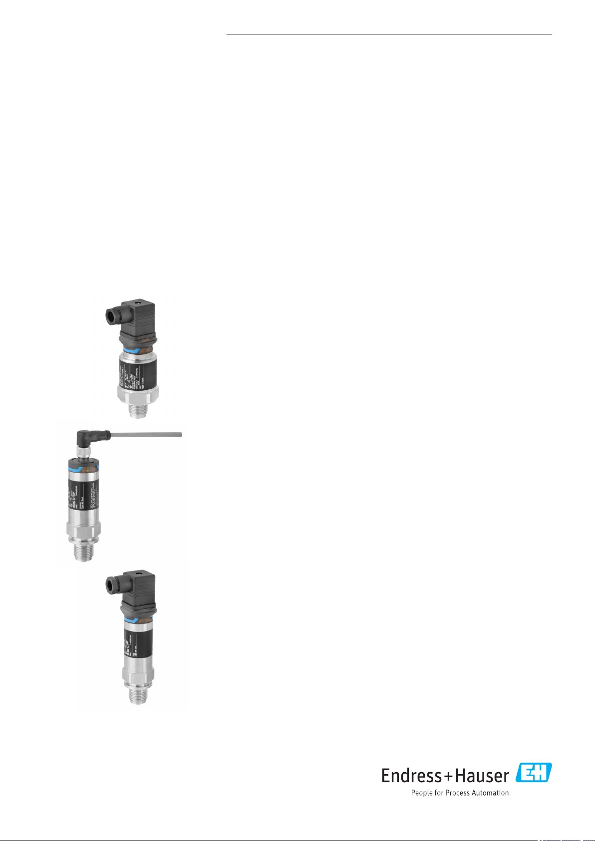
Cerabar PMC11, PMC21,
PMP11, PMP21
Process pressure measurement
Pressure transducer with ceramic and metal
sensors
Application
The Cerabar is a pressure transducer for the measurement of absolute and gauge
pressure in gases, vapors, liquids and dust. The Cerabar can be used internationally
thanks to a wide range of approvals and process connections.
Your benefits
• High reproducibility and long-term stability
• Reference accuracy: up to 0.3%
• Customized measuring ranges
– Turn down up to 5:1
– Sensor for measuring ranges up to 400 bar (6 000 psi)
• Housing and process isolating diaphragm made of 316L
Page 2

Table of contents
Cerabar PMC11, PMC21, PMP11, PMP21
Document information ....................... 4
Document function ............................ 4
Symbols used ................................ 4
Documentation ............................... 5
Terms and abbreviations ........................ 6
Turn down calculation .......................... 7
Function and system design ................... 8
Measuring principle - process pressure measurement ..... 8
Measuring system ............................. 8
Device features ............................... 9
Product design .............................. 11
System integration ........................... 12
Input .................................... 13
Measured variable ............................ 13
Measuring range ............................ 13
Output .................................. 16
Output signal ............................... 16
Signal range 4 to 20 mA ........................ 16
Load (for 4 to 20 mA devices ) .................... 16
Load resistance (for 0 to 10 V devices) .............. 16
Signal on alarm 4 to 20 mA ...................... 16
Dead time, time constant ....................... 16
Dynamic behavior ............................ 17
Power supply ............................. 18
Terminal assignment .......................... 18
Supply voltage .............................. 18
Current consumption and alarm signal .............. 18
Power supply fault ............................ 19
Electrical connection .......................... 19
Cable specification ............................ 19
Residual ripple .............................. 19
Influence of power supply ....................... 19
Overvoltage protection ........................ 19
Performance characteristics of ceramic process
isolating diaphragm ........................ 20
Reference operating conditions ................... 20
Measuring uncertainty for small absolute pressure
measuring ranges ............................ 20
Influence of the installation position ................ 20
Resolution ................................. 20
Reference accuracy ........................... 20
Thermal change of the zero output and the output span ... 20
Long-term stability ........................... 21
Switch-on time .............................. 21
Performance characteristics of metal process
isolating diaphragm ........................ 22
Reference operating conditions ................... 22
Measuring uncertainty for small absolute pressure
measuring ranges ............................ 22
Influence of the installation position ................ 22
Resolution ................................. 22
Reference accuracy ........................... 22
Thermal change of the zero output and the output span ... 22
Long-term stability ........................... 22
Switch-on time .............................. 22
Installation ............................... 23
Installation conditions ......................... 23
Influence of the installation position ................ 23
Mounting location ............................ 23
Mounting instructions for oxygen applications ......... 24
Environment .............................. 26
Ambient temperature range ..................... 26
Storage temperature range ...................... 26
Climate class ............................... 26
Degree of protection .......................... 26
Vibration resistance ........................... 26
Electromagnetic compatibility .................... 26
Process .................................. 27
Process temperature range for devices with ceramic
process isolating diaphragm ..................... 27
Process temperature range for devices with metallic
process isolating diaphragm ..................... 27
Pressure specifications ......................... 28
Mechanical construction .................... 29
Design, dimensions ........................... 29
Electrical connection .......................... 29
Housing ................................... 30
Process connections with internal, ceramic process
isolating diaphragm ........................... 32
Process connections with internal, ceramic process
isolating diaphragm ........................... 33
Process connections with internal, ceramic process
isolating diaphragm ........................... 34
Process connections with internal, ceramic process
isolating diaphragm ........................... 34
Process connections with internal, metal process isolating
diaphragm ................................. 35
Process connections with internal, metal process isolating
diaphragm ................................. 36
Process connections with internal, metal process isolating
diaphragm ................................. 37
Process connections with internal, metal process isolating
diaphragm ................................. 37
Process connections with flush-mounted, metal process
isolating diaphragm ........................... 38
Materials in contact with process .................. 39
Materials not in contact with process ............... 40
Cleaning .................................. 41
Operability ............................... 42
Plug-on display PHX20 (optional) .................. 42
Certificates and approvals ................... 43
CE mark ................................... 43
2 Endress+Hauser
Page 3

Cerabar PMC11, PMC21, PMP11, PMP21
RoHS ..................................... 43
RCM-Tick marking ............................ 43
EAC conformity .............................. 43
Approval .................................. 43
Safety Instructions (XA) ........................ 43
Marine approval (pending) ...................... 44
Pressure Equipment Directive 2014/68/EU (PED) ....... 44
Other standards and guidelines ................... 44
CRN approval ............................... 45
Calibration unit .............................. 45
Calibration ................................. 45
Inspection certificates .......................... 45
Ordering information ....................... 46
Scope of delivery ............................. 46
Accessories ............................... 47
Weld-in adapter ............................. 47
Plug-on display PHX20 ......................... 47
M12 plug connectors .......................... 47
Documentation ............................ 48
Field of Activities ............................ 48
Technical Information ......................... 48
Operating Instructions ......................... 48
Brief Operating Instructions ..................... 48
Safety Instructions (XA) ........................ 48
Endress+Hauser 3
Page 4
Document information
DANGER
WARNING
CAUTION
NOTICE
A
,…,
1.
2.
3.
Cerabar PMC11, PMC21, PMP11, PMP21
Document function
The document contains all the technical data on the device and provides an overview of the
accessories and other products that can be ordered for the device.
Symbols used Safety symbols
Symbol Meaning
Electrical symbols
Symbol Meaning Symbol Meaning
DANGER!
This symbol alerts you to a dangerous situation. Failure to avoid this situation will result in
serious or fatal injury.
WARNING!
This symbol alerts you to a dangerous situation. Failure to avoid this situation can result in
serious or fatal injury.
CAUTION!
This symbol alerts you to a dangerous situation. Failure to avoid this situation can result in
minor or medium injury.
NOTICE!
This symbol contains information on procedures and other facts which do not result in
personal injury.
Protective ground connection
A terminal which must be connected
to ground prior to establishing any
other connections.
Ground connection
A grounded terminal which, as far as
the operator is concerned, is
grounded via a grounding system.
Symbols for certain types of information
Symbol Meaning
Permitted
Procedures, processes or actions that are permitted.
Forbidden
Procedures, processes or actions that are forbidden.
Tip
Indicates additional information.
Reference to documentation
Reference to page
Reference to graphic
Visual inspection
Symbols in graphics
Symbol Meaning
1, 2, 3 ... Item numbers
Series of steps
A, B, C, ... Views
4 Endress+Hauser
Page 5
Cerabar PMC11, PMC21, PMP11, PMP21
Documentation
The document types listed are available:
In the Download Area of the Endress+Hauser Internet site: www.endress.com → Download
Brief Operating Instructions (KA): getting the 1st measured value quickly
These instructions contain all the essential information from incoming acceptance to initial
commissioning.
Operating Instructions (BA): your comprehensive reference
These Operating Instructions contain all the information that is required in various phases of the life
cycle of the device: from product identification, incoming acceptance and storage, to mounting,
connection, operation and commissioning through to troubleshooting, maintenance and disposal.
Safety Instructions (XA)
Depending on the approval, the following Safety Instructions (XA) are supplied with the device. They
are an integral part of the Operating Instructions.
Device Directive Documentation Option
PMP21 ATEX II 1/2G Ex ia IIC T4 Ga/Gb XA01271P BA
PMC21 ATEX II 2G Ex ia IIC T4 Gb XA01271P BB
PMC21
PMP21
PMC21
PMP21
PMC21
PMP21
PMC21
PMP21
PMC21
PMP21
PMC21
PMP21
PMC21
PMP21
ATEX II 3G Ex ec IIC T4 Gc XA01533P BC
FM IS Cl. I, Div.1 Gr. A-D T4 XA01321P FA
CSA C/US IS Cl. I Div. 1 Gr. A-D XA01322P CB
EAC Ex ia IIC T4 Ga/Gb XA01540P GA
IEC Ex ia IIC T4 Ga/Gb XA01271P IA
NEPSI Ex ia IIC T4 XA01363P NA
TIIS Ex ia IIC T4 In preparation TA
1)
1) Product Configurator order code for "Approval"
The nameplate indicates the Safety Instructions (XA) that are relevant to the device.
Endress+Hauser 5
Page 6
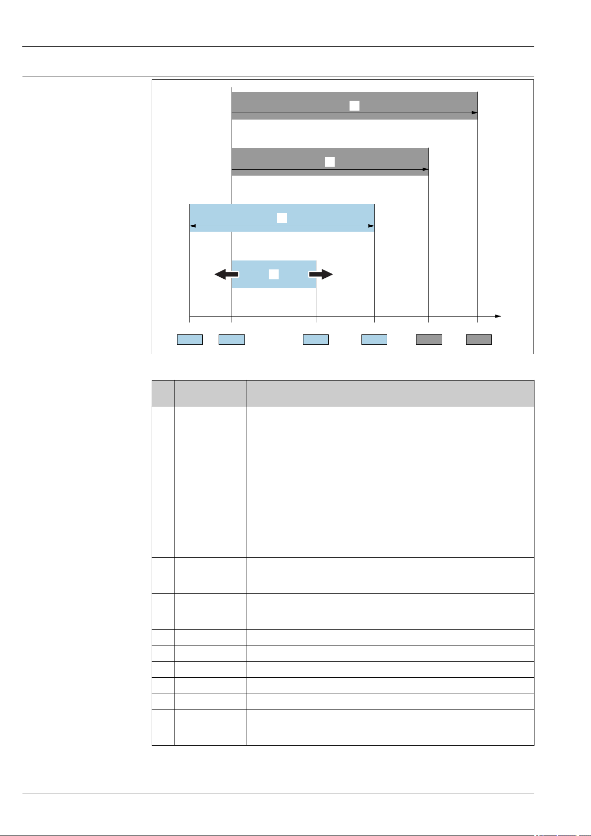
Terms and abbreviations
URL OPLMWP
LRL
0
p
LRV
URV
1
2
3
4
Cerabar PMC11, PMC21, PMP11, PMP21
A0029505
Item Term/
abbreviation
1 OPL The OPL (over pressure limit = sensor overload limit) for the measuring device
2 MWP The MWP (maximum working pressure) for the sensors depends on the lowest-
3 Maximum sensor
measuring range
4 Calibrated/
adjusted span
p - Pressure
- LRL Lower range limit
- URL Upper range limit
- LRV Lower range value
- URV Upper range value
- TD (turn down) Turn down
Explanation
depends on the lowest-rated element, with regard to pressure, of the selected
components, i.e. the process connection has to be taken into consideration in
addition to the measuring cell. Also observe pressure-temperature dependency. For
the relevant standards and additional notes, see the "Pressure specifications" section
→ 28 .
The OPL may only be applied for a limited period of time.
rated element, with regard to pressure, of the selected components, i.e. the process
connection has to be taken into consideration in addition to the measuring cell.
Also observe pressure-temperature dependency. For the relevant standards and
additional notes, see the "Pressure specifications" section → 28 .
The MWP may be applied at the device for an unlimited period.
The MWP can also be found on the nameplate.
Span between LRL and URL
This sensor measuring range is equivalent to the maximum calibratable/adjustable
span.
Span between LRV and URV
Factory setting: 0 to URL
Other calibrated spans can be ordered as customized spans.
The turn down is preset at the factory and cannot be changed.
Example - see the following section.
6 Endress+Hauser
Page 7

Cerabar PMC11, PMC21, PMP11, PMP21
LRV
URLURV
LRL
1 = 2
3
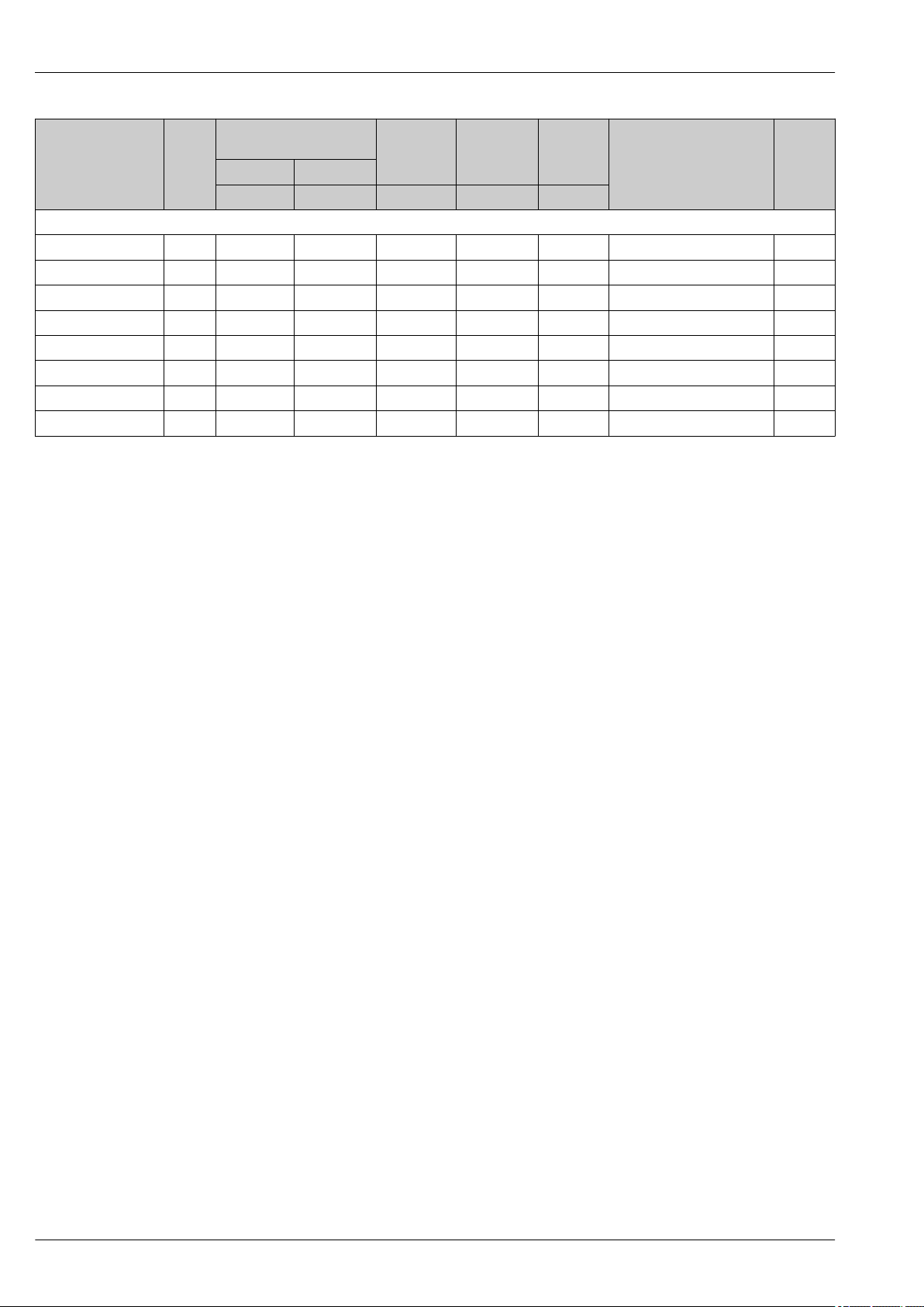
Turn down calculation
1 Calibrated/adjusted span
2 Zero point-based span
3 URL sensor
Example
• Sensor:10 bar (150 psi)
• Upper range value (URL) = 10 bar (150 psi)
Turn down (TD):
A0029545
• Calibrated/adjusted span: 0 to 5 bar (0 to 75 psi)
• Lower range value (LRV) = 0 bar (0 psi)
• Upper range value (URV) = 5 bar (75 psi)
TD =
URL
|URV - LRV|
10 bar (150 psi)
TD =
|5 bar (75 psi) - 0 bar (0 psi)|
In this example, the TD is 2:1.
This span is based on the zero point.
= 2
Endress+Hauser 7
Page 8
Function and system design
1
2
3
4
p
p
1
3
4
2
Cerabar PMC11, PMC21, PMP11, PMP21
Measuring principle process pressure
measurement
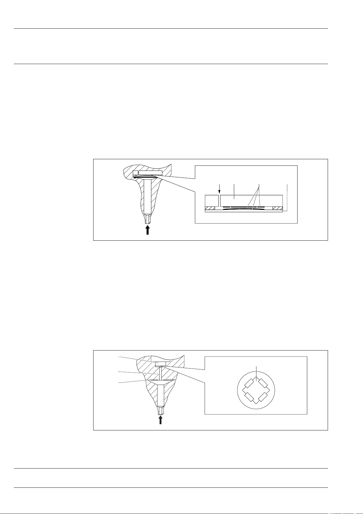
Devices with ceramic process isolating diaphragm (Ceraphire®)
The ceramic sensor is an oil-free sensor, i.e. the process pressure acts directly on the robust ceramic
process isolating diaphragm and causes it to deflect. A pressure-dependent change in capacitance is
measured at the electrodes of the ceramic substrate and the process isolating diaphragm. The
measuring range is determined by the thickness of the ceramic process isolating diaphragm.
Advantages:
• Guaranteed overload resistance up to 40 times the nominal pressure
• The ultrapure 99.9% ceramic (Ceraphire®, see also "www.endress.com/ceraphire") ensures:
– Extremely high chemical durability
– High mechanical durability
• Can be used in absolute vacuum
• Small measuring ranges
A0020465
1 Air pressure (gauge pressure sensors)
2 Ceramic substrate
3 Electrodes
4 Ceramic process isolating diaphragm
Devices with metallic process isolating diaphragm
The process pressure deflects the metal process isolating diaphragm of the sensor and a fill fluid
transfers the pressure to a Wheatstone bridge (semiconductor technology). The pressure-dependent
change in the bridge output voltage is measured and evaluated.
Advantages:
• Can be used for high process pressures
• Fully welded sensor
• Slim, flush-mounted process connections available
A0016448
1 Silicon measuring element, substrate
2 Wheatstone bridge
3 Channel with fill fluid
4 Metal process isolating diaphragm
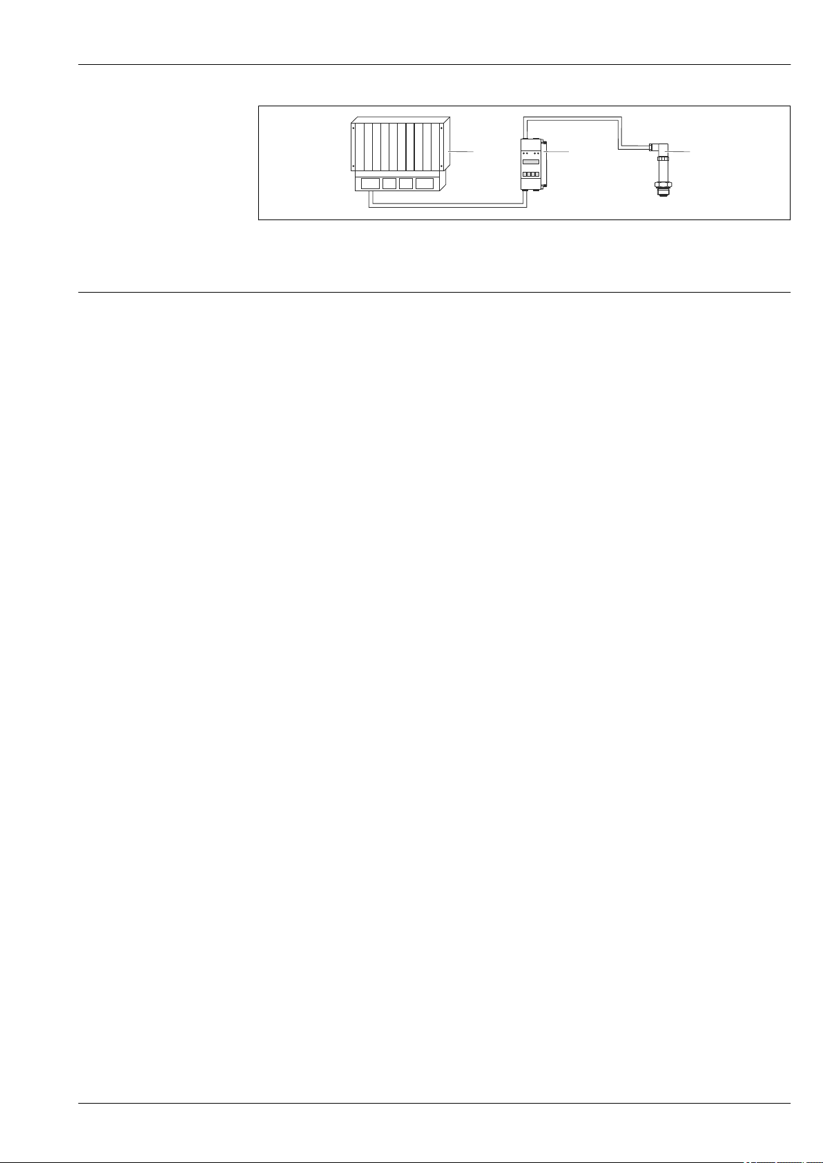
Measuring system
A complete measuring system comprises:
8 Endress+Hauser
Page 9
Cerabar PMC11, PMC21, PMP11, PMP21
1
2
3
1 PLC (programmable logic control)
2 e.g. RN221N / RMA42 (if required)
3 Pressure transducer
Device features Field of application
• PMC11: Gauge pressure
• PMP11: Gauge pressure
• PMC21: Gauge and absolute pressure
• PMP21: Gauge and absolute pressure
Process connections
PMC11:
• Thread ISO 228
• Thread ASME
• DIN 13
PMP11:
• Thread ISO 228, also flush-mount
• Thread ASME
• DIN 13
PMC21:
• Thread ISO 228
• Thread DIN 13
• Thread ASME
• Thread JIS
PMP21:
• Thread ISO 228, also flush-mount
• Thread DIN 13
• Thread ASME
• Thread JIS
A0021926
Measuring ranges
• PMC11: from –400 to +400 mbar (–6 to +6 psi) to –1 to +40 bar (–15 to +600 psi).
• PMP11: from –400 to +400 mbar (–6 to +6 psi) to –1 to +40 bar (–15 to +600 psi).
• PMC21: from –100 to +100 mbar (–1.5 to +1.5 psi) to –1 to +40 bar (–15 to +600 psi).
• PMP21: from –400 to +400 mbar (–6 to +6 psi) to –1 to +400 bar (–15 to +6 000 psi).
OPL (depends on the measuring range)
• PMC11: max. 0 to +60 bar (0 to +900 psi)
• PMP11: max. 0 to +160 bar (0 to +2 400 psi)
• PMC21: max. 0 to +60 bar (0 to +900 psi)
• PMP21: max. 0 to +600 bar (0 to +9 000 psi)
MWP
• PMC11: max. 0 to +60 bar (0 to +900 psi)
• PMP11: max. 0 to +160 bar (0 to +2 400 psi)
• PMP21: max. 0 to +600 bar (0 to +9 000 psi)
• PMC21: max. 0 to +60 bar (0 to +900 psi)
Process temperature range (temperature at process connection)
• PMC11: –25 to +85 °C (–13 to +185 °F)
• PMP11: –25 to +85 °C (–13 to +185 °F)
• PMC21: –25 to +100 °C (–13 to +212 °F)
• PMP21: –40 to +100 °C (–40 to +212 °F)
Endress+Hauser 9
Page 10

Cerabar PMC11, PMC21, PMP11, PMP21
Ambient temperature range
PMC11: –40 to +70 °C (–40 to +158 °F)
PMP11: –40 to +70 °C (–40 to +158 °F)
PMC21:
• –40 to +85 °C (–40 to +185 °F)
• Devices for hazardous areas: –40 to +70 °C (–40 to +158 °F)
PMP21:
–40 to +85 °C (–40 to +185 °F)
Reference accuracy
• PMC11: up to 0.5 %, TD 5:1, for details, see "Reference accuracy" section.
• PMP11: up to 0.5 %, TD 5:1, for details, see "Reference accuracy" section.
• PMC21: up to 0.3 %, TD 5:1, for details, see "Reference accuracy" section.
• PMP21: up to 0.3 %, TD 5:1, for details, see "Reference accuracy" section.
Supply voltage
PMC11:
• 4 to 20 mA output: 10 to 30V DC
• 0 to 10 V output: 12 to 30V DC
PMP11:
• 4 to 20 mA output: 10 to 30V DC
• 0 to 10 V output: 12 to 30V DC
PMC21:
10 to 30 V DC
PMP21:
10 to 30 V DC
Output
PMC11:
• 4 to 20 mA
• 0 to 10 V
PMP11:
• 4 to 20 mA
• 0 to 10 V
PMC21:
4 to 20 mA
PMP21:
4 to 20 mA
Material
PMC11:
• Housing made from 316L (1.4404)
• Process connections made from 316L
• Process isolating diaphragm made from Al2O3 aluminum oxide ceramic, (Ceraphire®), ultrapure
99.9 %
PMP11:
• Housing made from 316L (1.4404)
• Process connections made from 316L (1.4404)
• Process isolating diaphragm made from 316L (1.4435)
PMC21:
• Housing made from 316L (1.4404)
• Process connections made from 316L
• Process isolating diaphragm made from Al2O3 aluminum-oxide ceramic, (Ceraphire®), ultrapure
99.9 %
PMP21:
• Housing made from 316L (1.4404)
• Process connections made from 316L (1.4404)
• Process isolating diaphragm made from 316L (1.4435)
10 Endress+Hauser
Page 11
Cerabar PMC11, PMC21, PMP11, PMP21
A
B
C - 1
C - 2
D
E
D
E
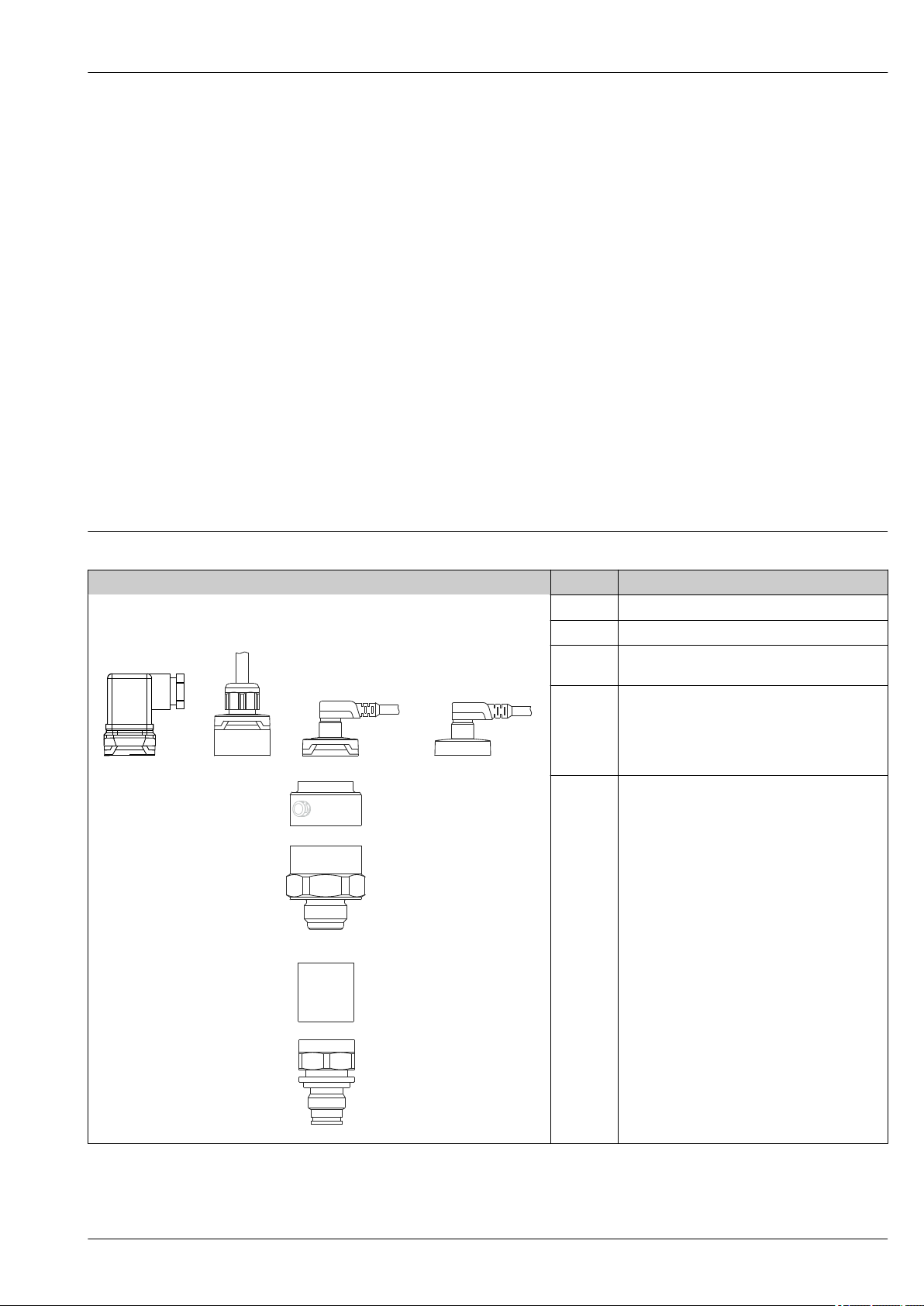
Options
PMC11:
• Certificate of calibration
• Cleaned from oil+grease
PMP11:
• Certificate of calibration
• Cleaned from oil+grease
PMC21:
• Ex approvals
• Marine certificate
• Min. alarm current setting
• 3.1 Material certificates
• Certificate of calibration
• Cleaned from oil+grease
• Cleaned for O2 service
PMP21:
• Ex approvals
• Marine certificate
• Min. alarm current setting
• 3.1 Material certificates
• Certificate of calibration
• Cleaned from oil+grease
A0027232
A Valve plug
B Cable
C- 1 M12 plug
Housing cap made of plastic
C- 2 M12 plug
For Ex ec and IP69: metal housing cap
A0021987
A0027289
A0027226
D
E
Housing
Process connection (sample illustration)
Product design
Overview Position Description
A0027231
A0027215
Endress+Hauser 11
Page 12

Cerabar PMC11, PMC21, PMP11, PMP21
System integration
The device can be given a tag name (max. 32 alphanumeric characters).
Designation Option
Measuring point (TAG), see additional specifications Z1
1) Product Configurator order code for "Marking"
1)
12 Endress+Hauser
Page 13
Cerabar PMC11, PMC21, PMP11, PMP21
Input
Measured variable Measured process variable
• PMC11: Gauge pressure
• PMP11: Gauge pressure
• PMC21: Gauge pressure or absolute pressure
• PMP21: Gauge pressure or absolute pressure
Calculated process variable
Pressure
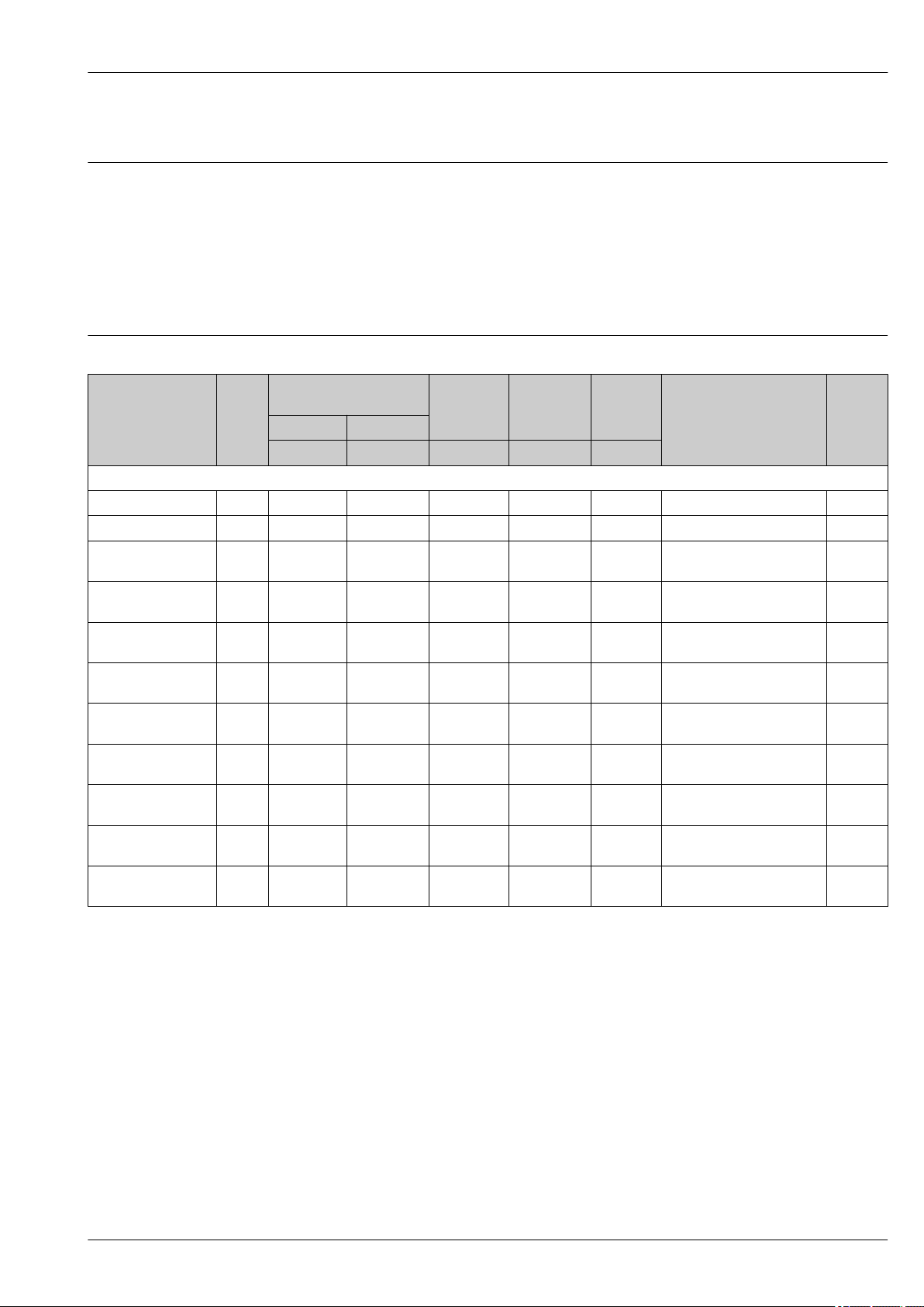
Measuring range Ceramic process isolating diaphragm
Sensor Device Maximum
Sensor measuring range
lower (LRL) upper (URL)
[bar (psi)] [bar (psi)] [bar (psi)] [bar (psi)] [bar (psi)]
Devices for gauge pressure measurement
100 mbar (1.5 psi)
250 mbar (4 psi)
400 mbar (6 psi)
4)
PMC21 –0.1 (–1.5) +0.1 (+1.5) 0.02 (0.3) 2.7 (40.5) 4 (60) 0 to 100 mbar (0 to 1.5 psi) 1C
5)
PMC21 –0.25 (–4) +0.25 (+4) 0.05 (1) 3.3 (49.5) 5 (75) 0 to 250 mbar (0 to 4 psi) 1E
6)
PMC11
–0.4 (–6) +0.4 (+6) 0.08 (1.2) 5.3 (79.5) 8 (120) 0 to 400 mbar (0 to 6 psi) 1F
PMC21
1 bar (15 psi)
6)
PMC11
–1 (–15) +1 (+15) 0.2 (3) 6.7 (100.5) 10 (150) 0 to 1 bar (0 to 15 psi) 1H
PMC21
2 bar (30 psi)
6)
PMC11
–1 (–15) +2 (+30) 0.4 (6) 12 (180) 18 (270) 0 to 2 bar (0 to 30 psi) 1K
PMC21
4 bar (60 psi)
6)
PMC11
–1 (–15) +4 (+60) 0.8 (12) 16.7 (250.5) 25 (375) 0 to 4 bar (0 to 60 psi) 1M
PMC21
6 bar (90 psi)
6)
PMC11
–1 (–15) +6 (+90) 2.4 (36) 26.7 (400.5) 40 (600) 0 to 6 bar (0 to 90 psi) 1N
PMC21
10 bar (150 psi)
6)
PMC11
–1 (–15) +10 (+150) 2 (30) 26.7 (400.5) 40 (600) 0 to 10 bar (0 to 150 psi) 1P
PMC21
16 bar (240 psi)
6)
PMC11
–1 (–15) +16 (+240) 6.4 (96) 40 (600) 60 (900) 0 to 16 bar (0 to 240 psi) 1Q
PMC21
25 bar (375 psi)
6)
PMC11
–1 (–15) +25 (+375) 10 (150) 40 (600) 60 (900) 0 to 25 bar (0 to 375 psi) 1R
PMC21
40 bar (600 psi)
6)
PMC11
–1 (–15) +40 (+600) 8 (120) 40 (600) 60 (900) 0 to 40 bar (0 to 600 psi) 1S
PMC21
Lowest
calibratable
1)
span
MWP OPL Factory settings
2)
Option
3)
Endress+Hauser 13
Page 14
Cerabar PMC11, PMC21, PMP11, PMP21
Sensor Device Maximum
Sensor measuring range
lower (LRL) upper (URL)
Lowest
calibratable
1)
span
MWP OPL Factory settings
2)
Option
[bar (psi)] [bar (psi)] [bar (psi)] [bar (psi)] [bar (psi)]
Devices for absolute pressure measurement
100 mbar (1.5 psi)
250 mbar (4 psi)
400 mbar (6 psi)
1 bar (15 psi)
2 bar (30 psi)
4 bar (60 psi)
10 bar (150 psi)
40 bar (600 psi)
6)
PMC21 0 +0.1 (+1.5) 0.1 (1.5) 2.7 (40.5) 4 (60) 0 to 100 mbar (0 to 1.5 psi) 2C
6)
PMC21 0 +0.25 (+4) 0.25 (4) 3.3 (49.5) 5 (75) 0 to 250 mbar (0 to 4 psi) 2E
6)
PMC21 0 +0.4 (+6) 0.4 (6) 5.3 (79.5) 8 (120) 0 to 400 mbar (0 to 6 psi) 2F
6)
6)
6)
PMC21 0 +1 (+15) 0.4 (6) 6.7 (100.5) 10 (150) 0 to 1 bar (0 to 15 psi) 2H
PMC21 0 +2 (+30) 0.4 (6) 12 (180) 18 (270) 0 to 2 bar (0 to 30 psi) 2K
PMC21 0 +4 (+60) 0.8 (12) 16.7 (250.5) 25 (375) 0 to 4 bar (0 to 60 psi) 2M
6)
PMC21 0 +10 (+150) 2 (30) 26.7 (400.5) 40 (600) 0 to 10 bar (0 to 150 psi) 2P
6)
PMC21 0 +40 (+600) 8 (120) 40 (600) 60 (900) 0 to 40 bar (0 to 600 psi) 2S
1) Highest turn down that can be set at the factory: 5:1. The turn down is preset and cannot be changed.
2) Other measuring ranges (e.g. –1 to +5 bar (–15 to 75 psi)) can be ordered with customer-specific settings (see the Product Configurator, order
code for "Calibration; Unit" option "J"). It is possible to invert the output signal (LRV = 20 mA; URV = 4 mA). Prerequisite: URV < LRV
3) Product Configurator, order code for "Sensor range"
4) Vacuum resistance: 0.7 bar (10.5 psi) abs
5) Vacuum resistance: 0.5 bar (7.5 psi) abs
6) Vacuum resistance: 0 bar (0 psi) abs
3)
Maximum turn down which can be ordered for absolute pressure and gauge pressure sensors
Devices for gauge pressure measurement
• 6 bar (90 psi), 16 bar (240 psi), 25 bar (375 psi): TD 1:1 to TD 2.5:1
• All other measuring ranges: TD 1:1 to TD 5:1
Devices for absolute pressure measurement
• 100 mbar (1.5 psi), 250 mbar (4 psi), 400 mbar (6 psi): TD 1:1
• 1 bar (15 psi): TD 1:1 to TD 2.5:1
• All other measuring ranges: TD 1:1 to TD 5:1
14 Endress+Hauser
Page 15
Cerabar PMC11, PMC21, PMP11, PMP21
Metal process isolating diaphragm
Sensor Device Maximum
Sensor measuring range
lower (LRL) upper (URL)
[bar (psi)] [bar (psi)] [bar (psi)] [bar (psi)] [bar (psi)]
Devices for gauge pressure measurement
400 mbar (6 psi)
4)
PMP11
–0.4 (–6) +0.4 (+6) 0.4 (6) 1 (15) 1.6 (24) 0 to 400 mbar (0 to 6 psi) 1F
PMP21
1 bar (15 psi)
4)
PMP11
–1 (–15) +1 (+15) 0.4 (6) 2.7 (40.5) 4 (60) 0 to 1 bar (0 to 15 psi) 1H
PMP21
2 bar (30 psi)
4)
PMP11
–1 (–15) +2 (+30) 0.4 (6) 6.7 (100.5) 10 (150) 0 to 2 bar (0 to 30 psi) 1K
PMP21
4 bar (60 psi)
4)
PMP11
–1 (–15) +4 (+60) 0.8 (12) 10.7 (160.5) 16 (240) 0 to 4 bar (0 to 60 psi) 1M
PMP21
6 bar (90 psi)
4)
PMP11
–1 (–15) +6 (+90) 2.4 (36) 16 (240) 24 (360) 0 to 6 bar (0 to 90 psi) 1N
PMP21
10 bar (150 psi)
4)
PMP11
–1 (–15) +10 (+150) 2 (30) 25 (375) 40 (600) 0 to 10 bar (0 to 150 psi) 1P
PMP21
16 bar (240 psi)
4)
PMP11
–1 (–15) +16 (+240) 5 (75) 25 (375) 64 (960) 0 to 16 bar (0 to 240 psi) 1Q
PMP21
25 bar (375 psi)
4)
PMP11
–1 (–15) +25 (+375) 5 (75) 25 (375) 100 (1500) 0 to 25 bar (0 to 375 psi) 1R
PMP21
40 bar (600 psi)
4)
PMP11
–1 (–15) +40 (+600) 8 (120) 100 (1500) 160 (2400) 0 to 40 bar (0 to 600 psi) 1S
PMP21
100 bar (1 500 psi)
400 bar (6 000 psi)
4)
PMP21 –1 (–15) +100 (+1500) 20 (300) 100 (1500) 160 (2400) 0 to 100 bar (0 to 1 500 psi) 1U
4)
PMP21 –1 (–15) +400 (+6000) 80 (1200) 400 (6000) 600 (9000) 0 to 400 bar (0 to 6 000 psi) 1W
Devices for absolute pressure measurement
400 mbar (6 psi)
1 bar (15 psi)
2 bar (30 psi)
4 bar (60 psi)
10 bar (150 psi)
40 bar (600 psi)
100 bar (1 500 psi)
400 bar (6 000 psi)
4)
PMP21 0 (0) 0.4 (+6) 0.4 (6) 1 (15) 1.6 (24) 0 to 400 mbar (0 to 6 psi) 2F
4)
4)
4)
PMP21 0 (0) 1 (+15) 0.4 (6) 2.7 (40.5) 4 (60) 0 to 1 bar (0 to 15 psi) 2H
PMP21 0 (0) 2 (+30) 0.4 (6) 6.7 (100.5) 10 (150) 0 to 2 bar (0 to 30 psi) 2K
PMP21 0 (0) 4 (+60) 0.8 (12) 10.7 (160.5) 16 (240) 0 to 4 bar (0 to 60 psi) 2M
4)
PMP21 0 (0) 10 (+150) 2 (30) 25 (375) 40 (600) 0 to 10 bar (0 to 150 psi) 2P
4)
PMP21 0 (0) +40 (+600) 8 (120) 100 (1500) 160 (2400) 0 to 40 bar (0 to 600 psi) 2S
4)
PMP21 0 (0) +100 (+1500) 20 (300) 100 (1500) 160 (2400) 0 to 100 bar (0 to 1 500 psi) 2U
4)
PMP21 0 (0) +400 (+6000) 80 (1200) 400 (6000) 600 (9000) 0 to 400 bar (0 to 6 000 psi) 2W
Lowest
calibratable
1)
span
MWP OPL Factory settings
2)
Option
3)
1) Highest turn down that can be set at the factory: 5:1. The turn down is preset and cannot be changed.
2) Other measuring ranges (e.g. –1 to +5 bar (–15 to 75 psi)) can be ordered with customer-specific settings (see the Product Configurator, order
code for "Calibration; Unit" option "J"). It is possible to invert the output signal (LRV = 20 mA; URV = 4 mA). Prerequisite: URV < LRV
3) Product Configurator, order code for "Sensor range"
4) Vacuum resistance: 0.01 bar (0.145 psi) abs
Maximum turn down which can be ordered for absolute pressure and gauge pressure sensors
Device Range 400 mbar (6 psi) 1 bar (15 psi)
6 bar (90 psi)
16 bar (240 psi)
PMP11 0.5% TD 1:1 TD 1:1 to TD 2.5:1 TD 1:1 to TD 5:1
PMP21 0.3% TD 1:1 TD 1:1 to TD 2.5:1 TD 1:1 to TD 5:1
2 bar (30 psi)
4 bar (60 psi)
10 bar (150 psi)
25 to 400 bar (375 to 6 000 psi)
Endress+Hauser 15
Page 16
Output
[ ]W
30
20
10
1068
614
U
[V]
1
R
L
max
B
2
R
L
max
£
-U 6.5V
22mA
B
I
63 %
100 %
t
t1t
2
90 %
t
3
Cerabar PMC11, PMC21, PMP11, PMP21
Output signal
Signal range 4 to 20 mA
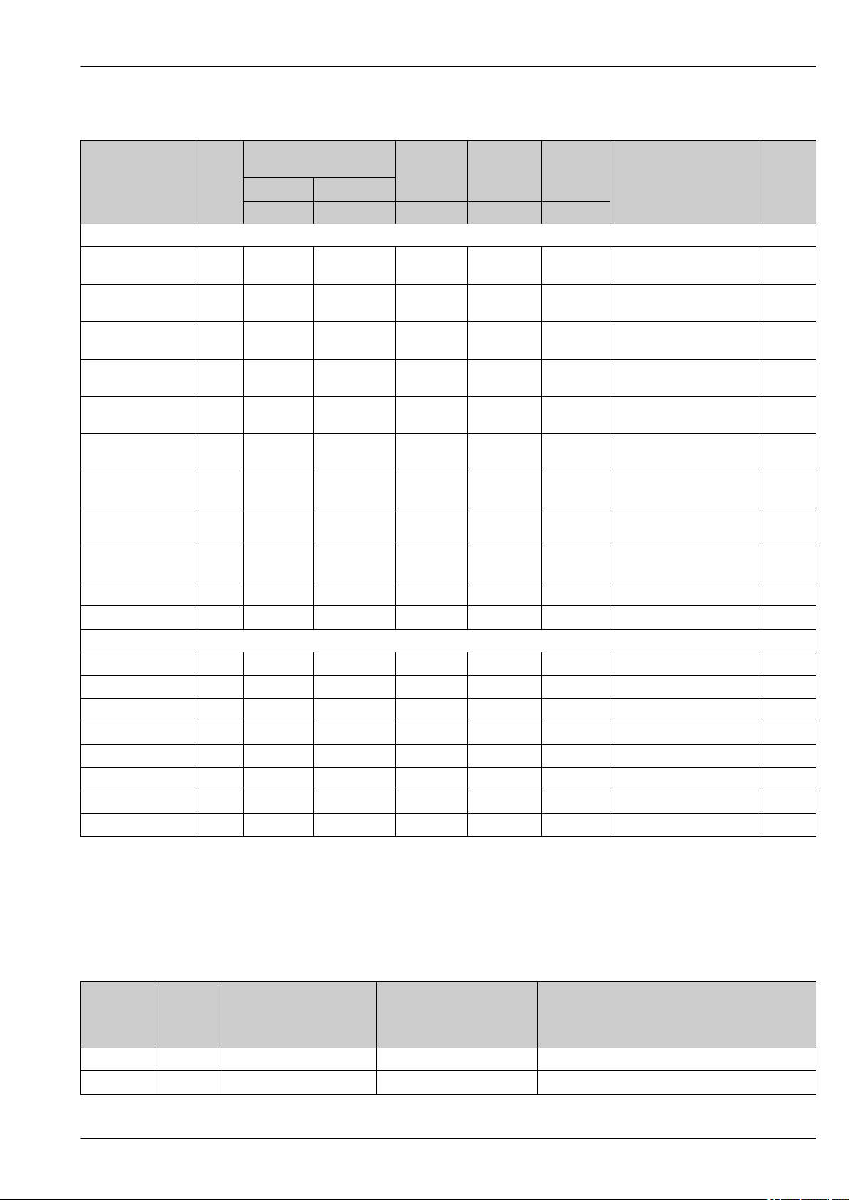
Load (for 4 to 20 mA devices )
Designation Option
4 to 20 mA (2-wire) 1
PMC11: 0 to 10 V output (3-wire)
PMP11: 0 to 10 V output (3-wire)
1) Product Configurator, order code for "Output"
1)
2
3.8 mA to 20.5 mA
In order to guarantee sufficient terminal voltage in two-wire devices, a maximum load resistance R
(including line resistance) must not be exceeded depending on the supply voltage UB of the supply
unit.
A0029452
1 Power supply 10 to 30 V DC
2 R
UBSupply voltage
Maximum load resistance
Lmax
L
Load resistance (for 0 to 10 V devices)
Signal on alarm 4 to 20 mA
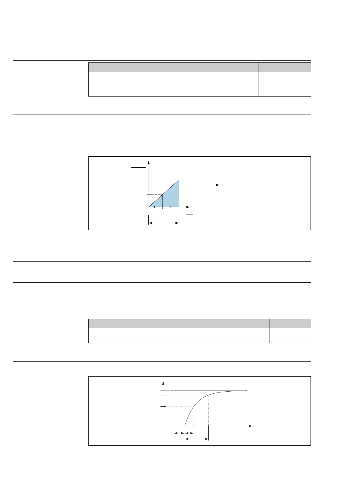
Dead time, time constant
The load resistance must be ≥ 5 [kΩ].
The response of the output to error is regulated in accordance with NAMUR NE43.
Factory setting MAX alarm: >21 mA
alarm current
Device Description Option
PMC21
PMP21
1) Product Configurator order code for "Service"
Adjusted min. alarm current IA
Presentation of the dead time and the time constant:
1)
A0019786
16 Endress+Hauser
Page 17

Cerabar PMC11, PMC21, PMP11, PMP21
Dynamic behavior
Dead time (t1) [ms] Time constant (T63), t2 [ms] Time constant (T90), t3 [ms]
6 ms 10 ms 15 ms
Endress+Hauser 17
Page 18

Cerabar PMC11, PMC21, PMP11, PMP21
L–
L+
2
1
3
0.5A
L–
L+
1
2
3
4
0.5A
L–
L+
1
2
3
(a)
0.5A
L–
L+
2
1
3
0.5A
L–
L+
1
2
3
4
0.5A
Power supply
WARNING
L
Limitation of electrical safety due to incorrect connection!
In accordance with IEC/EN61010 a separate circuit breaker must be provided for the device .
‣
When using the measuring device in hazardous areas, installation must comply with the
‣
corresponding national standards and regulations and the Safety Instructions or Installation or
Control Drawings.
All explosion protection data are given in separate documentation which is available upon
‣
request. The Ex documentation is supplied as standard with all devices approved for use in
explosion hazardous areas.
Protective circuits against reverse polarity, HF influences and overvoltage peaks are integrated.
‣
The device must be operated with a 500 mA fine-wire fuse (slow-blow).
‣
Terminal assignment
4 to 20 mA output
Device M12 plug Valve plug Cable
PMC11
PMP11
PMC21
PMP21
A0023487
A0022823
1 brown = L+
2 blue = L3 green/yellow = ground connection
(a) reference air hose
0 to 10 V output
Device M12 plug Valve plug Cable
PMC11
PMP11
A0017576
-
A0022822
A0023783
Supply voltage
Current consumption and alarm signal
18 Endress+Hauser
Electronic version Device Supply voltage
4 to 20 mA output PMC11
PMP11
PMC21
PMP21
0 to 10 V output PMC11
PMP11
Number of wires Device Normal operation Alarm signal
2 PMC11
PMP11
PMC21
PMP21
3 PMC11
PMP11
1) For MAX alarm (factory setting)
≤ 26 mA > 21 mA
< 12 mA 11 V
10 to 30 V DC
12 to 30 V DC
1)
Page 19

Cerabar PMC11, PMC21, PMP11, PMP21
Power supply fault
• Behavior in the event of overvoltage (>30 V):
The device works continuously up to 34 V DC without damage. If the supply voltage is exceeded,
the specified characteristics are no longer guaranteed.
• Behavior in the event of undervoltage:
If the supply voltage falls below the minimum value, the device switches off in a defined manner
(status same as for no power supply).
Electrical connection Degree of protection
Device Connection Degree of protection Option
PMP21
PMP21
PMP21
PMP21
PMP21
PMP21
PMC11
PMP11
PMC21
PMP21
PMC11
PMP11
PMC21
PMP21
PMC11
PMP11
PMC21
PMP21
Cable5 m (16 ft) IP66/68
Cable10 m (33 ft) IP66/68
Cable25 m (82 ft) IP66/68
M12 plug IP65 NEMA type 4X enclosure L
M12 plug IP65/67 NEMA type 4X enclosure M
Valve plug ISO4400 M16 IP65 NEMA type 4X enclosure U
Valve plug ISO4400 NPT ½ IP65 NEMA type 4X enclosure V
2)
NEMA type 4X/6P enclosure A
2)
NEMA type 4X/6P enclosure B
2)
NEMA type 4X/6P enclosure C
1)
Cable specification
Residual ripple
Influence of power supply
Overvoltage protection
1) Product Configurator order code for "Electrical connection"
2) IP 68 (1.83m H2O for 24 h)
For valve plug: < 1.5 mm2 (16 AWG) and Ø4.5 to 10 mm (0.18 to 0.39 in)
The device operates within the reference accuracy up to ±5 % of the residual ripple of the supply
voltage, within the permitted voltage range.
≤0.005 % of the URL/1 V
The device does not contain any special elements to protect against overvoltage ("wire to ground").
Nevertheless the requirements of the applicable EMC standard EN 61000-4-5 (testing voltage 1kV
EMC wire/ground) are met.
Endress+Hauser 19
Page 20

Cerabar PMC11, PMC21, PMP11, PMP21
Performance characteristics of ceramic process isolating diaphragm
Reference operating conditions
Measuring uncertainty for small absolute pressure measuring ranges
Influence of the installation position
Resolution
Reference accuracy
• As per IEC 60770
• Ambient temperature TA = constant, in the range of:+21 to +33 °C (+70 to +91 °F)
• Humidity φ = constant, in the range of 5 to 80 % rH
• Ambient pressure pA = constant, in the range of:860 to 1 060 mbar (12.47 to 15.37 psi)
• Position of measuring cell = constant, in range: horizontal ±1° (see also "Influence of the
installation position" section → 23)
• Zero based span
• Material of process isolating diaphragm: Al2O3 (aluminum-oxide ceramic, Ceraphire®)
• Supply voltage: 24 V DC ±3 V DC
• Load: 320 Ω (at 4 to 20 mA output)
The smallest extended uncertainty of measurement that can delivered by our standards is:
• in range 1 to 30 mbar (0.0145 to 0.435 psi): 0.4 % of reading
• in range < 1 mbar (0.0145 psi): 1 % of reading.
→ 23
Current output: min. 1.6 μA
The reference accuracy contains the non-linearity [DIN EN 61298-2 3.11] including the pressure
hysteresis [DIN EN 61298-23.13] and non-repeatability [DIN EN 61298-2 3.11] in accordance with
the limit point method as per [DIN EN 60770].
Device % of the calibrated span to the maximum turn down
Reference accuracy Non-linearity
2)
PMC11
PMC21 ±0.3 ±0.1 ±0.1
±0.5 ±0.1 ±0.1
1)
Non-repeatability
Thermal change of the zero output and the output span
1) The non-linearity for the 40 bar (600 psi) sensor can be up to ± 0.15% of the calibrated span up to the
maximum turn down.
2) For devices with 0 to 10 V output, a non-linearity of up to max. 0.3 V can occur for signal values below
0.03 V.
Overview of the turn down ranges → 14
Measuring ranges Turn down Device % of URL
100 mbar (1.5 psi)to
40 bar (600 psi)
1) For the 100 mbar (1.5 psi) and 250 mbar (4 psi) measuring ranges, the following applies: In the event of
heat effects on the initial reference conditions, an additional deviation of max. 0.3 mbar (4.5 psi) from the
zero point or the output span is possible.
Measuring cell –20 to +85 °C (–4 to +185 °F) –40 to –20 °C (–40 to –4 °F)
% of URL for TD 1:1
<1 bar (15 psi) <1 <1.2
≥ 1 bar (15 psi) <0.8 <1
1:1 to TD 5:1 PMC11 ±0.5
PMC21 ±0.3
+85 to +100 °C (+185 to +212 °F)
1)
20 Endress+Hauser
Page 21

Cerabar PMC11, PMC21, PMP11, PMP21
Long-term stability
Switch-on time
1 year 5 years 8 years
% of URL
±0.2 ±0.4 ±0.45
≤2 s (For small measuring ranges, pay attention to the thermal compensation effects.)
Endress+Hauser 21
Page 22

Cerabar PMC11, PMC21, PMP11, PMP21
Performance characteristics of metal process isolating diaphragm
Reference operating conditions
Measuring uncertainty for small absolute pressure measuring ranges
Influence of the installation position
Resolution
Reference accuracy
• As per IEC 60770
• Ambient temperature TA = constant, in the range of:+21 to +33 °C (+70 to +91 °F)
• Humidity φ = constant, in the range of 5 to 80 % rH
• Ambient pressure pA = constant, in the range of:860 to 1 060 mbar (12.47 to 15.37 psi)
• Position of measuring cell = constant, in range: horizontal ±1° (see also "Influence of the
installation position" section → 23)
• Zero based span
• Process isolating diaphragm material: AISI 316L (1.4435)
• Filling oil: synthetic oil polyalphaolefin FDA 21 CFR 178.3620, NSF H1
• Supply voltage: 24 V DC ±3 V DC
• Load: 320 Ω (at 4 to 20 mA output)
The smallest extended uncertainty of measurement that can delivered by our standards is:
• in the range 1 to 30 mbar (0.0145 to 0.435 psi): 0.4 % of reading
• in the range < 1 mbar (0.0145 psi): 1 % of reading.
→ 23
Current output: min. 1.6 μA
The reference accuracy contains the non-linearity [DIN EN 61298-2 3.11] including the pressure
hysteresis [DIN EN 61298-23.13] and non-repeatability [DIN EN 61298-2 3.11] in accordance with
the limit point method as per [DIN EN 60770].
Device % of the calibrated span to the maximum turn down
Reference accuracy Non-linearity Non-repeatability
1)
PMP11
PMP21 ±0.3 ±0.1 ±0.1
±0.5 ±0.1 ±0.1
Thermal change of the zero output and the output span
Long-term stability
Switch-on time
1) For devices with 0 to 10 V output, a non-linearity of up to max. 0.3 V can occur for signal values below
0.015 V.
Overview of the turn down ranges → 15
Measuring cell –20 to +85 °C (–4 to +185 °F) –20 to –40 °C (–4 to –40 °F)
+85 to +100 °C (+185 to +212 °F)
% of the calibrated span for TD 1:1
<1 bar (15 psi) <1 <1.2
≥ 1 bar (15 psi) <0.8 <1
Device 1 year 5 years 8 years
% of URL
PMP11
PMP21
±0.2 ±0.4 ±0.45
≤2 s
22 Endress+Hauser
Page 23

Cerabar PMC11, PMC21, PMP11, PMP21
C
A
B
1
2
Installation
Installation conditions
Influence of the installation position
• Moisture must not penetrate the housing when mounting the device, establishing the electrical
connection and during operation.
• Point the cable and connector downwards where possible to prevent moisture from entering (e.g.
rain or condensation water).
Any orientation is possible. However, the orientation may cause a zero point shift i.e. the measured
value does not show zero when the vessel is empty or partially full.
A0024708
Type Process isolating
diaphragm axis is
horizontal (A)
PMP11
PMP21
PMC11, PMC21
< 1 bar (15 psi)
PMC11, PMC21
≥1 bar (15 psi)
Calibration position, no
effect
Calibration position, no
effect
Calibration position, no
effect
Process isolating diaphragm
pointing upwards (B)
Up to +4 mbar (+0.058 psi) Up to –4 mbar (–0.058 psi)
Up to
+0.3 mbar (+0.0044 psi)
Up to +3 mbar (+0.0435 psi) Up to –3 mbar (–0.0435 psi)
Process isolating diaphragm
pointing downwards (C)
Up to
–0.3 mbar (–0.0044 psi)
Mounting location Pressure measurement
Pressure measurement in gases
Mount the device with shutoff device above the tapping point so that any condensate can flow into
the process.
1 Device
2 Shutoff device
Pressure measurement in vapors
For pressure measurement in vapors, use a siphon. The siphon reduces the temperature to almost
ambient temperature. Mount the device with a shutoff device at the same height as the tapping
point.
Advantage:
only minor/negligible heat effects on the device.
Note the max. permitted ambient temperature of the transmitter!
A0021904
Endress+Hauser 23
Page 24

Cerabar PMC11, PMC21, PMP11, PMP21
1
2
3
1
2
1 Device
2 Shutoff device
3 Siphon
Pressure measurement in liquids
Mount the device with a shutoff device at the same height as the tapping point.
A0024395
1 Device
2 Shutoff device
Level measurement
• Always install the device below the lowest measuring point.
• Do not install the device at the following positions:
– In the filling curtain
– In the tank outlet
– in the suction area of a pump
– Or at a point in the tank which could be affected by pressure pulses from the agitator.
A0024399
A0024405
Mounting instructions for oxygen applications
Oxygen and other gases can react explosively to oils, grease and plastics, such that, among other
things, the following precautions must be taken:
• All components of the system, such as measuring devices, must be cleaned in accordance with the
BAM requirements.
• Dependent on the materials used, a certain maximum temperature and a maximum pressure for
oxygen applications must not be exceeded.
• The following table lists devices (devices only, not accessories or enclosed accessories), which are
suitable for gaseous oxygen applications.
24 Endress+Hauser
Page 25

Cerabar PMC11, PMC21, PMP11, PMP21
Device p
for oxygen applications T
max
for oxygen applications Option
max
PMC21 40 bar (600 psi) –10 to +60 °C (+14 to +140 °F) HB
1) Product Configurator, order code for "Service"
1)
Endress+Hauser 25
Page 26

Environment
Cerabar PMC11, PMC21, PMP11, PMP21
Ambient temperature range
Storage temperature range
Climate class
Degree of protection
Device Ambient temperature range
PMC11
PMP11
PMC21
PMP21
PMC21
PMP21
1) Exception: the following cable is designed for an ambient temperature range of
–25 to +70 °C (–13 to +158 °F): Product Configurator order code for "Enclosed accessories" option "RZ".
–40 to +70 °C (–40 to +158 °F)
–40 to +85 °C (–40 to +185 °F)
Devices for hazardous areas: –40 to +70 °C (–40 to +158 °F)
1)
–40 to +85 °C (–40 to +185 °F)
Device Climate class Note
PMC11
PMP11
PMC21
PMP21
Device Connection Degree of protection Option
PMP21
PMP21
PMP21
PMP21
PMP21
PMP21
PMC11
PMP11
PMC21
PMP21
PMC11
PMP11
PMC21
PMP21
PMC11
PMP11
PMC21
PMP21
Class 3K5 Air temperature: –5 to +45 °C (+23 to +113 °F),
relative humidity: 4 to 95 %
satisfied according to IEC 721-3-3 (condensation not possible)
Cable5 m (16 ft) IP66/68
Cable10 m (33 ft) IP66/68
Cable25 m (82 ft) IP66/68
M12 plug IP65 NEMA type 4X enclosure L
M12 plug IP65/67 NEMA type 4X enclosure M
Valve plug ISO4400 M16 IP65 NEMA type 4X enclosure U
Valve plug ISO4400 NPT ½ IP65 NEMA type 4X enclosure V
2)
NEMA type 4X/6P enclosure A
2)
NEMA type 4X/6P enclosure B
2)
NEMA type 4X/6P enclosure C
1)
1) Product Configurator order code for "Electrical connection"
2) IP 68 (1.83m H2O for 24 h)
Vibration resistance
Electromagnetic compatibility
Test standard Vibration resistance
IEC 60068-2-64:2008 Guaranteed for 5 to 2000Hz: 0.05g2/Hz
• Interference emission as per EN 61326-1 equipment B
• Interference immunity as per EN 61326-1 (industrial environment)
• NAMUR recommendation EMC (NE21)
• Maximum deviation: 1.5% with TD 1:1
For more details please refer to the Declaration of Conformity.
26 Endress+Hauser
Page 27

Cerabar PMC11, PMC21, PMP11, PMP21
Process
Process temperature range for devices with ceramic process isolating diaphragm
Device Process temperature range
PMC11 –25 to +85 °C (–13 to +185 °F)
PMC21 –25 to +100 °C (–13 to +212 °F)
PMC21 for oxygen applications –10 to +60 °C (+14 to +140 °F)
• For saturated steam applications, use a device with a metal process isolating diaphragm, or
provide a siphon for temperature isolation when installing.
• Pay attention to the process temperature range of the seal. See also the following table.
Seal Notes Process temperature range Option
FKM - –20 to +100 °C (–4 to +212 °F) A
FKM Cleaned for oxygen service –10 to +60 °C (+14 to +140 °F) A
EPDM 70 - –25 to +100 °C (–13 to +212 °F) J
1) Product Configurator, order code for "Seal"
2) Product Configurator, order code for "Service"
1)
1)
1)
and HB
2)
Applications with changes in temperature
Frequent extreme changes in temperatures can temporarily cause measuring errors. Temperature
compensation takes place after a few minutes. Internal temperature compensation is faster the
smaller the change in temperature and the longer the time interval.
For further information please contact your local Endress+Hauser Sales Center.
Process temperature range for devices with metallic process isolating diaphragm
Device Process temperature range
PMP11 –25 to +85 °C (–13 to +185 °F)
PMP21 –40 to +100 °C (–40 to +212 °F)
Applications with changes in temperature
Frequent extreme changes in temperatures can temporarily cause measuring errors. Internal
temperature compensation is faster the smaller the change in temperature and the longer the time
interval.
For further information please contact your local Endress+Hauser Sales Center.
Endress+Hauser 27
Page 28

Cerabar PMC11, PMC21, PMP11, PMP21
Pressure specifications
WARNING
L
The maximum pressure for the measuring device depends on the lowest-rated element with
regard to pressure.
For pressure specifications, see the "Measuring range" section and the "Mechanical construction"
‣
section.
The Pressure Equipment Directive (2014/68/EU) uses the abbreviation "PS". The abbreviation "PS"
‣
corresponds to the MWP (maximum working pressure) of the measuring device.
MWP (maximum working pressure): The MWP (maximum working pressure) is specified on the
‣
nameplate. This value is based on a reference temperature of +20 °C (+68 °F) and may be applied
to the device for an unlimited period of time. Observe the temperature dependency of the MWP.
OPL (over pressure limit): The test pressure corresponds to the over pressure limit of the sensor
‣
and may only be applied temporarily to ensure that the measurement is within the specifications
and no permanent damage develops. In the case of sensor range and process connections where
the over pressure limit (OPL) of the process connection is smaller than the nominal value of the
sensor, the device is set at the factory, at the very maximum, to the OPL value of the process
connection. If you want to use the entire sensor range, select a process connection with a higher
OPL value.
Oxygen applications: In oxygen applications, the values for "p
‣
may not be exceeded .
Devices with ceramic process isolating diaphragm: avoid steam hammering! Steam hammering
‣
can cause zero point drifts. Recommendation: Residue (water droplets or condensation) may
remain on the process isolating diaphragm following CIP cleaning and can result in local steam
hammering the next time steam cleaning takes place. In practice, drying the process isolating
diaphragm (e.g. by blowing) has proved to prevent steam hammering.
max
and T
for oxygen applications
max
28 Endress+Hauser
Page 29

Cerabar PMC11, PMC21, PMP11, PMP21
A
D
B
C
A
D
B
C
20.5 (0.81)
M12x1
20.5 (0.81)
M12x1
34 (1.34)
51 (2.01)
27 (1.06)
45 (1.77)
r ³ 102 (4.02)
Mechanical construction
• The following dimensions have been rounded up to whole measurements.
• Exact dimensions are available in the Product Configurator on the Endress+Hauser website:
www.endress.com → Product finder → On the product page, click the "Configure" button to the
right of the product photo.
Design, dimensions Device height
The device height is calculated from
• the height of the electrical connection
• the height of the housing and
• the height of the individual process connection.
The individual heights of the components are listed in the following sections. To calculate the device
height simply add up the individual heights of the components. Where applicable also take into
consideration the installation distance (space that is used to install the device). You can use the
following table for this purpose:
Section Page Height Example
Electrical connection → 29 (A)
Housing height → 30 (B)
Process connection height → 32
→ 35
Installation distance - (D)
(C)
A0027252
A0022829
Electrical connection
A
A0024426
Engineering unit mm (in)
Position Designation Material Weight kg (lbs) Device Option
A M12 plug IP65
(Additional dimensions → 47)
A M12 plug IP65/67
(Additional dimensions → 47)
B M12 plug IP66/67 Housing cap made of metal 0.030 (0.07) PMC21
Endress+Hauser 29
B
Housing cap made of plastic 0.012 (0.03) PMC11
Housing cap made of plastic 0.012 (0.03) PMC21
A0024427
C
PMP11
PMP21MPlug connector with cable
PMP21
D
A0024428
A0024429
1)
L
can be ordered as an accessory → 47
In the case of Ex ec type of protection,
the housing cap is made of metal.
Page 30

Cerabar PMC11, PMC21, PMP11, PMP21
25 (0.98)
A
ø40.5 (1.59)
34 (1.34)
65 (2.56)
B C
ø31.5 (1.24)
ø31.5 (1.24)
ø33 (1.3)
Position Designation Material Weight kg (lbs) Device Option
C M16 valve plug Plastic PPSU 0.060 (0.14) PMC11
PMP11
PMC21
PMP21
C NPT ½ valve plug Plastic PPSU 0.060 (0.14) PMC11
PMP11
PMC21
PMP21
D Cable5 m (16 ft) PUR (UL94V0) 0.280 (0.62) PMC21
PMP21
D Cable10 m (33 ft) PUR (UL94V0) 0.570 (1.26) PMC21
PMP21
D Cable25 m (82 ft) PUR (UL94V0) 1.400 (3.09) PMC21
PMP21
1) Product Configurator, order code for "Electrical connection"
U
V
A
B
C
Housing
1)
A0022243
Engineering unit mm (in)
A0027288
Engineering unit mm (in)
30 Endress+Hauser
Page 31

Cerabar PMC11, PMC21, PMP11, PMP21
Position Device Material Weight kg (lbs)
A PMC11
B (up to 100 bar (1 500 psi)) PMP11
C (400 bar (6 000 psi)) PMP11
Stainless steel 316L 0.150 (0.33)
PMC21
Stainless steel 316L 0.090 (0.20)
PMP21
Stainless steel 316L 0.090 (0.20)
PMP21
Endress+Hauser 31
Page 32

Cerabar PMC11, PMC21, PMP11, PMP21
13 (0.51)
45.5 (1.79)
2 (0.08)
ø3 (0.12)
ø5 (0.2)
ø9.5 (0.37)
G ¼" A
2 (0.08)
41
ø23 (0.91)
46 (1.81)
15.5 (0.61)
13 (0.51)
G ¼"
41
3 (0.12)
ø17.5 (0.69)
ø6 (0.24)
ø3 (0.12)
G ½" A
53.5 (2.11)
20 (0.79)
3 (0.12)
41
ø17.5 (0.69)
G ½" A
23 (0.91)
53.5 (2.11)
3 (0.12)
ø11.4 (0.45)
41
Process connections with internal, ceramic process isolating diaphragm
Thread ISO 228 G
A
C
B
A0022237
A0022236
D
A0022238
Engineering unit mm (in)
Device Position Designation Material Weight Option
kg (lbs)
• PMC11
• PMC21
• PMC11
• PMC21
• PMC11
• PMC21
• PMC11
• PMC21
1) Product Configurator, order code for "Process connection"
A Thread ISO 228 G ¼" A, EN 837 316L 0.160 (0.35) WTJ
B Thread ISO 228 G ¼" (female) 316L 0.180 (0.40) WAJ
C Thread ISO 228 G ½" A, EN 837 316L 0.180 (0.40) WBJ
D Thread ISO 228 G ½" A, bore11.4 mm (0.45 in) 316L 0.180 (0.40) WWJ
A0022239
1)
32 Endress+Hauser
Page 33

Cerabar PMC11, PMC21, PMP11, PMP21
13 (0.51)
ø3 (0.12)
NPT ¼"
43.5 (1.71)
41
55.5 (2.19)
NPT ¼"-18
ø21.4 (0.84)
NPT ½"-18
41
25 (0.98)
ø11.4 (0.45)
ø21.4 (0.84)
NPT ½"-18
ø17.3 (0.68)
55.5 (2.19)
25 (0.98)
41
Process connections with internal, ceramic process isolating diaphragm
Thread ASME
A
C
B
A0022242
A0022241
A0022240
Engineering unit mm (in)
Device Position Designation Material Weight Approval Option
kg (lbs)
• PMC11
• PMC21
• PMC11
• PMC21
• PMC11
• PMC21
1) Product Configurator, order code for "Process connection"
A ASME ¼" MNPT, bore3 mm (0.12 in) 316L 0.160 (0.35) CRN VUJ
B ASME ½" MNPT, ¼" FNPT (female) 316L 0.190 (0.42) CRN VXJ
C ASME ½" MNPT, bore11.4 mm (0.45 in) 316L 0.190 (0.42) CRN VWJ
1)
Endress+Hauser 33
Page 34

Cerabar PMC11, PMC21, PMP11, PMP21
53.5 (2.11)
20 (0.79)
3 (0.12)
3 (0.12)
ø18 (0.71)
M20x1.5
ø17.5 (0.69)
ø6 (0.24)
ø3 (0.12)
41
ø21.4 (0.84)
55.5 (2.19)
23 (0.91)
ø11.4 (0.45)
R ½"
ø17.3 (0.68)
41
Process connections with internal, ceramic process isolating diaphragm
Thread DIN13
Engineering unit mm (in)
Device Designation Material Weight Option
kg (lbs)
• PMC11
• PMC21
DIN 13 M20 x 1.5, EN 837, bore 3 mm (0.12 in) 316L 0.180 (0.40) X4J
A0022234
1)
Process connections with internal, ceramic process isolating diaphragm
1) Product Configurator, order code for "Process connection"
Thread JIS B0203
Engineering unit mm (in)
Device Designation Material Weight Option
kg (lbs)
PMC21 JIS B0203 R 1/2 (male) 316L 0.180 (0.40) ZJJ
1) Product Configurator, order code for "Process connection"
A0022235
1)
34 Endress+Hauser
Page 35

Cerabar PMC11, PMC21, PMP11, PMP21
13 (0.51)
C
2 (0.08)
ø3 (0.12)
ø5 (0.2)
ø9.5 (0.37)
G ¼" A
2 (0.08)
SW/AF
ø23 (0.91)
C
13 (0.51)
G ¼"
SW/AF
3 (0.12)
ø17.5 (0.69)
ø6 (0.24)
ø3 (0.12)
G ½" A
C
20 (0.79)
ø18 (0.71)
3 (0.12)
SW/AF
ø17.5 (0.69)
G ½" A
20 (0.79)
C
3 (0.12)
ø11.4 (0.45)
SW/AF
Process connections with internal, metal process isolating diaphragm
Thread ISO 228 G
A
C
B
A0021960
A0021959
D
Engineering unit mm (in)
Position Device Description Material Nominal value
to 100 bar (1 500 psi)
Weight Height C SW/AFWeight Height C SW/
kg (lbs) kg (lbs)
A PMP11
PMP21
B PMP11
PMP21
C PMP11
PMP21
D PMP11
PMP21
1) Product Configurator, order code for "Process connection"
Thread ISO 228 G ¼" A, EN 837 316L 0.200 (0.44) 57 (2.24) 32 0.240 (0.53) 69 (2.72) 27 WTJ
Thread ISO 228 G ¼" (female) 316L 0.220 (0.49) 57 (2.24) 32 0.260 (0.57) 69 (2.72) 27 WAJ
Thread ISO 228 G ½" A, EN 837 316L 0.220 (0.49) 65 (2.56) 32 0.270 (0.60) 77 (3.03) 27 WBJ
Thread ISO 228 G ½" A,
bore11.4 mm (0.45 in)
316L 0.220 (0.49) 62 (2.44) 32 0.260 (0.57) 74 (2.91) 27 WWJ
A0021962
Nominal value
400 bar (6 000 psi)
AF
A0021963
Option
1)
Endress+Hauser 35
Page 36

Cerabar PMC11, PMC21, PMP11, PMP21
C
ø13.7 (0.54)
ø3 (0.12)
NPT ¼"-14
12 (0.47)
13 (0.51)
SW/AF
C
25 (0.98)
NPT ½"-18
NPT ¼"-14
ø17.3 (0.68)
ø21.4 (0.84)
SW/AF
ø11.4 (0.45)
ø21.4 (0.84)
C
25 (0.98)
NPT ½"-18
ø17.3 (0.68)
SW/AF
Process connections with internal, metal process isolating diaphragm
Thread ASME
A
C
B
A0021965
A0021964
Engineering unit mm (in)
Position Device Designation Material Nominal value
A PMP11
PMP21
B PMP11
PMP21
C PMP11
PMP21
1) Product Configurator, order code for "Process connection"
ASME ¼" MNPT,
bore3 mm (0.12 in)
ASME ½" MNPT, ¼" FNPT
(female)
ASME ½" MNPT,
bore11.4 mm (0.45 in)
316L 0.200 (0.44) 55 (2.17) 32 0.240 (0.53) 67 (2.64) 27 CRN VUJ
316L 0.230 (0.51) 67 (2.64) 32 0.260 (0.57) 79 (3.11) 27 CRN VXJ
316L 0.230 (0.51) 67 (2.67) 32 0.270 (0.60) 79 (3.11) 27 CRN VWJ
A0021966
Nominal value
to 100 bar (1 500 psi)
Weight Height C SW/AFWeight Height C SW/
kg (lbs) kg (lbs)
400 bar (6 000 psi)
AF
Approval Option
1)
36 Endress+Hauser
Page 37

Cerabar PMC11, PMC21, PMP11, PMP21
C
20 (0.79)
3 (0.12)
3 (0.12)
M20x1.5
ø17.5 (0.69)
ø6 (0.24)
ø3 (0.12)
SW/AF
ø21.4 (0.84)
C
23 (0.91)
ø11.4 (0.45)
R ½"
ø17.3 (0.68)
SW/AF
Process connections with
Thread DIN13
internal, metal process
isolating diaphragm
Engineering unit mm (in)
Description Device Material Nominal value
to 100 bar (1 500 psi)
Weight Height C SW/AFWeight Height C SW/
kg (lbs) kg (lbs)
DIN 13 M20 x 1.5, EN 837, bore 3 mm (0.12 in) PMP11
PMP21
316L 0.220 (0.49) 65 (2.56) 32 0.260 (0.57) 77 (3.03) 27 X4J
Nominal value
400 bar (6 000 psi)
AF
A0021968
Option
1)
1) Product Configurator, order code for "Process connection"
Process connections with
Thread JIS B0203
internal, metal process
isolating diaphragm
A0021970
Engineering unit mm (in). Diameter of process isolating diaphragm: 17.2 mm (0.68 in)
Description Device Material Nominal value
JIS B0203 R ½" (male) PMP21 316L 0.230 (0.51) 65 (2.56) 32 0.260 (0.57) 77 (3.03) 27 ZJJ
1) Product Configurator, order code for "Process connection"
to 100 bar (1 500 psi)
Weight Height C SW/AFWeight Height C SW/
kg (lbs) kg (lbs)
Nominal value
400 bar (6 000 psi)
AF
Option
1)
Endress+Hauser 37
Page 38

Process connections with
7 (0.28)
ø31.5 (1.24)
ø18 (0.71)
2 (0.08)
C
ø26 (1.02)
3.5 (0.14)
1
SW/AF
G ½" A
7 (0.28)
ø31.5 (1.24)
ø18 (0.71)
ø26 (1.02)
21 (0.83)
48 (1.89)
32
2
1
G ½" A
flush-mounted, metal
process isolating diaphragm
Cerabar PMC11, PMC21, PMP11, PMP21
Thread ISO 228 G
A0021971
1 FKM form seal, pre-mounted
Engineering unit mm (in). Diameter of process isolating diaphragm: 17.2 mm (0.68 in)
Device Designation Material Nominal value
to 100 bar (1 500 psi)
Weight Height C SW/AFWeight Height C SW/
kg (lbs) kg (lbs)
PMP11
PMP21
1) Product Configurator, order code for "Process connection"
Thread ISO 228 G ½" A
DIN3852, shape E
316L 0.140 (0.31) 41 (1.61) 32 0.120 (0.26) 35 (1.38) 32 WJJ
Nominal value
400 bar (6 000 psi)
AF
Option
1)
1 FKM form seal, pre-mounted
2 FKM O-ring, pre-mounted
Engineering unit mm (in). Diameter of process isolating diaphragm: 17.2 mm (0.68 in)
1)
Device
PMP11
PMP21
1) Suitable for weld-in adapter 52002643 and 52010172
2) Product Configurator, order code for "Process connection"
Designation Material Weight Option
Thread ISO 228 G ½" A
O-ring seal, flush-mounted
316L 0.150 (0.33) WUJ
kg (lbs)
38 Endress+Hauser
A0022802
2)
Page 39

Cerabar PMC11, PMC21, PMP11, PMP21
Materials in contact with process
NOTICE
Device components in contact with the process are listed in the "Mechanical construction" and
‣
"Ordering information" sections.
TSE Certificate of Suitability
The following applies to all device components in contact with the process:
• They do not contain any materials derived from animals.
• No additives or operating materials derived from animals are used in production or processing.
Process connections
Endress+Hauser supplies a threaded connection made of stainless steel in accordance with AISI 316L
(DIN/ EN material number 1.4404 or 1.4435). With regard to their stability-temperature property,
the materials 1.4404 and 1.4435 are grouped together under 13E0 in EN 1092-1: 2001 Tab. 18.
The chemical composition of the two materials can be identical.
Process isolating diaphragm
Description Material
Ceramic process
isolating diaphragm
Metal process
isolating diaphragm
Al2O3 aluminum-oxide ceramic, Ceraphire® FDA, ultrapure 99.9 % (see also
www.endress.com/ceraphire)
The US Food & Drug Administration (FDA) has no objections to the use of ceramics
made from aluminum oxide as a surface material in contact with foodstuffs. This
declaration is based on the FDA certificates of our ceramic suppliers.
AISI 316L (DIN/EN material number 1.4435)
Seals
See the specific process connection.
Endress+Hauser 39
Page 40

Cerabar PMC11, PMC21, PMP11, PMP21
5
2
4
3
1
3
6
8 97
8 97
Materials not in contact with process
Housing
A0027299
A0025117
A0027301
A0027300
Item number Component part Material
1 Valve plug • Seal: NBR
• Plug: PA
• Screw: V2A
2 Cable • Pressure screw: PVDF
• Seal: TPE-V
• Cable: PUR (UL 94 V0)
3 Design element PBT/PC
4 Connection PPSU
5 M12 plug Plastic: PPSU
6 M12 plug 316L (1.4404)
For Ex ec: metal housing cap
7 Pressure compensation
element
8 Housing 316L (1.4404)
9 Nameplates Plastic foil (attached to housing) or directly lasered onto the
PMP11: PBT/PC
PMP21 standard: PBT/PC
PMP21 with Ex ec approval: 316L (1.4404)
housing
Filling oil
Device Filling oil
PMP11
PMP21
Synthetic oil polyalphaolefin FDA 21 CFR 178.3620, NSF H1
40 Endress+Hauser
Page 41

Cerabar PMC11, PMC21, PMP11, PMP21
Cleaning
Device Description Option
PMC11
PMP11
PMC21
PMP21
PMC21 Cleaned for oxygen service HB
1) Product Configurator, order code for "Service"
Cleaned from oil+grease HA
1)
Endress+Hauser 41
Page 42

Operability
Cerabar PMC11, PMC21, PMP11, PMP21
Plug-on display PHX20 (optional)
Devices with valve plug can be fitted with the optional local display PHX20.
Designation Option
Plug-on display PHX20, IP65 RU
1) Product Configurator, order code for "Accessories"
1)
A 1-line liquid crystal display (LCD) is used. The local display shows measured values, fault messages
and information messages. The device display can be turned in 90° steps. Depending on the
orientation of the device, it is therefore easy to read the measured values.
Technical data
Display: 4-digit, red LED display
Digit height: 7.62 mm; programmable decimal point setting
Display range: -1999...9999
Accuracy: 0.2% of span ±1 digit
Electrical connection: to transmitter with 4 to 20 mA output and elbow plug DIN 43 650, with
reverse polarity protection
Power supply for display: not required, self-powered by the current loop
Voltage drop: ≤ 5 V (corresponds to load: max. 250 Ω)
Conversion rate: 3 measurements per second
Damping: 0.3 to 20 s (configurable)
Data backup: non-volatile EEPROM
Error message: • HI: Overranging
• LO: Underranging
Programming: via 2 buttons, menu-guided, scaling of display range, decimal point,
damping, error message
Degree of protection: IP 65
Effect of temperature on display: 0.1% / 10 K
Electromagnetic compatibility
(EMC):
Permitted current load: max. 60 mA
Ambient temperature: 0 to +60 °C (+32 to +140 °F)
Housing material: Plastic Pa6 GF30, blue
Order number: 52022914
Interference emission as per EN 50081, interference immunity as per EN
50082
Front screen made of PMMA, red
42 Endress+Hauser
Page 43

Cerabar PMC11, PMC21, PMP11, PMP21
Certificates and approvals
CE mark
RoHS
RCM-Tick marking
EAC conformity
Approval
Safety Instructions (XA)
The device meets the legal requirements of the relevant EC directives. Endress+Hauser confirms that
the device has been successfully tested by applying the CE mark.
The measuring system complies with the substance restrictions of the Restriction on Hazardous
Substances Directive 2011/65/EU (RoHS 2).
The supplied product or measuring system meets the ACMA (Australian Communications and Media
Authority) requirements for network integrity, interoperability, performance characteristics as well
as health and safety regulations. Here, especially the regulatory arrangements for electromagnetic
compatibility are met. The products are labelled with the RCM- Tick marking on the name plate.
A0029561
The PMC21, PMP21 and PMP23 devices meet the legal requirements of the applicable EAC
directives. These are listed in the corresponding EAC Declaration of Conformity along with the
standards applied.
Endress+Hauser confirms successful testing of the device by affixing to it the EAC mark.
CSA C/US General Purpose
Depending on the approval, the following Safety Instructions (XA) are supplied with the device. They
are an integral part of the Operating Instructions.
Device Directive Documentation Option
PMP21 ATEX II 1/2G Ex ia IIC T4 Ga/Gb XA01271P BA
PMC21 ATEX II 2G Ex ia IIC T4 Gb XA01271P BB
PMC21
PMP21
PMC21
PMP21
PMC21
PMP21
PMC21
PMP21
PMC21
PMP21
PMC21
PMP21
PMC21
PMP21
1) Product Configurator order code for "Approval"
ATEX II 3G Ex ec IIC T4 Gc XA01533P BC
FM IS Cl. I, Div.1 Gr. A-D T4 XA01321P FA
CSA C/US IS Cl. I Div. 1 Gr. A-D XA01322P CB
EAC Ex ia IIC T4 Ga/Gb XA01540P GA
IEC Ex ia IIC T4 Ga/Gb XA01271P IA
NEPSI Ex ia IIC T4 XA01363P NA
TIIS Ex ia IIC T4 In preparation TA
The nameplate indicates the Safety Instructions (XA) that are relevant to the device.
1)
Endress+Hauser 43
Page 44

Cerabar PMC11, PMC21, PMP11, PMP21
Marine approval (pending)
Pressure Equipment Directive 2014/68/EU (PED)
Device Designation Option
PMC21
PMP21
PMC21
PMP21
PMC21
PMP21
1) Product Configurator, order code for "Additional approval"
DNV GL LE
ABS LF
RINA LV
1)
Pressure equipment with allowable pressure ≤ 200 bar (2 900 psi)
Pressure equipment (with a maximum allowable pressure PS ≤ 200 bar (2 900 psi)) can be classified
as pressure accessories in accordance with Pressure Equipment Directive 2014/68/EU. If the
maximum allowable pressure is ≤ 200 bar (2 900 psi) and the pressurized volume of the pressure
equipment is ≤ 0.1 l, the pressure equipment is subject to the Pressure Equipment Directive (cf.
Pressure Equipment Directive 2014/68/EU, Article 4, point 3). The Pressure Equipment Directive
only requires that the pressure equipment shall be designed and manufactured in accordance with
the "sound engineering practice of a Member State".
Reasons:
• Pressure Equipment Directive (PED) 2014/68/EU Article 4, point 3
• Pressure equipment directive 2014/68/EU, Commission's Working Group "Pressure", Guideline
A-05 + A-06
Note:
A partial examination shall be performed for pressure instruments that are part of safety equipment
for the protection of a pipe or vessel from exceeding allowable limits (safety accessory in accordance
with Pressure Equipment Directive 2014/68/EU, Article 2, point 4).
Pressure equipment with allowable pressure > 200 bar (2 900 psi)
Pressure equipment designated for application in every process fluid having a pressurized volume of
<0.1 l and a max. allowable pressure PS > 200 bar (2 900 psi) shall satisfy the essential safety
requirements set out in Annex I of the Pressure Equipment Directive 2014/68/EU. According to
Article 13 pressure equipment shall be classified by category in accordance with Annex II. The
conformity assessment of the pressure equipment shall be determined by the category I under
consideration of the above-mentioned low pressurized volume. These devices shall be provided with
CE marking.
Reasons:
• Pressure Equipment Directive 2014/68/EU, Article 13, Annex II
• Pressure equipment directive 2014/68/EU, Commission's Working Group "Pressure", Guideline
A-05
Note:
A partial examination shall be performed for pressure instruments that are part of safety equipment
for the protection of a pipe or vessel from exceeding allowable limits (safety accessory in accordance
with Pressure Equipment Directive 2014/68/EU, Article 2, point 4).
The following also applies:
PMP21 with threaded connection and internal process isolating diaphragm PN > 200 :
Suitable for stable gases in group 1, category I, module A
Other standards and guidelines
The applicable European guidelines and standards can be found in the relevant EU Declarations of
Conformity. The following standards were also applied:
DIN EN 60770 (IEC 60770):
Transmitters for use in industrial process control systems Part 1: Methods for performance
evaluation
44 Endress+Hauser
Page 45

Cerabar PMC11, PMC21, PMP11, PMP21
Methods for evaluating the performance of transmitters for control and regulation in industrial
process control systems.
DIN 16086:
Electrical pressure measuring instruments, pressure sensors, pressure transmitters, pressure
measuring instruments, concepts, specifications on data sheets
Procedure for writing specifications in data sheets for electrical pressure measuring instruments,
pressure sensors and pressure transmitters.
EN 61326-X:
EMC product family standard for electrical equipment for measurement, control and laboratory use.
EN 60529:
Degrees of protection provided by enclosures (IP code)
NAMUR - User association of automation technology in process industries.
NE21 - Electromagnetic Compatibility (EMC) of Industrial Process and Laboratory Control
Equipment.
NE43 - Standardization of the Signal Level for the Failure Information of Digital Transmitters.
NE44 - Standardization of Status Indicators on PCT Instruments with the Help of Light Emitting
Diodes
NE53 - Software of Field Devices and Signal-processing Devices with Digital Electronics
CRN approval
Calibration unit
Calibration
Inspection certificates
A CRN approval is available for some device versions. A CRN-approved process connection with a
CSA approval must be ordered for a CRN-approved device. The CRN-approved devices are assigned
the registration number 0F18141.5C.
Ordering information: Product Configurator, order code for "Process connection" (the CRN process
connections are indicated appropriately in the "Mechanical construction" section.)
Designation Option
Sensor range; % A
Sensor range; mbar/bar B
Sensor range; kPa/MPa C
Sensor range; psi F
Customer-specific; see additional spec. J
1) Product Configurator, order code for "Calibration; unit"
Designation Option
3-point certificate of calibration F3
1) Product Configurator order code for "Calibration"
Device Designation Option
PMC21
PMP21
3.1 Material documentation, wetted metal parts, EN10204-3.1 inspection certificate JA
1)
1)
1)
1) Product Configurator, order code for "Test, Certificate"
Endress+Hauser 45
Page 46

Cerabar PMC11, PMC21, PMP11, PMP21
Ordering information
Detailed ordering information is available from the following sources:
• In the Product Configurator on the Endress+Hauser website: www.endress.com -> Click "Corporate"
-> Select your country -> Click "Products" -> Select the product using the filters and search field ->
Open product page -> The "Configure" button to the right of the product image opens the Product
Configurator.
• From your Endress+Hauser Sales Center: www.addresses.endress.com
Product Configurator - the tool for individual product configuration
• Up-to-the-minute configuration data
• Depending on the device: Direct input of measuring point-specific information such as
measuring range or operating language
• Automatic verification of exclusion criteria
• Automatic creation of the order code and its breakdown in PDF or Excel output format
• Ability to order directly in the Endress+Hauser Online Shop
Scope of delivery
• Measuring device
• Optional accessories
• Brief Operating Instructions
• Certificates
46 Endress+Hauser
Page 47

Cerabar PMC11, PMC21, PMP11, PMP21
53 (2.09)
ø
20
(0.8)
27
(1.06)
40 (1.57)³
35
(1.38)
28
(1.1)
20 (0.79)
Accessories
Weld-in adapter
Device Description Option
PMP21 Weld-in adapter G½, 316L QA 52002643
PMP21 Weld-in adapter G½, 316L 3.1 EN10204-3.1 material,
PMP21 Weld-in tool adapter G½, brass QC 52005082
PMP21 Weld-in adapter G1/2, 316L, for G1/2 A DIN 3852 QM 71389241
PMP21 Weld-in adapter G1/2, 316L, 3.1, for G1/2 A DIN 3852,
1) Product Configurator, order code for "Enclosed accessories"
Various weld-in adapters are available for installation in vessels or pipes.
1)
QB 52010172
inspection certificate
QN 71389243
EN10204-3.1 material, inspection certificate
Order number
If installed horizontally and weld-in adapters with a leakage hole are used, ensure that the leakage
hole is pointing down. This allows leaks to be detected as quickly as possible.
Plug-on display PHX20
M12 plug connectors
→ 42
Connector Degree of protection Material Option
M12
(self-terminated connection
at M12 plug)
IP67 • Union nut: Cu Sn/Ni
• Body: PBT
• Seal: NBR
R1 52006263
1)
Order number
A0024475
M12 90 degrees
with 5m (16 ft) cable
M12 90 degrees
(self-terminated connection
at M12 plug)
1) Product Configurator, order code for "Enclosed accessories"
IP67 • Union nut: GD Zn/Ni
• Body: PUR
• Cable: PVC
Cable colors
• 1 = BN = brown
• 2 = WT = white
• 3 = BU = blue
• 4 = BK = black
A0024476
IP67 • Union nut: GD Zn/Ni
• Body: PBT
• Seal: NBR
A0024478
RZ 52010285
RM 71114212
Endress+Hauser 47
Page 48

Documentation
Cerabar PMC11, PMC21, PMP11, PMP21
Field of Activities
Technical Information
Operating Instructions
Brief Operating Instructions
Safety Instructions (XA)
Pressure measurement, powerful instruments for process pressure, differential pressure, level and
flow:
FA00004P
• TI00241F: EMC Test Procedures
• TI00426F: Weld-in adapters, process adapters and flanges (overview)
BA01271P
KA01164P
Depending on the approval, the following Safety Instructions (XA) are supplied with the device. They
are an integral part of the Operating Instructions.
Device Directive Documentation Option
PMP21 ATEX II 1/2G Ex ia IIC T4 Ga/Gb XA01271P BA
PMC21 ATEX II 2G Ex ia IIC T4 Gb XA01271P BB
PMC21
PMP21
PMC21
PMP21
PMC21
PMP21
PMC21
PMP21
PMC21
PMP21
PMC21
PMP21
PMC21
PMP21
ATEX II 3G Ex ec IIC T4 Gc XA01533P BC
FM IS Cl. I, Div.1 Gr. A-D T4 XA01321P FA
CSA C/US IS Cl. I Div. 1 Gr. A-D XA01322P CB
EAC Ex ia IIC T4 Ga/Gb XA01540P GA
IEC Ex ia IIC T4 Ga/Gb XA01271P IA
NEPSI Ex ia IIC T4 XA01363P NA
TIIS Ex ia IIC T4 In preparation TA
1)
1) Product Configurator order code for "Approval"
The nameplate indicates the Safety Instructions (XA) that are relevant to the device.
48 Endress+Hauser
Page 49

Page 50

Page 51

Page 52

*71404630*
71404630
www.addresses.endress.com
 Loading...