

Page 1
BA01697D/06/EN/04.19
71426511
2019-05-01
Valid as of version
01.00.zz (Device firmware)
Products Solutions Services
Operating Instructions
Picomag
IO-Link
Electromagnetic flowmeter
Page 2

Picomag IO-Link
• Make sure the document is stored in a safe place such that it is always available when
working on or with the device.
• To avoid danger to individuals or the facility, read the "Basic safety instructions" section
carefully, as well as all other safety instructions in the document that are specific to
working procedures.
• The manufacturer reserves the right to modify technical data without prior notice. Your
Endress+Hauser Sales Center will supply you with current information and updates to
these instructions.
2 Endress+Hauser
Page 3

Picomag IO-Link Table of contents
Table of contents
1 About this document ................ 5
1.1 Document function ..................... 5
1.2 Symbols used .......................... 5
1.2.1 Safety symbols .................. 5
1.2.2 Electrical symbols ................ 5
1.2.3 Communication symbols ........... 5
1.2.4 Symbols for certain types of
information .................... 5
1.2.5 Symbols in graphics ............... 6
1.3 Documentation ........................ 6
1.4 Registered trademarks ................... 6
2 Basic safety instructions ............ 7
2.1 Requirements for the personnel ............ 7
2.2 Designated use ........................ 7
2.3 Workplace safety ....................... 7
2.4 Operational safety ...................... 8
2.5 Product safety ......................... 8
2.6 IT security ............................ 8
2.7 Device-specific IT security ................. 8
2.7.1 Access via the SmartBlue App ....... 8
2.7.2 Protecting access via a password ..... 8
2.7.3 Access via Bluetooth® wireless
technology ..................... 9
8 System integration ................ 20
8.1 Overview of device description files ......... 20
8.2 Device master file ..................... 20
9 Commissioning .................... 21
9.1 Switching ON the measuring device ........ 21
9.2 Overview of the operating menu ........... 21
9.3 Configuring the measuring device .......... 21
9.3.1 Identification .................. 21
9.3.2 Configuring system units .......... 22
9.3.3 Setting the installation direction and
measurement .................. 22
9.3.4 Configuring the IO modules ........ 23
9.3.5 Totalizer ...................... 28
9.3.6 Configuring the display ........... 29
9.3.7 Security ...................... 30
9.3.8 Data management ............... 30
9.4 Pending diagnostic events ............... 31
9.4.1 Simulation .................... 31
9.5 System ............................. 31
10 Operational ....................... 33
10.1 Offline quick view of the configuration ...... 33
3 Incoming acceptance and product
identification ..................... 10
3.1 Incoming acceptance ................... 10
3.2 Product identification ................... 10
3.2.1 Symbols on measuring device ...... 11
4 Storage and transport ............. 12
4.1 Storage conditions ..................... 12
4.2 Transporting the product ................ 12
4.3 Packaging disposal ..................... 12
5 Installation ....................... 13
5.1 Installation conditions .................. 13
5.1.1 Mounting position ............... 13
5.2 Mounting the measuring device ........... 13
6 Electrical connection .............. 15
6.1 Connection conditions .................. 15
6.1.1 Requirements for connecting cables .. 15
6.1.2 Pin assignment, device plug ........ 15
6.2 Connecting the measuring device .......... 18
6.3 Post-connection check .................. 18
7 Operation options ................. 19
7.1 Access to the operating menu via the
SmartBlue app ........................ 19
11 Diagnostics and troubleshooting ... 35
11.1 General troubleshooting ................. 35
11.2 Diagnostic information on local display ...... 36
11.2.1 Diagnostic message .............. 36
11.3 Overview of diagnostic events ............. 37
11.4 Device information .................... 38
11.5 Firmware history ..................... 38
12 Accessories ....................... 39
13 Technical data .................... 41
13.1 Input ............................... 41
13.2 Output ............................. 41
13.3 Power supply ......................... 41
13.4 Performance characteristics .............. 41
13.5 Installation .......................... 41
13.6 Environment ......................... 42
13.7 Process ............................. 42
13.8 Mechanical construction ................ 42
13.9 Operability .......................... 43
13.10 Certificates and approvals ............... 44
14 Appendix ......................... 45
14.1 Radio approvals ....................... 45
14.1.1 Europe ....................... 45
14.1.2 Canada and USA ................ 45
14.1.3 India ......................... 45
Endress+Hauser 3
Page 4

Table of contents Picomag IO-Link
14.1.4 Singapore ..................... 45
14.1.5 Thailand ...................... 46
14.1.6 Argentina ..................... 46
14.1.7 Taiwan ....................... 46
14.1.8 Brazil ........................ 46
14.1.9 South Korea ................... 47
14.1.10 Other countries ................. 47
14.2 IO-Link process data ................... 48
14.2.1 Data structure .................. 48
14.2.2 Diagnostic information ........... 48
14.3 IO-Link ISDU parameter list .............. 49
Index .................................. 57
4 Endress+Hauser
Page 5
Picomag IO-Link About this document
DANGER
WARNING
CAUTION
NOTICE
1 About this document
1.1 Document function
These Operating Instructions contain all the information that is required in various phases
of the life cycle of the device: from product identification, incoming acceptance and
storage, to mounting, connection, operation and commissioning through to
troubleshooting, maintenance and disposal.
1.2 Symbols used
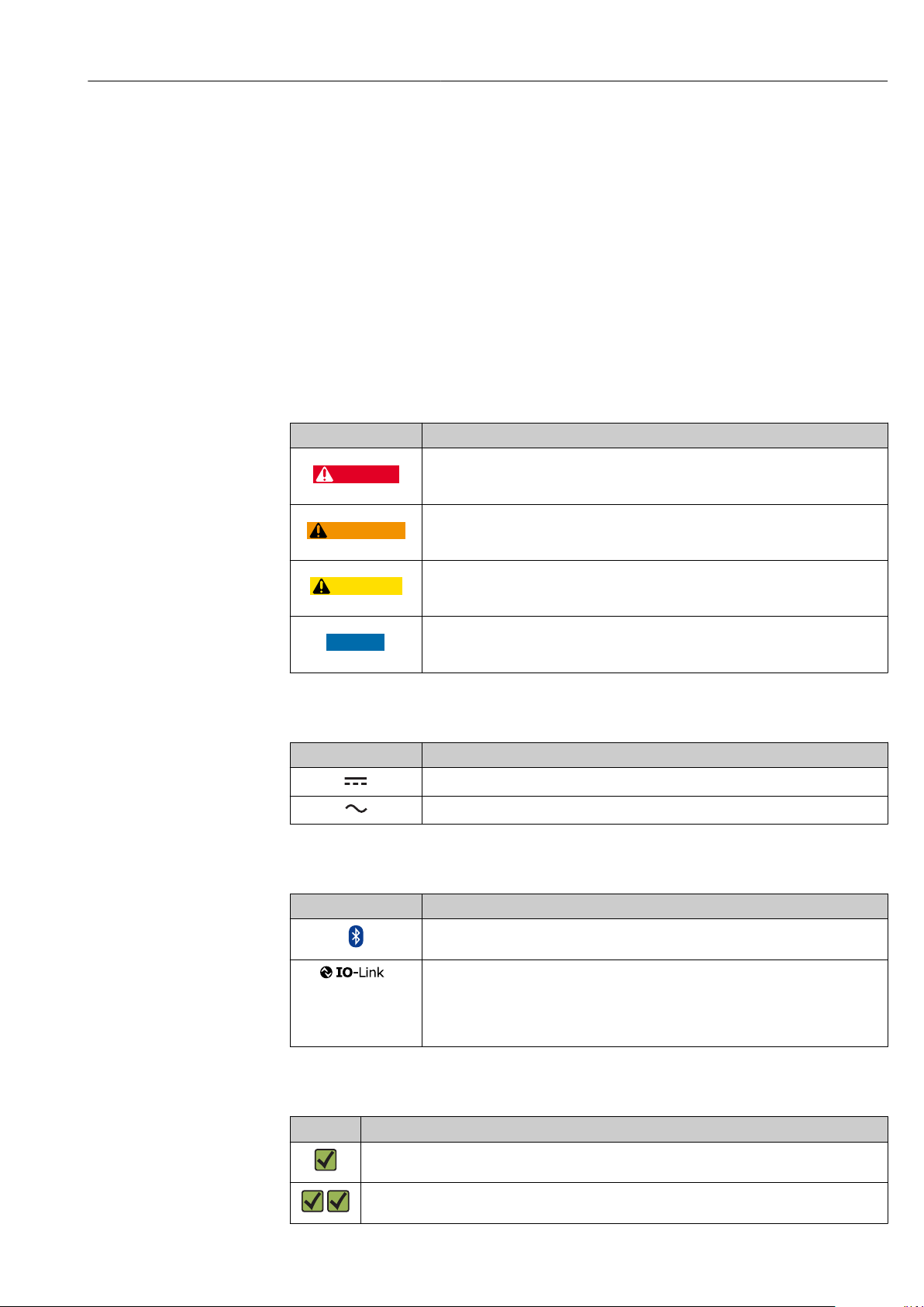
1.2.1 Safety symbols
Symbol Meaning
DANGER!
This symbol alerts you to a dangerous situation. Failure to avoid this situation will
result in serious or fatal injury.
WARNING!
This symbol alerts you to a dangerous situation. Failure to avoid this situation can
result in serious or fatal injury.
CAUTION!
This symbol alerts you to a dangerous situation. Failure to avoid this situation can
result in minor or medium injury.
NOTE!
This symbol contains information on procedures and other facts which do not result in
personal injury.
1.2.2 Electrical symbols
Symbol Meaning
Direct current
Alternating current
1.2.3 Communication symbols
Symbol Meaning
Bluetooth®
Wireless data transmission between devices over a short distance.
® IO-Link
Communications system for connecting intelligent sensors and actuators to an
automation system. The IO-Link technology is standardized under the description
"Single-drop digital communication interface for small sensors and actuators (SDCI)" in
the IEC 61131-9 standard.
1.2.4 Symbols for certain types of information
Symbol Meaning
Permitted
Procedures, processes or actions that are permitted.
Preferred
Procedures, processes or actions that are preferred.
Endress+Hauser 5
Page 6
About this document Picomag IO-Link
A
1.
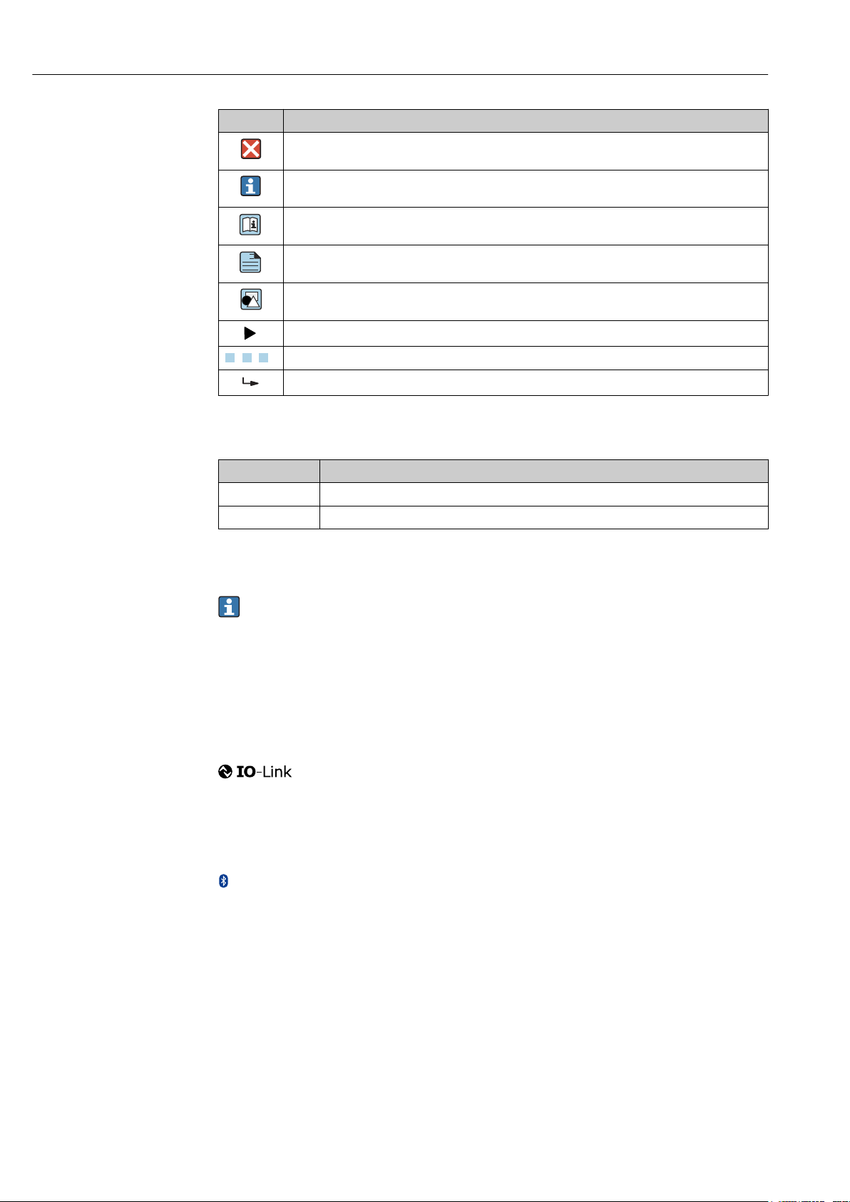
Symbol Meaning
Forbidden
Procedures, processes or actions that are forbidden.
Tip
Indicates additional information.
Reference to documentation
Reference to page
Reference to graphic
Notice or individual step to be observed
, 2., 3.… Series of steps
Result of a step
1.2.5 Symbols in graphics
Symbol Meaning
1, 2, 3, ... Item numbers
A, B, C, ... Views
1.3 Documentation
For an overview of the scope of the associated Technical Documentation, refer to the
following:
• The W@M Device Viewer: Enter the serial number of the measuring device
(www.endress.com/deviceviewer)
• The Endress+Hauser Operations App: Enter the serial number of the measuring
device or scan the 2-D matrix code on the measuring device.
1.4 Registered trademarks
®
Is a registered trademark. It may only be used in conjunction with products and services by
members of the IO-Link Community or by non-members who hold an appropriate license.
For more detailed information on the use of IO-Link, please refer to the rules of the IOLink Community at: www.io.link.com.
Bluetooth® wireless technology
®
The Bluetooth® word mark and logos are registered trademarks owned by the Bluetooth
SIG, Inc. and any use of such marks by Endress+Hauser is under license.
Apple®
Apple, the Apple logo, iPhone, and iPod touch are trademarks of Apple Inc., registered in
the U.S. and other countries. App Store is a service mark of Apple Inc.
Android®
Android, Google Play and the Google Play logo are trademarks of Google Inc.
6 Endress+Hauser
Page 7

Picomag IO-Link Basic safety instructions
2 Basic safety instructions
2.1 Requirements for the personnel
The personnel for installation, commissioning, diagnostics and maintenance must fulfill
the following requirements:
Trained, qualified specialists must have a relevant qualification for this specific function
‣
and task.
Are authorized by the plant owner/operator.
‣
Are familiar with federal/national regulations.
‣
Before starting work, read and understand the instructions in the manual and
‣
supplementary documentation as well as the certificates (depending on the
application).
Follow instructions and comply with basic conditions.
‣
The operating personnel must fulfill the following requirements:
Are instructed and authorized according to the requirements of the task by the facility's
‣
owner-operator.
Follow the instructions in this manual.
‣
2.2 Designated use
Application and media
The measuring device described in these Brief Operating Instructions is intended only for
flow measurement of liquids with a minimum conductivity of 20 µS/cm.
To ensure that the measuring device remains in proper condition for the operation time:
Use the measuring device only for media against which the process-wetted materials
‣
are adequately resistant.
Incorrect use
Non-designated use can compromise safety. The manufacturer is not liable for damage
caused by improper or non-designated use.
WARNING
L
Danger of breakage due to corrosive or abrasive fluids and ambient conditions!
Verify the compatibility of the process fluid with the sensor material.
‣
Ensure the resistance of all fluid-wetted materials in the process.
‣
Keep within the specified pressure and temperature range.
‣
Residual risks
WARNING
L
The electronics and the medium may cause the surfaces to heat up. This presents a
burn hazard!
For elevated fluid temperatures, ensure protection against contact to prevent burns.
‣
2.3 Workplace safety
For work on and with the device:
Wear the required personal protective equipment according to federal/national
‣
regulations.
For welding work on the piping:
Do not ground the welding unit via the measuring device.
‣
Endress+Hauser 7
Page 8

Basic safety instructions Picomag IO-Link
2.4 Operational safety
Risk of injury!
Operate the device in proper technical condition and fail-safe condition only.
‣
The operator is responsible for interference-free operation of the device.
‣
2.5 Product safety
This measuring device is designed in accordance with good engineering practice to meet
state-of-the-art safety requirements, has been tested, and left the factory in a condition in
which it is safe to operate.
It meets general safety standards and legal requirements. It also complies with the EU
directives listed in the device-specific EU Declaration of Conformity. Endress+Hauser
confirms this by affixing the CE mark to the device.
2.6 IT security
Our warranty is valid only if the device is installed and used as described in the Operating
Instructions. The device is equipped with security mechanisms to protect it against any
inadvertent changes to the settings.
IT security measures, which provide additional protection for the device and associated
data transfer, must be implemented by the operators themselves in line with their security
standards.
2.7 Device-specific IT security
2.7.1 Access via the SmartBlue App
Two access levels (user roles) are defined for the device: the Operator user role and the
Maintenance user role. The Maintenance user role is the default setting.
If a user-specific access code is not defined (in the Set access code parameter), the default
setting 0000 continues to apply and the Maintenance user role is automatically enabled.
The device's configuration data are not write-protected and can be edited at all times.
If a user-specific access code has been defined (in the Set access code parameter), all the
parameters are write-protected and the device is accessed with the Operator user role. The
previously defined access code must first be entered again before the Maintenance user
role is enabled and all the parameters can be write-accessed.
2.7.2 Protecting access via a password
Different passwords are available to protect write access to the device parameters or access
to the device via the Bluetooth® interface.
• User-specific access code
Protect write access to the device parameters via the SmartBlue app
• Bluetooth key
The password protects a connection between an operating device (e.g. smartphone,
tablet) and the device via the Bluetooth® interface.
8 Endress+Hauser
Page 9

Picomag IO-Link Basic safety instructions
General notes on the use of passwords
• The access code and Bluetooth key supplied with the device should be changed during
commissioning.
• Follow the general rules for generating a secure password when defining and managing
the access code or Bluetooth key.
• The user is responsible for the management and careful handling of the access code and
Bluetooth key.
2.7.3 Access via Bluetooth® wireless technology
Secure signal transmission via Bluetooth® wireless technology uses an encryption
method tested by the Fraunhofer Institute.
• The device is not visible via Bluetooth® wireless technology without the SmartBlue app.
• Only one point-to-point connection is established between the device and a smartphone
or tablet.
• The Bluetooth® wireless technology interface can be disabled via SmartBlue.
Endress+Hauser 9
Page 10
Incoming acceptance and product identification Picomag IO-Link
1
2
Order code:
Ser. no.:
Ext. ord. cd.:
i
i
Date:
3 Incoming acceptance and product
identification
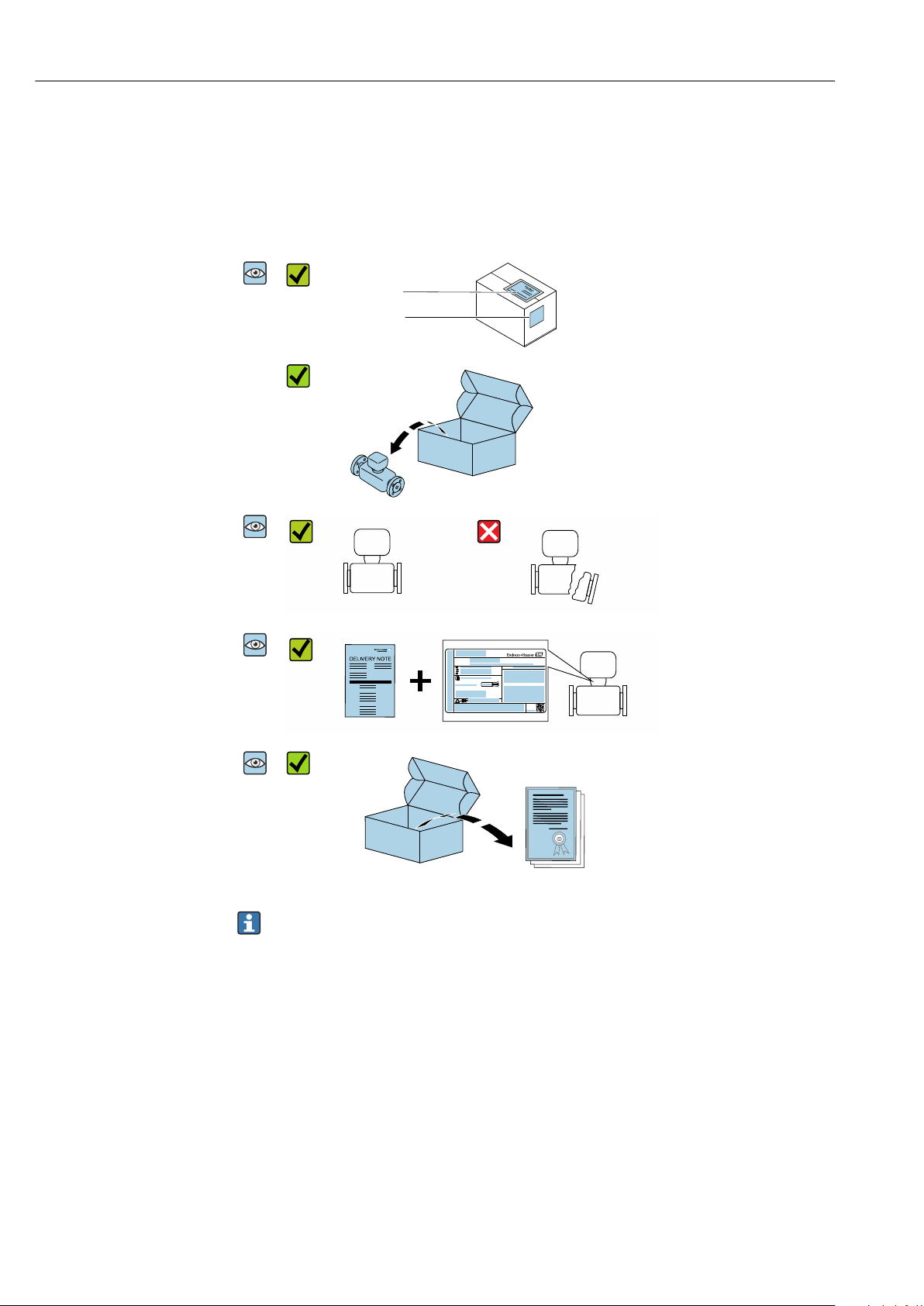
3.1 Incoming acceptance
Are the order codes on the
delivery note (1) and the
product sticker (2) identical?
Are the goods undamaged?
Do the nameplate data
match the ordering
information on the delivery
note?
Is the accompanying safety
data sheet present?
• If one of the conditions is not satisfied, contact your Endress+Hauser Sales Center.
• Depending on the device version, the CD-ROM might not be part of the delivery!
The Technical Documentation is available via the Internet or via the Endress+Hauser
Operations App, see the "Product identification" section .
3.2 Product identification
The following options are available for identification of the measuring device:
• The device label
• Order code with breakdown of the device features on the delivery note
• Enter the serial number on the device label in W@M Device Viewer
(www.endress.com/deviceviewer): all the information about the measuring device is
displayed.
• Enter the serial number on the device label into the Endress+Hauser Operations App or
scan the 2-D matrix code (QR code) on the measuring device with the Endress+Hauser
10 Endress+Hauser
Operations App: all the information about the measuring device is displayed.
Page 11

Picomag IO-Link Incoming acceptance and product identification
3.2.1 Symbols on measuring device
Symbol Meaning
WARNING!
This symbol alerts you to a dangerous situation. Failure to avoid this situation can result in serious
or fatal injury.
Reference to documentation
Refers to the corresponding device documentation.
Endress+Hauser 11
Page 12

Storage and transport Picomag IO-Link
4 Storage and transport
4.1 Storage conditions
Observe the following notes for storage:
Store in the original packaging to ensure protection from shock.
‣
Store in a dry place.
‣
Do not store outdoors.
‣
Storage temperature→ 42
4.2 Transporting the product
Transport the device to the measuring point in the original packaging.
Do not remove protective covers or caps installed on process connections. They
prevent mechanical damage to the sealing surfaces and contamination in the
measuring tube.
4.3 Packaging disposal
All packaging materials are environmentally friendly and 100% recyclable:
Carton in accordance with European Packaging Directive 94/62EC; recyclability is
confirmed by the affixed RESY symbol.
12 Endress+Hauser
Page 13
Picomag IO-Link Installation
h
≥ 0 × DN
5 Installation
5.1 Installation conditions
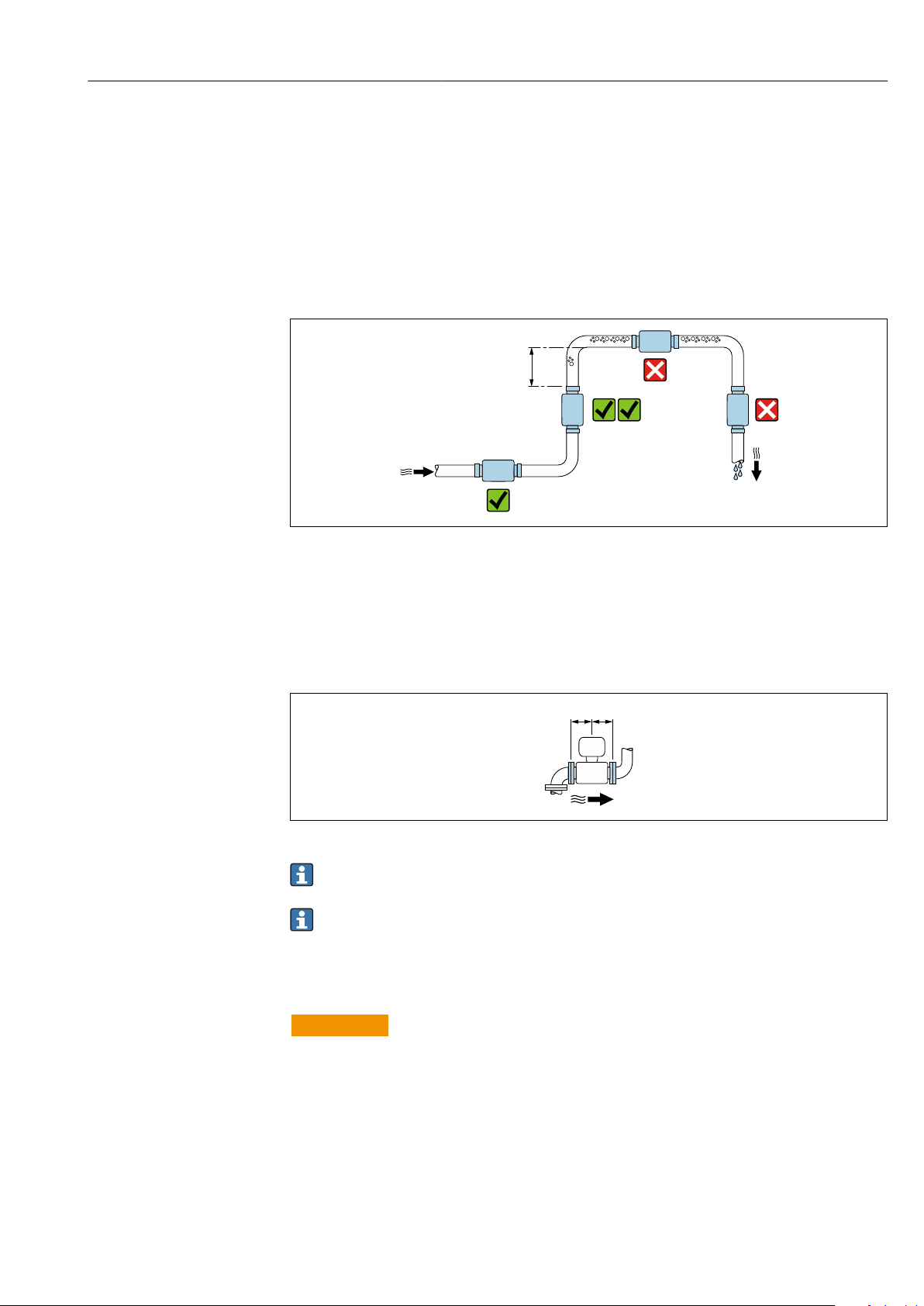
5.1.1 Mounting position
Mounting location
A0032998
Preferably install the sensor in an ascending pipe, and ensure a sufficient distance to the
next pipe elbow: h ≥ 2 × DN
Inlet and outlet runs
No inlet and outlet runs need to be considered.
A0032859
Installation dimensions: information on the dimensions and installed lengths of the
device → 42
The arrow points in the preferred direction of flow. Measurement in the other
direction is also possible.→ 22
5.2 Mounting the measuring device
WARNING
L
Burn hazard!
If medium temperatures or ambient temperatures exceed 50 °C, areas of the housing can
heat to over 65 °C.
Safeguard the housing so that it cannot be touched accidentally.
‣
Endress+Hauser 13
Page 14

Installation Picomag IO-Link
1 12 34 45 53 2
A0033002
1 Pipe
2 Seal (not supplied)
3 Adapter: available adapters → 39
4 Seal (included in delivery)
5 Measuring device connection
14 Endress+Hauser
Page 15
Picomag IO-Link Electrical connection
A
2 WH
1 BN
4 BK
3 BU
1
2
3
4
+
-
!
A
B
B
A
L+
L-
IO2
IO1
6 Electrical connection
6.1 Connection conditions
6.1.1 Requirements for connecting cables
National regulations and standards apply.
Connecting cable M12 × 1 A-coded
Conductor cross-section
Temperature range –10 to +90 °C (+14 to +194 °F)
Degree of protection IP65/67, pollution degree 3
Humidity and moisture Suitable for indoor environments with up to 100% rh (wet and damp locations)
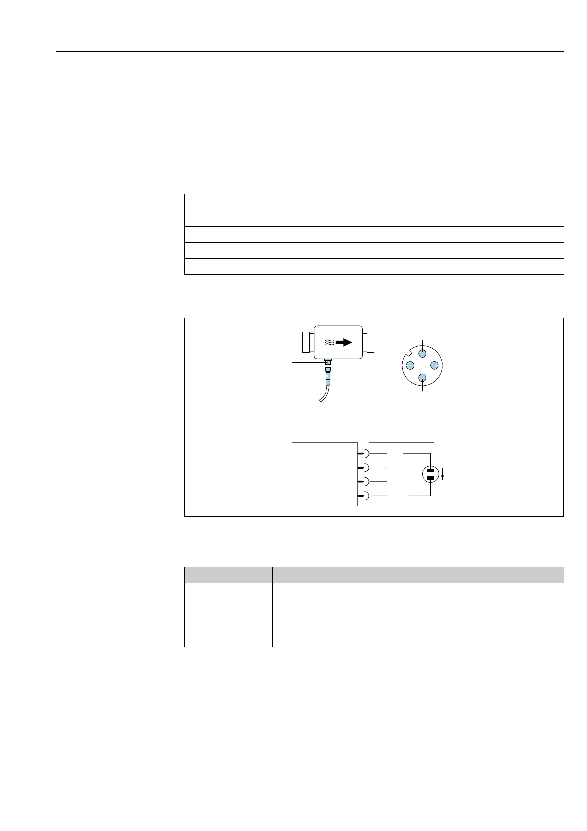
6.1.2 Pin assignment, device plug
At least 0.12 mm2 (AWG26)
A0033004
A Connector (Picomag)
B Socket (Customer side)
Pin Assignment Color Description
1 L+ Brown Supply voltage + (18 to 30 VDC/max. 3 W)
2 IO2 White Input/output 2, can be configured independently of IO1
3 L- Blue Supply voltage -
4 IO1 Black Input/output 1, can be configured independently of IO2
Endress+Hauser 15
Page 16
Electrical connection Picomag IO-Link
1
2
3
4
B
A
L+
L-
1
2
3
4
B
A
L+
L-
1
2
3
4
B
A
L+
L-
1
2
3
4
B
A
L+
L-
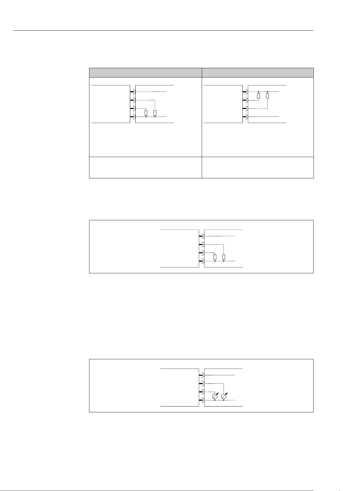
Switch output configuration version
The switching behaviour of IO1 and IO2 can be configured independently of one another.
1)
pnp
A Connector (Picomag)
B Socket (Customer side)
L+ Supply voltage +
L- Supply voltage -
The load is switched to high side L+. The maximum
load current is 250 mA. The output is overloadresistant.
1) positive negative positive (high side switch)
2) negative positive negative (low side switch)
Pulse output configuration version
2)
npn
A0033005
A Connector (Picomag)
B Socket (Customer side)
L+ Supply voltage +
L- Supply voltage -
The load is switched to low side L-. The maximum load
current is 250 mA. The output is overload-resistant.
A0033006
A0033005
1 Pulse output with pnp switching behaviour
A Connector (Picomag)
B Socket (Customer side)
L+ Supply voltage +
L- Supply voltage -
The load is switched to high side L+. The maximum load current is 250 mA. The output is
overload-resistant.
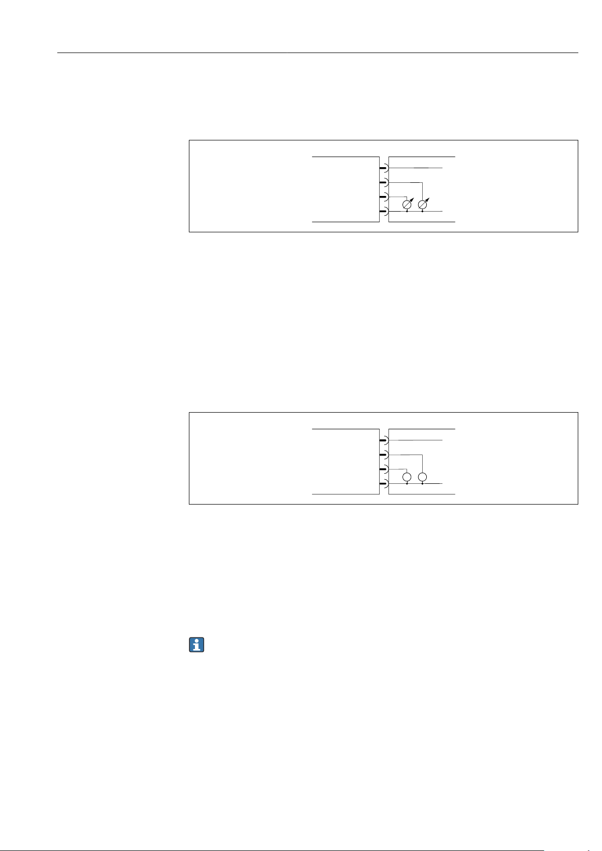
Current output configuration version
A0033007
2 Current output, active, 4 to 20 mA
A Connector (Picomag)
B Socket (Customer side)
L+ Supply voltage +
16 Endress+Hauser
L- Supply voltage -
Page 17
Picomag IO-Link Electrical connection
1
2
3
4
B
A
L+
L-
1
2
3
4
B
A
L+
L-
==
The current flows from the output to L-. The maximum load may not exceed 500 Ω. A
bigger load distorts the output signal.
Voltage output configuration version
A0033007
3 Voltage output, active, 2 to 10 V
A Connector (Picomag)
B Socket (Customer side)
L+ Supply voltage +
L- Supply voltage -
The voltage from the output applies to L-. The load must be at least 500 Ω. The output is
overload-resistant.
Status input configuration version
• 15 V (switch-on threshold)
• 5 V (switch-off threshold)
4 Status input
A Connector (Picomag)
B Socket (Customer side)
L+ Supply voltage +
L- Supply voltage -
Internal resistance: 7.5 kΩ
IO-Link configuration version
Option only available for output 1 in the Output 1→ 23 submenu
A0033008
The measuring device features an IO-Link communication interface with a baud rate of
38,400 and with a second IO function on pin 2. This requires an IO-Link compatible
module (IO-Link master) for operation. The IO-Link communication interface allows direct
access to the process and diagnostics data.
Endress+Hauser 17
Page 18
Electrical connection Picomag IO-Link
1
6.2 Connecting the measuring device
NOTICE
The measuring device may only be installed by properly trained technicians.
Comply with national and international regulations regarding the installation of
‣
electrotechnical systems.
Power supply according to EN 50178, SELV, PELV or Class 2.
‣
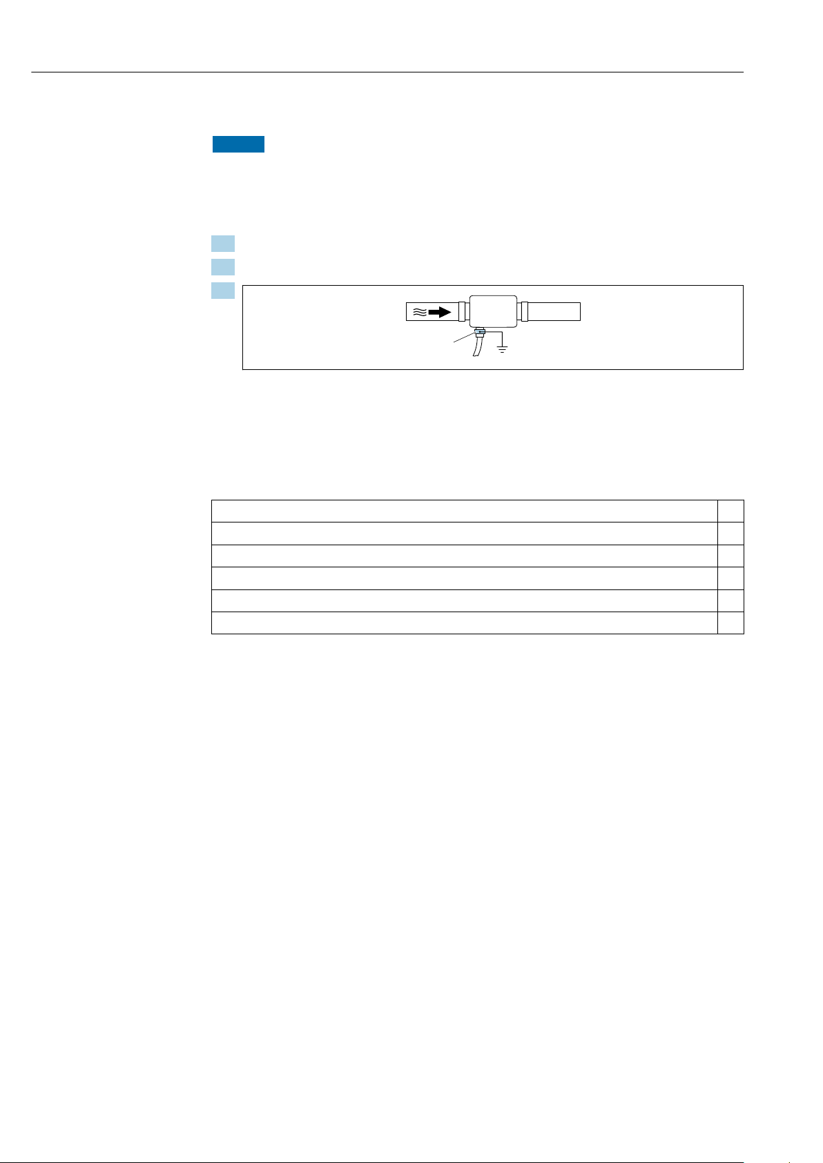
1. De-energize the system.
2. Connect the measuring device via the connector.
3.
A0033003
In the case of non-grounded pipes:
The device must be grounded using the ground terminal accessory.
6.3 Post-connection check
Are cables or the device undamaged (visual inspection)?
Do the cables have adequate strain relief?
Is the connector connected correctly?
Does the supply voltage match the specifications on the measuring device?
Is the pin assignment of the connector correct?
Is the potential equalization established correctly?
18 Endress+Hauser
Page 19

Picomag IO-Link Operation options
7 Operation options
7.1 Access to the operating menu via the SmartBlue app
The device can be operated and configured via the SmartBlue app. In this case, the
connection is established via the Bluetooth® wireless technology interface.
Supported functions
• Device selection in Live List and access to the device (login)
• Configuration of the device
• Access to measured values, device status and diagnostics information
The SmartBlue app is available for free download for Android devices (Google Playstore)
and iOS devices (iTunes Apple Shop) : Endress+Hauser SmartBlue
Directly to the app with the QR code:
System requirements
• Devices with iOS:
iOS9.0 or higher
• Devices with Android:
Android 4.4 KitKat or higher
Download the SmartBlue app:
1. Install and start the SmartBlue app.
A Live List shows all the devices available.
The list displays the devices with the configured tag name. The default setting for
the tag name is EH_DMA_XYZZ (XYZZ = the last 7 digits of the device serial
number).
2. For Android devices, activate GPS positioning (not necessary for devices with IOS)
3. Select the device from the Live List.
The Login dialog box opens.
Logging in:
4. Enter the user name: admin.
5. Enter the initial password: serial number of the device.
When you log in for the first time, a message is displayed advising you to change
the password.
6. Confirm your entry.
The main menu opens.
7. Optional: Change the password:
A0033202
Navigate through the various items of information about the device: swipe the screen
to the side.
Endress+Hauser 19
Page 20

System integration Picomag IO-Link
8 System integration
The measuring device has an IO-Link communication interface. The IO-Link interface
allows direct access to process and diagnostics data and enables the user to configure the
measuring device on the fly.
Properties:
• IO-Link Specification: Version 1.1
• IO-Link Smart Sensor Profile 2nd Edition
• SIO mode: yes
• Speed: COM2 (38.4 kBaud)
• Minimum cycle time: 10 ms
• Process data width: 120 bit
• IO-Link data storage: yes
• Block configuration: no
• Device operational: The measuring device is operational 4 seconds after the supply
voltage is applied
More information on IO-Link is available at www.io-link.com
Overview of the entire IO-Link ISDU parameter list → 49
8.1 Overview of device description files
Current version data for the device
Firmware version 01.01.zz • On the title page of the Operating Instructions
• On the device label
• Firmware version system parameter
Release date of firmware version 05.2019 ---
Profile version • 1.1
• Smart Sensor Profile
---
8.2 Device master file
In order to integrate field devices into a digital communication system, the IO-Link system
needs a description of the device parameters, such as output data, input data, data format,
data volume and supported transmission rate.
These data are available in the device master file (IODD
Master via generic modules when the communication system is commissioned.
The IODD can be downloaded as follows:
• Endress+Hauser: www.endress.com
• IODDfinder: ioddfinder.io-link.com
1)
) which is provided to the IO-Link
1) IO Device Description
20 Endress+Hauser
Page 21

Picomag IO-Link Commissioning
9 Commissioning
9.1 Switching ON the measuring device
Once the supply voltage has been switched on, the measuring device adopts the normal
mode after a maximum of 4 s. During the start-up phase, the outputs are in the same state
as the measuring device in the switched-off state.
9.2 Overview of the operating menu
Overview of the operating menu
Guidance
Diagnostics
System
▸ Identification
▸ System units
▸ Sensor
▸ Output 1
▸ Output 2
▸ Totalizer
▸ Display
▸ Security
▸ Data management
▸ Actual diagnostics
▸ Simulation
→ 21
→ 22
→ 22
→ 23
→ 23
→ 28
→ 29
→ 30
→ 30
→ 31
→ 31
▸ Data management
▸ Firmware
→ 31
→ 31
9.3 Configuring the measuring device
9.3.1 Identification
The device tag and the user level can be changed in the Identification submenu.
Navigation
Menu: "Guidance" → Identification
Endress+Hauser 21
Page 22

Commissioning Picomag IO-Link
9.3.2 Configuring system units
In the System units submenu, you can configure the units of all measured values.
Navigation
Menu: "Guidance" → System units
Parameter overview with brief description
Parameter Description Selection Factory setting
Volume flow unit Select volume flow unit. • l/s, m³/h, l/min, l/h
• gal/min (us), fl. oz/min
Volume unit Select volume unit. • ml, l, m³
• fl. oz (us), gal (us)
Temperature unit Select temperature unit. • °C
• °F
Totalizer unit Select totalizer unit. • l, m³
• 1 000 l, 1 000 m
• fl. oz (us), gal (us)
• 1 000 gal (us)
Conductivity unit Select the unit for conductivity. • µS/cm
• S/m
• ms/cm
3
l/min
ml
°C
m³
µS/cm
9.3.3 Setting the installation direction and measurement
The Sensor submenu contains parameters for specific settings of the measuring device.
Navigation
Menu: "Guidance" → Sensor
Parameter overview with brief description
Parameter Description Selection/input Factory setting
Installation
direction
On value Enter the on value for low
Damping Enter the time constant for
Select the installation
direction.
flow cut off.
damping the flow
measured value.
• Flow in arrow direction (forwards)
Positive flow measurement in the direction of the arrow.
• Flow against arrow direction (backwards)
Positive flow measurement in the opposite direction of the
arrow.
Positive floating point number
A flow measured value that is less than the value of the on
value forces the display to zero. In the event of plant
downtime, this prevents the totalizer from continuing to
totalize even though there is no flow.
0 to 10 s 0 s
Flow in arrow direction (forwards)
Depends on the nominal diameter:
DN 15 (½"):
0.05 l/min (0.013 gal/min)
DN 20 (¾"):
0.1 l/min (0.026 gal/min)
DN 25 (1"):
0.2 l/min (0.052 gal/min)
DN 50 (2"): 1.5 l/min (0.4 gal/min)
22 Endress+Hauser
Page 23

Picomag IO-Link Commissioning
9.3.4 Configuring the IO modules
The measuring device has two signal inputs or signal outputs that can be configured
independently of one another:
• Current output→ 23
• Pulse output→ 24
• Switch output→ 25
• Voltage output→ 26
• Status input → 28
Navigation
Menu: "Guidance" → Output 1
Menu: "Guidance" → Output 2
Parameter overview with brief description
Parameter Description Selection Factory setting
Output 1 Select the operating mode of output 1. • Pulse output
• Current output
• Switch output
• Voltage output
• Digital input
• IO-Link
• Off
Output 2 Select the operating mode of output 2. • Current output
• Switch output
• Voltage output
• Digital input
• Off
IO-Link
Off
Configuring the current output
The Current output submenu contains all the parameters that must be configured for the
configuration of the current output.
The output is used to output process variables by analog means in the form of a 4-20 mA
current.
Navigation
Menu: "Guidance" → Output 1 → Current output
Menu: "Guidance" → Output 2 → Current output
Parameter overview with brief description
Parameter Description Selection/input Factory setting
Assign current output Select process variable for current output. • Off
• Volume flow
• Temperature
• Conductivity
4 mA value Enter 4 mA value. Floating point number with sign 0 l/min
20 mA value Enter 20 mA value. Floating point number with sign Depends on the nominal diameter:
Volume flow
DN 15 (½"): 25 l/min (6.6 gal/min)
DN 20 (¾"): 50 l/min (13.2 gal/min)
DN 25 (1"): 100 l/min (26.4 gal/min)
DN 50 (2"): 750 l/min (198.1 gal/min)
Endress+Hauser 23
Page 24

Commissioning Picomag IO-Link
A = 0
B
Q
mA
20
16
12
8
4
A = 0
B
Q
mA
20
16
12
8
4
Unidirectional flow measurement (Q), conductivity measurement
A0035753
A Lower range value = 0
B Upper range value
Q Flow
• Current I is linearly interpolated between lower range value (A) and upper range value
(B).
• The output range ends at 20.5 mA.
Bidirectional flow measurement (Q), temperature measurement (T)
A0035754
A Lower range value
B Upper range value
Q Flow
• Current I is linearly interpolated between lower range value (A) and upper range value
(B).
• Rather than having a hard upper and lower limit, the output range ends at 20.5 mA at
the top end and at 3.8 mA at the bottom end.
Configuring the pulse output
The Pulse output submenu contains all the parameters that must be configured for the
configuration of the pulse output.
Navigation
Menu: "Guidance" → Output 1
24 Endress+Hauser
Page 25

Picomag IO-Link Commissioning
Menu: "Guidance" → Output 2
Parameter overview with brief description
Parameter Description User entry Factory setting
Value per pulse Enter the value for the pulse output. Floating point number with sign
Depends on the nominal diameter:
DN 15 (½"): 0.5 ml
DN 20 (¾"): 1.0 ml
DN 25 (1"): 2.0 ml
DN 50 (2"): 10.0 ml
The current pulse repetition frequency is calculated from the current flow and the
configured pulse value:
Pulse repetition frequency = flow/pulse value
Example
• Flow: 300 ml/min
• Pulse value: 0.001 l
• Pulse repetition frequency = 5 000 Pulse/s
The pulse output only outputs positive flow components in the set installation direction.
Negative flow components are ignored and not balanced.
Configuring the switch output
The Switch output submenu contains all the parameters that must be configured for the
configuration of the switch output.
Navigation
Menu: "Guidance" → Output 1
Menu: "Guidance" → Output 2
Parameter overview with brief description
Parameter Description Selection/input
Polarity Select the switching
behavior.
Switch output
function
• NPN (low-side-switch)
Switches load to low side to L-
• PNP (high-side-switch)
Switches load to high side to L+
• Off
The switch output is permanently switched off (open, non-conductive).
• On
The switch output is permanently switched on (closed, conductive).
• Diagnostic behavior
The output switches when an event with the status signal F occurs
• Limit volume flow
Indicates if a specified limit value is reached for the process variable.
• Limit temperature
Indicates if a specified limit value is reached for the process variable.
• Limit conductivity. Indicates if a specified limit value is reached for the process
variable.
• Limit volume totalizer Range volume totalizer
• Range volume flow
• Range temperature
• Range conductivity
• Range volume totalizer
• Empty pipe detection
Output switches off if empty pipe detection is activated.
Factory
setting
PNP (highside-switch)
Off
Endress+Hauser 25
Page 26

Commissioning Picomag IO-Link
1
0
A
B
t
C
1.1
1.2
Q / T
Q / T
1
0
A
B
t
C
2.1
2.2
Q / T
1
0
A
t
D D
3.1
3.2
B
B
A
Q / T
1
0
A
B
t
D D
4.1
4.2
A
B
Parameter Description Selection/input
Switch-on value Enter the measured
value for the switch-on
value.
Switch-off value Enter the measured
value for the switch-off
value.
Floating point number with sign 1 000 m³/h
Floating point number with sign 1 000 m³/h
Limit switched on Limit switched off
A0034163
1.1 Input variables
1.2 Switch output
A Switch-on value
B Switch-off value
C Hysteresis
Range switched on Range switched off
Factory
setting
A0034164
2.1 Input variables
2.2 Switch output
A Switch-on value
B Switch-off value
C Hysteresis
A0034165
3.1 Input variables
3.2 Switch output
A On-value (lower range limit)
B Off-value (upper range limit)
D Window
4.1 Input variables
4.2 Switch output
A On-value (lower range limit)
B Off-value (upper range limit)
D Window
Configuring the voltage output
The Voltage output submenu contains all the parameters that must be configured for the
configuration of the voltage output.
Navigation
26 Endress+Hauser
Menu: "Guidance" → Output 1
A0034166
Page 27

Picomag IO-Link Commissioning
A = 0
B
Q
V
10
8
6
4
2
0
B
Q
V
10
8
4
2
A
6
Menu: "Guidance" → Output 2
Parameter overview with brief description
Parameter Description Selection/input Factory setting
Assign voltage output Select process variable for voltage output. • Off
• Volume flow
• Temperature
• Conductivity
2 V value Enter the lower range value. Floating point number with sign 0 l/min
10 V value Enter the upper range value. Floating point number with sign Depends on the nominal diameter:
Volume flow
DN 15 (½"): 25 l/min
DN 20 (¾"): 50 l/min
DN 25 (1"): 100 l/min
DN 50 (2"): 750 l/min
Unidirectional flow measurement (Q), conductivity measurement
A0032995
A Lower range value = 0
B Upper range value
Q Flow
• Voltage U is linearly interpolated between lower range value (A) and upper range value
(B).
• The output range ends at 10.25 V.
Bidirectional flow measurement (Q), temperature measurement (T)
A0032996
A Lower range value
B Upper range value
Endress+Hauser 27
Q Flow
Page 28

Commissioning Picomag IO-Link
• Voltage U is linearly interpolated between lower range value (A) and upper range value
(B).
• Rather than having a hard upper and lower limit, the output range ends at 10.25 V at
the top end and at 1.9 V at the bottom end.
Configuring the status input
The Digital input submenu contains all the parameters that must be configured for the
configuration of the digital input.
The input is used to control an action with an external voltage signal. The minimum pulse
duration is 100 ms.
Navigation
Menu: "Guidance" → Output 1
Menu: "Guidance" → Output 2
Parameter overview with brief description
Parameter Description Selection Factory setting
Active level Select the switching behavior of the digital input. • High
Input reacts to high level
• Low
Input reacts to low level
Assign status input Select the function for the status input. • Off
• Reset totalizer
Resets the totalizer
• Flow override
– Flow measured value = 0
– Does not affect the temperature measurement
High
Reset totalizer
9.3.5 Totalizer
The totalizer can be reset with the Reset totalizer submenu.
Navigation
Menu: "Guidance" → Totalizer
Parameter overview with brief description
Parameter Description Display/options Factory setting
Volume totalizer Enter value. Floating point number with sign 0 m
Reset totalizer Reset the totalizer. • Cancel
The totalizer is not reset.
• Reset + totalize
The totalizer is reset.
3
Cancel
28 Endress+Hauser
Page 29

Picomag IO-Link Commissioning
A
A
A
9.3.6 Configuring the display
The Display submenu contains all the parameters that can be configured for the
configuration of the onsite display.
Navigation
Menu: "Guidance" → Display
Parameter overview with brief description
Parameter Description Selection/input Factory setting
Format display Select how measured values are
shown on the display.
Rotation display Select local display rotation. • Auto (automatic)
Display value 1st line + display value 2nd line:
• Volume flow + temperature
• Volume flow + totalizer
• Temperature + totalizer
• Volume flow + conductivity
• Totalizer + conductivity
• Temperature + conductivity
4 display values:
Volume flow + temperature + totalizer + conductivity
2 display values (multiplex):
Volume flow +totalizer / temperature + conductivity
• The display rotates automatically depending on the installation position
• 0°
• Can be read in the horizontal installation position with flow from left to
right
Volume flow +
temperature
Auto
A0033013
• 90°
• Can be read in the vertical installation position with flow from bottom to
top
A0033014
• 180°
• Can be read in the horizontal installation position with flow from right to
left
A0033015
Endress+Hauser 29
Page 30

Commissioning Picomag IO-Link
A
Parameter Description Selection/input Factory setting
• 270°
• Can be read in the vertical installation position with flow from top to
bottom
A0033016
Backlight Set the intensity of the
backlighting.
0 to 100 % 50 %
9.3.7 Security
The Security submenu contains all the parameters required to define a new access code
and to configure the Bluetooth connection.
Navigation
Menu: "Guidance" → Security
Parameter overview with brief description
Parameter Description Entry/selection/display
Define access code Enter a user-specific access code to restrict write access to
parameters.
Bluetooth Enable or disable the Bluetooth® wireless technology
interface.
If the interface is disabled, it can only be re-enabled
by tapping the device.
Change Bluetooth
password
Change Bluetooth password Character string comprising numbers, letters and
Max. 4-digit string of numbers 0000
• Disable
– Disable the interface.
– The connection to the measuring device is
torn down.
• Enable
special characters
Enable Bluetooth by tapping the device
1. Activate Bluetooth by tapping on the housing three times.
2. Establish a connection to the device via the SmartBlue app.
9.3.8 Data management
Export configuration as report
The device configuration can be exported as a PDF report and saved in the mobile terminal
or forwarded with this function.
Save configuration to file
The device configuration is saved in the app. The saved device configuration can be
transferred to another Picomag using the System → "Load configuration from app"
function.
Navigation
Menu: "Guidance" → Data management
Factory
setting
Enable
-
30 Endress+Hauser
Page 31

Picomag IO-Link Commissioning
9.4 Pending diagnostic events
Navigation
Menu: "Diagnostics"
Parameter overview with brief description
Parameter Prerequisite Description Display
Actual diagnostic A diagnostic event has occurred. Displays the current diagnostic event along with the
diagnostic information.
If two or more messages occur simultaneously, the
message with the highest priority is shown on the
display.
Simulation process
variable
Volume flow value Enter the value for volume flow
Temperature value Enter the value for temperature
Conductivity value Enter the value for conductivity
Enable variables for the simulation of
the process variables.
simulation.
simulation.
simulation
• Off
Variables are disabled.
• On
Variables are enabled.
Positive floating point number –
Positive floating point number –
Positive floating point number –
Symbol for
diagnostic behavior,
diagnostic code and
short message.
-
9.4.1 Simulation
The Simulation submenu enables you to simulate, without a real flow situation, various
process variables in the process and the device alarm mode and to verify downstream
signal chains (switching valves or closed-control loops).
Navigation
Menu: "Diagnostics"
Parameter overview with brief description
Parameter Description Selection/input
Simulation process
variable
Volume flow value Enter the value for volume flow simulation. Positive floating point number –
Temperature value Enter the value for temperature simulation. Positive floating point number –
Conductivity value Enter the value for conductivity simulation Positive floating point number –
Activate the simulation of process variables. • Off
Simulation is deactivated.
• On
Simulation is activated.
Deactivate the simulation again once the test has
been performed.
Factory
setting
Off
9.5 System
The System submenu contains all the parameters that can be used for the administration
of the device.
Navigation
Endress+Hauser 31
Page 32

Commissioning Picomag IO-Link
Menu: "System"
Parameter overview with brief description
Parameter Description Entry/selection/display Factory setting
Access status tooling Displays the access status. • Operator
• Maintenance
Enter access code Enter the access code.
Restrict write access to parameters in order to protect the device
configuration from unauthorized modification.
Device reset Reset the entire device configuration or some of the configuration to a
defined state.
Export configuration as
report
Save configuration to file The device configuration is saved in the app. The saved device
Load Configuration from file The saved device configuration can be uploaded to a new device with
Reset Device - - -
Firmware version - - -
Firmware update - - -
The device configuration can be exported as a PDF report and saved in
the mobile device or forwarded with this function.
configuration can be transferred to another Picomag using the System
→ "Load configuration from file" function.
this function.
Max. 4-digit string of
numbers
• Cancel
• To factory defaults
• Restart device
- -
- -
- -
Maintenance
0000
Cancel
32 Endress+Hauser
Page 33

Picomag IO-Link Operational
Xxxxx
2
1
3
4 5
6
I01:
I02:
BT:
SNo:
SW:
PIN4
PIN2
/
/
/
/
/
7
8
9
11
12
13
10
10 Operational
10.1 Offline quick view of the configuration
Tap the top of the housing (e.g. the arrow indicating the flow direction) with your knuckles
or an object to display an overview of preconfigured parameters.
A0036432
5 Information in the status layout, overview of the preconfigured parameters
1 I/O area
2 Bluetooth area
3 Identification area
4 I/O type 1
5 I/O current value type 1
6 I/O type 2
7 I/O current value type 2
8 I/O assignment type 1
9 I/O assignment type 2
10 Bluetooth module status
11 Bluetooth connection status
12 Serial number
13 Software version
I/O area (in brackets: item number → 5, 33)
I/O type ( 4, 6) I/O assignment (8, 9) I/O current value (5, 7)
S-Out • Alrt
• LimQ
• LimT
• LimV
• Lims
• WinQ
I-Out • s
• Q
• T
U-Out • s
• Q
• T
S-In • RsT
• Ovrd
P-Out Q PNPOn PNPOff
IO-L PD • Dis.
Endress+Hauser 33
Off – –
• WinT
• WinV
• Wins
• EPD
• Off
• On
Off xx.x mA
Off xx.x V
Off Low High
• PNPOn
• PNPOff
• Start
• NPNOn
• NPNOff
• Preop.
• Oper.
Page 34

Operational Picomag IO-Link
Bluetooth area (in brackets: item number → 5, 33)
Bluetooth module status (12) Bluetooth connection status (13)
On Dis./Con.
Off Dis.
34 Endress+Hauser
Page 35

Picomag IO-Link Diagnostics and troubleshooting
11 Diagnostics and troubleshooting
11.1 General troubleshooting
For local display
Error Possible causes Solution
Local display dark and no output
signals
For output signals
Error Possible causes Solution
Device shows correct value on local
display, but signal output is
incorrect, though in the valid range.
Device measures incorrectly. Configuration error or device is
Supply voltage does not match the
value indicated on the nameplate.
The polarity of the supply voltage is
wrong.
The connecting cables are not
connected correctly.
Configuration error Check and correct the parameter
operated outside the application.
Apply the correct supply voltage
→ 41.
Correct the polarity.
Check the cable connection and
correct if necessary.
configuration.
1. Check and correct parameter
configuration.
2. Observe limit values specified in
the "Technical Data".
For access
Error Possible causes Solution
Measuring device not in
smartphone or tablet live list
No communication with device via
SmartBlue app
Login via SmartBlue app not
possible
Device cannot be operated via
SmartBlue app
No write access to parameters Current user role has limited access
Bluetooth communication is
disabled
No Bluetooth connection Enable Bluetooth function on
Device is being put into operation
for the first time
Incorrect password entered Enter correct password.
Password forgotten Contact Endress+Hauser Service.
authorization
1. Check whether the Bluetooth
logo is visible on the local display or
not.
2. Re-enable Bluetooth
communication by tapping the
device three times.
smartphone or tablet.
The device is already connected
with another smartphone/tablet.
Enter initial password (device serial
number) and change.
1. Check user role
2. Enter correct customerspecific access code → 19.
Endress+Hauser 35
Page 36

Diagnostics and troubleshooting Picomag IO-Link
Xxxxxxx
F 1 8 0
T E M P . C I R C . F A I L .
Xxxxxxx
C 4 4 6
I / O 1 O V E R L O A D
Xxxxxxx
S 9 6 2
E M P T Y P I P E
?
?
?
11.2 Diagnostic information on local display
11.2.1 Diagnostic message
Faults detected by the self-monitoring system of the measuring device are displayed as a
diagnostic message in alternation with the operational display.
Diagnostic message
Alarm Function check Warning
A0033011
A0033010
If two or more diagnostic events are pending simultaneously, only the message of the
diagnostic event with the highest priority is shown.
Status signals
The status signals provide information on the state and reliability of the device by
categorizing the cause of the diagnostic information (diagnostic event).
The status signals are categorized according to VDI/VDE 2650 and NAMUR
Recommendation NE 107: F = Failure, C = Function Check, S = Out of Specification
Symbol Meaning
Failure
An operating error has occurred. The measured value is no longer valid.
Function check
The device is in simulation mode.
Out of specification
The device is being operated:
• Outside its technical specification limits (e.g. outside the process temperature range)
• Outside of the configuration carried out by the user (e.g. maximum flow in parameter 20 mA value)
A0033009
Diagnostic behavior
Diagnostic message Meaning
Alarm
• Measurement is interrupted.
• Signal outputs and totalizers assume the defined alarm condition.
• A diagnostic message is generated.
Function check
Process measured values are simulated to test the outputs/wiring.
• IO1/IO2 overload
• Flow override is active
Warning
• Measurement is resumed.
• Measuring operation with limited accuracy
• The signal outputs and totalizers are not affected.
• A diagnostic message is generated.
36 Endress+Hauser
Page 37

Picomag IO-Link Diagnostics and troubleshooting
Diagnostics behavior of outputs
Output Diagnostic behavior
Switch output • Setting for reporting events with the status signal F
• Switch output is switched on if an event occurs
• No further response to events with other status signals
Pulse output • Pulse output stops if events with the status signal F occur
• No further response to events with other status signals
Totalizer • Totalizing stops if events with the status signal F occur
• No further response to events with other status signals
Current output • 3.5 mA output to report events with the status signal F
• No further response to events with other status signals
Voltage output • 1.75 V output to report events with the status signal F
• No further response to events with other status signals
IO-Link • All events reported to the Master
• Events read and processed further by the Master
11.3 Overview of diagnostic events
Diagnostic
event
181 Coil. circ. fail. Coil/frequency failure
180 Temp. circ.
201 Device fail. No communication to
283 Memory fail. CRC failure Reset to factory settings. F
446 I/O 1
447 I/O 2
485 Simulation
453 Flow override Flow override active (via
441 I-Out 1 range I-output 1 at range limit Adjust parameter or process. S
444 U-Out 1
443 P-Out 1
442 I-Out 2 range I-output 2 at range limit Adjust parameter or process. S
445 U-Out 2
962 Empty pipe Pipe is completely or
834 Temperat.
841 Flow range Flow rate outside the
Event text Reason Remedial measures
Replace the measuring
fail.
overload
overload
act.
range
range
range
range
Coil current PWM
outside tolerance range
Temperature sensor
open circuit/shortcircuit
ADC/Nordic/BMA
Overload at output 1 Increase load impedance. C
Overload at output 2 Increase load impedance. C
Measured value
simulation active (via
remote configuration)
auxiliary input)
U-output 1 at range
limit
P-output 1 at range
limit
U-output 2 at range
limit
partially empty
Medium temperature
outside the permitted
range
permitted range
device.
Replace the measuring
device.
Replace the measuring
device.
– C
– C
Adjust parameter or process. S
Adjust parameter or process. S
Adjust parameter or process. S
Adjust the process. S
Adjust the process. S
Adjust the process. S
Status signal [ex-
factory]
F
F
F
Endress+Hauser 37
Page 38

Diagnostics and troubleshooting Picomag IO-Link
11.4 Device information
The Device info submenu contains all parameters that display different information for
device identification.
Navigation
Menu: "System" → Device info
Parameter overview with brief description
Parameter Description User interface
Device name Displays the name of the measuring device. Picomag
Device tag Shows name of measuring point. Max. 32 characters, such as letters, numbers or special characters (e.g. @,
%, /).
Serial number Displays the serial number of the measuring device. Max. 11-digit character string comprising letters and numbers.
Firmware version Displays the device firmware version installed. Character string in the format xx.yy.zz
Extended order code Displays the extended order code. Character string composed of letters, numbers and certain punctuation
marks (e.g. /).
The following information is shown on the display by tapping once on the housing:
• Status and values for output 1
• Status and values for output 2
• Bluetooth status (On/Off)
• Serial number
• Software version
11.5 Firmware history
Release
date
09.2017 01.00.zz Original firmware Operating
05.2019 01.01.zz • Conductivity
Firmware
version
Firmware
changes
measurement
• Export configuration
report
• Save/load
configuration
• Bug fix
Documentation type Documentation
Instructions
Operating
Instructions
BA01697D/06/EN/01.17
BA01697D/06/EN/02.17
BA01697D/06/EN/03.17
BA01697D/06/EN/04.19
38 Endress+Hauser
Page 39

Picomag IO-Link Accessories
12 Accessories
Various accessories are available for the device, and can be ordered with the device or at a
later stage from Endress+Hauser. An up-to-date overview of accessories is available from
your local Endress+Hauser Sales Center or on the product page of the Endress+Hauser
website: www.endress.com.
Adapter set
Order number Description
71355698 G½" to G³⁄₈" external thread
71355699 G½" to R³⁄₈" external thread
71355700 G½" to NPT³⁄₈" external thread
71355701 G½" to G½" internal thread
71355702 G½" to R½" external thread
71355703 G½" to NPT½" external thread
71355704 G½" to ½" TriClamp
71355705 G³⁄₄" to R³⁄₄" external thread
71355706 G³⁄₄" to NPT³⁄₄" external thread
71355707 G³⁄₄" to G³⁄₄" internal thread
71355708 G³⁄₄" to R³⁄₄" TriClamp
71355709 G1" to R1" external thread
71355710 G1" to NPT1" external thread
71355711 G1" to G1" internal thread
71355712 G1" to 1" TriClamp
71355713 G2" to R1" external thread
71355714 G2" to R2" external thread
71355715 G2" to NPT1½" external thread
71355716 G2" to NPT2" external thread
71355717 G2" to G1½" external thread
71355718 G2" to G2" internal thread
71355719 G2" to 2" TriClamp
71355720 G2" to 2" Victaulic
71399930 G2" to 54mm press fitting
Cable set
Order number Description
71349260 2m/6.5ft, straight, 4x0.34, M12, PUR
71349261 5m/16.4ft, straight, 4x0.34, M12, PUR
71349262 10m/32.8ft, straight, 4x0.34, M12, PUR
71349263 2m/6.5ft, 90 degrees, 4x0.34, M12, PUR
71349264 5m/16.4ft, 90 degrees, 4x0.34, M12, PUR
71349265 10m/32.8ft, 90 degrees, 4x0.34, M12, PUR
Endress+Hauser 39
Page 40

Accessories Picomag IO-Link
Seal set
Order number Description
71354741 DMA15 Cent.3820
71354742 DMA20 Cent.3820
71354745 DMA25 Cent.3820
71354746 DMA50 Cent.3820
Ground terminal set
Order number Description
71345225 Ground terminal
40 Endress+Hauser
Page 41

Picomag IO-Link Technical data
13 Technical data
13.1 Input
Measured variables • Volume flow
• Temperature
• Totalizer
• Conductivity
Measuring range DN 15 (½"): 0.05 to 25 l/min (0.013 to 6.6 gal/min)
DN 20 (¾"): 0.1 to 50 l/min (0.026 to 13.2 gal/min)
DN 25 (1"): 0.2 to 100 l/min (0.052 to 26.4 gal/min)
DN 50 (2"):1.5 to 750 l/min (0.4 to 198.1 gal/min)
Digital input • High or low active
• Switch-on level 15 V
• Switch-off level 5 V
• Internal resistance 7.5 kOhm
13.2 Output
Output Max. load
Current output 500 Ω
Load must not be greater
Voltage output 500 Ω
Load resistance must not be smaller
Signal on alarm • Status signal (as per NAMUR Recommendation NE 107)
• Plain text display with remedial action
Switch output • Switching behaviour: pnp or npn
• Max. load 250 mA
13.3 Power supply
Supply voltage range 18 to 30 VDC (SELV, PELV, Class 2)
Power consumption Max. 3 W [w/o outputs IO1 and IO2, 120 mA (+ 2× 250 mA with
I/Os)]
13.4 Performance characteristics
Volume flow measurement
Maximum measured error ±0.8 % o.r.±0.2 % o.f.s.
Repeatability ±0.2 % o.r.
Response time The response time depends on the configuration (damping).
Medium temperature measurement
Maximum measured error ±2.5 °C
Repeatability ±0.5 °C
Conductivity measurement
Repeatability ±5 %o.r.±5 µS/cm
13.5 Installation
→ 13
Endress+Hauser 41
Page 42

Technical data Picomag IO-Link
B
A
C D
E
F
G
H
I
= =
K
13.6 Environment
Ambient temperature range –10 to +60 °C (+14 to +140 °F)
Storage temperature –25 to +85 °C (–13 to +185 °F)
Degree of protection IP65/67, pollution degree 3
Humidity and moisture Suitable for indoor environments with up to 100% rh (wet and damp
locations)
Operating altitude up to 2 000 m
Shock resistance 20 g (11 ms) in accordance with IEC/EN60068-2-27
Vibration resistance Acceleration up to 5 g (10 to 2 000 Hz) in accordance with IEC/
EN60068-2-6
Electromagnetic compatibility (EMC) According to IEC/EN61326 and/or IEC/EN55011 (Class A)
13.7 Process
Medium temperature range • –10 to +70 °C (+14 to +158 °F)
• Permissible short-term temperature, maximum one hour:
85 °C (185 °F)
Repetition after 4 hours at the earliest
Medium properties Liquid, conductivity > 10 µS/cm
Pressure Max. 16 bar
rel
13.8 Mechanical construction
A0033012
Dimensions in SI units
DN A
[mm]B[mm]C[mm]D[mm]
15 110 73 40.5 69.5 M12 × 1 43 G½" 56 56 24
20 110 73 40.5 69.5 M12 × 1 43 G³⁄₄" 56 56 27
25 110 73 40.5 69.5 M12 × 1 43 G1" 56 56 27
50 200 113 80 120 M12 × 1 58 G2" 86 86 52
Dimensions in US units
E F
[mm]
G H
[mm]I[mm]K[mm]
DN A
[in]B[in]C[in]
15 4.33 2.87 1.59 2.74 M12 × 1 43 G½" 2.2 2.2 24
20 4.33 2.87 1.59 2.74 M12 × 1 43 G³⁄₄" 2.2 2.2 27
D
[in]
E F
[in]
G H
[in]
I
[in]
K
[mm]
42 Endress+Hauser
Page 43

Picomag IO-Link Technical data
28.56
23.6
l / min
°C
Xxxxxxx
1
2
3
4 5 6
DN A
[in]B[in]C[in]
25 4.33 2.87 1.59 2.74 M12 × 1 43 G1" 2.2 2.2 27
50 7.87 4.45 3.15 4.72 M12 × 1 58 G2" 3.39 3.39 52
D
[in]
E F
[in]
G H
[in]
I
[in]
K
[mm]
Weight in SI units
DN [kg]
15 0.34
20 0.35
25 0.36
50 1.55
Weight in US units
DN Weight
[lbs]
15 0.75
20 0.77
25 0.79
50 3.42
Materials
Component Material
Measuring tube PEEK
Electrodes, temperature sensor 1.4435/316L
Process connection 1.4404/316L
Housing 1.4404/316L, 1.4409/CF3M
Seal FKM
Display window Polycarbonate
13.9 Operability
Local display The device has an onsite display:
A0032991
1 Tag name (configurable)
2 Measured variable 1 (configurable), with sign
3 Measured variable 2 (configurable), with sign
4 Active Bluetooth connection
5 Active I/O-Link connection
6 Device status
Display element
4 measured variables can be displayed (volume flow, temperature, totalizer, conductivity).
Endress+Hauser 43
Page 44

Technical data Picomag IO-Link
Operation • Via Bluetooth® wireless technology
• Via IO-Link
Digital communication Via IO-Link
SmartBlue app The device has a Bluetooth® wireless technology interface and can be operated and
configured using the SmartBlue app.
• The range under reference conditions is 10 m (33 ft)
• Incorrect operation by unauthorized persons is prevented by means of encrypted
communication and password encryption.
• The Bluetooth® wireless technology interface can be deactivated.
13.10 Certificates and approvals
Currently available certificates and approvals can be called up via the product
configurator.
CE mark The device meets the legal requirements of the applicable EU Directives. These are listed in
the corresponding EU Declaration of Conformity along with the standards applied.
Endress+Hauser confirms successful testing of the device by affixing to it the CE mark.
Radio approval The measuring device has radio approval.
For detailed information regarding radio approval, see appendix → 45
Pressure Equipment Directive
listing The measuring device is UL-listed.
CULUS
Devices not bearing this marking (PED) are designed and manufactured according to good
engineering practice. They meet the requirements of Article 4 paragraph 3 of the Pressure
Equipment Directive 2014/68/EU. The range of application is indicated in tables 6 to 9 in
Annex II of the Pressure Equipment Directive 2014/68/EU.
44 Endress+Hauser
Page 45

Picomag IO-Link Appendix
Complies with
IMDA Standards
DA 103787
14 Appendix
14.1 Radio approvals
14.1.1 Europe
This device meets the requirements of the Telecommunications Directive RED
2014/53/EU:
• EN 300 328 V2.1.1
• EN 301 489-1 V1.9.2
• EN 301 489-17 V2.2.1
• EN 62311: 2008
14.1.2 Canada and USA
English
This device complies with Part 15 of the FCC Rules and with Industry Canada licenceexempt RSS standard(s).
Operation is subject to the following two conditions:
• This device may not cause harmful interference, and
• This device must accept any interference received, including interference that may cause
undesired operation.
Changes or modifications made to this equipment not expressly approved by
Endress+Hauser Flowtec AG may void the user's authorization to operate this
equipment.
Français
Le présent appareil est conforme aux CNR d'industrie Canada applicables aux appareils
radio exempts de licence.
L'exploitation est autorisée aux deux conditions suivantes :
• L'appareil ne doit pas produire de brouillage, et
• L'utilisateur de l'appareil doit accepter tout brouillage radioélectrique subi, même si le
brouillage est susceptible d'en compromettre le fonctionnement.
Les changements ou modifications apportées à cet appareil non expressément
approuvée par Endress+Hauser Flowtec AG peut annuler l'autorisation de l'utilisateur
d'opérer cet appareil.
14.1.3 India
ETA Certificate No: ETA - 1707/18-RLO(NE)
14.1.4 Singapore
A0035905
Complies with IMDA Standards
DA 103787
Endress+Hauser 45
Page 46

Appendix Picomag IO-Link
04 -1 -07311366 8
14.1.5 Thailand
เครื่องโทรคมนาคมและอุปกรณนี้ มีความสอดคลองตามขอกำหนดของ กสทช.
(This telecommunication equipment is in compliance with NBTC requirements.)
14.1.6 Argentina
CNC ID: C-22455
14.1.7 Taiwan
低功率電波輻射性電機管理辦法
第十二條 經型式認證合格之低功率射頻電機,非經許可,公司、商號或使用者均不得擅自變更頻
率、加大功率或變更原設計之特性及功能。
第十四條 低功率射頻電機之使用不得影響飛航安全及干擾合法通信;經發現有干擾現象時,應改善
至無干擾時方得繼續使用。前項合法通信,指依電信法規定作業之無線電通信。低功率射
頻電機須忍受合法通信或工業、科學及醫療用電波輻射性電機設備之干擾。
產品名稱 Endress + Hauser
產品型號 Picomag
產地 瑞士
製造商 Endress + Hauser Flowtec AG
14.1.8 Brazil
A0037714
Modelo: Picomag Atendimento à Regulamenta ção Anatel Este equipamento não tem
direito à proteção contra interferência prejudicial e não pode causar interferência em
sistemas devidamente autorizados. Este produto está homologado pela Anatel, de acordo
com os procedimentos regulamentados pela Resolução 242/2000, e atende aos requisitos
técnicos aplicados. Para maiores informações, consulte o site da ANATEL
www.anatel.gov.br
ANATEL: 04366-18-07311
46 Endress+Hauser
Page 47

Picomag IO-Link Appendix
14.1.9 South Korea
인증
KC
적합성평가정보
R-C-EH7-Picomag
상호 : 한국엔드레스하우저 주식회사
기자재명칭(모델명): 특정소출력 무선기기(무선데이터통신시스템용무선기기)
/ Picomag
제조국 및 제조국가 : Endress+Hauser Flowtec AG / 프랑스
제조년월 : 제조년월로 표기
*사용자안내문
이 기기는 업무용 환경에서 사용할 목적으로 적합성평가를 받은 기기로서 가정용 환
경에서 사용하는 경우 전파간섭의 우려가 있습니다.
14.1.10 Other countries
Other national approvals are available on request.
Endress+Hauser 47
Page 48

Appendix Picomag IO-Link
14.2 IO-Link process data
14.2.1 Data structure
Bit
number
Data Conductivity in µS/cm Totalizer in l Volume flow in l/s Temperature
Data
type
119
111
103
to
to
to 9695to
112
104
32-bit single-precision
floating-point number
(IEEE 754)
87
to
88
80
32-bit single-
precision floating-
point number (IEEE
79
to
72
754)
71
64
63
55
47
39
31
23 to1615 to87 to 0
to
to
to
to
to
to
56
48
40
32
24
in ¹⁄₁₀ °C
32-bit single-precision
floating-point number
(IEEE 754)
16-bit two's
complement
Data structure of the status bits 7 to 0
Bit Description
0 Switches once per sampling rate
1 Reserved
2 Current status S-Out 1
3 Current status S-Out 2
4 Reserved
5 Reserved
6 Reserved
7 Reserved
Status
8-bit
14.2.2 Diagnostic information
Diagnostic code Display text Coding
Status
NE 107
F 181 COIL CIRC.FAIL. 0x5000 0 2
F 180 TEMP.CIRC.FAIL. 0x5000 0 3
F 201 DECICE FAIL. 0x5000 0 4
F 283 MEMORY FAIL. 0x8C00 0 5
C 446 I/O 1 OVERLOAD 0x180C 1 6
C 447 I/O 2 OVERLOAD 0x180C 1 7
C 485 SIMULATION ACT. 0x8C01 1 8
C 453 FLOW OVERRIDE 0x180D 1 9
S 441 I-OUT 1 RANGE 0x180A 1 10
S 444 U-OUT 1 RANGE 0x1809 1 11
S 443 P-OUT 1 RANGE 0x180B 1 12
S 442 I-OUT 2 RANGE 0x180A 1 13
S 445 U-OUT 2 RANGE 0x1809 1 14
S 962 EMPTY PIPE 0x180E 1 15
S 834 TEMPERAT. RANGE 0x8C20 1 16
S 841 FLOW RANGE 0x8C20 1 17
Diagnostic number
– SYSTEM OK 0x0000 1 1
(hex)
PDValid
Validity
Priority
48 Endress+Hauser
Page 49

Picomag IO-Link Appendix
14.3 IO-Link ISDU parameter list
The individual parts of a parameter description are described in the following section:
Designation ISDU
(dec)
Device Tag
First 10 characters displayed
(starting from left)
Device Name 0x0012 18 16 (max.) string r Picomag
Device ID1 0x0009 9 1 uint r 0x01
Device ID2 0x000A 10 1 uint r 0x01
Device ID3 0x000B 11 1 uint r 0x00
Vendor Name 0x0010 16 32 (max.) string r Endress+Hauser
Vendor ID1 0x0007 7 1 uint r 0x00
Vendor ID2 0x0008 8 1 uint r 0x11
Device Serial No.
e.g. (YMXXXXZZ)
Firmware Version
e.g. 01.00.00
Order code
e.g. DMA15-AAAAA1
Device Type 0x0100 256 2 uint r 0x94FF
Actual Diagnostics
e.g. C485 (= SIMULATION ACT.)
Last Diagnostics
e.g. S962 (= EMPTY PIPE)
Simulation Proc. Var. 0x015F 351 2 uint r/w enable=1
Sim.Proc.Var.Value Volumeflow
Unit selection list from Unit
Volumeflow
Sim.Proc.Var.Value
Temperature
Unit selection list from Unit
Temperature
Sim.Proc.Var.Value Conductivity
Unit selection list from Unit
Conductivity
Volumeflow
Current volume flow measured
value
Temperature
Current temperature measured
value
Conductivity
Current conductivity measured
value
Totalizer
Current totalizer measured value
0x0018 24 32 (max.) string r/w EH_DMA_XXZZ
0x0015 21 11 (max.) string r see nameplate
0x0017 23 8 (max.) string r
0x0102 258 18 (max.) string r see nameplate
0x0104 260 4 string r
0x0105 261 4 string r
0x0166 358 4 float r/w 0.0 -10⁶
0x0168 360 4 float r/w 0.0 -10⁴
0x0167 359 4 float r/w 0.0 0
0x0161 353 4 float r
0x0163 355 4 float r
0x0164 365 4 float r
0x0169 361 4 float r/w 0.0
ISDU
(hex)
Size
(Byte)
Identification
Diagnostics
Measured Values
Data type Access Value range Factory setting Range
disable=0
limits
10⁶
10⁴
10⁶
Endress+Hauser 49
Page 50

Appendix Picomag IO-Link
Designation ISDU
(dec)
ISDU
(hex)
Size
(Byte)
Data type Access Value range Factory setting Range
System Units
Unit Volumeflow 0x0226 550 2 uint r/w l/s=0
l/h=5
fl. oz/min=4
m³/h=1
l/min=2
Usgpm=3
Unit Volume 0x0227 551 2 uint r/w ml=0
USozf=1
l=2
m³=3
Usgal=4
Unit Temperature 0x0228 552 2 uint r/w °C=0
°F=1
Unit Conductivity 0x0229 553 2 uint r/w µS/cm=0
S/m=1
mS/cm=2
Unit Totalizer 0x016B 363 2 uint r/w USozf=1
l=2
m³=3
Usgal=4
kl=5
Ml=6
kUsg=7
Sensor
Install. Direction
In relation to direction of arrow on
0x015E 350 2 uint r/w forward=0
reverse=1
the device
Low Flow Cut Off
0x0160 352 4 float r/w 0.4/0.75/1.2/5.0
The flow rate below the selected
value is zero
Unit selection list from Unit
Volumeflow
Damping
0x01A4 420 4 float r/w 0 s 0
Volume flow damping via the PT1
element
Unit: s
Output 1
Operating Mode
IO-Link is set if connected to a
master
0x01F4 500 2 uint r/w P-Out=0
I-Out=1
S-In=2
S-Out=3
IO-Link=4
U-Out=5
off=6
Current output I-Out 1
I - OUT Assign 0x0258 600 2 uint r/w off=0
volume flow=1
temperature=2
conductivity=4
Q-Start-Value
1)
ASP
for volume flow
0x0259 601 4 float r/w 0 l/min -9.9·10⁹
Unit selection list from Unit
Volumeflow
Q-End-Value
2)
AEP
for volume flow
0x025A 602 4 float r/w 25/50/100/750
Unit selection list from Unit
Volumeflow
l/min
ml
°C
µS/cm=0
m³
forward
l/min
IO-Link
volume flow
l/min
limits
0
10⁶
100
9.9·10⁹
-9.9·10⁹
9.9·10⁹
50 Endress+Hauser
Page 51

Picomag IO-Link Appendix
Designation ISDU
(dec)
T-Start-Value
1)
ASP
for temperature
0x025F 607 4 float r/w -10 °C -9.9·10⁹
ISDU
(hex)
Size
(Byte)
Data type Access Value range Factory setting Range
Unit selection list from Unit
Temperature
T-End-Value
2)
AEP
for temperature
0x0260 608 4 float r/w +70 °C -9.9·10⁹
Unit selection list from Unit
Temperature
s-Start-Value
1)
ASP
for conductivity
0x025D 605 4 float r/w 0 -9.9·10⁹
Unit selection list from Unit
Conductivity
s-End-Value
2)
AEP
for conductivity
0x025E 606 4 float r/w 1000 -9.9·10⁹
Unit selection list from Unit
Conductivity
Pulse output P-Out
Pulse Value
0x03E8 1000 4 float r/w 0.5/1.0/2.0/10.0 ml 10¯⁹
Unit selection list from Unit
Volume
Switch output S-Out 1
Switch Polarity 0x032B 811 2 uint r/w pnp=0
npn=1
Switch Function 0x0320 800 2 uint r/w alarm=0
off=1
on=2
lim.vol.flow=3,
lim.temp.=4
lim.vol.=5
lims=11
win.vol.flow=6
win.temp.=7
win.vol.=8
wins=13
epd=9
Q-ON-Value
0x0321 801 4 float r/w 20/40/80/600 l/min -9.9·10⁹
Unit selection list from Unit
Volumeflow
Q-OFF-Value
0x0322 802 4 float r/w 15/30/60/450 l/min -9.9·10⁹
Unit selection list from Unit
Volumeflow
T-ON-Value
0x0327 807 4 float r/w + 60 °C -9.9·10⁹
Unit selection list from Unit
Temperature
T-OFF-Value
0x0328 808 4 float r/w + 50 °C -9.9·10⁹
Unit selection list from Unit
Temperature
V-ON-Value
0x0329 809 4 float r/w 0.2/0.4/0.8/6.0 m³ -9.9·10⁹
Unit selection list from Unit
Totalizer
V-OFF-Value
0x032A 810 4 float r/w 0.15/0.3/0.6/4.5 m³ -9.9·10⁹
Unit selection list from Unit
Totalizer
s-ON-Value
0x0325 805 4 float r/w 500 -9.9·10⁹
Unit selection list from Unit
Conductivity
limits
9.9·10⁹
9.9·10⁹
9.9·10⁹
9.9·10⁹
9.9·10⁹
pnp
alarm
9.9·10⁹
9.9·10⁹
9.9·10⁹
9.9·10⁹
9.9·10⁹
9.9·10⁹
9.9·10⁹
Endress+Hauser 51
Page 52

Appendix Picomag IO-Link
Designation ISDU
(dec)
s-OFF-Value
0x0326 806 4 float r/w 200 -9.9·10⁹
ISDU
(hex)
Size
(Byte)
Data type Access Value range Factory setting Range
Unit selection list from Unit
Conductivity
Voltage output U-Out 1
U - OUT Assign 0x02BC 700 2 uint r/w off=0
volume flow=1
temperature=2
conductivity=4
Q-Start-Value
1)
ASP
for volume flow
0x02BD 701 4 float r/w 0 l/min
Unit selection list from Unit
Volumeflow
Q-End-Value
2)
AEP
for volume flow
0x02BE 702 4 float r/w 25/50/100/750
Unit selection list from Unit
Volumeflow
T-Start-Value
1)
ASP
for temperature
0x02C3 707 4 float r/w -10 °C
Unit selection list from Unit
Temperature
T-End-Value
2)
AEP
for temperature
0x02C4 708 4 float r/w +70 °C
Unit selection list from Unit
Temperature
s-Start-Value
1)
ASP
for conductivity
0x02C1 705 4 float r/w 0 µS/cm
Unit selection list from Unit
Conductivity
s-End-Value
2)
AEP
for conductivity
0x02C2 706 4 float r/w 1000 µS/cm
Unit selection list from Unit
Conductivity
limits
9.9·10⁹
volume flow
l/min
52 Endress+Hauser
Page 53

Picomag IO-Link Appendix
Designation ISDU
(dec)
ISDU
(hex)
Size
(Byte)
Data type Access Value range Factory setting Range
Digital input D-In 1
D-IN Polarity 0x0385 901 2 uint r/w low=0
high
high=1
D-IN Function 0x0384 900 2 uint r/w off=0
res.tot.
res.tot.=1
zero ret.=2
IO-Link
IO-LINK Vendor Name 0x0010 16 32 (max.) string r Endress+Hauser
IO-LINK Product Name 0x0012 18 16 (max.) string r Picomag
IO-LINK RevisionID 0x0004 4 1 uint r 0x11
Output 2
Operating Mode 0x01F5 501 2 uint r/w I-Out=1
Off
S-In=2
S-Out=3
U-Out=5
off=6
Current output I-Out 2
I - OUT Assign 0x028A 650 2 uint r/w off=0
temperature
volume flow=1
temperature=2
Q-Start-Value
1)
ASP
for volume flow
0x028B 651 4 float r/w 0 l/min
Unit selection list from Unit
Volumeflow
Q-End-Value
2)
AEP
for volume flow
0x028C 652 4 float r/w 25/50/100/750
l/min
Unit selection list from Unit
Volumeflow
T-Start-Value
1)
ASP
for temperature
0x0291 657 4 float r/w -10 °C
Unit selection list from Unit
Temperature
T-End-Value
2)
AEP
for temperature
0x0292 658 4 float r/w +70 °C
Unit selection list from Unit
Temperature
s-Start-Value
1)
ASP
for conductivity
0x028F 655 4 float r/w 0 -9.9·10⁹
Unit selection list from Unit
Conductivity
s-End-Value
2)
AEP
for conductivity
0x0290 656 4 float r/w 1000 -9.9·10⁹
Unit selection list from Unit
Conductivity
limits
9.9·10⁹
9.9·10⁹
Endress+Hauser 53
Page 54

Appendix Picomag IO-Link
Designation ISDU
(dec)
ISDU
(hex)
Size
(Byte)
Data type Access Value range Factory setting Range
Switch output S-Out 2
Switch Polarity 0x035D 861 2 uint r/w pnp=0
npn=1
Switch Function 0x0352 850 2 uint r/w alarm=0
off=1
on=2
lim.vol.flow=3
lim.temp.=4
lim.vol.=5,
win.vol.flow=6
lims=11
win.temp.=7
win.vol.=8
wins=13
epd=9
Q-ON-Value
0x0353 851 4 float r/w 20/40/80/600 l/min
Unit selection list from Unit
Volumeflow
Q-OFF-Value
0x0354 852 4 float r/w 15/30/60/450 l/min
Unit selection list from Unit
Volumeflow
T-ON-Value
0x0359 857 4 float r/w + 60 °C
Unit selection list from Unit
Temperature
T-OFF-Value
0x035A 858 4 float r/w + 50 °C
Unit selection list from Unit
Temperature
V-ON-Value
0x035B 859 4 float r/w 0.2/0.4/0.8/6.0 m³
Unit selection list from Totalizer
V-OFF-Value
0x035C 860 4 float r/w 0.15/0.3/0.6/4.5 m³
Unit selection list from Totalizer
s-ON-Value
0x0357 855 4 float r/w 500
Unit selection list from
Conductivity
s-OFF-Value
0x0358 856 4 float r/w 200
Unit selection list from
Conductivity
Voltage output U-Out 2
U - OUT Assign 0x02EE 750 2 uint r/w off=0
volume flow=1
temperature=2
Q-Start-Value
1)
ASP
for volume flow
0x02EF 751 4 float r/w 0 l/min
Unit selection list from Unit
Volumeflow
Q-End-Value
2)
AEP
for volume flow
0x02F0 752 4 float r/w 25/50/100/750
Unit selection list from Unit
Volumeflow
T-Start-Value
1)
ASP
for temperature from Unit
0x02F5 757 4 float r/w -10 °C
Temperature
T-End-Value
2)
AEP
for temperature from Unit
0x02F6 758 4 float r/w +70 °C
Temperature
limits
pnp
alarm
temperature
l/min
54 Endress+Hauser
Page 55

Picomag IO-Link Appendix
Designation ISDU
(dec)
s-Start-Value
1)
ASP
for temperature from
0x02F3 755 4 float r/w 0 µS/cm
ISDU
(hex)
Size
(Byte)
Data type Access Value range Factory setting Range
Conductivity
s-End-Value
2)
AEP
for temperature from
0x02F4 756 4 float r/w 1000 µS/cm
Conductivity
Digital input D-In 2
D-IN Polarity 0x0395 917 2 uint r/w low=0
high
high=1
D-IN Function 0x0394 916 2 uint r/w off=0
res.tot.
res.tot.=1
zero ret.=2
Device info
Device Name
Device Tag
Device Serial No.
Firmware Version
Order code
Display
Display Layout 0x01C3 451 2 uint r/w QV=0
QT
QT=1
Qs=3
VT=2, Vs=4
Ts=5
QVTs=6
QVTs_m=7
Display Rotation 0x01C4 452 2 uint r/w 0 °=0
Auto
90 °=1
180 °=2
270 °=3
auto=4
Display Backlight 0x01C2 450 2 uint r/w 0 - 100 50
Bluetooth configuration
Bluetooth Function 0x041A 1050 2 uint r/w on=1
On
off=0
Bluetooth Tx Pwr Level 0x041B 1051 2 uint r 0 - 4
Bluetooth Conn. Status 0x041C 1052 1 uint r
Administration
Set Access Code
0x0108 264 2 uint w 0000
Define access code
Access Code
0x0107 263 2 uint w
Enter access code
Reset Device 0x010E 270 2 uint w cancel=0
cancel
restore fact.=1
restart=4
limits
Endress+Hauser 55
Page 56

Appendix Picomag IO-Link
Designation ISDU
(dec)
Status IO 1 0x0386 902 2 uint r low=0
Status IO 2 0x0396 918 2 uint r low=0
1) Analog Start Point
2) Analog End Point
ISDU
(hex)
Size
(Byte)
Product Specific Process Values
Data type Access Value range Factory setting Range
high=1
high=1
limits
56 Endress+Hauser
Page 57

Picomag IO-Link Index
Index
A
About this document .......................... 5
Accessories ................................ 39
Appendix ................................. 45
Application
Media .................................. 7
B
Basic safety instructions ....................... 7
Bidirectional flow measurement (Q), temperature
measurement (T) .........................24, 27
C
CE mark ................................ 8, 44
Commissioning ............................. 21
Configuring system units ...................... 22
Configuring the current output ................. 23
Configuring the display ....................... 29
Configuring the IO modules .................... 23
Configuring the measuring device ............... 21
Configuring the pulse output ................... 24
Configuring the status input ................... 28
Configuring the voltage output ................. 26
Connecting the measuring device ................18
Connection conditions ........................ 15
Current output configuration version ............. 16
Current version data for the device ...............20
D
Data management ...........................30
Declaration of Conformity ...................... 8
Designated use .............................. 7
Device information .......................... 38
Device master file ........................... 20
Diagnostic behavior ..........................36
Diagnostic information on local display ........... 36
Diagnostic message .......................... 36
Diagnostics and troubleshooting ................ 35
Dimensions in SI units ........................ 42
Document function ........................... 5
Documentation .............................. 6
E
Electrical connection ......................... 15
F
Field of application
Residual risks ............................. 7
Firmware history ............................38
I
Identification .............................. 21
Identifying the measuring device ................ 10
Incoming acceptance ......................... 10
Inlet and outlet runs ......................... 13
Inspection
Received goods ...........................10
Installation ................................ 13
Installation conditions ........................ 13
IO-Link configuration version .................. 17
M
Materials ................................. 43
Mounting location ...........................13
Mounting position ...........................13
Mounting the measuring device .................13
O
Operation options ........................... 19
SmartBlue app ........................... 19
Operational ................................33
Operational safety ............................8
Overview of device description files .............. 20
Overview of diagnostic events .................. 37
Overview of the operating menu ................ 21
P
Packaging disposal .......................... 12
Pending diagnostic events ..................... 31
Pin assignment, device plug .................... 15
Post-connection check ........................18
Pressure Equipment Directive .................. 44
Product safety ............................... 8
R
Radio approval ............................. 44
Radio approvals .......................... 45
Registered trademarks .........................6
Requirements for connecting cables .............. 15
Requirements for personnel .....................7
S
Security ...................................30
Setting the installation direction and measurement .. 22
Status input configuration version ............... 17
Status signals .............................. 36
Storage conditions ...........................12
Storage temperature ......................... 12
Switch output configuration version .............. 16
Switch/pulse output configuration version ......... 16
Switching ON the measuring device .............. 21
Symbols used ............................... 5
System integration .......................... 20
T
Technical data ..............................41
Certificates and approvals ...................44
Environment ............................ 42
Input .................................. 41
Installation ............................. 41
Mechanical construction ....................42
Operability ..............................43
Output ................................. 41
Performance characteristics ................. 41
Endress+Hauser 57
Page 58

Index Picomag IO-Link
Power supply ............................ 41
Process ................................ 42
Temperature range
Storage temperature .......................12
Tools
Transport ...............................12
Totalizer .................................. 28
Transporting the measuring device .............. 12
Troubleshooting
General ................................ 35
U
Unidirectional flow measurement (Q), conductivity
measurement ........................... 24, 27
Using the measuring device
Borderline cases ........................... 7
Incorrect use ............................. 7
V
Voltage output configuration version ............. 17
W
W@M Device Viewer ........................ 10
Weight
Transport (notes) ......................... 12
Weight in SI units ........................... 43
Weight in US units .......................... 43
Workplace safety ............................ 7
58 Endress+Hauser
Page 59

Page 60

www.addresses.endress.com
 Loading...