

Page 1

Technical Information
Levelflex FMP53
Guided Level-Radar
Level measurement in liquids and hygienic applications
Application
FMP53 - premium device for the highest hygiene
•
requirements. ASME BPE and USP Class VI
compliant.
• Measuring range up to 6 m (20 ft)
• Process connections for hygiene applications (TriClamp, DIN 11864, Ingold fitting, ...)
• Temperature range: –20 to +150 °C (–4 to +302 °F)
• Pressure range: –1 to 16 bar (–14.5 to 232 psi)
• The following interfaces are available for system
integration:
– HART with 4...20 mA analog
– PROFIBUS PA (Profile 3.02)
– FOUNDATION Fieldbus
• Used for level monitoring (MIN, MAX, range) up to
SIL 2 (single device) or SIL 3 (redundancy, even if
homogeneous), independently assessed by TÜV as
per IEC 61508
Your benefits
• Reliable measuring:
– in case of moved surface and foam
– for changing media
– for filling via spray head
• High availablility
• Integrated data memory
• Factory precalibrated to probe length
• Intuitive, menu-guided operating concept in national
languages
• Simple integration into control or asset management
systems
• Exact instrument and process diagnosis to assist fast
decisions
• Approvals: ATEX, IEC Ex, CSA, FM, NEPSI
Sanitary compatibility: CoC (Certificate of
Compliance)
3-A
TI01002F/00/EN/15.12
71206471
Page 2

Table of contents
Table of contents
Levelflex FMP53
Important document information ................ 3
Document conventions ........................... 3
Function and system design .................... 5
Measuring principle ............................. 5
Measuring system .............................. 7
Input ..................................... 8
Measured variable .............................. 8
Measuring range ............................... 8
Blocking distance .............................. 8
Measuring frequency spectrum ...................... 9
Output .................................... 9
Output signal ................................. 9
Signal on alarm ................................ 9
Linearization ................................. 9
Galvanic isolation ............................. 10
Protocol-specific data ........................... 10
Auxiliary energy ........................... 14
Electrical connection ........................... 14
Supply voltage ............................... 19
Terminals .................................. 20
Cable entries ................................ 20
Cable specification ............................. 20
Device plug connectors .......................... 21
Power consumption ............................ 21
Current consumption ........................... 21
Power supply failure ............................ 22
Maximum load ............................... 22
Potential equalization ........................... 23
Overvoltage protection .......................... 24
Performance characteristics ................... 24
Reference operating conditions ..................... 24
Maximum measured error ........................ 24
Resolution .................................. 25
Reaction time ................................ 26
Influence of ambient temperature ................... 26
Electromagnetic compatibility (EMC) ................. 35
Operating conditions: Process ................. 36
Process temperature range ........................ 36
Process pressure limits .......................... 36
Materials in contact with process .................... 36
Dielectric constant (DC) ......................... 37
Mechanical construction ..................... 38
Design, dimensions ............................ 38
Tolerance of probe length ........................ 43
Weight .................................... 44
Materials ................................... 44
Operating options .......................... 46
Overview .................................. 46
The operating menu ............................ 50
Display and operating module ...................... 53
Certificates and approvals .................... 55
CE mark ................................... 55
C-Tick symbol ............................... 55
Ex approval ................................. 55
Functional Safety .............................. 55
Sanitary compatibility ........................... 55
Pharma (CoC) ............................... 55
AD2000 ................................... 55
Telecommunications ........................... 55
Track record ................................ 55
Other standards and guidelines ..................... 55
Ordering information ........................ 56
Compact device Levelflex ........................ 56
Product structure FMP53 ........................ 56
Accessories ............................... 62
Device-specific accessories ........................ 62
Communication-specific accessories .................. 64
Service-specific accessories ........................ 65
System components ............................ 66
Operating conditions: Installation .............. 26
Suitable mounting position ........................ 26
Applications with restricted mounting space ............. 27
Notes on the mechanical load of the probe .............. 28
Special mounting conditions ....................... 29
Operating conditions: Environment ............. 33
Ambient temperature range ....................... 33
Ambient temperature limits ....................... 33
Storage temperature ............................ 35
Climate class ................................ 35
Geometric height ............................. 35
Degree of protection ............................ 35
Vibration resistance ............................ 35
Cleaning the probe ............................ 35
Documentation ............................ 66
Standard documentation ......................... 66
Supplementary documentation ..................... 66
Certificates ................................. 67
Registered trademarks ....................... 68
Patents .................................. 68
2 Endress+Hauser
Page 3

Levelflex FMP53
DANGER
WARNING
CAUTION
NOTICE
Important document information
Document conventions
Safety symbols
Symbol Meaning
A0011189-EN
A0011190-EN
A0011191-EN
A0011192-EN
Electrical symbols
Symbol Meaning
Direct current
A0011197
A terminal to which DC voltage is applied or through which direct current flows.
Alternating current
A0011198
A terminal to which alternating voltage is applied or through which alternating current flows.
Direct current and alternating current
A0017381
A0011200
A0011199
A0011201
A terminal to which alternating voltage or DC voltage is applied.
•
• A terminal through which alternating current or direct current flows.
Ground connection
A grounded terminal which, as far as the operator is concerned, is grounded via a grounding system.
Protective ground connection
A terminal which must be connected to ground prior to establishing any other connections.
Equipotential connection
A connection that has to be connected to the plant grounding system: This may be a potential
equalization line or a star grounding system depending on national or company codes of practice.
DANGER!
This symbol alerts you to a dangerous situation. Failure to avoid this situation will result in serious
or fatal injury.
WARNING!
This symbol alerts you to a dangerous situation. Failure to avoid this situation can result in serious
or fatal injury.
CAUTION!
This symbol alerts you to a dangerous situation. Failure to avoid this situation can result in minor
or medium injury.
NOTICE!
This symbol contains information on procedures and other facts which do not result in personal
injury.
Symbols for certain types of information
Symbol Meaning
Allowed
Indicates procedures, processes or actions that are allowed.
A0011182
Preferred
Indicates procedures, processes or actions that are preferred.
A0011183
Forbidden
Indicates procedures, processes or actions that are forbidden.
A0011184
Tip
Indicates additional information.
A0011193
Reference to documentation
Refers to the corresponding device documentation.
A0011194
Endress+Hauser 3
Page 4

Symbol Meaning
,…,
-
.
Reference to page
Refers to the corresponding page number.
A0011195
Reference to graphic
Refers to the corresponding graphic number and page number.
A0011196
Symbols in graphics
Symbol Meaning
1, 2, 3 ...
A, B, C, ...
A-A, B-B, C-C, ...
A0011187
A0011188
Levelflex FMP53
Item numbers
Series of steps
Views
Sections
Hazardous area
Indicates a hazardous area.
Safe area (non-hazardous area)
Indicates a non-hazardous location.
Symbols at the device
Symbol Meaning
Safety instructions
Observe the safety instructions contained in the associated Operating Instructions.
Temperature resistance of the connection cables
Specifies the minimum value of the temperature resistance of the connection cables.
4 Endress+Hauser
Page 5

Levelflex FMP53
F
L
D
E
100%
0%
LN
R
Function and system design
Measuring principle
Level measurement
The Levelflex is a "downward-looking" measuring system that functions according to the ToF method (ToF =
Time of Flight). The distance from the reference point to the product surface is measured. High-frequency
pulses are injected to a probe and led along the probe. The pulses are reflected by the product surface,
received by the electronic evaluation unit and converted into level information. This method is also known
as TDR (Time Domain Reflectometry).
A0014124
LN = probe length R = reference point of measurement
D = distace E = empty calibration (= zero)
L = level F = full calibration (= span)
If, for rope probes, the DC value is less than 7, then measurement is not possible in the area of the
straining weight (0 to 250 mm from end of probe; lower blocking distance).
Dielectric constant
The dielectric constant (DC) of the medium has a direct impact on the degree of reflection of the
highfrequency pulses. In the case of large DC values, such as for water or ammonia, there is strong pulse
reflection while, with low DC values, such as for hydrocarbons, weak pulse reflection is experienced.
Input
The reflected pulses are transmitted from the probe to the electronics. There, a microprocessor analyzes the
signals and identifies the level echo which was generated by the reflection of the high-frequency pulses at
the product surface. This clear signal detection system benefits from over 30 years' experience with pulse
time-of-flight procedures that have been integrated into the development of the PulseMaster® software.
The distance D to the product surface is proportional to the time of flight t of the impulse:
D = c · t/2,
where c is the speed of light.
Based on the known empty distance E, the level L is calculated:
L = E – D
The reference point R of the measurement is located at the process connection. For details see the
dimensional drawing:
FMP53: (® ä 43)
The Levelflex possesses functions for interference echo suppression that can be activated by the user. They
guarantee that interference echoes from e.g. internals and struts are not interpreted as level echoes.
Endress+Hauser 5
Page 6

Levelflex FMP53
Engineering Procurement Installation
Commissioning
Operation
Maintenance
Retirement
Output
The Levelflex is preset at the factory to the probe length ordered so that in most cases only the application
parameters that automatically adapt the device to the measuring conditions need to be entered. For models
with a current output, the factory adjustment for zero point E and span F is 4 mA and 20 mA, for digital
outputs and the display module 0 % and 100 %. A linearization function with max. 32 points, which is based
on a table entered manually or semi-automatically, can be activated on site or via remote operation. This
function allows the level to be converted into units of volume or mass, for example.
Life cycle of the product
A0013773-EN
Engineering
•
Universal measuring principle
• Measurement unaffected by medium properties
• Hardware and software developed according to SIL IEC 61508
• Genuine, direct interface measurement
Procurement
• Endress+Hauser being the world market leader in level measurement guarantees asset protection
• Worldwide support and service
Installation
• Special tools are not required
• Reverse polarity protection
• Modern, detachable terminals
• Main electronics protected by a separate connection compartment
Commissioning
• Fast, menu-guided commissioning in only 6 steps
• Plain text display in national languages reduces the risk of error or confusion
• Direct local access of all parameters
• Short instruction manual at the device
Operation
• Multi-echo tracking: Reliable measurement through self-learning echo-search algorithms taking into
account the short-term and long-term history in order to check the found echoes for plausibility and to
suppress interference echoes.
• Diagnostics in accordance with NAMUR NE107
Maintenance
• HistoROM: Data backup for instrument settings and measured values
• Exact instrument and process diagnosis to assist fast decisions with clear details concerning remedies
• Intuitive, menu-guided operating concept in national languages saves costs for training, maintenance and
operation
• Cover of the electronics compartment can be opened in hazardous areas
Retirement
• Order code translation for subsequent models
• RoHS-conforming (Restriction of certain Hazardous Substances), unleaded soldering of electronic
components
• Environmentally sound recycling concept
6 Endress+Hauser
Page 7

Levelflex FMP53
Measuring system Probe selection
The various types of probe in combination with the process connections are suitable for the following
applications:
Type of probe Rod probe
Feature 060 - Probe: Option:
Max. probe length 6 m (20 ft)
For application level measurement in liquids
Option Reference probe can be connected
Levelflex FMP53
DA
8 mm (316L), Ra<0.76mm/30mm
DB
0.31 in (316L), Ra<0.76mm/30mm
EA
8 mm (316L), ep=electro-polished, Ra<0.38mm/15mm
EB
0.31 in (316L), ep=electro-polished, Ra<0.38mm/15mm
FA
8 mm (316L), 500 mm divisible, Ra<0.76mm/30mm
FB
0.31 in (316L), 20 in divisible, Ra<0.76mm/30mm
GA
8 mm (316L), 500 mm divisible, ep=electro-polished, Ra<0.38mm/15mm
GB
0.31 in (316L), 20 in divisible, ep=electro-polished, Ra<0.38mm/15mm
HA
8 mm (316L), 1000 mm divisible, Ra<0.76mm/30mm
HB
0.31 in (316L), 40 in divisible, Ra<0.76mm/30mm
IA
8 mm (316L), 1000 mm divisible, ep=electro-polished, Ra<0.76mm/30mm
IB
0.31 in (316L), 40 in divisible, ep=electro-polished, Ra<0.76mm/30mm
Calibration kit FMP53 - order number: 71041382(® ä 64)
A0013673
If required, the rod probes can be replaced. They are secured with a thread coating.
For further information on service and spare parts please contact the Endress+Hauser service.
Endress+Hauser 7
Page 8

Input
F
UB
E
100%
0%
LN
R
SD
Levelflex FMP53
Measured variable
Measuring range
The measured variable is the distance between the reference point and the product surface.
Subject to the empty distance entered "E" the level is calculated.
Alternatively, the level can be converted into other variables (volume, mass) by means of linearization (32
points).
The following table describes the media groups and the possible measuring range as a function of the media
group.
Levelflex FMP53
Media group
1 1.4...1.6 condensed gases, e.g. N2, CO
2 1.6...1.9 • liquefied gas, e.g. propane
3 1.9...2.5 mineral oils, fuels 4/6 m (13/20 ft)
4 2.5...4 • benzene, styrene, toluene
5 4...7 • chlorobenzene, chloroform
6 > 7 • aqueous solutions
DC (er)
Typical liquids
solvent
•
• Freon
• palm oil
• furan
• naphthalene
• cellulose spray
• isocyanate, aniline
• alcohols
• acids, alkalis
2
Measuring range
rod probes
on request
4/6 m (13/20 ft)
4/6 m (13/20 ft)
4/6 m (13/20 ft)
4/6 m (13/20 ft)
1)
Blocking distance
1) not divisible up to 4 m (13 ft), divisible up to 6 m (20 ft)
Reduction of the max. possible measuring range through buildup, above all of moist products.
The upper blocking distance (= UB) is the minimum distance from the reference point of the measurement
(mounting flange) to the maximum level.
R = reference point of measurement E = empty calibration (= zero)
LN = probe length F = full calibration (= span)
UB = upper blocking distance SD = safety distance
A0011279
8 Endress+Hauser
Page 9

Levelflex FMP53
Blocking distance (factory setting):
with rod probes up to 6 m (20 ft): 200 mm (8 in)
The specified blocking distances are preset on delivery. Depending on the application these settings can
be changed.
When using a spray ball, the blocking distance must be at least 50 mm (2").
For rod and rope probes and for media with DC > 7 (or generally for stilling well/bypass applications)
the blocking distance may be reduced to 100 mm (4").
Within the blocking distance, a reliable measurement can not be guaranteed.
A safety distance SD can be defined in addition to the blocking distance. A warning is generated if the
level rises into this safety distance.
Measuring frequency spectrum
Output signal
100 MHz to 1.5 GHz
Output
HART
Signal coding FSK ±0.5 mA over currency signal
Data transmission rate 1200 Baud
Galvanic isolation Yes
PROFIBUS PA
Signal coding Manchester Bus Powered (MBP)
Data transmission rate 31,25 KBit/s, voltage mode
Galvanic isolation Yes
FOUNDATION Fieldbus
Signal coding Manchester Bus Powered (MBP)
Data transmission rate 31,25 KBit/s, voltage mode
Galvanic isolation Yes
Signal on alarm
Depending on the interface, failure information is displayed as follows:
•
Current output (for HART devices)
– Failsafe mode selectable (in accordance with NAMUR Recommendation NE 43):
Minimum alarm: 3.6 mA
Maximum alarm (= factory setting): 22 mA
– Failsafe mode with user-selectable value: 3.59 to 22.5 mA
• Local display
– Status signal (in accordance with NAMUR Recommendation NE 107)
– Plain text display
• Operating tool via digital communication (HART, PROFIBUS PA, FOUNDATION Fieldbus) or service
interface (CDI)
– Status signal (in accordance with NAMUR Recommendation NE 107)
– Plain text display
Linearization
The linearization function of the device allows the conversion of the measured value into any unit of length
or volume. Linearization tables for calculating the volume in cylindrical tanks are pre-programmed. Other
tables of up to 32 value pairs can be entered manually or semi-automatically.
Endress+Hauser 9
Page 10

Levelflex FMP53
Galvanic isolation
All circuits for the outputs are galvanically isolated from each other.
Protocol-specific data HART
Manufacturer ID 17 (0x11)
Device type ID 0x34
HART specification 6.0
Device description files (DTM,
DD)
HART load
HART device variables The measured values can be freely assigned to the device variables.
Supported functions • Burst mode
Information and files under:
• www.endress.com
• www.hartcomm.org
Min. 250 W
Measured values for PV (primary variable)
Level linearized
•
• Distance
• Electronic temperature
• Relative echo amplitude
Measured values for SV, TV, FV (second, third and fourth variable)
• Level linearized
• Distance
• Terminal voltage
• Electronic temperature
• Absolute echo amplitude
• Relative echo amplitude
• Calculated DC
• Additional transmitter status
PROFIBUS PA
Manufacturer ID 17 (0x11)
Ident number 0x1558
Profile version 3.02
GSD file Information and files under:
GSD file version
Output values
• www.endress.com
• www.profibus.org
Analog Input:
Level linearized
•
• Distance
• Terminal voltage
• Electronic temperature
• Absolute echo amplitude
• Relative echo amplitude
• Calculated DC
Digital Input:
• Extended diagnostic blocks
• Status output PFS Block
1)
10 Endress+Hauser
Page 11

Levelflex FMP53
Input values
Supported functions • Identification & Maintenance
1) in preparation
Analog Output:
Analog value from PLC (for sensor block external pressure and temperature)
•
• Analog value from PLC to be indicated on the display
Digital Output:
• Extended diagnostic block
• Level limiter
• Sensor block measurement on
• Sensor block save history on
• Status output
Simple device identification via control system and nameplate
• Automatic Ident Number Adoption
GSD compatibility mode with respect to the previous device Levelflex M FMP4x
• Physical Layer Diagnostics
Installation check of the PROFIBUS segment and the Levfelflex FMP4x via
terminal voltage and telegram monitoring
• PROFIBUS Up-/Download
Up to 10 times faster reading and writing of parameters via PROFIBUS Up-/
Download
• Condensed Status
Simple and self-explanatory diagnostic information due to categorization of
diagnostic messages
FOUNDATION Fieldbus
1)
Manufacturer ID 452B48 hex
Device type 1022 hex
Device Revision 02 hex
DD Revision Information and files can be found:
CFF Revision
Device Tester Version (ITK
Version)
ITK Test Campaign Number IT080500
Link Master (LAS) capable yes
Link Master / Basic Device
selectable
Node address Default: 247 (0xF7)
Features supported Following methods are supported:
Virtual Communication Relationships (VCRs)
Number of VCRs 44
Number of Link Objects in VFD 50
Permanent entries 1
Client VCRs 0
Server VCRs 10
Source VCRs 43
Sink VCRs 0
Subscriber VCRs 43
Publisher VCRs 43
• www.endress.com
• www.fieldbus.org
6.01
yes; default: Basic Device
Restart
•
• ENP Restart
• Setup
• Linearization
• Self Check
Endress+Hauser 11
Page 12
Levelflex FMP53
Device Link Capabilities
Slot time 4
Min. inter PDU delay 8
Max. response delay 20
Transducer Blocks
Block Content Output values
Setup Transducer Block Contains all parameters for a standard commissioning
procedure
Advanced Setup Transducer
Block
Display Transducer Block Contains all parameters for the configuration of the
Diagnostic Transducer Block Contains diagnostic information no output values
Expert Configuration
Transducer Block
Expert Information
Transducer Block
Service Sensor Transducer
Block
Service Information
Transducer Block
Data Transfer Transducer
Block
Contains all parameters for a more detailed configuration
of the device
display module
Contains parameters which require detailed knowledge
of the functionalities of the device
Contains information about the state of the device no output values
Contains parameters which can only be operated by
Endress+Hauser service personnel
Contains information on the state of device which is
relevant for service operations
Contains parameters which allow to backup the device
configuration in the display module and to restore it into
the device.
• Level or volume
(Channel 1)
Distance (Channel 2)
•
no output values
no output values
no output values
no output values
no output values
no output values
1)
1) depending on the configuration of the block
Function Blocks
Block Content Number of
permanent
blocks
Resource Block The Resource Block contains all the data
that uniquely identifies the field device.
It is an electronic version of a nameplate
of the device.
Analog Input
Block
Discrete Input
Block
PID Block The PID block serves as proportional-
Arithmetic
Block
The AI block takes the manufacturer's
input data, selected by channel number,
and makes it available to other function
blocks at its output.
The DI block takes a discrete input value
(e.g. indication of an level limit), and
makes it available to other function
blocks at its output.
integralderivative controller and is used
almost universally to do closed-loopcontrol in the field including cascade and
feedforward.
This block is designed to permit simple
use of popular measurement math
functions. The user does not have to
know how to write equations. The math
algorithm is selected by name, chosen by
the user for the function to be done.
1 0 - enhanced
2 3 25 ms enhanced
1 2 20 ms standard
1 1 25 ms standard
1 1 25 ms standard
Number of
instantiable
blocks
Execution
time
Functionality
12 Endress+Hauser
Page 13
Levelflex FMP53
Block Content Number of
permanent
blocks
Signal
Characterizer
Block
Input Selector
Block
Integrator
Block
Analog Alarm
Block
The signal characterizer block has two
sections, each with an output that is a
non-linear function of the respective
input. The non-linear function is
determined by a single look-up table
with 21 arbitrary x-y pairs.
The input selector block provides
selection of up to four inputs and
generates an output based on the
configured action. This block normally
receives its inputs from AI blocks. The
block performs maximum, minimum,
middle, average and ‘first good’ signal
selection.
The Integrator Function Block integrates
a variable as a function of the time or
accumulates the counts from a Pulse
Input block. The block may be used as a
totalizer that counts up until reset or as a
batch totalizer that has a setpoint, where
the integrated or accumulated value is
compared to pre-trip and trip settings,
generating discrete signals when these
settings are reached.
1 1 25 ms standard
1 1 25 ms standard
1 1 25 ms standard
1 1 25 ms standard
Number of
instantiable
blocks
Execution
time
Functionality
Up to 20 blocks can be instantiated in the device altogether, including the blocks already instantiated
on delivery.
Endress+Hauser 13
Page 14

Auxiliary energy
+
–
4...20 mA
4...20 mA
5
5
4
4
1
1
2
2
8
9
3
3
+
+
–
–
1
+
2
4...20mA
HART
10 mm
Spare part
71108xxx
2- wire level
4-20 mA 4-20 mA
HART
[21
]
open
-
1
+
2
4-20mA
1-channel overvoltage protection
-
71128617
[16]
A
+
–
7
B
6
Levelflex FMP53
Electrical connection
2 wire, 4-20 mA HART
Terminal assignment 2-wire; 4-20mA HART
å 1
A Without integrated overvoltage protection
B With integrated overvoltage protection
1
Active barrier with power supply (e.g. RN221N): Observe terminal voltage (® ä 19)
2
HART communication resistor (³250 W): Observe maximum load (® ä 22)
3 Connection for Commubox FXA195 or FieldXpert SFX100 (via VIATOR Bluetooth modem)
4
Analog display device: Observe maximum load (® ä 22)
5
Cable screen; observe cable specification (® ä 20)
6 Terminals for 4-20mA HART (passive)
7 Overvoltage protection module
8 Terminal for potential equalization line
9 Cable entry
14 Endress+Hauser
A0011294
Page 15

Levelflex FMP53
1
3
+
+
2
4
4...20mA
HART
4...20mA
10 mm
Spare part
71108xxx
2- wire level
4-20 mA 4-20 mA
HART
[04
/05]
open
-
-
11
A
1
3
+
+
2
4
4-20mA/
FIELDBUS
4-20mA/
2-channel overvoltage protection
-
-
71128619
[17]
14
13
12
+
+
+
+
+
-
-
-
-
1
1
2
2
3
3
9
9
5
5
8
8
6
6
7
7
4
4
+
+
–
–
+
+
–
–
4...20 mA
4...20 mA
10
B
4...20 mA
4...20 mA
2 wire, 4-20 mA HART, 4-20mA
Terminal assignment 2-wire; 4-20mA HART, switch output
å 2
A Without integrated overvoltage protection
B With integrated overvoltage protection
1 Connection current output 2
2 Connection current output 1
3
Endress+Hauser 15
Supply voltage for current output 1 (e.g. RN221N); Observe terminal voltage (® ä 19)
4
Cable screen; observe cable specification (® ä 20)
5
HART communication resistor (³ 250 W): Observe maximum load (® ä 22)
6 Connection for Commubox FXA195 or FieldXpert SFX100 (via VIATOR Bluetooth modem)
7
Analog display device ; observe maximum load (® ä 22)
8
Analog display device ; observe maximum load (® ä 22)
9
Supply voltage for current output 2 (e.g. RN221N); Obesrve terminal voltage (® ä 19)
10 Overvoltage protection module
11 Terminals for current output 2
12 Terminal for the potential equalization line
13 Cable entry for current output 1
14 Cable entry for current output 2
This version is also suited for single-channel operation. In this case, current output 1 (terminals 1 and
2) must be used.
A0013923
Page 16

4 wire: 4-20mA HART (10.4 to 48 VDC)
3
1
+
L+
4
2
4...20 mA
HART
10.4...48 V=
10 mm
Spare part
71108xxx
2- wire
4-20 mA
HART
[08
]
open
-
L-
A
13
12
11
910
+
-
2 3
4
6
7
8
5
1
4...20 mA
³ W250
Levelflex FMP53
Terminal assignment 4-wire; 4-20mA HART (10.4 to 48 VDC)
å 3
1 Evaluation unit, e.g. PLC
2
HART communication resistor (³250 W): Observe maximum load (® ä 22)
3 Connection for Commubox FXA195 or FieldXpert SFX100 (via VIATOR Bluetooth modem)
4
Analog display device: Observe maximum load (® ä 22)
5
Signal cable including screening (if required), observe cable specification (® ä 20)
6 Protective connection; do not disconnect!
7
Protective earth, observe cable specification (® ä 20)
8 Terminals for 4...20mA HART (active)
9 Terminals for supply voltage
10
Supply voltage: Observe terminal voltage(® ä 19), observe cable specification (® ä 20)
11 Terminal for potential equalization
12 Cable entry for signal line
13 Cable entry for power supply
CAUTION
!
To ensure electrical safety:
►
Do not disconnect the protective connection (7).
►
Disconnect the supply voltage before disconnecting the protective earth (8).
Connect protective earth to the internal ground terminal (8) before connecting the supply voltage. If
necessary, connect the potential matching line to the external ground terminal (12).
In order to ensure electromagnetic compatibility (EMC): Do not only ground the device via the
protective earth conductor of the supply cable. Instead, the functional grounding must also be
connected to the process connection (flange or threaded connection) or to the external ground
terminal.
An easily accessible power switch must be installed in the proximity of the device. The power switch
must be marked as a disconnector for the device (IEC/EN61010).
A0011340
16 Endress+Hauser
Page 17

Levelflex FMP53
3
1
+
L
4
2
4...20 mA
HART
90...253 V~
10 mm
Spare part
71108xxx
2- wire
4-20 mA
HART
[09
]
open
-
N
A
13
12
11
910
+
-
2 3
4
6
7
8
5
1
4...20 mA
³ W250
4 wire: 4-20mA HART (90 to 253 VAC)
Terminal assignment 4-wire; 4-20mA HART (90 to 253 VAC)
å 4
1 Evaluation unit, e.g. PLC
2
HART communication resistor (³250 W): Observe maximum load (® ä 22)
3 Connection for Commubox FXA195 or FieldXpert SFX100 (via VIATOR Bluetooth modem)
4
Analog display device: Observe maximum load (® ä 22)
5
Signal cable including screening (if required), observe cable specification (® ä 20)
6 Protective connection; do not disconnect!
7
Protective earth, observe cable specification (® ä 20)
8 Terminals for 4...20mA HART (active)
9 Terminals for supply voltage
10
Supply voltage: Observe terminal voltage (® ä 19), observe cable specification (® ä 20)
11 Terminal for potential equalization
12 Cable entry for signal line
13 Cable entry for power supply
CAUTION
!
To ensure electrical safety:
►
Do not disconnect the protective connection (7).
►
Disconnect the supply voltage before disconnecting the protective earth (8).
Connect protective earth to the internal ground terminal (8) before connecting the supply voltage. If
necessary, connect the potential matching line to the external ground terminal (12).
In order to ensure electromagnetic compatibility (EMC): Do not only ground the device via the
protective earth conductor of the supply cable. Instead, the functional grounding must also be
connected to the process connection (flange or threaded connection) or to the external ground
terminal.
An easily accessible power switch must be installed in the proximity of the device. The power switch
must be marked as a disconnector for the device (IEC/EN61010).
A0018965
Endress+Hauser 17
Page 18

PROFIBUS PA / FOUNDATION Fieldbus
1
3
+
+
2
4
FIELDBUS
2-channel overvoltage protection
-
-
71128619
[17]
4-20mA/
4-20mA/
B
1
1
+
+
2
2
FIELDBUS
Spare part
71023457
PA/FF
[06
/07]
FIELDBUS
-
-
1
3
+
+
2
4
PA/FF
10 mm
Spare part
71108xxx
2- wire level
4-20 mA PFS
FIELDBUS
[26
/27]
open
-
-
A
4
1
1
2
3
6
5
3+
3+
4-
4-
Levelflex FMP53
Terminal assignment PROFIBUS PA / FOUNDATION Fieldbus
å 5
A Without integrated overvoltage protection
B With integrated overvoltage protection
1
Cable screen: Observe cable specifications (® ä 20)
2 Terminals for switch output (open collector)
3 Terminals PROFIBUS PA / FOUNDATION Fieldbus
4 Terminal for potential equalization line
5 Cable entries
6 Overvoltage protection module
A0011341
18 Endress+Hauser
Page 19

Levelflex FMP53
3+
+
-
4-
3+
2
1
+
4-
Connection examples for the switch output
For HART devices, the switch output is available as an option. See product structure, feature 20:
"Power Supply, Output", option B: "2-wire; 4-20mA HART, switch output"
Devices with PROFIBUS PA and FOUNDATION Fieldbus always have a switch output.
Supply voltage
A0015909
å 6
Connection of a relay
Suitable relays (examples):
Solid-state relay: Phoenix Contact OV-24DC/480AC/5 with mounting
•
Connection of a digital input
å 7
1 Pull-up resistor
2 Digital input
rail connector UMK-1 OM-R/AMS
• Electromechanical relay: Phoenix Contact PLC-RSC-12DC/21
An external power supply is required.
Various supply units can be ordered from Endress+Hauser: see "Accessories section (® ä 66)
2-wire, 4-20mA HART, passive
"Power Supply, Output"
A: 2-wire; 4-20mA HART 1 11.5 to 35 V
C: 2-wire; 4-20mA HART, 4-20mA 1 13.5 to 30 V
1)
Outputs Terminal voltage "Approval"
11.5 to 32 V
11.5 to 30 V
13.5 to 30 V
3)
3)
3)
4)
4)
Non-Ex, Ex nA, CSA GP
Ex ic
Ex ia / IS
Ex d / XP, Ex ic(ia), Ex tD / DIP
all
2 12 to 30 V all
1) Feature 020 of the product structure
Feature 010 of the product structure
2)
3)
For ambient temperatures Ta £ -30 °C (-22 °F) a minimum voltage of 14 V is required for the satrtup of the device
at the MIN error current (3.6 mA). The startup current can be parametrized. If the device is operated with a fixed
current I ³ 4.5 mA (HART multidrop mode), a voltage of 10,4 V is sufficient throughout the entire range of
ambient temperatures.
4)
For ambient temperatures Ta £ -30 °C (-22 °F) a minimum voltage of 16 V is required for the startup of the device
at the MIN error current (3.6 mA).
2)
A0015910
Load (® ä 22)
Residual ripple:
< 1 VSS (0 to 100 Hz)
•
• < 10 mVSS (100 to 10 000 Hz)
4-wire, 4-20mA HART, active
"Power supply; Output"
K: 4-wire 90-253VAC; 4-20mA HART 90 to 253 VAC (50 to 60 Hz), overvoltage category II
L: 4-wire 10,4-48VDC; 4-20mA HART 10.4 to 48 V
Endress+Hauser 19
1) Feature 020 of the product structure
1)
Terminal voltage
DC
Page 20

PROFIBUS PA
Levelflex FMP53
Terminals
Cable entries
"Power supply; Output"
G: 2-wire; PROFIBUS PA, switch output 9 to 32 V
1) Feature 020 of the product structure
1)
Terminal voltage
DC
FOUNDATION Fieldbus
"Power supply; Output"
E: 2-wire; FOUNDATION Fieldbus, switch output 9 to 30 VDC (Ex)
Device withstanding voltage 35 V
Polarity sensitive No
FISCO/FNICO compliant according to IEC 60079-27 Yes
1) Feature 020 der Produkstruktur
Without integrated overvoltage protection
•
1)
Terminal voltage
9 to 32 VDC (non Ex)
Plug-in spring terminals for wire cross-sections 0.5 to 2.5 mm2 (20 to 14 AWG)
With integrated overvoltage protection
•
Screw terminals for wire cross-sections 0.2 to 2.5 mm2 (24 to 14 AWG)
•
Cable gland (not for Ex d):
–
Plastics M20x1.5 with cable Æ 5 to 10 mm (0.2 to 0.39 in): non-Ex, ATEX/IECEx/NEPSI Ex ia/ic
–
Metal M20x1.5 with cable Æ 7 to 10 mm (0.28 to 0.39 in): dust-Ex, FM IS, CSA IS, CSA GP, Ex nA
• Thread for cable entry:
– ½" NPT
– G ½"
– M20 × 1.5
• Connector (only for non-Ex, Ex ic, Ex ia): M12 or 7/8"
Cable specification HART
•
For ambient temperature TU³60 °C (140 °F): use cable for temperature TU +20 K.
•
A normal device cable suffices if only the analog signal is used.
• A shielded cable is recommended if using the HART protocol. Observe grounding concept of the plant.
PROFIBUS
Use a twisted, screened two-wire cable, preferably cable type A.
FOUNDATION Fieldbus
Endress+Hauser recommends using twisted, shielded two-wire cables.
•
• Terminals for wire cross-sections: 0.5 to 2.5 mm2 (20 to 14 AWG)
• Cable outer diameter: 5 to 9 mm (0.2 to 0.35 in)
For further information on the cable specifications, see Operating Instructions BA00034S "Guidelines
for planning and commissioning PROFIBUS DP/PA", PNO Guideline 2.092 "PROFIBUS PA User and
Installation Guideline" and IEC61158-2 (MBP).
For further information on the cable specifications, see Operating Instructions BA00013S
"FOUNDATION Fieldbus Overview", FOUNDATION Fieldbus Guideline and IEC 61158-2 (MBP).
20 Endress+Hauser
Page 21

Levelflex FMP53
21
3
4
+
–
nc
2
1
3
4
+
–
nc
Device plug connectors
Power consumption
For the versions with fieldbus plug connector (M12 or 7/8"), the signal line can be connected without
opening the housing.
Pin assignment of the M12 plug connector
Pin Meaning
1 Signal +
2 not connected
3 Signal -
4 Ground
A0011175
Pin assignment of the 7/8" plug connector
Pin Meaning
1 Signal -
2 Signal +
3 not connected
4 Ground
A0011176
"Power supply; Output"
A: 2-wire; 4-20mA HART 0.9 W
C: 2-wire; 4-20mA HART, 4-20mA 2 x 0.7 W
K: 4-wire 90-253VAC; 4-20mA HART 6 VA
L: 4-wire 10,4-48VDC; 4-20mA HART 1.3 W
1)
Power consumption
1) Feature 020 of the product structure
Current consumption HART
Nominal current
Breakdown signal
(NAMUR NE43)
PROFIBUS PA
Nominal current
Error current FDE (Fault
Disconnection Electronic)
FOUNDATION Fieldbus
Device basic current
Error current FDE (Fault
Disconnection Electronic)
3.6 to 22 mA, the start-up current for multidrop mode can be parametrized (is set to
3.6 mA on delivery)
adjustable: 3.59 to 22.5 mA
14 mA
0 mA
14 mA
0 mA
Endress+Hauser 21
Page 22

FISCO
R [ ]W
[V]U
0
10
11.5 22.5
20 30 35
0
500
R [ ]W
[V]U
0
10
13.5 24.5
20 30
0
500
Levelflex FMP53
Power supply failure
Maximum load
U
i
I
i
P
i
C
i
L
i
•
Configuration is retained in the HistoROM (EEPROM).
17.5 V
500 mA; with surge arrester 273 mA
5.5 W; with surge arrester 1.2 W
5 nF
0.01 mH
• Error messages (incl. value of operated hours counter) are stored.
In order to ensure a suffiecient terminal voltage at the device, the load resistance R (including wire
resistance) must not exceed a value depending on the voltage U0 supplied by the supply unit.
Feature 20 "Power Supply, Output", Option A "2-wire; 4-20mA HART"
Outputs Terminal voltage Feature 010 - Approval
1 11.5 to 35 V Non-Ex, Ex nA, CSA GP
11.5 to 32 V Ex ic
11.5 to 30 V Ex ia / IS
A0014076
Feature 20 "Power Supply, Output", Option A "2-wire; 4-20mA HART"
Outputs Terminal voltage Feature 010 - Approval
1 13.5 to 30 V Ex d / XP, Ex ic(ia), Ex tD / DIP
Feature 20 "Power Supply, Output", Option C "2-wire; 4-20mA HART, 4-20mA"
Outputs Terminal voltage Feature 010 "Approval"
1 13.5 to 30 V all
For 4-wire devices (feature 020, options "K" and "L") the admissible load is 0 to 500 W.
22 Endress+Hauser
A0014077
Page 23

Levelflex FMP53
Potential equalization
No special measures for potential equalization are required.
If the device is designed for hazardous areas, observe the information in the documentation "Safety
Instructions" (XA, ZD).
Endress+Hauser 23
Page 24
Levelflex FMP53
Overvoltage protection
If the measuring device is used for level measurement in flammable liquids which requires the use of
overvoltage protection according to DIN EN 60079-14, standard for test procedures 60060-1 (10 kA, pulse
8/20 ms), overvoltage protection has to be ensured by an integrated or external overvoltage protection
module.
Integrated overvoltage protection
An integrated overvoltage protection module is available for 2-wire HART as well as PROFIBUS PA and
FOUNDATION Fieldbus devices.
Product structure: Feature 610 "Accessory mounted", option NA "Overvoltage protection".
Technical data
Resistance per channel
Threshold DC voltage 400 to 700 V
Threshold impulse voltage < 800 V
Capacitance at 1 MHz < 1.5 pF
Nominal arrest impulse voltage (8/20 ms)
2 * 0.5 W max
10 kA
External overvoltage protection
HAW562 or HAW569 from Endress+Hauser are suited as external overvoltage protection.
For detailed information please refer to the following documents:
•
HAW562: TI01012K
• HAW569: TI01013K
Reference operating conditions
Maximum measured error
Performance characteristics
• Temperature = +24 °C (+75 °F) ±5 °C (±9 °F)
• Pressure = 960 mbar abs. (14 psia) ±100 mbar (±1.45 psi)
• Humidity = 60 % ±15 %
• Reflection factor ≥ 0,8 (metal plate for rod probe with min. 1 mm (0.04 in) diameter)
•
Flange for rod probe ³ 300 mm (12 in) diameter
•
Distance to obstacles ³ 1 m (40 in)
Typical data under reference operating conditions: DIN EN 61298-2, percentage values in relation to the
span.
Output: digital analog
Sum of non-linearity,
nonrepeatability and
hysteresis
Offset / Zero
1) Add error of the analogous value to the digital value.
±2 mm (0.08 in)
±4 mm (0.16 in)
If the reference conditions are not met, the offset/zero point arising from the mounting situation may be up
to ±12 mm (0.47 in) for rope and rod probes. This additional offset/zero point can be compensated for by
entering a correction (parameter "level correction") during commissioning.
1)
±0.02 %
±0.03 %
24 Endress+Hauser
Page 25
Levelflex FMP53
1
-80
-80
-60
-60
-40
-40
-20
-20
0
0
20
20
40
40
60
60
80
80
0 0100 100150 150200 200250 250300 30050 50
A[mm]
D[mm]
DC = 2
DC = 80
2
A[mm]
D[mm]
DC = 80
3 mm
0 mm
- 3 mm
100 mm 200 mm
10 mm
- 10 mm
20 mm
- 20 mm
30 mm
- 30 mm
40 mm
- 40 mm
R
D
DC = 2
DC = 80
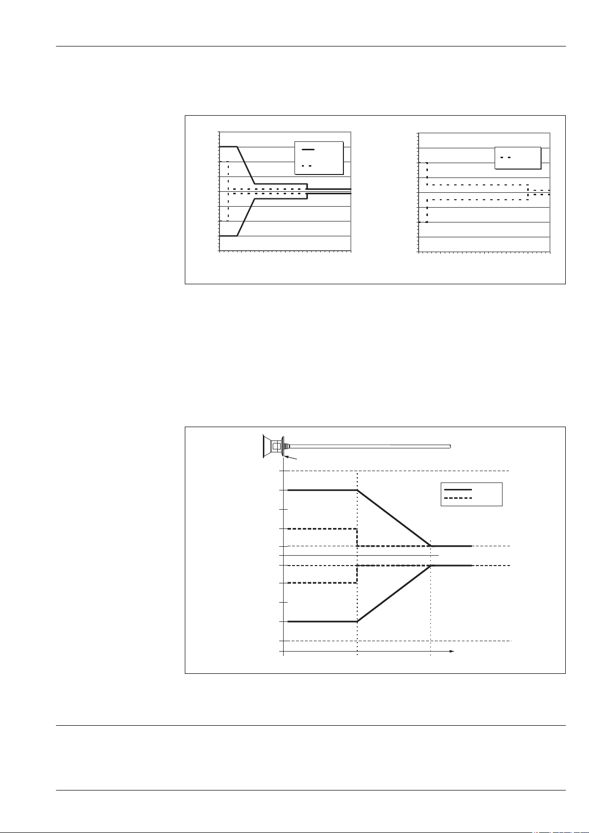
Differing from this, the following measuring error is present in the vicinity of the lower probe
end:
A0016586
1 Rod or coax probe
2 Rope probe
A Distance from probe end
D Sum of non-linearity, non-repeatability and hysteresis
If for rope probes the DC value is less than 7, then measurement is not possible in the area of the straining
weight (0 to 250 mm from end of probe; lower blocking distance).
Differing from this, the following measuring error is present in the vicinity of the upper probe
end (rod/rope only):
Resolution
Endress+Hauser 25
D Sum of non-linearity, non-repeatability and hysteresis
R Reference point of measurement
DC Dielectric constant
digital: 1 mm
•
•
analog: 1 mA
A0015091
Page 26
Levelflex FMP53
A
1 2
C
B
3
Reaction time
Influence of ambient temperature
Suitable mounting position
The reaction time can be parametrized. The following step response times (as per DIN EN 61298-2)
valid if the damping is switched off:
Level measurement
Probe length Sampling rate Step response time
< 10 m (33 ft)
< 40 m (131 ft)
3.6 measurements/second < 0.8 s
³ 2.7 measurements/second
< 1 s
The measurements are carried out in accordance with EN 61298-3
digital (HART, PROFIBUS PA): average TK = 0.6 mm/10 K
•
• analog (current output):
– zero point (4 mA): average TK = 0.02 %/10 K
– span (20 mA): average TK = 0.05 %/10 K
Operating conditions: Installation
1)
are
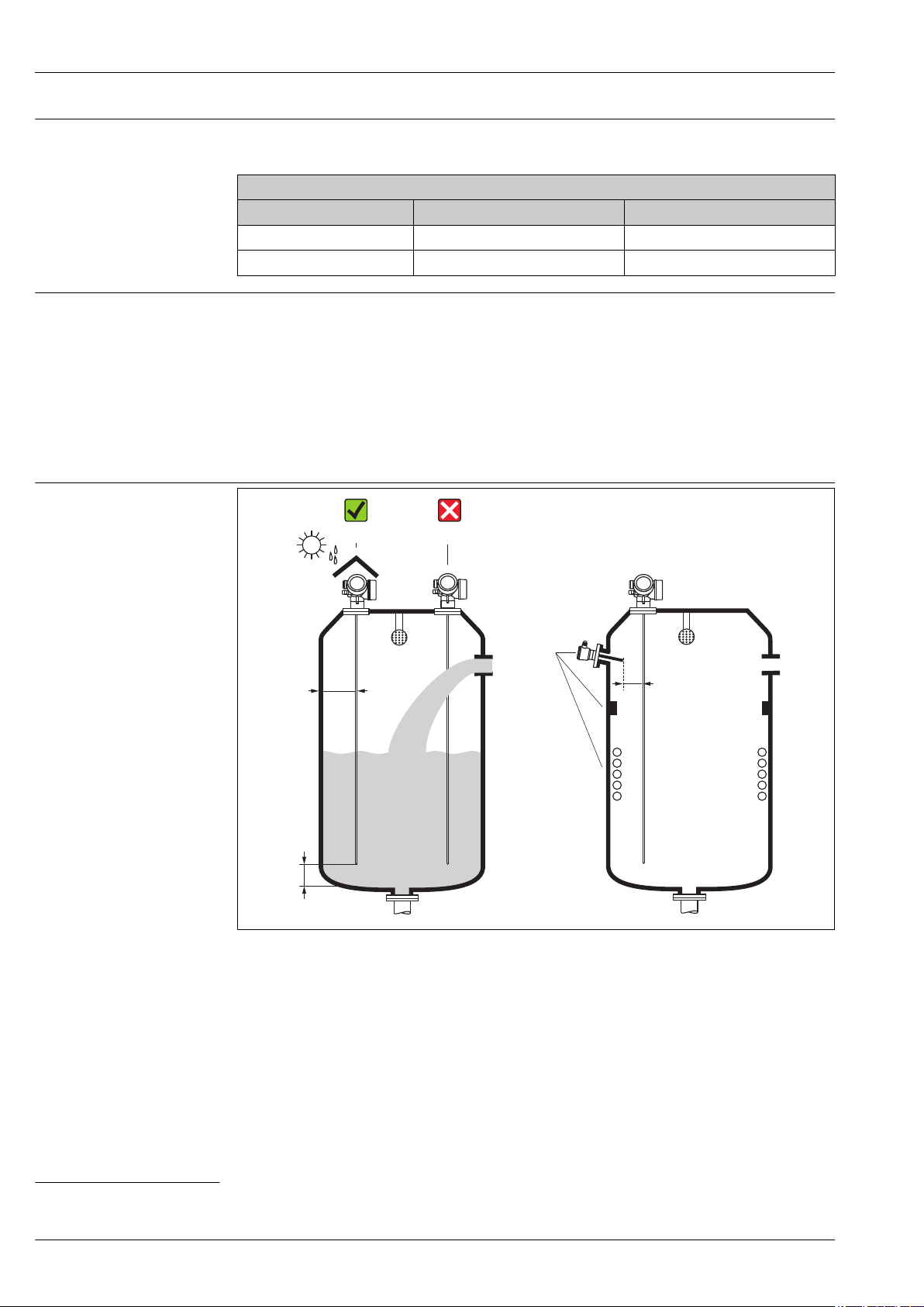
Mounting distances
Distance (A) between wall and rod probe:
•
– for smooth metallic walls: > 50 mm (2")
– for plastic walls: > 300 mm (12") mm to metallic parts outside the vessel
• Distance (B) between rod probe and internal fittings (3) in the vessel: > 300 mm (12")
1) According to DIN EN 61209-2 the response time is the time which passes after a sudden change of the input signal until the output signal for the first time
assumes 90% of the steady-state value.
26 Endress+Hauser
• Distance (C) from end of probe to bottom of the vessel: > 10 mm (0.4 in).
A0014130
Page 27
Levelflex FMP53
3m(9ft)/6m(19ft)
r
min
=50mm(2”)
6Nm
20Nm
Additional conditions
•
When mounting in the open, a weather protection cover (1) may be installed to protect the device against
extreme weather conditions.
• Do not mount the probe in the filling curtain (2).
When mounting the electronics housing into a recess (e.g. in a concrete ceiling), observe a minimum
distance of 100 mm (4 inch) between the cover of the terminal compartment / electronics
compartment and the wall. Otherwise the connection compartment / electronics compartment is not
accessible after installation.
Applications with restricted mounting space
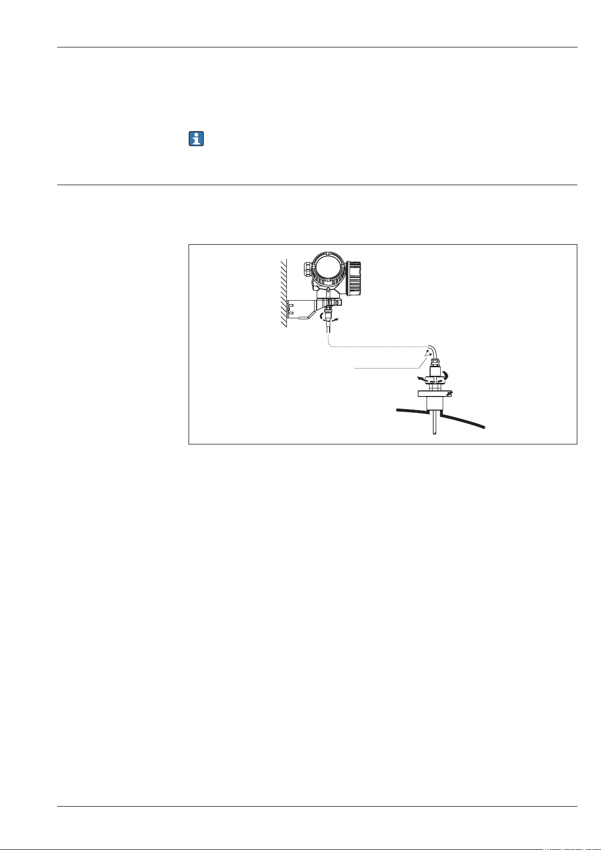
Mounting with remote sensor
The device version with a remote sensor is suited for applications with restricted mounting space. In this
case the electronics housing is mounted at a separate position from which it is easier accessible.
•
Levelflex version (see product structure):
Feature 600 "Probe Design" (® ä 59)
– Option MB "Sensor remote, 3m/9ft cable, detachable+mounting bracket"
– Option MC "Sensor remote, 6m/18ft cable, detachable+mounting bracket"
• On delivery, the connection cable is fixed to the probe.
– Length: 3 m (9 ft) or 6 m (19 ft)
– Minimum bending radius: 100 mm (4 inch)
• A mounting bracket for the electronics housing is supplied with this device version. Mounting options:
– Wall mounting
– Pipe mounting; diameter: 22 to 60 mm (1-1/4 to 2 inch)
A0015103
Endress+Hauser 27
Page 28
Divisible probes
SW10
AF10
Levelflex FMP53
A0014166
Notes on the mechanical load of the probe
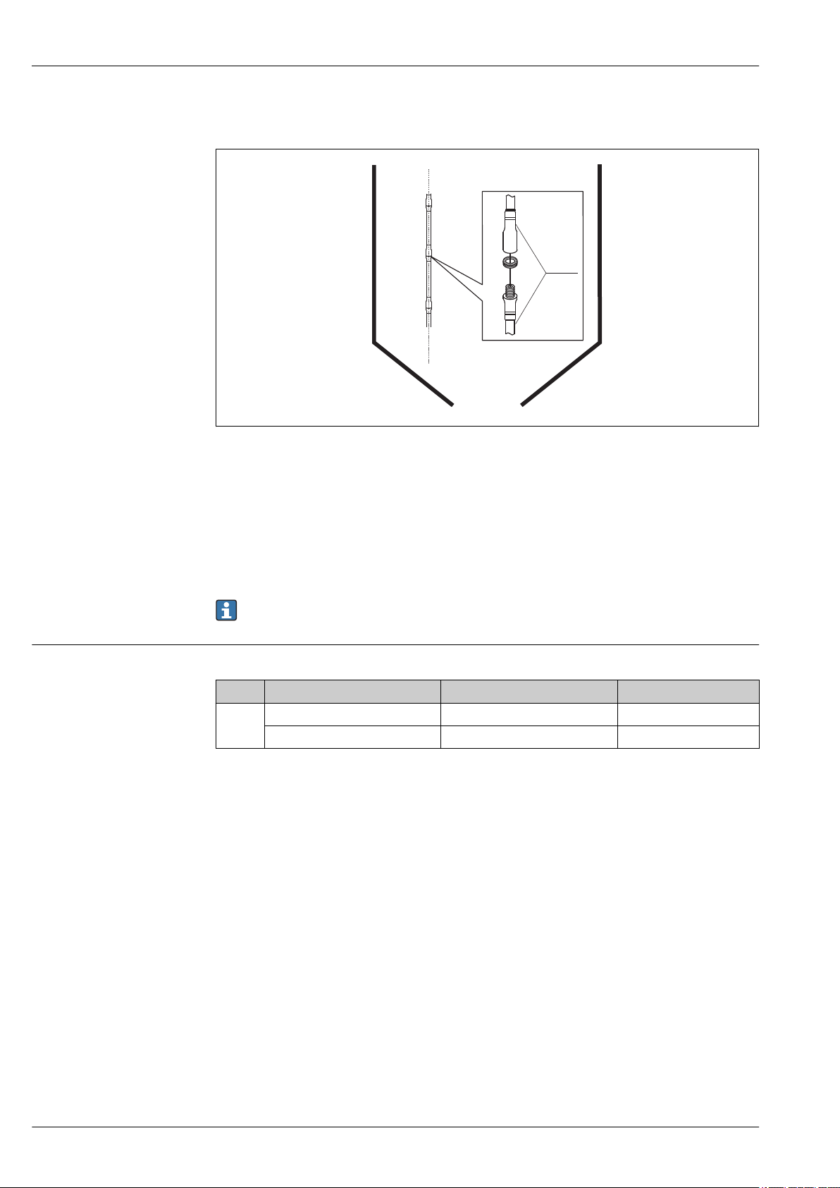
If there is little mounting space (distance to the ceiling), it is advisable to use divisible rod probes (Æ 8 mm).
•
max. probe length 6 m/236 inch
• max. sideways capacity 10 Nm
• probes are separable several times with the lengths:
– 500 mm/20 inch
– 1000 mm/ 40 inch
• torque: 4.5 Nm
• The joints are sealed seamlessly with an O-ring.
In order to avoid damages of the probe surface: Use plumber wrenches with plastic surface to mount
the probe rod.
Bending strength of rod probes
Sensor Feature 060 Probe Bending strength [Nm]
FMP53 DA, DB, EA, EB Rod 8mm (0.31") 316L 10
FA, FB, GA, GB, HA, HB, IA, IB Rod 8mm (0.31") 316L divisible 10
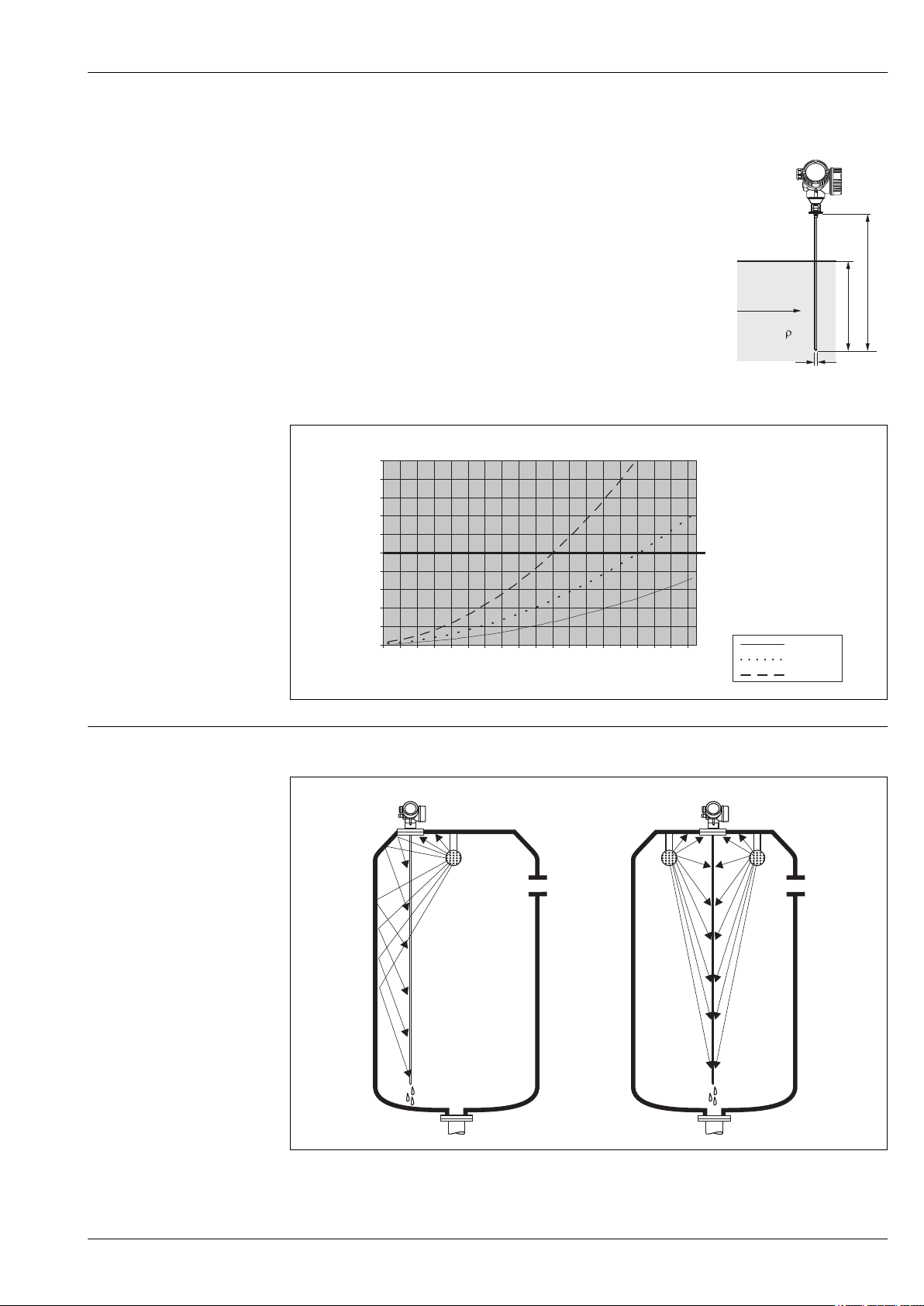
Bending load (torque) through fluid flow
The formula for calculating the bending torque M impacting on the probe:
M = cw × r/2 × v2 × d × L × (LN - 0.5 × L)
with:
cw: Friction factor
r [kg/m3]: Density of the medium
v [m/s]: Velocity of the medium perpendicular to the probe rod
d [m]: Diameter of the probe rod
L [m]: Level
28 Endress+Hauser
Page 29
Levelflex FMP53
v
L
N
L
d
Bendingtorque[M]onrodprobes,diameter8mm(1/3”)
Probelength[ ]inmetersL
N
v=0.5m/s
v=0.7m/s
v=1.0m/s
max.bending torque
0.4 0.8 1.2 1.6 2 2.4 2.8 3.2 3.6 4
0.0
2.0
4.0
6.0
8.0
10.0
12.0
14.0
16.0
18.0
20.0
Bending [Nm]torque
1 2
LN [m]: Probe length
Calculation example
Friction factor c
Density r [kg/m3]
Probe diameter d [m] 0,008
L = L
N
0,9 (on the assumption of a turbulent current - high Reynolds
w
number)
1000 (e.g. water)
(worst case)
A0014175
Special mounting conditions
Endress+Hauser 29
A0014182-EN
Tanks with spray ball for cleaning the probe
A0014131
Page 30
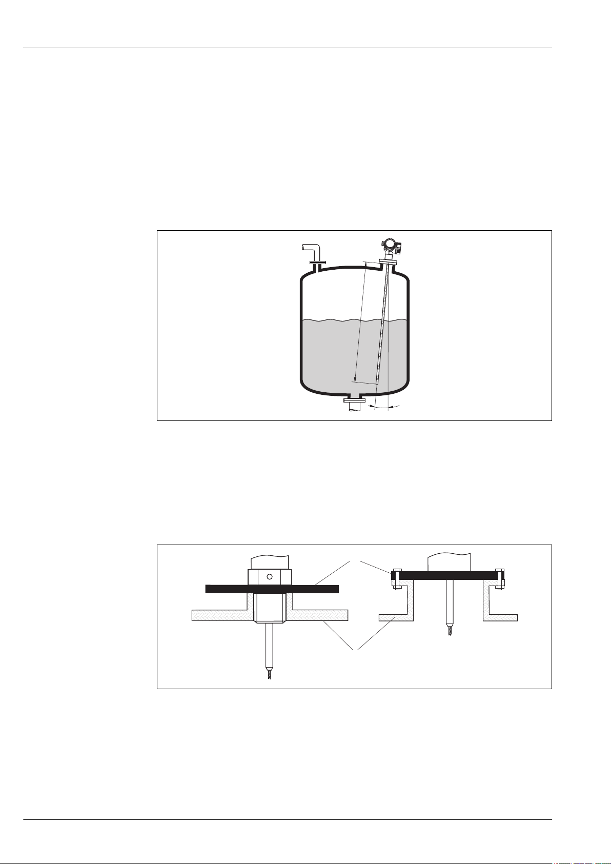
Levelflex FMP53
a
LN
1
2
Installation close to tank wall
By installing the probe close to the tank wall, the cleaning effect is improved in cases where a spray ball is
used. The cleaning jet is deflected against the tank wall and onto the probe. This means that those parts of
the probe are cleaned which would normally not be reached by the spray ball jet. If the probe is positioned
in this way, only one spray ball is needed.
Installation in the center of the tank
If the probe is mounted in the center of the tank, it may be necessary to use a second spray ball. The spray
balls should then be mounted to the left and right of the probe.
Installation at an angle
•
For mechanical reasons, the probe should be installed as vertically as possible.
• With inclined installations the probe length has to be adjusted in dependence to the installation angle.
–
Up to LN = 1 m (3.3 ft): a = 30°
–
Up to LN = 2 m (6.6 ft): a = 10°
–
Up to LN = 4 m (13.1 ft): a = 5°
Non-metallic vessels
1 Non-metallic vessel
2 Metal sheet or metal flange
A0014145
A0012527
To measure, Levelflex with a rod or rope probe needs a metallic surface at the process connection.
Therefore:
Mount a metal sheet with a diameter of at least 200 mm (8") to the probe at the process connection. Its
orientation must be perpendicular to the probe.
30 Endress+Hauser
Page 31
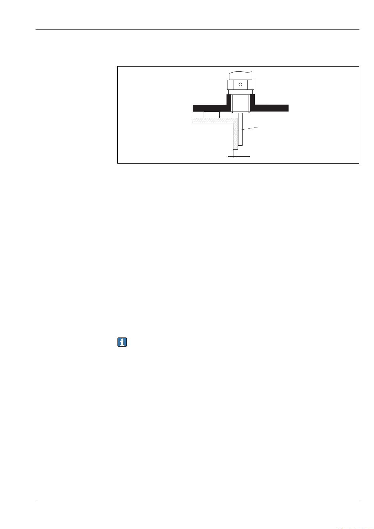
Levelflex FMP53
1
2
a
3
Plastic or glass tanks: Mounting the probe externally at the wall
A0014150
1 Plastic or glass tank
2 Metall sheet with threaded sleeve
3 No free space between tank wall and probe!
Requirements
•
The dielectric constant of the medium must be at least DC > 7.
• The tank wall must be non-conductvie.
• Maximum wall thickness (a):
– Plastic: < 15 mm (0.6")
– Glass: < 10 mm (0.4")
• There may be no metallic reinforcements fixed to the tank.
Mounting conditions:
• The probe must be mounted directly to the tank wall (no open space)
• A plastic half pipe with a diameter of approx. 200 mm (8"), or some other protective unit, must be affixed
externally to the probe to prevent any influences on the measurement.
• If the tank diameter is less than 300 mm (12"):
A metallic grounding sheet must be installed at the opposite side of the tank. The sheet must be
conductively connected to the process connection and cover about the half of the vessel's circumference.
• If the tank diameter exceeds 300 mm (12"):
A metal sheet with a diameter of at least 200 mm (8") must be mounted to the probe at the process
connection. Its orientation must be perpendicular to the probe (see above).
Vessels with heat insulation
If process temperatures are high, the device must be included in normal tank insulation to prevent the
electronics heating up as a result of heat radiation or convection. The insulation may not exceed
beyond the points labeled "MAX" in the drawings.
Endress+Hauser 31
Page 32
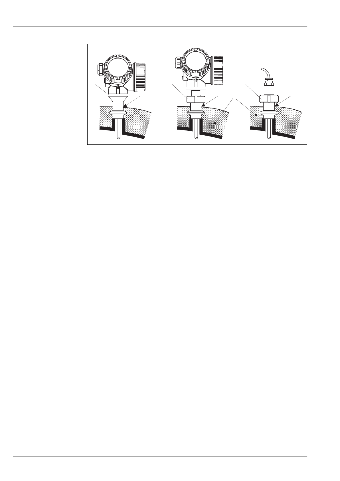
MAXMAX
MAX
1
2
3
4
Hygienic process connections - FMP53
å 8
1 Tank insulation
2 Compact device
3 Compct device, detachable (feature 600)
4 Sensor remote (feature 600)
Levelflex FMP53
A0015809
32 Endress+Hauser
Page 33
Levelflex FMP53
Operating conditions: Environment
Ambient temperature range
Ambient temperature limits
Measuring device
Local display
Connection cable (for
"Probe Design" = "Sensor
remote")
–40 to +80 °C (–40 to +176 °F)
–20 to +70 °C (–4 to +158 °F), the readability of the display may be impaired at
temperatures outside the temperature range.
150 °C (302 °F)
When operating the device in the open with strong sunlight:
• Mount the device in a shady position.
• Avoid direct sunlight, especially in warmer regions.
• Use a weather protection cover (see accessories).
The following diagrams take into account only function requirements. There may be further restrictions
for certified device versions. Please refere to the separate Safety Instructions (® ä 67).
Endress+Hauser 33
Page 34
Levelflex FMP53
[°C] ([°F]) T
a
[°C] ([°F]) T
a
[°C]
([°F])
T
p
[°C]
([°F])
T
p
+150
(+302)
+150
(+302)
+82
(+180)
+79
(+174)
+74
(+165)
-20
(-4)
-20
(-4)
GT20: +68 (+154)
GT20: +64 (+147)
GT19: +53 (+127)
GT19: +53 (+127)
+80 (+176)
GT20: +79 (+174)
GT19: +74 (+165)
-20 (-4)
-20 (-4)
T
a
T
p
4 20 mA HART–
A:
4 20 mA HART–
4 20 mA–
C:
90–253 VAC
K:
10.4–48 VDC
L:
[°C] ([°F]) T
a
[°C]
([°F])
T
p
+150
(+302)
+81
(+178)
-20
(-4)
GT20: +67 (+152)
+81 (+178)
-20 (-4)
PROFIBUS PA
FOUNDATION Fieldbus
G :
1
[°C] ([°F]) T
a
[°C]
([°F])
T
p
+150
(+302)
+79
(+173)
-20
(-4)
GT20: +64 (+147)
+79 (+173)
-20 (-4)
PROFIBUS PA
FOUNDATION Fieldbus
G :
2
Switch output
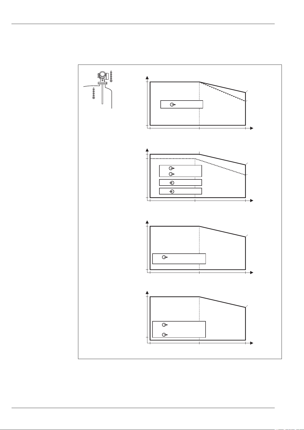
With a temperature (Tp) at the process connection the admissible ambient temperature (Ta) is reduced
according to the following diagram (temperature derating):
Temperature derating for FMP53
GT19 = plastic housing
GT20 = aluminum housing
A = 1 current output
C = 2 current outputs
G1, G2 = PROFIBUS PA
K, L = 4-wire
Ta = ambient temperature
1)
Tp = temperature at the process connection
1) For PROFIBUS PA and FOUNDATION Fieldbus the temperature derating depends on the usage of the switch output.
(G1: switch output not connected; G2: switch output connected).
34 Endress+Hauser
A0013635
Page 35

Levelflex FMP53
Storage temperature
Climate class
Geometric height
Degree of protection
Vibration resistance
Cleaning the probe
–40 to +80 °C (–40 to +176 °F)
DIN EN 60068-2-38 (test Z/AD)
Up to 2 000 m (6 600 ft) above MSL.
Can be expanded to 3 000 m (9 800 ft) above MSL by application of an overvoltage protection, e.g. HAW562
or HAW569.
•
With closed housing tested according to:
– IP68, NEMA6P (24 h at 1.83 m under water surface)
– For plastic housing with transparent cover (display module): IP68 (24 h at 1.00 m under water
surface)
2)
– IP66, NEMA4X
• With open housing: IP20, NEMA1 (also ingress protection of the display)
Degree of protection IP68 NEMA6P applies for M12 PROFIBUS PA plugs only when the PROFIBUS
cable is plugged in and is also rated IP68 NEMA6P.
DIN EN 60068-2-64 / IEC 68-2-64: 20 to 2 000 Hz, 1 (m/s2)2/Hz
Depending on the application, contamination or buildup can accumulate on the probe. A thin, even layer
only influences measurement slightly. Thick layers can dampen the signal and then reduce the measuring
range. Severe, uneven buildup, adhesion e.g. through crystallization, can lead to incorrect measurement. In
this case, we recommend that you use a non-contact measuring principle, or check the probe regularly for
soiling.
Electromagnetic compatibility (EMC)
Electromagnetic compatibility to all relevant requirements of the EN 61326- series and NAMUR
recommendation EMC (NE21). For details see declaration of conformity.
3)
. If only the analogue signal is
used, unshielded interconnection lines are sufficient for the installation. In case of using the digital signal
(HART/ PA/ FF) use shielded interconnection lines.
Use a shielded cable when working with a digital communications signal.
Max. fluctuations during EMC- tests: < 0.5 % of the span.
When installing the probes in metal and concrete tanks and when using a coax probe:
• Interference emission to EN 61326 - x series, electrical equipment Class B.
• Interference immunity to EN 61326 - x series, requirements for industrial areas and NAMUR
Recommendation NE 21 (EMC)
The measured value can be affected by strong electromagnetic fields when installing rod and rope probes
without a shielding/metallic wall, e.g. in plastic and wooden silos.
• Interference emission to EN 61326 - x series, electrical equipment Class A.
• Interference Immunity: the measured value can be affected by strong electromagnetic fields.
2) This restriction is valid if the following options of the product structure have been selected at the same time: 030("Display, Operation") = C("SD02") or
E("SD03"); 040("Housing") = A("GT19").
3)
Can be downloaded from www.endress.com.
Endress+Hauser 35
Page 36
Operating conditions: Process
1
4
3
1
5
4
2
3
Levelflex FMP53
Process temperature range
Process pressure limits
Materials in contact with process
The maximum permitted temperature at the process connection is determined by the O-ring version
ordered:
Device O-ring material Process temperature Approval
FMP53 EPDM (Freudenberg 70 EPDM 291) –20 to +130 °C (–4 to +266 °F) FDA
3-A
1)
USP Cl. VI
FFKM (Kalrez 6221) –20 to +150 °C (–4 to +302 °F) FDA
FKM (PPE V70SW) –10 to +150 °C (+10 to +302 °F)
3)
3-A
USP Cl. VI
1) Tested acc. to 3-A Sanitary Standard 18-03, Class II
Tested acc. to USP <88> Class VI - 121°C
2)
3) Tested acc. to 3-A Sanitary Standard 18-03, Class I
4) Tested acc. to USP <88> Class VI - 121°C
Device Process pressure
FMP53 –1 to 16 bar (–14.5 to 232 psi)
This range may be reduced by the selected process connection. The pressure rating (PN) specified on
the flanges refers to a reference temperature of 20 °C. Pay attention to pressure-temperature
dependencies.
Further material specifications (® ä 44)
2)
4)
Levelflex FMP53
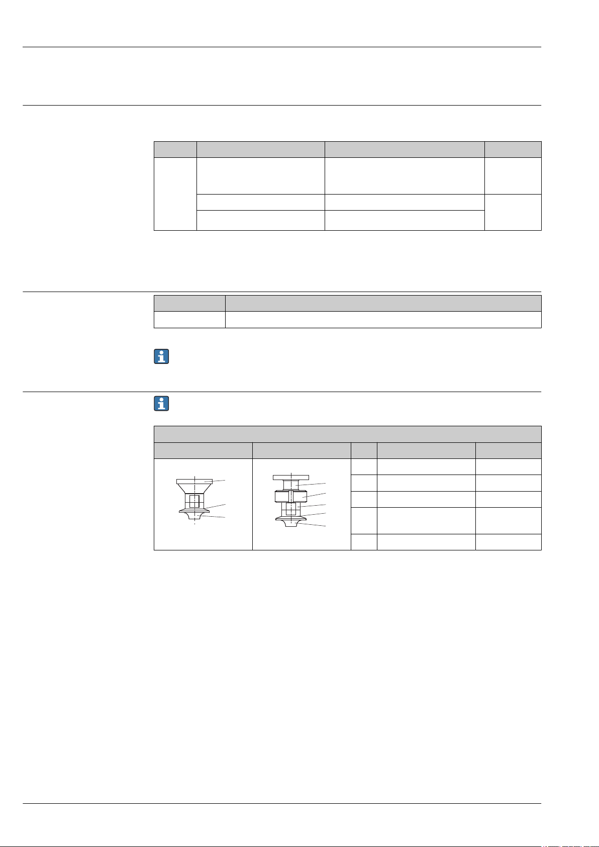
Sensor not detachable Sensor detachable No. Material Approval
1 304 (1.4301) —
2 304 (1.4301) —
3 316L (1.4435) —
4 Ketron PEEK LSG FDA, 3A,
A0013904
A0013903
USP Cl. VI
5 304L (1.4307) —
36 Endress+Hauser
Page 37
Levelflex FMP53
1
1
1
1
2
2
1
1
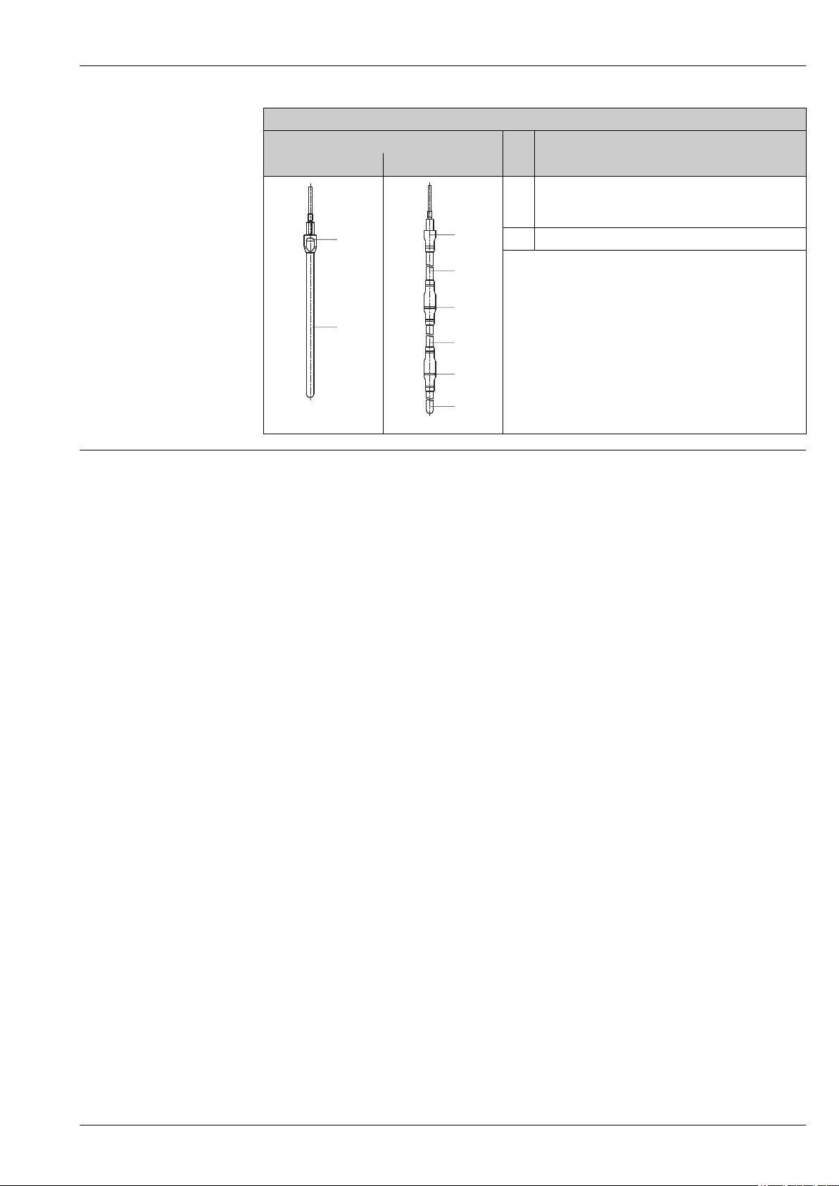
Rod probe
Æ 8 mm (1/3") Æ 8 mm (1/3") divisible
A0013872
Levelflex FMP53
No. Material
1 316L (1.4435)
2 O-ring (see sensor)
A0013873
•
0.76 mm (30 min) mechanically polished
•
0.38 mm (15 min) electro-polished
Dielectric constant (DC)
Rod probe: DC (er) ³ 1.6
Endress+Hauser 37
Page 38
Mechanical construction
163(6.42)
134.5(5.3)
ø106(ø4.17)
78(3.07) 90(3.54)
ø106(ø4.17)
R100
144(5.67)
141.5(5.57)
117.1(4.61)
ø111(ø4.37)-1°
ø108.5(ø4.27)
78(3.07)
90(3.54)
ø103.5(ø4.07)
R100
Levelflex FMP53
Design, dimensions
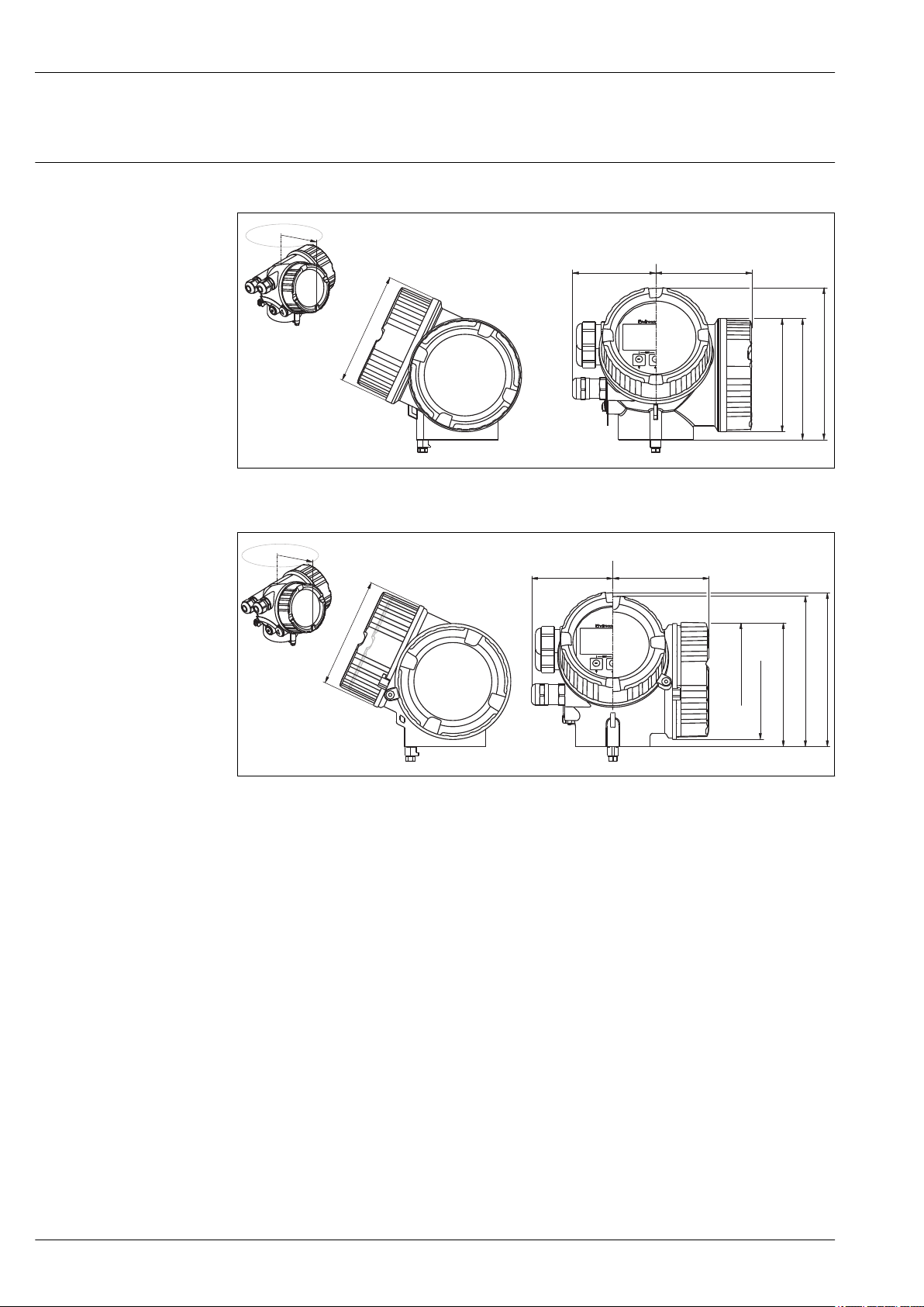
Dimensions of the electronics housing
Housing GT19 (Plastics PBT); Dimensions in mm (in)
å 9
A0015133
Housing GT20 (Alu coated); Dimensions in mm (in)
å 10
A0015134
38 Endress+Hauser
Page 39
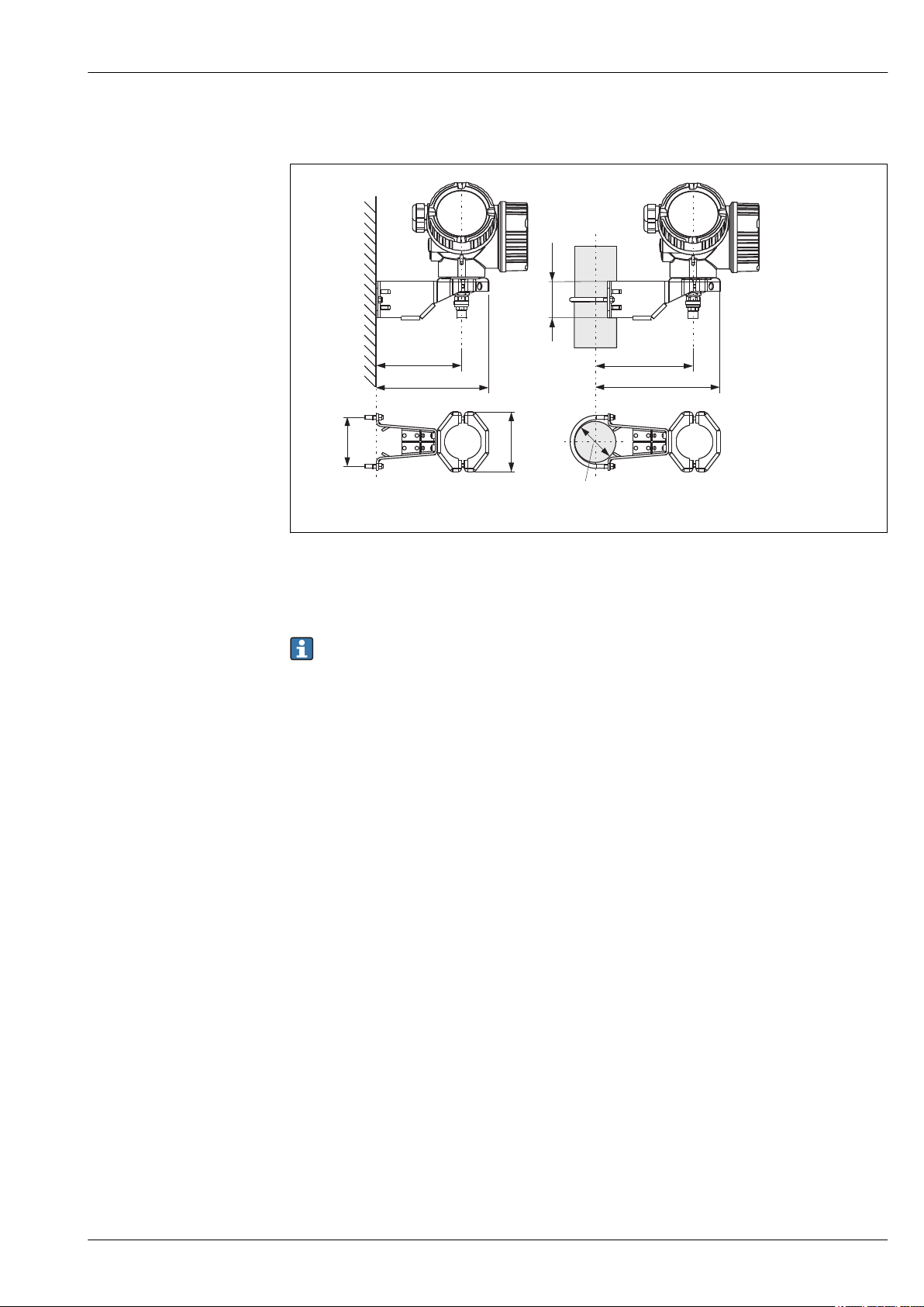
Levelflex FMP53
122(4.8)
52
(2)
86
(3.4)
70
(2.8)
140(5.5)
158(6.2)
175(6.9)
A B
mm(inch)
Ø42...60
(1-1/4...2)
Dimensions of the mounting bracket
Mounting bracket for the electronics housing
å 11
A Wall mounting
B Pipe mounting
For the "Sensor remote" device version (see feature 060 of the product structure), the mounting
bracket is part of the delivery. If required, it can also be ordered as an accessory (order code
71102216).
A0014793
Endress+Hauser 39
Page 40
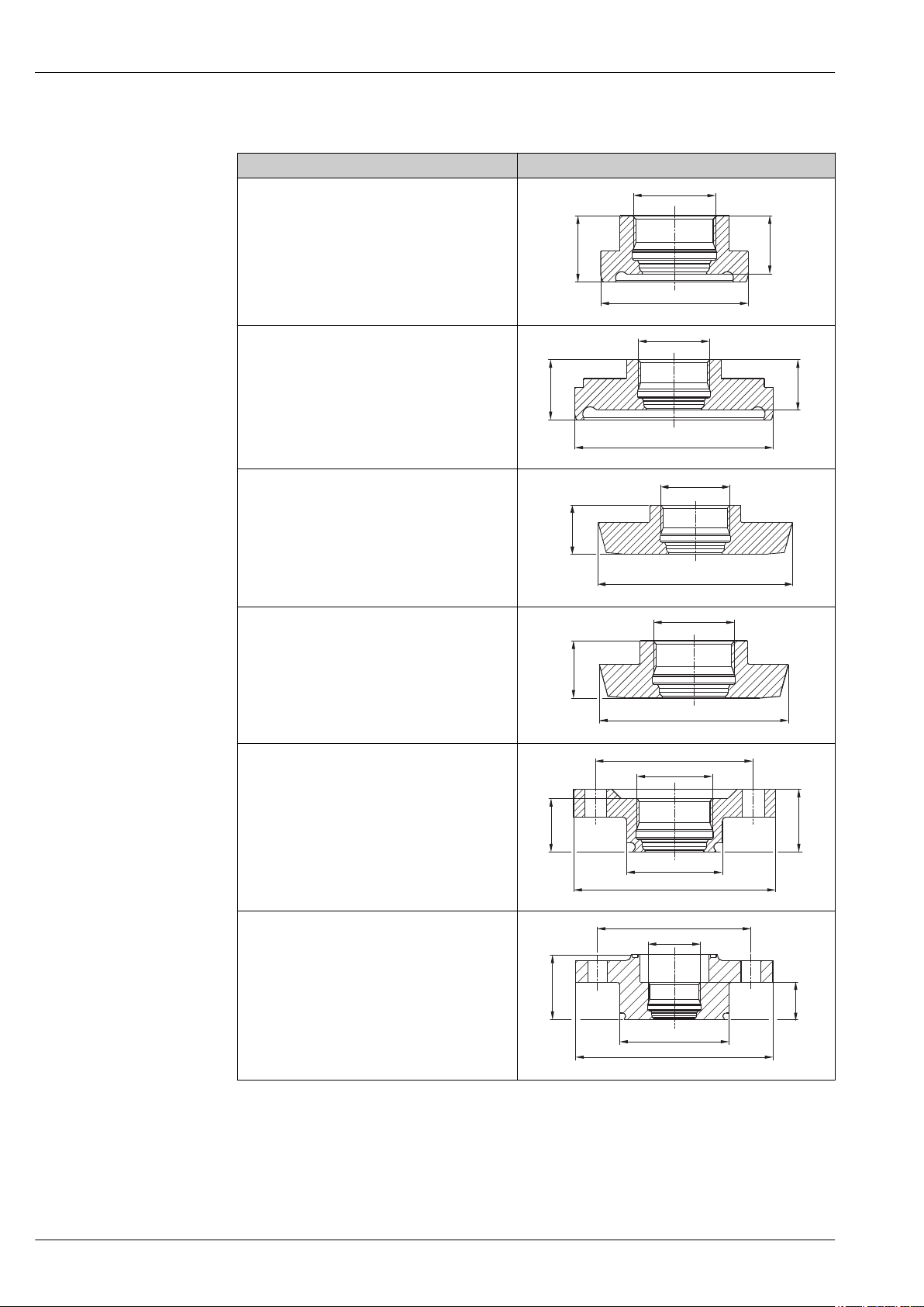
FMP53: Dimensions of process connection
19.3
(0.76)
17
(0.67)
ø42.9(ø1.69)
M24x1.5
20.4
(0.8)
17
(0.67)
ø66.9(ø2.63)
M24x1.5
17
(0.67)
ø68 (ø2.68)
M24x1.5
17
(0.67)
ø56(ø2.2)
M24x1.5
17
(0.67)
20
(0.79)
ø56(ø2.2)
ø30.4(ø1.2)
M24x1.5
ø50(ø1.97)
29.6
(1.17)
17
(0.67)
ø90(ø3.54)
ø49.9(ø1.96)
ø70(ø2.76)
M24x1.5
Version Dimensions [mm (inch)]
MAJ
DIN11864-1 A DN25 tube DIN11866-A, 316L
MDJ
DIN11864-1 A DN50 tube DIN11866-A, 316L
MOJ
DIN11851 DN50 PN40 cap-nut, 316L
Levelflex FMP53
A0012763
A0012764
MQJ
DIN11851 DN40 PN40 cap-nut, 316L
S1J
NEUMO BioControl D25 PN16, 316L
S4J
NEUMO BioControl D50 PN16, 316L
(Not available with Probe Design "Sensor compact",
feature 600, option MA)
A0012766
A0012765
A0012767
40 Endress+Hauser
A0012768
Page 41
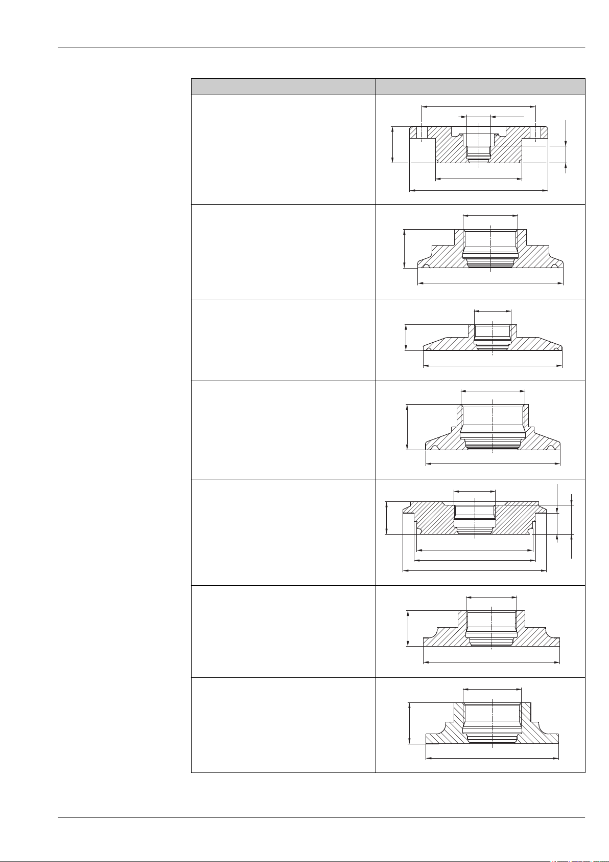
Levelflex FMP53
37
(1.46)
17
(0.67)
ø140(ø5.51)
ø87.4(ø3.44)
ø115(ø4.53)
M24x1.5
17
(0.67)
ø63.9(ø2.52)
M24x1.5
17
(0.67)
ø90.9(ø3.58)
M24x1.5
17
(0.67)
ø50.4(ø1.98)
M24x1.5
19
(0.75)
12.3
(0.48)
17
(0.67)
ø84(ø3.31)
ø71(ø2.8)
ø68(ø2.68)
M24x1.5
17
(0.67)
ø65( 2.56)ø
M24x1.5
17
(0.67)
ø54.85(ø2.16)
M24x1.5
Version Dimensions [mm (inch)]
S6J
NEUMO BioControl D80 PN16, 316L
(Not available with Probe Design "Sensor compact",
feature 600, option MA)
A0012769
TDJ
Tri-Clamp ISO2852 DN40-51 (2"), 316L
A0012770
TFJ
Tri-Clamp ISO2852 DN70-76.1 (3"), 316L
TOJ
Tri-Clamp ISO2852 DN25-38 (1...1-1/2"), 316L
TSJ
Varivent N pipe DN40-162 PN16, 316L
TXJ
SMS 2" PN25, 316L
A0012771
A0012772
A0012773
A0012774
T7J
SMS 1-1/2" PN25, 316L
Endress+Hauser 41
A0012775
Page 42
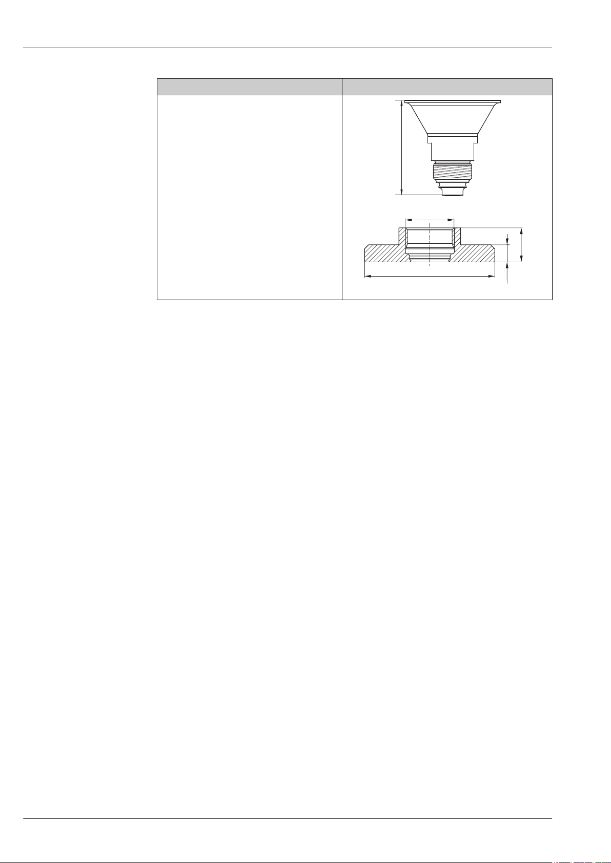
Version Dimensions [mm (inch)]
73(2.87)
ø65 (ø )2.7
M24 x 1.5
17
(0.67)
8.5
(0.33)
U1J
Thread M24, 316L
For the process connection U1J you need the following
weld-in adapter:
Order code: 71041381
P
= 16 bar (232 psi)
max
Material: 316L (1.4435)
Levelflex FMP53
A0014608
A0012776
42 Endress+Hauser
Page 43
Levelflex FMP53
D
G
H
A
E
F
C
B
98.7
(3.89)
73 (2.87)
LN
53.7
(2.11)
ø53.5
(ø2.11)
ø59.35
(ø2.34)
SW27
AF27
SW27
AF27
SW27
AF27
ø8
(ø0.31)
ø8
(ø0.31)
ø13
(ø0.51)
ø13
(ø0.51)
SW10
AF10
SW10
AF10
SW10
AF10
SW10
AF10
ø59.35
(ø2.34)
mm (in)
R
R
122
(4.8)
52
(2.05)
50
(1.97)
46
(1.81)
ø25 (ø0.98)
ø53.5
(ø2.11)
ø59.4
(ø2.34)
101.6 (4)
46
(1.81)
ø25 (ø0.98)
ø53.5
(ø2.11)
127.3 (5.01)
4.4 (0.17)
2
(0.08)
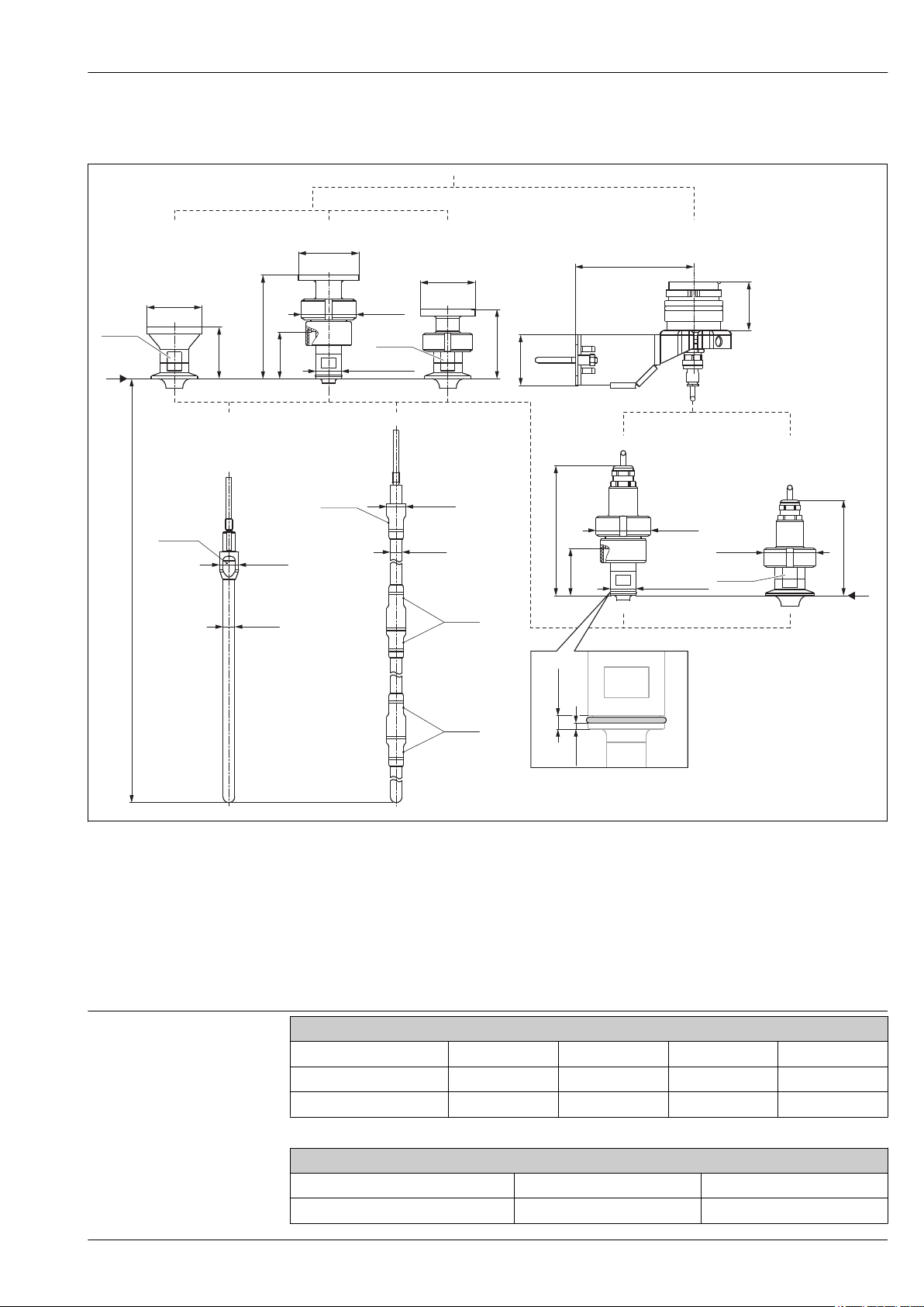
FMP53: Dimensions of probe
Tolerance of probe length
A Sensor compact (No option selected in feature 600)
B Sensor compact, detachable, with Ingold fitting
C Sensor compact, detachable (Feature 600)
D Mounting bracket for probe design "Sensor remote" (Feature 600)
E Rod probe 8mm or 1/3" (Feature 060)
F Rod probe 8mm or 1/3", 20in or 40in divisible (Feature 060)
G Ingold fitting for probe design "Sensor remote"
H Other process connections for probe design "Sensor remote"
LN Length of probe
R Reference point of the measurement
Over [m (ft)] — 1 (3,3) 3 (9,8) 6 (20)
Up to [m (ft)] 1 (3,3) 3 (9,8) 6 (20) —
Admissible tolerance [mm (in)] -10 (-0,39) -20 (-0,79) -30 (-1,18) -40 (-1,57)
Rod length <1 (<3,3) 1...<4 (3,3...<13)
Admissible tolerance [mm (in)] +0 / -3 (-0,12) +0 / -5 (-0,2)
Rope probes
Rod probes
Endress+Hauser 43
A0012762
Page 44
Levelflex FMP53
2.1 1
2.2 5
678
934
Weight
Materials
Housing
Part Weight
Housing GT19 - plastic approx. 1.2 kg
Housing GT20 - aluminium approx. 1.9 kg
FMP53
Part Weight Part Weight
Sensor approx. 1.2 kg Rod probe 8 mm approx. 0.4 kg/m probe length
Further material specifications
•
Materials in contact with process
•
Ordering information (® ä 56)
•
Accessories materials (® ä 62)
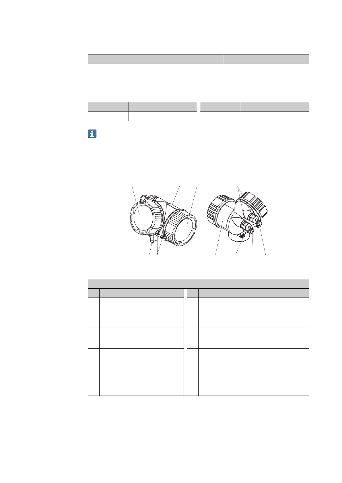
Housing
No. Part: material No. Part: material
1 Housing: PBT 5 Cable entry
2.1 Cover of the electronics compartment
• Cover: PA
• Cover seal: EPDM
2.2 Cover of the terminal compartment
• Cover: PBT
• Cover seal: EPDM
4 Turn housing
• Screw: A4-70
• Clamp: 316L (1.4404)
Housing GT19 - plastic
•
Sealing: EMPB
• Cable gland: polyamide (PA), nickel-plated brass (CuZn)
• Adapter: 316L (1.4435)
6 Dummy plug: PBT
7 Pressure relief stopper: nickel-plated brass (CuZn)
8 Ground terminal
• Screw: A2
• Spring washer: A4
• Clamp: 304 (1.4301)
• Holder: 304 (1.4301)
9 Identification
Nameplate: sticker
A0013788
44 Endress+Hauser
Page 45
Levelflex FMP53
10
1
1
12
12
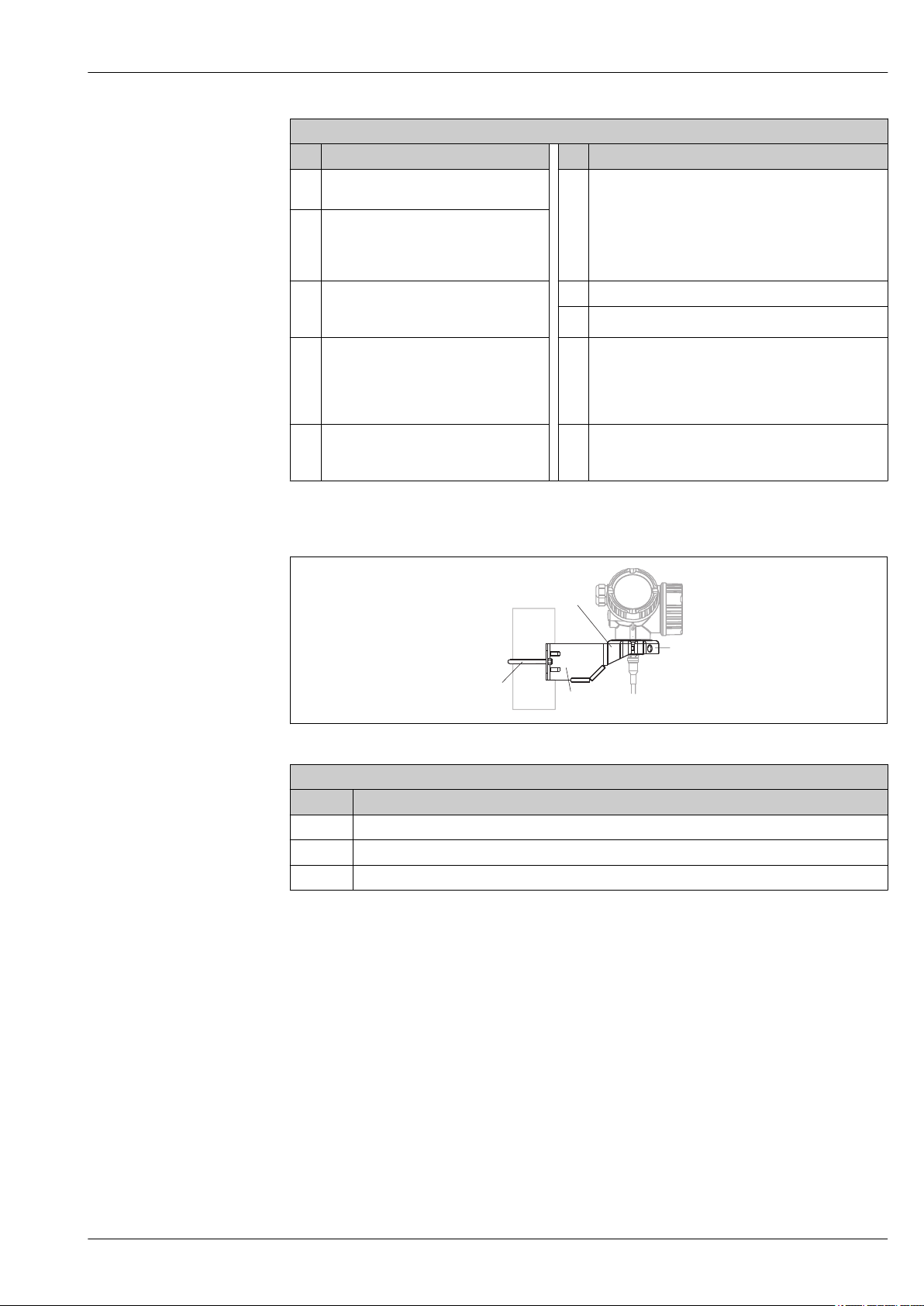
Housing GT20 - die-cast aluminum, powder-coated, seawater-resistant
No. Part: material No. Part: material
1 Housing: AlSi10Mg(<0.1% Cu)
Coating: polyester
2.1 Cover of the electronics compartment
• Cover: AlSi10Mg(<0.1% Cu)
5 Cable entry
Sealing: EMPB
•
• Cable gland: polyamide (PA), nickel-plated brass (CuZn)
• Adapter: 316L (1.4435)
• Window: glass
• Cover seal: EPDM
2.2 Cover of the terminal compartment
• Cover: AlSi10Mg(<0.1% Cu)
• Cover seal: EPDM
3 Cover lock
• Screw: A4
• Clamp: 316L (1.4404)
6 Dummy plug: nickel-plated brass (CuZn)
7 Pressure relief stopper: nickel-plated brass (CuZn)
8 Ground terminal
• Screw: A2
• Spring washer: A2
• Clamp: 304 (1.4301)
• Holder: 304 (1.4301)
4 Turn housing
• Screw: A4-70
9 Identification
Nameplate: sticker
• Clamp: 316L (1.4404)
Mounting bracket
Mounting bracket for version "Sensor remote"
No. Part: material
10 Bracket: AISI 304 (1.4301), AISI 304L (1.4306)
11 Screw and nuts: A2-70
12 Half-shells: AISI 304L (1.4306)
A0015143
Endress+Hauser 45
Page 46
Weather protection cover
1
2.1
3.1
3.2
4
5.1
5.2
4
6
2.2
2.2
2.1
2.1
2.2
2
1
Levelflex FMP53
A0015473
Overview
Operating options
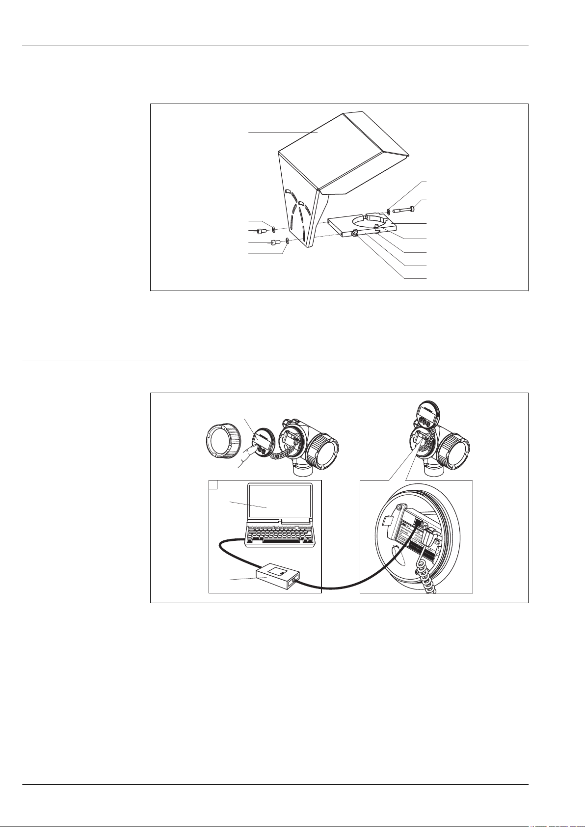
On-site operation
On-site operation options
å 12
1 Display module SD02, push buttons; cover must be open for operation
2 Operating options via CDI interface (= Endress+Hauser Common Data Interface)
2.1 Computer with operating tool (FieldCare)
2.2 Commubox FXA291, connected to the CDI interface of the device
A0014125
46 Endress+Hauser
Page 47
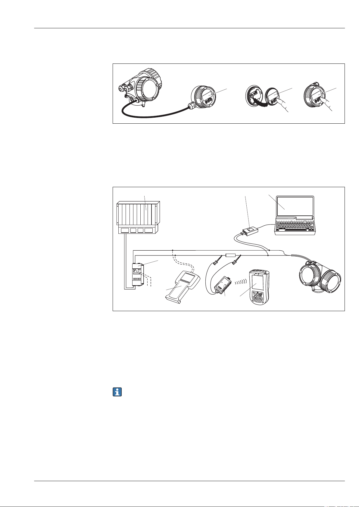
Levelflex FMP53
3
2
1
ENDRESS + HAUSER
RMA 422
1
7
4
8
2
6 5
3
Operation with remote display and operating module FHX50
A0013137
FHX50 operating options
å 13
1 Housing of the remote display and operating module FHX50
2 Display and operating module SD02, push buttons; cover must be removed
3 Display and operating module SD03, optical keys; can be operated through the glass of the cover (in preparation)
Remote operation via HART
A0012624
Remote operating options via HART
å 14
1 PLC
2 Commubox FXA191 (RS232) or FXA195 (USB)
3 Computer with operating tool (e.g. FieldCare, AMS, Simatic PDM)
4 Handheld terminal DXR375/FC375
5 Field Xpert
6 VIATOR Bluetooth modem with connection cable
7 Transmitter supply unit RMA422 or RN221N (communication resistor included)
8 Connection for Commubox FXA191, FXA195 or handheld terminal DXR375/FC375
In hazardous areas only use certified operating tools!
System integration via PROFIBUS PA
A maximum of 32 devices (8 if mounted in an explosion hazardous location Ex ia IIC according to FISCOmodel) can be connected to the bus. The segment coupler provides the operating voltage to the bus. Both
on-site as well as remote operation are possible.
Endress+Hauser 47
Page 48
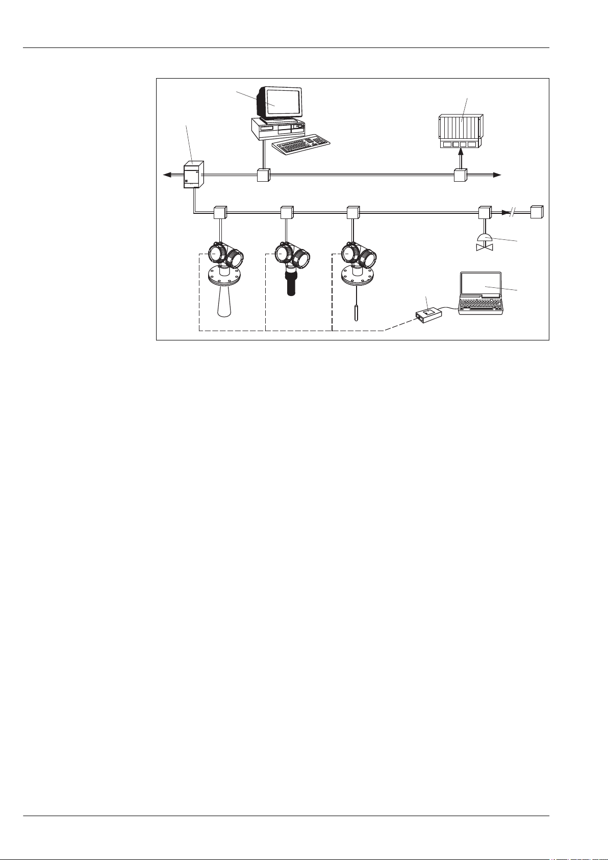
Levelflex FMP53
ENDRESS + HAUSER
Micropilot
Prosonic
Levelflex
T
PROFIBUSDP
PROFIBUSPA
1
6
2
3
4
5
A0011275
The complete measuring system consists of devices and:
å 15
1 Segment coupler
2 Computer with Profiboard/Proficard and operating tool (FieldCare)
3 PLC (programmable logic controller)
4 More functions (valves etc.)
5 Computer with operating tool (FieldCare)
6 Commubox FXA291 (CDI interface)
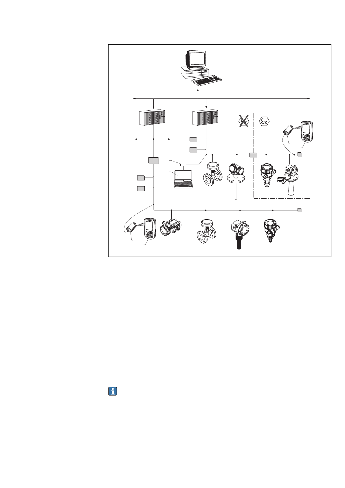
System integration via FOUNDATION Fieldbus
The following diagram shows two typical examples of a FOUNDATION Fieldbus network with the
associated components.
48 Endress+Hauser
Page 49
Levelflex FMP53
FF-H1
FF-H1
BT
BT
PS
3
4
PS
BT
SB
BT
FF-HSE
IN
LD
ENDRESS + HAUSER
E
+–
%
1
1
2
2
A0017188
FOUNDATION Fieldbus system architecture with associated components
å 16
IN Industrial network
FF-
High Speed Ethernet
HSE
FF-H1FOUNDATION Fieldbus-H1
LD Linking Device FF-HSE/FF-H1
PS Bus Power Supply
SB Safety Barrier
BT Bus Terminator
1 FFblue Bluetooth modem
2 Field Xpert SFX100
3 FieldCare
4 NI-FF interface card
The system can be connected in the following ways:
•
A linking device makes the connection to higher-order fieldbus levels (e.g. High Speed Ethernet (HSE))
possible.
• An FF-H1 connecting card is needed for direct connection to a process control system.
Further information on FOUNDATION Fieldbus can be found in Operating Instructions BA00013S
"FOUNDATION Fieldbus Overview, Installation and Commissioning Guidelines", the FOUNDATION
Fieldbus Specification or on the Internet at "http://www. fieldbus.org".
Endress+Hauser 49
Page 50
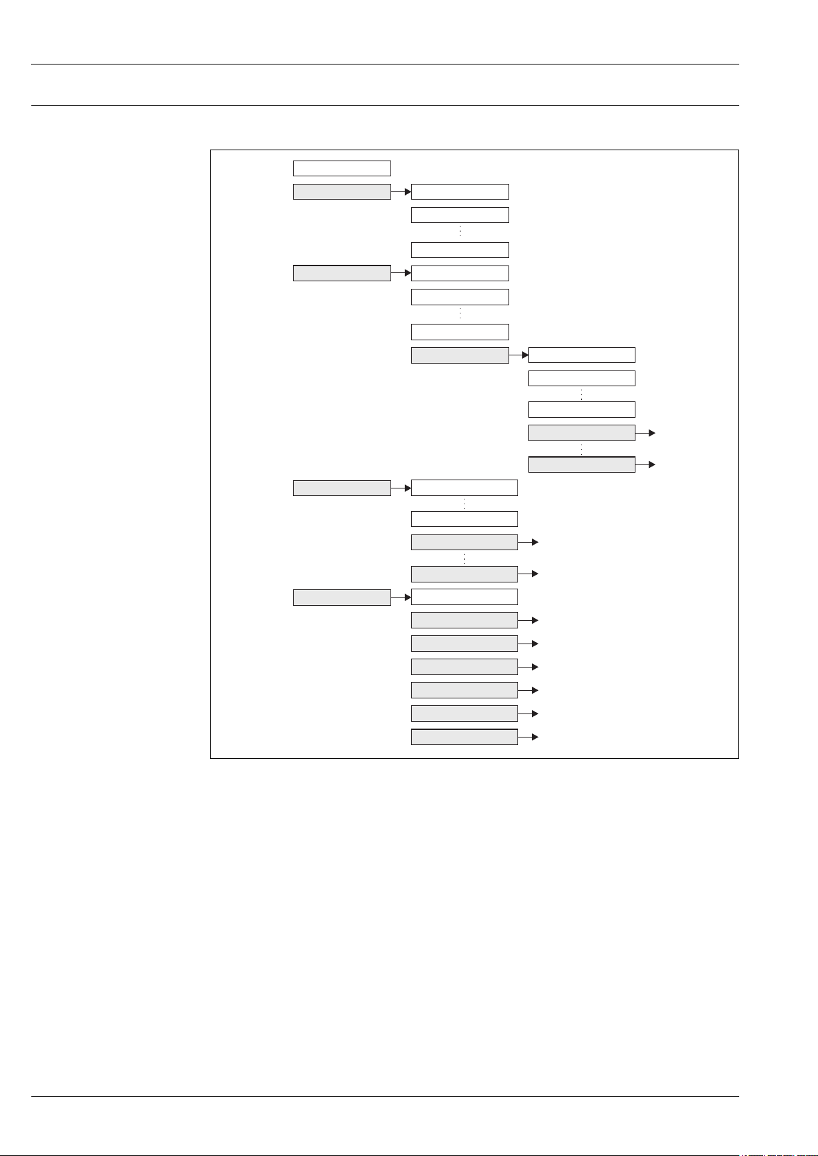
The operating menu Structure
Language
Display/operation Parameter1
Parameter2
ParameterN
Setup
Setupparameter1
Setupparameter2
SetupparameterN
Advancedsetup
Enteraccesscode
Parameter1
ParameterN
Submenu1
SubmenuN
Diagnostics
Parameter1
ParameterN
Submenu1
SubmenuN
Expert
Directaccess
System
Sensor
Output
Communication
Application
Diagnostics
Levelflex FMP53
Basic structure of the operating menu; gray: submenus; white: parameters
å 17
A0011407-EN
50 Endress+Hauser
Page 51

Levelflex FMP53
Submenus and user roles
The submenus are designed for different user roles. A user role is defined by typical tasks within the lifecycle
of the device.
User role Typical tasks Submenu Content/Meaning
Operator Tasks in the ongoing process:
Maintenance Commissioning:
Expert Tasks which require detailed knowledge about the
Configuration of the display.
•
• Reading measuring values.
• Configuration of the measurement.
• Configuration of the measured value processing (scaling,
linearization, limit detection etc.).
• Configuration of the measured value output (analog and
digital communication interface).
Error handling "Diagnostics" Contains all parameters needed to detect and analyze
instrument:
• Commissioning of measurements under demanding
conditions.
• Optimization of the measurement under demanding
conditions.
• Detailed configuration of the communication interface.
• Error diagnosis in diffcult cases.
"Language" Defines the operating language.
"Display/Operation" Contains all parameters which are needed during the
ongoing process:
Configuration of the display (display values, display format,
display contrast ...).
"Setup" Contains all commissioning parameters:
"Expert" Contains all parameters of the device (including those
Setup parameters
•
When all these parameters have been assigned
appropriate values, the measured should be completely
configured in a standard application.
"Advanced setup" submenu
•
Contains further submenus and parameters:
– to adapt the device to special measuring conditions.
– to process the measured value (scaling, linearization).
– to configure the signal output.
operational errors.
Diagnostics list
•
Contains up to 5 currently active error messages.
Event logbook
•
Contains the 10 last messages (which are no longer
active).
"Device info" submenu
•
Contains information needed to identify the device.
"Measured values" submenu
•
Contains all current measured values.
"Simulation" submenu
•
Used to simulate measured values or output values.
which are already contained in one of the above
submenus). This menu is organized according to the
function blocks of the device:
"System" submenu
•
Contains all general device parameters which do not
affect the measurement or the communication interface.
"Sensor" submenu
•
Contains all parameters needed to configure the
measurement.
"Output" submenu
•
Contains all parameters needed to configure the current
output.
Contains all parameters needed to configure the switch
output (PFS)
"Communication" submenu
•
Contains all parameters needed to configure the digital
communication interface.
"Diagnostics" submenu
•
Contains all parameters needed to detect and analyze
operational errors.
Locking the menu
Locking the menu via the locking switch (hardware locking)
The complete operating menu can be locked by the locking switch below the display and operating module.
In the locked state most parameter values can be read but not changed.
Endress+Hauser 51
Page 52
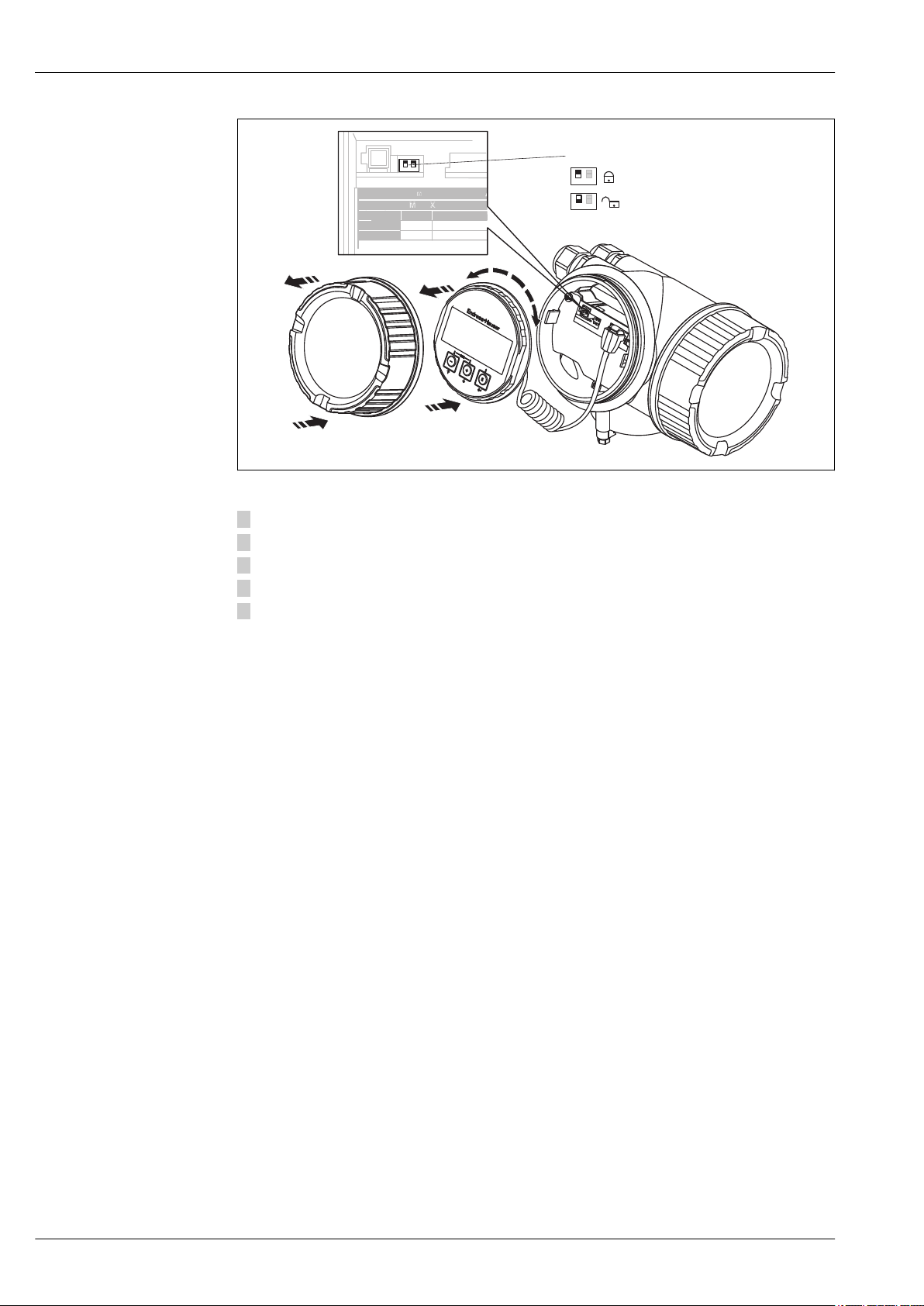
Levelflex FMP53
1
2
5
4
3
(B)
(A)
CDI
Sparepart:FMP52X-AB
WP SIM
SW
exworks
SWupdate#1
SWupdate#2
02.01.03Dev_R
DISPL
A0013132
1. Unscrew the lid from the compartment for the display and operating module.
2. Slightly turn the display and operating module to remove it from the compartment.
3. Set the locking switch (WP: Write Protection) into the desired position. (A): unlocked; (B): locked.
4. Attach the display and operating module in the desired orientation until it closes with a snap.
5. Screw the lid onto the compartment.
Locking the menu via parameter settings (software locking)
52 Endress+Hauser
Page 53
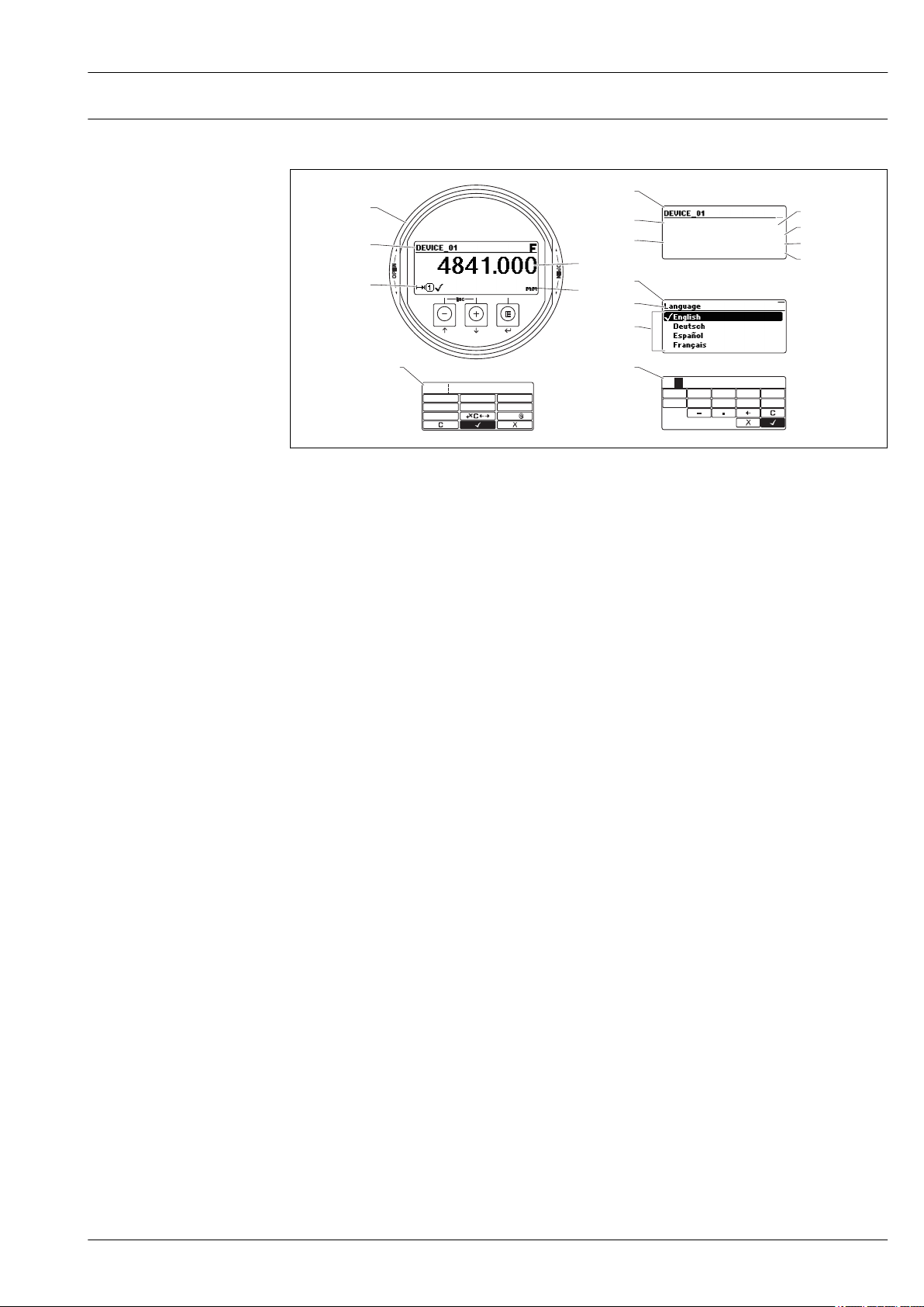
Levelflex FMP53
3.1
3.2
2.1
2.2
2.4
2.5
1.1
1.2
1.3
1.4
2.3
2.6
1
2
3
45
ESC
OPEN
OPEN
E
ABC_
DEFG
User
HIJK
LMNO
PQRS
TUVW
XYZ
Aa1
3
4
0
1 2
9
5
6
8
7
20
Display and operating module Display appearance
Appearance of the display and operation module for on-site operation
å 18
1 Measured value display (1 value max. size)
1.1 Header containing tag and error symbol (if an error is active)
1.2 Measured value symbols
1.3 Measured value
1.4 Unit
2 Measured value display (1 bargraph + 1 value)
2.1 Bargraph for measured value 1
2.2 Measured value 1 (including unit)
2.3 Measured value symbols for measured value 1
2.4 Measured value 2
2.5 Unit for measured value 2
2.6 Measured value symbols for measured value 2
3 Representation of a parameter (here: a parameter with selection list)
3.1 Header containing parameter name and error symbol (if an error is active)
3.2
Selection list; Â marks the current parameter value.
4 Input matrix for numbers
5 Input matrix for alphanumeric and special characters
A0012635
Endress+Hauser 53
Page 54
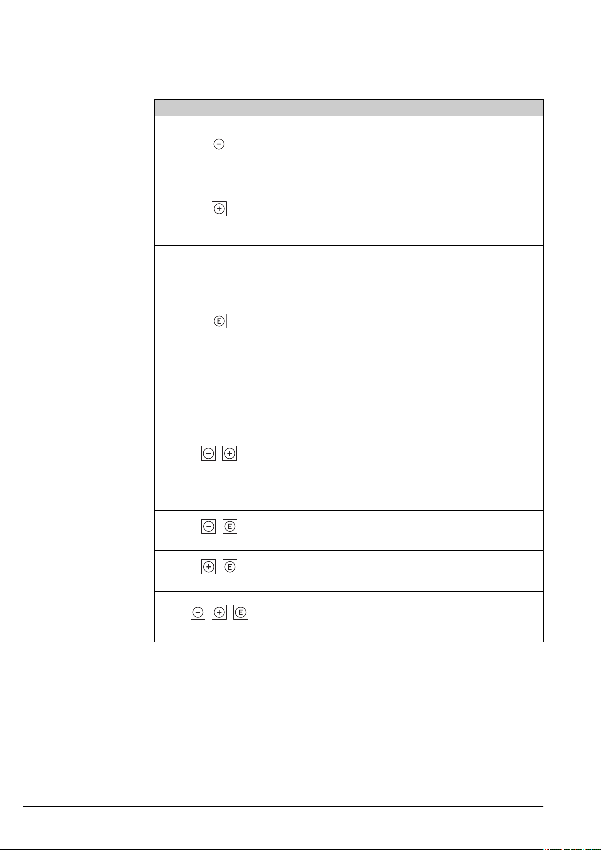
Operating elements
+
+
+
++
Key Meaning
Minus key
For menu, submenu
Moves the selection bar upwards in a picklist.
A0013969
For text and numeric editor
In the input mask, moves the selection bar to the left (backwards).
Plus key
For menu, submenu
Moves the selection bar downwards in a picklist.
A0013970
For text and numeric editor
In the input mask, moves the selection bar to the right (forwards).
Enter key
For measured value display
Pressing the key briefly opens the operating menu.
•
• Pressing the key for 2 s opens the context menu.
For menu, submenu
• Pressing the key briefly
Opens the selected menu, submenu or parameter.
• Pressing the key for 2 s for parameter:
A0013952
If present, opens the help text for the function of the parameter.
For text and numeric editor
• Pressing the key briefly
– Opens the selected group.
– Carries out the selected action.
• Pressing the key for 2 s confirms the edited parameter value.
Escape key combination (press keys simultaneously)
For menu, submenu
Pressing the key briefly
•
– Exits the current menu level and takes you to the next higher level.
– If help text is open, closes the help text of the parameter.
A0013971
• Pressing the key for 2 s returns you to the measured value display ("home
position").
For text and numeric editor
Closes the text or numeric editor without applying changes.
Minus/Enter key combination (press and hold down the keys
simultaneously)
A0013953
Reduces the contrast (brighter setting).
Plus/Enter key combination (press and hold down the keys
simultaneously)
A0013954
Increases the contrast (darker setting).
Minus/Plus/Enter key combination (press and hold down the keys
simultaneously)
For measured value display
A0013955
Enables or disables the keypad lock.
Levelflex FMP53
54 Endress+Hauser
Page 55
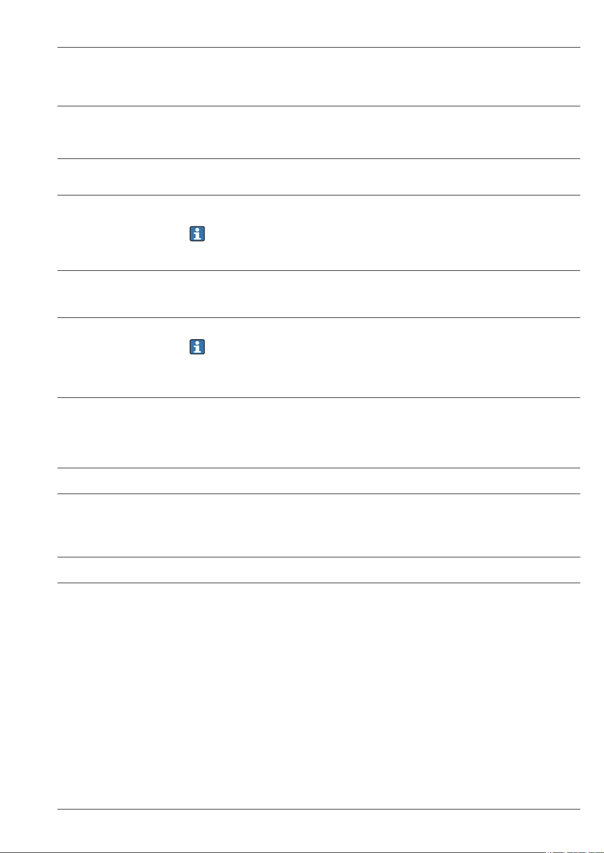
Levelflex FMP53
Certificates and approvals
CE mark
C-Tick symbol
Ex approval
Functional Safety
Sanitary compatibility
Pharma (CoC)
The measuring system meets the legal requirements of the applicable EC guidelines. These are listed in the
corresponding EC Declaration of Conformity together with the standards applied.
Endress+Hauser confirms successful testing of the device by affixing to it the CE mark.
The measuring system meets the EMC requirements of the "Australian Communications and Media
Authority (ACMA)".
The devices are certified for use in hazardous areas and the relevant safety instructions are provided in the
separate "Safety Instructions" (XA) document. Reference is made to this document on the nameplate.
The separate documentation "Safety Instructions" (XA) containing all the relevant explosion protection
data is available from your Endress+Hauser Sales Center. Correlation of documentations to the device
(® ä 67).
Used for level monitoring (MIN, MAX, range) up to SIL 3 (homogeneous redundancy), independently
assessed by TÜV Rhineland as per IEC 61508. Other information see documentation SD00326F: "Functional
Safety Manual".
Overview of permitted process connections (® ä 40)
The gap-free connections can be cleaned without residue using the usual cleaning methods.
Many versions of the Levelflex M meet the requirements of 3A-Sanitary Standard No. 74.
Endress+Hauser confirms this by attaching the 3A symbol.
Certificate of Compliance (CoC)
•
Ordering information (® ä 59), feature 590 "Additional Approval:", option "LW"
• Materials in contact with process made of 316L with delta-ferrite < 3 %
•
Surface roughness Ra < 0.38 mm (15 min)
• Information on ASME BPE Conformity
AD2000
Telecommunications
Track record
Other standards and guidelines
The pressure retaining material 316L (1.4435/1.4404) corresponds to AD2000 - W2/W10.
Complies with part 15 of the FCC rules for an unintentional radiator. All probes meet the requirements for a
Class A digital device.
In addition, all probes in metallic tanks as well as the coax probe meet the requirements for a Class B digital
device.
FMP5x is the upgrade model of the corresponding FMP4x series.
•
EN 60529
Degrees of protection by housing (IP code)
• EN 61010-1
Protection Measures for Electrical Equipment for Measurement, Control, Regulation and Laboratory
Procedures.
• IEC/EN 61326
"Emission in accordance with Class A requirements". Electromagnetic compatibility (EMC requirements)
• NAMUR NE 21
Electromagnetic compatibility (EMC) of industrial process and laboratory control equipment.
• NAMUR NE 43
Standardization of the signal level for the breakdown information of digital transmitters with analog output
signal.
• NAMUR NE 53
Software of field devices and signal-processing devices with digital electronics
Endress+Hauser 55
Page 56
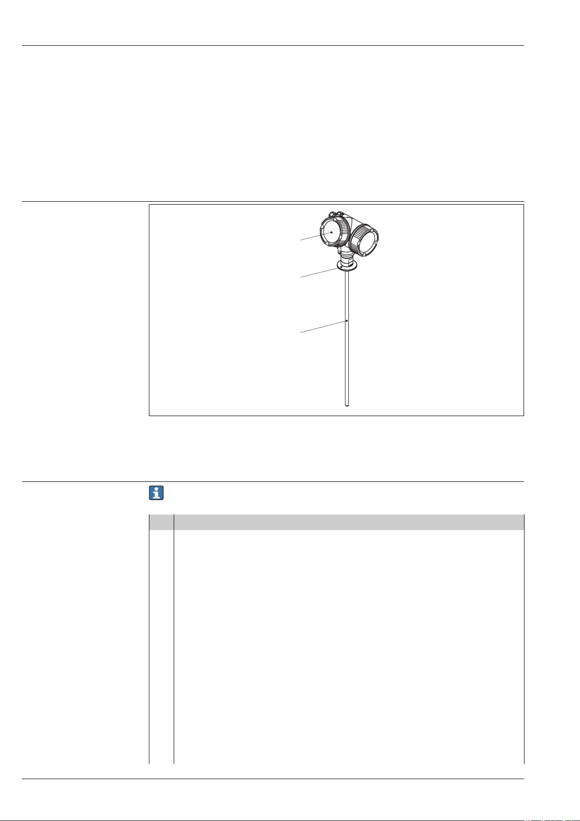
Compact device Levelflex
1
2
3
• NAMUR NE 107
Status classification as per NE107
NAMUR NE 131
•
Requirements for field devices for standard applications
• IEC61508
Functional safety of electrical/electronic/programmable electronic safety-related systems
Ordering information
Levelflex FMP53
Product structure FMP53
Design of the Levelflex
å 19
1 Electronics housing
2 Process connection
3 Rod probe
This overview does not mark options which are mutually exclusive.
Option with * = in preparation
010 Approval:
AA Non-hazardous area
BA ATEX II 1G Ex ia IIC T6
BB ATEX II 1/2G Ex ia IIC T6
BC ATEX II 1/2G Ex d(ia) IIC T6
BD ATEX II 1/3G Ex ic(ia) IIC T6
BG ATEX II 3G Ex nA IIC T6
BH ATEX II 3G Ex ic IIC T6
BL ATEX II 1/3G Ex nA(ia) IIC T6
B2 ATEX II 1/2G Ex ia IIC T6, 1/2D Ex ia IIIC IP6x
B3 ATEX II 1/2G Ex d(ia) IIC T6, 1/2D Ex tD IIIC IP6x
B4 ATEX II 1/2G Ex ia IIC T6, Ex d(ia) IIC T6
CA CSA General Purpose
C2 CSA C/US IS Cl.I,II,III Div.1 Gr.A-G, NI Cl.1 Div.2, Ex ia
C3 CSA C/US XP Cl.I,II,III Div.1 Gr.A-G, NI Cl.1 Div.2, Ex d
FB FM IS Cl.I,II,III Div.1 Gr.A-G, AEx ia, NI Cl.1 Div.2
A0013421
56 Endress+Hauser
Page 57
Levelflex FMP53
010 Approval:
FD FM XP Cl.I,II,III Div.1 Gr.A-G, AEx d, NI Cl.1 Div.2
IA IEC Ex Zone 0 Ex ia IIC T6 Ga
IB IEC Ex Zone 0/1 Ex ia IIC T6 Ga/Gb
IC IEC Ex Zone 0/1 Ex d(ia) IIC T6 Ga/Gb
ID IEC Ex Zone 0/2 Ex ic(ia) IIC T6 Ga/Gc
IG IEC Ex Zone 2 Ex nA IIC T6 Gc
IH IEC Ex Zone 2 Ex ic IIC T6 Gc
IL IECEx zone 0/2 Ex nA(ia) IIC T6 Ga/Gc
I2 IECEx zone 0/1 Ex ia IIC T6 Ga/Gb, zone 20/21 Ex ia IIIC A20/21 IP6x Da/Db
I3 IEC Ex Zone 0/1 Ex d(ia) IIC T6 Ga/Gb, Zone 20/21 Ex tD IIIC A20/21 IP6x Da/Db
NA NEPSI zone 0 Ex ia IIC T6 Ga
NB NEPSI zone 0/1 Ex ia IIC T6 Ga/Gb
NC NEPSI zone 0/1 Ex d(ia) IIC T6 Ga/Gb
NG NEPSI zone 2 Ex nA II T6 Gc
NH NEPSI zone 2 Ex ic IIC T6 Gc
N2 NEPSI zone 0/1 Ex ia IIC T6 Ga/Gb, zone 20/21 Ex iaD 20/21 T*
N3 NEPSI zone 0/1 Ex d(ia) IIC T6 Ga/Gb, DIP A20/21 T* IP6x
8A FM/CSA IS+XP Cl.I,II,III Div.1 Gr.A-G
99 Special version, TSP-no. to be sepc.
020 Power Supply, Output
A 2-wire; 4-20mA HART
C 2-wire; 4-20mA HART, 4-20mA
E 2-wire; FOUNDATION Fieldbus, switch output
G 2-wire; PROFIBUS PA, switch oputput
K 4-wire 90-253VAC; 4-20mA HART
L 4-wire 10,4-48VDC; 4-20mA HART
Y Special version, TSP-no. to be sepc.
030 Display, Operation:
A W/o, via communication
C SD02 4-line, push buttons + data backup function
Y Special version, TSP-no. to be sepc.
040 Housing:
A GT19 dual compartment, Plastics PBT
C GT20 dual compartment, Alu coated
Y Special version, TSP-no. to be sepc.
050 Electrical connection:
A Gland M20, IP66/68 NEMA4X/6P
B Thread M20, IP66/68 NEMA4X/6P
C Thread G1/2, IP66/68 NEMA4X/6P
D Thread NPT1/2, IP66/68 NEMA4X/6P
I Plug M12, IP66/68 NEMA4X/6P
M Plug 7/8", IP66/68 NEMA4X/6P
Y Special version, TSP-no. to be sepc.
Endress+Hauser 57
Page 58
060 Probe:
DA
..... mm, rod 8mm 316L, Ra<0.76mm/30min
DB
..... in, rod 0.31in 316L, Ra<0.76mm/30min
EA
..... mm, rod 8mm 316L, ep=electro-polished, Ra<0.38mm/15min
EB
..... in, rod 0.31in 316L, ep=electro-polished,Ra<0.38mm/15min
FA
..... mm, rod 8mm 316L, Ra, 500mm divisible Ra<0.76mm/30min
FB
..... in, rod 0.31in 316L, Ra, 20in divisible Ra<0.76mm/30min
GA
..... mm, rod 8mm 316L, ep, Ra, 500mm divisible, ep=electro-polished, Ra<0.38mm/15min
GB
..... in, rod 0.31in 316L, ep, Ra, 20in divisible, ep=electro-polished,Ra<0.38mm/15min
HA
..... mm, rod 8mm 316L, Ra, 1000mm divisible Ra<0.76mm/30min
HB
..... in, rod 0.31in 316L, Ra, 40in divisible Ra<0.76mm/30min
IA
..... mm, rod 8mm 316L, ep, Ra, 1000mm divisible, ep=electro-polished Ra<0.38mm/15min
IB
..... in, rod 0.31in 316L, ep, Ra, 40in divisible, ep=electro-polished,Ra<0.38mm/15min
YY Special version, TSP-no. to be sepc.
090 Seal:
AD FKM; FDA, USP Cl.VI, -10...150°C (14...302°F)
B5 EPDM, FDA, USP Cl.VI, -20...130°C (-2...266°F)
C4 Kalrez, FDA, USP Cl.VI, -20...150°C (-4...302°F)
Y9 Special version, TSP-no. to be sepc.
100 Process connection:
MAJ DIN11864-1 A DN25 tube DIN11866-A, 316L
MDJ DIN11864-1 A DN50 tube DIN11866-A, 316L
MOJ DIN11851 DN50 PN40 cap-nut, 316L
MQJ DIN11851 DN40 PN40 cap-nut, 316L
S1J NEUMO BioControl D25 PN16, 316L
S4J NEUMO BioControl D50 PN16, 316L
S6J NEUMO BioControl D80 PN16, 316L
TDJ Tri-Clamp ISO2852 DN40-51 (2"), 3A, 316L
TFJ Tri-Clamp ISO2852 DN70-76.1 (3"), 3A, 316L
TOJ Tri-Clamp ISO2852 DN25-38 (1...1-1/2"), 3A, 316L
TSJ Varivent pipe DN40-162 PN16, 316L
TXJ SMS 2" PN25, 316L
T7J SMS 1-1/2" PN25, 316L
UVJ Ingold fitting 25x46 mm, 316L
U1J Thread M24, 316L, install > accessory weld-in adapter
YYY Special version, TSP-no. to be sepc.
500 Additional Operation Language:
AA English
AB German
AC French
AD Spanish
AE Italian
AF Dutch
AG Portuguese
Levelflex FMP53
58 Endress+Hauser
Page 59
Levelflex FMP53
500 Additional Operation Language:
AH Polish
AI Russian
AK Chinese simplified
AL Japanese
AM Korean
AR Czech
550 Calibration:
F4
5-point linearity protocol (® ä 61)
F9 Special version, TSP-no. to be sepc.
570
Service: (Multiple options can be selected)
IJ
Customized parametrization HART (® ä 61)
IK
Customized parametrization PA (® ä 61)
IL
Customized parametrization FF (® ä 61)
IW W/o Tooling DVD (FieldCare setup)
I9 Special version, TSP-no. to be sepc.
580
Test, Certificate: (Multiple options can be selected)
JA 3.1 Material certificate, wetted metallic parts, EN10204-3.1 inspection certificate
KB Surface finishmeasurement ISO4287/Ra, wetted metallic parts, inspection certificate
KE Pressure test, internal procedure, inspection certificate
KF 3.1 Material certificate+Delta-Ferrit measurement, internal procedure, wetted metallic parts, EN10204-3.1
inspection certificate
K9 Special version, TSP-no. to be sepc.
590
Additional Approval: (Multiple options can be selected)
LA SIL
LC *WHG overfill prevention
LW CoC-ASME BPE
L9 Special version, TSP-no. to be sepc.
600
Probe Design: (Multiple options can be selected)
MA Sensor compact, detachable
MB Sensor remote, 3m/9ft cable, detachable+mounting bracket
MC Sensor remote, 6m/19ft cable, detachable+mounting bracket
M9 Special version, TSP-no. to be sepc.
1)
1) The versions with Ingold fitting (feature 100, option UVJ) and NEUMO BioControl D50 or D80 (feature 100,
options S4J or S6J) are always detachable. Therefore, option MA needs not to be selected in these cases.
620
Accessory Enclosed: (Multiple options can be selected)
PB Weather protection cover
R9 Special version, TSP-no. to be sepc.
850 Firmware Version:
75 01.01.zz, HART, DevRev02
76 01.00.zz, FF, DevRev01
77 01.00.zz, PROFIBUS PA, DevRev01
78 01.00.zz, HART, DevRev01
Endress+Hauser 59
Page 60

895
Tagging: (Multiple options can be selected)
Z1 Tagging (TAG), see additional spec.
Z2 Bus address, see additional spec.
Levelflex FMP53
60 Endress+Hauser
Page 61
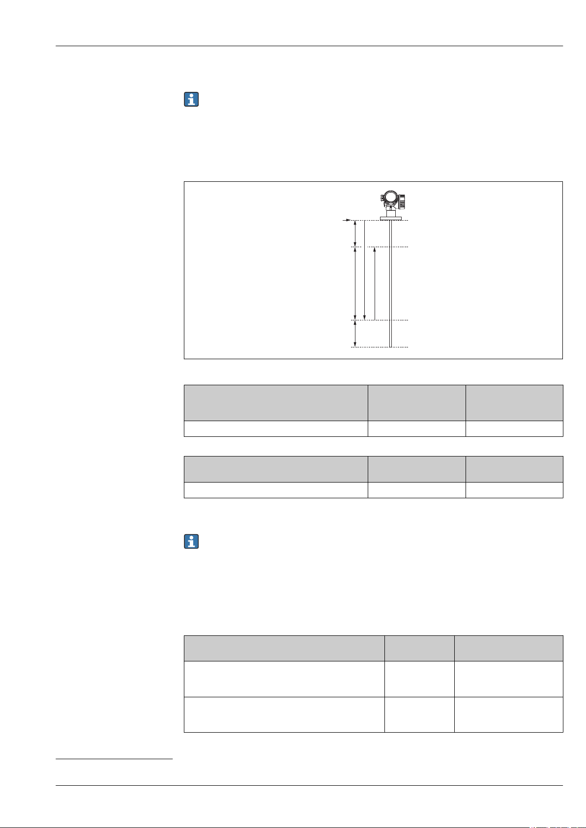
Levelflex FMP53
R
A
C
B
F
E
5-point linearity protocol
The following notes must be taken into account if option F4 ("5 point linearity protocol") has been
selected in feature 550 ("Calibration").
The five points of the linearity protocol are evenly distributetd throughout the measuring range (0% to
100%). In order to define the measuring range, Empty calibration (E) and Full calibration (F) have to be
4)
specified
.
The following restrictions have to be taken into account when defining E and F:
A0015167
Sensor Minimum distance
between reference point
(R) and 100% level
FMP53
Type of probe Minimum distance from
Rod
A ³ 250 mm (10 in) B ³ 400 mm (16 in)
end of probe to 0% level
C ³ 100 mm (4 in) E £ 3.9 m (12.8 ft)
Minimum measuring
range
Maximum value for
"empty calibration"
The linearity check is performed with the complete device and under reference conditions.
The selected values of Empty calibration and Full calibration are only used to record the linearity
protocol and are reset to their probe specific default values thereafter. If values different from the
default are required, they must be ordered as a customized parametrization (® ä 61).
Customized parametrization
If the option IJ "Customized parametrization HART", IK "Customized parametrization PA" or IL "Customized
parametrization FF" has been selected in feature 570 "Service", customer specific presettings can be selected
for the following parameters:
Parameter Communication Selection list / range of
values
Setup ® Distance unit
Setup ® Empty calibration
• HART
PA
•
• FF
• HART
• PA
• FF
• in
• mm
0 to 6 m (0 to 18 ft)
4) If E and F are not specified, probe dependent default values will be used instead.
Endress+Hauser 61
Page 62
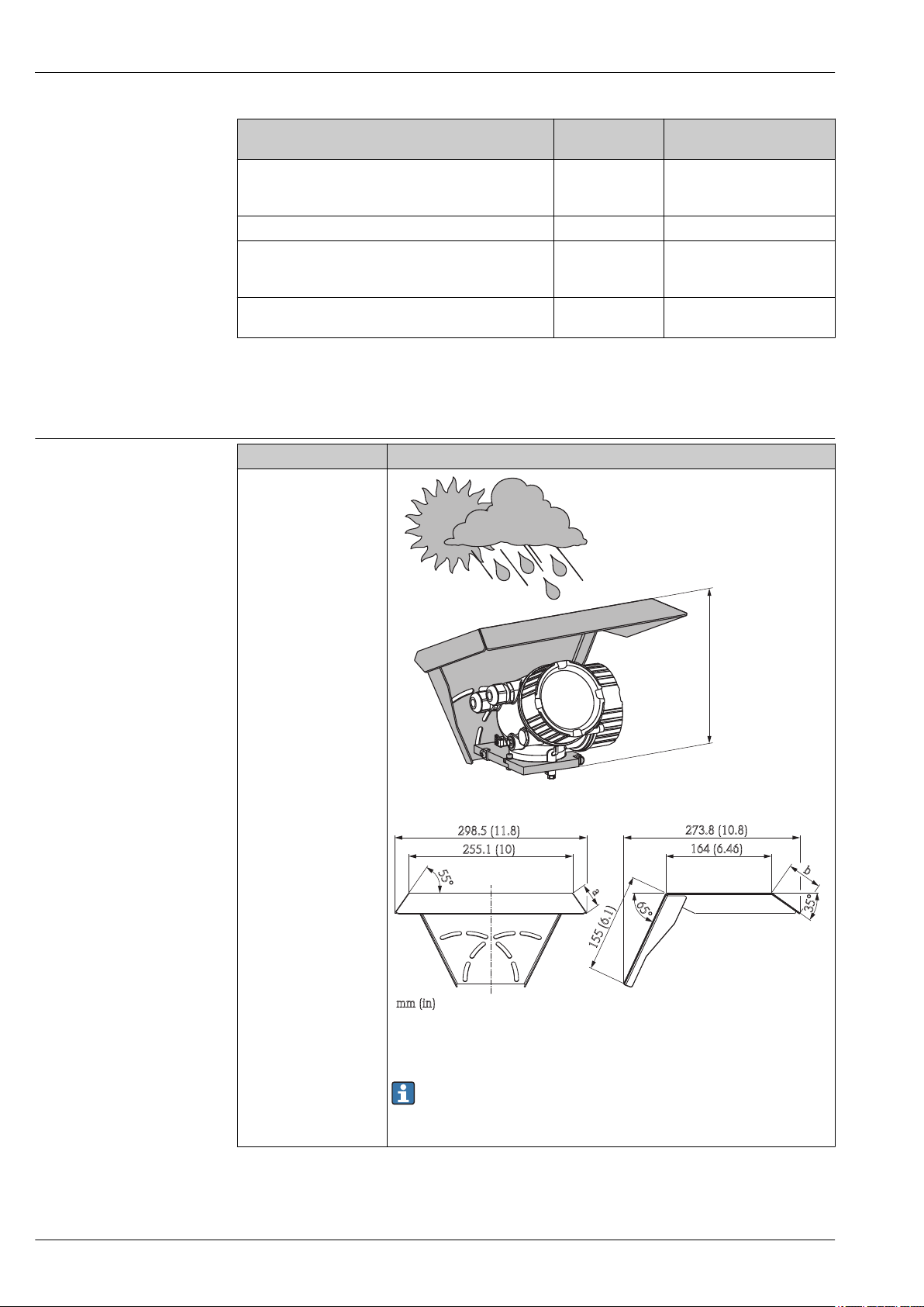
Levelflex FMP53
222 (8.74)
mm (in)
55°
35°
b
164(6.46)
273.8(10.8)
155(6.1)
65°
255.1(10)
mm(in)
298.5(11.8)
a
Parameter Communication Selection list / range of
values
Setup ® Full calibration
Setup ® Adv. Setup ® Current output 1/2 ® Damping
Setup ® Adv. Setup ® Current output 1/2 ® Failure mode
Expert ® Comm. ® HART config. ® Burst mode
• HART
PA
•
• FF
HART 0 to 999,9 s
HART • Min
HART • Off
0 to 6 m (0 to 18 ft)
•
Max
• Last valid value
• On
Accessories
Device-specific accessories
Accessory Description
Weather protection cover
A0015466
a 37.8 mm (1.49 in)
b 54 mm (2.13 in)
The weather protection cover can be ordered together with the device (product
structure, feature 620 "Accessory Enclosed", option PB "Weather Protection
Cover").
Alternatively, it can be separately ordered as an accessory; order code 71132889.
62 Endress+Hauser
A0015472
Page 63
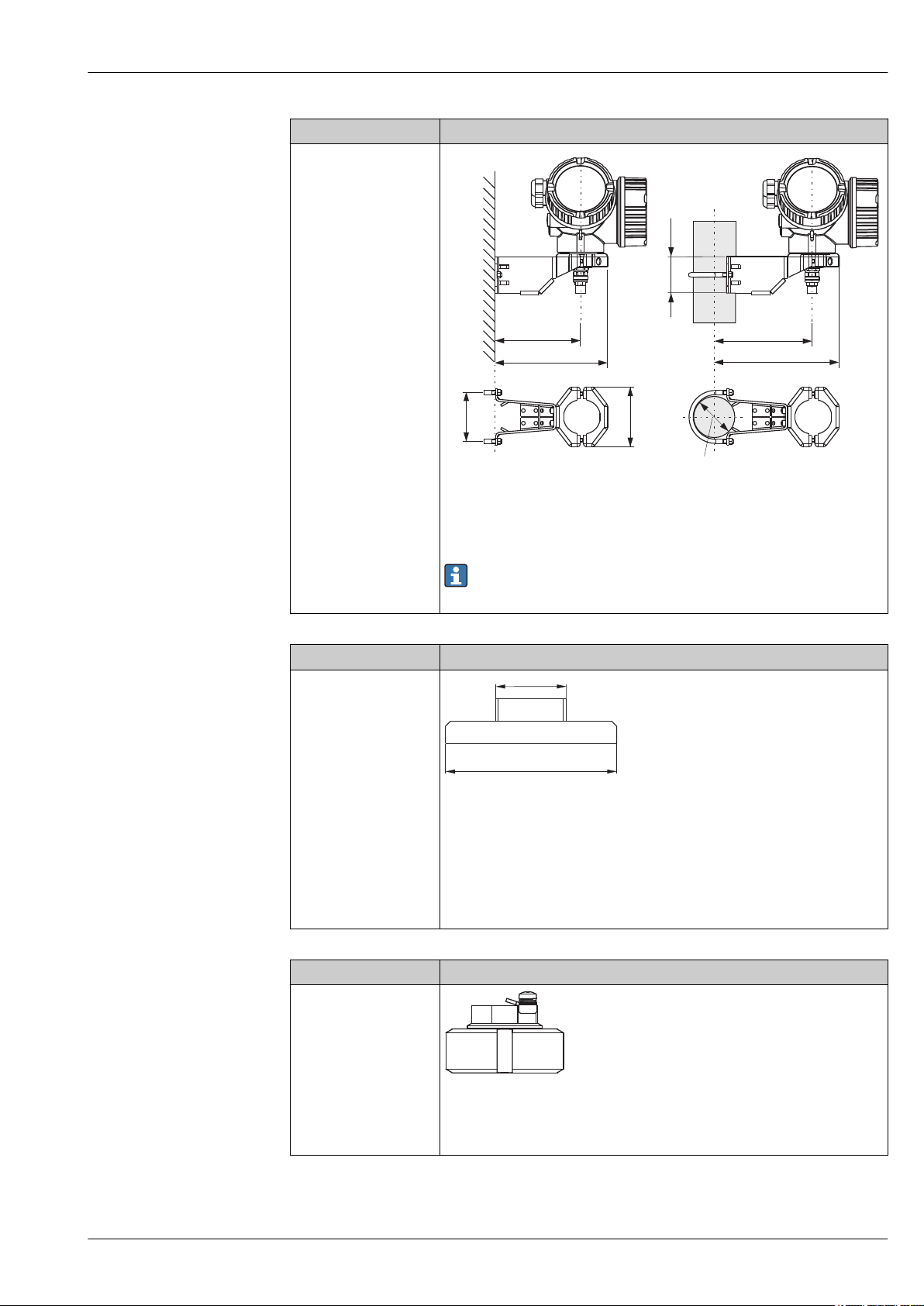
Levelflex FMP53
122(4.8)
52
(2)
86
(3.4)
70
(2.8)
140(5.5)
158(6.2)
175(6.9)
A B
mm(inch)
Ø42...60
(1-1/4...2)
Ø65(2.56)
M24x1,5
mm(inch)
Accessory Description
Mounting bracket for the
electronics housing
A0014793
A Wall mounting
B Pipe mounting
For the "Sensor remote" device version (see feature 060 of the product structure),
the mounting bracket is part of the delivery. If required, it can also be ordered as an
accessory (order code 71102216).
Accessory Description
Weld-in adpater
M24 D65
With M24x1.5 thread for flush-mounted sensors.
Material: 1.4435 (AISI 316L)
Weight: 0.22 kg (0.48 lbs)
Order No.
Standard version: 71041381
•
• with 3.1 material certificate: 71041383
For details see Operating Instructions BA361F.
Accessory Description
Protective cover
A0013588
With the protective cover the probe can be locked with dismantled electronics.
Order no.: 71041379
For details refer to Operating Instructions BA362F.
Endress+Hauser 63
A0013589
Page 64
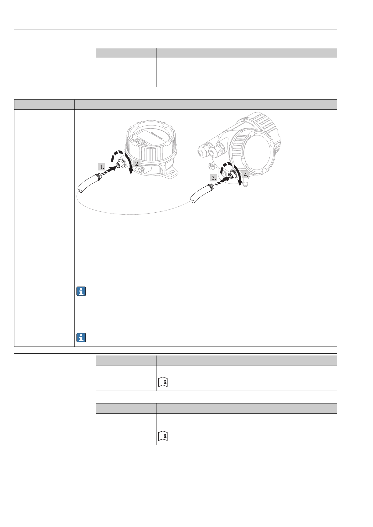
Accessory Description
Remote display FHX50
Levelflex FMP53
Accessory Description
Calibration kit The calibration kit is used to regularly test the accuracy and reproducibility of the
Levelflex FMP53 level measurement device.
Order No.: 71041382
For details refer to Operating Instructions SD01003F.
Communication-specific accessories
Material:
•
– Plastics PBT
– 316L (in preparation)
• Suitable for the display modules:
– SD02 (push buttons)
– SD03 (touch control) (in preparation)
• Connection cable:
– Cable with M12 plug; supplied with the FHX50; up to 30 m (98 ft)
– Customer supplied standard cable; up to 60 m (196 ft)
• If the remote display is to be used, the Levelflex must be ordered in the version "Prepared for display FHX50" (feature
030, option L or M). For the FHX50, on the other hand, the option A: "Prepared for display FHX50" has to be selected in
feature 050: "Option Measurement Device".
If a Levelflex has not been ordered in the version "Prepared for display FHX50", but is nevertheless to be equipped with an
•
FHX50, it is essential to select the option B: "Not prepared for display FHX50" in feature 050: "Option Measurement
Device" of the FHX50. In this case, a retrofit kit, needed to prepare the Levelflex for the remote display, is supplied
together with the FHX50.
For details refer to the document SD01007F.
Accessory Description
Commubox FXA195 HART For intrinsically safe HART communication with FieldCare via the USB interface.
For details refer to Technical Information TI404F/00
A0019128
Accessory Description
Commubox FXA291 Connects Endress+Hauser field devices with CDI interface (= Endress+Hauser Common
Data Interface) to the USB interface of a computer.
For details refer to Technical Information TI405C/07
64 Endress+Hauser
Page 65
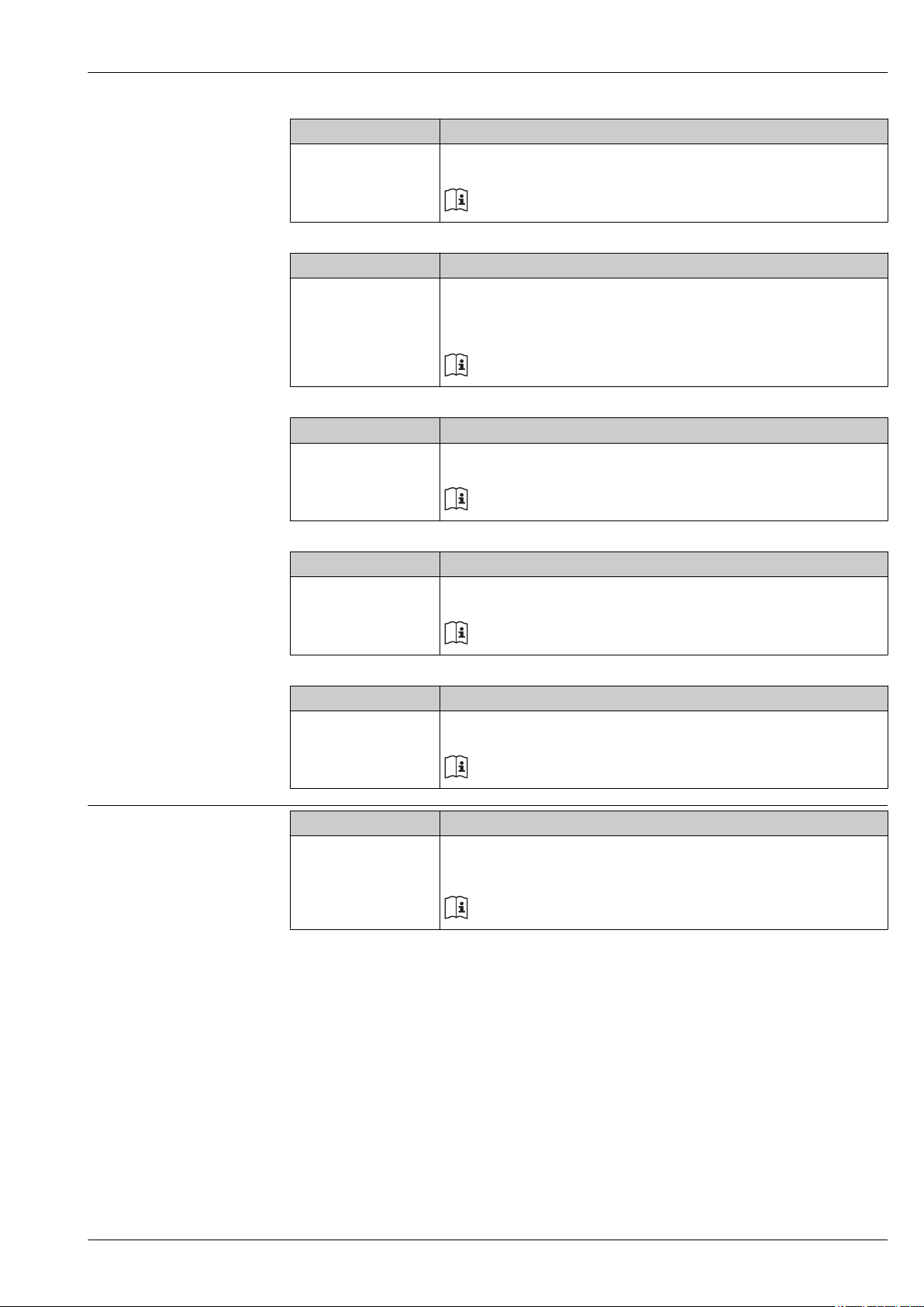
Levelflex FMP53
Accessory Description
HART Loop Converter
HMX50
Accessory Description
WirelessHART Adapter
SWA70
Accessory Description
Fieldgate FXA320 Gateway for remote monitoring of connected 4-20mA measuring devices via web
Evaluates the dynamic HART variables and converts them to analog current signals or
limit values.
For details refer to Technical Information TI429F/00 and Operating Instructions
BA371F/00
Connects field devices to a WirelessHART network.
The WirelessHART adapter can be mounted directly at a HART device and is easly
integrated into an existing HART network. It ensures safe data transmission and can be
operated in parallel with other wireless networks.
For details refer to Operating Instructions BA061S/04
browser.
For details refer to Technical Information TI025S/04 and Operating Instructions
BA053S/04
Service-specific accessories
Accessory Description
Fieldgate FXA520 Gateway for remote diagnosis and parametrization of connected HART measuring devices
via web browser.
For details refer to Technical Information TI025S/04/xx and Operating
Instructions BA051S/04
Accessory Description
Field Xpert SFX100 Compact, flexible and robust industry handheld terminal for remote parametrization and
measured value inspection via the HART output or via FOUNDATION Fieldbus .
For details refer to Operating Instructions BA060S/04
Accessory Description
FieldCare Endress+Hauser's FDT-based Plant Asset Management tool.
Helps to configure and maintain all field devices of your plant. By supplying status
information it also supports the diagnosis of the devices.
For details refer to Operating Instructions BA027S/04 and BA059S/04
Endress+Hauser 65
Page 66
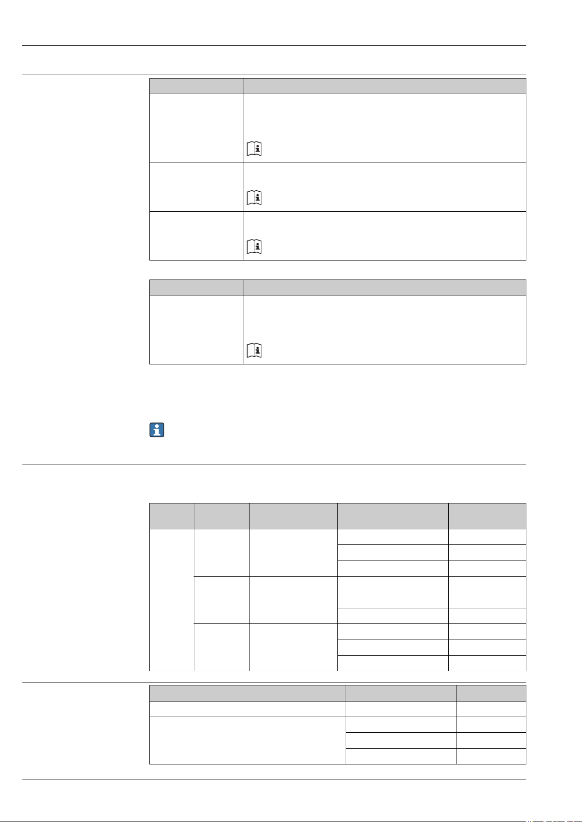
Levelflex FMP53
System components
Accessory Description
Graphic Data Manager
Memograph M
RN221N Active barrier with power supply for safe separation of 4 to 20 mA current circuits.
RNS221 Transmitter supply for 2-wire sensors or transmitters exclusively for non-Ex areas.
Accessory Description
Graphic Data Manager
Memograph M
The graphic data manager Memograph M provides information on all the relevant process
variables. Measured values are recorded correctly, limit values are monitored and
measuring points analyzed. The data are stored in the 256 MB internal memory and also
on an SD card or USB stick.
For details refer to Technical Information TI133R/09 and Operating Instructions
BA247R/09
Provides bi-directional HART transmission.
For details refer to Technical Information TI073R/09 and Operating Instructions
BA202R/09
Provides bi-directional communication using the HART communication sockets.
For details refer to Technical Information TI081R/09 and Operating Instructions
KA110R/09
The graphic data manager Memograph M provides information on all the relevant process
variables. Measured values are recorded correctly, limit values are monitored and
measuring points analyzed. The data are stored in the 256 MB internal memory and also
on an SD card or USB stick.
For details refer to Technical Information TI133R/09 and Operating Instructions
BA247R/09
Documentation
The following document types are available:
On the CD supplied with the device
•
•
In the Download Area of the Endress+Hauser Internet site: www.endress.com ® Download
Standard documentation Levelflex FMP53
Correlation of documentations to the device:
Device Power supply,
output
FMP53 A, B, C, K, L HART Operating Instructions BA01002F/00/DE
G PROFIBUS PA Operating Instructions BA01007F/00/DE
E FOUNDATION Fieldbus Operating Instructions BA01053F/00/EN
Supplementary documentation
Device Document type Document code
Fieldgate FXA520 Technical Information TI369F/00/EN
Tank Side Monitor NRF590 Technical Information TI402F/00/EN
Communication Document type Document code
Brief Operating Instructions KA01078F/00/DE
Description of Device Parameters GP01000F/00/DE
Brief Operating Instructions KA01080F/00/DE
Description of Device Parameters GP01001F/00/DE
Brief Operating Instructions KA01108F/00/EN
Description of Device Parameters GP01015F/00/EN
Operating Instructions BA256F/00/EN
Description of Device Parameters BA257F/00/EN
66 Endress+Hauser
Page 67
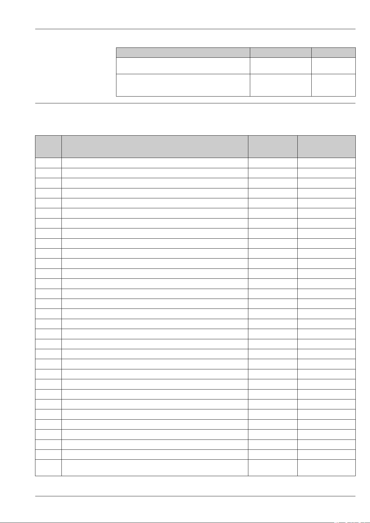
Levelflex FMP53
Description Document type Document code
Time of Flight Liquid Level Measurement
Selection and engineering for the process industry
Radar Tank Gauging brochure
For inventory control and custody transfer applications in tank
farms and terminals
Certificates Safety Instructions (XA) for Levelflex FMP53
Depending on the approval, the following Safety Instructions (XA) are supplied with the instrument. They
are an integral part of the Operating Instructions.
Special Documentation SD157F/00/EN
Special Documentation SD001V/00/EN
Feature
010
Approval Safety Instructions
HART
BA ATEX II 1 G Ex ia IIC T6 Ga XA00496F XA00516F
BB ATEX II 1/2 G Ex ia IIC T6 Ga/Gb XA00496F XA00516F
BC ATEX II 1/2 G Ex d[ia] IIC T6 Ga/Gb XA00499F XA00519F
BD ATEX II 1/3 G Ex ic[a] IIC T6 Ga/Gc XA00497F XA00517F
BG ATEX II 3 G Ex nA IIC T6 Gc XA00498F XA00518F
BH ATEX II 3 G Ex ic IIC T6 Gc XA00498F XA00518F
BL ATEX II 1/3G Ex nA(ia) IIC T6 XA00497F XA00517F
B2 ATEX II 1/2 G Ex ia IIC T6 Ga/Gb, II 1/2 D Ex t[ia] IIIC Txx°C Da/Db IP6x XA00502F XA00522F
B3 ATEX II 1/2 G Ex d[ia] IIC T6 Ga/Gb, II 1/2 D Ex t[ia] IIIC Txx°C Da/Db IP6x XA00503F XA00523F
B4 ATEX II 1/2 G Ex ia IIC T6 Ga/Gb, Ex d[ia] IIC T6 Ga/Gb XA00500F XA00520F
C2 CSA C/US IS Cl.I,II,III Div.1 Gr.A-G, NI Cl.1 Div.2, Ex ia XA00530F XA00571F
C3 CSA C/US XP Cl.I,II,III Div.1 Gr.A-G, NI Cl.1 Div.2, Ex d XA00529F XA00570F
FB FM IS Cl.I,II,III Div.1 Gr.A-G, AEx ia, NI Cl.1 Div.2 XA00531F XA00573F
FD FM XP Cl.I,II,III Div.1 Gr.A-G, AEx d, NI Cl.1 Div.2 XA00532F XA00572F
IA IECEx zone 0 Ex ia IIC T6 Ga XA00496F XA00516F
IB IECEx zone 0/1 Ex ia IIC T6 Ga/Gb XA00496F XA00516F
IC IECEx zone 0/1 Ex d[ia] IIC T6 Ga/Gb XA00499F XA00519
ID IECEx zone 0/2 Ex ic[ia] IIC T6 Ga/Gc XA00497F XA00517F
IG IECEx zone 2 Ex nA IIC T6 Gc XA00498F XA00518F
IH IECEx zone 2 Ex ic IIC T6 Gc XA00498F XA00518F
IL IECEx zone 0/2 Ex nA(ia) IIC T6 Ga/Gc XA00497F XA00517F
I2 IECEx zone 0/1 Ex ia IIC T6 Ga/Gb, zone 20/21 Ex t[ia] IIIC Txx°C Da/Db IP6x XA00502F XA00522F
I3 IECEx zone 0/1 Ex d[ia] IIC T6 Ga/Gb, zone 20/21 Ex t[ia] IIIC Txx°C Da/Db IP6x XA00503F XA00523F
NA NEPSI Zone 0 Ex ia IIC T6 Ga XA00634F XA00640F
NB NEPSI Zone 0/1 Ex ia IIC T6 Ga/Gb XA00634F XA00640F
NC NEPSI Zone 0/1 Ex d(ia) IIC T6 Ga/Gb XA00636F XA00642F
NG NEPSI Zone 2 Ex nA II T6 Gc XA00635F XA00641F
NH NEPSI Zone 2 Ex ic IIC T6 Gc XA00635F XA00641F
N2 NEPSI Zone 0/1 Ex ia IIC T6 Ga/Gb, Zone 20/21 Ex tD IIIC A20/21 IP6x Da/Db XA00638F XA00644F
N3 NEPSI Zone 0/1 Ex d(ia) IIC T6 Ga/Gb, Zone 20/21 Ex tD IIIC A20/21 IP6x Da/Db XA00639F XA00645F
8A FM/CSA IS+XP Cl.I,II,III Div.1 Gr.A-G XA00531F
XA00532F
Safety Instructions
PROFIBUS
FOUNDATION Fieldbus
XA00572F
XA00573F
Endress+Hauser 67
Page 68
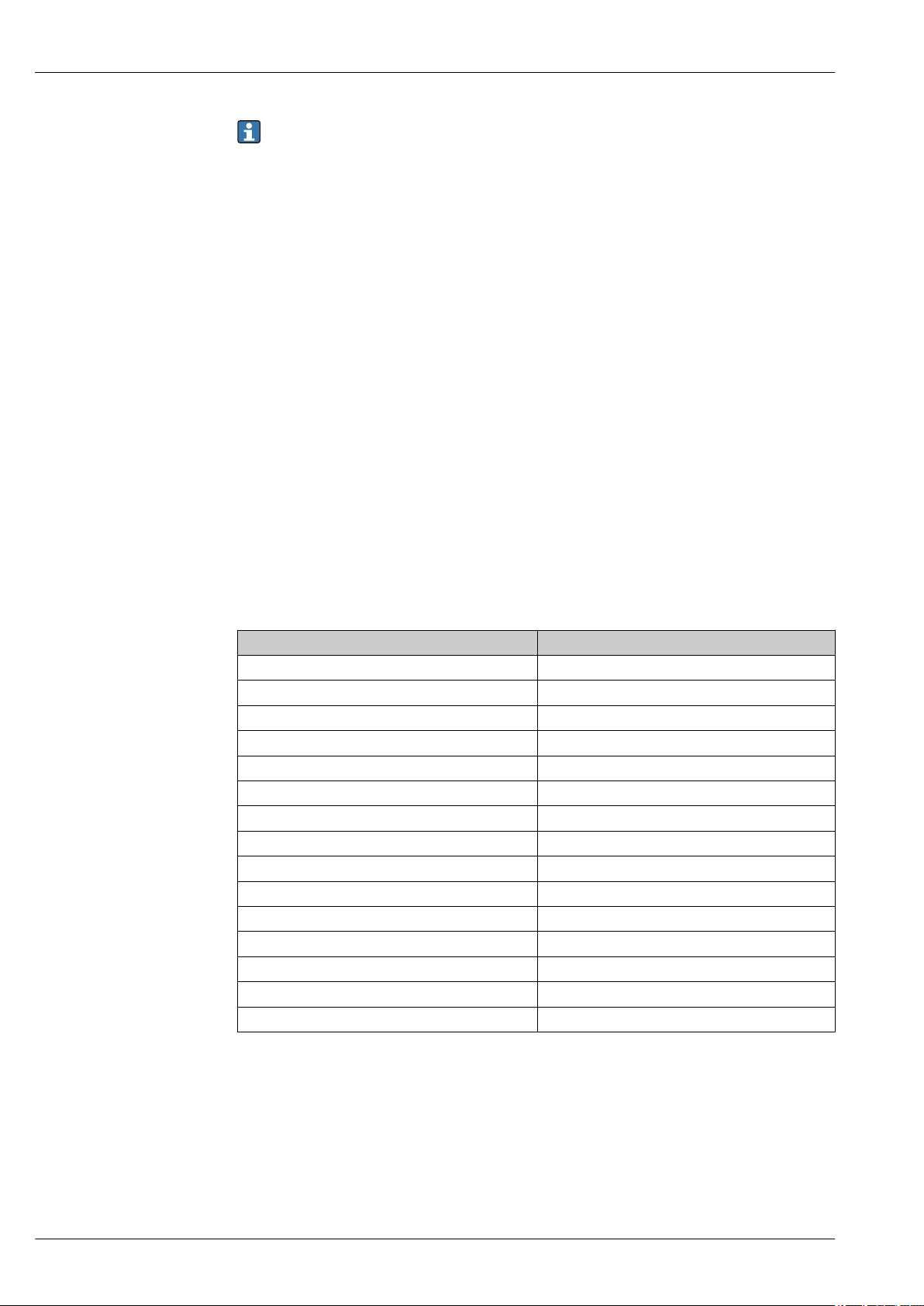
For certified devices the relevant Safety Instructions are indicated on the nameplate.
Registered trademarks
Ò
HART
Registered trademark of the HART Communication Foundation, Austin, USA
PROFIBUS
Registered trademark of the PROFIBUS User Organization, Karlsruhe, Germany
FOUNDATIONTM Fieldbus
Registered trademark of the Fieldbus Foundation, Austin, Texas, USA
KALREZÒ, VITON
Registered trademark of DuPont Performance Elastomers L.L.C., Wilmington, USA
TEFLON
Registered trademark of E.I. DuPont de Nemours & Co., Wilmington, USA
TRI CLAMP
Registered trademark of Alfa Laval Inc., Kenosha, USA
Ò
Ò
Ò
Ò
Levelflex FMP53
Patents
This product may be protected by at least one of the following patents.
Further patents are pending.
US Patents EP Patents
5.827.985 ---
5.884.231 ---
5.973.637 ---
6.087.978 955 527
6.140.940 ---
6.481.276 ---
6.512.358 1 301 914
6.559.657 1 020 735
6.640.628 ---
6.691.570 ---
6.847.214 ---
7.441.454 ---
7.477.059 ---
--- 1 389 337
7.965.087 ---
68 Endress+Hauser
Page 69

Page 70

Page 71

Page 72

Instruments International
Endress+Hauser
Instruments International AG
Kaegenstrasse 2
4153 Reinach
Switzerland
Tel.+41 61 715 81 00
Fax+41 61 715 25 00
www.endress.com
[email protected]
TI01002F/00/EN/15.12
71206471
CCS/EH-COSIMA ProMoDo
*71206471*
71206471
 Loading...