

Endress+Hauser Levelflex FMP55, Levelflex FMP54, Levelflex FMP52 Operating Instructions Manual

BA01003F/00/EN/18.16
71344071
01.03.zz (Device firmware)
Products Solutions Services
Operating Instructions
Levelflex FMP55
HART
Guided wave radar

Order code:
Ext. ord. cd.:
Ser. no.:
www.endress.com/deviceviewer
Endress+Hauser
Operations App
XXXXXXXXXXXX
XXXXX-XXXXXX
XXX.XXXX.XX
Serial number
1.
3.
2.
A0023555
2 Endress+Hauser

Table of contents
Table of contents
1 Important document information .... 5
1.1 Document function ..................... 5
1.2 Symbols .............................. 5
1.2.1 Safety symbols .................. 5
1.2.2 Electrical symbols ................ 5
1.2.3 Tool symbols .................... 6
1.2.4 Symbols for certain types of
information .................... 6
1.2.5 Symbols in graphics ............... 6
1.2.6 Symbols at the device ............. 7
1.3 Supplementary documentation ............. 8
1.3.1 Safety Instructions (XA) ............ 9
2 Basic safety instructions ........... 12
2.1 Requirements for the personnel ........... 12
2.2 Designated use ....................... 12
2.3 Workplace safety ...................... 13
2.4 Operational safety ..................... 13
2.5 Product safety ........................ 13
2.5.1 CE mark ...................... 13
2.5.2 EAC conformity ................. 13
3 Product description ................ 14
3.1 Product design ........................ 14
3.1.1 Levelflex FMP51/FMP52/FMP54/
FMP55 ....................... 14
3.1.2 Electronics housing .............. 15
3.2 Registered trademarks .................. 16
4 Incoming acceptance and product
identification ..................... 17
4.1 Incoming acceptance ................... 17
4.2 Product identification .................. 17
4.2.1 Nameplate .................... 18
5 Storage, Transport ................ 19
5.1 Storage conditions ..................... 19
5.2 Transport product to the measuring point .... 19
6 Mounting ......................... 21
6.1 Mounting requirements ................. 21
6.1.1 Suitable mounting position ........ 21
6.1.2 Applications with restricted
mounting space ................. 22
6.1.3 Notes on the mechanical load of the
probe ........................ 23
6.1.4 Mounting cladded flanges ......... 24
6.1.5 Securing the probe .............. 25
6.1.6 Special mounting conditions ....... 26
6.2 Mounting the device ................... 30
6.2.1 Required mounting tools .......... 30
6.2.2 Mounting the device ............. 30
6.2.3 Mounting the "Sensor remote"
version ....................... 30
6.2.4 Turning the transmitter housing .... 32
6.2.5 Turning the display module ........ 33
6.3 Post-installation check .................. 34
7 Electrical connection .............. 35
7.1 Connection conditions .................. 35
7.1.1 Terminal assignment ............. 35
7.1.2 Cable specification ............... 41
7.1.3 Device plug connectors ........... 42
7.1.4 Power supply .................. 43
7.1.5 Overvoltage protection ........... 45
7.2 Connecting the device .................. 45
7.2.1 Pluggable spring-force terminals .... 46
7.3 Post-connection check .................. 47
8 Operation options ................. 48
8.1 Overview ............................ 48
8.1.1 Local operation ................. 48
8.1.2 Operation with remote display and
operating module FHX50 .......... 49
8.1.3 Remote operation ............... 49
8.2 Structure and function of the operating
menu .............................. 51
8.2.1 Structure of the operating menu .... 51
8.2.2 User roles and related access
authorization .................. 53
8.2.3 Write protection via access code ..... 54
8.2.4 Disabling write protection via access
code ......................... 55
8.2.5 Deactivation of the write protection
via access code ................. 55
8.2.6 Write protection via write protection
switch ........................ 56
8.2.7 Enabling and disabling the keypad
lock ......................... 58
8.3 Display and operating module ............ 59
8.3.1 Display appearance .............. 59
8.3.2 Operating elements .............. 62
8.3.3 Entering numbers and text ........ 63
8.3.4 Opening the context menu ......... 65
8.3.5 Envelope curve on the display and
operating module ............... 66
9 Device integration via the HART
protocol .......................... 67
9.1 Overview of the Device Description files
(DD) ............................... 67
9.2 HART device variables and measuring
values .............................. 67
Endress+Hauser 3

Table of contents
10 Commissioning via wizard ......... 68
11 Commissioning via operating
menu ............................. 69
11.1 Installation and function check ............ 69
11.2 Setting the operating language ............ 69
11.3 Configuration of an interface measurement .. 70
11.4 Recording the reference curve ............ 72
11.5 Configuration of the on-site display ........ 73
11.5.1 Factory settings of the on-site
display for interface measurements .. 73
11.5.2 Adjustment of the on-site display ... 73
11.6 Configuration of the current outputs ........ 74
11.6.1 Factory setting of the current
outputs for interface measurements .. 74
11.6.2 Adjustment of the current outputs ... 74
11.7 Configuration management .............. 75
11.8 Protection of the settings against
unauthorized changes .................. 76
12 Diagnostics and troubleshooting ... 77
12.1 General trouble shooting ................ 77
12.1.1 General errors .................. 77
12.1.2 Parametrization errors ........... 78
12.2 Diagnostic information on local display ...... 79
12.2.1 Diagnostic message .............. 79
12.2.2 Calling up remedial measures ...... 81
12.3 Diagnostic event in the operating tool ....... 82
12.4 Diagnostic list ........................ 82
12.5 List of diagnostic events ................. 83
12.6 Event logbook ........................ 85
12.6.1 Event history ................... 85
12.6.2 Filtering the event logbook ........ 85
12.6.3 Overview of information events ..... 85
12.7 Firmware history ...................... 87
15.1.2 Mounting bracket for the electronics
housing ...................... 92
15.1.3 Centering star .................. 92
15.1.4 Remote display FHX50 ........... 93
15.1.5 Overvoltage protection ........... 94
15.2 Communication-specific accessories ........ 95
15.3 Service-specific accessories ............... 96
15.4 System components .................... 96
16 Operating menu ................... 97
16.1 Overview of the operating menu (display
module) ............................ 97
16.2 Overview of the operating menu (operating
tool) .............................. 104
16.3 "Setup" menu ........................ 111
16.3.1 "Mapping" wizard ............... 121
16.3.2 "Advanced setup" submenu ........ 122
16.4 "Diagnostics" menu .................... 172
16.4.1 "Diagnostic list" submenu ......... 174
16.4.2 "Event logbook" submenu ......... 175
16.4.3 "Device information" submenu ..... 176
16.4.4 "Measured values" submenu ....... 179
16.4.5 "Data logging" submenu .......... 182
16.4.6 "Simulation" submenu ........... 185
16.4.7 "Device check" submenu .......... 190
16.4.8 "Heartbeat" submenu ............ 192
Index ................................. 193
13 Maintenance ...................... 88
13.1 Exterior cleaning ...................... 88
13.2 Cleaning coax probes ................... 88
14 Repairs ........................... 89
14.1 General information on repairs ............ 89
14.1.1 Repair concept ................. 89
14.1.2 Repairs to Ex-approved devices ..... 89
14.1.3 Replacement of an electronics
module ....................... 89
14.1.4 Replacement of a device .......... 89
14.2 Spare parts .......................... 90
14.3 Return .............................. 90
14.4 Disposal ............................ 90
15 Accessories ....................... 91
15.1 Device-specific accessories ............... 91
15.1.1 Weather protection cover ......... 91
4 Endress+Hauser

Levelflex FMP55 HART Important document information
DANGER
WARNING
CAUTION
NOTICE
1 Important document information
1.1 Document function
These Operating Instructions contain all the information that is required in various phases
of the life cycle of the device: from product identification, incoming acceptance and
storage, to mounting, connection, operation and commissioning through to
troubleshooting, maintenance and disposal.
1.2 Symbols
1.2.1 Safety symbols
Symbol Meaning
DANGER!
This symbol alerts you to a dangerous situation. Failure to avoid this situation will
result in serious or fatal injury.
WARNING!
This symbol alerts you to a dangerous situation. Failure to avoid this situation can
result in serious or fatal injury.
CAUTION!
This symbol alerts you to a dangerous situation. Failure to avoid this situation can
result in minor or medium injury.
NOTE!
This symbol contains information on procedures and other facts which do not result in
personal injury.
1.2.2 Electrical symbols
Symbol Meaning
Direct current
Alternating current
Direct current and alternating current
Ground connection
A grounded terminal which, as far as the operator is concerned, is grounded via a
grounding system.
Protective ground connection
A terminal which must be connected to ground prior to establishing any other
connections.
Equipotential connection
A connection that has to be connected to the plant grounding system: This may be a
potential equalization line or a star grounding system depending on national or
company codes of practice.
Endress+Hauser 5

Important document information Levelflex FMP55 HART
A
1.
1.
1.2.3 Tool symbols
Symbol Meaning
Torx screwdriver
A0013442
Flat blade screwdriver
A0011220
Cross-head screwdriver
A0011219
Allen key
A0011221
Hexagon wrench
A0011222
1.2.4 Symbols for certain types of information
Symbol Meaning
Permitted
Procedures, processes or actions that are permitted.
Preferred
Procedures, processes or actions that are preferred.
Forbidden
Procedures, processes or actions that are forbidden.
Tip
Indicates additional information.
Reference to documentation
Reference to page
Reference to graphic
Notice or individual step to be observed
, 2., 3.… Series of steps
Result of a step
Help in the event of a problem
Visual inspection
1.2.5 Symbols in graphics
Symbol Meaning
1, 2, 3 ... Item numbers
, 2., 3.… Series of steps
A, B, C, ... Views
A-A, B-B, C-C, ... Sections
6 Endress+Hauser

Levelflex FMP55 HART Important document information
-
.
Symbol Meaning
Hazardous area
Indicates a hazardous area.
Safe area (non-hazardous area)
Indicates the non-hazardous area.
1.2.6 Symbols at the device
Symbol Meaning
Safety instructions
Observe the safety instructions contained in the associated Operating Instructions.
Temperature resistance of the connection cables
Specifies the minimum value of the temperature resistance of the connection cables.
Endress+Hauser 7

Important document information Levelflex FMP55 HART
1.3 Supplementary documentation
Document Purpose and content of the document
Technical Information
TI01003F (FMP55)
Brief Operating Instructions
KA01060F (FMP55, HART)
Description of Device Parameters
GP01000F (FMP5x, HART)
Special documentation
SD00326F
Special documentation
SD01872F
Planning aid for your device
The document contains all the technical data on the device and provides
an overview of the accessories and other products that can be ordered for
the device.
Guide that takes you quickly to the 1st measured value
The Brief Operating Instructions contain all the essential information
from incoming acceptance to initial commissioning.
Reference for your parameters
The document provides a detailed explanation of each individual
parameter in the operating menu. The description is aimed at those who
work with the device over the entire life cycle and perform specific
configurations.
Functional Safety Manual
The document is part of the Operating Instructions and serves as a
reference for application-specific parameters and notes.
Manual for Heartbeat Verification and Heartbeat Monitoring
The document contains descriptions of the additonal parameters and
technical data which are available with the Heartbeat Verification and
Heartbeat Monitoring application packages.
For an overview of the scope of the associated Technical Documentation, refer to the
following:
• The W@M Device Viewer : Enter the serial number from the nameplate
(www.endress.com/deviceviewer)
• The Endress+Hauser Operations App: Enter the serial number from the nameplate
or scan the 2-D matrix code (QR code) on the nameplate.
8 Endress+Hauser

Levelflex FMP55 HART Important document information
1.3.1 Safety Instructions (XA)
Depending on the approval, the following Safety Instructions (XA) are supplied with the
device. They are an integral part of the Operating Instructions.
Feature 010 Approval Available for Feature 020: "Power Supply; Output"
1)
A
BA ATEX II 1G Ex ia IIC T6 Ga FMP55 XA00496F XA01125F XA01126F XA00516F -
BB ATEX II 1/2G Ex ia IIC T6 Ga/Gb FMP55 XA00496F XA01125F XA01126F XA00516F -
BC ATEX II 1/2G Ex d[ia] IIC T6 Ga/Gb FMP55 XA00499F XA00499F XA00499F XA00519F XA01133F
BD ATEX II 1/3G Ex ic[ia] IIC T6 Ga/Gc FMP55 XA00497F XA01127F XA01128F XA00517F -
BG ATEX II 3G Ex nA IIC T6 Gc FMP55 XA00498F XA01130F XA01131F XA00518F XA01132F
BH ATEX II 3G Ex ic IIC T6 Gc FMP55 XA00498F XA01130F XA01131F XA00518F -
BL ATEX II 1/3G Ex nA[ia] IIC T6 Ga/Gc FMP55 XA00497F XA01127F XA01128F XA00517F XA01129F
B2 ATEX II 1/2G Ex ia IIC T6 Ga/Gb, 1/2D Ex ia IIIC Da/Db FMP55 XA00502F XA00502F XA00502F XA00522F -
B3 ATEX II 1/2G Ex d[ia] IIC T6 Ga/Gb, 1/2 D Ex t IIIC
Da/Db
B4 ATEX II 1/2G Ex ia IIC T6 Ga/Gb, Ex d[ia] IIC T6 Ga/Gb FMP55 XA00500F XA01134F XA01135F XA00520F -
C2 CSA C/US IS Cl.I,II,III Div.1 Gr.A-G, NI Cl.1 Div.2, Ex ia FMP55 XA00530F XA00530F XA00530F XA00571F XA00530F
C3 CSA C/US XP Cl.I,II,III Div.1 Gr.A-G, NI Cl.1 Div.2, Ex d FMP55 XA00529F XA00529F XA00529F XA00570F XA00529F
FB FM IS Cl.I,II,III Div.1 Gr.A-G, AEx ia, NI Cl.1 Div.2 FMP55 XA00531F XA00531F XA00531F XA00573F XA00531F
FD FM XP Cl.I,II,III Div.1 Gr.A-G, AEx d, NI Cl.1 Div.2 FMP55 XA00532F XA00532F XA00532F XA00572F XA00532F
GA EAC Ex ia IIC T6 Ga FMP55 XA01380F XA01380F XA01380F XA01381F XA01380F
GB EAC Ex ia IIC T6 Ga/Gb FMP55 XA01380F XA01380F XA01380F XA01381F XA01380F
GC EAC Ex d[ia] IIC T6 Ga/Gb FMP55 XA01382F XA01382F XA01382F XA01383F XA01382F
IA IEC Ex ia IIC T6 Ga FMP55 XA00496F XA01125F XA01126F XA00516F -
IB IEC Ex ia IIC T6 Ga/Gb FMP55 XA00496F XA01125F XA01126F XA00516F -
IC IEC Ex d[ia] IIC T6 Ga/Gb FMP55 XA00499F XA00499F XA00499F XA00519F XA01133F
ID IEC Ex ic[ia] IIC T6 Ga/Gc FMP55 XA00497F XA01127F XA01128F XA00517F -
IG IEC Ex nA IIC T6 Gc FMP55 XA00498F XA01130F XA01131F XA00518F XA01132F
IH IEC Ex ic IIC T6 Gc FMP55 XA00498F XA01130F XA01131F XA00518F -
IL IEC Ex nA[ia] IIC T6 Ga/Gc FMP55 XA00497F XA01127F XA01128F XA00517F XA01129F
I2 IEC Ex ia IIC T6 Ga/Gb, Ex ia IIIC Da/Db FMP55 XA00502F XA00502F XA00502F XA00522F -
I3 IEC Ex d [ia] IIC T6 Ga/Gb, Ex t IIIC Da/Db FMP55 XA00503F XA00503F XA00503F XA00523F XA01136F
I4 IEC Ex II 1/2G Ex ia IIC T6 Ga/Gb, Ex d[ia] IIC T6 Ga/Gb FMP55 XA00500F XA01134F XA01135F XA00520F -
KA KC Ex ia IIC T6 Ga FMP55 XA01169F - XA01169F - -
KB KC Ex ia IIC T6 Ga/Gb FMP55 XA01169F - XA01169F - -
KC KC Ex d[ia] IIC T6 FMP55 - - XA01170F - -
MA INMETRO Ex ia IIC T6 Ga FMP55 XA01038F XA01038F XA01038F - XA01038F
MC INMETRO Ex d[ia] IIC T6 Ga/Gb FMP55 XA01041F XA01041F XA01041F - XA01041F
MH INMETRO Ex ic IIC T6 Gc FMP55 XA01040F XA01040F XA01040F - XA01040F
NA NEPSI Ex ia IIC T6 Ga FMP55 XA00634F XA00634F XA00634F XA00640F XA00634F
NB NEPSI Ex ia IIC T6 Ga/Gb FMP55 XA00634F XA00634F XA00634F XA00640F XA00634F
NC NEPSI Ex d[ia] IIC T6 Ga/Gb FMP55 XA00636F XA00636F XA00636F XA00642F XA00636F
NG NEPSI Ex nA II T6 Gc FMP55 XA00635F XA00635F XA00635F XA00641F XA00635F
NH NEPSI Ex ic IIC T6 Gc FMP55 XA00635F XA00635F XA00635F XA00641F XA00635F
FMP55 XA00503F XA00503F XA00503F XA00523F XA01136F
2)
B
3)
C
4)/G 5)
E
6)/L 7)
K
Endress+Hauser 9

Important document information Levelflex FMP55 HART
Feature 010 Approval Available for Feature 020: "Power Supply; Output"
1)
A
2)
B
3)
C
4)/G 5)
E
6)/L 7)
K
N2 NEPSI Ex ia IIC T6 Ga/Gb, Ex iaD 20/21 T85…90°C FMP55 XA00638F XA00638F XA00638F XA00644F XA00638F
N3 NEPSI Ex d[ia] IIC T6 Ga/Gb, DIP A20/21 T85…90°C
FMP55 XA00639F XA00639F XA00639F XA00645F XA00639F
IP66
8A FM/CSA IS+XP Cl.I,II,III Div.1 Gr.A-G FMP55 XA00531F
XA00532F
XA00531F
XA00532F
XA00531F
XA00532F
XA00572F
XA00573F
XA00531F
XA00532F
1) A: 2-wire; 4-20mA HART
2) B: 2-wire; 4-20mA HART, switch output
3) C: 2-wire; 4-20mA HART, 4-20mA
4) E: 2-wire; FOUNDATION Fieldbus, switch output
5) G: 2-wire; PROFIBUS PA, switch output
6) K: 4-wire 90-253VAC; 4-20mA HART
7) L: 4-wire 10,4-48VDC; 4-20mA HART
For certified devices the relevant Safety Instructions (XA) are indicated on the
nameplate.
10 Endress+Hauser

Levelflex FMP55 HART Important document information
Ex-marking in case of connected FHX50 remote display
If the device is prepared for the remote display FHX50 (product structure: feature 030:
Display, Operation", option L or M), the Ex marking of some certificates changes according
to the following table
Feature 010 ("Approval") Feature 030 ("Display, Operation") Ex-marking
BG L or M ATEX II 3G Ex nA [ia Ga] IIC T6 Gc
BH L or M ATEX II 3G Ex ic [ia Ga] IIC T6 Gc
B3 L or M ATEX II 1/2G Ex d [ia] IIC T6 Ga/Gb,
IG L or M IECEx Ex nA [ia Ga] IIC T6 Gc
IH L or M IECEx Ex ic [ia Ga] IIC T6 Gc
I3 L or M IECEx Ex d [ia] IIC T6 Ga/Gb,
1)
:
ATEX II 1/2D Ex ta [ia Db] IIIC Txx°C Da/Db
IECEx Ex ta [ia Db] IIIC Txx°C Da/Db
1) The marking of certificates not mentioned in this table are not affected by the FHX50.
Endress+Hauser 11

Basic safety instructions Levelflex FMP55 HART
2 Basic safety instructions
2.1 Requirements for the personnel
The personnel for installation, commissioning, diagnostics and maintenance must fulfill
the following requirements:
Trained, qualified specialists must have a relevant qualification for this specific function
‣
and task.
Are authorized by the plant owner/operator.
‣
Are familiar with federal/national regulations.
‣
Before starting work, read and understand the instructions in the manual and
‣
supplementary documentation as well as the certificates (depending on the
application).
Follow instructions and comply with basic conditions.
‣
The operating personnel must fulfill the following requirements:
Are instructed and authorized according to the requirements of the task by the facility's
‣
owner-operator.
Follow the instructions in this manual.
‣
2.2 Designated use
Application and measured materials
The measuring device described in these Operating Instructions is intended only for level
and interface measurement of liquids. Depending on the version ordered the device can
also measure potentially explosive, flammable, poisonous and oxidizing materials.
Observing the limit values specified in the "Technical data" and listed in the Operating
Instructions and supplementary documentation, the measuring device may be used for the
following measurements only:
Measured process variable: Level and/or interface
‣
Calculated process variable: Volume oder mass in arbitrarily shaped vessels (calculated
‣
from the level by the linearization functionality)
To ensure that the measuring device remains in proper condition for the operation time:
Use the measuring device only for measured materials against which the process-
‣
wetted materials are adequately resistant.
Observe the limit values in "Technical data".
‣
Incorrect use
The manufacturer is not liable for damage caused by improper or non-designated use.
Verification for borderline cases:
For special measured materials and cleaning agents, Endress+Hauser is glad to provide
‣
assistance in verifying the corrosion resistance of wetted materials, but does not accept
any warranty or liability.
Residual risk
The electronics housing and its built-in components such as display module, main
electronics module and I/O electronics module may heat to 80 °C (176 °F) during operation
through heat transfer from the process as well as power dissipation within the electronics.
During operation the sensor may assume a temperature near the temperature of the
measured material.
Danger of burns due to heated surfaces!
For high process temperatures: Install protection against contact in order to prevent
‣
burns.
12 Endress+Hauser

Levelflex FMP55 HART Basic safety instructions
2.3 Workplace safety
For work on and with the device:
Wear the required personal protective equipment according to federal/national
‣
regulations.
2.4 Operational safety
Risk of injury.
Operate the device in proper technical condition and fail-safe condition only.
‣
The operator is responsible for interference-free operation of the device.
‣
Conversions to the device
Unauthorized modifications to the device are not permitted and can lead to unforeseeable
dangers.
If, despite this, modifications are required, consult with the manufacturer.
‣
Repair
To ensure continued operational safety and reliability,
Carry out repairs on the device only if they are expressly permitted.
‣
Observe federal/national regulations pertaining to repair of an electrical device.
‣
Use original spare parts and accessories from the manufacturer only.
‣
Hazardous area
To eliminate a danger for persons or for the facility when the device is used in the
hazardous area (e.g. explosion protection, pressure vessel safety):
Based on the nameplate, check whether the ordered device is permitted for the
‣
intended use in the hazardous area.
Observe the specifications in the separate supplementary documentation that is an
‣
integral part of these Instructions.
2.5 Product safety
This measuring device is designed in accordance with good engineering practice to meet
state-of-the-art safety requirements, has been tested, and left the factory in a condition in
which it is safe to operate. It meets general safety standards and legal requirements.
2.5.1 CE mark
The measuring system meets the legal requirements of the applicable EC guidelines. These
are listed in the corresponding EC Declaration of Conformity together with the standards
applied.
Endress+Hauser confirms successful testing of the device by affixing to it the CE mark.
2.5.2 EAC conformity
The measuring system meets the legal requirements of the applicable EAC guidelines.
These are listed in the corresponding EAC Declaration of Conformity together with the
standards applied.
Endress+Hauser confirms successful testing of the device by affixing to it the EAC mark.
Endress+Hauser 13

Product description Levelflex FMP55 HART
1
2
5
3
4
6
3 Product description
3.1 Product design
3.1.1 Levelflex FMP51/FMP52/FMP54/FMP55
A0012399
1 Design of the Levelflex
1 Electronics housing
2 Process connection (here as an example: flange)
3 Rope probe
4 End-of-probe weight
5 Rod probe
6 Coax probe
14 Endress+Hauser

Levelflex FMP55 HART Product description
Esc
–
+
E
1
2
3
4
5
6
9
7
8
3.1.2 Electronics housing
A0012422
2 Design of the electronics housing
1 Electronics compartment cover
2 Display module
3 Main electronics module
4 Cable glands (1 or 2, depending on instrument version)
5 Nameplate
6 I/O electronics module
7 Terminals (pluggable spring terminals)
8 Connection compartment cover
9 Grounding terminal
Endress+Hauser 15

Product description Levelflex FMP55 HART
3.2 Registered trademarks
®
HART
Registered trademark of the FieldComm Group, Austin, USA
KALREZ®, VITON
Registered trademark of DuPont Performance Elastomers L.L.C., Wilmington, USA
TEFLON
®
Registered trademark of E.I. DuPont de Nemours & Co., Wilmington, USA
TRI CLAMP
Registered trademark of Alfa Laval Inc., Kenosha, USA
®
®
16 Endress+Hauser

Levelflex FMP55 HART Incoming acceptance and product identification
DELIVERYNOTE
1 = 2
DELIVERYNOTE
Madein Germany, 79689 Maulburg
4 Incoming acceptance and product
identification
4.1 Incoming acceptance
Is the order code on the delivery
A0015502
A0022480
A0022486
note (1) identical to the order
code on the product sticker (2)?
Are the goods undamaged?
A0015502
A0022489
Do the nameplate data match the
A0015502
A0022491
ordering information on the
delivery note?
Is the DVD (operating tool)
A0015502
present?
If required (see nameplate): Are
the Safety Instructions (XA)
present?
A0022494
If one of the conditions does not comply, contact your Endress+Hauser distributor.
4.2 Product identification
The following options are available for identification of the measuring device:
• Nameplate specifications
• Order code with breakdown of the device features on the delivery note
• Enter serial numbers from nameplates in W@M Device Viewer
( www.endress.com/deviceviewer ): All information about the measuring device is
displayed.
• Enter the serial number from the nameplates into the Endress+Hauser Operations App
or scan the 2-D matrix code (QR code) on the nameplate with the Endress+Hauser
Operations App: all the information for the measuring device is displayed.
Endress+Hauser 17

Incoming acceptance and product identification Levelflex FMP55 HART
20
21
22
24
25
23
26
1
2
3
4
5
6
7
8
9
10
19
18
17
16
15
14
Ext. ord. cd.:
Order code:
Ser. no.:
LN =
Lref =
Mat.:
Date:
FW:
Dev.Rev.:
DeviceID:
Ta:
if modification
see sep. label
X =
MWP:
12
11
47 (1.85)
92 (3.62)
mm (in)
13
4.2.1 Nameplate
A0010725
3 Nameplate of the Levelflex
1 Device name
2 Address of manufacturer
3 Order code
4 Serial number (Ser. no.)
5 Extended order code (Ext. ord. cd.)
6 Process pressure
7 Gas phase compensation: reference distance
8 Certificate symbol
9 Certificate and approval relevant data
10 Degree of protection: e.g. IP, NEMA
11 Document number of the Safety Instructions: e.g. XA, ZD, ZE
12 2-D matrix code (QR code)
13 Modification mark
14 Manufacturing date: year-month
15 Permitted temperature range for cable
16 Geräterevision (Dev.Rev.)
17 Additional information about the device version (certificates, approvals, communication): e.g. SIL, PROFIBUS
18 Firmware version (FW)
19 CE mark, C-Tick
20 DeviceID
21 Material in contact with process
22 Permitted ambient temperature (Ta)
23 Size of the thread of the cable glands
24 Length of probe
25 Signal outputs
26 Operating voltage
Only 33 digits of the extended order code can be indicated on the nameplate. If the
extended order code exceeds 33 digits, the rest will not be shown. However, the
complete extended order code can be viewed in the operating menu of the device in
the Extended order code 1 to 3 parameter.
18 Endress+Hauser

Levelflex FMP55 HART Storage, Transport
5 Storage, Transport
5.1 Storage conditions
• Permitted storage temperature: –40 to +80 °C (–40 to +176 °F)
• Use the original packaging.
5.2 Transport product to the measuring point
WARNING
L
Housing or probe may be damaged or break away.
Risk of injury!
Transport the measuring device to the measuring point in its original packaging or at
‣
the process connection.
Do not fasten lifting devices (hoisting slings, lifting eyes etc.) at the housing or the
‣
probe but at the process connection. Take into account the mass center of the device in
order to avoid unintended tilting.
Comply with the safety instructions, transport conditions for devices over 18kg
‣
(39.6lbs) (IEC61010).
NOTICE
Shipping lock for FMP5x with coax probe
For FMP5x with coax probe the coax tube is not fixed permanently to the electronics
‣
housing. For shipping and transport it is secured with two cable ties. In order to prevent
the spacer at the probe rod from moving along the probe, these cable ties must not be
loosened when transporting and mounting the device. They may only be undone
directly before screwing the device flange to the process connection.
A0013920
Endress+Hauser 19

Storage, Transport Levelflex FMP55 HART
1 2
4
3
A0015471
20 Endress+Hauser

Levelflex FMP55 HART Mounting
6 Mounting
6.1 Mounting requirements
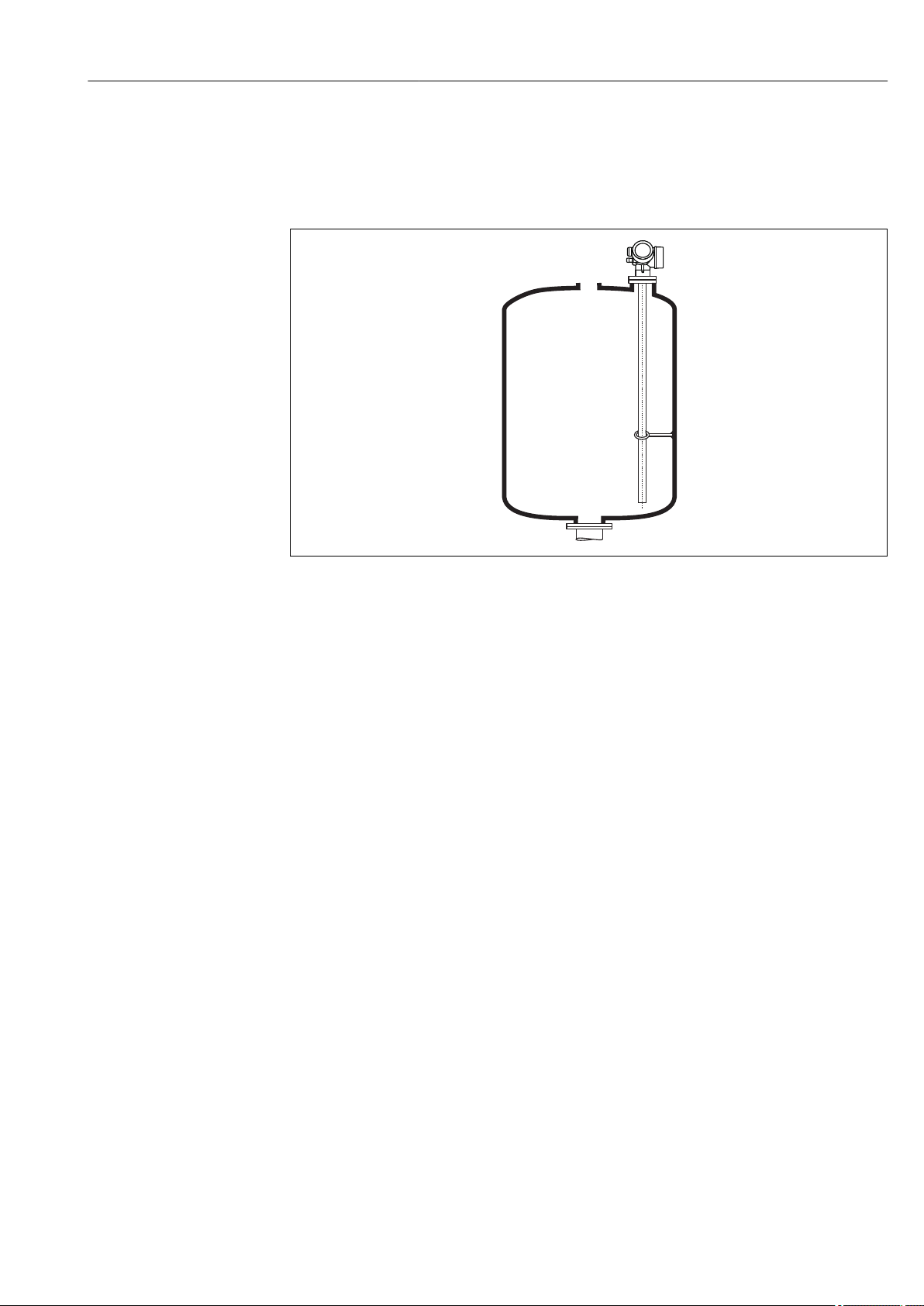
6.1.1 Suitable mounting position
A0011281
4 Mounting position of Levelflex FMP55
• Rod probes / rope probes: must be mounted in a stilling well or bypass → 26.
• Coax probes: can be mounted at an arbitrary distance from the wall of the vessel.
• When mounting in the open, a weather protection cover may be installed to protect the
device against extreme weather conditions.
• Minimum distance from the end of probe to the bottom of the vessel: 10 mm (0.4 in)
Endress+Hauser 21

Mounting Levelflex FMP55 HART
A
B
C
C
r = 100 (4)
min
r = 100 (4)
min
6 Nm
(4.42 lbf ft)
6 Nm
(4.42 lbf ft)
6 Nm
(4.42 lbf ft)
6 Nm
(4.42 lbf ft)
6.1.2 Applications with restricted mounting space
Mounting with remote sensor
The device version with a remote sensor is suited for applications with restricted mounting
space. In this case the electronics housing is mounted at a separate position from which it
is easier accessible.
A0014794
A Angled plug at the probe
B Angled plug at the electronics housing
C Length of the remote cable as ordered
• Product structure, feature 600 "Probe Design":
Option MB "Sensor remote, 3m/9ft cable"
• The remote cable is supplied with these device versions
Minimum bending radius: 100 mm (4 inch)
• A mounting bracket for the electronics housing is supplied with these device versions.
Mounting options:
– Wall mounting
– Pipe mounting; diameter: 42 to 60 mm (1-1/4 to 2 inch)
• The connection cable has got one straight and one angled plug (90°). Depending on the
local conditions the angled plug can be connected at the probe or at the electronics
housing.
Probe, electronics and connection cable are adjusted to match each other. They are
marked by a common serial number. Only components with the same serial number
shall be connected to each other.
22 Endress+Hauser

Levelflex FMP55 HART Mounting
6.1.3 Notes on the mechanical load of the probe
Tensile load limit of rope probes
Sensor Feature 060 Probe Tensile load limit [kN]
FMP55 NA, ND Rope 4mm (1/6") PFA>316 2
Bending strength of rod probes
Sensor Feature 060 Probe Bending strength [Nm]
FMP55 CA, CB Rod 16mm (0.63") PFA>316L 30
Bending strength of coax probes
Sensor Feature 060 Process connection Probe Bending strength [Nm]
FMP55 UA, UB Flange Coax 316L, Ø 42,4 mm 300
Endress+Hauser 23

Mounting Levelflex FMP55 HART
6.1.4 Mounting cladded flanges
• Use flange screws according to the number of flange holes.
• Tighten the screws with the required torque (see table).
• Retighten the screws after 24 hours or after the first temperature cycle.
• Depending on process pressure and process temperature check and retighten the
screws at regular intervals.
Usually, the PTFE flange cladding also serves as a seal between the nozzle and the
device flange.
Flange size Number of screws Recommended torque [Nm]
minimum maximum
EN
DN40/PN40 4 35 55
DN50/PN16 4 45 65
DN50/PN40 4 45 65
DN80/PN16 8 40 55
DN80/PN40 8 40 55
DN100/PN16 8 40 60
DN100/PN40 8 55 80
DN150/PN16 8 75 115
DN150/PN40 8 95 145
ASME
1½"/150lbs 4 20 30
1½"/300lbs 4 30 40
2"/150lbs 4 40 55
2"/300lbs 8 20 30
3"/150lbs 4 65 95
3"/300lbs 8 40 55
4"/150lbs 8 45 70
4"/300lbs 8 55 80
6"/150lbs 8 85 125
6"/300lbs 12 60 90
JIS
10K 40A 4 30 45
10K 50A 4 40 60
10K 80A 8 25 35
10K 100A 8 35 55
10K 100A 8 75 115
24 Endress+Hauser
Levelflex FMP55 HART Mounting
6.1.5 Securing the probe
Securing coax probes
For WHG approvals: For probe lengths ≥ 3 m (10 ft) a support is required.
Coax probes can be supported at any point of the outer tube.
A0012608
Endress+Hauser 25

Mounting Levelflex FMP55 HART
A B
³100
(3.94)
3
21
6.1.6 Special mounting conditions
Bypasses and stilling wells
In bypass and stilling well applications it is recommended to use a centering disks or
stars.
A0014129
1 Mounting in a stilling well
2 Mounting in a bypass
3 Minimum distance between end of probe and lower edge of the bypass; see table below
Minimum distance between end of probe and lower edge of the bypass
Type of probe Minimum distance
Rope 10 mm (0.4 in)
Rod 10 mm (0.4 in)
Coax 10 mm (0.4 in)
• Pipe diameter: > 40 mm (1.6") for rod probes
• Rod probe installation can take place up to a diameter size of 150 mm (6 in). In the
event of larger diameters, a coax probe is recommended.
• Side disposals, holes or slits and welded joints that protrude up to approx. 5 mm (0.2")
inwards do not influence the measurement.
• The pipe may not exhibit any steps in diameter.
• The probe must be 100 mm longer than the lower disposal.
26 Endress+Hauser

Levelflex FMP55 HART Mounting
• Within the measuring range, the probe must not get into contact with the pipe wall. If
necessary, secure the probe by retaining or tensioning. All rope probes are prepared for
tensioning in containers (tensioning weight with anchor hole).
• Within the measuring range, the probe must not get into contact with the pipe wall. If
necessary, use a PFA centering star (see feature 610 of the product structure).
The spacer is also available as an accessory: → 91.
• Coax probes can always be applied if there is enough mounting space.
For bypasses with condensate formation (water) and a medium with low dielectric
constant (e.g. hydrocarbons):
In the course of time the bypass is filled with condensate up to the lower disposal and
for low levels the the level echo is superimposed by the condensate echo. Thus in this
range the condensate level is measured instead of the correct level. Only higher levels
are measured correctly. To prevent this, position the lower disposal 100 mm (4 in)
below the lowest level to be measured and apply a metallic centering disk at the
height of the lower edge of the lower disposal.
With heat insulated tanks the bypass should also be insulated in order to prevent
condensate formation.
For information on bypass solutions from Endress+Hauser please contact your
Endress+Hauser sales representative.
Endress+Hauser 27

Mounting Levelflex FMP55 HART
Underground tanks
A0014142
Use a coax probe for nozzles with large diameters in order to avoid reflections at the
nozzle wall.
Non-metallic vessels
When mounting Levelflex in a non-metallic vessel, use a coax probe.
28 Endress+Hauser

Levelflex FMP55 HART Mounting
40(1.57)
40(1.57)
MAX
mm(in)
MAX
1
3
2
Vessels with heat insulation
If process temperatures are high, the device must be included in normal tank
insulation to prevent the electronics heating up as a result of heat radiation or
convection. The insulation may not exceed beyond the points labeled "MAX" in the
drawings.
A0014654
5 Process connection with flange - FMP55
1 Tank insulation
2 Compact device
3 Sensor remote (feature 600)
Endress+Hauser 29
Mounting Levelflex FMP55 HART
*
6.2 Mounting the device
6.2.1 Required mounting tools
• For flanges and other process connections: appropriate mounting tools
• To turn the housing: Hexagonal wrench 8 mm
6.2.2 Mounting the device
Flange mounting
If a seal is used, be sure to use unpainted metal bolts to ensure good electrical contact
between probe flange and process flange.
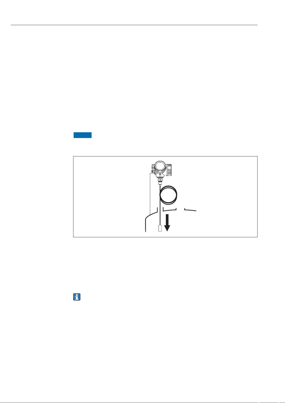
Mounting rope probes
NOTICE
Electrostatic discharges may damage the electronics.
Earth the housing before lowering the rope into the vessel.
‣
A0012852
When lowering the rope probe into the vessel, observe the following:
• Uncoil rope and lower it slowly and carefully into the vessel.
• Do not kink the rope.
• Avoid any backlash, since this might damage the probe or the vessel fittings.
6.2.3 Mounting the "Sensor remote" version
This section is only valid for devices of the version "Probe Design" = "Sensor remote"
(feature 600, option MB/MC/MD).
For the version "Probe design" = "Sensor remote" the following is supplied:
• The probe with the process connection
• The electronics housing
• The mounting bracket for wall or pipe mounting of the electronics housing
• The connection cable (length as ordered). The cable has got one straight and one angled
plug (90°). Depending on the local conditions the angled plug can be connected at the
probe or at the electronics housing.
30 Endress+Hauser
 Loading...