

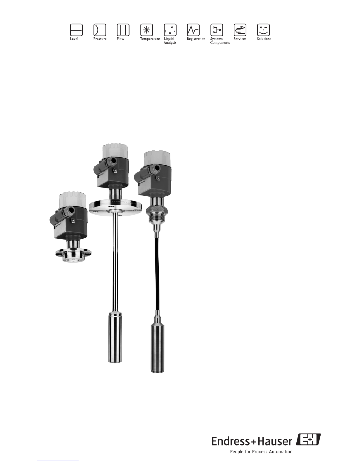
Endress+Hauser Deltapilot S DB50, Deltapilot S DB50L, Deltapilot S DB51, Deltapilot S DB52, Deltapilot S DB53 Technical Information
Page 1
TI257P/00/en
71034474
Technical Information
Deltapilot S DB50/50L/51/52/53
Hydrostatic Level Measurement
Pressure sensor with CONTITE
TM
measuring cell;
waterproof, climatic-proofed, long-term stability; for food, fresh
water and wastewater, chemical and pharmaceutical products
Application
The devices in the Deltapilot S product family are used
for continuous level measurement in all liquid and pastelike media. They are used in both the chemical,
pharmaceutical and food industry as well as in the water
and wastewater sector.
Switching units perfectly in line with the application:
• Determine the level, volume, differential pressure,
density and product weight
• Control limit contacts
• Integrate the measuring point in various automation
systems.
Your benefits
• Hermetically sealed CONTITE
TM
measuring cell:
– Climatic-proofed and with high long-term stability
– Maximum linearity (better than 0.1 % of the set
measuring range)
– Minimum temperature effects
(better than 0.1%/10 K).
• Compact, rod or cable versions available
• Separate mounting of housing and electronic insert
(IP 68 protection at the measuring point)
• Easy and comfortable operation:
– Onsite with display and operating module
– Operation via communication
• Replaceable electronic inserts:
– 4 to 20 mA HART
– PROFIBUS PA
– FOUNDATION Fieldbus
– Analog output
–PFM
Page 2

Deltapilot S
2
Endress+Hauser
Table of contents
Function and system design. . . . . . . . . . . . . . . . . . . . . 4
Device selection . . . . . . . . . . . . . . . . . . . . . . . . . . . . . . . . . . . . . . 4
Measuring principle . . . . . . . . . . . . . . . . . . . . . . . . . . . . . . . . . . . 6
Communication protocol . . . . . . . . . . . . . . . . . . . . . . . . . . . . . . 9
Measuring system . . . . . . . . . . . . . . . . . . . . . . . . . . . . . . . . . . . . . 9
Human interface . . . . . . . . . . . . . . . . . . . . . . . . . . . . 10
Onsite display (optional) . . . . . . . . . . . . . . . . . . . . . . . . . . . . . . . 10
Operating elements . . . . . . . . . . . . . . . . . . . . . . . . . . . . . . . . . . 11
DAT module . . . . . . . . . . . . . . . . . . . . . . . . . . . . . . . . . . . . . . . 11
Handheld terminals – HART . . . . . . . . . . . . . . . . . . . . . . . . . . . 11
FieldCare – HART, PROFIBUS PA . . . . . . . . . . . . . . . . . . . . . . . 12
Commuwin II – HART, PROFIBUS PA . . . . . . . . . . . . . . . . . . . . 12
Remote operation – FOUNDATION Fieldbus . . . . . . . . . . . . . . . 12
Input (measured variable) . . . . . . . . . . . . . . . . . . . . . 12
Measured variable . . . . . . . . . . . . . . . . . . . . . . . . . . . . . . . . . . . 12
Measuring range . . . . . . . . . . . . . . . . . . . . . . . . . . . . . . . . . . . . 12
Explanation of terms . . . . . . . . . . . . . . . . . . . . . . . . . . . . . . . . . 13
Output . . . . . . . . . . . . . . . . . . . . . . . . . . . . . . . . . . . . 14
Output signal . . . . . . . . . . . . . . . . . . . . . . . . . . . . . . . . . . . . . . . 14
Signal on alarm . . . . . . . . . . . . . . . . . . . . . . . . . . . . . . . . . . . . . 14
Load . . . . . . . . . . . . . . . . . . . . . . . . . . . . . . . . . . . . . . . . . . . . . 14
Sensitivity, PFM –FEB17(P) . . . . . . . . . . . . . . . . . . . . . . . . . . . . 14
Damping . . . . . . . . . . . . . . . . . . . . . . . . . . . . . . . . . . . . . . . . . . 14
Power supply . . . . . . . . . . . . . . . . . . . . . . . . . . . . . . . 15
Electrical connection . . . . . . . . . . . . . . . . . . . . . . . . . . . . . . . . 15
Supply voltage . . . . . . . . . . . . . . . . . . . . . . . . . . . . . . . . . . . . . . 16
Current consumption . . . . . . . . . . . . . . . . . . . . . . . . . . . . . . . . . 16
Switch-on current . . . . . . . . . . . . . . . . . . . . . . . . . . . . . . . . . . . 16
Cable entry . . . . . . . . . . . . . . . . . . . . . . . . . . . . . . . . . . . . . . . . 16
Cable specification . . . . . . . . . . . . . . . . . . . . . . . . . . . . . . . . . . . 16
Residual ripple . . . . . . . . . . . . . . . . . . . . . . . . . . . . . . . . . . . . . . 17
Performance characteristics. . . . . . . . . . . . . . . . . . . . 17
Reference operating conditions . . . . . . . . . . . . . . . . . . . . . . . . . . 17
Position during calibration . . . . . . . . . . . . . . . . . . . . . . . . . . . . 17
Zero-point increase . . . . . . . . . . . . . . . . . . . . . . . . . . . . . . . . . . 17
Long-term stability . . . . . . . . . . . . . . . . . . . . . . . . . . . . . . . . . . . 17
Linearity . . . . . . . . . . . . . . . . . . . . . . . . . . . . . . . . . . . . . . . . . . . 17
Hysteresis . . . . . . . . . . . . . . . . . . . . . . . . . . . . . . . . . . . . . . . . . . 17
Influence of ambient temperature . . . . . . . . . . . . . . . . . . . . . . . 17
Influence of medium temperature . . . . . . . . . . . . . . . . . . . . . . . 17
Operating conditions (installation) . . . . . . . . . . . . . . 18
Installation instructions for compact version
DB50, DB50A, DB50L, DB50S . . . . . . . . . . . . . . . . . . . . . . . . . 18
Installation instructions for rod and cable versions
DB51(A), DB52(A) and DB53(A) . . . . . . . . . . . . . . . . . . . . . . . 18
Supplementary installation instructions . . . . . . . . . . . . . . . . . . . . 18
Housing adapter with mounting bracket for humid, damp and
difficult-to-access mounting locations . . . . . . . . . . . . . . . . . . . . 19
Special measuring cells for substances with hydrogen formation 19
Special measuring cell for acids, alkalis or sea water . . . . . . . . . . 19
Operating conditions (environment) . . . . . . . . . . . . . 20
Ambient temperature range . . . . . . . . . . . . . . . . . . . . . . . . . . . . 20
Ambient temperature limits . . . . . . . . . . . . . . . . . . . . . . . . . . . . 20
Storage temperature range . . . . . . . . . . . . . . . . . . . . . . . . . . . . . 20
Vibration resistance . . . . . . . . . . . . . . . . . . . . . . . . . . . . . . . . . . 20
Degree of protection . . . . . . . . . . . . . . . . . . . . . . . . . . . . . . . . . 20
Electromagnetic compatibility (EMC) . . . . . . . . . . . . . . . . . . . . 20
Overvoltage protection . . . . . . . . . . . . . . . . . . . . . . . . . . . . . . . . 20
Operating conditions (process) . . . . . . . . . . . . . . . . . 21
Process temperature range . . . . . . . . . . . . . . . . . . . . . . . . . . . . . 21
Process temperature limits . . . . . . . . . . . . . . . . . . . . . . . . . . . . . 21
Process pressure limits . . . . . . . . . . . . . . . . . . . . . . . . . . . . . . . . 21
Mechanical construction . . . . . . . . . . . . . . . . . . . . . . 21
Dimensions of housing . . . . . . . . . . . . . . . . . . . . . . . . . . . . . . . 21
Process connections DB50 and DB50A (compact version) . . . . . 22
Process connection DB50L and DB50S (food version) . . . . . . . . 25
Process connections DB51 and DB51A (rod/pipe version) . . . . 27
Dimensions of Deltapilot S DB52 and DB52A (cable version) . . 28
Dimensions of Deltapilot S DB53 and DB53A
(suspension clamp and mounting bracket) . . . . . . . . . . . . . . . . 30
Dimensions of connecting cable with
housing adapter and mounting bracket . . . . . . . . . . . . . . . . . . . 31
Weight . . . . . . . . . . . . . . . . . . . . . . . . . . . . . . . . . . . . . . . . . . . 32
Material . . . . . . . . . . . . . . . . . . . . . . . . . . . . . . . . . . . . . . . . . . . 34
Certificates and approvals . . . . . . . . . . . . . . . . . . . . . 35
CE mark . . . . . . . . . . . . . . . . . . . . . . . . . . . . . . . . . . . . . . . . . . 35
Ex approvals . . . . . . . . . . . . . . . . . . . . . . . . . . . . . . . . . . . . . . 35
Overfill protection . . . . . . . . . . . . . . . . . . . . . . . . . . . . . . . . . . . 35
Seismic test . . . . . . . . . . . . . . . . . . . . . . . . . . . . . . . . . . . . . . . . 35
Marine approval . . . . . . . . . . . . . . . . . . . . . . . . . . . . . . . . . . . . . 35
Standards and guidelines . . . . . . . . . . . . . . . . . . . . . . . . . . . . . 35
Ordering information . . . . . . . . . . . . . . . . . . . . . . . . . 36
DB50 – compact version . . . . . . . . . . . . . . . . . . . . . . . . . . . . . . 36
DB50L – compact version for hygienic applications . . . . . . . . . . . 38
DB51 – rod version . . . . . . . . . . . . . . . . . . . . . . . . . . . . . . . . . . 40
DB52 – cable version with process connection . . . . . . . . . . . . . . 42
DB53 – cable version with suspension clamp . . . . . . . . . . . . . . . 44
DB50A – compact version . . . . . . . . . . . . . . . . . . . . . . . . . . . . 46
DB50S – compact version for hygienic applications . . . . . . . . . . 48
DB51A – rod version . . . . . . . . . . . . . . . . . . . . . . . . . . . . . . . . . 50
DB52A – cable version with process connection . . . . . . . . . . . . 52
DB53A – cable version with suspension clamp . . . . . . . . . . . . . 54
Page 3

Endress+Hauser
3
Deltapilot S
Accessories . . . . . . . . . . . . . . . . . . . . . . . . . . . . . . . . 56
Display and operating module FHB20 . . . . . . . . . . . . . . . . . . . . 56
Cover with sight glass (high cover) . . . . . . . . . . . . . . . . . . . . . . 56
Housing adapter with mounting bracket for humid, damp and
difficult-to-access mounting locations . . . . . . . . . . . . . . . . . . . 56
Mounting bracket . . . . . . . . . . . . . . . . . . . . . . . . . . . . . . . . . . . 56
Extension cable shortening kit . . . . . . . . . . . . . . . . . . . . . . . . . 56
Suspension clamp . . . . . . . . . . . . . . . . . . . . . . . . . . . . . . . . . . . 56
Protective cover . . . . . . . . . . . . . . . . . . . . . . . . . . . . . . . . . . . . 57
Welding flanges . . . . . . . . . . . . . . . . . . . . . . . . . . . . . . . . . . . . . 57
Welding neck adapter for universal process adapter . . . . . . . . . . 58
Welding neck adapter thread ISO G 1 1/2 . . . . . . . . . . . . . . . . . 58
Adapter . . . . . . . . . . . . . . . . . . . . . . . . . . . . . . . . . . . . . . . . . . . 58
Documentation . . . . . . . . . . . . . . . . . . . . . . . . . . . . . 59
Field of Activities . . . . . . . . . . . . . . . . . . . . . . . . . . . . . . . . . . . 59
Technical Information on switching unit . . . . . . . . . . . . . . . . . 59
Operating Instructions . . . . . . . . . . . . . . . . . . . . . . . . . . . . . . . . 59
Safety Instructions . . . . . . . . . . . . . . . . . . . . . . . . . . . . . . . . . . . 59
Installation Drawings/Control Drawings . . . . . . . . . . . . . . . . . . 59
Overfill protection . . . . . . . . . . . . . . . . . . . . . . . . . . . . . . . . . . . 59
Page 4
Deltapilot S
4 Endress+Hauser
Function and system design
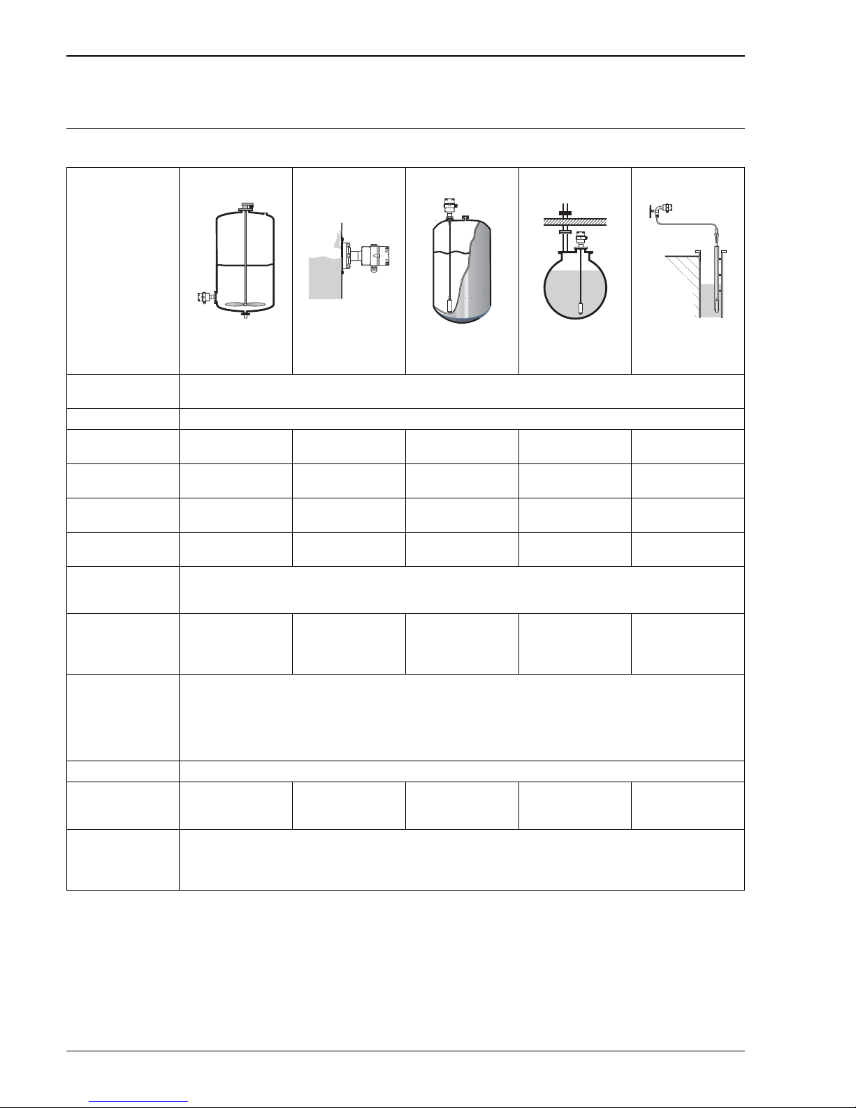
Device selection
Deltapilot S –
product family
DB50/DB50A
P01-DB5xxxxx-14-xx-xx-xx-001
Compact version
DB50L/DB50S
P01-DB5xxxxx-14-xx-xx-xx-002
Compact version as
hygienic version
DB51/DB51A
P01-DB5xxxxx-14-xx-xx-xx-003
Rod version
DB52/DB52A
P01-DB5xxxxx-14-xx-xx-xx-004
Cable version
DB53/DB53A
P01-DB5xxxxx-14-xx-xx-xx-005
Cable version with
suspension clamp
Field of application – Level measurement
– Differential pressure measurement (derived from level via switching unit)
Industries Food, pharmaceutical, environment (fresh water and wastewater), chemical
Process connections – Thread
–Flanges
– Flush-mounted
hygienic connections
–Thread
– Flanges
–Thread
–Flanges
– Suspension clamp
Process connection
material
– AISI 316L
– Alloy C4
– AISI 316L – AISI 316L
– Alloy C4
– AISI 316L
– Alloy C4
– AISI 316L with
plastic
Rod (pipe)/
extension cable material
— — – AISI 316L
– Alloy C4
–FEP
–PE
–FEP
–PE
Pipe/extension cable
length
— — 400 to 4000 mm
(16 to 160 inch)
0.5 to 200 m
(20 to 7874 inch)
1
0.5 to 200 m
(20 to 7874 inch)
1
Measuring ranges – from –100 to +100 mbar to –900 to +10000 mbar
– US version: from –1.5 to +1.5 psi to –13 to 150 psi
– Max. turn down: 10:1
Process temperature –10 to +100°C
(+14 to +212°F)
–10 to +100°C
(+14 to +212°F),
+135°C (+275°F)
for 30 minutes
–10 to +80°C
(+14 to +176°F)
–10 to +80°C
(+14 to +176°F)
–10 to +80°C
(+14 to 176°F)
Supply voltage – Analog 0.2 to 1.2 mA: 15 to 20 V DC
– PFM: 14 to 16 V DC; EEx ia: 14 to 19.2 V DC
– 4 to 20 mA HART: 11.5 to 30 V DC; EEx ia: 11.5 to 30 V DC
– PROFIBUS PA , version without overvoltage protection: 9 to 32 V DC, EEx ia: 9 to 24 V DC
Version with overvoltage protection: 9.6 to 32 V DC; EEx ia: 9 to 24 V DC
– FOUNDATION Fieldbus: 9 to 32 V DC; EEx ia: 9 to 24 V DC
Output 0.2 to 1.2 mA, analog, PFM, 4 to 20 mA with superimposed HART protocol, PROFIBUS PA or FOUNDATION Fieldbus
Options – 3.1 Inspection
certificate
– Separate housing
– 3.1 Inspection
certificate
–Separate housing
– Separate housing – Separate housing —
Specialties – Absolutely resistant to condensate thanks to hermetically sealed CONTITE
TM
cell
– Stainless steel version (AISI 316L) for hygienic requirements as well as aluminum and polyester housing versions
– 3A and EHEDG approval
– Maximum flexibility thanks to modular design
1) EExia, FM IS, CSA IS: 0.5 to 100 m (20 to 3937 inch)
Page 5

Deltapilot S
Endress+Hauser 5
DB50(A), DB51(A), DB52(A) universal usage
• Modular probe program for optimum process adaptation
• DB50(A) compact version: installation in the tank from below or from the side
• DB51(A)/DB52(A) rod and cable extension: installation from above, i.e. easy to equip and retrofit buried
tanks, no additional opening in the tank floor
DB50L/DB50S optimized for the food and pharmaceutical industry
• All typical flush-mounted process connections can be supplied
• Welding flanges
• Stainless steel housing
• All food process connections are gap-free and can be cleaned without any residue left, e.g. CIP cleaning
• USDA/H1 approved transfer liquid as per FDA guidelines
• 3A or EHEDG approvals
P01-DB5xxxxx-12-xx-xx-xx-004
DB53(A) for the water and wastewater industry
• The housing with the electronic insert is mounted outside shafts and tanks in such a way that it is protected
from flooding. The extension cable is secured with a suspension clamp.
• Electronic inserts with an integrated surge arrester provide protection against overvoltage if lightning strikes.
• The stainless steel measuring cell tube (AISI 316L) and the Alloy measuring diaphragm allow use in
aggressive media such as wastewater for example.
• Extension cable up to 200 m in length (up to 100 m in Ex-areas) without strain relief.
• Special measuring cell with gold-rhodium coating for applications in which severe hydrogen formation can
occur (e.g. digested sludge); see also Page 19.
• Special measuring cell with gold-platinum coating for acids, alkalis or sea water; see also Page 19.
74 - 02
®
Page 6
Deltapilot S
6 Endress+Hauser
Measuring principle
P01-DB5xxxxx-15-xx-xx-xx-003
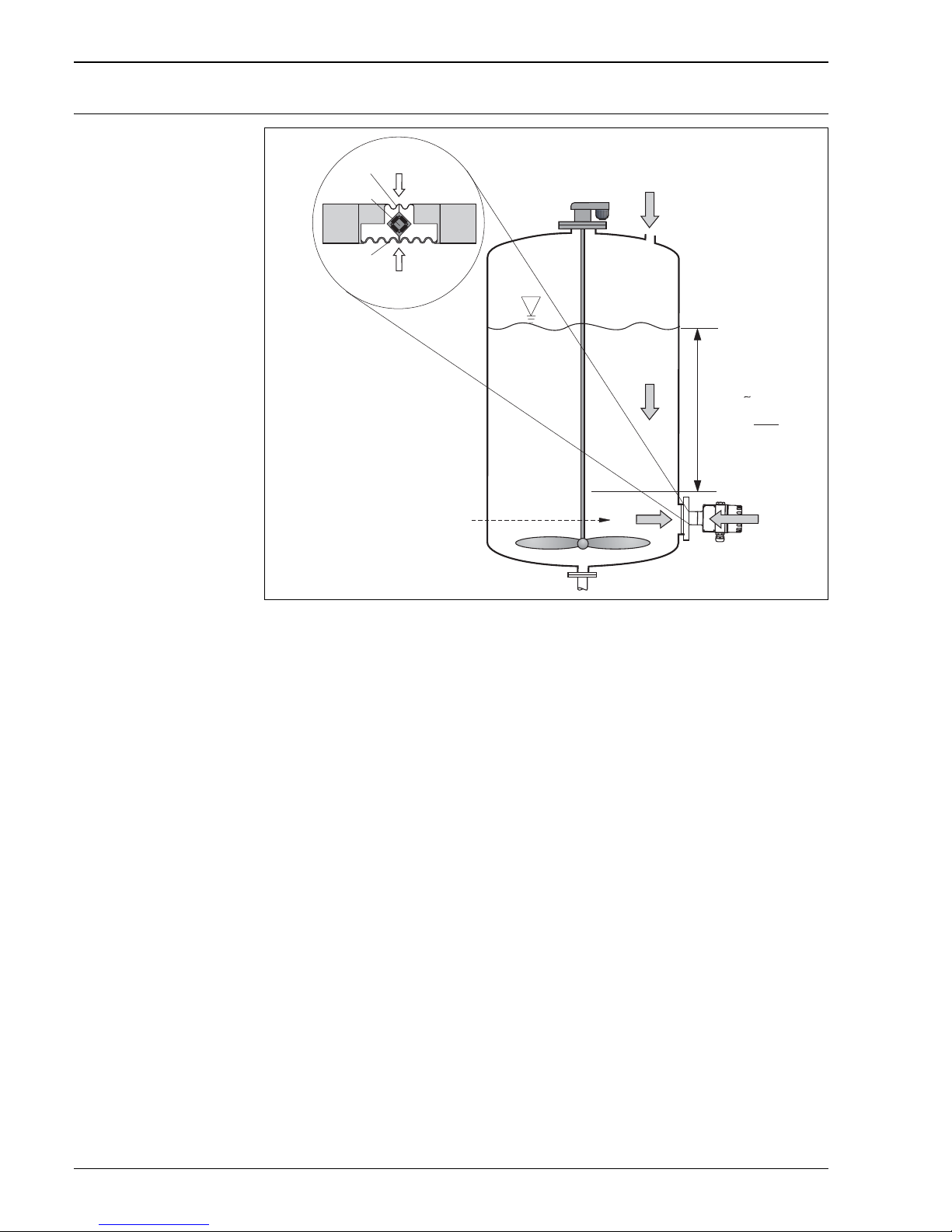
Deltapilot S hydrostatic level measurement and measuring principle
1 Measuring diaphragm
2 Measuring element
3 Process diaphragm (separating diaphragm)
g Gravitational acceleration
h Level height
p
tot
Total pressure = hydrostatic pressure + atmospheric pressure
p
atm
Atmospheric pressure
p
hydr.
Hydrostatic pressure
p
meas
Measured pressure in the measuring cell = hydrostatic pressure
ρ Density of fluid
Due to its weight, a liquid column creates hydrostatic pressure. If the density is constant, the hydrostatic
pressure depends solely on the height h of the liquid column.
The CONTITE™ measuring cell which works on the principle of the gauge pressure sensor constitutes the core
of Deltapilot S. In contrast to conventional gauge pressure sensors, the precision measuring element (2) in the
CONTITE™ measuring cell is absolutely protected between the process diaphragm (3) and the measuring
diaphragm (1). Thanks to this hermetic sealing of the measuring element, the CONTITE™ measuring cell is
absolutely insensitive to condensate, condensation and aggressive gases. The pressure applied is transferred
from the process diaphragm to the measuring element by means of an oil without any loss in pressure.
Two temperature sensors are arranged between the process diaphragm and measuring element which measure
the distribution of temperature in the cell. The electronics can compensate any measuring errors resulting from
fluctuations in temperature with these temperature measured values.
h
h =
p
ρ · g
hp
hydr.
p
+
p
atm
p =
➀
➂
➁
p
atm
hydr.
p
p
atm
p
atm
ges
p
hydr.
p
+
p
atm
=
ges
p
)
hydr.
p
+
(p
atm
p
atm
p
mess
=
–
p
ges
p
atm
p
mess
=
–
p
ges
p
atm
p
mess
=
–
Page 7
Deltapilot S
Endress+Hauser 7
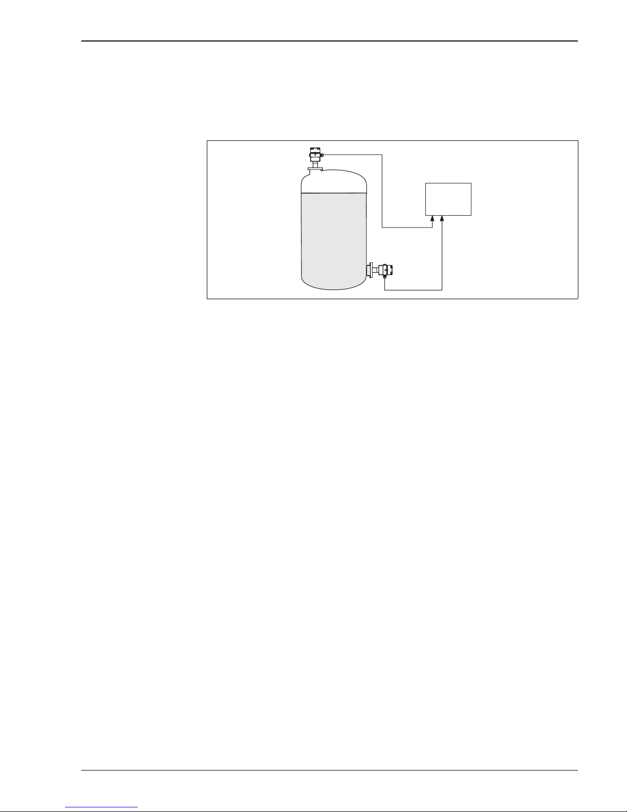
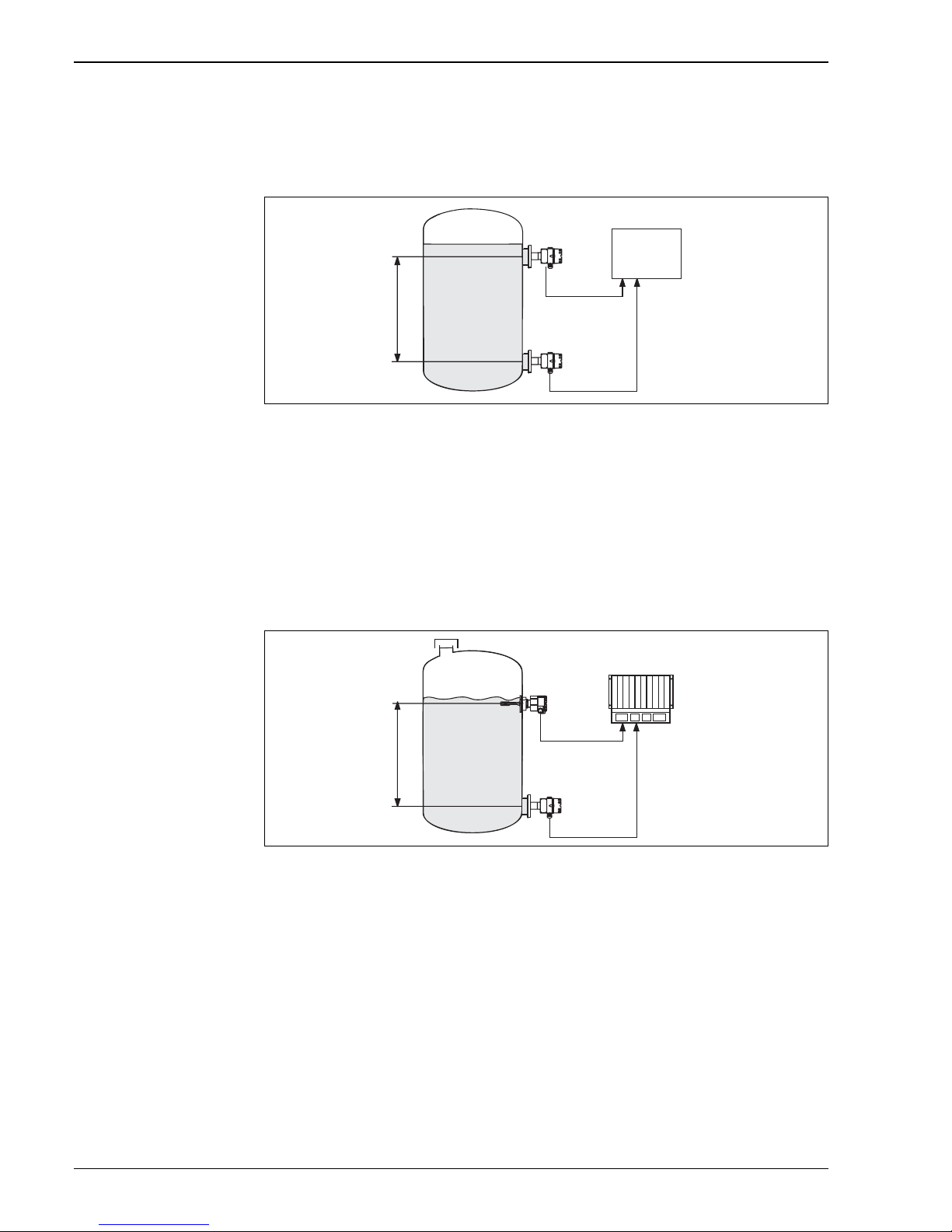
Level measurement in closed tanks with pressure overlay
You can determine the differential pressure in tanks with pressure overlay using two Deltapilot S probes. The
pressure measured values of the two probes are sent to a signal processing unit such as Endress+Hauser RMA
or a PLC. The signal processing unit or PLC determines the difference in pressure and uses this to calculate the
level and the density where necessary.
P01-DB5xxxxx-15-xx-xx-xx-007
Level measurement in a closed tank with pressure overlay
1 Probe 1 measures the total pressure (hydrostatic pressure and top pressure)
2 Probe 2 measures the top pressure
3 The signal processing unit determines the difference in pressure and uses this to calculate the level
Note!
• When selecting the Deltapilot S probes, make sure you select large enough measuring ranges
(→ see example).
• The measuring diaphragm of probe 2 must not be flooded. This generates additional hydrostatic pressure
which distorts the measurement.
• The ratio of hydrostatic pressure to top pressure should be max. 1:6.
Example:
• Max. hydrostatic pressure = 600 mbar
• Max. top pressure (probe 2) = 300 mbar
• Max. total pressure, measured with probe 1 = 300 mbar + 600 mbar = 900 mbar
⇒ Measuring cell to be selected: 0 to 1200 mbar
• Max. pressure, measured with probe 2: 300 mbar
⇒ Measuring cell to be selected: 0 to 400 mbar
➁
➀
➂
Page 8
Deltapilot S
8 Endress+Hauser
Density measurement
You can measure the density in tanks with pressure overlay using two Deltapilot S probes and a signal
processing unit or a PLC. The signal processing unit or the PLC calculates the density from the known distance
Δh between the two probes and the two measured values p
1
and p2.
P01-DB5xxxxx-15-xx-xx-xx-005
Level measurement in a closed tank with pressure overlay
1 Deltapilot S determines pressure measured value p
1
2 Deltapilot S determines pressure measured value p
2
3 Signal processing unit determines the density from the two measured values p1 and p2 and the distance Δh.
Level measurement with automatic density correction (with changing media in the tank)
Level measurement with automatic density correction is possible in conjunction with a limit switch such as
Liquiphant and a PLC. The limit switch always switches at the same level. In the switch point, the signal
processing unit determines the corrected density from the pressure of the Deltapilot S probe currently
measured and the known distance between Deltapilot S and the limit switch. The signal processing unit then
calculates the level from the new density and the measured pressure from the Deltapilot S probe.
P01-DB5xxxxx-15-xx-xx-xx-006
Level measurement with automatic density correction
1 Deltapilot S
2 Liquiphant
3PLC
p
2
p
1
Δh
➁
➀
➂
Δh
➁
➀
➂
Page 9

Deltapilot S
Endress+Hauser 9
Communication protocol • 4 to 20 mA with HART communication protocol
•PROFIBUS PA
– The Endress+Hauser Deltapilot S devices meet the FISCO model requirements.
– Due to the low current consumption of 10 ± 1 mA, the following can be operated at one bus segment
with installation as per FISCO:
– Up to 9 Deltapilot S for EEx ia, CSA IS and FM IS applications
– Up to 32 Deltapilot S for all other applications, e.g. in non-hazardous areas, EEx nA, etc.
Further information on PROFIBUS PA can be found in Operating Instructions BA034S "PROFIBUS DP/PA:
Guidelines for planning and commissioning" and in the PNO guideline.
• FOUNDATION Fieldbus
– The Endress+Hauser Deltapilot S devices meet the FISCO model requirements.
– Due to the low current consumption of 11 ± 1 mA, the following can be operated at one bus segment
with installation as per FISCO:
– Up to 9 Deltapilot S for EEx ia, CSA IS and FM IS applications
– Up to 32 Deltapilot S for all other applications, e.g. in non-hazardous areas, EEx nA, etc.
Further information on FOUNDATION Fieldbus such as bus system component requirements are provided
in Operating Instructions BA013S "FOUNDATION Fieldbus Overview".
Measuring system Measuring system with 0.2 to 1.2 mA analog – FEB11(P)
The electronic insert returns a current signal of 0.2 to 1.2 mA that is in proportion to the pressure. The
FMC420 silometer provides voltage to the electronic insert and evaluates the current signal that is in proportion
to the level. The standardized signals of 0 to 10 V and 4 to 20 mA (0 to 20 mA) are then available at the output
of the silometer. → See also Technical Information TI077F and Operating Instructions BA179F.
Measuring system with PFM – FEB17(P)
The electronic insert returns a pulse-frequency-modulated signal of 200 to 1200 Hz. The evaluation and
operating unit Prolevel FMB662 provides power to the electronic insert and converts the PFM signal of the
probe to a standardized current or voltage signal. → See also Technical Information TI234F and Operating
Instructions BA144F.
Measuring system with 4 to 20 mA HART – FEB22(P)
HART is a field-tested industry standard accepted worldwide. In HART technology, the 4 to 20 mA analog
transmission and the digital communication take place simultaneously via the same wire pair. The 4 to 20 mA
analog signal is used for rapid measured value transmission. The digital HART signal allows device data to be
read and written, e.g. for diagnosis and maintenance information.
Measuring system with PROFIBUS PA – FEB24(P)
PROFIBUS PA is an open fieldbus standard. It allows multiple sensors and actuators to be connected, even in
Ex-areas. By means of PROFIBUS PA, energy is supplied to the devices with two-wire technology and the
process information is transmitted digitally from the sensor.
Further information on PROFIBUS PA, such as bus system component requirements, can be found in Operating
Instructions BA034S "PROFIBUS DP/PA: Guidelines for planning and commissioning" and in the PNO
guideline.
Measuring system with FOUNDATION Fieldbus – FEB26
FOUNDATION Fieldbus is an open fieldbus standard. It allows multiple sensors and actuators to be connected,
even in Ex-areas. By means of FOUNDATION Fieldbus, energy is supplied to the devices with two-wire
technology and the process information is transmitted digitally from the sensor.
Further information on FOUNDATION Fieldbus such as bus system component requirements are provided in
Operating Instructions BA013S "FOUNDATION Fieldbus Overview".
Page 10
Deltapilot S
10 Endress+Hauser
Human interface
Onsite display (optional) The FHB20 display and operating module is available as an option for the following electronic inserts. → See
also Page 37, feature 70 "Electronic insert":
• 4 to 20 mA HART – FEB22(P)
• PROFIBUS PA – FEB24(P)
• FOUNDATION Fieldbus – FEB26
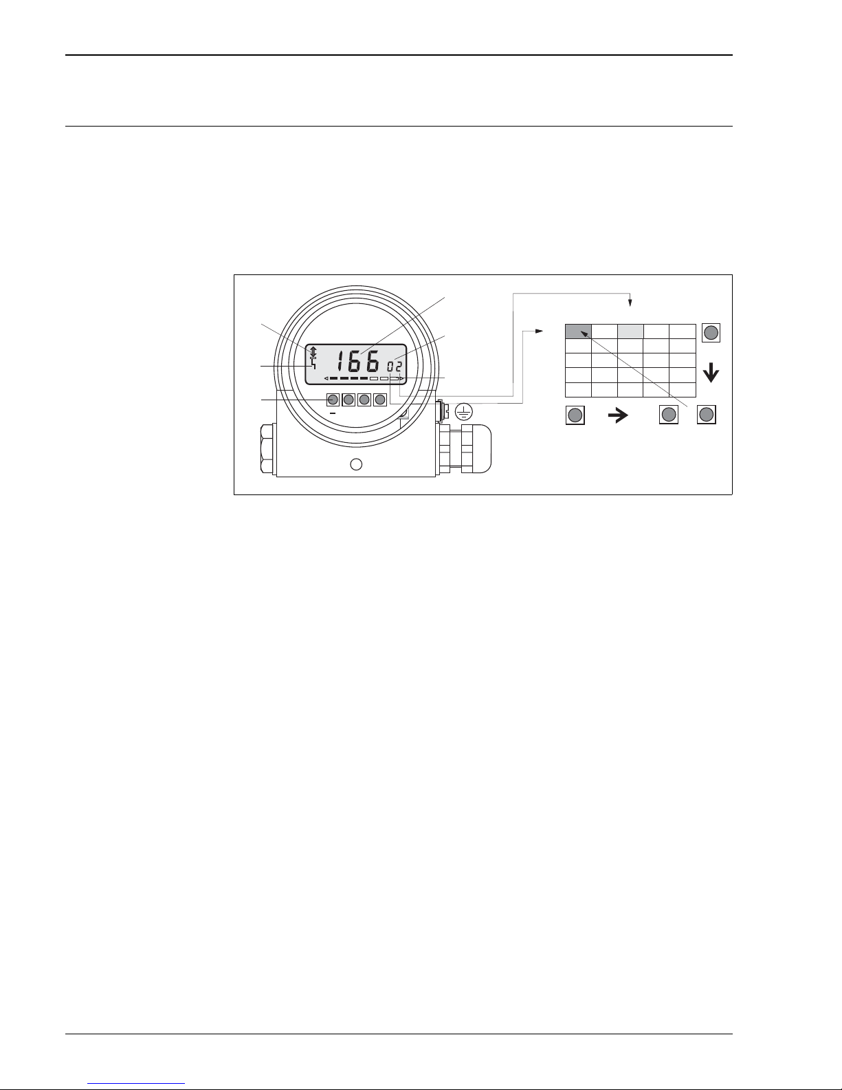
The parameters are illustrated in a 10 x 10 matrix (→ see Figure, No. p). With the display module, you can
access every parameter directly at the place of measurement. Dry calibration, linearization and operation
enabling and disabling are possible without any further tools.
P01-DB5xxxxx-07-xx-xx-xx-001
User interface of the electronic insert with the FHB20 display and operating module
1 4 1/2-digit display of measured values and parameters
2 Current matrix position
3 Bar graph of the measured value
4 Operating matrix
5Operating keys
6 Signal for reporting an error
7 Communication signal, lights up when operating using the handheld terminal or via remote operation
➀
➁
➂
➃
➄
➅
➆
V
H
+
V H
V
H
V H
+
V0
V1
V2
V3
V4
H0 H1 H2 H3 H4
Page 11
Deltapilot S
Endress+Hauser 11
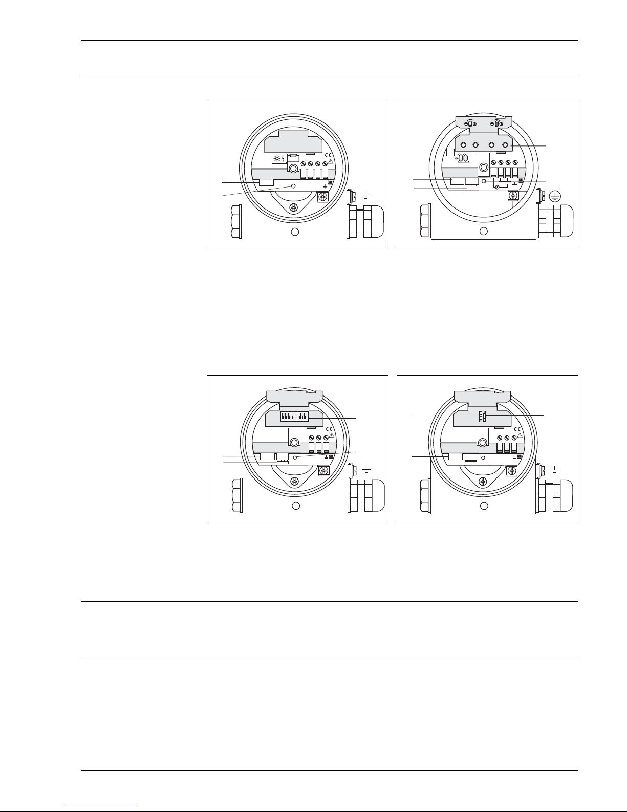
Operating elements Operating keys and elements on the electronic insert
DAT module All the specific data of the measuring cell are saved in the DAT module. When the device is switched on, these
data are read out of the DAT module and into the electronic insert memory.
The DAT module can be ordered as a spare part (order number: 542585-0000). However, the measuring cell
number must be stated when ordering.
Handheld terminals – HART With the handheld terminal Universal-HART-Communicator DXR275 or DXR375, all the parameters can be
configured anywhere along the 4 to 20 mA line via menu operation.
P01-DB5xxxxx-19-x x-xx-xx-006
Electronic insert FEB11(P) – 0.2 to 1.2 mA and
electronic insert FEB17(P) – PFM
1 Red LED to indicate a fault
2 Slot for the DAT module
P01-DB5xxxxx-19-xx-xx-xx-003
Electronic insert FEB22(P) – 4 to 20 mA HART
1 Operating keys for empty and full calibration,
calibration with partially full tanks,
lock/unlock operation and reset
2 Green LED flashes when accepting the value for
empty and full calibration, during a reset and if
operation is locked or unlocked
3 Slot for optional FHB20 display and operating
module
4 Slot for the DAT module
P01-DB5xxxxx-19-x x-xx-xx-004
Electronic insert FEB24(P) – PROFIBUS PA
1 DIP switches for bus address
2 Red LED to indicate a warning or a fault
3 Slot for optional FHB20 display and operating
module
4 Slot for the DAT module
P01-DB5xxxxx-19-xx-xx-xx-005
Electronic insert FEB26 – FOUNDATION Fieldbus
1 DIP switch to lock/unlock operation
2 Slot for optional FHB20 display and operating
module
3 Slot for the DAT module
4 DIP switch for switching simulation mode on/off
➀
➁
DAT-Modul
RED
+
–
S
123
4
FEB
xx
➀
➁
➂
➃
FHB 20
GREEN
DAT-Modul
+
+
1
2
3
4…20 mA
–
4
–
FEB
22(P)
PA– PA +
Alarm LED
DAT-Modul
FHB 20
➀
➁
➂
➃
1234567
8
FEB
24(P)
➀
➁
➂
➃
FF– FF+
Alarm LED
DAT-Modul
FHB 20
FEB
26
SIMMOD WPM
Page 12

Deltapilot S
12 Endress+Hauser
FieldCare –
HART, PROFIBUS PA
FieldCare is an Endress+Hauser asset management tool based on FDT technology. With FieldCare, you can
configure all Endress+Hauser devices as well as devices from other manufacturers that support the FDT
standard. The following operating systems are supported: WinNT4.0, Win2000 and Windows XP.
FieldCare supports the following functions:
• Configuration of transmitters in offline and online operation
• Loading and saving device data (upload/download)
• Documentation of the measuring point
Commuwin II –
HART, PROFIBUS PA
Commuwin II is a graphically supported operating program for intelligent measuring devices with the
communication protocols HART and PROFIBUS PA. The following operating systems are supported:
Win 3.1/3.11, Win 95, Win 98, WinNT4.0 and Win2000.
Commuwin II supports the following functions:
• Configuration of measuring devices in online operation via matrix operation
• Loading and saving device data (upload/download)
• Visualization of measured values and limit values
• Presentation and recording of measured values with a line recorder.
Connection option:
• HART via Commubox FXA191 with the serial interface RS 232 C of a computer or via Commubox FXA195
with the USB interface of a computer
• PROFIBUS PA via segment coupler and PROFIBUS interface card
Remote operation –
FOUNDATION Fieldbus
An FF configuration program is required to integrate a device with "FOUNDATION Fieldbus signal" into an FF
network or to set the FF-specific parameters. Please contact your local Endress+Hauser Sales Center for more
information.
Input (measured variable)
Measured variable Hydrostatic pressure
Measuring range
Measuring range Measuring limit Recommended
span
Overload Vacuum resistance Version in the
order code
1
lower (LRL) upper (URL) min./max.
[bar] [bar] [bar] bar
abs
bar
0 to +100 mbar 0 +0.1 0.025/0.1 8 –0.1 BA
0 to +400 mbar 0 +0.4 0.04/0.4 8 –0.4 BB
0 to +1200 mbar 0 +1.2 0.12/1.2 24 –0.9 BC
0 to +4 bar 0 +4 0.4/4 24 –0.9 BD
0 to +10 bar 0 +10 1/10 40 –0.9 BE
–100 to +100 mbar –0.1 +0.1 0.025/0.1 8 –0.1 DA
–400 to +400 mbar –0.4 +0.4 0.04/0.4 8 –0.4 DB
–900 to +1200 mbar –0.9 +1.2 0.12/1.2 24 –0.9 DC
–900 to +4000 mbar –0.9 +4 0.4/4 24 –0.9 DD
–0.9 to +10 bar –0.9 +10 1/10 40 –0.9 DE
1) See also Page 36 ff, "Ordering information" chapter, feature 40 "Measuring range"
Page 13
Deltapilot S
Endress+Hauser 13
Explanation of terms • A turn down of TD = 10:1 is possible with the following electronic inserts:
– 4 to 20 mA HART – FEB22(P)
– PROFIBUS PA – FEB24(P)
– FOUNDATION Fieldbus – FEB26
Turn down is possible via the signal processing units for electronic inserts 0.2 to 1.2 mA analog – FEB11(P)
and PFM – FEB17(P). → See "Function and system design" chapter, "Measuring device" section.
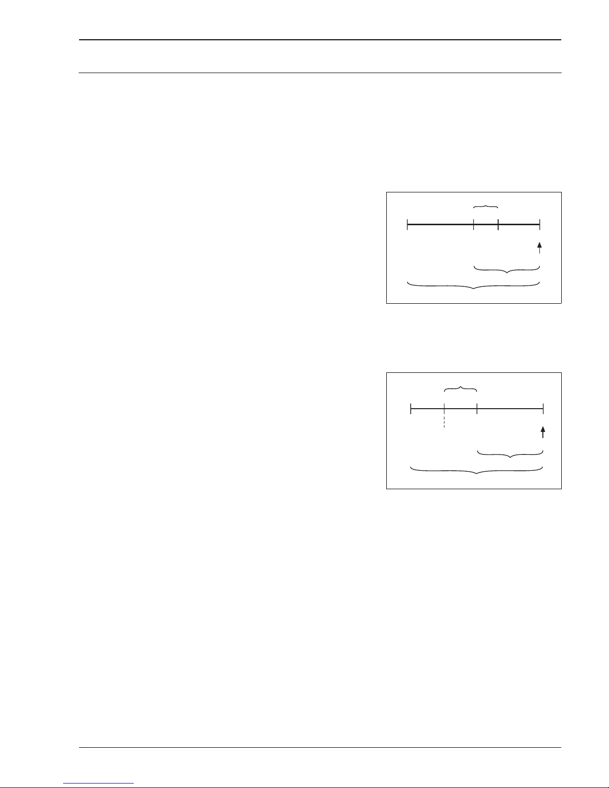
Explanation of terms: turn down (TD),
set span and span based on zero point
Case 1:
• ⏐Lower range value (LRV)⏐ ≤ ⏐Upper range value
(URV)⏐
Example:
• Lower range value (LRV) = 0 mbar
• Upper range value (URV) = 40 mbar
• Nominal value (URL) = 400 mbar
Turn down:
• Nominal value /⏐upper range value (URV)⏐=
400 mbar/40 mbar
TD = 10:1
Set span:
• Upper range value (URV) – lower range value (LRV) =
40 mbar – 0 mbar
Set span = 40 mbar
This span is based on the zero point.
P01-DBxxxxxx-05-xx-xx-xx-001
Example: 400 mbar measuring cell
Case 2:
• ⏐Lower range value (LRV)⏐ ≥ ⏐Upper range value
(URV)⏐
Example:
• Lower range value (LRV) = –200 mbar
• Upper range value (URV) = 0 bar
• Nominal value (URL) = 400 mbar
Turn down:
• Nominal value /⏐lower range value (LRV)⏐
= 400 mbar/200 mbar
TD 2:1
Set span:
• Upper range value (URV) – lower range value (LRV) =
0 mbar – (–200 mbar)
Set span = 200 mbar
This span is based on the zero point.
P01-DBxxxxxx-05-xx-xx-xx-002
Example: 400 mbar measuring cell
1Set span
2 Span based on zero point
3 Nominal value i upper range limit (URL)
4 Nominal measuring range
5Sensor measuring range
LRL Lower range limit
URL Upper range limit
LRV Lower range value
URV Upper range value
–400 mbar
0
+400 mbar
40
LRL
LRV
URL
URV
➁➀
=
➂
➃
➄
–400 mbar
+400 mbar
LRV
URLURV
➂
0
LRL
–200 mbar
➁➀
=
➃
➄
Page 14
Deltapilot S
14 Endress+Hauser
Output
Output signal • 0.2 to 1.2 mA analog signal, 3-wire
• 200 to 1200 Hz PFM signal, 2-wire
–f0 = 200 Hz ± 5 Hz
– 100 mbar measuring range: f
0
= 200 Hz ± 10 Hz
• 4 to 20 mA with superimposed communication protocol HART, 2-wire
• Digital communication signal PROFIBUS PA (Profile 3.0), 2-wire
• Digital communication signal FOUNDATION Fieldbus, 2-wire
Signal on alarm • 0.2 to 1.2 mA analog: ≥ 1.5 mA
•PFM ≤ 20 Hz
• 4 to 20 mA HART
Options:
– Min. = 3.6 mA; onsite display: 0
– Max. = 22 mA (factory setting); onsite display: 1
– Hold: last measured value is held; onsite display: 2
•PROFIBUS PA:
– Options configurable in the Analog Input Block for the output signal:
Last Valid Out Value, FSafe Value (factory setting), Status bad
– Options configurable in the Transducer Block for the "Measured value" parameter and the onsite display:
Min. (onsite display: –19999), Max. (onsite display: +19999), Hold: last measured value is held
• FOUNDATION Fieldbus:
– Output signal: last measured value is held; status change from "Uncertain" or "Bad"
– Options configurable in the Transducer Block for the "Measured value" parameter and the onsite display:
Min. (onsite display: –19999), Max. (onsite display: +19999), Hold: last measured value is held
Load
Sensitivity, PFM –FEB17(P)
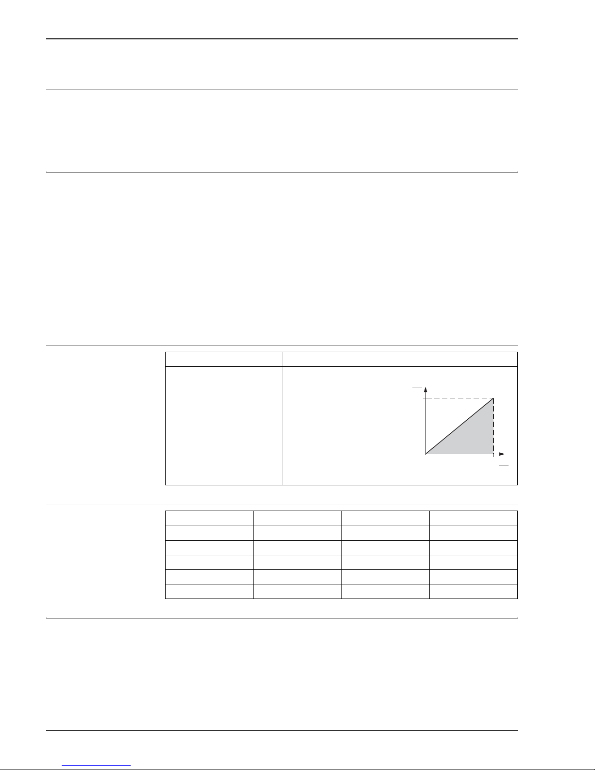
Damping • 0 to 99 s configurable via the FHB20 display and operating module, PC with operating program or handheld
terminal
• Factory setting: 0 s
0.1 to 1.2 mA analog PFM 4 to 20 mA HART
Max. 25 Ω/core Max. 25 Ω/core
P01-DB5xxxxx-05-xx-xx-xx-002
820
0
30
11.5 U
b
[V]
R
b
[]Ω
Measuring range Resolution Measuring range Resolution
0 to 100 mbar 10 Hz/mbar –100 to 100 mbar 5 Hz/mbar
0 to 400 mbar 2.5 Hz/mbar –400 to 400 mbar 1.25 Hz/mbar
0 to 1200 mbar 0.833 Hz/mbar –900 to 1200 mbar 0.476 Hz/mbar
0 to 4000 mbar 0.25 Hz/mbar –900 to 4000 mbar 0.204 Hz/mbar
0 to 10000 mbar 0.1 Hz/mbar –900 to 10000 mbar 0.092 Hz/mbar
Page 15
Deltapilot S
Endress+Hauser 15
Power supply
Electrical connection Note!
• When using the measuring device in hazardous areas, installation must comply with the corresponding
national standards and regulations and the Safety Instructions (XAs) or Installation or Control Drawings
(ZDs). → See also Page 59 ff, "Safety Instructions" and "Installation/Control Drawings" sections.
• Protective circuits against reverse polarity and HF influences are integrated.
• The housing must be grounded for electronic inserts with an integrated overvoltage protection.
• The system is optimally shielded against interference influences if the shielding is connected on both sides.
If you have to reckon with potential equalization currents in the system, only ground the shielding at one
end, preferably at the Deltapilot S probe.
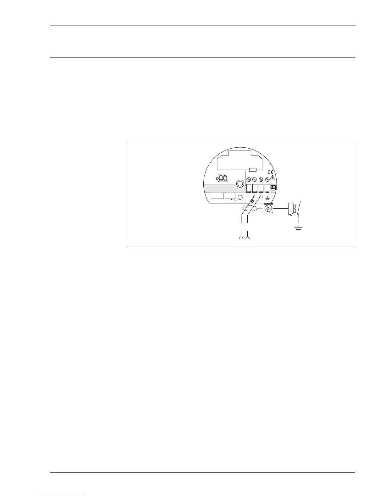
4 to 20 mA HART electronics – FEB22(P)
P01-DB5xxxxx-04-xx-xx-xx-005
0.2 to 1.2 mA analog electronics – FEB11(P)
The twin-core cable must be connected to terminals 2 (–) and 3 (+).
PFM electronics – FEB17(P)
The twin-core cable must be connected to terminals 2 (–) and 3 (+).
PRODFIBUS PA electronics – FEB24(P)
The twin-core cable must be connected to the "PA+" and "PA–" terminal.
More information on laying out and grounding the network is provided in Operating Instructions BA034S
"PROFIBUS DP/PA: Guidelines for planning and commissioning".
FOUNDATION Fieldbus electronics – FEB26
The twin-core cable must be connected to the "FF+" and "FF–" terminal.
More information on laying out and grounding the network is provided in Operating Instructions BA013S
"FOUNDATION Fieldbus Overview".
+
+
1
2
3
4
–
–
4…20 mA
DAT
FHB 20
FEB22P
FEB
22(P)
+
–
U
+
–
2
3
Page 16

Deltapilot S
16 Endress+Hauser
Supply voltage Note!
• When using the measuring device in hazardous areas, installation must comply with the corresponding
national standards and regulations and the Safety Instructions (XAs) or Installation or Control Drawings
(ZDs).
• All explosion protection data are given in separate documentation which is available upon request. The Ex
documentation is supplied as standard with all devices approved for use in explosion hazardous areas. → See
also Page 59 ff, "Safety Instructions" and "Installation/Control Drawings" sections.
0.2 to 1.2 mA analog
15 to 20 V DC
PFM
Version for non-hazardous areas: 14 to 16 V DC
4 to 20 mA HART
Version for non-hazardous areas: 11.5 to 30 V DC
PROFIBUS PA
• Version for non-hazardous areas and electronics without overvoltage protection: 9 to 32 V DC
• Version for non-hazardous areas and electronics with overvoltage protection: 9.6 to 32 V DC
FOUNDATION Fieldbus
Version for non-hazardous areas: 9 to 32 V DC
Current consumption PROFIBUS PA
10 mA ± 1 mA
FOUNDATION Fieldbus
11 mA ± 1 mA
Switch-on current 0.1 to 1.2 mA analog, PFM and 4 to 20 mA HART
100 mA for 30 V, pulse width half-life 20 ms
PROFIBUS PA and FOUNDATION Fieldbus
Switch-on current corresponds to Table 4, IEC 611158-2, Clause 2
Cable entry →See also Page 37 ff, feature 80 "Housing; Cable entry".
Cable specification 0.1 to 1.2 mA analog
• Endress+Hauser recommends using a shielded, three-core instrument cable with max. 25 Ω per core.
• Terminals for wire cross-section: 0.08 to 2.5 mm
2
PFM
• Endress+Hauser recommends using a shielded, twin-core instrument cable with max. 25 Ω per core.
• Terminals for wire cross-section: 0.08 to 2.5 mm
2
4 to 20 mA HART, PROFIBUS PA and FOUNDATION Fieldbus
• Endress+Hauser recommends using a twisted, shielded twin-core cable.
• Terminals for wire cross-section: 0.08 to 2.5 mm
2
Page 17
Deltapilot S
Endress+Hauser 17
Residual ripple 4 to 20 mA HART
• Max. ripple (measured at 500 Ω) 47 to 125 kHz: U
ss
≤ 200 mV
• Max. noise (measured at 500 Ω) 500 Hz to 10 kHz: U
eff
≤ = 2.2 mV
0.1 to 1.2 mA analog
In the range 1 Hz to 100 kHz: max. failsafe value U
SS
≤ 1 V
Performance characteristics
Reference operating
conditions
• As per DIN 16086
• Calibration temperature: +25°C (+77°F)
Position during calibration
Zero-point increase 90% of measuring range
Long-term stability ±0.1% of URL
1
per 6 months
Linearity Linearity as per the limit point method:
– ±0.2% of the set span
1
– Optional: ±0.1% of the set span
1
Hysteresis ±0.1% of URL
1
Influence of ambient
temperature
±0.01%/10 K of URL
1
Influence of medium
temperature
±0.1%/10 K of URL
1
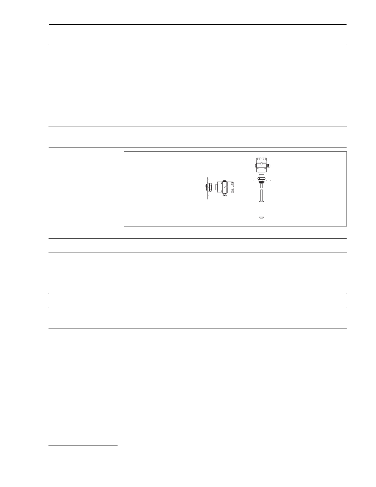
➀ DB50(A), DB50L,
DB50S
➁ DB51(A), DB 52(A),
DB53(A)
P01-DB5xxxxx-11-xx-xx-xx-009
ENDRESS+HAUSER
DELTAPILOT S
ENDRESS+HAUSER
DELTAPILOT S
➀
➁
1) For an explanation of terms, see Page 13
Page 18

Deltapilot S
18 Endress+Hauser
Operating conditions (installation)
Installation instructions for
compact version DB50,
DB50A, DB50L, DB50S
• Always install the device under the lowest measuring point.
• Do not install the device at the following positions:
In the filling curtain, in the tank outlet or at a point in the tank that can be reached by pressure pulses from
the agitator.
• The calibration and functional test can be carried out more easily if you mount the device after a shut-off
device.
• Deltapilot S must be included in the insulation for media that can harden when cold. The use of rod or cable
versions is also possible.
Installation instructions for
rod and cable versions
DB51(A), DB52(A) and
DB53(A)
• When mounting the rod and cable versions, make sure that the probe head is located at a point as free as
possible from flow. To protect the probe from impact from lateral movement, mount the probe in a guide
tube (preferably made of plastic) or secure it with a clamping fixture. For devices for Ex-areas, see Safety
Instructions (XAs).
• The length of the extension cable or the probe rod is based on the planned level zero point. The top of the
probe should be at least 5 cm under this.
Supplementary installation
instructions
Process diaphragm
• Do not use sharp or hard objects to handle or clean the process diaphragm. Build-up has no effect on the
measurement result as long it is porous and does not present a mechanical load on the diaphragm of the
pressure measuring cell.
• The process diaphragm on all Detapilot S rod and cable extension is protected against mechanical damage
by means of a plastic cover.
Seal
• Deltapilot S with G 1 1/2 thread:
When screwing the device into the tank, the flat seal supplied must be placed on the sealing surface of the
process connection.
• Deltapilot S with NPT thread:
– Wrap and seal the thread with Teflon tape.
– Tighten the device at the hexagon head only. Do not turn the device by the housing.
– Do not screw in the thread too tightly. Max. torque: 20...30 Nm
Sealing the probe housing
It is important that no moisture enters the housing while mounting the probe, connecting the electronic insert
and operating the measuring system.
• Always screw the housing cover and the cables entries tight.
• The O-Ring seal in the housing cover and the thread of the aluminum cover are lubricated. If this lubrication
has been removed, replace it with silicone grease or graphite paste, for example, so that the cover seals tight.
Do not use mineral-oil based greases. These can destroy the O-ring.
Page 19
Deltapilot S
Endress+Hauser 19
Housing adapter with
mounting bracket for humid,
damp and difficult-to-access
mounting locations
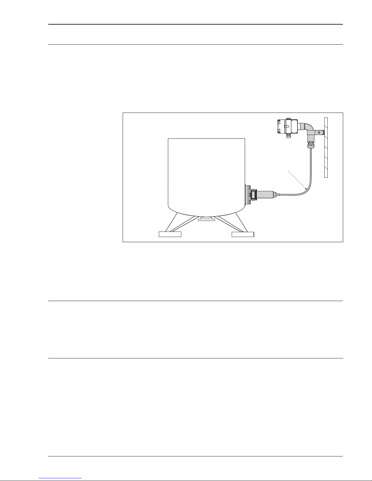
With the housing adapter and mounting bracket, you have the option of mounting the housing with the
electronic insert away from the measuring point. The allows problem-free measurement
• under particularly difficult measuring conditions (in confined or difficult-to-access mounting locations)
• in the event of extreme fluctuations in temperature at the tank wall.
You can operate and control the device quickly and comfortably away from the measuring point by means of
the FHB20 display and operating module or via remote operation. IP 68 ingress protection applies for the
housing adapter.
The mounting bracket is suitable for pipe and wall mounting.
P01-DB5xxxxx-11-xx-xx-xx-006
Measuring point with housing adapter and mounting bracket
1 Housing adapter
2 Mounting bracket for pipe and wall mounting
3Pipe bend
Note!
• When mounting, observe a bending radius of at least 200 mm.
Special measuring cells for
substances with hydrogen
formation
In the case of materials in which hydrogen formation occurs (e.g. digested sludge), hydrogen atoms can diffuse
through the metal diaphragm. This can result in incorrect measurement results.
For such instances, Endress+Hauser offers diaphragms with a gold-rhodium coating.
→ Order through 50 "Measuring cell version", type Z "Additional specification". In addition, for version "Z",
quote the order number 52009331.
Note!
• To reduce the formation of hydrogen, you should refrain from using galvanized assemblies.
Special measuring cell for
acids, alkalis or sea water
For acids, alkalis or sea water, Endress+Hauser offers diaphragms with a gold-platinum coating.
→ Order through 50 "Measuring cell version", type Z "Additional specification". In addition, indicate the order
number 52009332 for Version 'Z'.
IP 68
R 200
m
m
³
➀
➁
➂
Page 20

Deltapilot S
20 Endress+Hauser
Operating conditions (environment)
Ambient temperature range • –20 to +60°C (–4 to +140°F)
• With separate electronics: –20 to +85°C (–4 to +185°F)
For devices for use in hazardous areas, see Safety Instructions (XAs), Installation or Control Drawing (ZDs).
Ambient temperature limits –40 to +85°C (–40 to +185°F)
The device can be operated in this temperature range. When commissioning the device, the temperature
cannot go below –20°C (–4°F). The values of the specification such as accuracy can be overshot here.
Storage temperature range –40 to +85°C (–40 to +185°F)
Vibration resistance 10 to 55 Hz, 2 g, as per DIN EN 60068-2-6
Degree of protection • → See Page 37 ff, feature 80 "Housing; Cable entry".
• Housing: IP 66/NEMA 4X
• Housing adapter: IP 68 (1 mH
2
O for 24 h)
Electromagnetic compatibility
(EMC)
Interference emission as per EN 61326, electrical device B; interference immunity as per EN 61326 appendix
A (industrial use) and NAMUR EMC recommendation (NE21).
Overvoltage protection The following electronic inserts are equipped with an surge arrester:
– 0.2 to 1.2 mA analog – FEB11P
– PFM – FEB17P
– 4 to 20 mA HART – FEB22P
– PROFIBUS PA – FEB24P
Protective diodes: gas tube surge arrester 230 V, nominal discharge current 10 kA
Page 21
Deltapilot S
Endress+Hauser 21
Operating conditions (process)
Process temperature range
For devices for use in hazardous areas, see Safety Instructions (XAs), Installation or Control Drawing (ZDs).
Process temperature limits • DB51(A), DB52(A) and DB53(A): –40 to +85°C (–40 to +185°F)
• The DB50L and DB50S versions can be exposed to +135°C (+275°F) for a brief period (maximum
30 minutes) for cleaning purposes.
Process pressure limits → For overload and vacuum resistance see Page 12, "Measuring range" section.
Mechanical construction
Dimensions of housing
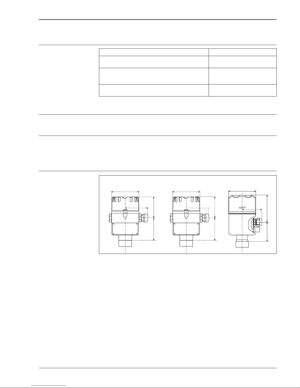
P01-DB5xxxxx-06-xx-xx-xx-008
Deltapilot S housing versions
1 Aluminum housing
2 Polyester housing
3 Stainless steel housing
Dimensions written in italics apply to devices with a cover including a sight glass. Devices with the FHB20 onsite display
are always supplied with a cover with a sight glass.
Device Process temperature range
– DB50(A)
– DB50L, DB50S
–10 to +100°C (+14 to +212°F)
– DB51(A)
– DB52(A) with FEP extension cable
– DB53(A) with FEP extension cable
–10 to +80°C (+14 to +176°F)
– DB52(A) with PE extension cable
– DB53(A) with PE extension cable
–10 to +70°C (+14 to +158°F)
63
~66
68
ø86
~
75
68
ø86
~
75
ø86
➀
➁
➂
68
89
76
76
72
88
Page 22
Deltapilot S
22 Endress+Hauser
Process connections DB50 and
DB50A (compact version)
Threaded connection ISO 228 and NPT
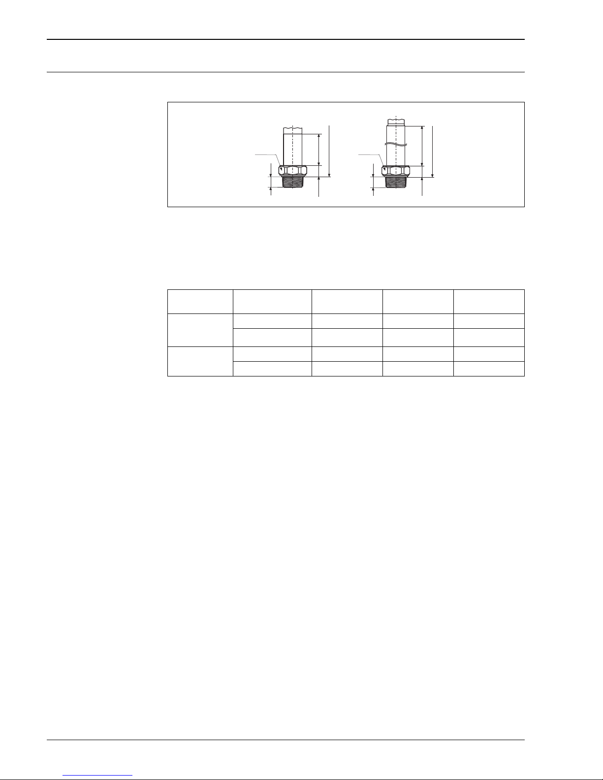
P01-DB5xxxxx-06-xx-xx-xx-023
DB50(A) with thread
1 DB50(A) with thread G 1 1/2 or 1 1/2 NPT without flame barrier
2 DB50(A) with thread G 1 1/2 or 1 1/1 NPT with flame barrier
(flame barrier for use in hazardous areas, Zone 0)
Installation height H, devices with a thread
➁
146
22.5
25
H
➀
46.7
22.5
25H25
SW 60 SW 60
Cover Aluminum housing
[mm]
Polyester housing
[mm]
Stainless steel
housing [mm]
Without a flame
barrier
Flat 205.2 213.2 204.2
High (with sight glass)
1
1) Devices with the FHB20 display and operating module are always supplied with a high cover or with a cover with a
sight glass.
226.2 213.2 220.2
With a flame barrier Flat 304.5 312.5 204.2
High (with sight glass)
1
325.5 312.5 231.5
Page 23
Deltapilot S
Endress+Hauser 23
EN/DIN, ANSI and JIS flanges
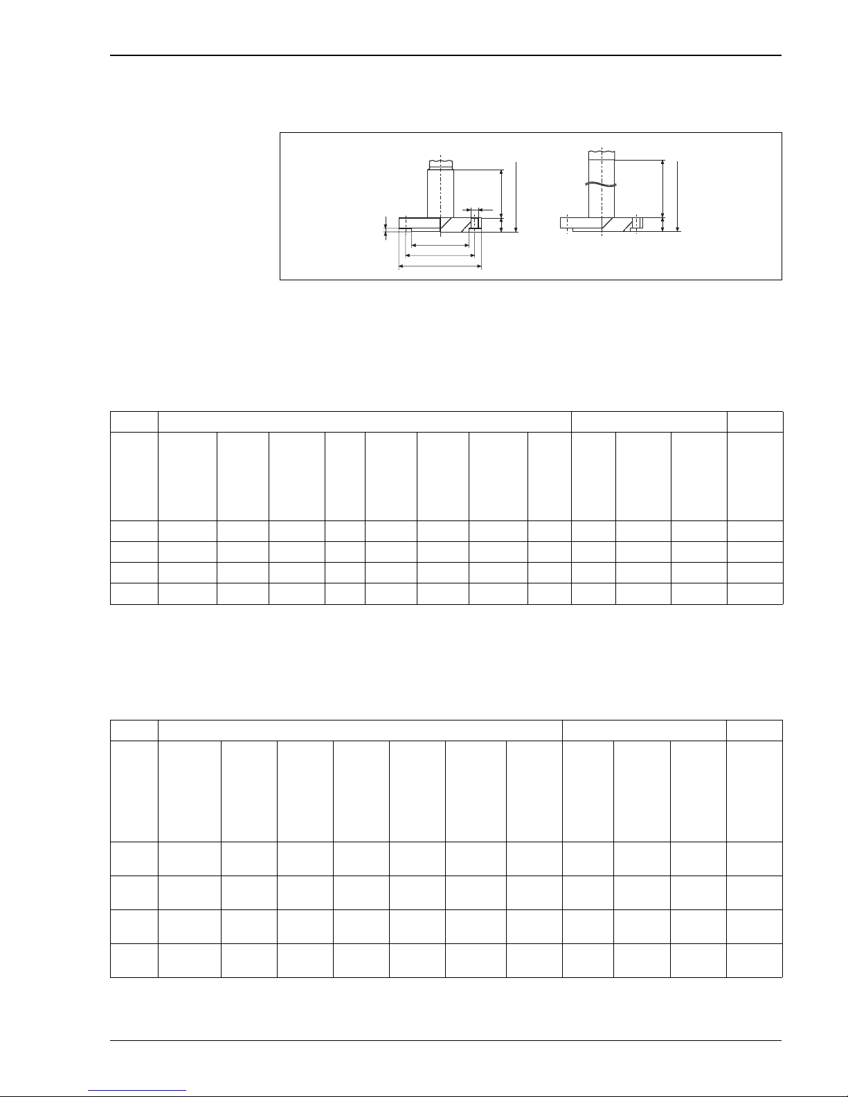
P01-DB5xxxxx-06-xx-xx-xx-024
DB50(A) with flange; surface roughness of the surfaces in contact with the medium EN/DIN: Ra = 10 to 12.5 μm,
ANSI: R
a
= 3.2 to 6.3 μm, JIS: Ra = 3.2 to 6.3 μm
1 DB50(A), flange without flame barrier
2 DB50(A), flange with flame barrier (flame barrier for use in hazardous areas, Zone 0)
H For installation height H, see Page 24
EN/DIN flanges, connection dimensions as per EN 1092-1 (old DIN 2526 Form C)
ANSI flanges, connection dimensions as per ANSI B 16.5, raised face RF
➀
185
b
H
k
D
f
g
2
55.7
b
H
➁
g
Flange Screwholes
Version Material
1
Nominal
diameter
Nominal
pressure
Shape2Diameter Thick-
ness
Raised face
diameter
Raised
face
height
Quantity
Diameter Hole
circle
Flange
weight
3
Db g f g2k
[mm] [mm] [mm] [mm] [mm] [mm] [kg]
20 AISI 316L DN 40 PN 10/16 B1 (C) 150 16 88 3 4 18 110 2.3
21 AISI 316L DN 50 PN 10/16 B1 (C) 165 18 102 3 4 18 125 3.0
22 AISI 316L DN 80 PN 10/16 B1 (C) 200 24 138 3 8 18 160 4.8
23 AISI 316L DN 100 PN 10/16 B1 (C) 220 20 158 3 8 18 180 6.0
1) AISI 316L/1.4435
2) Designation as per DIN 2526 in brackets
3) Housing weight, see Page 32
Flange Screwholes
Version Material
1
Nominal
diameter
Class Diameter Thickness Raised face
diameter
Raised
face
height
Quantity Diameter Hole
circle
Flange
weight
2
Db g f g2k
[in] [lb./sq in] [in]
[mm]
[in]
[mm]
[in]
[mm]
[in]
[mm]
[in]
[mm]
[in]
[mm]
[kg]
30 AISI 316/
316L
1 1/2 150 5
127
0.69
17.5
2.88
73.2
0.06
1.6
40.62
15.7
3.88
98.6
1.8
31 AISI 316/
316L
21506
152.4
0.75
19.1
3.62
91.9
0.06
1.6
40.75
19.1
4.75
120.7
2.7
32 AISI 316/
316L
31507.5
190.5
0.94
23.9
5
127
0.06
1.6
40.75
19.1
6
152.4
5.4
33 AISI 316/
316L
4 150 9
228.6
0.94
23.9
6.19
157.2
0.06
1.6
80.75
19.1
7.5
190.5
7.5
1) Combination of AISI 316 for required pressure resistance and AISI 316L for required chemical resistance (dual rated)
2) Weight incl. pipe, housing weight, see Page 32
Page 24

Deltapilot S
24 Endress+Hauser
JIS flanges, connection dimensions as per JIS B 2220, raised face RF
Installation height H, devices with a flange
Flange Screwholes
Version Material
1
Nominal
diameter
Nominal
pressure
Diameter Thickness Raised face
diameter
Raised
face
height
Quantity Diameter Hole
circle
Flange
weight
2
Db g f g2k
[mm] [mm] [mm] [mm] [mm] [mm] [kg]
7B AISI 316L 40 A 10 K 144 16 81 2 4 19 105 1.8
7C AISI 316L 50 A 10 K 155 16 96 2 4 19 120 2.2
7D AISI 316L 80 A 10 K 185 18 127 2 8 19 150 3.5
7L AISI 316L 100 A 10 K 210 18 151 2 8 19 175 4.6
1) AISI 316L/1.4435
2) Weight incl. pipe, housing weight, see Page 32
Cover Aluminum housing
[mm]
Polyester housing
[mm]
Stainless steel
housing [mm]
Without a flame
barrier
Flat 201 + flange
thickness b
201 + flange
thickness b
189 + flange
thickness b
High (with sight glass)
1
1) Devices with the FHB20 display and operating module are always supplied with a high cover or with a cover with a
sight glass.
212 + flange
thickness b
201 + flange
thickness b
205 + flange
thickness b
With a flame barrier Flat 312 + flange
thickness b
322 + flange
thickness b
310 + flange
thickness b
High (with sight glass) 333 + flange
thickness b
322 + flange
thickness b
326 + flange
thickness b
Page 25
Deltapilot S
Endress+Hauser 25
Process connection DB50L
and DB50S (food version)
Universal process adapter
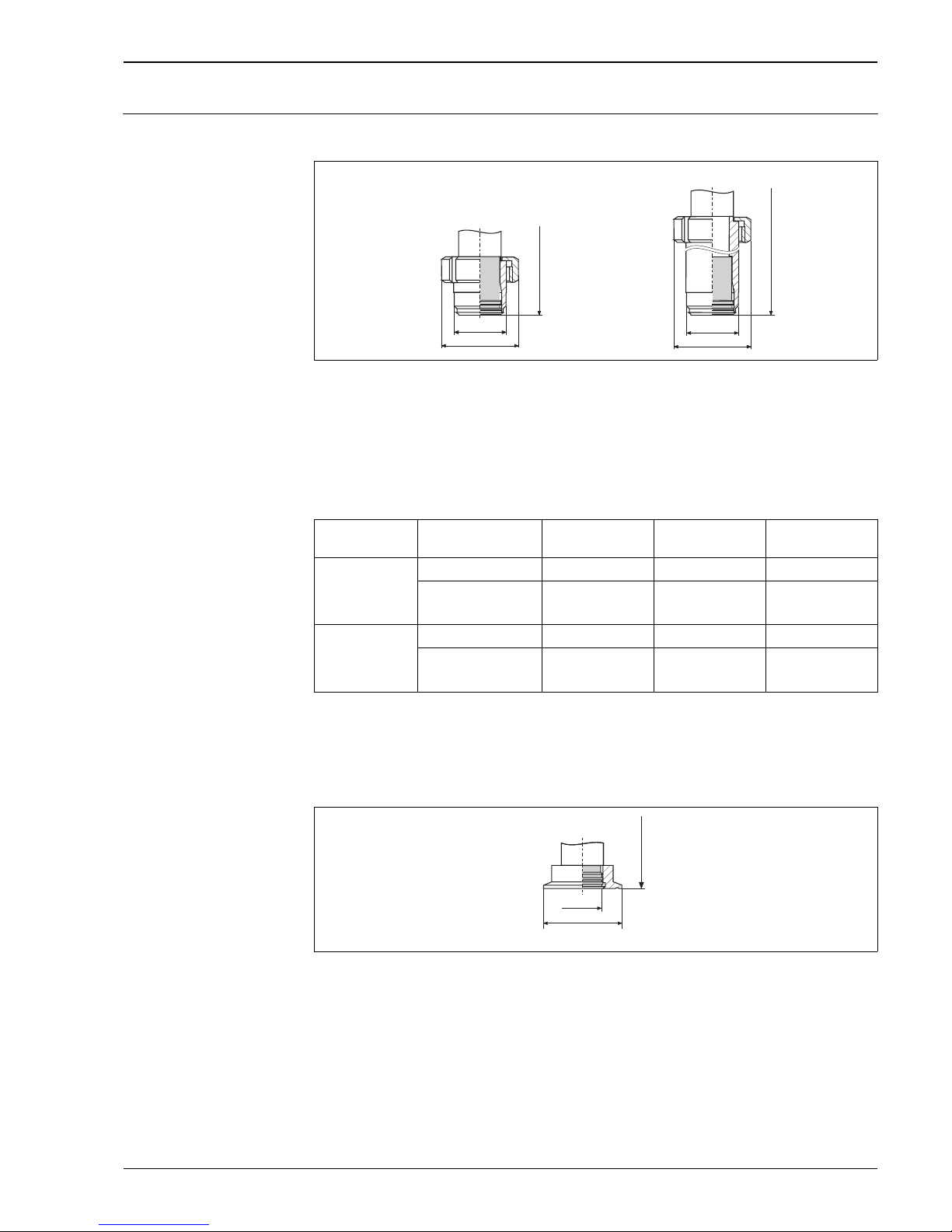
P01-DB5xxxxx-06-xx-xx-xx-021
Process connection DB50L/DB50S, material: AISI 316L/1.4435;
Surface roughness of the surfaces in contact with the medium R
a
≤ 0.8 μm as standard. Lower surface roughness on
request.
1 Version 00: universal process adapter incl. silicone molded seal, 3A
2 Version 57: universal process adapter, extension 6 inch incl. silicone molded seal, 3A
Installation height H, devices with universal process adapter
Tri-Clamp ISO 2852
P01-DB5xxxxx-06-xx-xx-xx-015
Process connection DB50L/DB50S, version 50: Tri-Clamp ISO 2852 DN 40 – DN 51 (2")/DIN 32676 DN 50, EHEDG, 3A;
Material: AISI 316L/1.4435; surface roughness of surfaces in contact with the medium R
a
≤ 0.8 μm as standard. Lower
surface roughness on request.
ø43.5
ø63
➀
ø43.5
ø63
➁
H
H
Cover Aluminum housing
[mm]
Polyester housing
[mm]
Stainless steel
housing [mm]
Universal process
adapter
Flat 221 221 209
High (with sight glass)
1
1) Devices with the FHB20 display and operating module are always supplied with a high cover or with a cover with a
sight glass.
232 221 225
Universal process
adapter with 6 inch
extension
Flat 318 318 306
High (with sight glass) 329 318 322
H
ø35.8
ø64
Page 26
Deltapilot S
26 Endress+Hauser
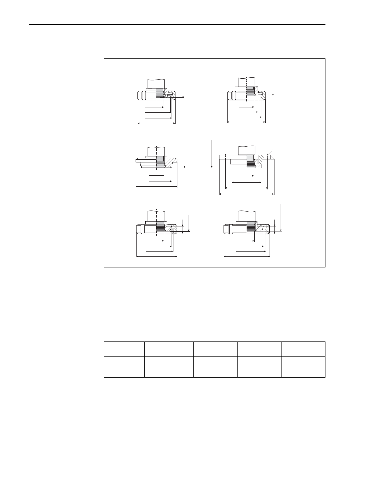
Hygienic connections
P01-DB5xxxxx-06-xx-xx-xx-016
Hygienic connections DB50L: DIN 11851 with coupling nut, material: AISI 316L/1.4435, surface roughness of surfaces
in contact with the medium R
a
≤ 0.8 μm as standard. Lower surface roughness on request.
1 Version 53: SMS 2" PN 25, EHEDG, 3A
2 Version 56: ISO 2385 IDF 2", EHEDG, 3A
3 Version 55 : Varivent type N for pipes DN 40 – DN 162 PN 40, EHEDG
4 Version 44: DRD 65 mm PN 25, EHEDG, 3A
5 Version 40: DIN 11851 DN 40 PN 40
6 Version 41: DIN 11851 DN 50 PN 40
Installation height H, devices with universal process adapter, Tri-Clamp or hygienic connection
H
78
ø35.8
10
ø56
Rd 65x1/6
H
92
11
ø68
Rd 78x1/6
ø35.8
4xø11.5
ø65
ø84
H
ø35.8
ø84
ø105
ø35.8
ø68
ø84
H
H
ø35.8
ø77
ø65.3
ø54.2
ø65
ø35.8
H
ø84
Rd 70x1.6"
➀
➂
➁
➃
➄
➅
Cover Aluminum housing
[mm]
Polyester housing
[mm]
Stainless steel
housing [mm]
Without a flame
barrier
Flat 221 221 209
High (with sight glass)
1
1) Devices with the FHB20 display and operating module are always supplied with a high cover or with a cover with a
sight glass.
232 221 225
Page 27
Deltapilot S
Endress+Hauser 27
Process connections DB51 and
DB51A (rod/pipe version)
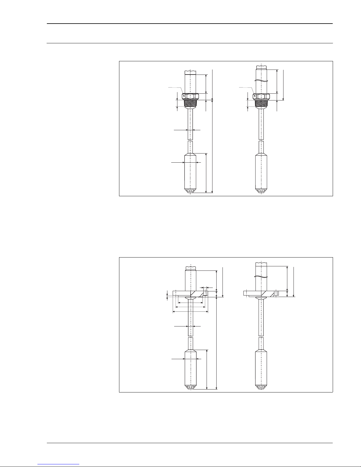
Threaded connection ISO 228 and NPT
P01-DB5xxxxx-06-xx-xx-xx-026
DB51(A), rod version with thread
1 DB51(A), thread G 1 1/2 or 1 1/2 NPT without flame barrier
2 DB51 (A), thread G 1 1/2 or 1 1/2 NPT with flame barrier
(flame barrier for use in hazardous areas, Zone 0)
H For installation height H, see Page 22
EN/DIN, ANSI and JIS flanges
P01-DB5xxxxx-06-xx-xx-xx-027
DB51(A), rod version with flange
1 DB51(A), flange without flame barrier
2 DB51(A), flange with flame barrier
(flame barrier for use in hazardous areas, Zone 0)
H For installation height H, see Page 24
→ For process connection dimensions, see Page 23 ff.
➁
146
22.5
25
H
SW 60
ø42.5
➀
46.7
22.5
25
H
ø17.2
230
DB 51: L = 400…4000 mm
DB 51 A: L = 16…160 inch
SW 60
➁
185
b
H
➀
k
D
f
g
2
55.7
b
H
g
ø42.5
ø17.2
230
DB 51: L = 400…4000 mm
DB 51 A: L = 16…160 inch
Page 28
Deltapilot S
28 Endress+Hauser
Dimensions of Deltapilot S
DB52 and DB52A (cable
version)
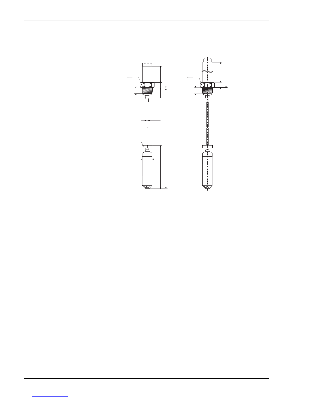
Threaded connection ISO 228 and NPT
P01-DB5xxxxx-06-xx-xx-xx-028
DB52(A), cable version with thread
1 DB52(A), thread G 1 1/2 and 1 1/2 NPT without flame barrier
2 DB52(A), thread G 1 1/2 and 1 1/2 NPT with flame barrier
(flame barrier for use in hazardous areas, Zone 0)
3 Clamp for clamping fixture
H For installation height H, see Page 22
LProbe length:
Without approval, EEx nA II T6: 0.5 to 200 m (20 to 7874 inch)
EEx ia IIC T6, FM IS, CSA IS: 0.5 to 100 m (20 to 3937 inch)
➀
46.7
22.5
25
ø10.4
ø42.5
257
L
H
➂
SW 60
➁
146
22.5
25
H
SW 60
Page 29
Deltapilot S
Endress+Hauser 29
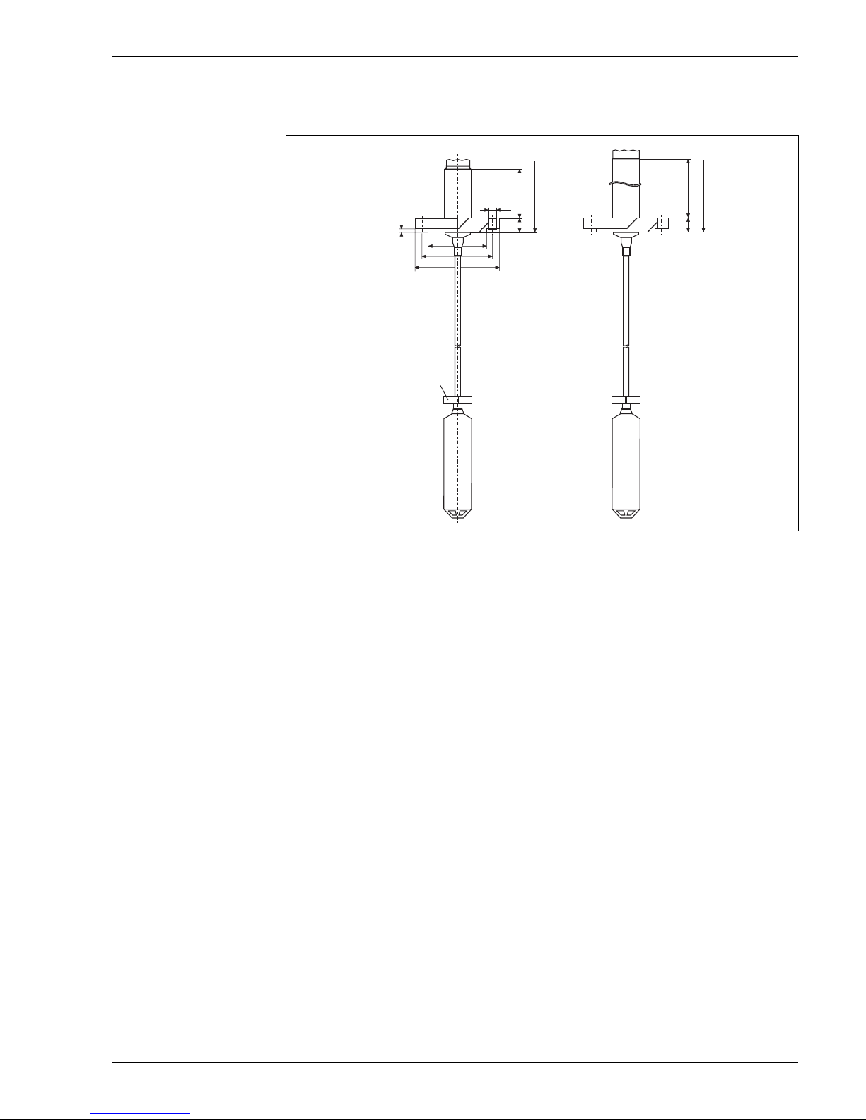
EN/DIN, ANSI and JIS flanges
P01-DB5xxxxx-06-xx-xx-xx-029
DB52(A), cable version with flange
1 DB52(A), flange without flame barrier
2 DB52(A), flange with flame barrier
(flame barrier for use in hazardous areas, Zone 0)
3 Clamp for clamping fixture
H For installation height H, see Page 24
LProbe length:
Without approval, EEx nA II T6: 0.5 to 200 m (20 to 7874 inch)
EEx ia IIC T6, FM IS, CSA IS: 0.5 to 100 m (20 to 3937 inch)
→ For process connection dimensions, see Page 23 ff.
➁➀
k
D
f
g
2
55.7
b
H
185
b
HH
➂
g
Page 30
Deltapilot S
30 Endress+Hauser
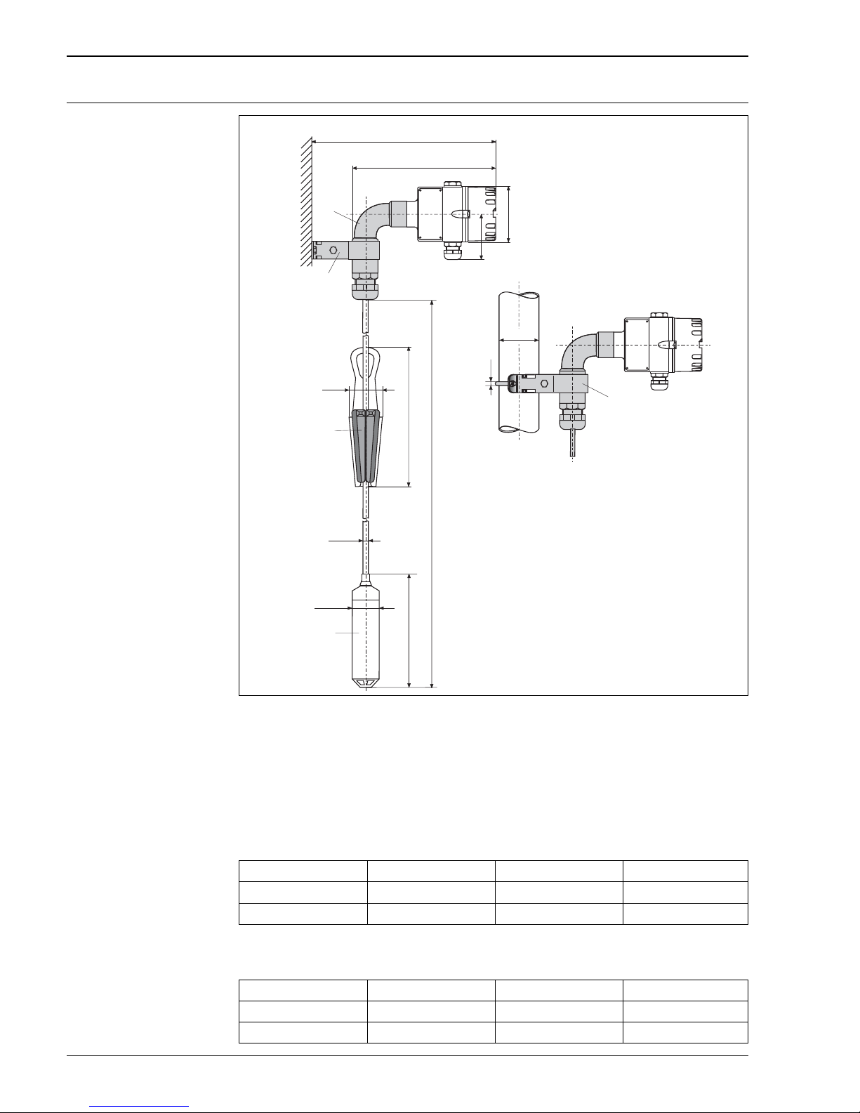
Dimensions of Deltapilot S
DB53 and DB53A (suspension
clamp and mounting bracket)
P01-DB5xxxxx-06-xx-xx-xx-007
DB53 with suspension clamp and mounting bracket
1Pipe bend
2 Mounting bracket for pipe and wall mounting
3 Suspension clamp
4Measuring cell tube
LProbe length:
Without approval, EEx nA II T6: 0.5 to 200 m (20 to 7874 inch)
EEx ia IIC T6, FM IS, CSA IS: 0.5 to 100 m (20 to 3937 inch)
Dimension A
Dimension H
~66
~280
H max. 241
A max. 286
ø86
~
75
ø42.5
2"
ø6
L
ø10.4
240
➁
➀
➂
➃
➁
Cover Aluminum housing Polyester housing Stainless steel housing
Flat 265 mm 273 mm 264 mm
High (with sight glass) 286 mm 273 mm 280 mm
Cover Aluminum housing Polyester housing Stainless steel housing
Flat 219 mm 227 mm 218 mm
High (with sight glass) 240 mm 227 mm 234 mm
Page 31
Deltapilot S
Endress+Hauser 31
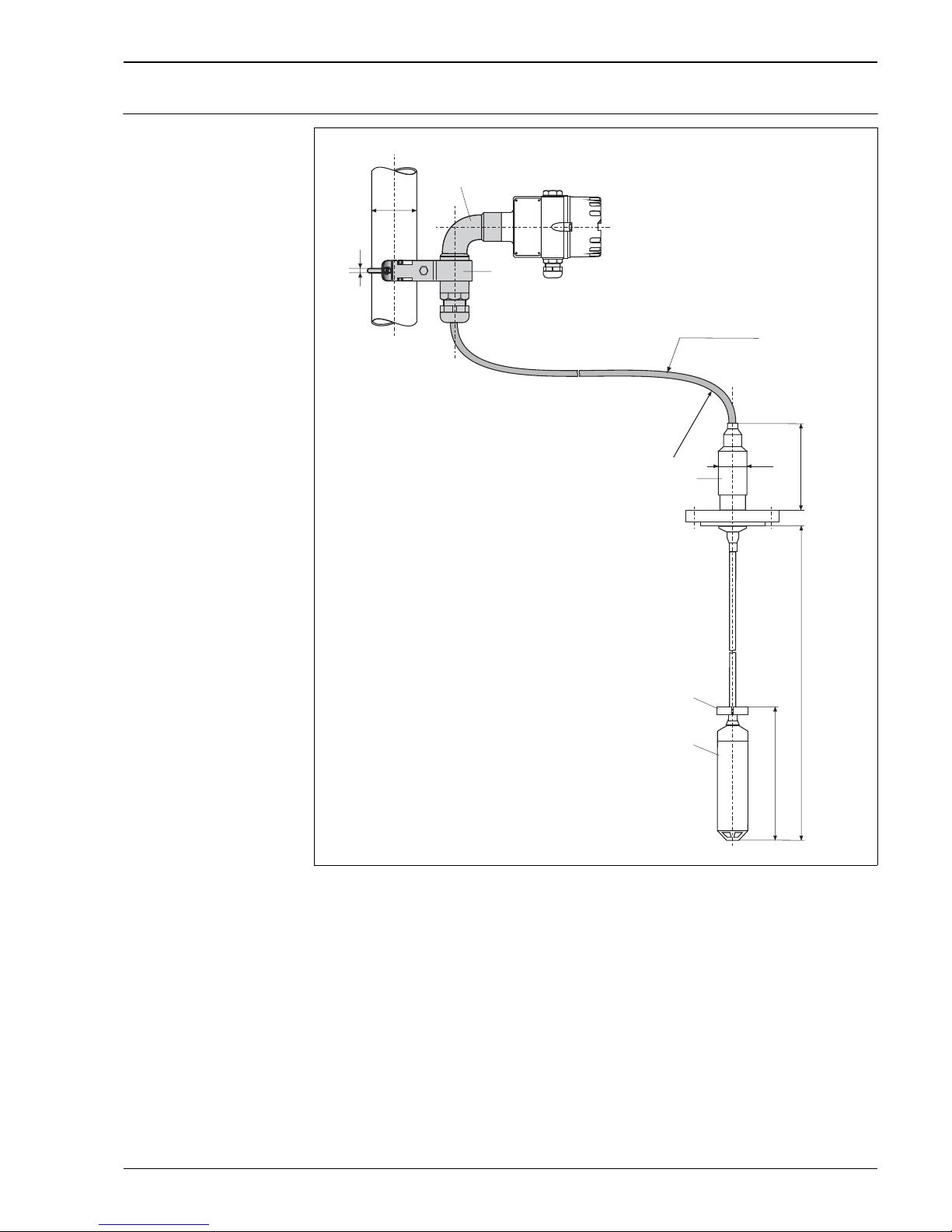
Dimensions of connecting
cable with housing adapter
and mounting bracket
P01-DB5xxxxx-06-xx-xx-xx-013
Connecting cable with housing adapter and mounting bracket, here shown with a DB52
1Pipe bend
2 Mounting bracket for pipe and wall mounting
3 Housing adapter
4 Clamp for clamping fixture
5 Measuring cell tube
LProbe length
Note!
• For DB50, DB50L, DB51, DB52, order the housing adapter and the mounting bracket via feature 90
"Additional option" or subsequently as an accessory. → See also Page 19 and Page 56, "Housing adapter with
mounting bracket" section.
• When using a housing adapter in the EEx ia, FM IS or CSA IS area, the total cable length (connecting cable
(L1) + extension cable (L2)) must not exceed 100 m.
2"
ø6
218
L1 max. 20 m
ø40
257
L2
EEx ia, FM IS, CSA IS:
L1 + L2 100 m (3937 inch)≤
R 200 mm≥
➁
➀
➂
➃
➄
Page 32
Deltapilot S
32 Endress+Hauser
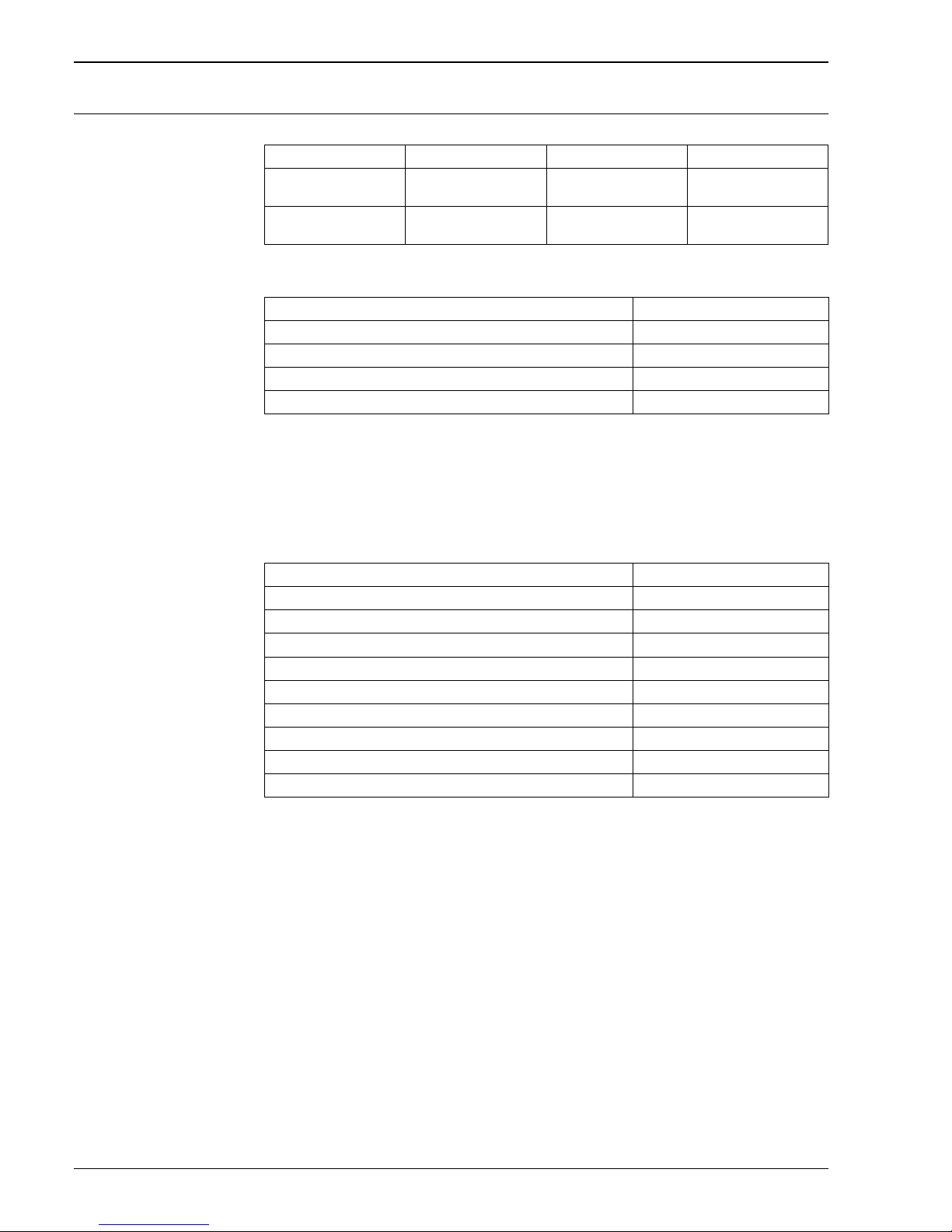
Weight Housing
Process connection DB50(A)
Note!
• Total weight of device with threaded connection = weight of housing + weight of process connection
DB50(A)
• Total weight of device with flange connection = weight of housing + weight of process connection DB50(A)
+ weight of flange (→ see Page 23 ff)
Deltapilot process connections DB50L and DB50S (food version)
Note!
• Total weight of device = weight of housing + weight of process connection DB50L and DB50S
Aluminum housing Polyester housing Stainless steel housing
With flat cover, incl.
electronic insert
0.8 kg 0.7 kg 0.9 kg
With high cover, incl.
electronic insert
1.15 kg 0.7 kg 1.0 kg
Process connection incl. sensor Weight
Threaded connection without a flame barrier incl. sensor 0.8 kg
Threaded connection with a flame barrier incl. sensor 1.35 kg
Flange connection without a flame barrier incl. sensor, without a flange 0.45 kg
Flange connection with a flame barrier incl. sensor, without a flange 1.0 kg
Process connection incl. sensor Weight
Tri-Clamp ISO 2852 DN 40 – DN 51 (2")/DIN 32676 DN 50 0.6 kg
SMS 2" incl. nut 0.95 kg
ISO 2385 IDF 2" incl. nut 1.0 kg
Varivent type N for pipes DN 40 – DN 162 0.9 kg
DRD 65 mm 1.05 kg
DIN 11851 dairy fitting DN 40 incl. nut 0.8 kg
DIN 11851 dairy fitting DN 50 incl. nut 1.1 kg
Universal process adapter 0.7 kg
Universal process adapter with 6 inch extended diaphragm seal 1.5 kg
Page 33

Deltapilot S
Endress+Hauser 33
Process connection and pipe DB51(A)
Note!
• Total weight of device with threaded connection = weight of housing + weight of pipe incl. cable x length
+ weight of process connection DB51(A)
• Total weight of device with flange connection = weight of housing + weight of pipe incl. cable x length +
weight of process connection DB51(A)+ weight of flange (→ see Page 23 ff)
Process connection and cable DB52(A)
Note!
• Total weight of device with threaded connection = weight of housing + weight of cable x length + weight
of process connection DB52(A)
• Total weight of device with flange connection = weight of housing + weight of cable x length + weight of
process connection DB52(A)+ weight of flange (→ see Page 23 ff)
Process connection DB53 (A) – securing with suspension clamp and mounting bracket
Note!
• Total weight of device = weight of housing + weight of cable x length + weight of mounting bracket +
weight of pipe bend + weight of suspension clamp + weight of measuring cell tube
Process connection incl. sensor Weight
Pipe incl. cable 0.77 kg/m
Threaded connection without a flame barrier incl. measuring cell tube and
sensor
1.65 kg
Threaded connection with a flame barrier incl. measuring cell tube and sensor 2.2 kg
Flange connection without a flame barrier incl. measuring cell tube and sensor,
without a flange
1.3 kg
Flange connection with a flame barrier incl. measuring cell tube and sensor,
without a flange
1.85 kg
Process connection incl. sensor Weight
PE cable 0.13 kg/m
FEP cable 0.18 kg/m
Threaded connection without a flame barrier incl. measuring cell tube and
sensor
1.65 kg
Threaded connection with a flame barrier incl. measuring cell tube and sensor 2.2 kg
Flange connection without a flame barrier incl. measuring cell tube and sensor,
without a flange
1.3 kg
Flange connection with a flame barrier incl. measuring cell tube and sensor,
without a flange
1.85 kg
Process connection incl. sensor Weight
PE cable 0.13 kg/m
FEP cable 0.18 kg/m
Mounting bracket 0.2 kg
Pipe bend incl. cable entry 0.65 kg
Suspension clamp 0.4 kg
Measuring cell tube incl. sensor 1.0 kg
Page 34

Deltapilot S
34 Endress+Hauser
Weight of additional options
Material Housing
• Electronic insert: plastic ABS housing, cast electronic insert
• Process connections: AISI 316L (1.4435) or Alloy C4 (2.4610)
• Process diaphragm: Alloy C276 (2.4819)
• Measuring cell: AISI 316L (1.4435) or C276 (2.4819)
• Probe tube DB51(A): AISI 316L (1.4435) or Alloy C4 (2.4610)
• Extension cable DB52(A) and DB53(A): multi-core cable with steel wire braiding, FEP or PE insulation
• Measuring cell tube DB51(A), DB52(A) and DB53(A): AISI 316L (1.4435) or
Alloy C4 (2.4610)/C22 (2.4602)
• Suspension clamp: AISI 316L (1.4404) and fiberglass reinforced polyamide (PA)
•Seals
– For measuring cell sealing, see Ordering information, Page 36
– Universal process adapter: silicone profile packing, suitable for foodstuffs in accordance with BGA XV
FDA 21 CRF 177.2600
– Process connection DRD: PTFE seal
• Protection cap for diaphragm DB51, DB52, DB53: PFA (perflouralkoxy) plastic
• Clamp for clamping fixture for DB52(A): PFA (perflouralkoxy) plastic, AISI 304 (1.4301)
• Housing adapter and pipe bend:
– Housing adapter: AISI 316L (1.4435) and AISI 316 Ti (1.4571)
– Multi-core cable with steel braiding, PE insulation
–Pipe bend:
– AISI 316 Ti (1.4571) and AISI 321 (1.4541)
–Cable gland:
– CuZn nickel-plated
–O-ring: NBR
– Sealing insert: TPE-V
–O-ring: EPDM
• Mounting bracket: AISI 304 (1.4301)
Accessories Weight
Mounting bracket 0.2 kg
Pipe bend incl. cable entry 0.65 kg
Housing adapter for DB51(A) and DB 52(A) 0.85 kg
Housing adapter for DB50(A) and DB50L/S 0.7 kg
Aluminum housing Polyester housing Stainless steel housing
Housing EN AC-44300
(GD-AISi12) with synthetic
coating, blue/gray
Fiberglass reinforced
polyester, blue/gray
(PBT-GF)
AISI 316L (1.4404)
Flat cover EN AC-44300 with
synthetic coating, gray
Fiberglass reinforced
polyester, gray (PBT-GF)
AISI 316L (1.4404)
High cover with sight glass EN AC-44300 with
synthetic coating, gray
Polycarbonate (PC) AISI 316L (1.4404)
Sight glass Glass Polycarbonate (PC) Glass
Seal for housing cover EPDM O-ring Silicone O-ring (VQM) Silicone molded seal (VQM)
Page 35

Deltapilot S
Endress+Hauser 35
Certificates and approvals
CE mark The device meets the legal requirements of the EC directives. Endress+Hauser confirms that the device has
been successfully tested by applying the CE mark.
Ex approvals All explosion protection data are given in separate documentation which is available upon request. The Ex
documentation is supplied as standard with all devices approved for use in explosion hazardous areas.
→ See also Page 59 ff, "Safety Instructions" and "Installation/Control Drawings" sections.
Overfill protection WHG (German Water Resources Act)
Seismic test DB53 with FEB22 electronic insert passed in accordance with IEEE 344-1987.
Marine approval DB50, DB50L, DB52 and DB53 with FEB17 electronic insert:
German Lloyd, certificate No.: 99350 - 97 HH
Standards and guidelines DIN EN 60770 (IEC 60770):
Transmitters for controlling in systems used in industrial process technology
Part 1: Methods for evaluating the operating behavior
DIN 16086:
Electrical pressure measuring devices, pressure sensors, transmitters, pressure measuring devices
Terms, specifications in data sheets
EN 61326:
Electrical equipment for control technology and laboratory application – EMC requirements
Page 36
Deltapilot S
36 Endress+Hauser
Ordering information
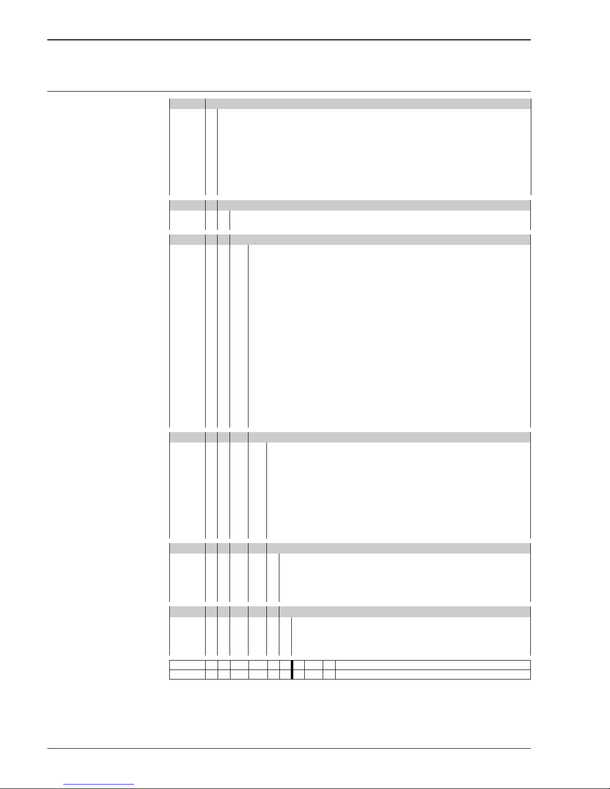
DB50 – compact version
→For continuation of ordering information for DB50, see the following page.
10 Approval:
A Version for non-hazardous area
E Version for non-hazardous area, overfill protection WHG
G ATEX II 1/2 G EEx ia IIC T6
C ATEX II 1/2 G EEx ia IIC T6, flame barrier
D ATEX II 1/2 G EEx ia IIC T6, overfill protection WHG
B ATEX II 1/2 G EEx ia IIC T6, flame barrier, overfill protection WHG
N ATEX II 3 G EEx nA II T6
S CSA IS, Class I, Division 1, Groups A – D
T CSA IS, Class I, Division 2, Groups A – D
20 Probe:
B Compact version + inspection certificate as per EN 10204–3.1 material (AISI 316L wetted)
C Compact version
30 Process connection:
Threaded connections
10 ISO 228 G 1 1/2, AISI 316L
11 ISO 228 G 1 1/2, Alloy C
12 ANSI 1 1/2 NPT, AISI 316L
EN flanges
20 DN 40 PN 10/16 B1, AISI 316L
21 DN 50 PN 10/16 B1, AISI 316L
22 DN 80 PN 10/16 B1, AISI 316L
23 DN 100 PN 10/16 B1, AISI 316L
ANSI flanges
30 1 1/2" 150 Ibs RF, AISI 316/316L
31 2" 150 lbs RF, AISI 316/316L
32 3" 150 Ibs RF, AISI 316/316L
33 4" 150 lbs RF, AISI 316/316L
JIS flanges
7B 10K 40A RF, AISI 316L
7C 10K 50A RF, AISI 316L
7D 10K 80A RF, AISI 316L
7L 10K 100A RF, AISI 316L
40 Measuring range:
BA 0 to 100 mbar/1 mH2O/40 inH2O
BB 0 to 400 mbar/4 mH
2
O/160 inH2O
BC 0 to 1200 mbar/12 mH
2
O/480 inH2O
BD 0 to 4000 mbar/40 mH
2
O/1600 inH2O
BE 0 to 10 bar/100 mH
2
O/4000 inH2O
DA –100 to 100 mbar/1 mH
2
O/40 inH2O
DB –400 to 400 mbar/4 mH
2
O/160 inH2O
DC –900 to 1200 mbar/12 mH
2
O/480 inH2O
DD –900 to 4000 mbar/40 mH
2
O/1600 inH2O
DE –0.9 to 10 bar/100 mH
2
O/4000 inH2O
50 Linearity; Fill fluid:
1 < 0.2 % of measuring range; FDA compliant
2 < 0.2 % of measuring range; inert oil
3 < 0.1 % of measuring range; FDA compliant
4 < 0.1 % of measuring range; inert oil
Z Additional specification
60 Measuring sensor seal:
1Viton
2EPDM
5Kalrez
3 Sensor welded
DB50 Order code
Page 37
Deltapilot S
Endress+Hauser 37
DB50 – compact version
(continued)
70 Electronics; Output:
Electronic inserts without integrated overvoltage protection
A Without integrated electronic insert (e.g. for ordering spare parts)
B FEB11, 3-wire analog signal
C FEB17, 2-wire PFM signal
E FEB22, 4 to 2 0 mA HART
G FEB22, 4 to 20 mA HART, with FHB20 onsite display
H FEB24, PROFIBUS PA
K FEB24, PROFIBUS PA, with FHB20 onsite display
1 FEB26, FOUNDATION Fieldbus
2 FEB26, FOUNDATION Fieldbus, with FHB20 onsite display
Electronic inserts with integrated overvoltage protection
M FEB11P, 3-wire analog signal
N FEB17P, 2-wire PFM signal
R FEB22P, 4 to 20 mA HART
T FEB22P, 4 to 20 mA HART, with FHB20 onsite display
U FEB24P , PROFIBUS PA
W FEB24P, PROFIBUS PA, with FHB20 onsite display
80 Housing; Cable entry:
A0 Without housing (e.g. for ordering spare parts)
G1 Polyester housing, IP 66, gland M 20x1.5
G2 Aluminum housing, IP 66, gland M 20x1.5
G3 AISI 316L housing, IP 66, gland M 20x1.5
P2 Aluminum housing, IP 66, plug M 12x1
P3 AISI 316L housing, IP 66, plug M 12x1
T2 Aluminum housing, IP 66, plug 7/8"
T3 AISI 316L housing, IP 66, plug 7/8"
E1 Polyester housing, NEMA 4X, thread 1/2 NPT
E2 Aluminum housing, NEMA 4X, thread 1/2 NPT
E3 AISI 316L housing, NEMA 4X, thread 1/2 NPT
F1 Polyester housing, IP 66, thread G 1/2 A
F2 Aluminum housing, IP 66, thread G 1/2 A
F3 AISI 316L housing, IP 66, thread G 1/2 A
90 Additional option:
0 Basic version
1 5000 mm connecting cable with housing adapter, IP68,
separate electronics
3 … mm connecting cable with housing adapter, IP 68, separate electronics,
max. 20000 mm
A Basic version, adjusted measuring range
C 5000 mm connecting cable with housing adapter, IP 68, separate
electronics, adjusted measuring range
DB50 Complete order code
Page 38
Deltapilot S
38 Endress+Hauser
DB50L – compact version for
hygienic applications
→For continuation of ordering information for DB50L, see the following page.
10 Approval:
A Version for non-hazardous area
E Version for non-hazardous area, overfill protection WHG
G ATEX II 1/2 G EEx ia IIC T6
D ATEX II 1/2 G EEx ia IIC T6, overfill protection WHG
N ATEX II 3 G EEx nA II T6
S CSA IS, Class I, Division 1, Groups A – D
T CSA IS, Class I, Division 2, Groups A – D
20 Probe:
B Compact version + inspection certificate as per EN 10204–3.1 material (AISI 316L wetted)
C Compact version
Only in conjunction with an approved
process connection
30 Process connection:
Tri-Clamp connections
50 ISO 2852 DN 40 – 51 (2"), DIN 32676 DN 50, AISI 316L, EHEDG, 3A
Hygienic connections
53 SMS 2" PN 25, AISI 316L, EHEDG, 3A
56 IDF 2" ISO 2853, AISI 316L, EHEDG, 3A
55 Varivent type N for pipes DN 40 – DN 162, PN 40, AISI 316L, EHEDG
44 DRD 65 mm, PN 25, AISI 316L, EHEDG, 3A
00 Universal process adapter 44 mm incl. silicone molded seal, 3A
57 Universal process adapter 44 mm, extension 6" incl. silicone molded seal, 3A
40 DIN 11851 DN 40 PN 40, AISI 316L
41 DIN 11851 DN 50 PN 40, AISI 316L
74-02
®
40 Measuring range:
BA 0 to 100 mbar/1 mH2O/40 inH2O
BB 0 to 400 mbar/4 mH
2
O/160 inH2O
BC 0 to 1200 mbar/12 mH
2
O/480 inH2O
BD 0 to 4000 mbar/40 mH
2
O/1600 inH2O
BE 0 to 10 bar/100 mH
2
O/4000 inH2O
DA –100 to 100 mbar/1 mH
2
O/40 inH2O
DB –400 to 400 mbar/4 mH
2
O/160 inH2O
DC –900 to 1200 mbar/12 mH
2
O/480 inH2O
DD –900 to 4000 mbar/40 mH
2
O/1600 inH2O
DE –0.9 to 10 bar/100 mH
2
O/4000 inH2O
50 Linearity; Fill fluid:
1 < 0.2 % of measuring range; FDA compliant
3 < 0.1 % of measuring range; FDA compliant
60 Measuring sensor seal:
5Kalrez
4 Viton (only with universal process adapter)
3 Sensor welded
DB50L Order code
Page 39
Deltapilot S
Endress+Hauser 39
DB50L – compact version for
hygienic applications
(continued)
70 Electronics; Output:
Electronic inserts without integrated overvoltage protection
A Without integrated electronic insert (e.g. for ordering spare parts)
B FEB11, 3-wire analog signal
C FEB17, 2-wire PFM signal
E FEB22, 4 to 2 0 mA HART
G FEB22, 4 to 20 mA HART, with FHB20 onsite display
H FEB24, PROFIBUS PA
K FEB24, PROFIBUS PA, with FHB20 onsite display
1 FEB26, FOUNDATION Fieldbus
2 FEB26, FOUNDATION Fieldbus, with FHB20 onsite display
Electronic inserts with integrated overvoltage protection
M FEB11P, 3-wire analog signal
N FEB17P, 2-wire PFM signal
R FEB22P, 4 to 20 mA HART
T FEB22P, 4 to 20 mA HART, with FHB20 onsite display
U FEB24P , PROFIBUS PA
W FEB24P, PROFIBUS PA, with FHB20 onsite display
80 Housing; Cable entry:
A0 Without housing (e.g. for ordering spare parts)
G1 Polyester housing, IP 66, gland M 20x1.5
G2 Aluminum housing, IP 66, gland M 20x1.5
G3 AISI 316L housing, IP 66, gland M 20x1.5
P2 Aluminum housing, IP 66, plug M 12x1
P3 AISI 316L housing, IP 66, plug M 12x1
T2 Aluminum housing, IP 66, plug 7/8"
T3 AISI 316L housing, IP 66, plug 7/8"
E1 Polyester housing, NEMA 4X, thread 1/2 NPT
E2 Aluminum housing, NEMA 4X, thread 1/2 NPT
E3 AISI 316L housing, NEMA 4X, thread 1/2 NPT
F1 Polyester housing, IP 66, thread G 1/2 A
F2 Aluminum housing, IP 66, thread G 1/2 A
F3 AISI 316L housing, IP 66, thread G 1/2 A
90 Additional option:
0 Basic version
1 5000 mm connecting cable with housing adapter, IP 68,
separate electronics
3 … mm connecting cable with housing adapter, IP 68, separate electronics,
max. 20000 mm
A Basic version, adjusted measuring range
3 5000 mm connecting cable with housing adapter, IP 68, separate
electronics, adjusted measuring range
DB50L Complete order code
Page 40
Deltapilot S
40 Endress+Hauser
DB51 – rod version
→For continuation of ordering information for DB51, see the following page.
10 Certificates:
A Version for non-hazardous area
E Version for non-hazardous area, overfill protection WHG
G ATEX II 1/2 G EEx ia IIC T6
C ATEX II 1/2 G EEx ia IIC T6, flame barrier
D ATEX II 1/2 G EEx ia IIC T6, overfill protection WHG
B ATEX II 1/2 G EEx ia IIC T6, flame barrier, overfill protection WHG
N ATEX II 3 G EEx nA II T6
S CSA IS, Class I, Division 1, Groups A – D
T CSA IS, Class I, Division 2, Groups A – D
20 Probe:
Probe length 400 to 4000 mm
E … mm probe tube made of AISI 316L
F … mm probe tube made of Alloy C
30 Process connection:
Threaded connection
10 ISO 228 G 1 1/2, AISI 316L
11 ISO 228 G 1/2, Alloy C
12 ANSI 1 1/2 NPT, AISI 316L
EN flanges
20 DN 40 PN 10/16 B1, AISI 316L
21 DN 50 PN 10/16 B1, AISI 316L
22 DN 80 PN 10/16 B1, AISI 316L
23 DN 100 PN 10/16 B1, AISI 316L
ANSI flanges
30 1 1/2" 150 Ibs RF, AISI 316/316L
31 2" 150 lbs RF, AISI 316/316L
32 3" 150 Ibs RF, AISI 316/316L
33 4" 150 lbs RF, AISI 316/316L
JIS flanges
7B 10K 40A RF, AISI 316L
7C 10K 50A RF, AISI 316L
7D 10K 80A, RF, AISI 316L
7L 10K 100A RF, AISI 316L
40 Measuring range:
BA 0 to 100 mbar/1 mH2O/40 inH2O
BB 0 to 400 mbar/4 mH
2
O/160 inH2O
BC 0 to 1200 mbar/12 mH
2
O/480 inH2O
BD 0 to 4000 mbar/40 mH
2
O/1600 inH2O
BE 0 to 10 bar/100 mH
2
O/4000 inH2O
DA –100 to 100 mbar/1 mH
2
O/40 inH2O
DB –400 to 400 mbar/4 mH
2
O/160 inH2O
DC –900 to 1200 mbar/12 mH
2
O/480 inH2O
DD –900 to 4000 bar/40 mH
2
O/1600 inH2O
DE –0.9 to 10 bar/100 mH
2
O/4000 inH2O
50 Linearity; Fill fluid:
1 < 0.2 % of measuring range; FDA compliant
2 < 0.2 % of measuring range; inert oil
3 < 0.1 % of measuring range; FDA compliant
4 < 0.1 % of measuring range; inert oil
Z Additional specification
60 Measuring sensor seal:
1Viton
2EPDM
5Kalrez
3Welded
DB51 Order code
Page 41
Deltapilot S
Endress+Hauser 41
DB51 – rod version
(continued)
70 Electronics; Output:
Electronic inserts without integrated overvoltage protection
A Without integrated electronic insert (e.g. for ordering spare parts)
B FEB11, 3-wire analog signal
C FEB17, 2-wire PFM signal
E FEB22, 4 to 2 0 mA HART
G FEB22, 4 to 20 mA HART, with FHB20 onsite display
H FEB24, PROFIBUS PA
K FEB24, PROFIBUS PA, with FHB20 onsite display
1 FEB26, FOUNDATION Fieldbus
2 FEB26, FOUNDATION Fieldbus, with FHB20 onsite display
Electronic inserts with integrated overvoltage protection
M FEB11P, 3-wire analog signal
N FEB17P, 2-wire PFM signal
R FEB22P, 4 to 20 mA HART
T FEB22P, 4 to 20 mA HART, with FHB20 onsite display
U FEB24P , PROFIBUS PA
W FEB24P, PROFIBUS PA, with FHB20 onsite display
80 Housing; Cable entry:
A0 Without housing (e.g. for ordering spare parts)
G1 Polyester housing IP 66, gland M 20x1.5
G2 Aluminum housing IP 66, gland M 20x1.5
G3 Stainless steel housing AISI 316L IP 66, gland M 20x1.5
P2 Aluminum housing IP 66, plug M 12x1
P3 Stainless steel housing AISI 316L IP 66, plug M 12x1
T2 Aluminum housing IP 66, plug M 7/8
T3 Stainless steel housing AISI 316L IP 66, plug 7/8"
E1 Polyester housing NEMA 4X, thread 1/2 NPT
E2 Aluminum housing NEMA 4X, thread 1/2 NPT
E3 Stainless steel housing AISI 316L NEMA 4X, thread 1/2 NPT
F1 Polyester housing IP 66, thread G 1/2 A
F2 Aluminum housing IP 66, thread G 1/2 A
F3 Stainless steel housing IP 66, thread G 1/2 A
90 Additional option:
0 Basic version
1 5000 mm connecting cable with housing adapter, IP 68,
separate electronics
3 … mm connecting cable with housing adapter, IP 68, separate electronics,
max. 20000 mm
A Basic version, adjusted measuring range
C 5000 mm connecting cable with housing adapter, IP 68, separate
electronics, adjusted measuring range
DB51 Complete order code
Page 42
Deltapilot S
42 Endress+Hauser
DB52 – cable version with
process connection
→For continuation of ordering information for DB52, see the following page.
10 Approval:
A Version for non-hazardous area
E Version for non-hazardous areas, overfill protection WHG
G ATEX II 1/2 G EEx ia IIC T6
3 ATEX II 1/2 G EEX ia IIB T6
C ATEX II 1/2 G EEx ia IIC T6, flame barrier
1 ATEX II 1/2 G EEx ia IIB T6, flame barrier
D ATEX II 1/2 G EEx ia IIC T6, overfill protection WHG
4 ATEX II 1/2 G EEx ia IIB T6, overfill protection WHG
B ATEX II 1/2 G EEx ia IIC T6, flame barrier, overfill protection WHG
2 ATEX II 1/2 G EEx ia IIB T6, flame barrier, overfill protection WHG
N ATEX II 3 G EEx nA II T6
S CSA IS, Class I, Division 1, Groups A – D
T CSA IS, Class I, Division 2, Groups A – D
20 Probe:
K … mm FEP extension cable (probe length: 0.5 to 200 m)
M … mm PE extension cable (probe length: 0.5 to 200 m)
L … mm FEP extension cable for EEx ia and CSA IS (probe length: 0.5 to 100 m)
N … mm PE extension cable for EEx ia and CSA IS (probe length: 0.5 to 100 m)
30 Process connection:
Threaded connection
10 ISO 228 G 1 1/2, AISI 316L
11 ISO 228 G 1 1/2, Alloy C
12 ANSI 1 1/2 NPT, AISI 316L
EN flanges
20 DN 40 PN 10/16 B1, AISI 316L
21 DN 50 PN 10/16 B1, AISI 316L
22 DN 80 PN 10/16 B1, AISI 316L
23 DN 100 PN 10/16 B1, AISI 316L
ANSI flanges
30 1 1/2" 150 Ibs RF, AISI 316/316L
31 2" 150 lbs RF, AISI 316/316L
32 3" 150 Ibs RF, AISI 316/316L
33 4" 150 lbs RF, AISI 316/316L
JIS flanges
7B 10 K 40 A RF, AISI 316L
7C 10K 50A RF, AISI 316L
7D 10K 80A RF, AISI 316L
7L 10 K 100 A RF, AISI 316L
40 Measuring range:
BA 0 to 100 mbar/1 mH2O/40 inH2O
BB 0 to 400 mbar/4 mH
2
O/160 inH2O
BC 0 to 1200 mbar/12 mH
2
O/480 inH2O
BD 0 to 4000 mbar/40 mH
2
O/1600 inH2O
BE 0 to 10 bar/100 mH
2
O/4000 inH2O
DA –100 to 100 mbar/1 mH
2
O/40 inH2O
DB –400 to 400 mbar/4 mH
2
O/160 inH2O
DC –900 to 1200 mbar/12 mH
2
O/480 inH2O
DD –900 to 4000 mbar/40 mH
2
O/1600 inH2O
DE –0.9 to 10 bar/100 mH
2
O/4000 inH2O
50 Linearity; Fill fluid:
1 < 0.2 % of measuring range; FDA compliant
2 < 0.2 % of measuring range; inert oil
3 < 0.1 % of measuring range; FDA compliant
4 < 0.1 % of measuring range; inert oil
Z Additional specification
60 Measuring sensor seal:
1Viton
2EPDM
5Kalrez
3 Sensor welded
DB52 Order code
Page 43
Deltapilot S
Endress+Hauser 43
DB52 – cable version with
process connection
(continued)
70 Electronics; Output:
Electronic inserts without integrated overvoltage protection
A Without integrated electronic insert (e.g. for ordering spare parts)
B FEB11, 3-wire analog signal
C FEB17, 2-wire PFM signal
E FEB22, 4 to 2 0 mA HART
G FEB22, 4 to 20 mA HART, with FHB20 onsite display
H FEB24, PROFIBUS PA
K FEB24, PROFIBUS PA, with FHB20 onsite display
1 FEB26, FOUNDATION Fieldbus
2 FEB26, FOUNDATION Fieldbus, with FHB20 onsite display
Electronic inserts with integrated overvoltage protection
M FEB11P, 3-wire analog signal
N FEB17P, 2-wire PFM signal
R FEB22P, 4 to 20 mA HART
T FEB22P, 4 to 20 mA HART, with FHB20 onsite display
U FEB24P , PROFIBUS PA
W FEB24P, PROFIBUS PA, with FHB20 onsite display
80 Housing; Cable entry:
A0 Without housing (e.g. for ordering spare parts)
G1 Polyester housing IP 66, gland M 20x1.5
G2 Aluminum housing IP 66, gland M 20x1.5
G3 Stainless steel housing AISI 316L IP 66, gland M 20x1.5
P2 Aluminum housing IP 66, plug M 12x1
P3 Stainless steel housing AISI 316L IP 66, plug M 12x1
T2 Aluminum housing IP 66, plug 7/8"
T3 Stainless steel housing AISI 316L IP 66, plug 7/8"
E1 Polyester housing NEMA 4X, thread 1/2 NPT
E2 Aluminum housing NEMA 4X, thread 1/2 NPT
E3 Stainless steel housing AISI 316L NEMA 4X, thread 1/2 NPT
F1 Polyester housing IP 66, thread G 1/2 A
F2 Aluminum housing IP 66, thread G 1/2 A
F3 Stainless steel housing AISI 316L IP 66, thread G 1/2 A
90 Additional option:
0 Basic version
1 5000 mm connecting cable with housing adapter, IP 68, separate
electronics
3 … mm connecting cable with housing adapter, IP 68, separate electronics,
max. 20000 mm
A Basic version, adjusted measuring range
C 5000 mm connecting cable with housing adapter, IP 68, separate
electronics, adjusted measuring range
DB52 Complete order code
Page 44
Deltapilot S
44 Endress+Hauser
DB53 – cable version with
suspension clamp
→For continuation of ordering information for DB53, see the following page.
10 Approval:
A Version for non-hazardous area
G ATEX II 1/2 G EEx ia IIC T6
H ATEX II 2 G EEx ia IIC T6
N ATEX II 3 G EEx nA II T6
S CSA IS, Class I, Division 1, Groups A – D
T CSA IS, Class I, Division 2, Groups A – D
20 Probe:
K … mm FEP extension cable (probe length: 0.5 to 200 m)
M … mm PE extension cable (probe length: 0.5 to 200 m)
L … mm FEP extension cable for EEx ia, CSA IS (probe length: 0.5 to 100 m)
N … mm PE extension cable for EEx ia, CSA IS (probe length: 0.5 to 100 m)
30 Process connection:
70 Cable probe without suspension clamp
71 Suspension clamp AISI 316L
40 Measuring range:
BA 0 to 100 mbar/1 mH2O/40 inH2O
BB 0 to 400 mbar/4 mH
2
O/160 inH2O
BC 0 to 1200 mbar/12 mH
2
O/480 inH2O
BD 0 to 4000 mbar/40 mH
2
O/1600 inH2O
BE 0 to 10 bar/100 mH
2
O/4000 inH2O
50 Linearity; Fill fluid:
1 < 0.2 % of measuring range; FDA compliant
2 < 0.2 % of measuring range; inert oil
3 < 0.1 % of measuring range; FDA compliant
4 < 0.1 % of measuring range; inert oil
Z Additional specification
60 Measuring sensor seal:
1Viton
2EPDM
5Kalrez
3 Sensor welded
70 Electronics; Output:
Electronic inserts without integrated overvoltage protection
A Without integrated electronic insert (e.g. for ordering spare parts)
B FEB11, 3-wire analog signal
C FEB17, 2-wire PFM signal
E FEB22, 4 to 20 mA, HART
G FEB22, 4 to 20 mA, HART, with FHB20 onsite display
H FEB24, PROFIBUS PA
K FEB24, PROFIBUS PA, with FHB20 onsite display
1 FEB26, FOUNDATION Fieldbus
2 FEB26, FOUNDATION Fieldbus, with FHB20 onsite display
Electronic inserts with integrated overvoltage protection
M FEB11P, 3-wire analog signal
N FEB17P, 2-wire PFM signal
R FEB22P, 4 to 20 mA, HART
T FEB22P, 4 to 20 mA, HART, with FHB20 onsite display
U FEB24P, PROFIBUS PA
W FEB24P, PROFIBUS PA, with FHB20 onsite display
DB53 Order code
Page 45
Deltapilot S
Endress+Hauser 45
DB53 – cable version with
suspension clamp
(continued)
80 Housing; Cable entry:
A0 Without housing (e.g. for ordering spare parts)
G1 Polyester housing IP 66, gland M 20x1.5
G2 Aluminum housing IP 66, gland M 20x1.5
G3 Stainless steel housing AISI 316L IP 66, gland M 20x1.5
P2 Aluminum housing IP 66, plug M 12x1
P3 Stainless steel housing AISI 316L IP 66, plug M 12x1
T2 Aluminum housing IP 66, plug 7/8"
T3 Stainless steel housing AISI 316L IP 66, plug 7/8"
E1 Polyester housing NEMA 4X, thread 1/2 NPT
E2 Aluminum housing NEMA 4X, thread 1/2 NPT
E3 Stainless steel housing AISI 316L NEMA 4X, thread 1/2 NPT
F1 Polyester housing IP 66, thread G 1/2 A
F2 Aluminum housing IP 66, thread G 1/2 A
F3 Stainless steel housing IP 66, thread G 1/2 A
90 Additional option:
0 Basic version
A Basic version, adjusted measuring range
DB53 Complete order code
Page 46
Deltapilot S
46 Endress+Hauser
DB50A – compact version
→For continuation of ordering information for DB50A, see the following page.
10 Approval:
A Version for non-hazardous area
N ATEX II 3 G EEx nA II T6
O FM IS, Class I, Division 1, 2, Groups A – D
S CSA IS, Class I, Division 1, Groups A – D
T CSA IS, Class I, Division 2, Groups A – D
20 Probe:
C Compact version
30 Process connection:
Threaded connection
12 ANSI 1 1/2 NPT, AISI 316L
ANSI flanges
30 1 1/2" 150 Ibs RF, AISI 316/316L
31 2" 150 lbs RF, AISI 316/316L
32 3" 150 Ibs RF, AISI 316/316L
33 4" 150 lbs RF, AISI 316/316L
JIS flange
7C JIS 10 K 50 A RF, AISI 316L
40 Measuring range:
FA 0 to 1.5 psi/1 mH2O/40 inH2O
FB 0 to 6 psi/4 mH
2
O/160 inH2O
FC 0 to 15 psi/12 mH
2
O/480 inH2O
FD 0 to 60 psi/40 mH
2
O/1600 inH2O
FE 0 to 150 psi/100 mH
2
O/4000 inH2O
GA –1.5 to 1.5 psi/1 mH
2
O/40 inH2O
GB –6 to 6 psi/4 mH
2
O/160 inH2O
GC –13 to 15 psi/12 mH
2
O/480 inH2O
GD –13 to 60 psi/40 mH
2
O/1600 inH2O
GE –13 to 150 psi/100 mH
2
O/4000 inH2O
50 Linearity; Fill fluid:
1 < 0.2 % of measuring range; FDA compliant
2 < 0.2 % of measuring range; inert oil
3 < 0.1 % of measuring range; FDA compliant
4 < 0.1 % of measuring range; inert oil
Z See additional specification
60 Measuring sensor seal:
1Viton
2EPDM
5Kalrez
3 Sensor welded
70 Electronics; Output:
Electronic inserts without integrated overvoltage protection
A Without integrated electronic insert (e.g. for ordering spare parts)
B FEB11, 3-wire analog signal
C FEB17, 2-wire PFM signal
E FEB22, 4 to 20 mA, HART
G FEB22, 4 to 20 mA, HART, with FHB20 onsite display
H FEB24, PROFIBUS PA
K FEB24, PROFIBUS PA, with FHB20 onsite display
1 FEB26, FOUNDATION Fieldbus
2 FEB26, FOUNDATION Fieldbus, with FHB20 onsite display
Electronic inserts with integrated overvoltage protection
M FEB11P, 3-wire analog signal
N FEB17P, 2-wire PFM signal
R FEB22P, 4 to 20 mA, HART
T FEB22P, 4 to 20 mA, HART, with FHB20 onsite display
U FEB24P, PROFIBUS PA
W FEB24P, PROFIBUS PA, with FHB20 onsite display
DB50A Order code
Page 47
Deltapilot S
Endress+Hauser 47
DB50A – compact version
(continued)
80 Housing; Cable entry:
A0 Without housing (e.g. for ordering spare parts)
G1 Polyester housing, IP 66, gland M 20x1.5
G2 Aluminum housing, IP 66, gland M 20x1.5
G3 AISI 316L housing, IP 66, gland M 20x1.5
P2 Aluminum housing, IP 66, plug M 12x1
P3 AISI 316L housing, IP 66, plug M 12x1
T2 Aluminum housing, IP 66, plug 7/8"
T3 AISI 316L housing, IP 66, plug 7/8"
E1 Polyester housing, NEMA 4X, thread 1/2 NPT
E2 Aluminum housing, NEMA 4X, thread 1/2 NPT
E3 AISI 316L housing, NEMA 4X, thread 1/2 NPT
F1 Polyester housing, IP 66, thread G 1/2 A
F2 Aluminum housing, IP 66, thread G 1/2 A
F3 AISI 316L housing, IP 66, thread G 1/2 A
90 Additional option:
0 Basic version
5 200 inch connecting cable with housing adapter, NEMA 6P, separate
electronics
7 …inch connecting cable with housing adapter, NEMA 6P, separate
electronics, max. 800 inch
A Basic version, adjusted measuring range
D 200 inch connecting cable with housing adapter, NEMA 6P, separate
electronics, adjusted measuring range
DB50A Complete order code
Page 48
Deltapilot S
48 Endress+Hauser
DB50S – compact version for
hygienic applications
→For continuation of ordering information for DB50S, see the following page.
10 Approval:
A Version for non-hazardous area
N ATEX II 3 G EEx nA II T6
O FM IS, Class I, Division 1 and 2, Groups A – D
S CSA IS, Class I, Division 1, Groups A – D
T CSA IS, Class I, Division 2, Groups A – D
20 Probe:
C Compact version
30 Process connection:
00 Universal process adapter 44 mm incl. silicone molded seal, 3A
57 Universal process adapter 44 mm, extension 6 inch, incl. silicone molded seal, 3A
50 Tri-Clamp ISO 2852 DN 40 – 51 (2") AISI 316L, EHEDG, 3A
Only in conjunction with an approved
process connection
40 Measuring range
FA 0 to 1.5 psi/1 mH2O/40 inH2O
FB 0 to 6 psi/4 mH
2
O/160 inH2O
FC 0 to 15 psi/12 mH
2
O/480 inH2O
FD 0 to 60 psi/40 mH
2
O/1600 inH2O
FE 0 to 150 psi/100 mH
2
O/4000 inH2O
GA –1.5 to 1.5 psi/1 mH
2
O/40 inH2O
GB –6 to 6 psi/4 mH
2
O/160 inH2O
GC –13 to 15 psi/12 mH
2
O/480 inH2O
GD –13 to 60 psi/40 mH
2
O/1600 inH2O
GE –13 to 150 psi/100 mH
2
O/4000 inH2O
74-02
®
50 Linearity; Fill fluid:
1 < 0.2 % of measuring range; FDA compliant
3 < 0.1 % of measuring range; FDA compliant
60 Measuring sensor seal:
5Kalrez
4 Viton (only with universal process adapter)
3 Sensor welded
70 Electronics; Output:
Electronic inserts without integrated overvoltage protection
A Without integrated electronic insert (e.g. for ordering spare parts)
B FEB11, 3-wire analog signal
C FEB17, 2-wire PFM signal
E FEB22, 4 to 20 mA, HART
G FEB22, 4 to 20 mA, HART, with FHB20 onsite display
H FEB24, PROFIBUS PA
K FEB24, PROFIBUS PA, with FHB20 onsite display
1 FEB26, FOUNDATION Fieldbus
2 FEB26, FOUNDATION Fieldbus, with FHB20 onsite display
Electronic inserts with integrated overvoltage protection
M FEB11P, 3-wire analog signal
N FEB17P, 2-wire PFM signal
R FEB22P, 4 to 20 mA, HART
T FEB22P, 4 to 20 mA, HART, with FHB20 onsite display
U FEB24P, PROFIBUS PA
W FEB24P, PROFIBUS PA, with FHB20 onsite display
DB50S Order code
Page 49
Deltapilot S
Endress+Hauser 49
DB50S – compact version for
hygienic applications
(continued)
80 Housing; Cable entry:
A0 Without housing (e.g. for ordering spare parts)
E1 Polyester housing NEMA 4X, thread 1/2 NPT
E2 Aluminum housing NEMA 4X, thread 1/2 NPT
E3 AISI 316L housing, NEMA 4X, thread 1/2 NPT
P2 Aluminum housing, IP 66, plug M12x1
P3 AISI 316L housing, IP 66, plug M12x1
T2 Aluminum housing, IP 66, plug 7/8"
T3 AISI 316L housing, IP 66, plug 7/8"
90 Additional option:
0 Basic version
5 200 inch connecting cable with housing adapter, NEMA 6P, separate
electronics
7 …inch connecting cable with housing adapter, NEMA 6P, separate
electronics, max. 800 inch
A Basic version, adjusted measuring range
D 200 inch connecting cable with housing adapter, NEMA 6P, separate
electronics, adjusted measuring range
DB50S Complete order code
Page 50
Deltapilot S
50 Endress+Hauser
DB51A – rod version
→For continuation of ordering information for DB51A, see the following page.
10 Approval:
A Version for non-hazardous area
N ATEX II 3 G EEx nA II T6
O FM IS, Class I, Division 1, 2, Groups A – D
S CSA IS, Class I, Division 1, Groups A – D
T CSA IS, Class I, Division 2, Groups A – D
20 Probe:
Probe length 16 to 160 inch
G … inch, AISI 316L
30 Process connection:
Threaded connection
12 ANSI 1 1/2 NPT, AISI 316L
ANSI flanges
30 1 1/2" 150 Ibs RF, AISI 316/316L
31 2" 150 lbs RF, AISI 316/316L
32 3" 150 Ibs RF, AISI 316/316L
33 4" 150 lbs RF, AISI 316/316L
JIS flanges
7C JIS 10 K 50 A RF, AISI 316L
40 Measuring range:
FA 0 to 1.5 psi/1 mH2O/40 inH2O
FB 0 to 6 psi/4 mH
2
O/160 inH2O
FC 0 to 15 psi/12 mH
2
O/480 inH2O
FD 0 to 60 psi/40 mH
2
O/1600 inH2O
FE 0 to 150 psi/100 mH
2
O/4000 inH2O
GA –1.5 to 1.5 psi/1 mH
2
O/40 inH2O
GB –6 to 6 psi/4 mH
2
O/160 inH2O
GC –13 to 15 psi/12 mH
2
O/480 inH2O
GD –13 to 60 psi/40 mH
2
O/1600 inH2O
GE –13 to 150 psi/100 mH
2
O/4000 inH2O
50 Linearity; Fill fluid:
1 < 0.2 % of measuring range; FDA compliant
2 < 0.2 % of measuring range; inert oil
3 < 0.1 % of measuring range; FDA compliant
4 < 0.1 % of measuring range; inert oil
Z Additional specification
60 Measuring sensor seal:
1Viton
2EPDM
5Kalrez
3 Sensor welded
70 Electronics; Output:
Electronic inserts without integrated overvoltage protection
A Without integrated electronic insert (e.g. for ordering spare parts)
B FEB11, 3-wire analog signal
C FEB17, 2-wire PFM signal
E FEB22, 4 to 20 mA, HART
G FEB22, 4 to 20 mA, HART, with FHB20 onsite display
H FEB24, PROFIBUS PA
K FEB24, PROFIBUS PA, with FHB20 onsite display
1 FEB26, FOUNDATION Fieldbus
2 FEB26, FOUNDATION Fieldbus, with FHB20 onsite display
Electronic inserts with integrated overvoltage protection
M FEB11P, 3-wire analog signal
N FEB17P, 2-wire PFM signal
R FEB22P, 4 to 20 mA, HART
T FEB22P, 4 to 20 mA, HART, with FHB20 onsite display
U FEB24P, PROFIBUS PA
W FEB24P, PROFIBUS PA, with FHB20 onsite display
DB51A Order code
Page 51
Deltapilot S
Endress+Hauser 51
DB51A – rod version
(continued)
80 Housing; Cable entry:
A0 Without housing (e.g. for ordering spare parts)
E1 Polyester housing NEMA 4X, thread 1/2 NPT
E2 Aluminum housing NEMA 4X, thread 1/2 NPT
E3 AISI 316L housing, NEMA 4X, thread 1/2 NPT
P2 Aluminum housing, IP 66, plug M12x1
P3 AISI 316L housing, IP 66, plug M12x1
T2 Aluminum housing, IP 66, plug 7/8"
T3 AISI 316L housing, IP 66, plug 7/8"
90 Additional option:
0 Basic version
5 200 inch connecting cable with housing adapter, NEMA 6P, separate
electronics
7 …inch connecting cable with housing adapter, NEMA 6P, separate
electronics, max. 800 inch
A Basic version, adjusted measuring range
D 200 inch connecting cable with housing adapter, NEMA 6P, separate
electronics, adjusted measuring range
DB51A Complete order code
Page 52
Deltapilot S
52 Endress+Hauser
DB52A – cable version with
process connection
→For continuation of ordering information for DB52A, see the following page.
10 Approval:
A Version for non-hazardous area
N ATEX II 3 G EEx nA II T6
O FM IS, Class I, Division 1, 2, Groups A – D
S CSA IS, Class I, Division 1, Groups A – D
T CSA IS, Class I, Division 2, Groups A – D
20 Probe:
P … inch FEP extension cable (probe length: 20 to 7874 inch)
R … inch PE extension cable (probe length: 20 to 7874 inch)
S … inch FEP extension cable for EEx ia, CSA IS, FM IS (probe length: 20 to 3937 inch)
T … inch PE extension cable for EEx ia, CSA IS, FM IS (probe length: 20 to 3937 inch)
30 Process connection:
Threaded connection
12 ANSI 1 1/2 NPT, AISI 316L
ANSI flanges
30 1 1/2" 150 Ibs RF, AISI 316/316L
31 2" 150 lbs RF, AISI 316/316L
32 3" 150 Ibs RF, AISI 316/316L
33 4" 150 lbs RF, AISI 316/316L
40 Measuring range:
FA 0 to 1.5 psi/1 mH2O/40 inH2O
FB 0 to 6 psi/4 mH
2
O/160 inH2O
FC 0 to 15 psi/12 mH
2
O/480 inH2O
FD 0 to 60 psi/40 mH
2
O/1600 inH2O
FE 0 to 150 psi/100 mH
2
O/4000 inH2O
GA –1.5 to 1.5 psi/1 mH
2
O/40 inH2O
GB –6 to 6 psi/4 mH
2
O/160 inH2O
GC –13 to 15 psi/12 mH
2
O/480 inH2O
GD –13 to 60 psi/40 mH
2
O/1600 inH2O
GE –13 to 150 psi/100 mH
2
O/4000 inH2O
50 Linearity; Fill fluid:
1 < 0.2 % of measuring range; FDA compliant
2 < 0.2 % of measuring range; inert oil
3 < 0.1 % of measuring range; FDA compliant
4 < 0.1 % of measuring range; inert oil
Z Additional specification
60 Measuring sensor seal:
1Viton
2EPDM
5Kalrez
3 Sensor welded
70 Electronics; Output:
Electronic inserts without integrated overvoltage protection
A Without integrated electronic insert (e.g. for ordering spare parts)
B FEB11, 3-wire analog signal
C FEB17, 2-wire PFM signal
E FEB22, 4 to 20 mA, HART
G FEB22, 4 to 20 mA, HART, with FHB20 onsite display
H FEB24, PROFIBUS PA
K FEB24, PROFIBUS PA, with FHB20 onsite display
1 FEB26, FOUNDATION Fieldbus
2 FEB26, FOUNDATION Fieldbus, with FHB20 onsite display
Electronic inserts with integrated overvoltage protection
M FEB11P, 3-wire analog signal
N FEB17P, 2-wire PFM signal
R FEB22P, 4 to 20 mA, HART
T FEB22P, 4 to 20 mA, HART, with FHB20 onsite display
U FEB24P, PROFIBUS PA
W FEB24P, PROFIBUS PA, with FHB20 onsite display
DB51A Order code
Page 53
Deltapilot S
Endress+Hauser 53
DB52A – cable version with
process connection
(continued)
80 Housing; Cable entry:
A0 Without housing (e.g. for ordering spare parts)
E1 Polyester housing NEMA 4X, thread 1/2 NPT
E2 Aluminum housing NEMA 4X, thread 1/2 NPT
E3 AISI 316L housing, NEMA 4X, thread 1/2 NPT
P2 Aluminum housing, IP 66, plug M12x1
P3 AISI 316L housing, IP 66, plug M12x1
T2 Aluminum housing, IP 66, plug 7/8"
T3 AISI 316L housing, IP 66, plug 7/8"
90 Additional option:
0 Basic version
5 200 inch connecting cable with housing adapter, NEMA 6P, separate
electronics
7 …inch connecting cable with housing adapter, NEMA 6P, separate
electronics, max. 800 inch
A Basic version, adjusted measuring range
D 200 inch connecting cable with housing adapter, NEMA 6P, separate
electronics, adjusted measuring range
DB52A Complete order code
Page 54
Deltapilot S
54 Endress+Hauser
DB53A – cable version with
suspension clamp
→For continuation of ordering information for DB53A, see the following page.
10 Approval:
A Version for non-hazardous area
N ATEX II 3 G EEx nA II T6
O FM IS, Class I, Division 1, 2, Groups A – D
S CSA IS, Class I, Division 1, Groups A – D
T CSA IS, Class I, Division 2, Groups A – D
20 Probe:
P … inch FEP extension cable (probe length: 20 to 7874 inch)
R … inch PE extension cable (probe length: 20 to 7874 inch)
S … inch FEP extension cable for EEx ia, CSA IS, FM IS (probe length: 20 to 3937 inch)
T … inch PE extension cable for EEx ia, CSA IS, FM IS (probe length: 20 to 3937 inch)
30 Process connection:
70 Cable probe without suspension clamp
71 Suspension clamp AISI 316L
7C Flange JIS 10 K 50 A RF, AISI 316L
40 Measuring range:
FA 0 to 1.5 psi/1 mH2O/40 inH2O
FB 0 to 6 psi/4 mH
2
O/160 inH2O
FC 0 to 15 psi/12 mH
2
O/480 inH2O
FD 0 to 60 psi/40 mH
2
O/1600 inH2O
FE 0 to 150 psi/100 mH
2
O/4000 inH2O
50 Linearity; Fill fluid:
1 < 0.2 % of measuring range; FDA compliant
2 < 0.2 % of measuring range; inert oil
3 < 0.1 % of measuring range; FDA compliant
4 < 0.1 % of measuring range; inert oil
Z Additional specification
60 Measuring sensor seal:
1Viton
2EPDM
5Kalrez
3 Sensor welded
70 Electronics; Output:
Electronic inserts without integrated overvoltage protection
A Without integrated electronic insert (e.g. for ordering spare parts)
B FEB11, 3-wire analog signal
C FEB17, 2-wire PFM signal
E FEB22, 4 to 20 mA, HART
G FEB22, 4 to 20 mA, HART, with FHB20 onsite display
H FEB24, PROFIBUS PA
K FEB24, PROFIBUS PA, with FHB20 onsite display
1 FEB26, FOUNDATION Fieldbus
2 FEB26, FOUNDATION Fieldbus, with FHB20 onsite display
Electronic inserts with integrated overvoltage protection
M FEB11P, 3-wire analog signal
N FEB17P, 2-wire PFM signal
R FEB22P, 4 to 20 mA, HART
T FEB22P, 4 to 20 mA, HART, with FHB20 onsite display
U FEB24P, PROFIBUS PA
W FEB24P, PROFIBUS PA, with FHB20 onsite display
DB53A Order code
Page 55
Deltapilot S
Endress+Hauser 55
DB53A – cable version with
suspension clamp
(continued)
80 Housing; Cable entry:
A0 Without housing (e.g. for ordering spare parts)
E1 Polyester housing NEMA 4X, thread 1/2 NPT
E2 Aluminum housing NEMA 4X, thread 1/2 NPT
E3 AISI 316L housing, NEMA 4X, thread 1/2 NPT
P2 Aluminum housing, IP 66, plug M12x1
P3 AISI 316L housing, IP 66, plug M12x1
T2 Aluminum housing, IP 66, plug 7/8"
T3 AISI 316L housing, IP 66, plug 7/8"
90 Additional option:
0 Basic version
A Basic version, adjusted measuring range
DB53A Complete order code
Page 56

Deltapilot S
56 Endress+Hauser
Accessories
Display and operating module
FHB20
The FHB20 display and operating module is available for onsite operation for the following electronic inserts.
• HART – FEB22(P)
• PROFIBUS PA – FEB24(P)
• FOUNDATION Fieldbus – FEB26
• Material: POM (polyoxymethylene)
• Order number: 942512-0100
Note!
• The display and operating module only fits under a cover with a sight glass (high cover), see this chapter,
"Cover with sight glass" section. If you order the FHB20 onsite display by means of the order structure, the
Deltapilot S with a high cover is delivered (→ see Page 37, "Ordering information" chapter, feature 70
"Electronic insert").
• Once you have configured a device with the FHB20 display and operating module, you can remove the
display and use it to configure other devices. Only remove the display from an electronic insert, or attach it
to an electronic insert, in a deenergized state.
• → See also Page 10, "Human interface" chapter.
Cover with sight glass (high
cover)
Cover with sight glass depending on the housing version:
Housing adapter with
mounting bracket for humid,
damp and difficult-to-access
mounting locations
With the housing adapter and mounting bracket, you have the option of mounting the housing with the
electronic insert away from the measuring point. The allows problem-free measurement
• under particularly difficult measuring conditions (in confined or difficult-to-access mounting locations)
• in the event of extreme fluctuations in temperature at the tank wall
IP 68 protection applies for the housing adapter. The mounting bracket is suitable for pipe and wall mounting.
→ See also page 19, "Housing adapter with mounting bracket" section and Page 31, "Dimensions" section.
Mounting bracket Mounting bracket for pipe and wall mounting:
• Material: AISI 304 (1.4301)
• Order number: 919806-1000
→ See also Page 19, "Housing adapter with mounting bracket" section and Page 30, "Dimensions of
Deltapilot S DB53 and DB53 (A) "Suspension clamp and mounting bracket" section.
Extension cable shortening kit Extension cable shortening kit for cable between housing adapter and mounting bracket:
• Order number: 935666-0020
Suspension clamp Suspension clamp for Deltapilot S DB53:
• Material: stainless steel AISI 316L (1.4435), clamping jaw: fiberglass reinforced PA (polyamide)
• Order number: 52010869
→ See also Page 30, "Dimensions of Deltapilot S DB53 and DB53(A) "Suspension clamp and mounting bracket"
section.
For aluminum housing For polyester housing For stainless steel
housing
Material EN AC-44200 with
synthetic coating, gray,
sight glass: glass
Cover (transparent):
polycarbonate (PC)
AISI 316L (1.4404),
sight glass: glass
Order number 942828-0010 942828-0001 942828-0100
Order code Version
HDB50-A 5 m PE cable with mounting bracket AISI 304 (1.4301)
HDB50-B … m PE cable (1 to 30 m) with mounting bracket AISI 304 (1.4301)
HDB50-C 5 m FEP cable with mounting bracket AISI 304 (1.4301)
HDB50-D … m FEP cable (1 to 30 m) with mounting bracket AISI 304 (1.4301)
Page 57
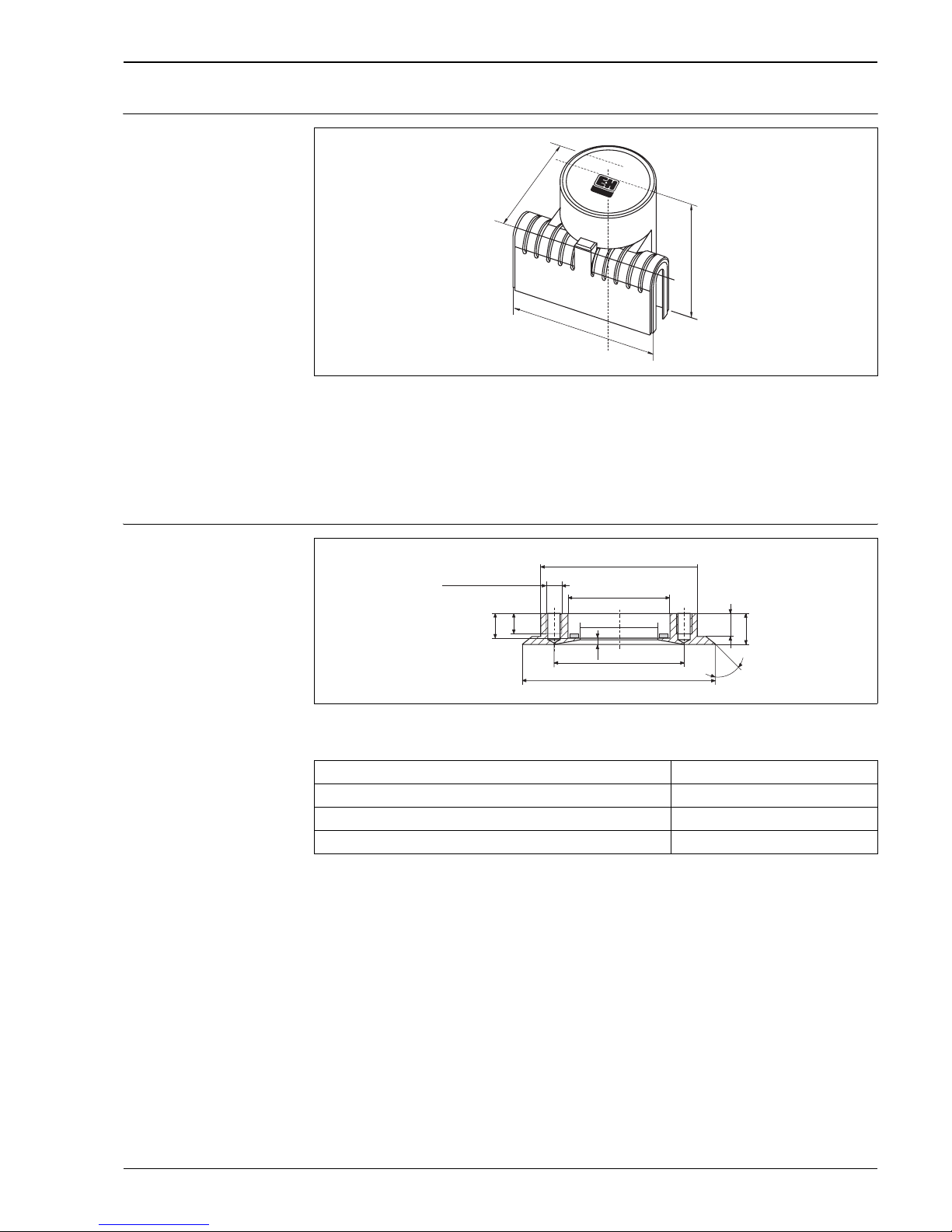
Deltapilot S
Endress+Hauser 57
Protective cover
P01-DB5xxxxx-00-xx-xx-xx-001
Protection cover
For the aluminum and polyester housing, Endress+Hauser offers protective covers with two cable entries.
• Max. ambient temperature: +70°C (+158°F)
• Material: polyamide (PA)
• Order number for protection cover for devices with a flat cover: 942262-0000
• Order number for protection cover for devices with a high cover: 942262-0001
Welding flanges
P01-DB5xxxxx-06-xx-xx-xx-032
Welding flange for flush-mounted installation for devices with a DRD flange.
Note!
• Order number for a replacement PTFE flat seal: 916783-0000
110
137
155
ø125
ø50
ø66
ø105
45°
3
13
16
15
20
4xM10
4 x 90° (= 360°)
ø84
Version Order number
DRD DN 50, AISI 316L (1.4435) 52002041
DRD DN 50, 3.1, AISI 304 (1.4301) 52011899
DRD DN 50, AISI 304 (1.4301) 916743-0000
Page 58
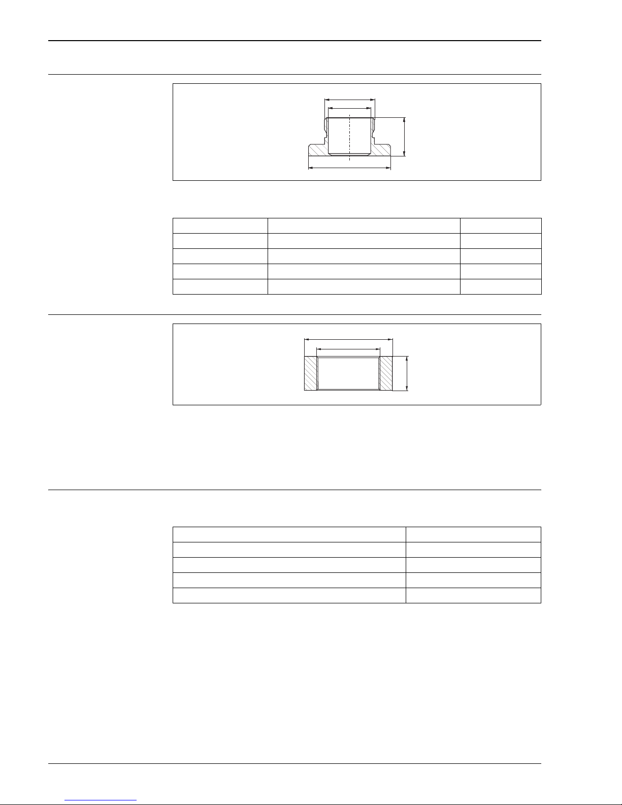
Deltapilot S
58 Endress+Hauser
Welding neck adapter for
universal process adapter
P01-PMC45xxx-06-xx -xx-xx-000
Welding neck adapter for flush mounting a Deltapilot S DB50L/DB50S with a universal process adapter
Welding neck adapter thread
ISO G 1 1/2
P01-PMx4xxxx-06-09 -xx-xx-000
Welding neck adapter for flush mounting a Deltapilot S DB50 with thread ISO 228 G 1 1/2 A
Order number: 52024469, order number with 3.1 inspection certificate: 52024470
Note!
• Endress+Hauser offers a pressure sensor dummy for the welding necks with order numbers 52024469 and
52024470. Order number for pressure sensor dummy: 52024471
Adapter You can use the following adapters to mount a DB50L with a universal process connection in a DRD, dairy
fitting or Clamp connection:
ø44
39.5
Rd 52 x 1/6
D
Diameter D Material Order number
65 mm AISI 316L 214880-0002
65 mm AISI 316L with inspection certificate EN 10204 3.1 material 52010174
85 mm AISI 316L 52006262
85 mm AISI 316L with inspection certificate EN 10204 3.1 material 52010173
ø65
25
G 1 1/2
Version Order number
DRD 65 mm, AISI 304 (1.4301) 917656-0001
Dairy fitting DIN 11851 DN 40, AISI 304 (1.4301) 917656-0002
Dairy fitting DIN 11851 DN 50, AISI 304 (1.4301) 917656-0000
Tri-Clamp ISO 2852 DN 40-51 (2")/DIN 32676 DN 50, AISI 304 (1.4301) 917650-0002
Page 59

Deltapilot S
Endress+Hauser 59
Documentation
Field of Activities • Pressure measurement, powerful measuring devices for process pressure, differential pressure, level and
flow: FA004P/00/en
Technical Information on
switching unit
• Level measurement, silometer FMC4120: TI077F/00/en
• Level measurement, Prolevel FMB662: TI234F/00/en
Operating Instructions • Deltapilot S HART: BA152P/00/en
• Deltapilot S PROFIBUS PA: BA164F/00/en
• Deltapilot S FOUNDATION Fieldbus: BA232F/00/en
• PROFIBUS DP/PA, Guidelines for planning and commissioning: BA034S/04/en
• FOUNDATION Fieldbus Overview, Installation and Commissioning Guidelines: BA013S/04/en
Safety Instructions
Installation Drawings/
Control Drawings
Overfill protection • WHG: ZE217F/00/en: HART
• WHG: ZE238F/00/en: PROFIBUS PA
Certificate/explosion
protection
Device Electronics Documentation
ATEX II 1/2 G EEx ia IIC T6 DB50, DB50L,
DB51, DB52
–PFM
–4 to 20 mA HART
– PROFIBUS PA
– FOUNDATION
Fieldbus
– XA002F
– XA002F
– XA007F
– XA135F
ATEX II 2 G EEx ia IIC T6 DB53 – PFM
–4 to 20 mA HART
– PROFIBUS PA
– FOUNDATION
Fieldbus
– XA002F
– XA002F
– XA007F
– XA135F
ATEX 1/2 G EEx nA II T6 DB50, DB50L,
DB51, DB52,
DB53
–PFM
–4 to 20 mA HART
– PROFIBUS PA
– FOUNDATION
Fieldbus
– XA189F
– XA189F
– XA189F
– XA189F
ATEX II 1/2 G EEx ia IIB T6 DB52 – PFM
–4 to 20 mA HART
– PROFIBUS PA
– FOUNDATION
Fieldbus
– XA002F
– XA002F
– XA007F
– XA135F
Certificate/explosion
protection
Device Electronics Documentation
CSA IS Class I, Division 1,
Groups A-D
DB50(A),
DB50L, DB50S,
DB51(A), DB 52(A),
DB53(A)
–PFM
–4 to 20 mA HART
– PROFIBUS PA
– FOUNDATION
Fieldbus
– Order number: 016586-0000
– Order number: 960351-1034
– ZD036F + ZD021F
– ZD068F + ZD021F
FM IS Class I, Division 1, 2
Groups A-D
DB50A, DB50S,
DB51A, DB52A,
DB53A
–PFM
–4 to 20 mA HART
– PROFIBUS PA
– FOUNDATION
Fieldbus
– Order number: 017054-0000
– Order number: 017054-0000
– ZD024F + ZD021F
– ZD067F + ZD021F
Page 60

Deltapilot S
Deutschland Österreich Schweiz
Endress+Hauser
Messtechnik
GmbH+Co. KG
Colmarer Str. 6
79576 Weil am Rhein
Fax 0800 EHFAXEN
Fax 0800 3 43 29 36
www.de.endress.com
Vertrieb
• Beratung
• Information
• Auftrag
• Bestellung
Tel. 0800 EHVERTRIEB
Tel. 0800 3 48 37 87
[email protected]
Service
• Help-Desk
• Feldservice
• Ersatzteile/Reparatur
• Kalibrierung
Tel. 0800 EHSERVICE
Tel. 0800 3 47 37 84
[email protected]
Technische Büros
• Hamburg
• Hannover
• Ratingen
• Frankfurt
• Stuttgart
• München
• Berlin
Endress+Hauser
Ges.m.b.H.
Lehnergasse 4
1230 Wien
Tel. +43 1 88 05 60
Fax +43 1 88 05 63 35
[email protected]
www.at.endress.com
Endress+Hauser
Metso AG
Sternenhofstraße 21
4153 Reinach/BL 1
Tel. +41 61 7 15 75 75
Fax +41 61 7 11 16 50
[email protected]
www.ch.endress.com
TI257P/00/en/10.06
71034474
CCS/FM+SGML 6.0
71034474
 Loading...