

Endress+Hauser Deltapilot M FMB50, Deltapilot M FMB52, Deltapilot M FMB53, Deltapilot M FMB51, Cerabar M PMC51 Brief Operating Instructions
...Page 1
KA01035P/00/EN/05.16
71316893
Products Solutions Services
Brief Operating Instructions
Deltapilot M FMB50, FMB51,
FMB52, FMB53
Hydrostatic level measurement
These Instructions are Brief Operating Instructions; they are not
a substitute for the Operating Instructions pertaining to the
device.
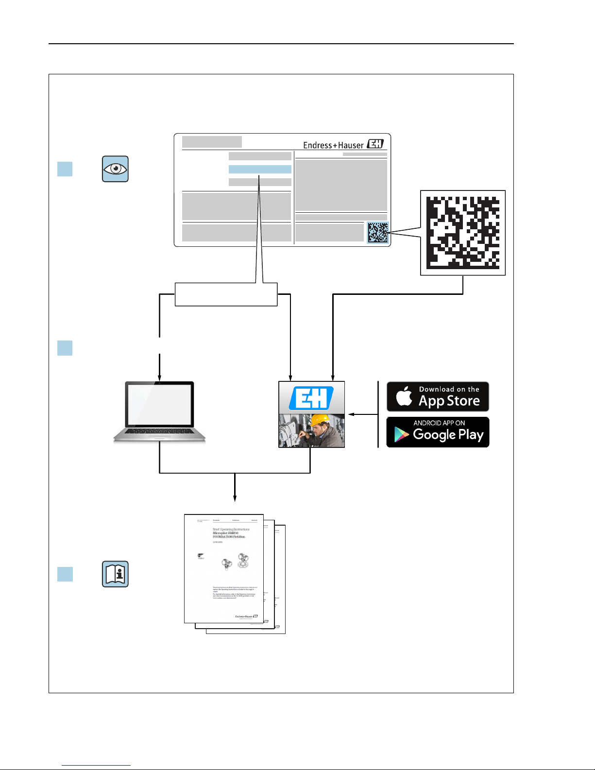
Detailed information about the device can be found in the Operating Instructions and the other documentation:
Available for all device versions via:
– Internet: www.endress.com/deviceviewer
– Smart phone/tablet: Endress+Hauser Operations App
Page 2
Deltapilot M FOUNDATION Fieldbus
1.
Order code:
Ext. ord. cd.:
Ser. no.:
www.endress.com/deviceviewer Endress+Hauser Operations App
XXXXXXXXXXXX
XXXXX-XXXXXX
XXX.XXXX.XX
Serial number
2.
3.
2 Endress+Hauser
A0023555
Page 3

Deltapilot M FOUNDATION Fieldbus Table of contents
Table of contents
1 Document information . . . . . . . . . . . . . . . . . . . . . . . . . . . . . . . . . . . . . . . . . . . . . . . . . . . . . . . . . 4
1.1 Document function . . . . . . . . . . . . . . . . . . . . . . . . . . . . . . . . . . . . . . . . . . . . . . . . . . . . . . . . . . . . . . . . . . . . . . . . . . . . . . . . . . 4
1.2 Symbols used . . . . . . . . . . . . . . . . . . . . . . . . . . . . . . . . . . . . . . . . . . . . . . . . . . . . . . . . . . . . . . . . . . . . . . . . . . . . . . . . . . . . . . . 4
2 Basic safety instructions . . . . . . . . . . . . . . . . . . . . . . . . . . . . . . . . . . . . . . . . . . . . . . . . . . . . . . . . 6
2.1 Requirements concerning the staff . . . . . . . . . . . . . . . . . . . . . . . . . . . . . . . . . . . . . . . . . . . . . . . . . . . . . . . . . . . . . . . . . . . . . 6
2.2 Designated use . . . . . . . . . . . . . . . . . . . . . . . . . . . . . . . . . . . . . . . . . . . . . . . . . . . . . . . . . . . . . . . . . . . . . . . . . . . . . . . . . . . . . . 7
2.3 Workplace safety . . . . . . . . . . . . . . . . . . . . . . . . . . . . . . . . . . . . . . . . . . . . . . . . . . . . . . . . . . . . . . . . . . . . . . . . . . . . . . . . . . . . 7
2.4 Operational safety . . . . . . . . . . . . . . . . . . . . . . . . . . . . . . . . . . . . . . . . . . . . . . . . . . . . . . . . . . . . . . . . . . . . . . . . . . . . . . . . . . . 7
2.5 Hazardous area . . . . . . . . . . . . . . . . . . . . . . . . . . . . . . . . . . . . . . . . . . . . . . . . . . . . . . . . . . . . . . . . . . . . . . . . . . . . . . . . . . . . . 8
2.6 Product safety . . . . . . . . . . . . . . . . . . . . . . . . . . . . . . . . . . . . . . . . . . . . . . . . . . . . . . . . . . . . . . . . . . . . . . . . . . . . . . . . . . . . . . . 8
3 Identification. . . . . . . . . . . . . . . . . . . . . . . . . . . . . . . . . . . . . . . . . . . . . . . . . . . . . . . . . . . . . . . . . . 8
3.1 Product identification . . . . . . . . . . . . . . . . . . . . . . . . . . . . . . . . . . . . . . . . . . . . . . . . . . . . . . . . . . . . . . . . . . . . . . . . . . . . . . . . 8
3.2 Scope of delivery . . . . . . . . . . . . . . . . . . . . . . . . . . . . . . . . . . . . . . . . . . . . . . . . . . . . . . . . . . . . . . . . . . . . . . . . . . . . . . . . . . . . 8
3.3 CE mark, Declaration of Conformity . . . . . . . . . . . . . . . . . . . . . . . . . . . . . . . . . . . . . . . . . . . . . . . . . . . . . . . . . . . . . . . . . . . . 9
4 Installation . . . . . . . . . . . . . . . . . . . . . . . . . . . . . . . . . . . . . . . . . . . . . . . . . . . . . . . . . . . . . . . . . . . 9
4.1 Incoming acceptance . . . . . . . . . . . . . . . . . . . . . . . . . . . . . . . . . . . . . . . . . . . . . . . . . . . . . . . . . . . . . . . . . . . . . . . . . . . . . . . . . 9
4.2 Storage and transport . . . . . . . . . . . . . . . . . . . . . . . . . . . . . . . . . . . . . . . . . . . . . . . . . . . . . . . . . . . . . . . . . . . . . . . . . . . . . . . . 9
4.3 Installation conditions . . . . . . . . . . . . . . . . . . . . . . . . . . . . . . . . . . . . . . . . . . . . . . . . . . . . . . . . . . . . . . . . . . . . . . . . . . . . . . . . 9
4.4 General installation instructions . . . . . . . . . . . . . . . . . . . . . . . . . . . . . . . . . . . . . . . . . . . . . . . . . . . . . . . . . . . . . . . . . . . . . . 10
4.5 Installing . . . . . . . . . . . . . . . . . . . . . . . . . . . . . . . . . . . . . . . . . . . . . . . . . . . . . . . . . . . . . . . . . . . . . . . . . . . . . . . . . . . . . . . . . . 10
4.6 Mounting of the profile seal for universal process mounting adapter . . . . . . . . . . . . . . . . . . . . . . . . . . . . . . . . . . . . . . . 16
4.7 Closing the housing cover . . . . . . . . . . . . . . . . . . . . . . . . . . . . . . . . . . . . . . . . . . . . . . . . . . . . . . . . . . . . . . . . . . . . . . . . . . . . 16
4.8 Post-installation check . . . . . . . . . . . . . . . . . . . . . . . . . . . . . . . . . . . . . . . . . . . . . . . . . . . . . . . . . . . . . . . . . . . . . . . . . . . . . . 17
5 Electrical connection . . . . . . . . . . . . . . . . . . . . . . . . . . . . . . . . . . . . . . . . . . . . . . . . . . . . . . . . . . 17
5.1 Connecting the device . . . . . . . . . . . . . . . . . . . . . . . . . . . . . . . . . . . . . . . . . . . . . . . . . . . . . . . . . . . . . . . . . . . . . . . . . . . . . . . 17
5.2 Connecting the measuring unit . . . . . . . . . . . . . . . . . . . . . . . . . . . . . . . . . . . . . . . . . . . . . . . . . . . . . . . . . . . . . . . . . . . . . . . 19
5.3 Potential equalization . . . . . . . . . . . . . . . . . . . . . . . . . . . . . . . . . . . . . . . . . . . . . . . . . . . . . . . . . . . . . . . . . . . . . . . . . . . . . . . 20
5.4 Overvoltage protection (optional) . . . . . . . . . . . . . . . . . . . . . . . . . . . . . . . . . . . . . . . . . . . . . . . . . . . . . . . . . . . . . . . . . . . . . 20
5.5 Post-connection check . . . . . . . . . . . . . . . . . . . . . . . . . . . . . . . . . . . . . . . . . . . . . . . . . . . . . . . . . . . . . . . . . . . . . . . . . . . . . . 20
6 Operation. . . . . . . . . . . . . . . . . . . . . . . . . . . . . . . . . . . . . . . . . . . . . . . . . . . . . . . . . . . . . . . . . . . .20
6.1 Operating options . . . . . . . . . . . . . . . . . . . . . . . . . . . . . . . . . . . . . . . . . . . . . . . . . . . . . . . . . . . . . . . . . . . . . . . . . . . . . . . . . . 20
6.2 Operation without an operating menu . . . . . . . . . . . . . . . . . . . . . . . . . . . . . . . . . . . . . . . . . . . . . . . . . . . . . . . . . . . . . . . . 22
6.3 Operation with an operating menu . . . . . . . . . . . . . . . . . . . . . . . . . . . . . . . . . . . . . . . . . . . . . . . . . . . . . . . . . . . . . . . . . . . . 24
6.4 FOUNDATION Fieldbus communication protocol . . . . . . . . . . . . . . . . . . . . . . . . . . . . . . . . . . . . . . . . . . . . . . . . . . . . . . . . 31
7 Commissioning without an operating menu. . . . . . . . . . . . . . . . . . . . . . . . . . . . . . . . . . . . . . . 31
7.1 Function check . . . . . . . . . . . . . . . . . . . . . . . . . . . . . . . . . . . . . . . . . . . . . . . . . . . . . . . . . . . . . . . . . . . . . . . . . . . . . . . . . . . . . 32
7.2 Position adjustment . . . . . . . . . . . . . . . . . . . . . . . . . . . . . . . . . . . . . . . . . . . . . . . . . . . . . . . . . . . . . . . . . . . . . . . . . . . . . . . . . 32
8 Commissioning with an operating menu (onsite display/FieldCare) . . . . . . . . . . . . . . . . . .33
8.1 Function check . . . . . . . . . . . . . . . . . . . . . . . . . . . . . . . . . . . . . . . . . . . . . . . . . . . . . . . . . . . . . . . . . . . . . . . . . . . . . . . . . . . . . 33
8.2 Commissioning . . . . . . . . . . . . . . . . . . . . . . . . . . . . . . . . . . . . . . . . . . . . . . . . . . . . . . . . . . . . . . . . . . . . . . . . . . . . . . . . . . . . . 34
8.3 Pos. zero adjust . . . . . . . . . . . . . . . . . . . . . . . . . . . . . . . . . . . . . . . . . . . . . . . . . . . . . . . . . . . . . . . . . . . . . . . . . . . . . . . . . . . . 35
8.4 Level measurement . . . . . . . . . . . . . . . . . . . . . . . . . . . . . . . . . . . . . . . . . . . . . . . . . . . . . . . . . . . . . . . . . . . . . . . . . . . . . . . . 36
8.5 Linearization . . . . . . . . . . . . . . . . . . . . . . . . . . . . . . . . . . . . . . . . . . . . . . . . . . . . . . . . . . . . . . . . . . . . . . . . . . . . . . . . . . . . . . 46
8.6 Pressure measurement . . . . . . . . . . . . . . . . . . . . . . . . . . . . . . . . . . . . . . . . . . . . . . . . . . . . . . . . . . . . . . . . . . . . . . . . . . . . . . 46
Endress+Hauser 3
Page 4
Document information Deltapilot M FOUNDATION Fieldbus
DANGER
WARNING
CAUTION
NOTICE
)
1 Document information
1.1 Document function
These Operating Instructions contain all the information that is required in various phases of
the life cycle of the device: from product identification, incoming acceptance and storage, to
mounting, connection, operation and commissioning through to troubleshooting, maintenance
and disposal.
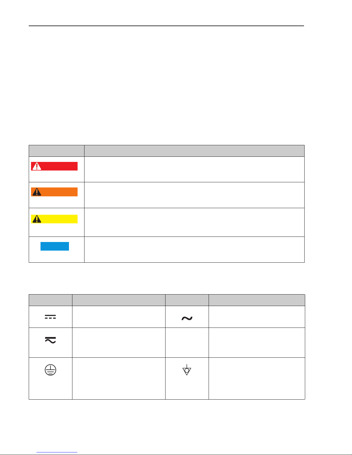
1.2 Symbols used
1.2.1 Safety symbols
Symbol Meaning
DANGER!
This symbol alerts you to a dangerous situation. Failure to avoid this situation will result in
A0011189-DE
seriousor fatal injury.
WARNING!
This symbol alerts you to a dangerous situation. Failure to avoid this situation can result in
A0011190-DE
A0011191-DE
A0011192-DE
seriousor fatal injury.
CAUTION!
This symbol alerts you to a dangerous situation. Failure to avoid this situation can result in
minoror medium injury.
NOTICE!
This symbol contains information on procedures and other facts which do not result in
personalinjury.
1.2.2 Electrical symbols
Symbol Meaning Symbol Meaning
Direct current Alternating current
Direct current and alternating current Ground connection
A grounded terminal which, as far as the
operator is concerned, is grounded via a
grounding system.
Protective ground connection
A terminal which must be connected to
ground prior to establishing any other
connections.
4 Endress+Hauser
Equipotential connection
A connection that has to be connected to
the plant grounding system: This may be
a potential equalization line or a star
grounding system depending on
national or company codes of practice.
Page 5
Deltapilot M FOUNDATION Fieldbus Document information
1.
2.
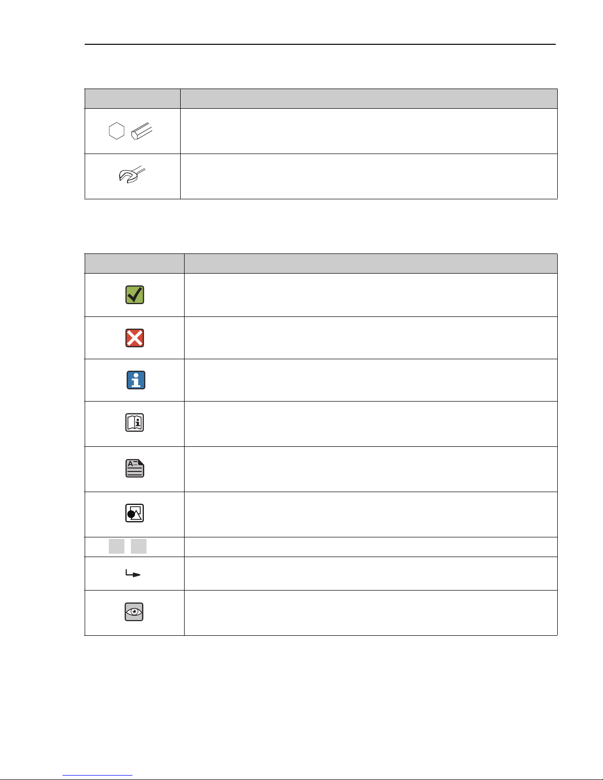
1.2.3 Tool symbols
Symbol Meaning
Allen key
A0011221
Hexagon wrench
A0011222
1.2.4 Symbols for certain types of information
Symbol Meaning
Permitted
Indicates procedures, processes or actions that are permitted.
A0011182
Forbidden
Indicates procedures, processes or actions that are forbidden.
A0011184
Tip
Indicates additional information.
A0011193
Reference to documentation
A0015482
Reference to page
A0015484
Reference to graphic
A0015487
, , ... Series of steps
Result of a sequence of actions
A0018343
Visual inspection
A0015502
Endress+Hauser 5
Page 6
Basic safety instructions Deltapilot M FOUNDATION Fieldbus
1.
2.
t 85°C>
1.2.5 Symbols in graphics
Symbol Meaning
1, 2, 3, 4, ... Item numbers
, , ... Series of steps
A, B, C, D, ... Views
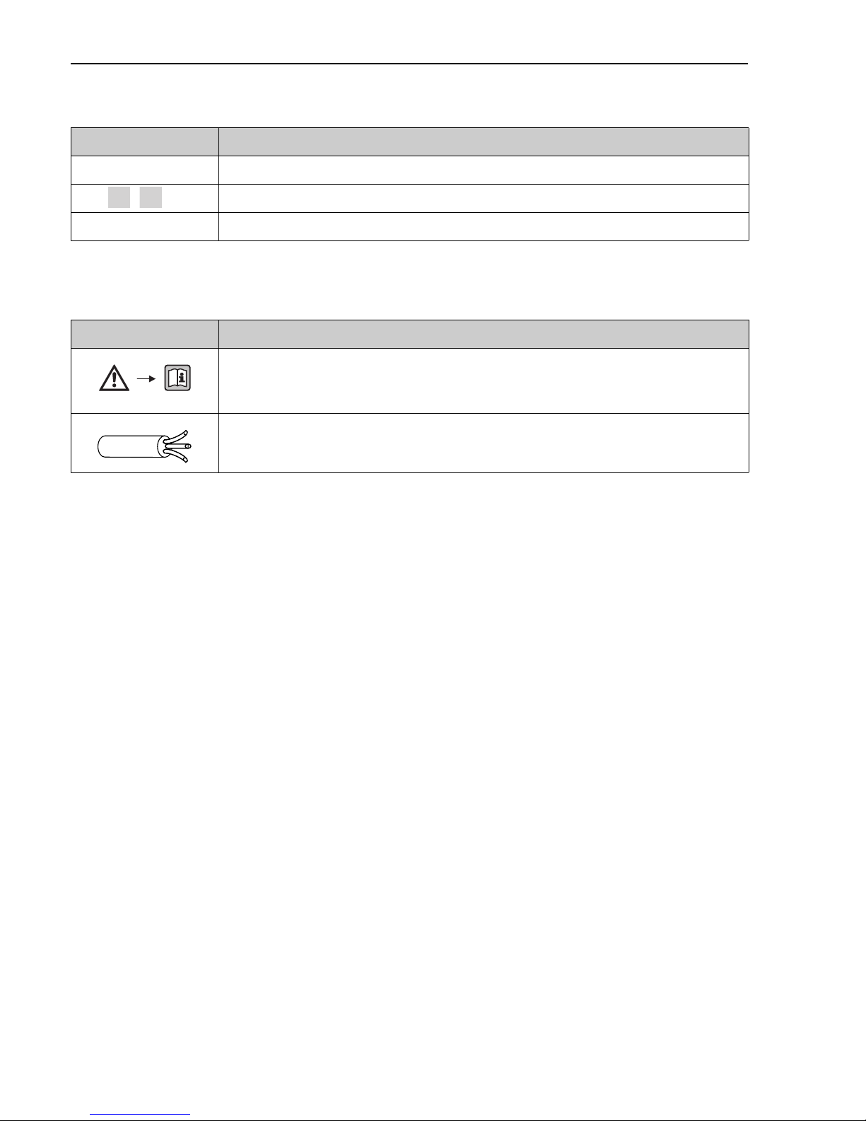
1.2.6 Symbols at the device
Symbol Meaning
Safety instructions
Observe the safety instructions contained in the associated Operating Instructions.
A0019159
Connecting cable immunity to temperature change
Indicates that the connecting cables have to withstand a temperature of 85°C at least.
1.2.7 Registered trademarks
KALREZ®, VITON®, TEFLON
®
Registered label of E.I. Du Pont de Nemours & Co., Wilmington, USA
TRI-CLAMP
®
Registered label of Ladish & Co., Inc., Kenosha, USA
FOUNDATIONTM Fieldbus
Registered trademark of the FieldComm Group, Austin, USA
GORE-TEX
®
Registered label of W.L. Gore & Associates, Inc., USA
2 Basic safety instructions
2.1 Requirements concerning the staff
The personnel for installation, commissioning, diagnostics and maintenance must fulfill the
following requirements:
• Trained, qualified specialists: must have a relevant qualification for this specific function and
task
• Are authorized by the plant owner/operator
• Are familiar with federal/national regulations
6 Endress+Hauser
Page 7

Deltapilot M FOUNDATION Fieldbus Basic safety instructions
• Before beginning work, the specialist staff must have read and understood the instructions in
the Operating Instructions and supplementary documentation as well as in the certificates
(depending on the application)
• Following instructions and basic conditions
The operating personnel must fulfill the following requirements:
• Being instructed and authorized according to the requirements of the task by the facility's
owner-operator
• Following the instructions in these Operating Instructions
2.2 Designated use
The Deltapilot M is a hydrostatic pressure sensor for measuring level and pressure.
2.2.1 Incorrect use
The manufacturer is not liable for damage caused by improper or non-designated use.
Verification for borderline cases:
For special fluids and fluids for cleaning, Endress+Hauser is glad to provide assistance in
verifying the corrosion resistance of fluid-wetted materials, but does not accept any warranty or
liability.
2.3 Workplace safety
For work on and with the device:
• Wear the required personal protective equipment according to federal/national regulations.
• Switch off the supply voltage before connecting the device.
2.4 Operational safety
Risk of injury!
‣ Operate the device in proper technical condition and fail-safe condition only.
‣ The operator is responsible for interference-free operation of the device.
‣ Only disassemble the device in pressurless condition!
Conversions to the device
Unauthorized modifications to the device are not permitted and can lead to unforeseeable
dangers:
‣ If, despite this, modifications are required, consult with Endress+Hauser.
Repair
To ensure continued operational safety and reliability,
‣ Carry out repairs on the device only if they are expressly permitted.
‣ Observe federal/national regulations pertaining to repair of an electrical device.
‣ Use original spare parts and accessories from Endress+Hauser only.
Endress+Hauser 7
Page 8

Identification Deltapilot M FOUNDATION Fieldbus
2.5 Hazardous area
To eliminate a danger for persons or for the facility when the device is used in the hazardous
area (e.g. explosion protection, pressure vessel safety):
• Based on the nameplate, check whether the ordered device is permitted for the intended use
in the hazardous area.
• Observe the specifications in the separate supplementary documentation that is an integral
part of these Instructions.
2.6 Product safety
This measuring device is designed in accordance with good engineering practice to meet
state-of-the- art safety requirements, has been tested, and left the factory in a condition in
which they are safe to operate. It fulfills general safety requirements and legal requirements. It
also conforms to the EC directives listed in the device-specific EC declaration of conformity.
Endress+Hauser confirms this fact by applying the CE mark.
3 Identification
3.1 Product identification
The following options are available for identification of the measuring device:
• Nameplate specifications
• Order code with breakdown of the device features on the delivery note
• Enter serial numbers from nameplates in W@M Device Viewer
(www.endress.com/deviceviewer): All information about the measuring device is displayed.
For an overview of the technical documentation provided, enter the serial number from the
nameplates in the W@M Device Viewer (www.endress.com/deviceviewer).
3.2 Scope of delivery
The scope of delivery comprises:
• Device
• Optional accessories
Documentation supplied:
• The Operating Instructions BA00384P is available on the Internet.
See: www.endress.com Download
• Brief Operating Instructions: KA01035P Deltapilot M
• Final inspection report
• Additional Safety Instructions for ATEX, IECEx and NEPSI devices
• Optional: factory calibration form, test certificates
8 Endress+Hauser
Page 9

Deltapilot M FOUNDATION Fieldbus Installation
WARNING
!
3.3 CE mark, Declaration of Conformity
The devices are designed to meet state-of-the-art safety requirements, have been tested and left
the factory in a condition in which they are safe to operate. The devices comply with the
applicable standards and regulations as listed in the EC Declaration of Conformity and thus
comply with the statutory requirements of the EC Directives. Endress+Hauser confirms the
conformity of the device by affixing to it the CE mark.
4 Installation
4.1 Incoming acceptance
• Check the packaging and the contents for damage.
• Check the shipment, make sure nothing is missing and that the scope of supply matches your
order.
4.2 Storage and transport
4.2.1 Storage
The device must be stored in a dry, clean area and protected against damage from impact (EN
837-2).
Storage temperature range:
See Technical Information for Deltapilot M TI00437P.
4.2.2 Transport
Incorrect transportation
Housing, diaphragm and capillaries may become damaged, and there is a risk of injury!
‣ Transport the measuring device to the measuring point in its original packaging or by the
process connection.
‣ Follow the safety instructions and transport conditions for devices weighing more than 18
kg (39.6 lbs).
‣ Do not use capillaries as a carrying aid for the diaphragm seals.
4.3 Installation conditions
4.3.1 Dimensions
For dimensions, please refer to the Technical Information for Deltapilot M TI00437P,
"Mechanical construction" section.
Endress+Hauser 9
Page 10

Installation Deltapilot M FOUNDATION Fieldbus
WARNING
!
WARNING
!
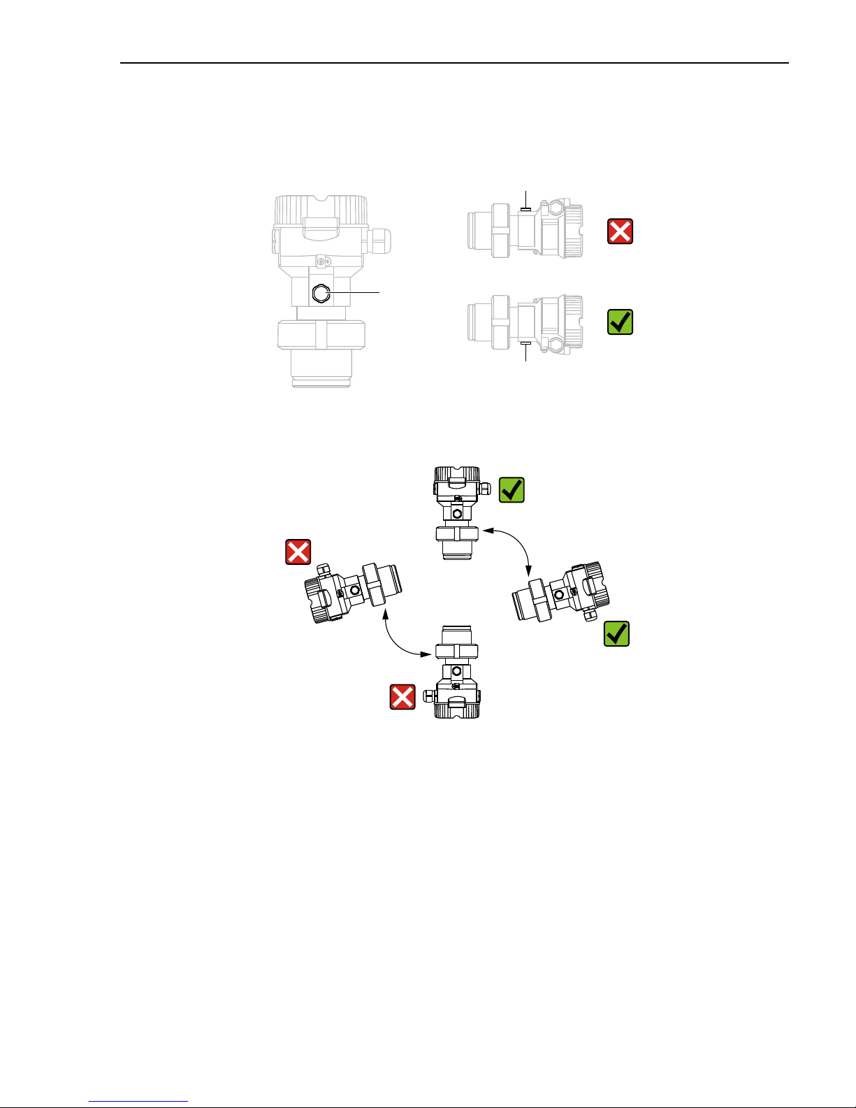
4.4 General installation instructions
• Devices with a G 1 1/2 thread:
When screwing the device into the tank, the flat seal has to be positioned on the sealing
surface
of the process connection. To avoid additional strain on the process isolating diaphragm, the
thread should never be sealed with hemp or similar materials.
• Devices with NPT threads:
– Wrap Teflon tape around the thread to seal it.
– Tighten the device at the hexagonal bolt only. Do not turn at the housing.
– Do not overtighten the thread when screwing. Max. torque: 20 to 30 Nm (14.75 to 22.13
lbf ft)
4.4.1 Mounting sensor modules with PVDF thread
Risk of damage to process connection!
Risk of injury!
‣ Sensor modules with PVDF process connections with threaded connection must be installed
with the mounting bracket provided!
Material fatigue from pressure and temperature!
Risk of injury if parts burst! The thread can become loose if exposed to high pressure and
temperatures.
‣ The integrity of the thread must be checked regularly and the thread may need to be
re-tightened with the maximum tightening torque of 7 Nm (5.16 lbf ft). Teflon tape is
recommended for sealing the ½" NPT thread.
4.5 Installing
• Due to the orientation of the Deltapilot M, there may be a shift in the zero point, i.e. when the
container is empty or partially full, the measured value does not display zero. You can correct
this zero point shift ä 23, Section "Function of the operating elements" or ä 35,
Section 8.3 "Pos. zero adjust".
• The local display can be rotated in 90° stages.
• Endress+Hauser offers a mounting bracket for installing on pipes or walls.
ä 14, Section 4.5.6 " "Wall and pipe mounting (optional)".
4.5.1 General installation instructions
• Do not clean or touch process isolating diaphragms with hard or pointed objects.
• The process isolating diaphragm in the rod and cable version is protected against mechanical
damage by a plastic cap.
10 Endress+Hauser
Page 11
Deltapilot M FOUNDATION Fieldbus Installation
1
1
1
• If a heated Deltapilot M is cooled during the cleaning process (e.g. by cold water), a vacuum
develops for a short time, whereby moisture can penetrate the sensor through the pressure
compensation (1). If this is the case, mount the Deltapilot M with the pressure compensation
(1) pointing downwards.
• Keep the pressure compensation and GORE-TEX® filter (1) free from contamination.
• The device must be installed as follows in order to comply with the cleanability requirements
of the ASME-BPE (Part SD Cleanibility).:
4.5.2 FMB50
Level measurement
• Always install the device below the lowest measuring point.
• Do not install the device at the following positions:
– in the filling curtain
– in the tank outflow
– in the suction area of a pump
– or at a point in the tank that can be affected by pressure pulses from the agitator
• The calibration and functional test can be carried out more easily if you mount the device
downstream of a shutoff device.
• Deltapilot M must be included in the insulation for media that can harden when cold.
Endress+Hauser 11
Page 12
Installation Deltapilot M FOUNDATION Fieldbus
L
E
17 (0.67)
Pressure measurement in gases
• Mount Deltapilot M with shutoff device above the tapping point so that any condensate can
flow into the process.
Pressure measurement in steams
• Mount Deltapilot M with siphon above the tapping point.
• Fill the siphon with liquid before commissioning.
The siphon reduces the temperature to almost the ambient temperature.
Pressure measurement in liquids
• Mount Deltapilot M with the shutoff device below or at the same level as the tapping point.
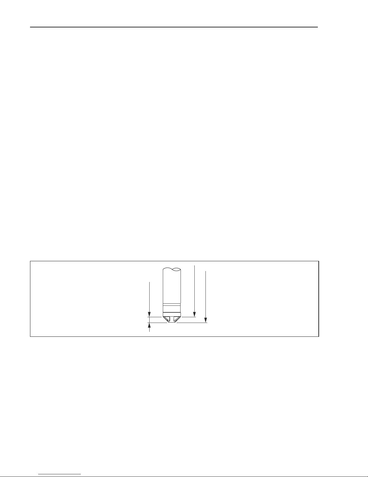
4.5.3 FMB51/FMB52/FMB53
• When mounting rod and cable versions, make sure that the probe head is located at a point
as free as possible from flow. To protect the probe from impact resulting from lateral
movement, mount the probe in a guide tube (preferably made of plastic) or secure it with a
clamping fixture.
• In the case of devices for hazardous areas, comply strictly with the safety instructions when
the housing cover is open.
• The length of the extension cable or the probe rod is based on the planned level zero point.
The height of the protective cap must be taken into consideration when designing the layout
of the measuring point. The level zero point (E) corresponds to the position of the process
isolating diaphragm.
Level zero point = E; top of the probe = L.
12 Endress+Hauser
Page 13
Deltapilot M FOUNDATION Fieldbus Installation
1
2
3
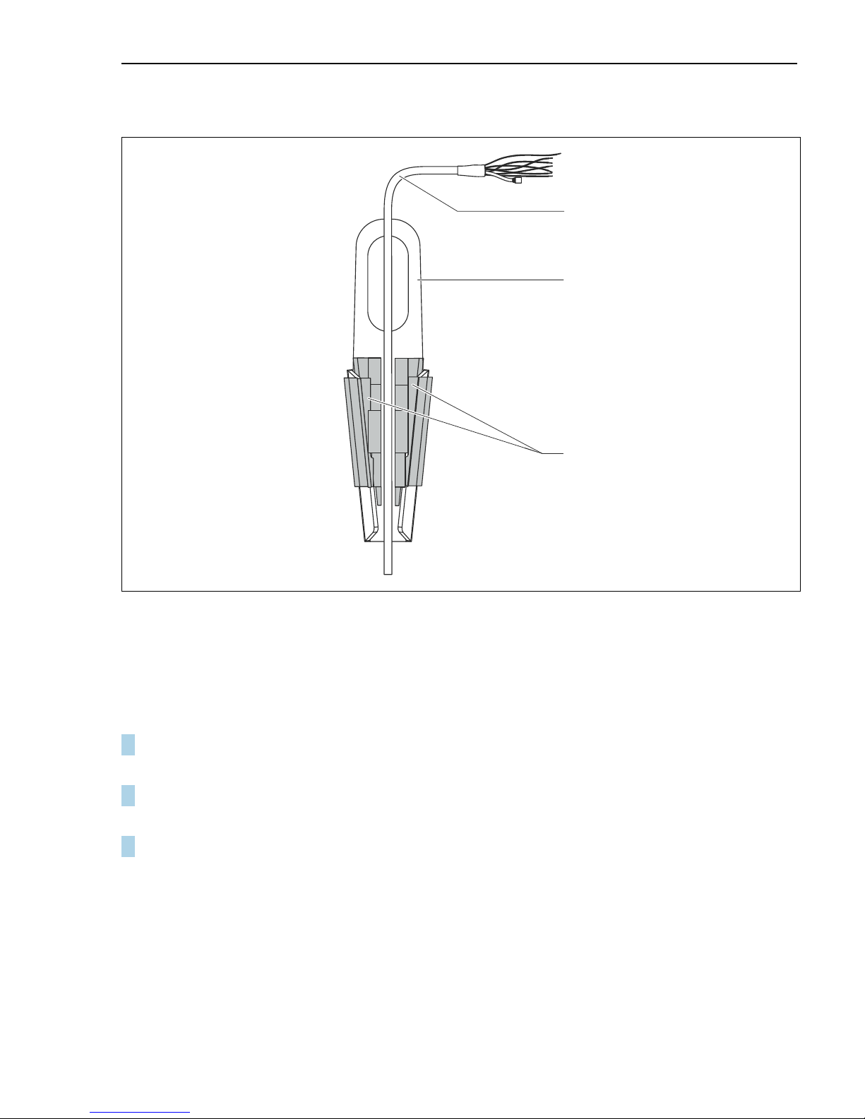
4.5.4 Mounting the FMB53 with a suspension clamp
Fig. 1: Mounting with a suspension clamp
1Extension cable
2 Suspension clamp
3 Clamping jaws
A0018793
Mounting the suspension clamp:
1. Mount the suspension clamp (item 2). When selecting the place to fix the unit, take the
weight of the extension cable (item 1) and the device into account.
2. Raise the clamping jaws (item 3). Position the extension cable (item 1) between the
clamping jaws as illustrated in Figure.
3. Hold the extension cable in position (item 1) and push the clamping jaws (item 3) back
down.
Tap the clamping jaws gently from above to fix them in place.
Endress+Hauser 13
Page 14
Installation Deltapilot M FOUNDATION Fieldbus
NOTICE
12
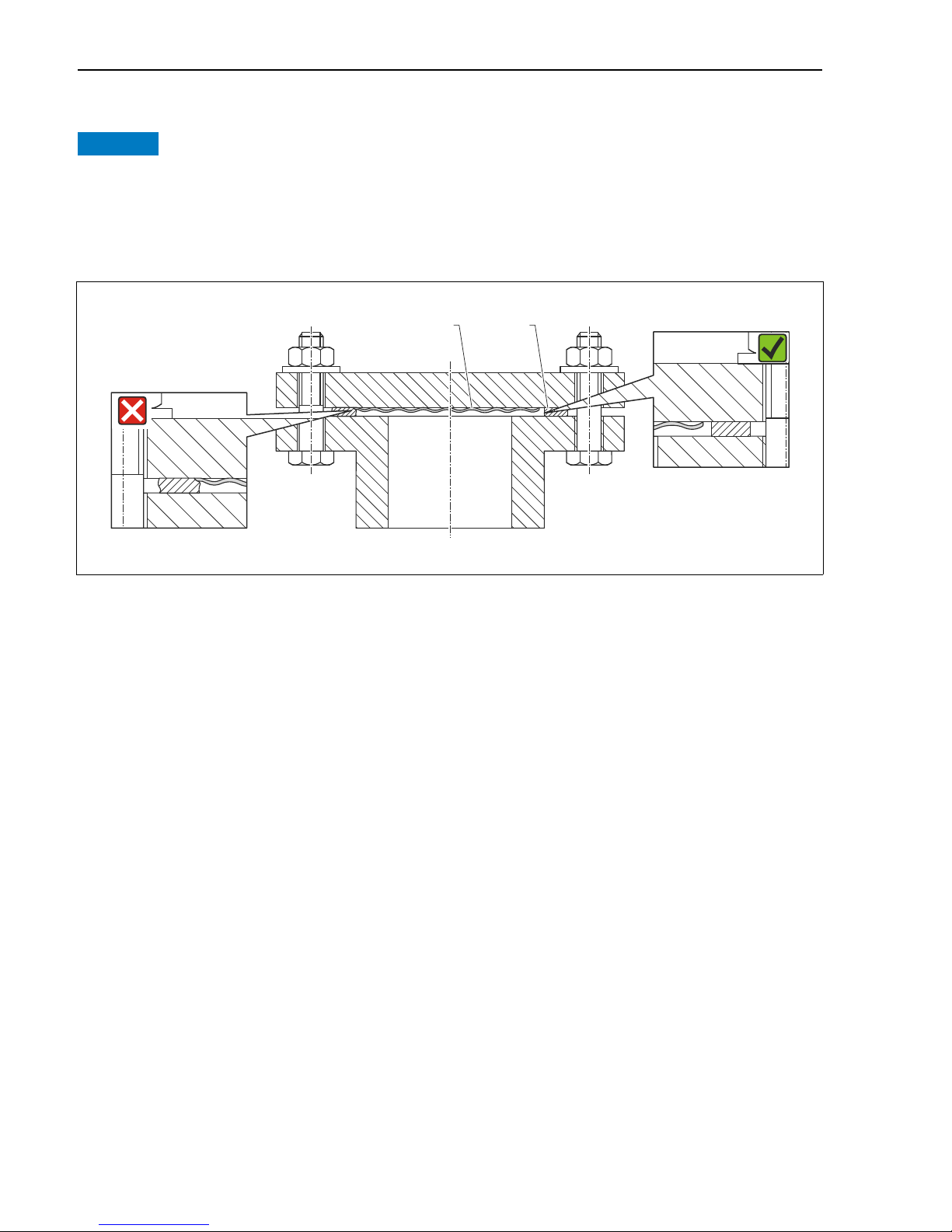
4.5.5 Seal for flange mounting
Distorted measurement results.
The seal is not allowed to press on the process isolating diaphragm as this could affect the
measurement result.
‣ Ensure that the seal is not touching the process isolating diaphragm.
Fig. 2:
1 Process isolating diaphragm
2Seal
4.5.6 Wall and pipe mounting (optional)
Mounting bracket
See operating instructions.
A0017743
14 Endress+Hauser
Page 15
Deltapilot M FOUNDATION Fieldbus Installation
r ³ 120 (4.72)
2
3
4
5
6
1
7
7
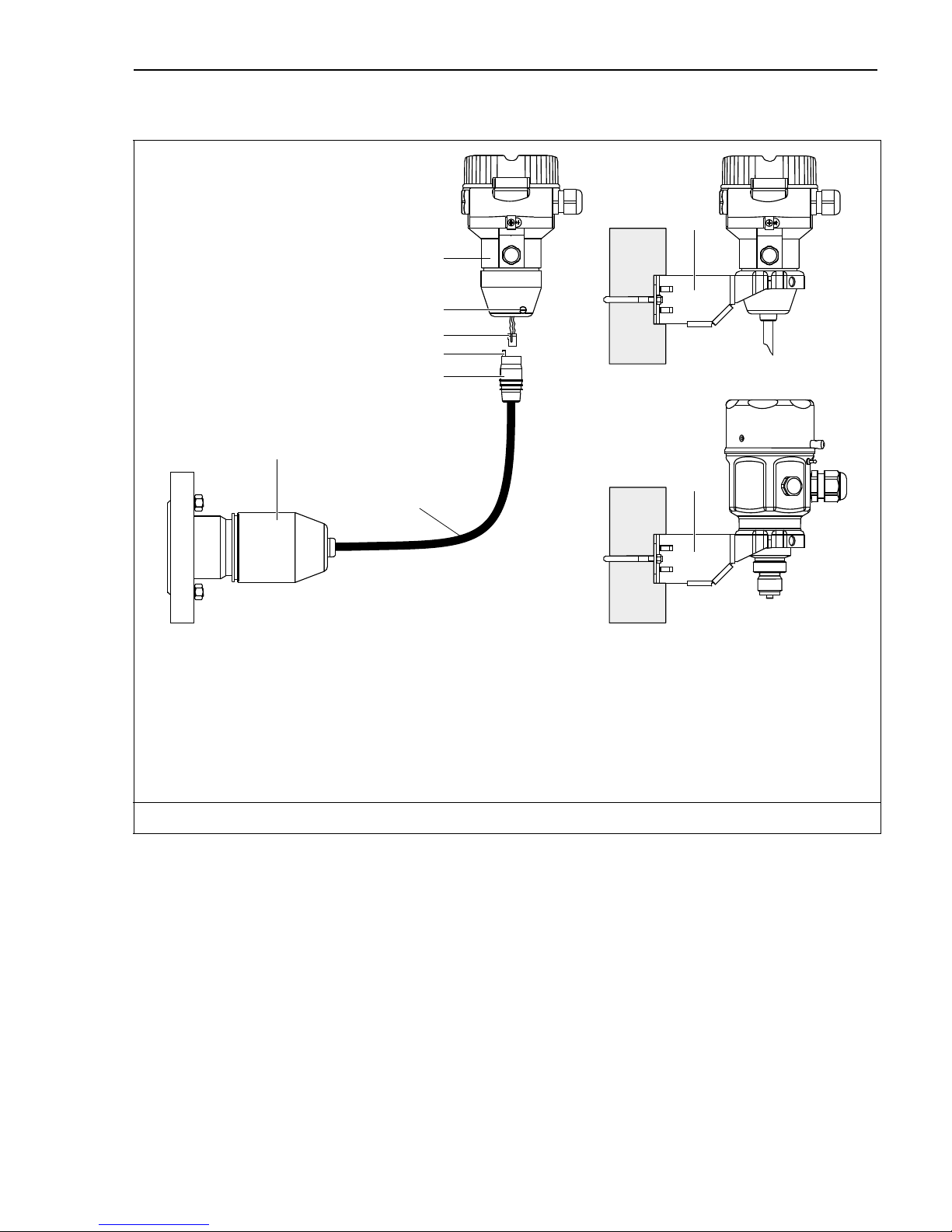
4.5.7 Assembling and mounting the "separate housing" version
Fig. 3: "Separate housing" version
1 In the case of the "separate housing" version, the sensor is delivered with the process connection and cable ready
mounted.
2 Cable with connection jack
3 Pressure compensation
4 Connector
5Locking screw
6 Housing mounted with housing adapter, included
7 Mounting bracket provided, suitable for pipe and wall mounting (for pipes from 1
Maßeinheit mm (in)
1/4
" up to 2" diameter)
Assembly and mounting
1. Insert the connector (item 4) into the corresponding connection jack of the cable (item 2).
2. Plug the cable into the housing adapter (item 6).
3. Tighten the locking screw (item 5).
4. Mount the housing on a wall or pipe using the mounting bracket (item 7).
When mounting on a pipe, tighten the nuts on the bracket uniformly with a torque of at
least 5 Nm (3.69 lbf ft). Mount the cable with a bending radius (r) 120 mm (4.72 in).
Routing the cable (e.g. through a pipe)
You require the cable shortening kit.
A0028494
Endress+Hauser 15
Page 16

Installation Deltapilot M FOUNDATION Fieldbus
NOTICE
NOTICE
Order number: 71093286
For details on mounting, see SD00553P/00/A6.
4.5.8 Supplementary installation instructions
Sealing the probe housing
• Moisture must not penetrate the housing when mounting the device, establishing the
electrical connection and during operation.
• Always firmly tighten the housing cover and the cable entries.
4.6 Mounting of the profile seal for universal process mounting
adapter
For details on mounting, see KA00096F/00/A3.
4.7 Closing the housing cover
Devices with EPDM cover seal - transmitter leakiness!
Mineral-based, animal-based or vegetable-based lubricants cause the EPDM cover seal to swell
and the transmitter to become leaky.
‣ The thread is coated at the factory and therefore does not require any lubrication.
The housing cover can no longer be closed.
Damaged thread!
‣ When closing the housing cover, please ensure that the thread of the cover and housing are
free from dirt, e.g. sand.If you feel any resistance when closing the cover, check the thread
on both again to ensure that they are free from dirt.
4.7.1 Closing the cover on the stainless steel housing
Fig. 4: Closing the cover
16 Endress+Hauser
A0028497
Page 17

Deltapilot M FOUNDATION Fieldbus Electrical connection
WARNING
!
The cover for the electronics compartment is tightened by hand at the housing until the stop.
The screw serves as DustEx protection (only available for devices with DustEx approval).
4.8 Post-installation check
O Is the device undamaged (visual inspection)?
O Does the device comply with the measuring point specifications?
For example:
•Process temperature
• Process pressure
• Ambient temperature range
•Measuring range
O Are the measuring point identification and labeling correct (visual inspection)?
O Is the device adequately protected against precipitation and direct sunlight?
O Are the securing screw and securing clamp tightened securely?
5 Electrical connection
5.1 Connecting the device
Supply voltage might be connected!
Risk of electric shock and/or explosion!
‣ Ensure that no uncontrolles processes are activated in the system.
‣ Switch off the supply voltage before connecting the device.
‣ When using the measuring device in hazardous areas, installation must comply with the
corresponding national standards and regulations and the Safety Instructions or Installation
or Control Drawings.
‣ A suitable circuit breaker must be provided for the device in accordance with
IEC/EN61010.
‣ Devices with integrated overvoltage protection must be grounded.
‣ Protective circuits against reverse polarity, HF influences and overvoltage peaks are
integrated.
Connect the device in the following order:
1. Check that the supply voltage corresponds to the supply voltage indicated on the nameplate.
2. Switch off the supply voltage before connecting the device.
3. Remove housing cover.
4. Guide the cable through the gland. Preferably use a twisted, shielded two-wire cable.
Endress+Hauser 17
Page 18

Electrical connection Deltapilot M FOUNDATION Fieldbus
- +
1
1
2
3
4
5. Connect the device in accordance with the following diagram.
6. Screw down the housing cover.
7. Switch on the supply voltage.
FOUNDATION Fieldbus electrical connection
1 Terminals for supply voltage and signal
2 Grounding terminal
3 Supply voltage: 9 to 32 VDC (Power conditioner)
4 External ground terminal
A0029967
18 Endress+Hauser
Page 19

Deltapilot M FOUNDATION Fieldbus Electrical connection
2
1
4
3
5.1.1 Devices with 7/8" plug
PIN assignment for 7/8" connector PIN Meaning
1 Signal –
2 Signal +
3 Not assigned
4Shield
A0011176
5.2 Connecting the measuring unit
5.2.1 Supply voltage
Electronic version
FOUNDATION Fieldbus,
version for non-hazardous areas
9 to 32 V DC
For further information on the network structure and grounding and for further bus system
components such as bus cables, see the relevant documentation, e.g. Operating Instructions
BA00013S "FOUNDATION Fieldbus Overview" and the FOUNDATION Fieldbus Guideline.
5.2.2 Current consumption
16 mA ±1 mA, switch-on current corresponds to IEC 61158-2, Clause 21.
5.2.3 Terminals
• Supply voltage and internal ground terminal: 0.5 to 2.5 mm2 (20 to 14 AWG)
2
• External ground terminal: 0.5 to 4 mm
(20 to 12 AWG)
5.2.4 Cable specification
• Endress+Hauser recommends using twisted, shielded two-wire cables.
• Cable outer diameter: 5 to 9 mm (0.2 to 0.35 in)
For further information on the cable specifications, see Operating Instructions BA00013S
"FOUNDATION Fieldbus Overview", FOUNDATION Fieldbus Guideline and IEC 61158-2 (MBP).
Endress+Hauser 19
Page 20

Operation Deltapilot M FOUNDATION Fieldbus
on
off
Display
Zero
simulation
TMTM
F
OUNDATIONFOUNDATION
SW / P2=High
SW / Ö
damping
delta p only
5.2.5 Shielding/potential equalization
• You achieve optimum shielding against disturbances if the shielding is connected on both
sides (in the cabinet and on the device). If potential equalization currents are expected in the
plant, only ground shielding on one side, preferably at the transmitter.
• When using in hazardous areas, you must observe the applicable regulations.
Separate Ex documentation with additional technical data and instructions is included with
all Ex systems as standard.
5.3 Potential equalization
Hazardous area applications: Connect all devices to the local potential equalization.
Observe the applicable regulations.
5.4 Overvoltage protection (optional)
See operating instructions.
5.5 Post-connection check
Perform the following checks after completing electrical installation of the device:
• Does the supply voltage match the specifications on the nameplate?
• Is the device properly connected?
• Are all screws firmly tightened?
• Are the housing covers screwed down tight?
As soon as voltage is applied to the device, the green LED on the electronic insert lights up briefly
or the connected onsite display lights up.
6Operation
6.1 Operating options
6.1.1 Operation without operating menu
Operating options Explanation Graphic illustration Description
Local operation without
device display
The device is operated
using the operating key
and DIP switches on the
electronic insert.
ä 22
20 Endress+Hauser
Page 21

Deltapilot M FOUNDATION Fieldbus Operation
E
+
–
6.1.2 Operation with an operating menu
Operation with an operating menu is based on an operation concept with "user roles" ä 24.
Operating options Explanation Graphic illustration Description
Local operation
with device display
Remote operation via
FieldCare
The device is operated
using the operating keys
on the device display.
The device is operated
using the FieldCare
operating tool.
ä 26
ä 30
6.1.3 Operation via FF communication protocol
Operating options Explanation Graphic illustration Description
Remote operation via
FieldCare
Remote operation via
the NI Tool
The device is operated
using the FieldCare
operating tool.
The device is operated
using the NI Tool.
See operating
instructions
See operating
instructions
Endress+Hauser 21
Page 22

Operation Deltapilot M FOUNDATION Fieldbus
on
off
SW / P2=High
Simulation
SW /
damping
1
2
345
on
off
Display
Zero
simulation
TM
F
OUNDATION
SW / P2=High
SW /
damping
delta p only
8 765 4
1
2
3
6.2 Operation without an operating menu
6.2.1 Position of operating elements
The operating key and DIP switches are located on the electronic insert in the device.
Fig. 5: FOUNDATION Fieldbus electronic insert
A0023127
1 Operating key for position zero adjustment (Zero) or reset
2 Green LED to indicate successful operation
3 Slot for optional local display
4+5 DIP switch only for Deltabar M
6 DIP-switch for simulation mode
7 DIP switch for switching damping on/off
8 DIP switch for locking/unlocking parameters relevant to the measured value
Function of the DIP switches
Switches Symbol/
Switch position
labeling
1 The device is unlocked.
Parameters relevant to the measured value
can be modified.
"off" "on"
The device is locked.
Parameters relevant to the measured value
cannot be modified.
22 Endress+Hauser
Page 23

Deltapilot M FOUNDATION Fieldbus Operation
Switches Symbol/
labeling
"off" "on"
2damping Damping is switched off.
The output signal follows measured value
changes without any delay.
3 Simulation The simulation mode is switched off
(factory setting).
The following switches only for Deltabar M:
4SW/
5 SW/P2= High
1) The value for the delay time can be configured via the operating menu ("Setup" -> "Damping").
Factory setting: = 2 s or as per order specifications.
Switch position
Damping is switched on.
The output signal follows measured value
changes with the delay time .
The simulation mode is switched on.
Function of the operating elements
Operating key Meaning
"Zero"
pressed for at least
3seconds
Position adjustment (zero point correction)
Press key for at least 3 seconds. The LED on the electronic insert lights up briefly if the
pressure applied has been accepted for position adjustment.
See also the following Section "Performing position adjustment on site.''
1)
"Zero"
pressed for at least
12 seconds
Reset
All parameters are reset to the order configuration.
Performing position adjustment on site
• Operation must be unlocked. ä 30, Section 6.3.5 "Locking/unlocking operation".
• The device is configured at the factory for the Level measuring mode.
– Operation via FF configuration program: In the Pressure Transducer Block, you can change
the measuring mode by means of the PRIMARY_VALUE_TYPE parameter.
• The pressure applied must be within the nominal pressure limits of the sensor. See
information on the nameplate.
• To reconcile the parameter database, perform a "Reconcile device" (after position adjustment)
with the FF host.
Perform position adjustment:
1. Pressure is present at device.
2. Press key for at least 3 seconds.
3. If the LED on the electronic insert lights up briefly, the pressure applied has been accepted
for position adjustment.
If the LED does not light up, the pressure applied was not accepted. Observe the input
limits. For error messages, see operating instructions.
Endress+Hauser 23
Page 24

Operation Deltapilot M FOUNDATION Fieldbus
6.2.2 Locking/unlocking operation
See operating instructions.
6.3 Operation with an operating menu
6.3.1 Operation concept
The operation concept makes a distinction between the following user roles:
User role Meaning
Operator Operators are responsible for the devices during normal "operation". This is usually limited to
reading process values either directly at the device or in a control room. If the work with the
devices extends beyond value read-off tasks, the tasks involve simple, application-specific
functions that are used in operation. Should an error occur, these users simple forward the
information on the errors but do not intervene themselves.
Service
engineer/technician
Expert Experts work with the devices over the entire product life cycle, but their device requirements
Service engineers usually work with the devices in the phases following device commissioning.
They are primarily involved in maintenance and troubleshooting activities for which simple
settings have to be made at the device.
Technicians work with the devices over the entire life cycle of the product.
Thus, commissioning and advanced settings and configurations are some of the tasks they have
to carry out.
are often extremely high. Individual parameters/functions from the overall functionality of the
devices are required for this purpose time and again.
In addition to technical, process-oriented tasks, experts can also perform administrative tasks
(e.g. user administration).
"Experts" can avail of the entire parameter set.
6.3.2 Structure of the operating menu
User role Submenu Meaning/use
Operator Language Only consists of the "Language" parameter (000) where the operating language
for the device is specified.
The language can always be changed even if the device is locked.
Operator Display/operat. Contains parameters that are needed to configure the measured value display
(selecting the values displayed, display format, display contrast, etc.).
With this submenu, users can change the measured value display without
affecting the actual measurement.
24 Endress+Hauser
Page 25

Deltapilot M FOUNDATION Fieldbus Operation
User role Submenu Meaning/use
Service
engineer/technic
ian
Service
engineer/technic
ian
Setup Contains all the parameters that are needed to commission measuring
operations. This submenu has the following structure:
• Standard setup parameters
A wide range of parameters, which can be used to configure a typical
application, is available at the start. The measuring mode selected determines
which parameters are available.
After making settings for all these parameters, the measuring operation
should be completely configured in the majority of cases.
• "Extended setup" submenu
The "Extended setup" submenu contains additional parameters for more
in-depth configuration of the measurement operation to convert the
measured value and to scale the output signal.
This menu is split into additional submenus depending on the measuring
mode selected.
Diagnosis Contains all the parameters that are needed to detect and analyze operating
errors. This submenu has the following structure:
• Diagnostic list
Contains up to 10 error messages currently pending.
• Event logbook
Contains the last 10 error messages (no longer pending).
• Instrument info
Contains information on the device identification.
• Measured values
Contains all the current measured values
• Simulation
Is used to simulate pressure, level and alarm/warning.
• Reset
Expert Expert Contains all the parameters of the device (including those in one of the
submenus). The "Expert" submenu is structured by the function blocks of the
device. It thus contains the following submenus:
• System
Contains general device parameters that neither affect measurement nor
integration into a distributed control system.
• Measurement
Contains all the parameters for configuring the measurement.
• Communication
Contains all the parameters of the FOUNDATION Fieldbus interface.
• Application
Contains all the parameters for configuring the functions that go beyond the
actual measurement (e.g. totalizer).
• Diagnosis
Contains all the parameters that are needed to detect and analyze operating
errors.
For an overview of the entire operating menu: See operating instructions.
Direct access to parameters
The parameters can only be accessed directly via the "Expert" user role.
Endress+Hauser 25
Page 26

Operation Deltapilot M FOUNDATION Fieldbus
1.
2.
3.
4.
5.
6.
Parameter name Description
Direct access (119)
Entry
Menu path:
Expert Direct access
Use this function to enter a parameter code for direct access.
User input:
• Enter the desired parameter code.
Factory setting:
0
6.3.3 Operation with a device display (optional)
A 4-line liquid crystal display (LCD) is used for display and operation. The onsite display shows
measured values, dialog texts, fault messages and notice messages.
For easy operation the display can be taken out of the housing (see figure steps 1 to 3). It is
connected to the device through a 90 mm (3.54 in) cable.
The display of the device can be turned in 90° stages (see figure steps 4 to 6).
Depending on the orientation of the device, this makes it easy to operate the device and read the
measured values.
26 Endress+Hauser
A0028500
Page 27

Deltapilot M FOUNDATION Fieldbus Operation
E
+
–
F
1
6
2
57
3
4
Functions:
• 8-digit measured value display including sign and decimal point.
• Bar graph as graphic display of the current pressure measured value in relation to the set
pressure range in the Pressure Transducer Block. The pressure range is set by means of the
SCALE_IN parameter (via FF configuration program, not via onsite display).
• Three keys for operation.
• Simple and complete menu guidance as parameters are split into several levels and groups.
• Each parameter is given a 3-digit parameter code for easy navigation.
• Possibility of configuring the display to suit individual requirements and preferences, such as
language, alternating display, display of other measured values such as sensor temperature,
contrast setting.
• Comprehensive diagnostic functions (fault and warning message etc.).
Fig. 6: Display
1 Main line
2Value
3Symbol
4Unit
5Bar graph
6 Information line
7Operating keys
A0030013
The following table illustrates the symbols that can appear on the onsite display. Four symbols
can occur at one time.
Symbol Meaning
Lock symbol
The operation of the device is locked. To unlock the device, ä 30, Locking/unlocking
operation.
Endress+Hauser 27
Page 28

Operation Deltapilot M FOUNDATION Fieldbus
Symbol Meaning
Communication symbol
Data transfer via communication
Error message "Out of specification"
The device is being operated outside its technical specifications (e.g. during warmup or
cleaning processes).
Error message "Service mode"
The device is in the service mode (during a simulation, for example).
Error message "Maintenance required"
Maintenance is required. The measured value remains valid.
Error message "Failure detected"
An operating error has occurred. The measured value is no longer valid.
Simulation symbol
Simulation mode is activated. DIP switch 2 for simulation is set to "On".
See also Section 6.2.1 "Position of operating elements" and ä 30, Section 6.3.6
"Simulation".
Operating keys on the display and operating module
Operating key(s) Meaning
– Navigate downwards in the picklist
– Edit the numerical values and characters within a function
– Navigate upwards in the picklist
– Edit the numerical values and characters within a function
–Confirm entry
– Jump to the next item
– Selection of a menu item and activation of the editing mode
Contrast setting of onsite display: darker
Contrast setting of onsite display: brighter
O
S
O
S
F
and
and
F
F
ESC functions:
and
O
28 Endress+Hauser
S
– Exit the edit mode for a parameter without saving the changed value.
– You are in a menu at a selection level. Each time you press the keys simultaneously,
you go up a level in the menu.
Page 29

Deltapilot M FOUNDATION Fieldbus Operation
Operating example: Parameters with a picklist
Example: selecting "Deutsch" as the language of the menu.
Language 000 Operation
1 English "English" is set as the menu language (default value). A in front
of the menu text indicates the active option.
Deutsch
2 Deutsch Select "Deutsch" with or .
English
3 Deutsch 1. Confirm your choice with . A in front of the menu text
indicates the active option ("Deutsch" is now selected as the
English
menu language).
2. Exit the edit mode for the parameter with .
Operating example: User-definable parameters
Example: setting "Set URV" parameter from 100 mbar (1.5 psi) to 50 mbar (0.75 psi).
Set URV 014 Operation
The local display shows the parameter to be changed. The value
1100.000mbar
2 1 00 . 000 mbar
3 5 00 . 000 mbar
4500 .000 mbar
highlighted in black can be changed. The "mbar" unit is specified
in another parameter and cannot be modified here.
1. Press or to get to the editing mode.
2. The first digit is highlighted in black.
1. Use to change "1" to "5".
2. Confirm "5" with . The cursor jumps to the next position
(highlighted in black).
3. Confirm "0" with (second position).
The third position is highlighted in black and can now be edited.
550 .000 mbar
Endress+Hauser 29
1. Switch to the "" symbol with the key.
2. Use to save the new value and exit the editing mode.
See next graphic.
Page 30

Operation Deltapilot M FOUNDATION Fieldbus
Set URV 014 Operation
The new value for the upper range value is 50.0 mbar (0.75 psi).
65 .000 mbar
– You exit the edit mode for the parameter with .
– You can get back to the editing mode with or .
Operating example: Accepting the pressure present
Example: setting position adjustment
Pos. zero adjust 007 Operation
1 Abort The pressure for position adjustment is present at the device.
Confirm
2 Confirm Use or to switch to the "Confirm" option. The active option is
highlighted in black.
Abort
3Compensation
accepted!
4 Abort Exit the edit mode for the parameter with .
Confirm
Accept the pressure present as position adjustment with the
key. The device confirms the adjustment and goes back to the
"Pos. zero adjust" parameter.
6.3.4 Operation via FieldCare
See operating instructions.
6.3.5 Locking/unlocking operation
See operating instructions.
6.3.6 Simulation
See operating instructions.
6.3.7 Resetting to factory settings (reset)
See operating instructions.
30 Endress+Hauser
Page 31

Deltapilot M FOUNDATION Fieldbus Commissioning without an operating menu
WARNING
!
6.4 FOUNDATION Fieldbus communication protocol
6.4.1 Device identification and addressing
FOUNDATION Fieldbus identifies the device using its ID code and automatically assigns it a
suitable field address. The identity code cannot be changed.
The device appears in the network display once you have started the FF configuration program
and integrated the device into the network. The blocks available are displayed under the device
name.
If the device description has not yet been loaded, the blocks report "Unknown" or "(UNK)".
The devices report as follows (typical display in a configuration program after the connection
has been established):
Device name Serial number
-
-
EH_ Deltapilot_M_5X _ 00000000000000
RS_00000000000 (RB2)
TRD1_00000000000 (PCD)
DIAGNOSTIC_000000000000 (DIAGNOSTIC)
DISPLAY_00000000000 (DISP)
AI1_000000000000 (AI)
AI2_000000000000 (AI)
DI_00000000000 (DI)
DO_00000000000 (DO)
ISEL_00000000000(ISB)
PID_00000000000(PID)
ARTH_00000000000(ARB)
CHAR_00000000000(SCB)
INTG_0000000000 (ITB)
7 Commissioning without an operating menu
The device is configured at the factory for the Level measuring mode. The measuring range and
the unit in which the measured value is transmitted correspond to the specifications on the
nameplate.
Exceeding the maximum allowable working pressure!
Risk of injury due to bursting of parts! Warning messages are generated if pressure is too high.
‣ If a pressure smaller than the minimum permitted pressure or greater than the maximum
permitted pressure is present at the device, the following messages are output in succession
(depending on the setting in the "Alarm behavior" (050) parameter):
"S140 Working range P" or "F140 Working range P"
Endress+Hauser 31
Page 32

Commissioning without an operating menu Deltapilot M FOUNDATION Fieldbus
NOTICE
"S841 Sensor range" or "F841 Sensor range"
"S971 Adjustment"
Use the device only within the sensor range limits.
Shortfall of the allowable working pressure!
Output of messages if pressure is too low.
‣ If a pressure smaller than the minimum permitted pressure or greater than the maximum
permitted pressure is present at the device, the following messages are output in succession
(depending on the setting in the "Alarm behavior" (050) parameter):
"S140 Working range P" or "F140 Working range P"
"S841 Sensor range" or "F841 Sensor range"
"S971 Adjustment"
Use the device only within the sensor range limits.
7.1 Function check
Carry out a post-installation and a post-connection check as per the checklist before
commissioning the device.
• "Post-installation check" checklist ä 17
• "Post-connection check" checklist ä 20
7.2 Position adjustment
The following functions are possible by means of the key on the electronic insert:
• Position adjustment (zero point correction)
• Device reset ä 23
• Operation must be unlocked. ä 30, "Locking/unlocking operation"
• The device is configured for the "Pressure" measuring mode as standard.
• The pressure applied must be within the nominal pressure limits of the sensor. See
information on the nameplate.
Carrying out position adjustment
Pressure is present at device.
1)
Does the LED on the electronic insert light up briefly?
Yes No
32 Endress+Hauser
Press the "Zero" key for at least 3 s.
Page 33

Deltapilot M FOUNDATION Fieldbus Commissioning with an operating menu (onsite display/FieldCare)
WARNING
!
NOTICE
Carrying out position adjustment
Applied pressure for position adjustment has been
accepted.
1) Observe warning on commissioning
Applied pressure for position adjustment has not been
1)
accepted. Observe the input limits.
8 Commissioning with an operating menu (onsite
display/FieldCare)
The device is configured at the factory for the Level measuring mode. The measuring range and
the unit in which the measured value is transmitted correspond to the specifications on the
nameplate.
Exceeding the maximum allowable working pressure!
Risk of injury due to bursting of parts! Warning messages are generated if pressure is too high.
‣ If a pressure smaller than the minimum permitted pressure or greater than the maximum
permitted pressure is present at the device, the following messages are output in succession
(depending on the setting in the "Alarm behavior" (050) parameter):
"S140 Working range P" or "F140 Working range P"
"S841 Sensor range" or "F841 Sensor range"
"S971 Adjustment"
Use the device only within the sensor range limits.
Shortfall of the allowable working pressure!
Output of messages if pressure is too low.
‣ If a pressure smaller than the minimum permitted pressure or greater than the maximum
permitted pressure is present at the device, the following messages are output in succession
(depending on the setting in the "Alarm behavior" (050) parameter):
"S140 Working range P" or "F140 Working range P"
"S841 Sensor range" or "F841 Sensor range"
"S971 Adjustment"
Use the device only within the sensor range limits.
8.1 Function check
Carry out a post-installation and a post-connection check as per the checklist before
commissioning the device.
• "Post-installation check" checklist ä 17
• "Post-connection check" checklist ä 20
Endress+Hauser 33
Page 34

Commissioning with an operating menu (onsite display/FieldCare) Deltapilot M FOUNDATION Fieldbus
WARNING
!
8.2 Commissioning
Commissioning comprises the following steps:
1. Function check ( ä 33)
2. Selecting the language, measuring mode and pressure unit ( ä 34)
3. Position adjustment ( ä 35)
4. Configuring measurement:
– Pressure measurement ( ä 46 ff)
– Level measurement ( ä 36 ff)
–Linearization ( ä 46 ff)
8.2.1 Selecting the language, measuring mode and pressure unit
Language selection
Parameter name Description
Language (000)
Options
Menu path:
Main menu Language
Select the menu language for the onsite display.
Options:
• English
• Possibly another language (as selected when ordering the device)
• One further language (language of the manufacturing plant)
Factory setting:
English
Measuring mode selection
Parameter name Description
Measuring mode (005)
Options
Menu path: Setup
Measuring mode
Select the measuring mode.
The operating menu is structured differently depending on the measuring mode
selected.
Changing the measuring mode affects the span (URV)!
This situation can result in product overflow.
‣ If the measuring mode is changed, the span setting (URV) must be verified and, if
necessary, reconfigured!
Options:
• Pressure
• Level
Factory setting:
Pressure
34 Endress+Hauser
Page 35

Deltapilot M FOUNDATION Fieldbus Commissioning with an operating menu (onsite display/FieldCare)
Pressure unit selection
Parameter name Description
Press. eng. unit (125)
Options
Menu path: Setup Press.
eng. unit
Select the pressure unit.
If a new pressure unit is selected, all pressure-specific parameters are converted and
displayed with the new unit.
Options:
• mbar, bar
• mmH2O, mH2O,
•inH2O, ftH2O
•Pa, kPa, MPa
•psi
• mmHg, inHg
•kgf/cm
Factory setting:
mbar or bar depending on the sensor nominal measuring range, or as per order
specifications
2
8.3 Pos. zero adjust
The pressure resulting from the orientation of the device can be corrected here.
Parameter name Description
Corrected press. (172)
Display
Menu path:
Setup Corrected press.
Displays the measured pressure after sensor trim and position adjustment.
If this value is not equal to "0", it can be corrected to "0" by the position adjustment.
Pos. zero adjust (007)
(Gauge pressure sensor)
Selection
Menu path:
Setup Pos. zero adjust
Position adjustment – the pressure difference between zero (set point) and the
measured pressure need not be known.
Example:
– Measured value = 2.2 mbar (0.032 psi)
– You correct the measured value via the "Pos. zero adjust" parameter with the
"Confirm" option. This means that you are assigning the value 0.0 to the pressure
present.
– Measured value (after pos. zero adjust) = 0.0 mbar
Options
•Confirm
•Abort
Factory setting:
Abort
Endress+Hauser 35
Page 36

Commissioning with an operating menu (onsite display/FieldCare) Deltapilot M FOUNDATION Fieldbus
Parameter name Description
Calib. offset (192) / (008)
(absolute pressure sensor)
Entry
Menu path:
Setup Calib. offset
Position adjustment – the pressure difference between the set point and the measured
pressure must be known.
Example:
– Measured value = 982.2 mbar (14.24 psi)
– You correct the measured value with the value entered (e.g. 2.2 mbar (0.032 psi))
via the "Calib. offset" parameter. This means that you are assigning the value 980.0
(14.21 psi) to the pressure present.
– Measured value (after calib. offset) = 980.0 mbar (14.21 psi)
Factory setting:
0.0
8.4 Level measurement
8.4.1 Information on level measurement
• The limit values are not checked, i.e. the values entered must be appropriate for the sensor
and the measuring task for the device to be able to measure correctly.
• Customer-specific units are not possible.
• There is no unit conversion.
• The values entered for "Empty calib. (028)/Full calib. (031)", "Empty pressure (029)/Full
pressure (032)", "Empty height (030)/Full height (033)" must be at least 1 % apart. The value
will be rejected, and a warning message displayed, if the values are too close together.
You have a choice of two methods for calculating the level: "In pressure" and "In height". The table
in the "Overview of level measurement" section that follows provides you with an overview of
these two measuring tasks.
8.4.2 Overview of level measurement
Measuring task Level
selection
Calibration is
performed by entering
two pressure-level
value pairs.
Calibration is
performed by entering
the density and two
height-level value
pairs.
"In pressure" Via the "Unit before
"In height" – Calibration with reference
Measured
variable options
lin. (025)"
parameter: %, level,
volume or mass
units.
Description Measured value display
– Calibration with reference
pressure (wet calibration),
see ä 37
– Calibration without
reference pressure (dry
calibration), see ä 39
pressure (wet calibration),
see ä 44
– Calibration without
reference pressure (dry
calibration), see ä 41
The measured value
display and the
"Level before lin. (019)"
parameter display the
measured value.
36 Endress+Hauser
Page 37

Deltapilot M FOUNDATION Fieldbus Commissioning with an operating menu (onsite display/FieldCare)
B
300 mbar
3 m
A
0 mbar
0 m
8.4.3 "In pressure" level selection
Calibration with reference pressure (wet calibration)
Example:
In this example, the level in a tank should be measured in "m". The maximum level is 3 m (9.8
ft). The pressure range is due to the filling height and the density.
Prerequisite:
• The measured variable is in direct proportion to the pressure.
• The tank can be filled and emptied.
The values entered for "Empty calib. (028)/Full calib. (031)" and the pressures present at the
device must be at least 1% apart. The value will be rejected, and a warning message displayed,
if the values are too close together. Further limit values are not checked; i.e. the values entered
must be appropriate for the sensor and the measuring task so that the measuring device can
measure correctly.
Description
1 Perform "position adjustment" ä 35.
2 Select the "Level" measuring mode via the
"Measuring mode (005)" parameter.
Menu path: Setup Measuring mode (005)
3 Select a pressure unit by means of the "Press. eng.
unit (125)" parameter, here "mbar" for example.
Menu path: Setup Press. eng. unit (125)
4 Select the "In pressure" level mode by means of the
"Level selection (024)" parameter.
Menu path: Setup Extended Setup Level
Level selection (024)
Fig. 7: Calibration with reference pressure –
A0030028
wet calibration
A See Table, Step 7.
B See Table, Step 8.
Endress+Hauser 37
Page 38

Commissioning with an operating menu (onsite display/FieldCare) Deltapilot M FOUNDATION Fieldbus
A
B
h
[m]
p
[mbar]
3
0
0 300
Description
5 Select a level unit by means of the "Unit before lin.
(025)" parameter, here "m" for example.
Menu path: Setup Extended Setup Level
Unit before lin. (025)
6 Select the "Wet" option by means of the "Calibration
mode (027)" parameter.
Menu path: Setup Extended Setup Level
Calibration mode (027)
7 The pressure for the lower calibration point is
present at the device, here 0 mbar for example.
Select the "Empty calib. (028)" parameter.
Menu path: Setup Extended Setup Level
Empty calib. (028)
Enter the level value, here 0 m for example. The
pressure value present is assigned to the lower level
value by confirming the value.
8 The pressure for the upper calibration point is
present at the device, here 300 mbar (4.35 psi) for
example.
Select the "Full calib. (031)" parameter.
Menu path: Setup Extended Setup Level
Full calib. (031)
Enter the level value, here 3 m (9.8 ft) for example.
The pressure value present is assigned to the upper
level value by confirming the value.
9 If calibration is performed with a medium other
than the process medium, enter the density of the
calibration medium in "Adjust density (034)".
Menu path: Setup Extended Setup Level
Adjust density (034)
10 If calibration was performed with a medium other
than the process medium, specify the density of the
process medium in the "Process density (035)"
parameter.
Menu path: Setup Extended Setup Level
Process density (035)
11 Result:
The measuring range is set for 0 to 3 m (9.8 ft).
Fig. 8: Calibration with reference pressure –
A0017658
wet calibration
C See Table, Step 7.
D See Table, Step 8.
The measured variables %, level, volume and mass are available for this level mode.
See operating instructions "Unit before lin. (025)".
38 Endress+Hauser
Page 39

Deltapilot M FOUNDATION Fieldbus Commissioning with an operating menu (onsite display/FieldCare)
B
1000 l
450 mbar
A
0 l
50 mbar
r=1
g
cm
3
8.4.4 "In pressure" level selection
Calibration without reference pressure (dry calibration)
Example:
In this example, the volume in a tank should be measured in liters. The maximum volume of
1000 liters (264 gal) corresponds to a pressure of 450 mbar (6.53 psi). The minimum volume
of 0 liters corresponds to a pressure of 50 mbar (0.72 psi) since the device is mounted below the
start of the level measuring range.
Prerequisite:
• The measured variable is in direct proportion to the pressure.
• This is a theoretical calibration i.e. the pressure and volume values for the lower and upper
calibration point must be known.
• The values entered for "Empty calib. (028)/Full calib. (031)", "Empty pressure (029)/Full
pressure (032)" must be at least 1% apart. The value will be rejected, and a warning message
displayed, if the values are too close together. Further limit values are not checked; i.e. the
values entered must be appropriate for the sensor and the measuring task so that the
measuring device can measure correctly.
• Due to the orientation of the device, there may be pressure shifts in the measured value, i.e.
when the container is empty or partly filled, the measured value is not zero. For information
on how to perform position adjustment, see ä 35, "Pos. zero adjust".
Description
1 Select the "Level" measuring mode via the
"Measuring mode (005)" parameter.
Menu path: Setup Measuring mode (005)
2 Select a pressure unit by means of the "Press. eng.
unit (125)" parameter, here "mbar" for example.
Menu path: Setup Press. eng. unit (125)
3 Select the "In pressure" level mode by means of the
"Level selection (024)" parameter.
Menu path: Setup Extended Setup Level
Level selection (024)
4 Select a volume unit by means of the "Unit before
lin. (025)" parameter, here "l" (liter) for example.
Menu path: Setup Extended Setup Level
Unit before lin. (025)
Fig. 9: Calibration without reference pressure –
A0030030
dry calibration
A See Table, Step 7.
C See Table, Step 8.
B See Table, Step 9.
D See Table, Step 10.
Endress+Hauser 39
Page 40

Commissioning with an operating menu (onsite display/FieldCare) Deltapilot M FOUNDATION Fieldbus
A
B
C
D
V
[l]
p
[mbar]
1000
0
50450
Description
5 Select the "Dry" option by means of the "Calibration
mode (027)" parameter.
Menu path: Setup Extended Setup Level
Calibration mode (027)
6 "Adjust density (034)" contains the factory setting
1.0, but this value can be changed if required. The
entered value pairs must correspond to this density.
Menu path: Setup Extended Setup Level
Adjust density (034)
7 Enter the volume value for the lower calibration
point via the "Empty calib. (028)" parameter, here 0
liters for example.
Menu path: Setup Extended Setup Level
Empty calib. (028)
8 Enter the pressure value for the lower calibration
point via the "Empty pressure (029)" parameter,
here 50 mbar (0.72 psi) for example.
Menu path: Setup Extended Setup Level
Empty pressure (029)
9 Enter the volume value for the upper calibration
point via the "Full calib. (031)" parameter, here
1000 liters (264 gal) for example.
Menu path: Setup Extended Setup Level
Full calib. (031)
10 Enter the pressure value for the upper calibration
point via the "Full pressure (032)" parameter, here
450 mbar (6.53 psi) for example.
Menu path: Setup Extended Setup Level
Full pressure (032)
11 If calibration was performed with a medium other
than the process medium, specify the density of the
process medium in the "Process density (035)"
parameter.
Menu path: Setup Extended Setup Level
Process density (035)
Fig. 10: Calibration with reference pressure –
A0031028
wet calibration
E See Table, Step 7.
F See Table, Step 8.
G See Table, Step 9.
H See Table, Step 10.
12 Result:
The measuring range is set for 0 to 1000 l (264
gal).
The measured variables %, level, volume and mass are available for this level mode.
See operating instructions "Unit before lin. (025)".
40 Endress+Hauser
Page 41

Deltapilot M FOUNDATION Fieldbus Commissioning with an operating menu (onsite display/FieldCare)
8.4.5 "In height" level selection
Calibration without reference pressure (dry calibration)
Example:
In this example, the volume in a tank should be measured in liters. The maximum volume of
1000 liters (264 gal) corresponds to a level of 4.5 m (14.8 ft). The minimum volume of 0 liters
corresponds to a level of 0.5 m (1.6 ft) since the device is mounted below the start of the level
measuring range.
Prerequisite:
• The measured variable is in direct proportion to the pressure.
• This is a theoretical calibration i.e. the height and volume values for the lower and upper
calibration point must be known.
• The values entered for "Empty calib. (028)/Full calib. (031)", "Empty height (030)/Full height
(033)" must be at least 1% apart. The value will be rejected, and a warning message displayed,
if the values are too close together. Further limit values are not checked; i.e. the values
entered must be appropriate for the sensor and the measuring task so that the measuring
device can measure correctly.
• Due to the orientation of the device, there may be pressure shifts in the measured value, i.e.
when the container is empty or partly filled, the measured value is not zero. For information
on how to perform position adjustment, see ä 35, "Pos. zero adjust".
Endress+Hauser 41
Page 42

Commissioning with an operating menu (onsite display/FieldCare) Deltapilot M FOUNDATION Fieldbus
C
1000 l
4.5 m
B
0 l
0.5 m
r=1
g
cm
3
A
Description
1 Select the "Level" measuring mode via the
"Measuring mode (005)" parameter.
Menu path: Setup Measuring mode (005)
2 Select a pressure unit via the "Press. eng. unit (125)"
parameter, here "mbar" for example.
Menu path: Setup Press. eng. unit (125)
3 Select the "In height" level mode via the "Level
selection (024)" parameter.
Menu path: Setup Extended Setup Level
Level selection (024)
4 Select a volume unit via the "Unit before lin. (025)"
parameter, here "l" (liter) for example.
Menu path: Setup Extended Setup Level
Unit before lin. (025)
5 Select a level unit by means of the "Height unit
(026)" parameter, here "m" for example.
Menu path: Setup Extended Setup Level
Height unit (026)
6 Select the "Dry" option by means of the "Calibration
mode (027)" parameter.
Menu path: Setup Extended Setup Level
Calibration mode (027)
Fig. 11: Calibration without reference pressure –
dry calibration
A See Table, Step 7.
B See Table, Steps 8 and 9.
C See Table, Steps 10 and 11..
A0031027
7 Enter the density of the medium via the "Adjust
density (034)" parameter, here "1 g/cm
example.
Menu path: Setup Extended Setup Level
Adjust density (034)
3
" (1 SGU) for
42 Endress+Hauser
Page 43

Deltapilot M FOUNDATION Fieldbus Commissioning with an operating menu (onsite display/FieldCare)
A
h
p
g=×r
h
p
g=×r
r=1
g
cm
3
B
D
CE
V
[l]
h
[m]
h
[m]
p
[mbar]
1000
4.5
0
0.5
0.5
50
4.5
450
Description
8 Enter the volume value for the lower calibration
point via the "Empty calib. (028)" parameter, here 0
liters for example.
Menu path: Setup Extended Setup Level
Empty calib. (028)
9 Enter the height value for the lower calibration
point via the "Empty height (030)" parameter, here
0.5 m (1.6 ft) for example.
Menu path: Setup Extended Setup Level
Empty height (030)
10 Enter the volume value for the upper calibration
point via the "Full calib. (031)" parameter, here
1000 liters (264 gal) for example.
Menu path: Setup Extended Setup Level
Full calib. (031)
11 Enter the height value for the upper calibration
point via the "Full height (033)" parameter, here 4.5
m (14.8 ft) for example.
Menu path: Setup Extended Setup Level
Full height (033)
12 If the process uses a medium other than that on
which the calibration was based, the new density
must be specified in the "Process density (035)"
parameter.
Menu path: Setup Extended Setup Level
Process density (035)
13 Result:
The measuring range is set for 0 to 1000 l (264
gal).
Fig. 12: Calibration with reference pressure –
A0031066
wet calibration
A See Table, Step 7.
B See Table, Step 8.
C See Table, Step 9.
D See Table, Step 10.
E See Table, Step 11.
The measured variables %, level, volume and mass are available for this level mode operating
instructions "Unit before lin. (025)".
Endress+Hauser 43
Page 44

Commissioning with an operating menu (onsite display/FieldCare) Deltapilot M FOUNDATION Fieldbus
C
1000 l
4.5 m
B
0 l
0.5 m
r=1
g
cm
3
A
8.4.6 "In height" level selection
Calibration with reference pressure (wet calibration)
Example:
In this example, the volume in a tank should be measured in liters. The maximum volume of
1000 liters (264 gal) corresponds to a level of 4.5 m (14.8 ft). The minimum volume of 0 liters
corresponds to a level of 0.5 m (1.6 ft) since the device is mounted below the start of the level
measuring range.
3
The density of the medium is 1 g/cm
(1 SGU).
Prerequisite:
• The measured variable is in direct proportion to the pressure.
• The tank can be filled and emptied.
The values entered for "Empty calib. (028)/Full calib. (031)" and the pressure values present at
the device must be at least 1% apart. The value will be rejected, and a warning message
displayed, if the values are too close together. Further limit values are not checked; i.e. the
values entered must be appropriate for the sensor and the measuring task so that the measuring
device can measure correctly.
Description
1 Perform position adjustment. See ä 35.
2 Select the "In height" level mode via the "Level
selection (024)" parameter.
Menu path: Setup Extended Setup Level
Level selection (024)
3 Select the "Level" measuring mode via the
"Measuring mode (005)" parameter.
Menu path: Setup Measuring mode (005)
4 Select a pressure unit via the "Press. eng. unit (125)"
parameter, here "mbar" for example.
Menu path: Setup Press. eng. unit (125)
5 Select a volume unit via the "Unit before lin. (025)"
parameter, here "l" (liter) for example.
Menu path: Setup Extended Setup Level
Unit before lin. (025)
Fig. 13: Calibration with reference pressure –
A0031027
wet calibration
A See Table, Step 8.
B See Table, Step 9.
C See Table, Step 10.
44 Endress+Hauser
Page 45

Deltapilot M FOUNDATION Fieldbus Commissioning with an operating menu (onsite display/FieldCare)
A
h
p
g=×r
h
p
g=×r
r=1
g
cm
3
B
C
V
[l]
h
[m]
h
[m]
p
[mbar]
1000
4.5
0
0.5
0.5
50
4.5
450
Description
6 Select a level unit by means of the "Height unit
(026)" parameter, here "m" for example.
Menu path: Setup Extended Setup Level
Height unit (026)
7 Select the "Wet" option by means of the "Calibration
mode (027)" parameter.
Menu path: Setup Extended Setup Level
Calibration mode (027)
8 If calibration is performed with a medium other
than the process medium, enter the density of the
calibration medium in the "Adjust density (034)"
parameter, here 1 g/cm
Menu path: Setup Extended Setup Level
Adjust density (034)
9 The pressure for the lower calibration point is
present at the device, here 0.5 m covered / 49 mbar
(0.71 psi) for example.
Enter the volume value for the lower calibration
point via the "Empty calib. (028)" parameter, here 0
liters for example. (The pressure currently
measured is displayed as the height, here 0.5 m
(1.6 ft) for example.)
Menu path: Setup Extended Setup Level
Empty calib. (028)
3
(1 SGU) for example.
10 The pressure for the upper calibration point is
present at the device, here 4.5 m covered / 441
mbar (6.4 psi) for example.
Enter the volume value for the upper calibration
point via the "Full calib. (031)" parameter, here
"1000 liters" (264 gal) for example. The pressure
currently measured is displayed as the height, here
"4.5 m" (14.8 ft) for example.
Menu path: Setup Extended Setup Level
Full calib. (031)
11 If calibration was performed with a medium other
than the process medium, specify the density of the
process medium in the "Process density (035)"
parameter.
Menu path: Setup Extended Setup Level
Process density (035)
12 Result:
The measuring range is set for 0 to 1000 l (264
gal).
Abb. 14: Abgleich mit Referenzdruck –
A0031029
Nassabgleich
A Siehe Tabelle, Schritt 8.
B Siehe Tabelle, Schritt 9.
C Siehe Tabelle, Schritt 10.
The measured variables %, level, volume and mass are available for this level mode operating
instructions "Unit before lin. (025)".
Endress+Hauser 45
Page 46

Commissioning with an operating menu (onsite display/FieldCare) Deltapilot M FOUNDATION Fieldbus
8.4.7 Required parameters for Level measuring mode
Parameter name Description
Level selection (024) See operating instructions
Unit before lin. (025) See operating instructions
Height unit (026) See operating instructions
Calibration mode (027) See operating instructions
Empty calib. (028) See operating instructions
Empty pressure (029) See operating instructions
Empty height (030) See operating instructions
Full calib. (031) See operating instructions
Full pressure (032) See operating instructions
Full height (033) See operating instructions
Density unit (127) See operating instructions
Adjust density (034) See operating instructions
Process density (035) See operating instructions
Level before lin. (019) See operating instructions
8.5 Linearization
See operating instructions.
8.6 Pressure measurement
8.6.1 Calibration without reference pressure (dry calibration)
Calibration is possible only using FieldCare.
Example:
In this example, a device with a 400 mbar (6 psi) sensor is configured for the 0 to +300 mbar
(4.35 psi) measuring range, i.e. 0 mbar and 300 mbar (4.35 psi) are assigned.
Prerequisite:
This is a theoretical calibration, i.e. the pressure values for the lower and upper range are
known.
46 Endress+Hauser
Page 47

Deltapilot M FOUNDATION Fieldbus Commissioning with an operating menu (onsite display/FieldCare)
Due to the orientation of the device, there may be pressure shifts in the measured value, i.e. the
measured value is not zero in a pressureless condition. For information on how to perform
position adjustment, see ä 35.
Description
1 Select the "Pressure" measuring mode via the "Measuring mode (005)" parameter.
Menu path: Setup Measuring mode (005)
2 Select a pressure unit via the "Scale in. Press. eng. unit" element, here "mbar" for example.
Menu path: Setup Scale in. Press. eng. unit
3 Enter a pressure value of 0 mbar via the "Scale in. Set LRV" element.
Menu path: Expert Communication Pressure Transducer Block Scale in. Set LRV
4 Enter a pressure value of 300 mbar (4.35 psi) via the "Scale in. Set LRV" element.
Menu path: Expert Communication Pressure Transducer Block Scale in. Set LRV
5Result:
The measuring range is configured for 0 to +300 mbar (4.35 psi).
8.6.2 Required parameters for Pressure measuring mode
Parameter name Description
Measuring mode (005) See operating instructions
Switch P1/P2 (163) See operating instructions
Press. eng. unit (125) See operating instructions
Corrected press. (172) See operating instructions
Pos. zero adjust (007) (Gauge pressure sensor) See operating instructions
Damping switch (164) See operating instructions
Damping value (017) See operating instructions
Pressure af. damp (111) See operating instructions
Endress+Hauser 47
Page 48

www.addresses.endress.com
71316893
 Loading...