

Page 1

TI00368C/07/EN/14.20
71478863
2020-04-30
Products
Solutions Services
Technical Information
Cleanfit COA451
Manually operated retractable assembly for water,
wastewater and process media
Application
Cleanfit COA451 is a retractable assembly for oxygen sensors with a diameter of 40
mm in:
• Wastewater treatment plants:
• Oxygen control in activated sludge basins
• Treatment and monitoring of process water
• Water works:
• Status monitoring for drinking water
• Water quality monitoring in rivers, lakes or seas
• All industrial utilities:
• Oxygen control in biological treatment
• Treatment and monitoring of process water
• Fish farming:
Oxygen monitoring for optimum growth conditions
Your benefits
• One assembly for all applications: the 'one-for-all' principle optimizes inventory
management, accelerates project handling and simplifies life cycle management.
• Easy and safe maintenance: sensor servicing and cleaning without interrupting the
process.
• Robust design: process pressure up to 10 bar (145 psi), manual operation up to
2 bar (29 psi).
• Convenient, time-saving operation: rinse water connection enables cleaning
without having to remove the sensor from the process.
Page 2

Table of contents
Function and system design ................... 3
Structure of the assembly ........................ 3
Structure of the sensor holder ..................... 3
Measuring system ............................. 5
Installation ................................ 5
Orientation ................................. 5
Installation instructions ......................... 5
Environment ............................... 6
Ambient temperature .......................... 6
Process ................................... 6
Medium temperature ........................... 6
Medium pressure ............................. 6
Pressure-temperature ratings ..................... 6
Cleanfit COA451
Mechanical construction ...................... 7
Dimensions ................................. 7
Certificates and approvals ................... 11
CE/PED ................................... 11
Ordering information ....................... 11
Product page ............................... 11
Product Configurator .......................... 11
Scope of delivery ............................. 12
Accessories ............................... 12
Device-specific accessories ...................... 12
Service-specific accessories ...................... 14
Accessory kits ............................... 14
2
Page 3
Cleanfit COA451
1
2
3
4
5
6
8
9
7
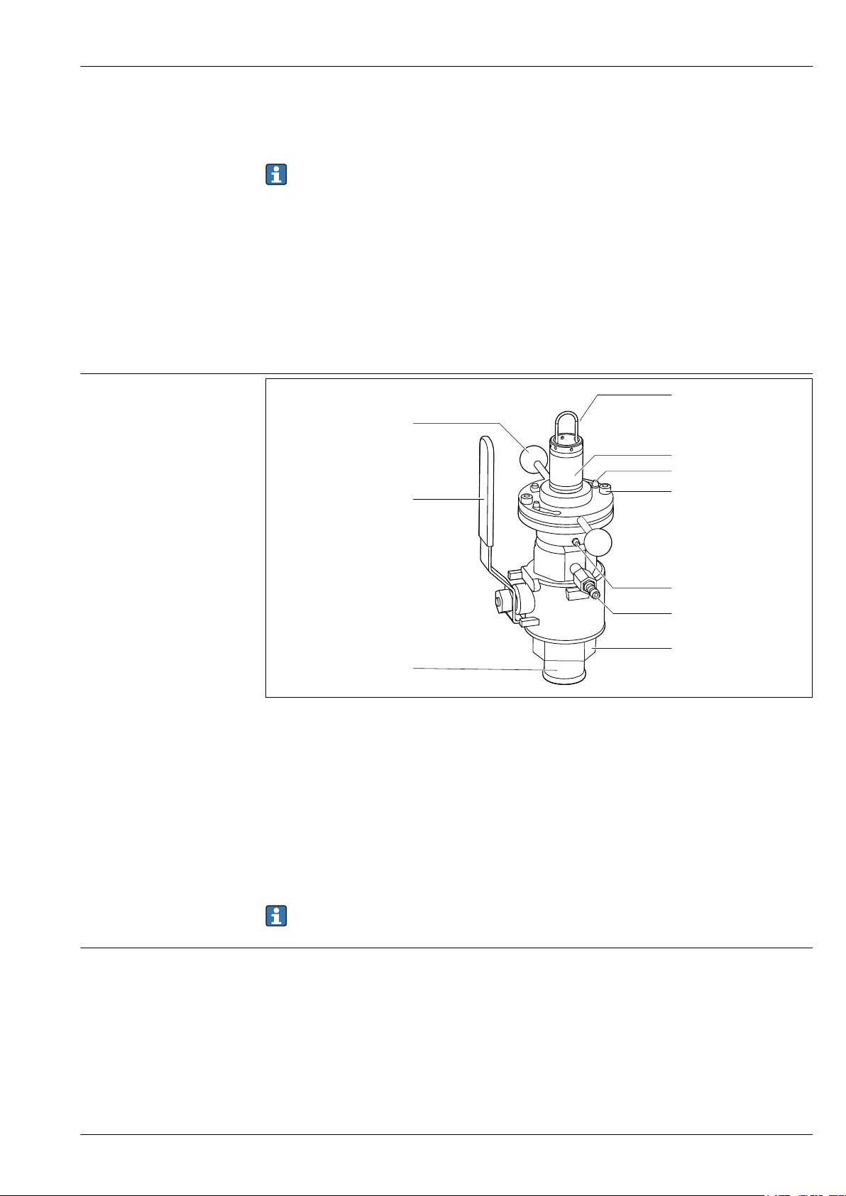
Structure of the assembly
Function and system design
The assembly is operated manually.
The vent cock or the the rinse connections (if used) are in open contact with the medium in the
measuring position and when the assembly is retracted/inserted, and are therefore exposed to
the process pressure.
The vent cock or the rinse connections (if used) must be closed when inserting/retracting the
assembly.
In the service position (sensor moved back into the assembly as far as possible and ball valve closed),
the assembly is sealed from the process by the ball valve.
This means that cleaning, calibration or sensor replacement can be performed without interrupting
the process.
The assembly can be inserted/retracted manually at process conditions up to a process pressure of
approx. 2 bar (29 psi).
A0038438
1 Assembly in operational state (ball valve open)
1 Bracket for sensor holder
2 Sensor holder
3 Bayonet lock
4 Securing screws
5 Grease nipple
6 Ball valve/valve for venting or rinse connection
7 Process connection
8 Retraction pipe
9 Hand lever for opening/closing the ball valve
10 Handles
An additional rinse chamber valve can be mounted in the locking screw opposite the vent valve.
Structure of the sensor holder
The sensor holder is used to position the sensor correctly in order to ensure correct measuring
accuracy.
If the sensor is not positioned correctly, the ball valve may be blocked or the sensor may be located in
the dead space as a result.
3
Page 4
2
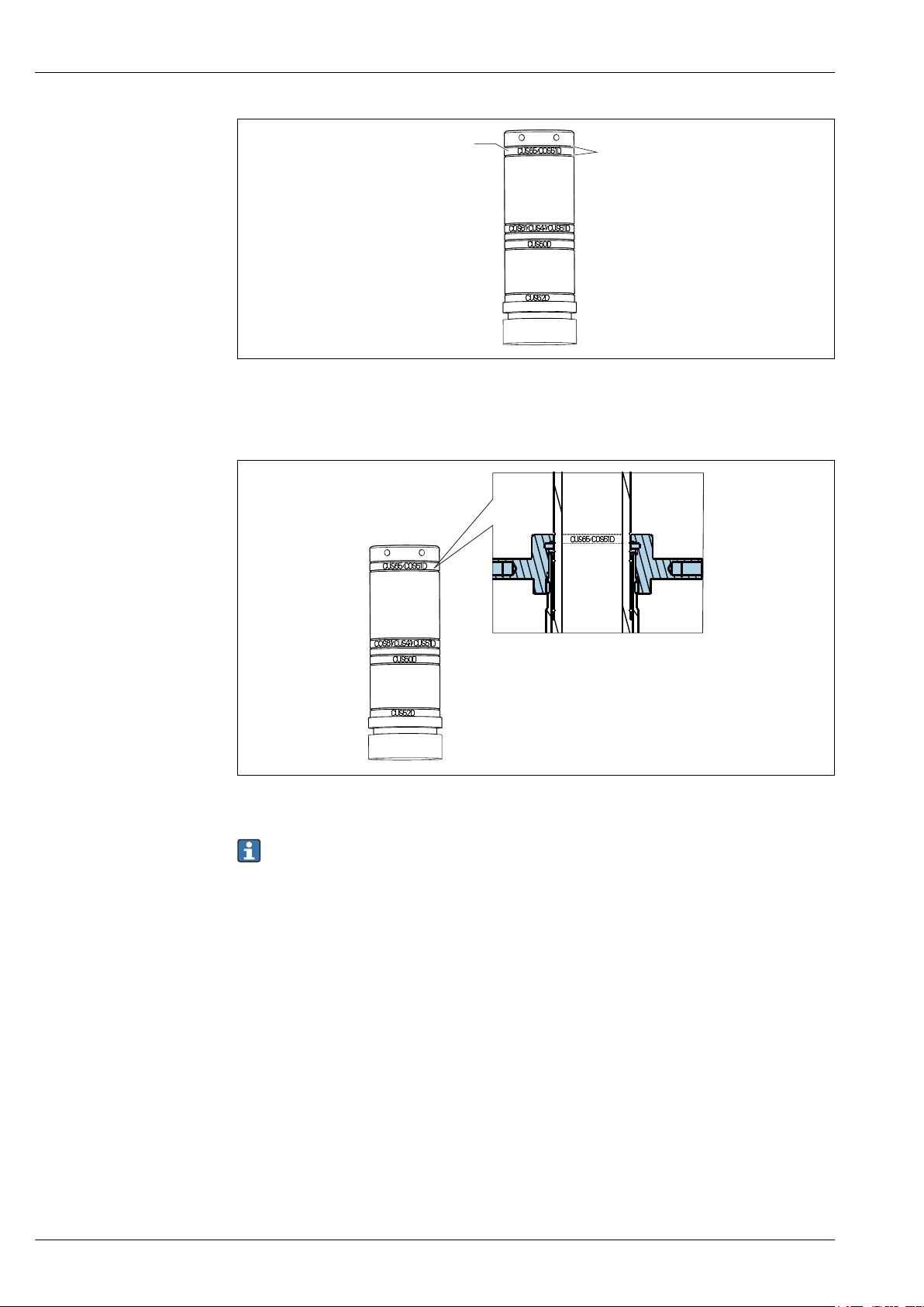
2 Short sensor holder
1 Mounting position of the bayonet nut to hold the relevant sensor
2 Grooves of the safety rings to mount the bayonet nut
Cleanfit COA451
A0038451
A0038479
3 Mounting position of the bayonet nut for CUS65D or COS51D
The name indicated on the holder serves as a mounting aid. The bayonet nut covers over the
marking for the selected sensor position.
4
Page 5

Cleanfit COA451
1
3
4
2
Measuring system
4 Orientations, schematic
1 Sensor (see Accessories)
2 Transmitter
3 Retractable assembly
4 Direction of flow
The orientation depends on the sensor head. Pay attention to the Operating Instructions for the
relevant sensor. An inclination of at least 15° is recommended for amperometric sensors
Make sure to avoid a siphon effect at the rinse chamber outlet. The inflow to the rinse chamber
‣
is always from below.
A0038660
Orientation
Installation
The following diagram shows different installation positions in pipes, and indicates whether they are
permitted or not.
A0038661
5 Schematic of installation positions and orientations
Ideally, the assembly should be mounted in an ascending pipe. Installation in a horizontal pipe is
‣
also possible.
• Install the sensor in places with uniform flow conditions.
• Do not install the sensor in places where air may collect or foam bubbles form or where suspended
particles may settle.
• Avoid installation in the down pipe.
• Avoid fittings downstream from pressure reduction stages which can lead to outgassing.
Installation instructions
Install the assembly in places with uniform flow conditions. The minimum pipe diameter is DN
‣
80.
The installation instructions depend on the sensor used.
Detailed installation instructions are provided in both the Technical Information and in the
Operating Instructions for the particular sensor.
5
Page 6

Environment
8070605040
30
2010
2
4
6
8
10
29
58
87
116
p
p
[psi]
[bar]
176158140
122
104
86
6850
T[°C]
T[°F]
A
85
185
Cleanfit COA451
Ambient temperature
Medium temperature
Medium pressure
Pressure-temperature ratings
0 to 50 °C (32 to 122 °F)
Process
0 to 85 °C (32 to 185 °F)
Max. 10 bar (145 psi)
For manual insertion/retraction of the assembly, the medium pressure must not exceed 2 bar
(29 psi)! Also take the process conditions of the sensor used into consideration!
6 Pressure/temperature ratings
A Range in which the assembly can be operated manually
A0038761
6
Page 7

Cleanfit COA451
226 (8.90)
Ø 49.3
(1.94)
X0
100
(3.94)
Ø 46
(1.81)
106
(4.17)
1 (0.04)
X1
311 (12.24)
67
(2.64)
185 (7.28)
270 (10.63)
109.5 (4.31)
92 (3.62)
115.5 (4.55)
Ø 86 (3.39)
Ø 91 (3.58)
X0
Mechanical construction
Dimensions Assembly with G2 thread and weld-in adapter in measuring position (long and short stroke)
A0038481
7 Dimensions in mm (in)
X0,X1Dimensions depend on the sensor
7
Page 8

Cleanfit COA451
101 (3.98)
X2
171
(6.73)
100
(3.94)
32
(1.26)
X2
276 (10.87)
Assembly with G2 thread and weld-in adapter in service position (long and short stroke)
8 Dimensions in mm (in)
X2 Dimensions depend on the sensor
A0038630
8
Page 9

Cleanfit COA451
Ø 49.3
(1.94)
Ø 46
106 (4.17)
X0
100
(3.94)
X1
85
(3.35)
32 (1.26)
226 (8.90)
(1.81)
32
(1.26)
X2
276 (10.87)
100
(3.94)
101 (3.98)
Assembly with flange connection
9 Dimensions in mm (in)
X0,X2Dimensions depend on the sensor
Sensor X0
CUS52D 25 (0.98)
CUS50D 26 (1)
CUS41/ 16 (0.63)
CUS51D 5 (0.2)
COS61D 12 (0.47)
CUS65 21 (0.83)
COS51D 12 (0.47)
Sensor measuring
position
CUS52D 139 (5.47)
CUS50D 110 (4.33)
CUS41/CUS51D,
COS61D
CUS65, COS51D 59 (2.32)
X1
101 (3.98)
A0038651
Sensor service
position, long
CUS52D 638 (25.12)
CUS50D 609 (23.98)
X2
9
Page 10

Cleanfit COA451
9.25
(0.37)
51.4
(2.02)
60.2
(2.37)
89.5
(3.52)
COS51D
CUS65(D)
COS61(D)
CUS41(D)
CUS51D
CUS50D
CUS52D
131
(5.16)
173 (6.81)
182 (7.17)
211 (8.31)
32
(1.26)
Sensor service
position, long
CUS41/CUS51D,
COS61D
CUS65, COS51D 558 (21.97)
Sensor service
position, short
CUS52D 533 (20.98)
CUS50D 504 (19.84)
CUS41/CUS51D,
COS61D
CUS65, COS51D 453 (17.83)
X2
600 (23.62)
X2
495 (19.49)
Sensor holder with sensors
10
10 Dimensions of sensor holder with sensors in mm (in)
A0038478
Page 11

Cleanfit COA451
A
2"
32 (1.26)
a
b
B
C
Process connections
A0038650
11 Dimensions of process connections in mm (in)
A G2" female thread
B G2" female thread with weld-in adapter
C Flange DN 50 / PN 16 (as per EN 1092-1) and flange ANSI 2" / 150 lbs
a DN 50: Ø 125 (4.92), ANSI 2": Ø 120.7 (4.75)
b DN 50: Ø 165 (6.50), ANSI 2": Ø 152.4 (6.00)
Rinse connection and vent cock
Rinse connection nozzles
Connection options:
• 2 x ball valve with hose connection OD 9mm (see "Accessories"). (A ball valve is included in the
delivery for the assembly. On its own it acts as a vent cock.)
• Customer's own rinse connections with G1/8 external thread
• 2 x G1/8 (internal)
Vent cock
Ball valve with hose connection OD 9 mm
CE/PED
Weight
Depending on version: 8 to 11 kg (17.6 to 24.3 lbs)
Materials
Wetted: Viton (seals)
Stainless steel 1.4404 (AISI 316 L)
Nickel-plated brass (vent cock or rinse connection)
Not wetted: Stainless steel 1.4404 (AISI 316 L)
Certificates and approvals
The assembly has been manufactured according to good engineering practice as per Article 4,
Paragraph 3 of the Pressure Equipment Directive 2014/68/EU and is therefore not required to bear
the CE label.
Ordering information
Product page
Product Configurator
www.endress.com/CUA451
On the product page there is a Configure button to the right of the product image.
1. Click this button.
The Configurator opens in a separate window.
11
Page 12

Cleanfit COA451
2. Select all the options to configure the device in line with your requirements.
In this way, you receive a valid and complete order code for the device.
3. Export the order code as a PDF or Excel file. To do so, click the appropriate button on the right
above the selection window.
For many products you also have the option of downloading CAD or 2D drawings of the
selected product version. Click the CAD tab for this and select the desired file type using
picklists.
Scope of delivery
The delivery comprises:
• Assembly in the version ordered
• Operating Instructions
Accessories
Device-specific accessories Sensors
Oxymax COS41
• Oxygen sensor for drinking water and industrial water measurement, amperometric measuring
principle
• Material: POM
• Product Configurator on the product page: www.endress.com/cos41
Technical Information TI00248C
Oxymax COS51D
• Amperometric sensor for dissolved oxygen
• With Memosens technology
• Product Configurator on the product page: www.endress.com/cos51d
Technical Information TI00413C
Oxymax COS61
• Optical oxygen sensor for drinking water and industrial water measurement
• Measuring principle: quenching
• Material: stainless steel 1.4571 (AISI 316Ti)
• Product Configurator on the product page: www.endress.com/cos61
Technical Information TI00387C
12
Oxymax COS61D
• Optical oxygen sensor for drinking water and industrial water measurement
• Measuring principle: quenching
• With Memosens technology
• Product Configurator on the product page: www.endress.com/cos61d
Technical Information TI00387C
Welding socket
Welding socket
• Welding socket for pipe diameter from 80 mm, with combination flange DN 50 / ANSI 2":
• Bores for DN 50 flange: 4 x 90° Ø18 on bolt circle Ø125 (4.92)
• Bores for ANSI 2" flange: 4 x 90° Ø19 on bolt circle Ø121 (4.75)
• Flange seal, 4 screws M16x60, 4 M16 nuts including washers,
• Stainless steel 1.4571 (AISI 316 Ti)
• Order No. 50080249
Page 13

Cleanfit COA451
D
D
D
D
M16x60
75 (2.95)
93 (3.66)
Ø 165 (6.50)
2"
50
(1.97)
3.6 (0.14)
A0038764
12 Welding socket, dimensions in mm (in)
D Markings for bores, DN 50 flange
Welding nipple
• Welding nipple for 2" thread
• Stainless steel 1.4404 (AISI 316 L)
• Order No. 71448684
A0038763
13 Welding nipple, dimensions in mm (in)
Welding rinse socket DN 65
• For automatic spray cleaning of CUS51D/31/41 sensors in pipes and vessels:
• Bores for DN 50 flange: 4 x 90° Ø18 on bolt circle Ø125
• Bores for ANSI 2" flange: 4 x 90° Ø19 on bolt circle Ø121
• Rinse connection: male thread R¼
• With removable rinse nozzle
• Up to 6 bar (87 psi), 80 °C (176 °F)
• Order No. 51500912
13
Page 14

Cleanfit COA451
D
D
D
D
118 (4.65)
54 (2.13)
Ø 70
33
66 (2.6)
Ø 165 (6.50)
18 (0.71)
(2.76)
(1.3)
Service-specific accessories
Accessory kits
14 Welding rinse socket, dimensions in mm (in)
D Markings for bores, DN 50 flange
Ball valve for rinse chamber
• As rinse connection complementing or replacing the vent cock supplied;
• Order No. 51512982
O-ring set
• Viton + FPM
• Order No. 51512981
A0038762
14
Page 15

Page 16

www.addresses.endress.com
 Loading...