

Page 1
BA01166C/07/EN/01.13
71202122
Products Solutions Services
Operating Instructions
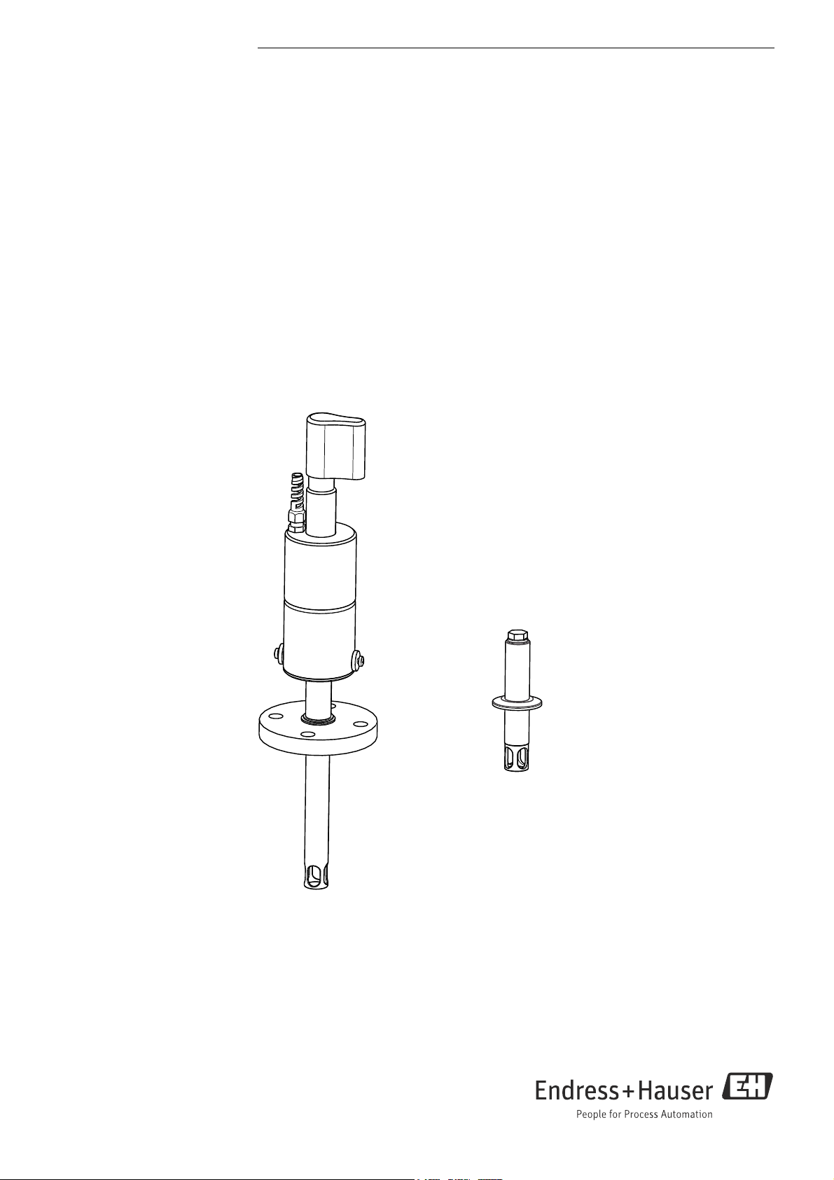
Unifit CPA442
Process assembly
Page 2
Document information
DANGER
!
WARNING
!
CAUTION
!
NOTICE
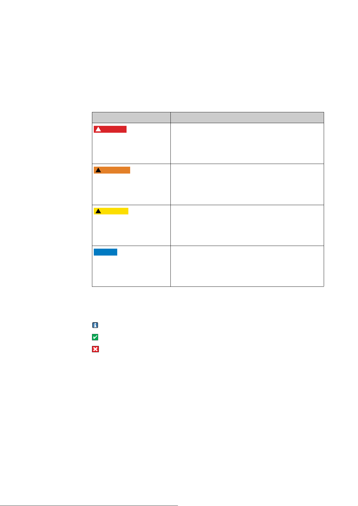
Warning notices
The structure, signal words and safety colors of the warning notices comply with the
specifications of ANSI Z535.6 ("Product safety information in product manuals, instructions
and other collateral materials").
Safety message structure Meaning
This symbol alerts you to a dangerous situation.
Causes (/consequences)
Consequences of noncompliance (if applicable)
‣ Corrective action
Causes (/consequences)
Consequences of noncompliance (if applicable)
‣ Corrective action
Causes (/consequences)
Consequences of noncompliance (if applicable)
‣ Corrective action
Failure to avoid the situation will result in a fatal or serious
injury.
This symbol alerts you to a dangerous situation.
Failure to avoid the situation can result in a fatal or serious
injury.
This symbol alerts you to a dangerous situation.
Failure to avoid this situation can result in minor or more
serious injuries.
Cause/situation
Consequences of noncompliance (if applicable)
‣ Action/note
Symbols used
Additional information, tips
Permitted or recommended
Forbidden or not recommended
This symbol alerts you to situations that can result in
damage to property and equipment.
Endress+Hauser
Page 3

Unifit CPA442
Table of contents
1 Basic safety instructions . . . . . . . . . . . . . 4
1.1 Requirements for personnel . . . . . . . . . . . . . . . . . . 4
1.2 Designated use . . . . . . . . . . . . . . . . . . . . . . . . . . . . . 4
1.3 Workplace safety . . . . . . . . . . . . . . . . . . . . . . . . . . . 4
1.4 Operational safety . . . . . . . . . . . . . . . . . . . . . . . . . . . 4
1.5 Product safety . . . . . . . . . . . . . . . . . . . . . . . . . . . . . . 4
2 Incoming acceptance and product
identification . . . . . . . . . . . . . . . . . . . . . . 5
2.1 Incoming acceptance . . . . . . . . . . . . . . . . . . . . . . . . 5
2.2 Product identification . . . . . . . . . . . . . . . . . . . . . . . . 5
2.3 Scope of delivery . . . . . . . . . . . . . . . . . . . . . . . . . . . . 5
3 Installation . . . . . . . . . . . . . . . . . . . . . . . . 6
3.1 Installation conditions . . . . . . . . . . . . . . . . . . . . . . . 6
3.2 Installation instructions . . . . . . . . . . . . . . . . . . . . . . 9
3.3 Post-installation check . . . . . . . . . . . . . . . . . . . . . 11
4 Maintenance . . . . . . . . . . . . . . . . . . . . . . 12
4.1 Cleaning the assembly . . . . . . . . . . . . . . . . . . . . . 12
4.2 Cleaning agent . . . . . . . . . . . . . . . . . . . . . . . . . . . . 12
4.3 Leak monitoring (optional) . . . . . . . . . . . . . . . . . 13
4.4 Replacing the seals . . . . . . . . . . . . . . . . . . . . . . . . 13
5 Repair . . . . . . . . . . . . . . . . . . . . . . . . . . . . 15
5.1 Replacing damaged parts . . . . . . . . . . . . . . . . . . . 15
5.2 Spare parts kits . . . . . . . . . . . . . . . . . . . . . . . . . . . 15
5.3 Return . . . . . . . . . . . . . . . . . . . . . . . . . . . . . . . . . . . 16
5.4 Disposal . . . . . . . . . . . . . . . . . . . . . . . . . . . . . . . . . 16
6 Accessories . . . . . . . . . . . . . . . . . . . . . . . 17
6.1 Seals . . . . . . . . . . . . . . . . . . . . . . . . . . . . . . . . . . . . 17
6.2 Installation accessories . . . . . . . . . . . . . . . . . . . . . 17
6.3 Sensors . . . . . . . . . . . . . . . . . . . . . . . . . . . . . . . . . . 18
7 Technical data . . . . . . . . . . . . . . . . . . . .20
7.1 Environment . . . . . . . . . . . . . . . . . . . . . . . . . . . . . 20
7.2 Process . . . . . . . . . . . . . . . . . . . . . . . . . . . . . . . . . . 20
7.3 Mechanical construction . . . . . . . . . . . . . . . . . . . 21
Index. . . . . . . . . . . . . . . . . . . . . . . . . . . . . 22
Endress+Hauser 3
Page 4

Basic safety instructions Unifit CPA442
1 Basic safety instructions
1.1 Requirements for personnel
Installation, commissioning, operation and maintenance of the measuring system must
‣
only be carried out by specially trained technical personnel.
‣ The technical personnel must be authorized to perform such tasks by the owner-
operator.
‣ The electrical connection must only be performed by an electrical technician.
‣ Technical personnel must have read and understood these Operating Instructions and
must adhere to them.
‣ Faults at the measuring point may only be rectified by authorized and specially trained
personnel.
Repairs not described in the Operating Instructions supplied may only be carried out
directly at the manufacturer’s or by the service organization.
1.2 Designated use
The Unifit CPA442 process assembly is designed for the installation of 12 mm sensors in
tanks, bio-reactors and pipelines.
Thanks to its mechanical construction, operation in pressurized systems is possible (see
"Technical data").
Any use other than the one described here compromises the safety of persons and the entire
measuring system and is not permitted.
The manufacturer is not liable for damage caused by improper or non-designated use.
1.3 Workplace safety
As the user, you are responsible for complying with the following safety conditions:
• Explosion protection guidelines (only devices approved for use in explosion hazardous
areas)
• Installation specifications
• Local standards and regulations
1.4 Operational safety
Before commissioning the entire measuring point, make sure all the connections are
‣
correct. Ensure that electrical cables and hose connections are not damaged.
‣ Do not operate damaged products, and secure them against unintentional
commissioning. Mark the damaged product as defective.
‣ If faults cannot be rectified, the products must be taken out of service and secured against
unintentional commissioning.
1.5 Product safety
The product is designed to meet state-of-the-art safety requirements, has been tested and
left the factory in a condition in which it is safe to operate.
The applicable regulations and European standards have been considered.
4 Endress+Hauser
Page 5

Unifit CPA442 Incoming acceptance and product identification
2 Incoming acceptance and product
identification
2.1 Incoming acceptance
• Make sure the packaging is undamaged!
• Inform the supplier about damage to the packaging. Keep the damaged packaging until
the matter has been settled.
• Make sure the contents are undamaged!
• Inform the supplier about damage to the delivery contents. Keep the damaged products
until the matter has been settled.
• Check the delivery to make sure nothing is missing. Compare it against the shipping
documents and your order.
• Pack the product for storage and transportation in such a way that it is reliably protected
against impact and moisture. The original packaging provides optimum protection.
Furthermore, the permitted ambient conditions must also be observed (see "Technical
data").
• If you have any questions, contact your supplier or your local sales center.
2.2 Product identification
2.2.1 Nameplate
The nameplate contains the following information:
• Manufacturer data
•Order code
• Extended order code
• Serial number
• Operating conditions
•Safety symbols
Compare the order code indicated on the nameplate with your order.
2.2.2 Identifying the product
The order code and serial number of your device can be found in the following locations:
•On the nameplate
• In the shipping documents
To discover what product version you have, enter the order code on the nameplate into
the search screen at the following address:
www.products.endress.com/order-ident
2.3 Scope of delivery
The scope of delivery comprises:
• Ordered assembly version
• Operating Instructions, English
• Process seal for process connections A, B, M and N
If you have any questions, contact your supplier or your local sales center.
Endress+Hauser 5
Page 6
Installation Unifit CPA442
15°
15°
A B
10°
10°
C
3Installation
3.1 Installation conditions
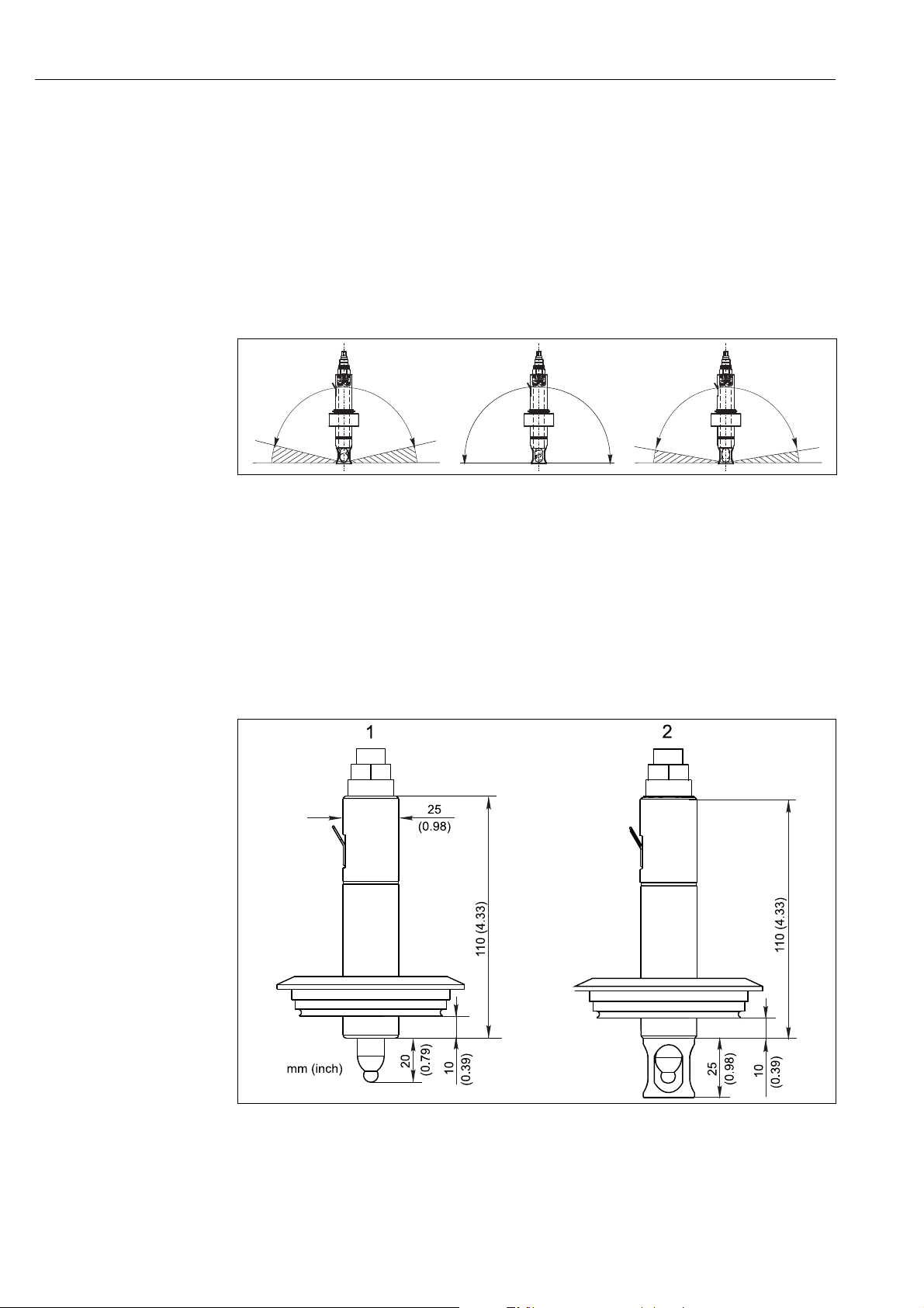
3.1.1 Installation angle
A
Glass sensor:
B
ISFET pH sensor:
C
Oxygen sensor:
Fig. 1: Permitted installation angles depending on the sensor
Installation angle of at least 15° from the horizontal
No restrictions, recommended 0 ... 180°
Installation angle of at least 10° from the horizontal
a0001792
• The assembly can only be installed when the tank is empty and the process is
unpressurized.
• The assembly is designed for mounting on tanks and pipes. Suitable sockets must be
available for this.
• The mounting seal that seals the adapter from the process socket must be provided by the
customer (except for versions A, B, M and N, DN 25 Standard and DN 25 B.Braun Port).
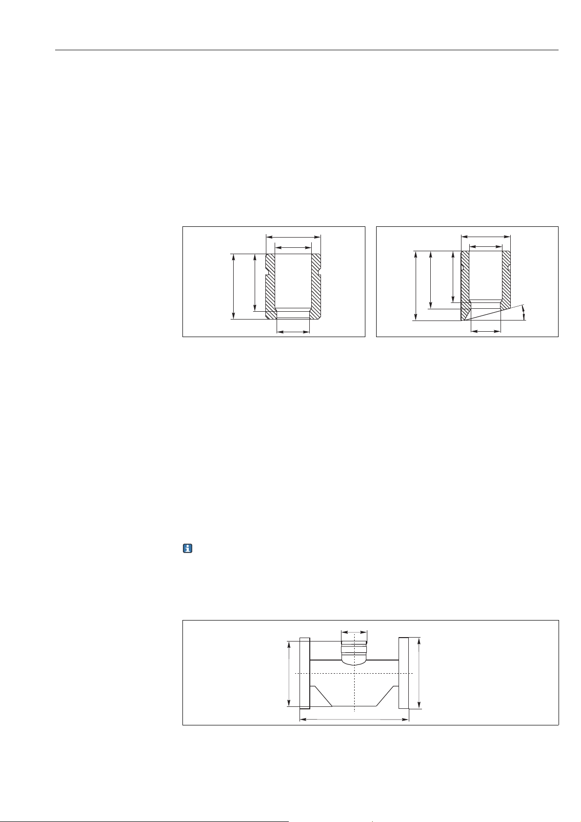
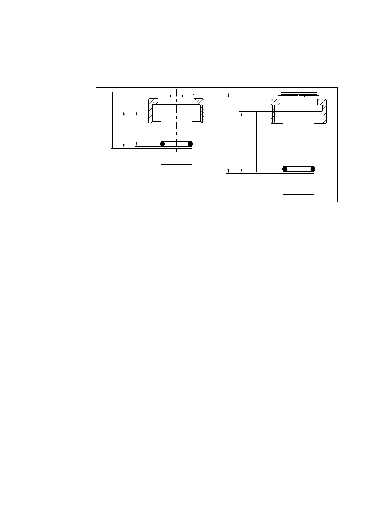
3.1.2 Dimensions
Fig. 2: Dimensions (1 = version G, 2 = Varivent)
1 Without sensor protection guard
2 With sensor protection guard
6 Endress+Hauser
a0019357
Page 7
Unifit CPA442 Installation
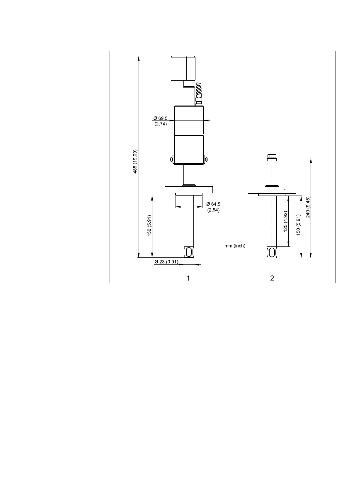
Fig. 3: Dimensions (version V, flange)
1 With sensor protection cover
2 Without sensor protection cover
a0019353
Endress+Hauser 7
Page 8
Installation Unifit CPA442
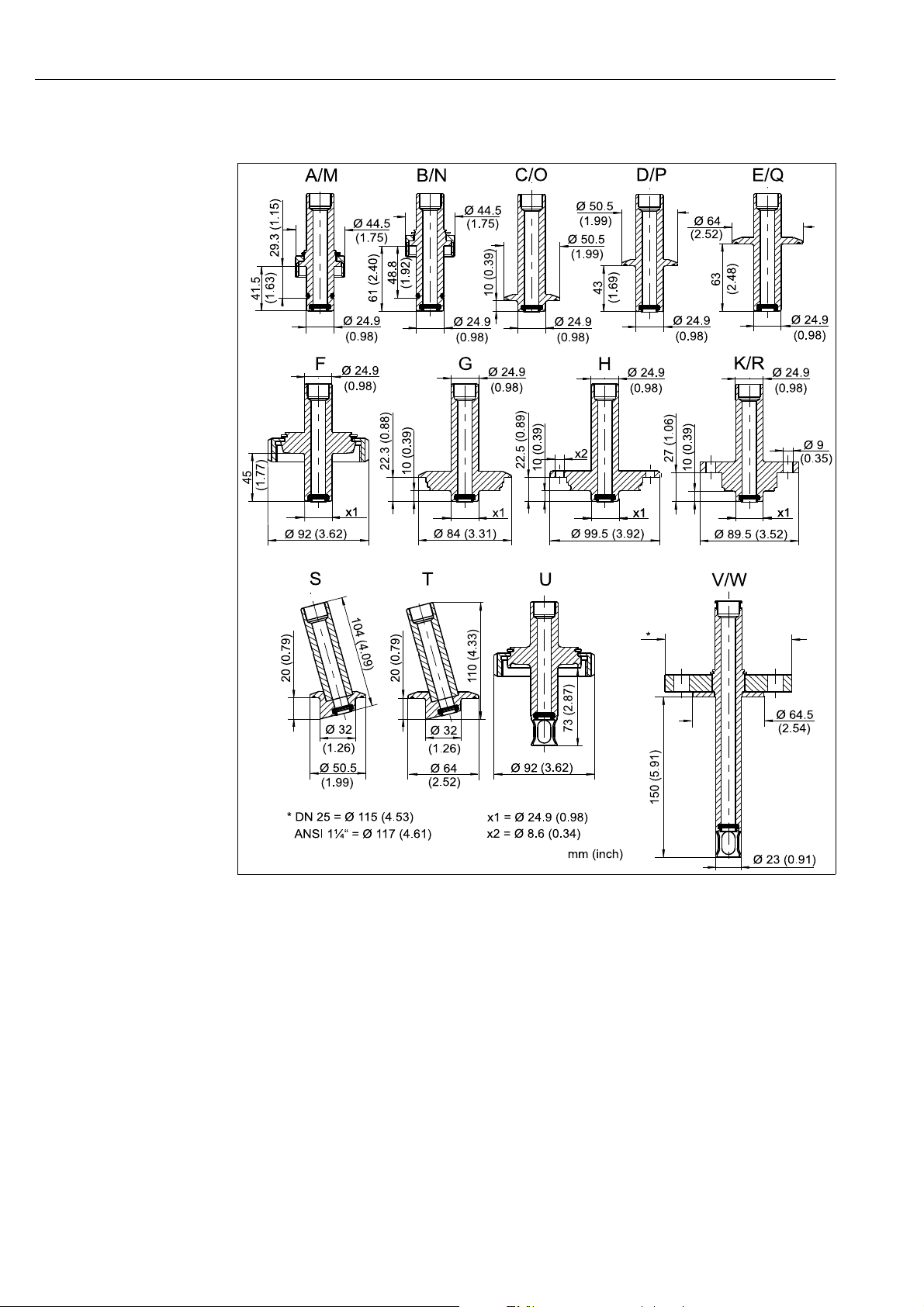
3.1.3 Process connections
a0019356
Fig. 4: Process connections
DN 25 standard / 41.5 mm (1.6" ) / without PM
DN 25 standard / 41.5 mm (1.6" ) / with PM
A
DN 25 B.Braun port / 61 mm (2.4" ) / with PM
B
Clamp 1.5" / 10 mm (0.4" ) / with PM
C
Clamp 1.5" / 43 mm (1.7") / with PM
D
Clamp 2" / 63 mm (2.5" ) / with PM
E
Dairy fitting DN 50 DIN 11851 / 45 mm (1.8") / with
F
PM
Varivent DN 40-125 / 10 mm (0.4" ) / with PM
G
APV DN 40-100 / 10 mm (0.4") / with PM
H
Neumo BioControl D 50 / 10 mm (0.4") / with PM
K
M
DN 25 B.Braun port / 61 mm (2.4" ) / without PM
N
Clamp 1.5" / 10 mm (0.4" ) / without PM
O
Clamp 1.5" / 43 mm (1.7") / without PM
P
Clamp 2" / 63 mm (2.5" ) / without PM
Q
Neumo BioControl D 50 / 10 mm (0.4") / without
R
PM
S
Clamp 1.5" angular 15° / 20 mm (0.8") / without PM
T
Clamp 2" angular 15° / 20 mm (0.8") / without PM
U
DIN 11864-1-A / aseptic DN 50 / without PM
V
Flange DN 25 / 150 mm (5.9") / without PM
W
Flange ANSI 150 lbs 1¼" / 150 mm (5.9") / without
PM
8 Endress+Hauser
Page 9
Unifit CPA442 Installation
3.2 Installation instructions
3.2.1 Measuring system
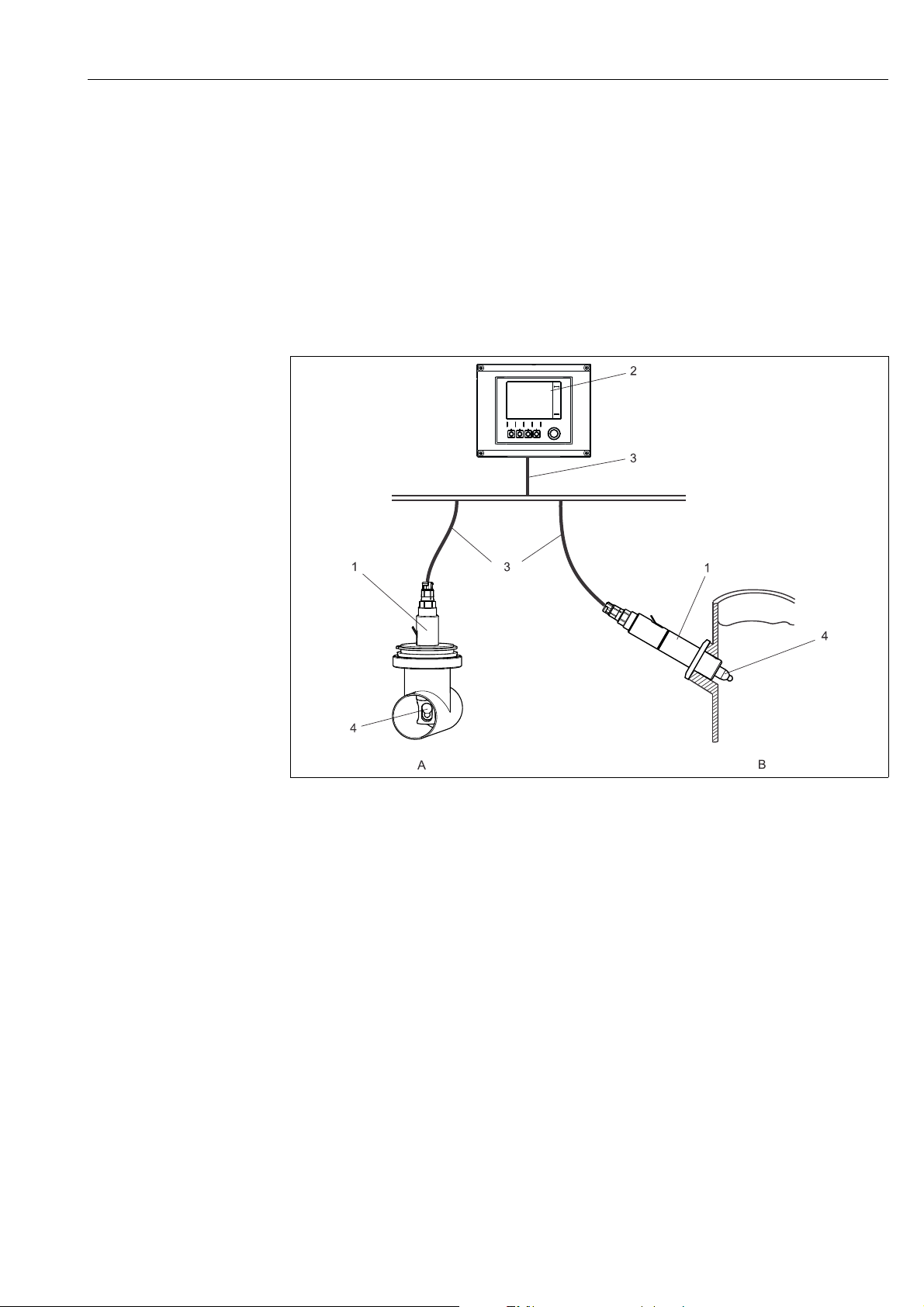
A complete measuring system comprises:
• Unifit CPA442 assembly
• 120 mm sensor, e.g. Orbisint CPS11D or Oxymax COS22D, with or without Memosens
technology, NIR sensors e.g. OUSBT66
• 225 mm sensor for version V and W
• Transmitter, e.g. Liquiline CM44x
•Measuring cable
Fig. 5: Example of a measuring system
1 Unifit CPA442
2 Liquiline CM44x
3Measuring cable
4 Orbisint CPS11D
A Installation in pipe
B Installation in reactor
a0019355
Endress+Hauser 9
Page 10
Installation Unifit CPA442
WARNING
!
1
2
3
3.2.2 Installing the assembly in the process
If medium escapes, this poses a risk of injury from high pressure, high temperature or
contact with chemicals.
‣ Wear protective clothing, gloves and goggles.
‣ Only mount the assembly on empty and unpressurized tanks or pipes.
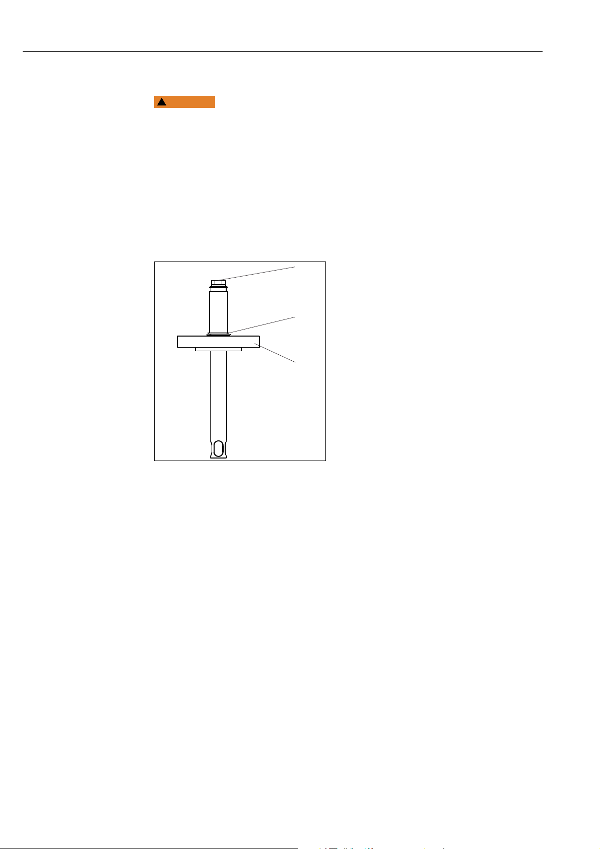
1. Make sure the seal between the assembly and process adapter sealing surface is seated
and positioned correctly.
2. Secure the assembly to the tank or pipe with the process connection. In the case of
versions A, B, M and N, only tighten the union nut finger-tight.
3. If you are not installing a sensor immediately, install the dummy plug instead of the
sensor.
Dummy plug
1
Snap ring
2
Process connection
3
a0019969
Fig. 6: Installation
10 Endress+Hauser
Page 11
Unifit CPA442 Installation
WARNING
!
1
3.2.3 Sensor installation
If medium escapes, this poses a risk of injury from high pressure, high temperature or
contact with chemicals.
‣ Wear protective clothing, gloves and goggles.
‣ Only mount the sensor on empty and unpressurized tanks or pipes.
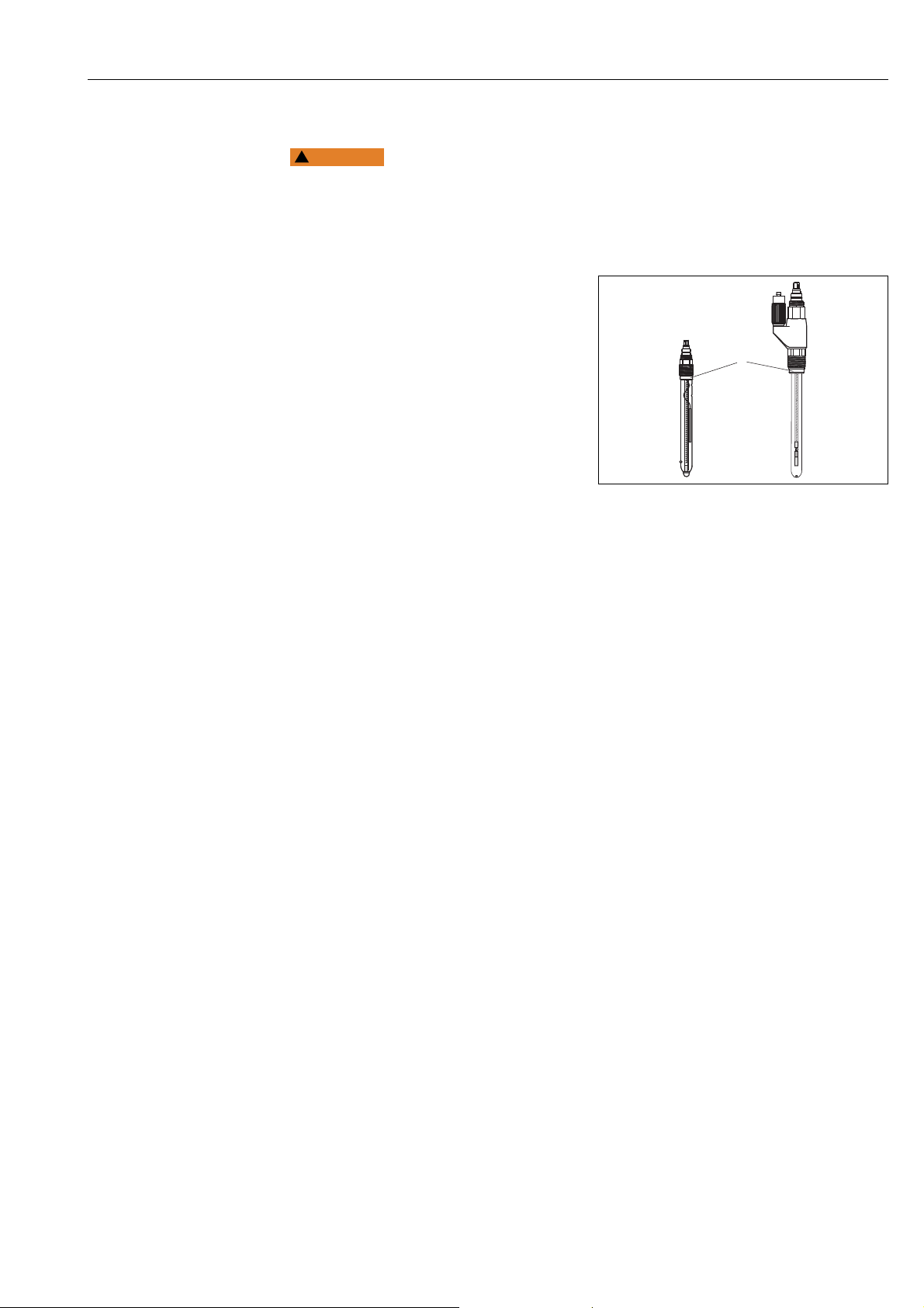
1. Remove the protection cap on the sensor.
Make sure that the O-ring and thrust
collar ( å 7, item 1) are present.
2. Immerse the sensor shaft in water. This
makes installation easier.
3. Remove the dummy plug.
4. Screw in the sensor:
– first screw it in finger-tight,
– then tighten it by approx. ¼ rotation
with a socket wrench (17 mm AF).
5. Connect the measuring cable to the
sensor.
6. For KCl sensors: connect the KCl supply
line.
Fig. 7: Sensor installation
1 Thrust collar with O-ring
a0006214
3.3 Post-installation check
• After installation, check all the connections to ensure they are secure and leak-tight.
• Ensure that the hoses can only be removed by force.
• Check all hoses for damage.
Endress+Hauser 11
Page 12
Maintenance Unifit CPA442
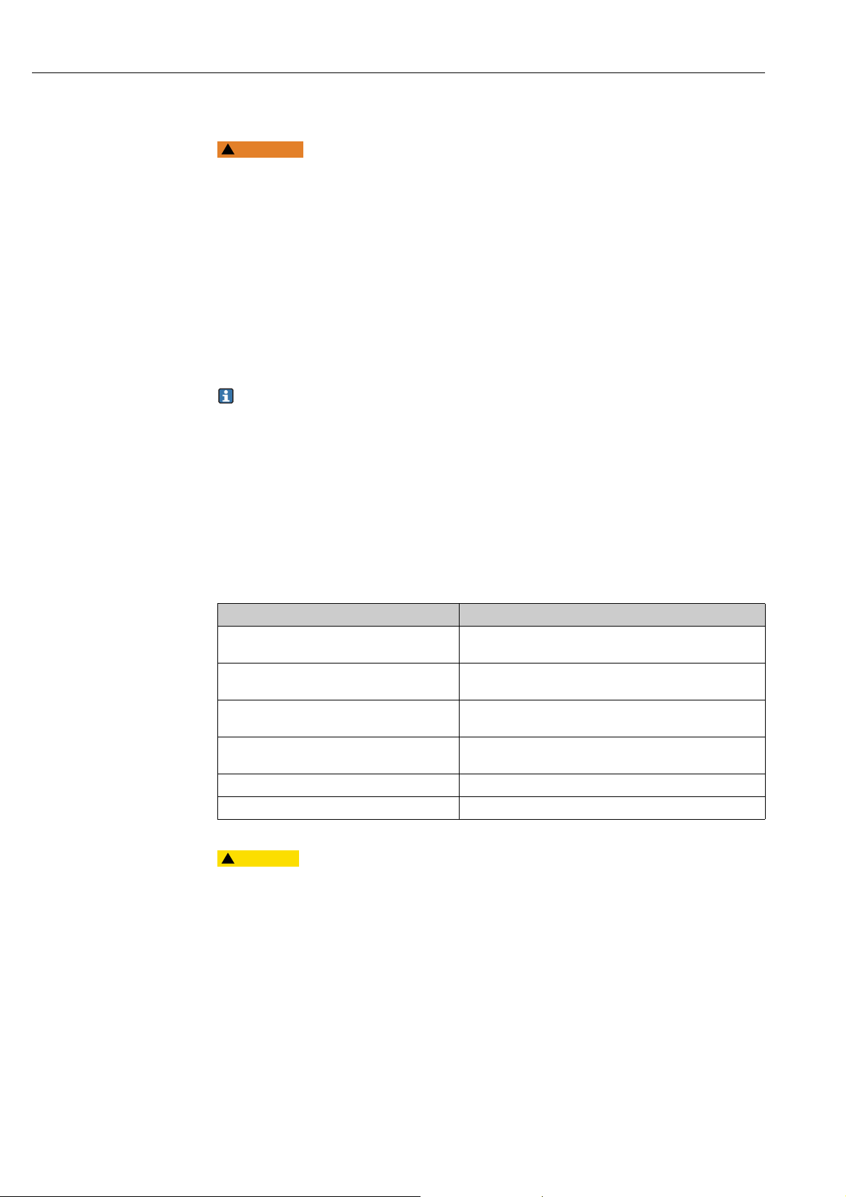
WARNING
!
CAUTION
!
4 Maintenance
Risk of injury if medium escapes!
‣ Before performing any maintenance task, make sure that the process pipe is
unpressurized, empty and rinsed.
4.1 Cleaning the assembly
The assembly must be cleaned regularly to ensure stable and reliable sampling. The
frequency and intensity of the cleaning process depend on the medium.
• Remove light dirt using suitable cleaning solutions (see the "Cleaning agent" section).
• Use a soft brush and a suitable cleaning agent for stubborn dirt.
• For very persistent dirt, soak the parts in a cleaning solution and then clean the parts with
a brush.
A typical cleaning interval for drinking water would be 6 months, for instance.
You can also clean the assembly in-line (CIP).
You can also sterilize the assembly in-line (SIP) if the sensor is SIP-enabled and the assembly
is made from stainless steel or Alloy C22.
The assembly can also be autoclaved with the appropriate sensor.
4.2 Cleaning agent
The choice of cleaning agent depends on the degree and type of fouling. The most common
fouling and the suitable cleaning agents are provided in the following table.
Type of fouling Cleaning agent
Greases and oils Agents containing surfactants (alkaline) or water-soluble
organic solvents (halogen-free, e.g. ethanol)
Lime deposits, metal hydroxide buildup,
lyophobic biological buildup
Sulfide deposits Mixture of 3% hydrochloric acid and thiocarbamide
Proteins deposits Mixture of 3% hydrochloric acid and pepsin (commercially
Fibers, suspended substances Pressurized water, possibly surface-active agent
Light biological deposits Pressurized water
Approx. 3% hydrochloric acid
(commercially available)
available)
Health risk due to solvents
‣ Do not use acetone or organic solvents containing halogen. These solvents can destroy
plastic parts of the sensor and some are also suspected of being carcinogenic (e.g.
chloroform).
12 Endress+Hauser
Page 13
Unifit CPA442 Maintenance
CAUTION
!
1
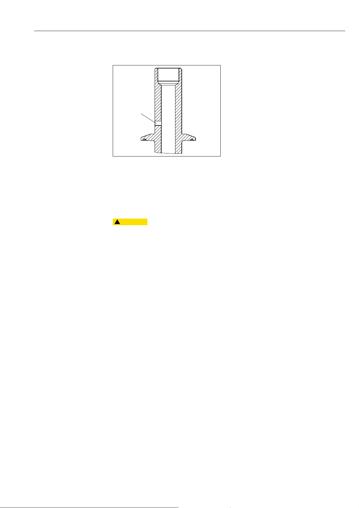
4.3 Leak monitoring (optional)
Check for leaks (visual inspection) at
regular intervals. If medium has escaped at
the monitoring hole, the molded seal must
be replaced.
a0019977
Fig. 8: Leakage monitoring
1 Leak monitoring
4.4 Replacing the seals
To replace the seals in the assembly, you must interrupt the process and remove the entire
assembly.
Residual medium and high temperatures can cause injury
‣ Protect yourself against residual medium and high temperatures when handling parts in
contact with the medium. Wear protective goggles and safety gloves.
Clean the assembly before replacing the seals (see the "Cleaning the assembly" section).
Preparatory steps:
1. Interrupt the process. Watch out for residual medium, residual pressure and high
temperatures.
2. Remove the sensor.
3. Detach the assembly completely from the process connection.
4. Clean the assembly (see the "Cleaning the assembly" section).
Replacing the seals:
Endress+Hauser 13
Page 14
Maintenance Unifit CPA442
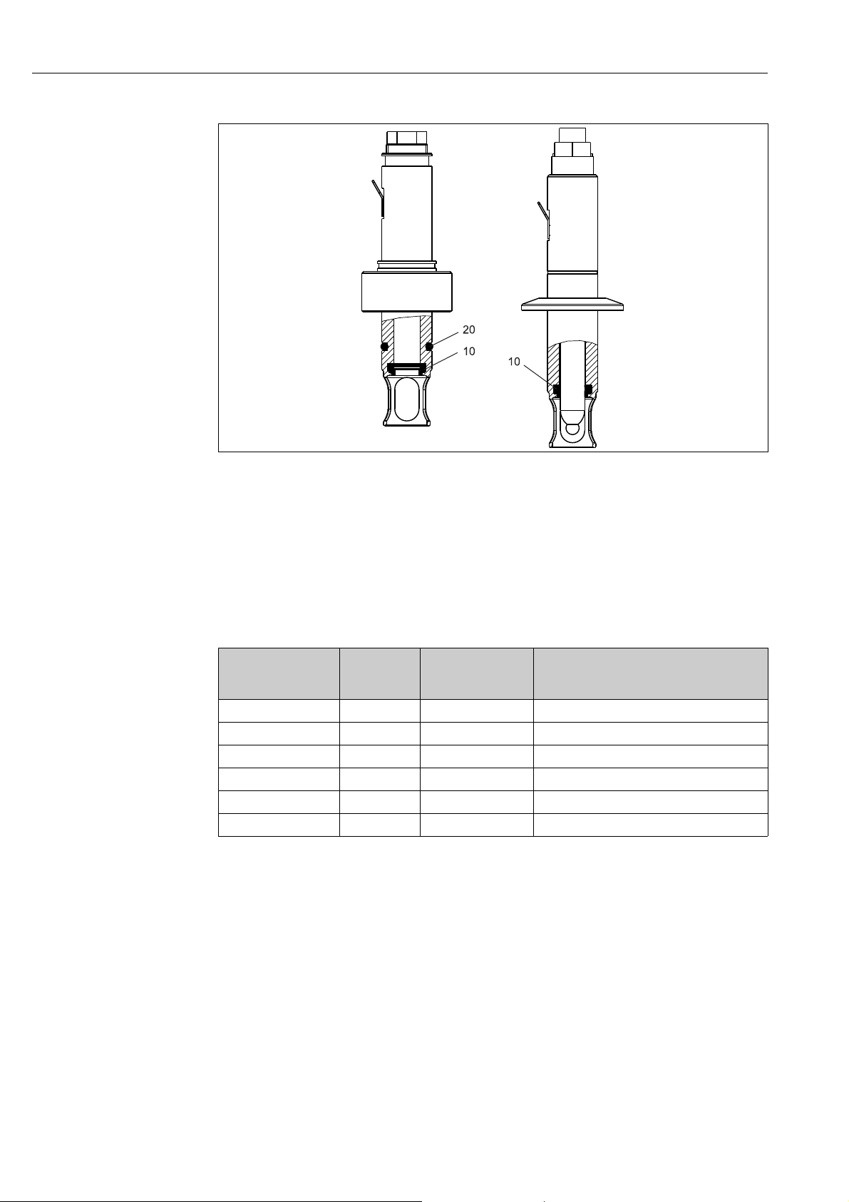
a0019930
Fig. 9: Position of the seals
10 Molded seal for all versions
20 O-ring for process connection version A, B, M and N
1. Coat the new seals with a thin film of grease (e.g. Syntheso Glep1).
2. Replace the seals indicated.
3. Install the sensor into the assembly.
4. Install the assembly again.
Kit No. Kit Item No.
(installation
drawing)
51507170 Item 20 ID 18.66 W 3.53 EPDM, FDA, USP class VI
51507170 Item 10 Molded seal EPDM, FDA, USP class VI
51507169 Item 20 ID 18.66 W 3.53 FKM (Viton), FDA, USP class VI
51507169 Item 10 Molded seal FKM (Viton), FDA, USP class VI
51507171 Item 20 ID 18.66 W 3.53 Silicone, FDA, USP class VI
51507171 Item 10 Molded seal Silicone, FDA, USP class VI
Size Comments/material
14 Endress+Hauser
Page 15
Unifit CPA442 Repair
WARNING
!
5Repair
5.1 Replacing damaged parts
Incorrect repair work can pose a hazard
‣ Damage to the assembly which impacts the pressure safety must only be repaired by
authorized technical personnel.
‣ After every repair and maintenance activity, suitable measures must be taken to check
the assembly and ensure it shows no signs of leaking. Afterwards, the assembly must
again meet the specifications in the technical data.
Replace all other damaged components immediately.
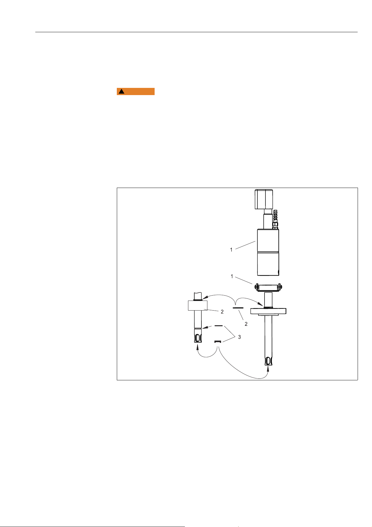
5.2 Spare parts kits
a0019978
Fig. 10: Spare parts
Endress+Hauser 15
Page 16

Repair Unifit CPA442
Please refer to the following table for the order numbers of the spare parts kits based
on the item numbers in å 10.
Item
No.
1 Protection cover with mounting plate 71214966
2
3
Kit name and content Order number
of spare parts kit
Union nut G1¼, brass, with circlip 71214967
Union nut G1¼, stainless steel 1.4571 (AISI 316 Ti), with
circlip
Seal set, EPDM, FDA USP class VI 51507170
Seal set, FKM (Viton), FDA USP class VI 51507169
Seal set, silicone, FDA USP class VI 51507171
71214968
5.3 Return
The product must be returned if repairs or a factory calibration are required, or if the wrong
product has been ordered or delivered. According to legal regulations Endress+Hauser, as an
ISO-certified company, is required to follow certain procedures when handling returned
products that are in contact with the medium.
To ensure swift, safe and professional device returns:
Check the website for information about the return procedure and basic conditions
www.services.endress.com/return-material
5.4 Disposal
Please observe local regulations when disposing of the product.
16 Endress+Hauser
Page 17
Unifit CPA442 Accessories
G1¼
Ø25
44 / 24.5
50/30
Ø28
Ø25
G1¼
Ø28
49/30
44 / 24.5
59/39
15°
G1¼
160 (6.30)
105 (4.13)
DN 25/ PN 16
mm (inch)
6 Accessories
6.1 Seals
• EPDM seal set for CPA442; order no. 51507170
•FKM (Viton
®
) seal set for CPA442; order no. 51507169
• Silicone seal set for CPA442; order no. 51507171
6.2 Installation accessories
a0001799-en a0001800-en
• DN25 safety welding socket, straight, stainless steel 1.4435, L=50;
order no. 51508049
only for CPA442-B******
only for CPA442-N******
• DN25 safety welding socket, angled, stainless steel 1.4435, L=50/60; order no.
51508050
only for CPA442-B******
only for CPA442-N******
• DN25 safety welding socket, straight, stainless steel 1.4435, L=30;
order no. 51508051
only for CPA442-A******
only for CPA442-M******
• DN25 safety welding socket, angled, stainless steel 1.4435, L=30/40; order no.
51508052
only for CPA442-A******
only for CPA442-M******
Already existing standard welding sockets (for CPA440 / CPA441 / CPA460), order no.
50005192 and 50028446, are also suitable for the CPA442 assembly.
Flow vessel DN 25,
• G 1¼ external thread, stainless steel 1.4404 (AISI 316 L);
• order no. 51502801
Endress+Hauser 17
Fig. 11: Flow vessel
a0007567
Page 18
Accessories Unifit CPA442
45 (1.77)
30 (1.18)
28.5 (1.12)
Ø 24.9
(0.98)
65 (2.56)
50 (1.97)
48.5 (1.91)
Ø 24.9
(0.98)
Dummy plug for welding socket,
• Stainless steel 1.4435 (AISI 316 L) with EPDM seal (USP Class VI), G 1¼
• Order no. for socket length 30 mm: 71213701
• Order no. for socket length 50 mm: 71213702
a0020476
Fig. 12: Dummy plug
6.3 Sensors
Orbisint CPS11/CPS11D
• pH sensor for process applications
• Optional SIL version for connection to SIL approved transmitters
• With dirt-repellent PTFE diaphragm
• Ordering per product structure (--> Online configurator, www.products.endress.com/
cps11 or www.products.endress.com/cps11d)
• Technical Information TI028C/07/EN
Orbisint CPS12/CPS12D
• ORP electrode for process applications
• Ordering per product structure (--> Online configurator, www.products.endress.com/
cps12 or www.products.endress.com/cps12d)
• With dirt-repellent PTFE diaphragm
• Technical Information TI367C/07/EN
Ceraliquid CPS41/CPS41D
• pH sensor With ceramics diaphragm and liquid KCl electrolyte
• Ordering per product structure (--> Online configurator, www.products.endress.com/
cps41 or www.products.endress.com/cps41d)
• Technical Information TI079C/07/EN
Ceraliquid CPS42/CPS42D
• ORP electrode With ceramics diaphragm and liquid KCl electrolyte
• Ordering per product structure (--> Online configurator, www.products.endress.com/
cps42 or www.products.endress.com/cps42d)
• Technical Information TI373C/07/EN
Ceragel CPS71/CPS71D
• pH sensor With double chamber reference system and integrated bridge electrolyte
• Ordering per product structure (--> Online configurator, www.products.endress.com/
cps71 or www.products.endress.com/cps71d)
• Technical Information TI245C/07/EN
18 Endress+Hauser
Page 19

Unifit CPA442 Accessories
Ceragel CPS72/CPS72D
• ORP electrode With double chamber reference system and integrated bridge electrolyte
• Ordering per product structure (--> Online configurator, www.products.endress.com/
cps72 or www.products.endress.com/cps72d)
• Technical Information TI374C/07/EN
Orbipore CPS91/CPS91D
• pH sensor With open aperture for media with high dirt load
• Ordering per product structure (--> Online configurator, www.products.endress.com/
cps91 or www.products.endress.com/cps91d)
• Technical Information TI375C/07/EN
Orbipore CPS92/CPS92D
• ORP sensor With open aperture for media with high dirt load
• Ordering per product structure (--> Online configurator, www.products.endress.com/
cps92 or www.products.endress.com/cps92d)
• Technical Information TI435C/07/EN
Tophit CPS471/CPS471D
• Sterilizable and autoclavable ISFET sensor for food and pharmaceuticals, process
technology,
• water treatment and biotechnology;
• Ordering per product structure (--> Online configurator, www.products.endress.com/
cps471 or www.products.endress.com/cps471d)
• Technical Information TI283C/07/EN
Tophit CPS441/CPS441D
• Sterilizable ISFET sensor for media with low conductivity, with
• liquid KCl electrolyte;
• Ordering per product structure (--> Online configurator, www.products.endress.com/
cps441 or www.products.endress.com/cps441d)
• Technical Information TI352C/07/EN
Tophit CPS491/CPS491D
• ISFET sensor with open aperture for media with high dirt load;
• Ordering per product structure (--> Online configurator, www.products.endress.com/
cps491 or www.products.endress.com/cps491d)
• Technical Information TI377C/07/EN
Oxymax COS22D
• Sterilizable sensor for dissolved oxygen
• Order as per product structure (--> Online configurator, www.products.endress.com/
cos22d)
• Technical Information TI446C/07/EN
Endress+Hauser 19
Page 20
Technical data Unifit CPA442
7Technical data
7.1 Environment
Ambient temperature -15 to 80 °C (+5 to 176 °F)
Storage temperature -15 to 60 °C (+5 to 140 °F)
7.2 Process
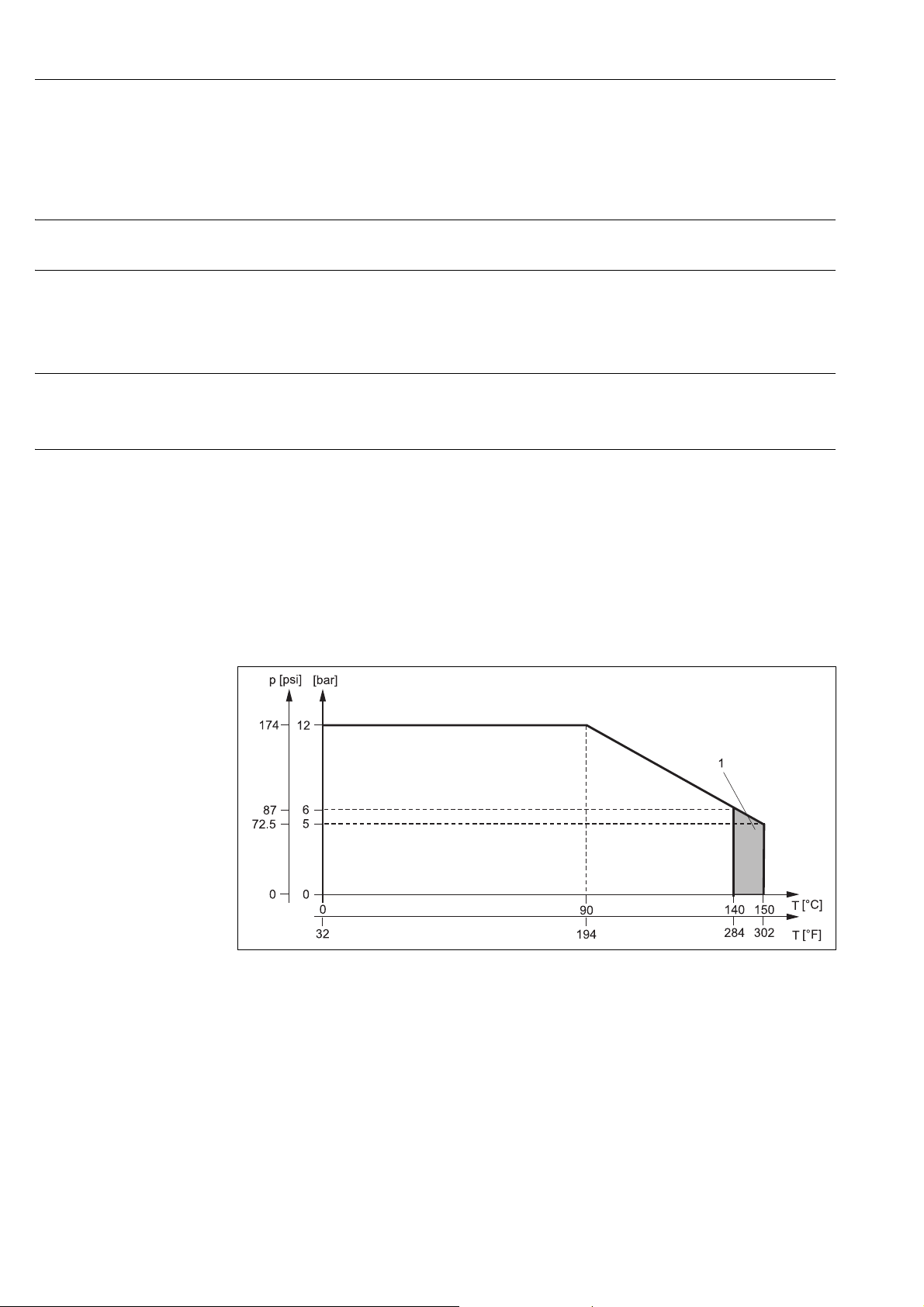
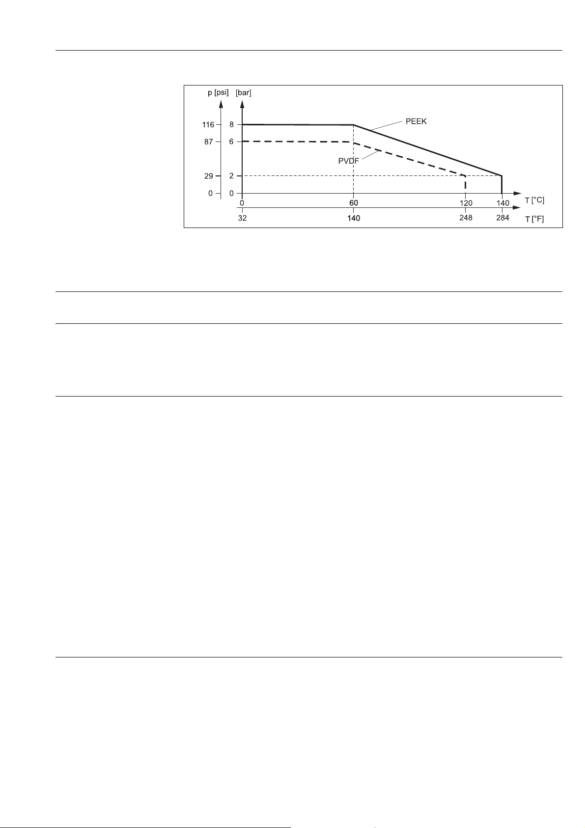
Process temperature
range
Process pressure
Stainless steel and Alloy C22
PEEK
PVDF
Stainless steel and Alloy C22 12 bar (174 psi) up to 90 °C (194 °F)
PEEK 8 bar (116 psi) up to 60 °C (140 °F)
PVDF 6 bar (87 psi) up to 60 °C (140 °F)
–15 to 140 °C (+5 to 284 °F)
–10 to 140 °C (+14 to 284 °F)
–10 to 120 °C (+14 to 248 °F)
6 bar (87 psi) up to 140 °C (284 °F)
5 bar (72.5 psi) at 150 °C (302 °F) max. 60 minutes
2 bar (29 psi) up to 140 °C (284 °F)
2 bar (29 psi) up to 120 °C (248 °F)
7.2.1 Pressure / temperature diagram
a0019452
Fig. 13: Pressure temperature diagram for stainless steel 1.4435 (AISI 316 L) and Alloy C22
1 Short term for sterilization (max. 60 minutes)
20 Endress+Hauser
Page 21
Unifit CPA442 Technical data
a0019453
Fig. 14: Pressure temperature diagram for PEEK and PVDF
7.3 Mechanical construction
Dimensions See the "Installation" section
Weight
Assembly with process connections A to U0.5 to 1.4 kg (1.1 to 3.1 lbs)
Assembly with process connections V
and W
Protection cover: approx. 1.0 kg (2.2 lbs)
Materials In contact with medium
Seals:
Assembly:
Dummy plug (Pg 13.5):
Not in contact with medium
approx. 2.5 kg (5.5 lbs)
EPDM, FDA according to 21CFR 177.2600, USP Class VI
FKM (Viton), FDA according to 21CFR 177.2600, USP
Class VI
Silicone, FDA according to 21CFR 177.2600, USP Class VI
FFKM (Kalrez) on request
Stainless steel 1.4435 (AISI 316 L)
Alloy C22
PVDF
PEEK
PP
Union nut:
Stainless steel 1.4571 (AISI 316 Ti)
optional nickel-plated brass
Protection cover:
POM black
Process connection See the "Installation" section
Endress+Hauser 21
Page 22

Unifit CPA442
Index
C
Cleaning . . . . . . . . . . . . . . . . . . . . . . . . . . . . . . . . . . . . . . . 12
Cleaning agent . . . . . . . . . . . . . . . . . . . . . . . . . . . . . . . . . . 12
D
Designated use. . . . . . . . . . . . . . . . . . . . . . . . . . . . . . . . . . . . 4
Dimensions. . . . . . . . . . . . . . . . . . . . . . . . . . . . . . . . . . . . . . . 6
Disposal. . . . . . . . . . . . . . . . . . . . . . . . . . . . . . . . . . . . . . . . 16
I
Incoming acceptance. . . . . . . . . . . . . . . . . . . . . . . . . . . . . . . 5
Installation . . . . . . . . . . . . . . . . . . . . . . . . . . . . . . . . . . . . . . . 6
Installation angle. . . . . . . . . . . . . . . . . . . . . . . . . . . . . . . . . . 6
Installation conditions . . . . . . . . . . . . . . . . . . . . . . . . . . . . . 6
Installation instructions . . . . . . . . . . . . . . . . . . . . . . . . . . . . 9
L
Leakage monitoring . . . . . . . . . . . . . . . . . . . . . . . . . . . . . 13
M
Maintenance . . . . . . . . . . . . . . . . . . . . . . . . . . . . . . . . . . . 12
Measuring system . . . . . . . . . . . . . . . . . . . . . . . . . . . . . . . . . 9
N
Nameplate . . . . . . . . . . . . . . . . . . . . . . . . . . . . . . . . . . . . . . . 5
O
Operational safety . . . . . . . . . . . . . . . . . . . . . . . . . . . . . . . . . 4
O-rings . . . . . . . . . . . . . . . . . . . . . . . . . . . . . . . . . . . . . . . . 13
P
Post-installation check . . . . . . . . . . . . . . . . . . . . . . . . . . . 11
Process connections . . . . . . . . . . . . . . . . . . . . . . . . . . . . . . . 8
Product identification . . . . . . . . . . . . . . . . . . . . . . . . . . . . . . 5
Product safety . . . . . . . . . . . . . . . . . . . . . . . . . . . . . . . . . . . . 4
R
Requirements for personnel. . . . . . . . . . . . . . . . . . . . . . . . . 4
Return . . . . . . . . . . . . . . . . . . . . . . . . . . . . . . . . . . . . . . . . . 16
S
Safety instructions. . . . . . . . . . . . . . . . . . . . . . . . . . . . . . . . . 4
Scope of delivery . . . . . . . . . . . . . . . . . . . . . . . . . . . . . . . . . . 5
Seals . . . . . . . . . . . . . . . . . . . . . . . . . . . . . . . . . . . . . . . . . . 13
Sensor installation. . . . . . . . . . . . . . . . . . . . . . . . . . . . . . . 11
Service. . . . . . . . . . . . . . . . . . . . . . . . . . . . . . . . . . . . . . . . . 12
Spare parts kits . . . . . . . . . . . . . . . . . . . . . . . . . . . . . . . . . 15
Symbols. . . . . . . . . . . . . . . . . . . . . . . . . . . . . . . . . . . . . . . . . . 2
T
Technical data . . . . . . . . . . . . . . . . . . . . . . . . . . . . . . . . . . 20
W
Warning notices . . . . . . . . . . . . . . . . . . . . . . . . . . . . . . . . . . 2
Workplace safety. . . . . . . . . . . . . . . . . . . . . . . . . . . . . . . . . . 4
22 Endress+Hauser
Page 23

Unifit CPA442
Endress+Hauser 23
Page 24

www.addresses.endress.com
71202122
 Loading...