

Page 1
EMU QS(En).fm Page 1 Thursday, October 26, 2006 11:09 AM
1 - Introduction
Thank you for purchasing the E-MU 1212M, E-MU 1616 or E-MU 1616M PCI digital audio system. W e’ve designed this
E-MU Digital Audio System to be flexible, intuitive and above all, to provide you with uncompromising sound quality. All three
systems provide high-end studio-quality, 24-bit/192kHz multi-channel recording and playback at a truly astounding price.
System Requirements
®
• Intel
• Intel, AMD or 100% compatible motherboard & chipset
• Windows XP (SP2), Windows 2000 (SP4), or x64
• 256 MB System RAM
• 900 MB of free hard disk space for full installation.
•Available PCI 2.1 compliant slot (Two slots needed for E-MU 1212M)
• XVGA Video (1024 x 768)
• CD-ROM/CD-RW or DVD-ROM drive required for software installation.
• Headphones or amplified speakers
Other applications may have higher system requirements or may require a microphone.
or AMD
®
processor operating at 1 GHz or faster
Package Contents
E-MU 1212M PCI
• E-MU 1010 PCI card
• E-MU 0202 I/O Daughter card
• I/O Daughter card ribbon cable
• (2) mini MIDI cables
• E-MU Digital Audio System
Software/Driver Install CD-ROM
•Production Tools Software
Bundle CD-ROM
• This Quick Start Guide
E-MU 1616 PCI E-MU 1616M PCI
• E-MU 1010 PCI card
• E-MU MicroDock
• EDI (E-MU Digital Interface) cable
• Universal Power Adapter
• MIDI Breakout Cable
• E-MU Digital Audio System Software/
Driver Install CD-ROM
•Prod. Tools Software Bundle CD-ROM
• This Quick Start Guide
• E-MU 1010 PCI card
• E-MU MicroDock M
• EDI (E-MU Digital Interface) cable
• Universal Power Adapter
• MIDI Breakout Cable
• E-MU Digital Audio System Software/
Driver Install CD-ROM
•Prod. Tools Software Bundle CD-ROM
• This Quick Start Guide
Quick Start Guide - Getting Started - 1
Page 2

EMU QS(En).fm Page 2 Thursday, October 26, 2006 11:09 AM
Safety First!
As you install hardware components, observe the following general precautions to avoid damage to your equipment and
yourself.
•To avoid possible permanent damage to your hardware, make sure that all connections are made to the E-MU 1010
card and the MicroDock with the host computer’s power off.
Unplug the computer’s power cable to make sure that the computer is not in sleep mode .
•Take car e to avoid static damage to any components of your system. Internal computer surfaces, the E-MU 1010 PCI
board and the interfaces are susceptible to electrostatic discharge, commonly known as “static”. Electrostatic
discharge can damage or destroy electronic devices. Here are some procedures you can follow when handling
electronic devices in order to minimize the possibility of causing electrostatic damage:
•Avoid any unnecessary movement, such as scuffing your feet when handling electronic devices, since most
movement can generate additional charges of static electricity.
• Minimize the handling of the PCI card. Keep it in its static-free package until needed. Transport or store the board
only in its protective package.
• When handling a PCI card, avoid touching its connector pins. Try to handle the board by its edges only.
• Before installing a PCI card into your computer, you should be gr ounded. Use a gr ound strap to dischar ge any static
electric charge built up on your body. The ground strap attaches to your wrist and any unpainted metal surface
within your computer.
Getting More Information
Refer to the various online Help files and the Owner’s Manual (on CD) for detailed information on the E-MU Digital Audio
System and various software applications.
After Software Installation: Click on the E-MU icon in the Windows SysTray to open PatchMix DSP, then click the
in the upper right corner to open the complete operation manual.
?
Technical Support
As the E-MU Digital Audio System expands, you’ll want to keep up with the latest software and new options for your E-MU
Digital Audio System. You can find all of this—plus other helpful information—at www.emu.com . Refer to your Owner’s
Manual on CD for the technical support phone number.
2 - E-MU PCI Digital Audio System
Page 3
EMU QS(En).fm Page 3 Thursday, October 26, 2006 11:09 AM
2 - Hardware Installation
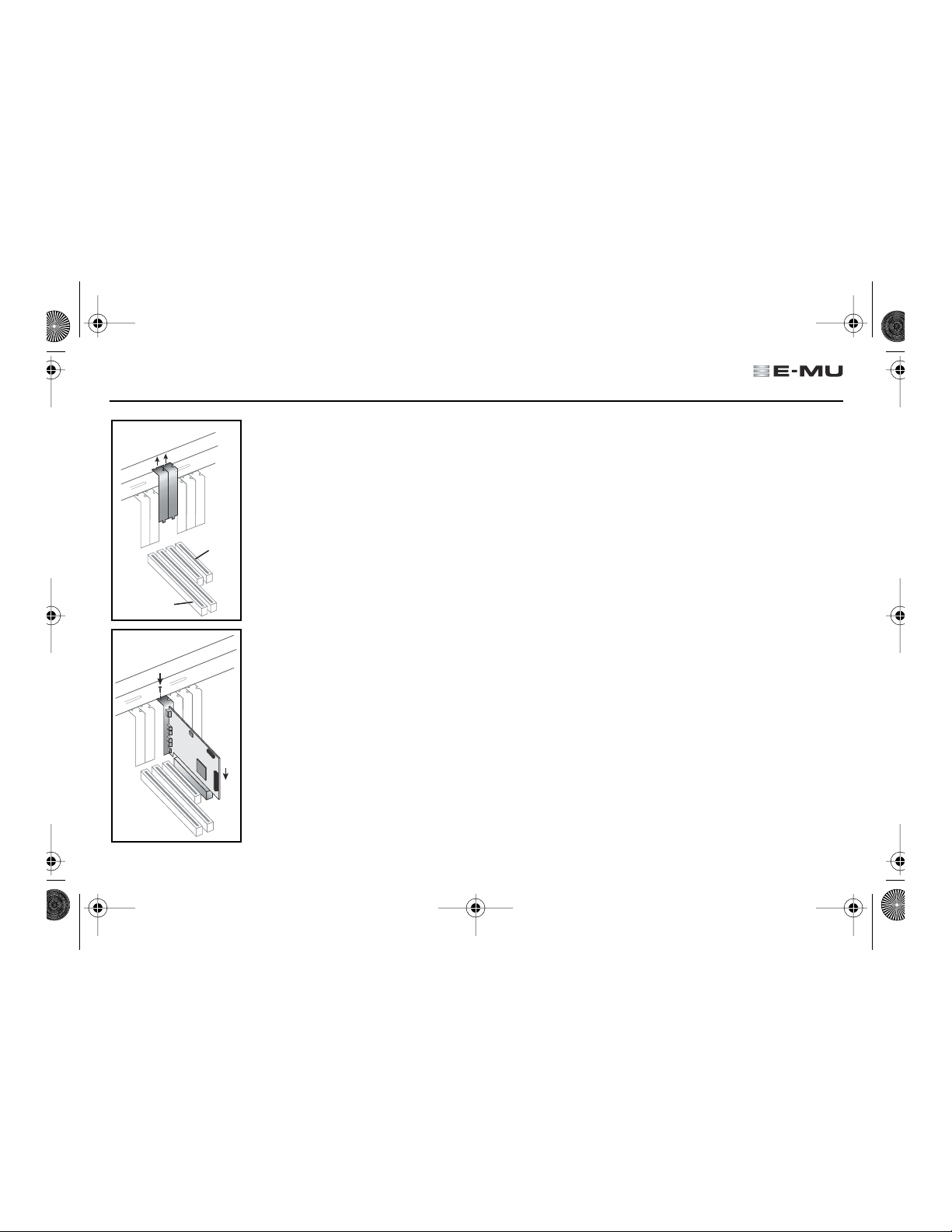
Metal
brackets
ISA slots
PCI slots
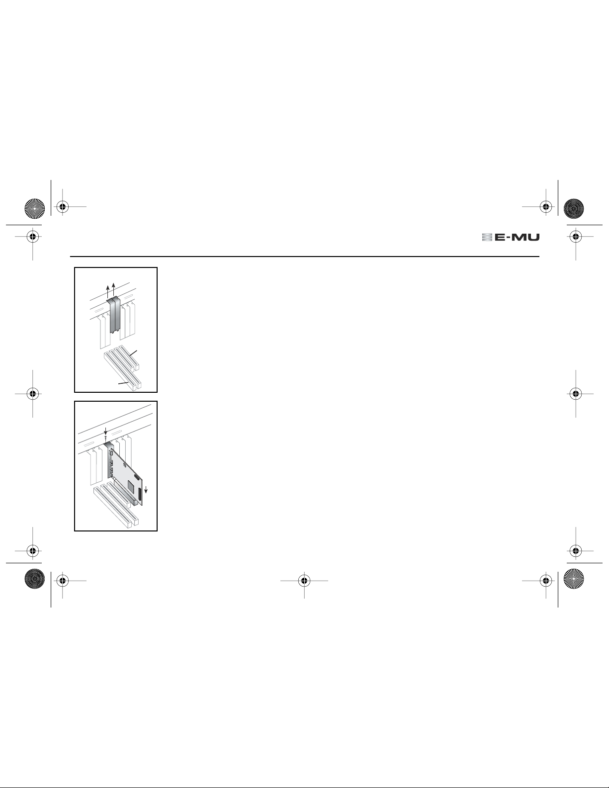
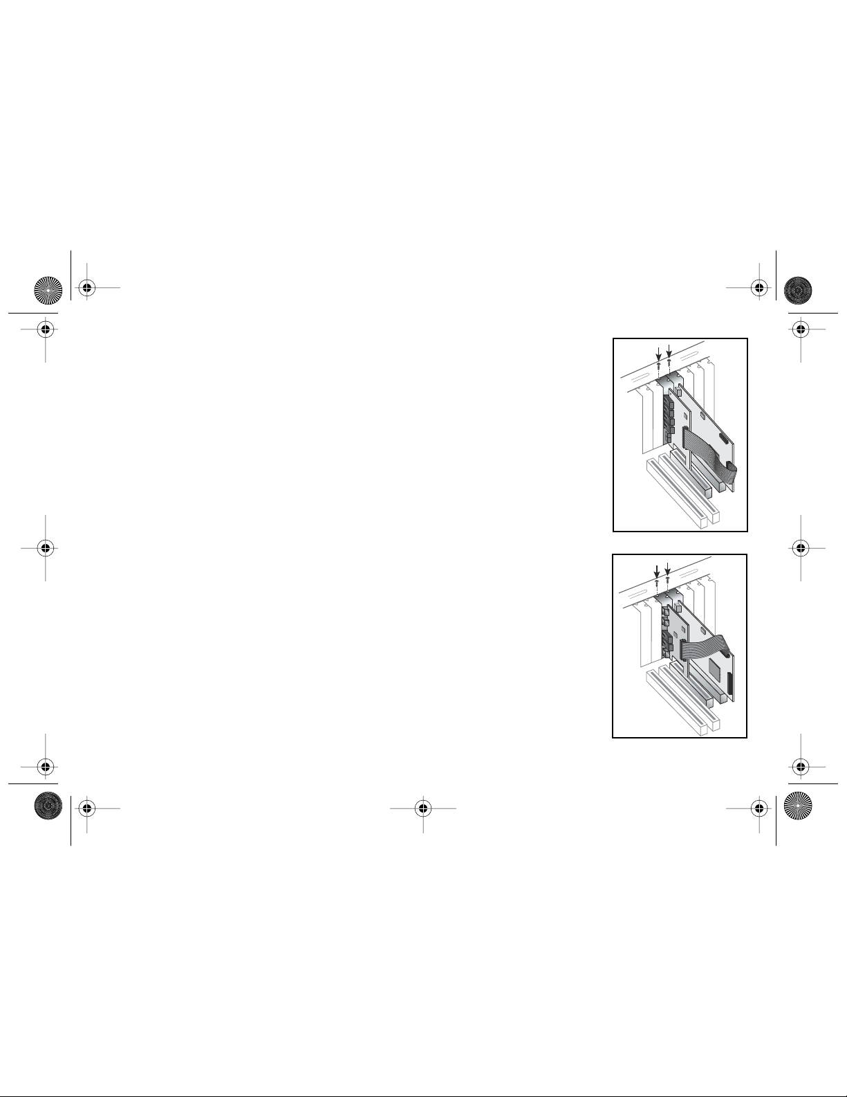
Step 1: Prepare your computer
1. Turn off your computer and all peripheral devices.
2. Touch a metal plate on your computer to ground yourself and to discharge any static
electricity, and then unplug the power cord from the wall outlet.
3. Remove the computer cover.
4. Remove the metal bracket from one PCI slot. If you have the E-MU 1212
installing the Sync Daughter Card you’ll need to remove the bracket from two PCI slots.
See the figure at left.
m
system or are
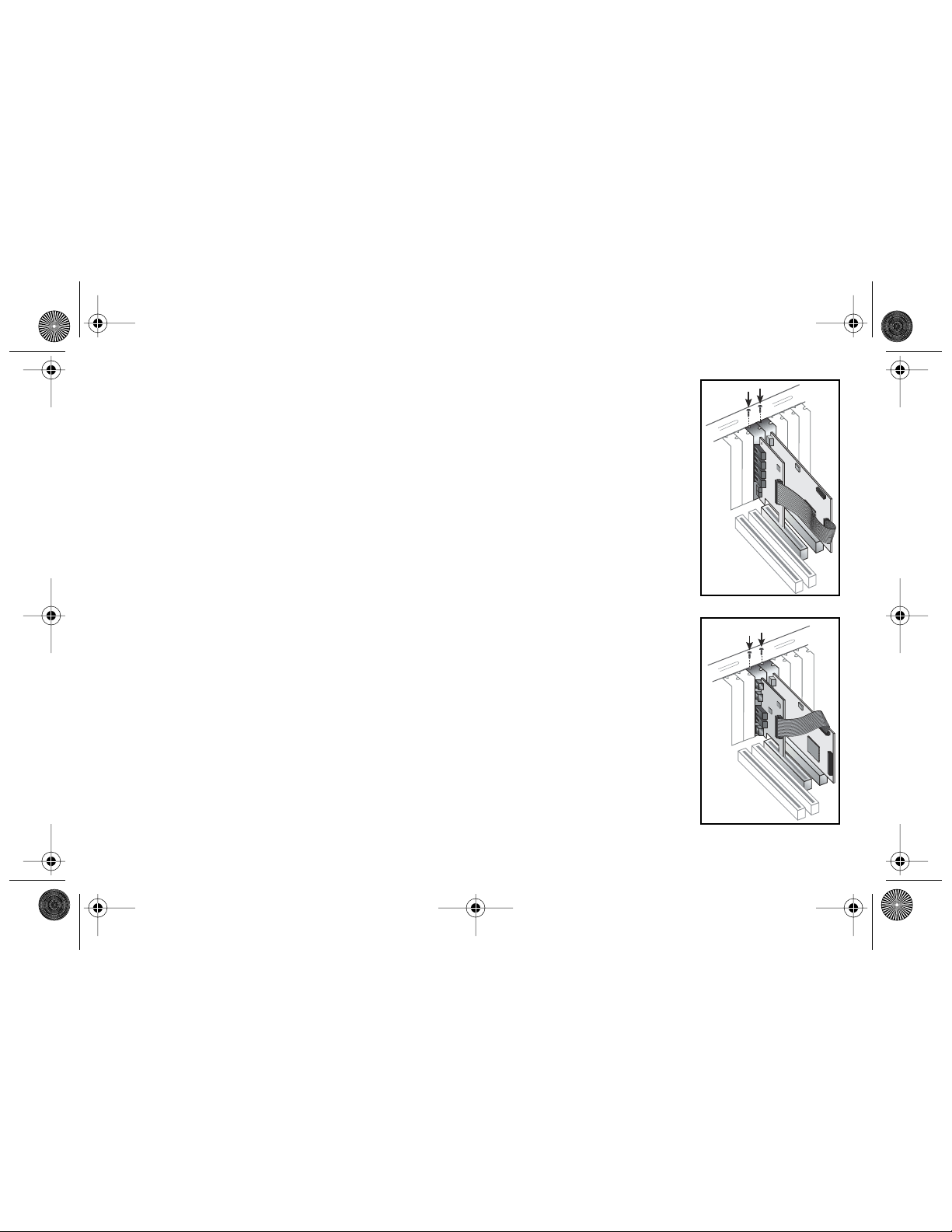
Step 2: Install the E-MU 1010 PCI card
1. Align the E-MU 1010 PCI card with the slot and press gently but firmly down into the slot
as shown in the figure opposite.
2. Do not force the E-MU 1010 card into the slot. Make sure that the gold finger connector
of the card is aligned with the PCI bus connector on the motherboard before you insert
the card into the PCI slot. If it doesn’t fit properly, gently remove it and try again.
3. Secure the card to the slot using a screw (if necessary).
Quick Start Guide - Getting Started - 3
Page 4

EMU QS(En).fm Page 4 Thursday, October 26, 2006 11:09 AM
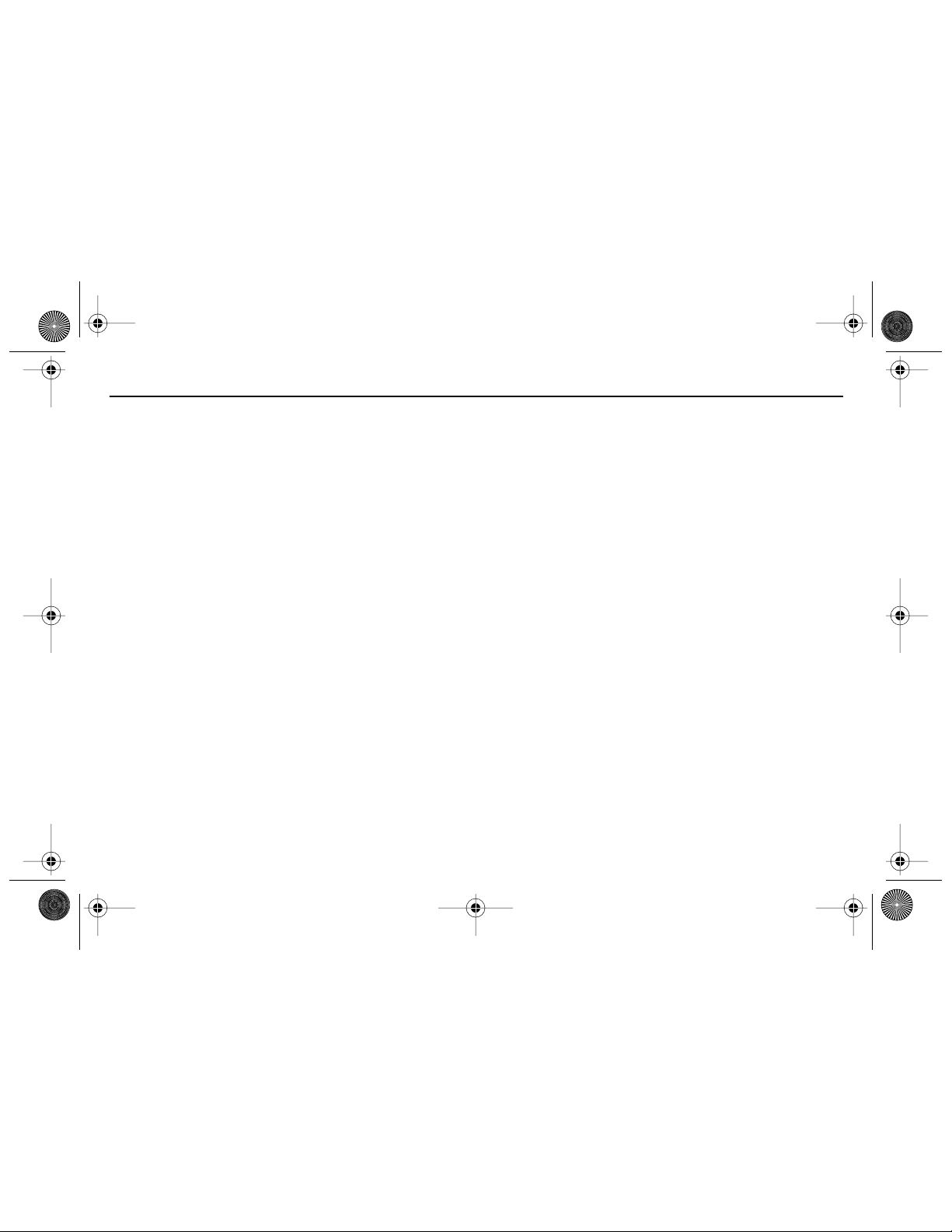
Step 3: 1212M Owners - Install 0202 I/O Daughter Card
Note: This step is for E-MU 1212M owners only. 1616/1616M owners, go on to Step 5
1. Connect the ribbon cable provided with the kit between the E-MU 1010 car d and the
I/O Daughter card as shown in the figure at right. The cable is keyed so it cannot be
incorrectly inserted. Seat the connector firmly in the socket and arrange the cable
neatly.
2. Secure the E-MU 0202 I/O Daughter card into the slot next to the E-MU 1010 card,
using a second screw (if necessary).
3. Replace the cover to your computer.
4. Plug the power cord and your peripheral devices into your computer and turn on
your computer.
5. Go to Section 3 - Software Installation on page 6.
Note: Step 4 is for owners of the optional Sync Card only.
Step 4: Sync Card Owners - Install Sync Daughter Card
1. Connect the ribbon cable provided with the kit between the E-MU 1010 car d and the
Sync Daughter card as shown in the figure at right. The cable is keyed so it cannot be
incorrectly inserted. Seat the connector firmly in the socket and arrange the cable
neatly.
2. Secure the E-MU Sync Daughter car d into the slot next to the E-MU 1010 card, using
a second screw (if necessary).
3. Replace the cover to your computer.
4. Plug the power cord and your peripheral devices into your computer and turn on
your computer.
5. Go to Section 3 - Software Installation on page 6.
4 - E-MU PCI Digital Audio System
0202 I/O Daughter Card
Optional Sync Daughter Card
Page 5
EMU QS(En).fm Page 5 Thursday, October 26, 2006 11:09 AM
Step 5: Connecting the MicroDock to the E-MU 1010 Card
Connect the supplied network-type cable from the RJ-45 jack on the E-MU 1010 PCI card labeled “EDI” to the matching
connector labeled “EDI” on the MicroDock. The cable type is a standard CA T 5e network cable which is specially shielded to
prevent RF emissions. Contact E-MU Systems if you need a replacement cable.
CAUTION: Do not connect the supplied CAT 5e cable to the Ethernet or network connector on your computer. Doing
so may result in permanent damage to either your computer, the E-MU 1010 or both.
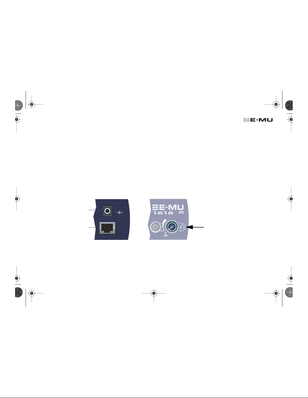
Supplying Power to the MicroDock
The MicroDock is powered from the supplied +48VDC Adapter. Connect the Adapter to the jack marked +48VDC on the
back panel of the MicroDock. Turn the MicroDock on by turning the Headphone Volume control up.
48
+48V DC Adapter
1010 PCI Card
VDC
+
-
The Headphone
EDI
Volume Control is
also the Power Switch.
Quick Start Guide - Getting Started - 5
Page 6
EMU QS(En).fm Page 6 Thursday, October 26, 2006 11:09 AM
3 - Software Installation
Installing and Uninstalling the E-MU 1010 Drivers and Applications
The first time you restart your PC after installing the 1010 PCI card, you need to install the Patchmix DSP software and 1010 drivers.
Windows XP, Windows 2000, x64
1. After you have installed your audio card, turn on your computer. Windows automatically detects your audio card
and searches for device drivers.
2. When prompted for the audio drivers, click the Cancel button.
3. Insert the E-MU software Installation CD into your CD-ROM drive.
If Windows AutoPlay mode is enabled for your CD-ROM drive, the CD starts running automatically. If not, from
your Windows desktop, click Start -> Run and type d:setup.exe (replace d:\ with the drive letter of your CD-ROM
drive). You can also simply open the CD and double-click Setup.exe .
4. The installation splash screen appears. Follow the instructions on the screen to complete the installation.
5. Choose “Continue Anyway” when you encounter the “Windows Logo Testing” warning screen.
6. When prompted, restart your computer.
Uninstalling all Audio Drivers and Applications
At times you may need to uninstall or reinstall some or all of the audio card's applications and device drivers to correct
problems, change configurations, or upgrade outdated drivers or applications. Before you begin, close all audio card
applications. Applications still running during the uninstallation will not be removed.
1. Click Start -> Settings -> Control Panel .
2. Double-click the Add/Remove Programs icon.
3. Click the Install/Uninstall tab (or Change or Remove Programs button).
4. Select the E-MU 1010 PCI card entry, or the application entry and then click the Add/Remove
(or Change/Remove ) button.
5. In the InstallShield Wizard dialog box, select the Remove option.
6. Click the Yes button.
7. Restart your computer when prompted.
8. You may now re-install existing or updated E-MU 1010 PCI card device drivers or applications.
6 - E-MU PCI Digital Audio System
(The software is not compatible with other versions of Windows.)
Page 7

EMU QS(En).fm Page 7 Thursday, October 26, 2006 11:09 AM
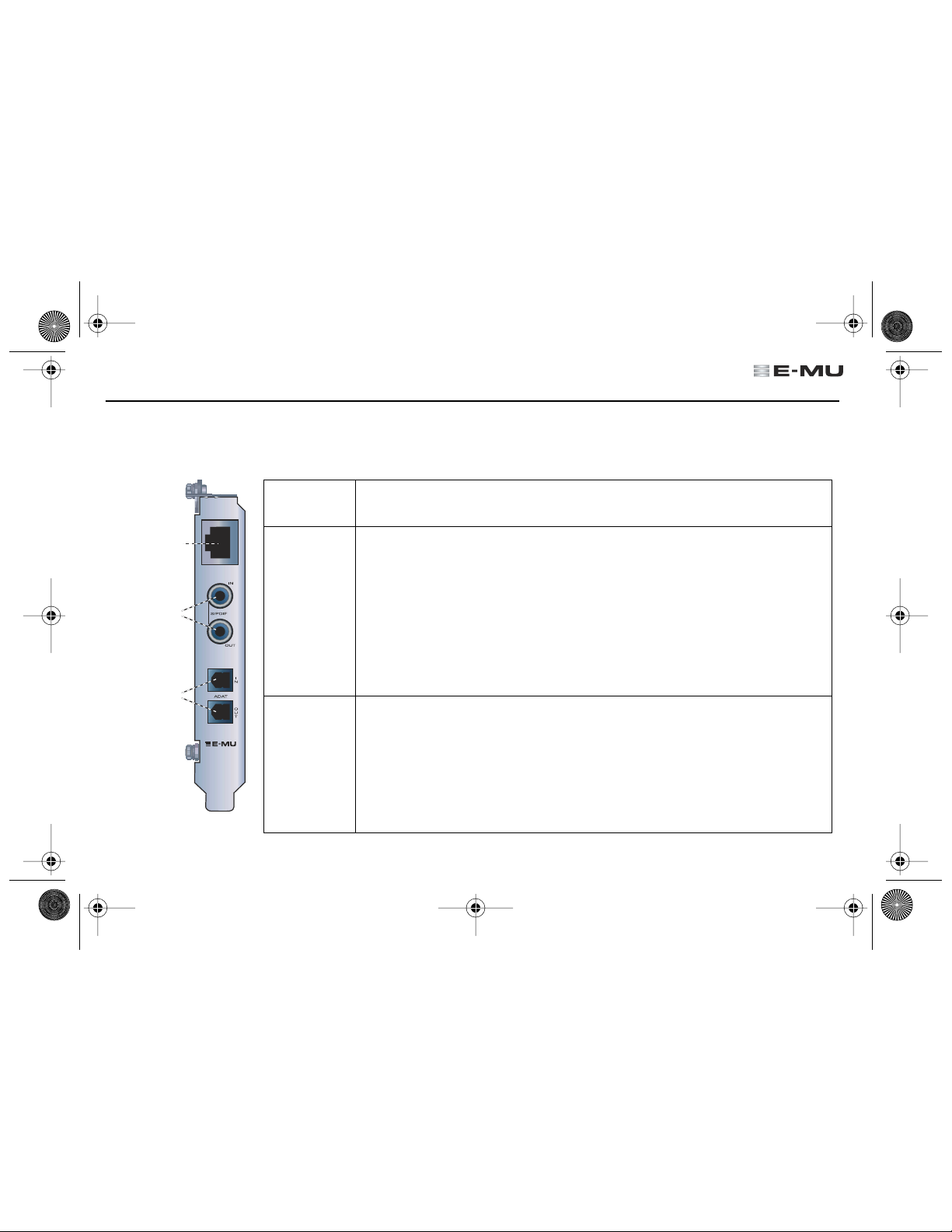
4 - E-MU 1010 PCI Card & Interface
The E-MU 1010 PCI card is the heart of the system and contains E-MU’s powerful E-DSP chip. The powerful hardware DSP
on this card leaves more power free on your CPU for additional software plug-ins and other tasks.
Connections
Connects to
Audio Dock
via EDI Cable
S/PDIF
In/Out
ADAT
or S/PDIF
Optical
In/Out
EDI
EDI
Connector
S/PDIF
Digital
Audio
Input &
Output
®
ADAT
Optical
Digital
Input &
Output
Connects to the MicroDock using EDI (E-MU Digital Interface) cable. This cable provides
a two-way data link between the E-MU 1010 and the MicroDock.
Each RCA phono jack carries two channels of digital audio. S/PDIF digital I/O can be used
for the reception and/or transmission of digital data from external digital devices such as
a DAT machine, an external analog-to-digital converter or an external signal processor
equipped with digital inputs and outputs. The embedded clock contained in the input
data stream can be used as a clock source for the 1010.
The S/PDIF out can be configured in either Professional or Consumer mode, always with
24-bits of resolution.
Important: S/PDIF I/O is disabled on the 1010 PCI when the MicroDock is connected.
The ADAT optical connectors transmit and receive 8 channels of 24-bit audio using the
ADAT type 1 & 2 formats (at 44.1kHz or 48kHz). The embedded clock contained in the
input data stream can be used as a clock sour ce for the 1010. The ADA T optical ports can
also be switched to carry optical S/PDIF.
ADAT can also be transmitted and received at 96kHz or 192kHz using the S/MUX
standard which encodes the extra data onto multiple channels.
Important: ADAT I/O is disabled on the 1010 PCI when the MicroDock is connected.
Quick Start Guide - Getting Started - 7
Page 8
EMU QS(En).fm Page 8 Thursday, October 26, 2006 11:09 AM
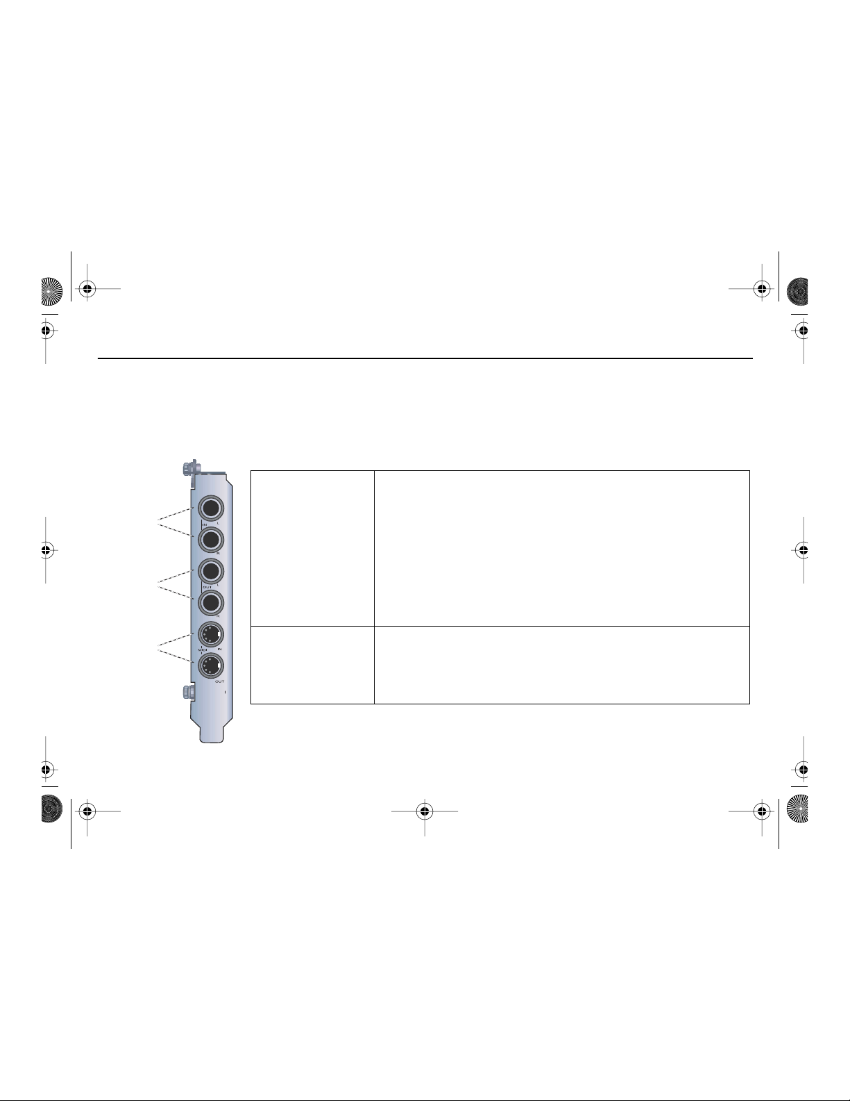
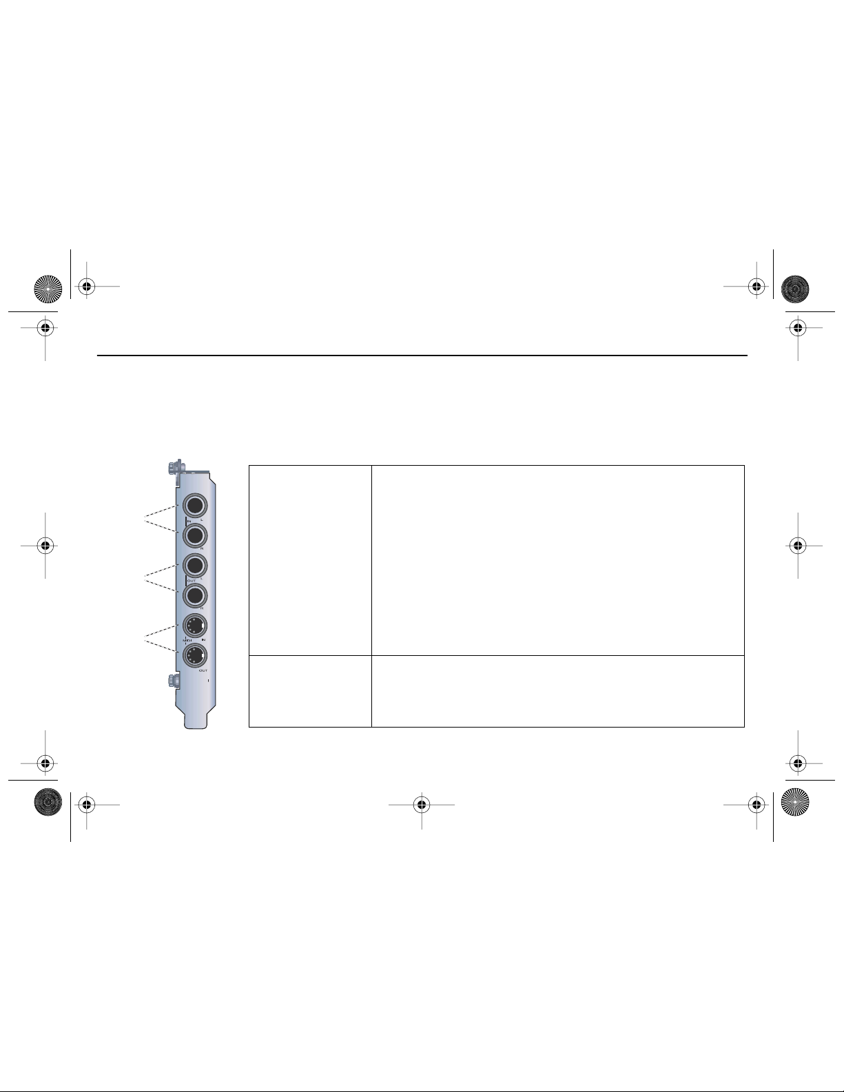
5 - The E-MU 0202 I/O Daughter Card
The I/O daughter card provides one pair of 24-bit balanced analog inputs and one pair of 24-bit balanced analog outputs,
plus MIDI in and out. The I/O daughter card provides the analog inputs, outputs, and MIDI interface for E-MU digital audio
systems which don’t include the MicroDock. The I/O Daughter card takes up one extra space on the back panel of your
computer, and connects to the E-MU 1010 PCI card via an internal 40-pin ribbon cable.
Connections
Left / Right
Line Inputs
Analog Inputs
and Outputs
Left / Right
Line Outputs
MIDI
In/Out
MIDI In/Out
8 - E-MU PCI Digital Audio System
The inputs can be connected to any line level stereo signal from a
keyboard, CD-player, cassette deck, etc. (The analog inputs are assigned to
mixer strips in the PatchMix DSP mixer application.)
The outputs can feed any line level input such as a mixing board, the
auxiliary input on your stereo, or a set of powered speakers.
Either TRS balanced or TS unbalanced cables can be used. Balanced cables
provide better noise immunity and +6dB higher signal level. The output
line level can be set to accommodate the consumer -10dBV standard, or
the pro audio +4 dBu standard in the I/O screen of the Session Settings
dialog box.
The MIDI input and output port can be assigned in your specific MIDI
application. Connect the MIDI adapter cable that came with your I/O
Daughter card to the mini-DIN connectors on the card. The supplied MIDI
adapter cables convert the mini-DIN to standard DIN connectors used on
most keyboards and synthesizers.
Page 9
table
EMU QS(En).fm Page 9 Thursday, October 26, 2006 11:09 AM
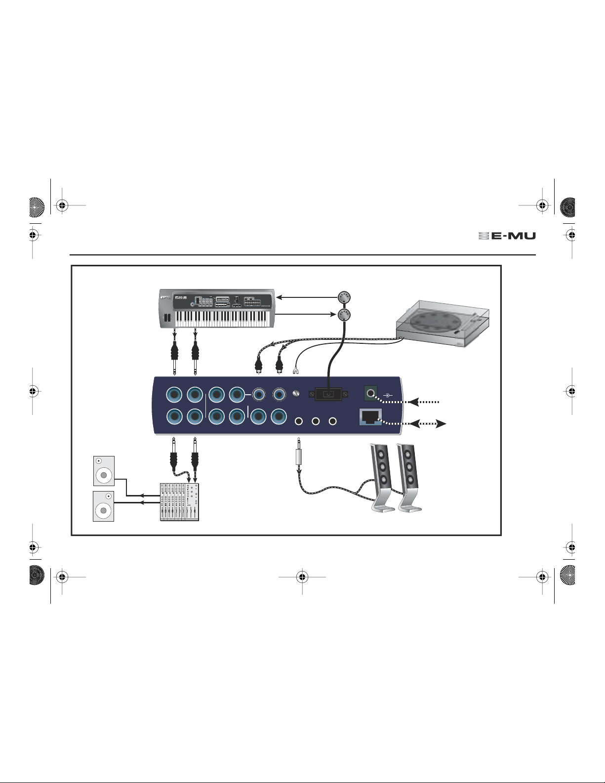
6 - MicroDock Connections
Basic
Connections
Synthesizer
Monitors
Audio
from
Audio
to
MIDI Synthesizer
MIDI In
Out
Turn
MIDI 1
MIDI Out
In
**
Phono
2L
2R
1L
In
Out
1L
2L
1R
1R
2L
2R
2R
3R
3L
Mixer
&
Speakers
* Note: Line Inputs 2L/2R and Phono 2L/2R cannot be used at the same time.
Gnd
1
Speakers to
MIDI Cable
Out
2
Connect
Desktop
1/8" jacks
e
t
S
48
VDC
+
-
3
EDI
AC Adapter
1010 PCI
Card
Powered
Desktop
Speakers
e
r
o
Quick Start Guide - Getting Started - 9
Page 10

EMU QS(En).fm Page 10 Thursday, October 26, 2006 11:09 AM
Front Panel
Analog Connections
Use the 3-pin XLR jack
for Low Impedance
microphones.
Mic
Line
Mic
A
Line -
Mic -
Clip
-3
-6
SL
-12
-20
-15
0
Use the center
Phone Jack for
High Impedance
instruments such
Instrument
as electric guitar
or bass.
10 - E-MU PCI Digital Audio System
Line
B
+50
+65
Mic
Clip
-3
-6
SL
-12
-20
-15
0
+50
+65
S/PDIF
48V
Out
In
Off
On/Off
& Phone Volume
Stereo
Headphones
Page 11
EMU QS(En).fm Page 11 Thursday, October 26, 2006 11:09 AM
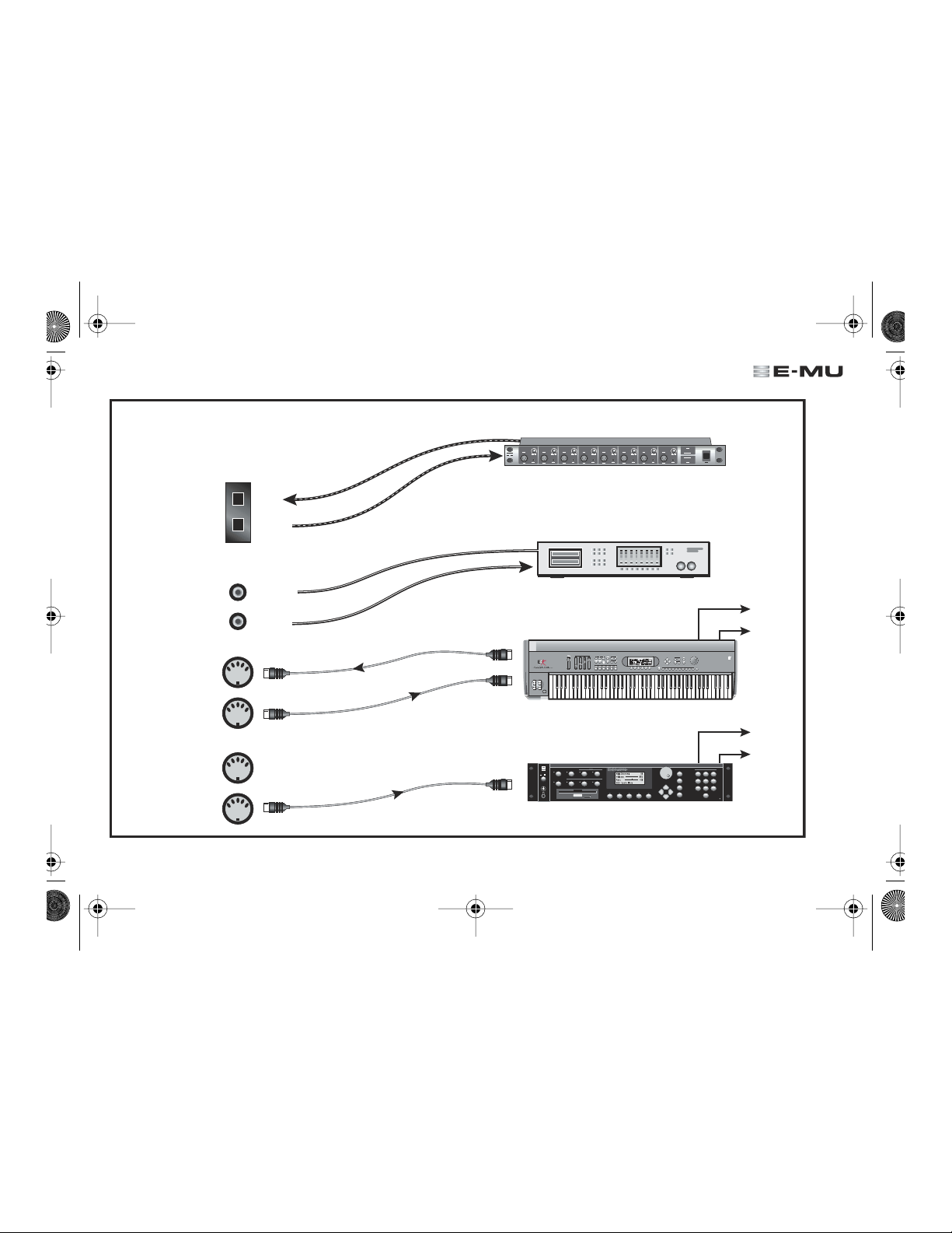
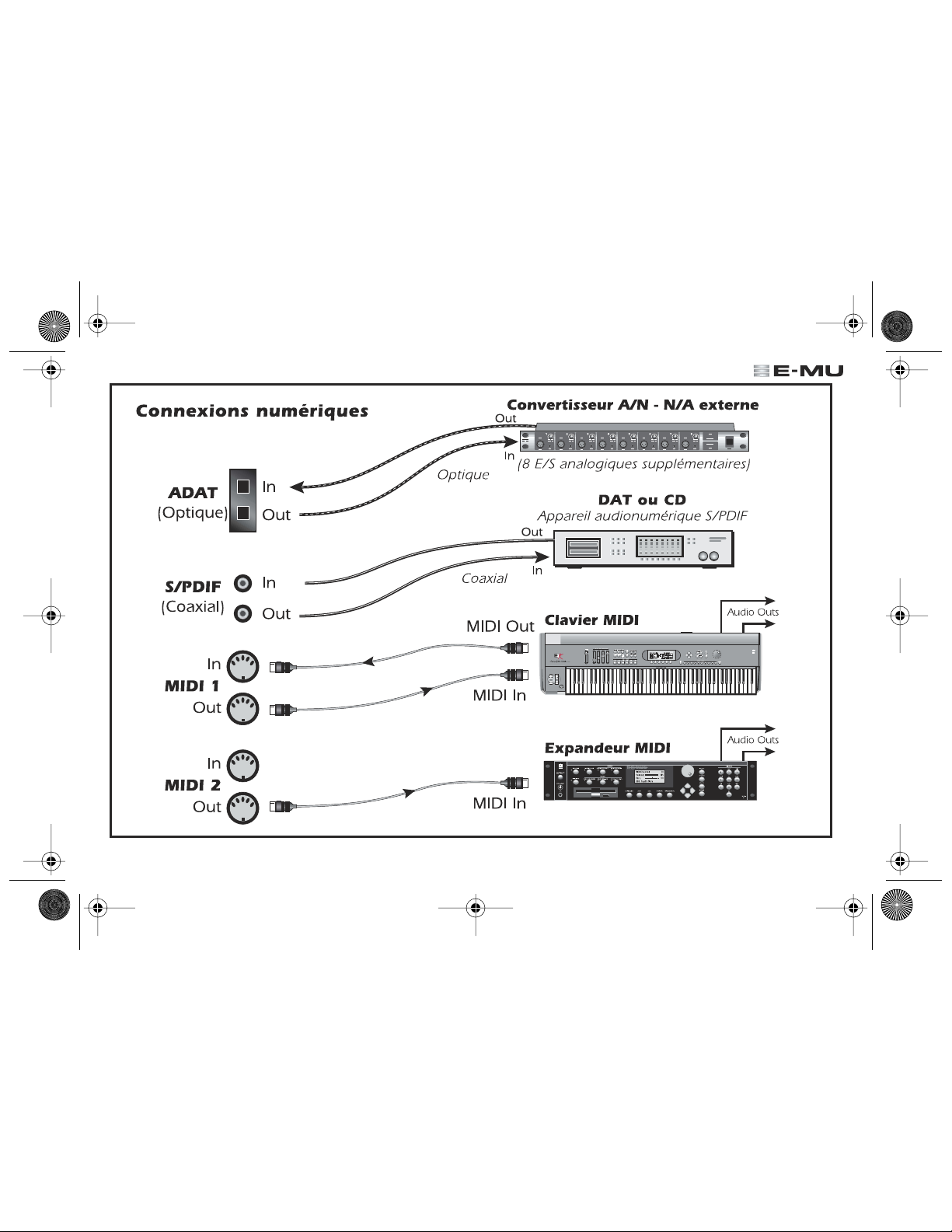
Digital Connections
ADAT
(Optical)
S/PDIF
(Coax)
In
MIDI 1
Out
In
MIDI 2
Out
In
Out
In
Out
Optical
Coaxial
MIDI Out
MIDI In
MIDI In
External A/D - D/A Converter
Out
1 2 3 4 5 6 7 8
In
(8 more analog inputs & outputs)
DAT or CD
Digital Audio Device with S/PDIF
Out
In
MIDI Keyboard
REAL TIME CONTROLLERS
ASSIGNABLE KEYS
PRESET
SAMPLE
SEQUENCER
EMULATOR
MIDI Sound Module
SAMPLE
MASTER/GLOBAL
TRANSPOSE DIGITAL PROCESSINGSAMPLE MANAGEMENT
I
O
PRESET
MULTIMODE
PRESET MANAGEMENT DYNAMIC PROCESINGPRESET DEFINITION
VOLUME
DRIVE SELECT LOAD SAVE AUDITION TRIGGER MODE
Quick Start Guide - Getting Started - 11
LEVEL
EXIT
ENTER
PAGE
PRESET SELECT
INC/YES
DEC/NO
ENTER
ESCAPE
Audio Outs
RETURN
0.987654321
Audio Outs
TRIGGERS
ABC
DEF
123
JKL
MNO
GHI
456
TUV
WXY
PRS
789
QZ
0
MIDI
Page 12

EMU QS(En).fm Page 12 Thursday, October 26, 2006 11:09 AM
7 - MicroDock & MicroDock M
The MicroDock connects to the E-MU 1010 PCI card via the EDI cable. The fr ont of the MicroDock provides 2 balanced mic/
line preamp inputs, 8 channels of ADAT digital input/output, stereo S/PDIF digital input/output, and a stereo headphone
output with volume control/power switch.
Front Panel Connections
1/4" Line
Level Input
-15dB to +50dB Gain
Line
A
Line -
Mic -
Mic
Clip
SL
-10
+20
Insert XLR Plug
for Mic Level
0dB to +65dB Gain
12 - E-MU PCI Digital Audio System
Clip
Soft
Limit
B
-3
-6
-12
-20
+25
+55
Input Gain
Signal
Meters
Line
Mic
Controls
Phantom
On/Off
Clip
SL
-12
-20
-10
+20
Power
-3
-6
+25
+55
S/PDIF
Coaxial I/O
48V
S/PDIF
In
ADAT
Optical I/O
Headphone Volume
/ Power Switch
Out
Off
Headphone
Output
Page 13

EMU QS(En).fm Page 13 Thursday, October 26, 2006 11:09 AM
The front panel mono Mic/Line inputs A & B can be used as balanced microphone inputs, hi-Z
guitar pickup inputs, or balanced line level inputs. The Neutrik combination jack accepts
Preamp Section
microphones using a standard XLR connector or line level/hi-Z inputs using a 1/4 inch TRS phone
plug.
Warning: Some microphones cannot tolerate phantom power and may be damaged. Check the
microphone’s specifications and requirements before using phantom power.
S/PDIF Digital
Audio Input &
Output
®
ADAT
Optical
Digital Input &
Output
Headphone
Output &
Volume Control
Each RCA phono jack carries two channels of digital audio. S/PDIF digital I/O can be used for the
reception and/or transmission of digital data fr om external digital devices such as a DA T machine, an
external analog-to-digital converter or an external signal processor equipped with digital inputs and
outputs. The word clock contained in the input data stream can be used as a clock source.
The S/PDIF output can be configured in either Professional or Consumer mode (always 24-bit
resolution). The S/PDIF input/outputs support all the PatchMix DSP sample rates: 44.1kHz, 48kHz,
88.2kHz, 96kHz, 176.4kHz & 192kHz.
• The ADAT optical connectors transmit and receive 8 channels of 24-bit audio using the ADAT
type 1 & 2 formats (at 44.1kHz or 48kHz).
• The word clock contained in the input data stream can be used as a clock source.
• The ADAT optical ports can also be switched to carry optical S/PDIF.
• ADAT can also be transmitted and received at 88, 96, 176, or 192kHz using the S/MUX standard.
S/MUX provides 4 audio channels at 88.2/96 and 2 audio channels at the 176/192 sample rates.
The headphone output drives standard stereo headphones and the adjacent volume contr ol sets
the listening level. This output is permanently connected to the Monitor Output in PatchMix DSP.
The headphone output uses a high-current version of the high-quality output amplifiers used on
the other channels. For this reason it has a very clean signal that can be used as another stereo
output if you need it.
Quick Start Guide - Getting Started - 13
Page 14
t
EMU QS(En).fm Page 14 Thursday, October 26, 2006 11:09 AM
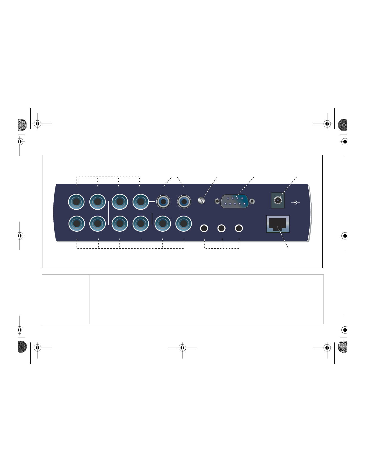
Rear Panel Connections
4 Balanced Line Level Inputs
(configured as 2 stereo pairs)
2L
2L
Out
1L
In
1L
1R
1R
(configured as 3 stereo pairs)
Four balanced 24-bit, line-level, analog inputs are provided (Stereo 1-2). These can be used to
input any line level signal such as a keyboard, CD-player, cassette deck, etc. (The analog inputs are
Line Level
Analog Inputs
assigned to mixer strips in the PatchMix DSP mixer application.) Input line level can be set to
accommodate the consumer -10dBV standard, or the pro audio +4 dBu standar d in the I/O screen
of the Session Settings dialog box.
Either TRS balanced or TS unbalanced cables can be used. Balanced cables provide better noise
immunity and +6dB higher signal level, but standard mono instrument cables also work well.
14 - E-MU PCI Digital Audio System
Turntable Inputs
(tied to line input 2)
2R
2R
2L
3L
Phono
Turntable
Ground
2R
Gnd
1
3R
Alternate Outputs6 Balanced Line Level Outputs
(same as outputs 1-3)
MIDI Cable
Out
2
MIDI Port
Connector
3
48 Volt DC
Power Inpu
48
VDC
+
-
EDI
Connect to
1010 PCI Card
Page 15
EMU QS(En).fm Page 15 Thursday, October 26, 2006 11:09 AM
Six balanced 24-bit, line-level, analog outputs are provided (Stereo 1-3). Output pair 1 is
designated as the Monitor Output and is normally fed by the monitor output of the PatchMix DSP
mixer application. All the analog outputs can be freely assigned in the mixer application.
Line Level
Analog
Outputs
Special anti-pop circuitry mutes the analog outputs when power is turned on or off.
Like the analog line inputs, either TRS balanced or TS unbalanced cables can be used.
Balanced cables provide better noise immunity and +6dB higher signal level, but standard mono
instrument cables also work well.
The output line level can be set to accommodate the consumer -10 dBV standard, or the pro audio
+4 dBu standard in the I/O screen of the Session Settings dialog box.
Turntable
Inputs &
Ground Lug
MIDI 1& 2
In/Out
Alternate
Outputs
EDI Connector
The RCA turntable inputs feed an RIAA equalized phono preamp designed to accept moving
magnet type phono cartridges. The turntable inputs share line level inputs 2L and 2R. Inserting a
plug into Line Input 2 disconnects the phono preamp from that channel. Connect the gr ound lead
from your turntable to the turntable ground lug to prevent hum.
Attach the supplied MIDI Breakout cable to the MIDI Port connector on the rear of the Micr oDock.
MIDI input and output ports allow you to interface any type of MIDI equipment such as keyboards,
effect units, drum or guitar controllers. The MIDI drivers were installed when you installed your
Patchmix DSP software and the MIDI ports will appear in your system control panel under “Sounds
and Audio Devices”.
These stereo mini-phone (3.5mm) jacks duplicate the line level outputs 1-3. These line level
outputs are designed for easy interface to powered computer speakers.
Connects the MicroDock to the E-MU 1010 PCI card using CA T 5e type computer cable. The cable
supplied with the MicroDock is specially shielded to prevent unwanted RF emissions.
Quick Start Guide - Getting Started - 15
Page 16

EMU QS(En).fm Page 16 Thursday, October 26, 2006 11:09 AM
8 - The E-MU Sync Daughter Card (optional)
The optional Sync Daughter card provides Word Clock in and out, SMPTE (LTC) in and out and an additional MIDI output
for transmitting MIDI Time Code (MTC). MTC is a special rendering of SMPTE that can be transmitted over MIDI cables.
Note: When the Sync Card is installed, MIDI 2 on the MicroDock is disabled. (MTC is using the MIDI port.)
Word Clock is a standard means of synchronizing two or more pieces of digital equipment at the system sample rate
(44.1kHz, 48kHz, 96kHz, or 192kHz). To avoid data corruption, digital equipment MUST be synchronized to each other.
Recording equipment can also be synchronized using SMPTE or MTC sync so that two audio recorders or an audio and
video recorder can lock together as a single machine. For more information, please refer to your Owner’s Manual (on CD).
Connections
Word Clock In: Receives word clock (sample clock) from another digital device such
Word Clock
Inputs and
Outputs
SMPTE In/Out
MTC Out
as a digital video deck, digital recorder or digital mixer.
Word Clock Out: Sends word clock (sample clock) to another digital recorder. Word
clock is always output, whether it is generated by the internal clock or passed
through from the word clock input.
The SMPTE Input converts incoming SMPTE longitudinal time code (LTC) to MIDI T ime
Code (MTC) and passes this information to the host computer to be used by a
sequencer or audio recorder application. When your computer application is the
“Master”, MTC generated by the computer application is converted into SMPTE and
sent out to another SMPTE device such as another audio recorder to synchronize it
with the sequencer.
This output transmits MIDI Time Code to another computer or audio recorder. The
source of the MTC can be from the sequencer or SMPTE in.
16 - E-MU PCI Digital Audio System
Page 17

EMU QS(En).fm Page 17 Thursday, October 26, 2006 11:09 AM
Copyright
Information in this document is subject to change without notice and does not repr esent a commitment on the part
of E-MU Systems, Inc. No part of this manual may be repr oduced or transmitted in any form or by any means, electronic
or mechanical, including photocopying and recording, for any purpose without the written permission of E-MU Systems,
Inc. The software described in this document is furnished under a license agr eement and may be used or copied only
in accordance with the terms of the license agr eement. It is against the law to copy the software on any other medium
except as specifically allowed in the license agreement. The licensee may make one copy of the softwar e for backup
purposes only.
E-MU is a registered trademark of E-MU Systems, Inc. in the United States and/or other countries.
Copyright © 2006 by E-MU Systems, Inc. All rights reserved.
Version 1.82,
April 2006
The use of the WEEE symbol indicates that this product may not be
treated as household waste. By ensuring this product is disposed of
correctly, you will help protect the environment. For more detailed
information about the recycling of this product, please contact your
local authority, your household waste disposal service provider or
the shop where you purchased the product.
Quick Start Guide - Getting Started - 17
Page 18
EMU QS(En).fm Page 18 Thursday, October 26, 2006 11:09 AM
18 - E-MU PCI Digital Audio System
Page 19
EMU GS(Fr).fm Page 19 Thursday, October 26, 2006 1:15 PM
1 - Introduction
Merci d’avoir acheté le système audio numérique E-MU 1212M, E-MU 1616 ou E-MU 1616M. Nous avons conçu ce
système audio numérique E-MU afin qu’il soit logique et intuitif et qu’il vous offre surtout une qualité sonore irréprochable.
Les trois systèmes audio offre une qualité studio professionnel, un enregistrement et une lecture multicanaux 24 bits/
192 kHz pour un prix incroyablement réduit.
Configuration requise
•Processeur Intel
• Carte mère et jeu de puces Intel, AMD ou 100 % compatible.
• Windows XP (SP2), Windows 2000 (SP4), or Windows XP x64
• 256 Mo de RAM
• 900 Mo d’espace disque disponible pour une installation complète.
• Emplacement disponible compatible PCI 2.1 (deux emplacements sont nécessaires pour E-MU 1212M et 1616M)
•Vidéo XVGA (1024 x 768)
• Lecteur de CD-ROM/CD-RW et DVD-ROM nécessaire pour l’installation du logiciel.
• Casque ou haut-parleurs amplifiés.
D’autres applications peuvent avoir des exigences plus élevées ou nécessiter un microphone.
®
ou AMD
®
à 1 GHz ou plus rapide.
Contenu du coffret
E-MU 1212
• Carte PCI E-MU 1010
• Carte fille E/S E-MU 0202
• Câble en nappe pour carte fille E/S
• (2) câbles mini MIDI
• CD d’installation des logiciels/Drivers
Digital Audio Systems
• CD-ROM d’outils de production
• Guide de démarrage rapide
m
PCI E-MU 1616 PCI E-MU 1616
• Carte PCI E-MU 1010
•MicroDock
• Câble EDI (E-MU Digital Interface,
interface numérique E-MU)
• Câble de conversion
• Adapteur de +48VDC
• CD d’installation des logiciels/Drivers
Digital Audio Systems
• CD-ROM d’outils de production
• Guide de démarrage rapide
m
PCI
• Carte PCI E-MU 1010
•MicroDock M
• Câble EDI (E-MU Digital Interface, interface
numérique E-MU)
• Câble de conversion
•
Adapteur de +48VDC
• CD d’installation des logiciels/Drivers Digital
Audio Systems
• CD-ROM d’outils de production
• Guide de démarrage rapide
Guide de mise en œuvre - Prise en main - 19
Page 20

EMU GS(Fr).fm Page 20 Thursday, October 26, 2006 1:15 PM
Consignes de sécurité
Lors de l’installation de composants matériels, respectez les précautions générales ci-dessous pour éviter de vous blesser ou
d’endommager le matériel.
• Pour éviter d’endommager de manière irréversible votre matériel, vérifiez que toutes les connexions sont effectuées sur la
carte E-MU 1010 et sur MicroDock lorsque l’ordinateur hôte est hors tension.
l’ordinateur pour vous assurer que l’ordinateur n’est pas en mode veille.
• Assurez-vous que les composants de votre système ne subissent pas de dégâts liés à l’électricité statique. Les surfaces
internes de l’ordinateur, la carte PCI E-MU 1010 et les interfaces sont susceptibles de subir des décharges électrostatiques,
fréquemment appelées « statiques ». Les décharges électrostatiques peuvent endommager ou détruire les appareils
électroniques. Vous trouverez ci-dessous des procédures à suivre lors de la manipulation d’appareils électroniques qui vous
permettront de réduire le risque de dégâts électrostatiques.
• Evitez tout mouvement inutile. Evitez par exemple de traîner les pieds lorsque vous manipulez des appareils électroniques,
car les mouvements génèrent de l’électricité statique supplémentaire.
• Réduisez la manipulation de la carte PCI à un minimum. Conservez-la dans son emballage antistatique jusqu’à ce que vous
en ayez besoin. Transportez ou conservez la carte dans son emballage protecteur.
• Lorsque vous manipulez la carte PCI, évitez de toucher les broches. Essayez de manipuler la carte en la tenant par les
bords.
•Avant d’installer une carte PCI dans votre ordinateur, vous devez être relié à la terre. Utilisez un conducteur de terre pour
décharger votre organisme de tout excès de charge électr ostatique. Le conducteur de terre s’attache au poignet et à toute
surface métallique dépourvue de peinture de votre ordinateur.
Débranchez le câble d’alimentation de
Pour plus d’informations
Reportez-vous aux différents fichiers d’aide en ligne et au manuel de l’utilisateur (sur CD) pour obtenir des informations
détaillées sur le système audio E-MU et sur les différentes applications logicielles.
Après l'installation logicielle : Cliquez sur l'icône E-MU du menu déroulant des applications Windows et ouvrez
PatchMix DSP. Cliquez ensuite sur l'icône dans le coin supérieur droit pour ouvrir le mode d'emploi complet.
?
Assistance technique
Dans la mesure où le système audio numérique E-MU ne cesse de se développer, vous voudrez sûrement suivre les évolutions logicielles et les dernières options de votre système audio numérique E-MU. Vous trouverez toutes ces informations, et
bien d’autres encore, sur le site www.emu.com . Reportez-vous au manuel de l’utilisateur sur CD pour obtenir le numéro
de téléphone de l’assistance technique.
20 - Système audio numérique E-MU PCI
Page 21
EMU GS(Fr).fm Page 21 Thursday, October 26, 2006 1:15 PM
2 - Installation du matériel
Braquet metalliques
Ports PCI
Ports ISA
Etape 1 : Préparation de l’ordinateur
1. Mettez l’ordinateur et tous les périphériques hors tension.
2. Touchez une surface métallique de l’ordinateur pour vous mettre à la terre et vous
décharger de toute électricité statique, puis débranchez le cordon d’alimentation de la
prise murale.
3. Retirez le capot de l’ordinateur.
4. Retirez les support métallique de un emplacement PCI.
enlevez 2 appuis adjacents en métallique.
Voir la figure à gauche.
Si vous avez le système 1212M,
Etape 2 : Installation de la carte PCI E-MU 1010
1. Alignez la carte PCI E-MU 1010 avec l’emplacement et insérez-la dans l’emplacement en
appuyant doucement mais fermement, comme le montre la figure ci-contre.
2. Ne forcez pas pour insérer la carte E-MU 1010 dans l’emplacement. Vérifiez que le
connecteur à contacts dorés de la carte est aligné avec le connecteur du bus PCI sur la
carte mère avant d’insérer la carte dans l’emplacement PCI. Si la carte ne s’insère pas,
retirez-la doucement et réessayez.
3. Si nécessaire, fixez la carte à l’emplacement à l’aide d’une vis.
Guide de mise en œuvre - Prise en main - 21
Page 22
EMU GS(Fr).fm Page 22 Thursday, October 26, 2006 1:15 PM
Etape 3 : Installation de la carte fille E/S E-MU 0202
Remarque : Cette étape concerne uniquement les utilisateurs des système E-MU 1212M.
Autrement continuez à la Etape 5.
1. Connectez le câble en nappe fourni avec le kit entre la carte E-MU 1010 et la carte fille
E/S ou la carte fille de synchronisation comme illustré ci-dessous. Les câbles sont
verrouillés pour qu’ils ne soient pas insérés de manière incorr ecte. Enfoncez fermement
les connecteurs dans leurs socles et ordonnez les câbles.
2. Si nécessaire, fixez la carte de synchronisation E-MU ou la carte fille E/S E-MU dans
l’emplacement adjacent à la carte E-MU 1010 à l’aide d’une autre vis.
3. Replacez le capot de l’ordinateur.
4. Branchez le cordon d’alimentation et les périphériques de l’or dinateur et mettez-le sous
tension.
5. Allez au chapitre 3 Installation des logiciels.
Carte fille E/S E-MU 0202
Etape 4 : Installation de la carte fille de synchronisation
Connexion de MicroDock à la carte E-MU 1010
Connectez le câble de type réseau fourni de la prise RJ-45 située sur la carte PCI E-MU 1010 et
nommée « EDI » au connecteur correspondant nommé « EDI » sur MicroDock.
Le type de câble utilisé est un câble réseau CAT 5e standard qui est spécialement blindé pour
éviter les émissions de radiofréquences. Contactez l’assistance technique des systèmes E-MU si
vous avez besoin d’un câble de rechange.
ATTENTION : Ne connectez pas le câble CAT 5e fourni au connecteur réseau ou Ethernet
de votre ordinateur. Vous pourriez endommager de manière irréversible votre ordinateur et/
ou votre système E-MU 1010.
22 - Système audio numérique E-MU PCI
Carte fille de synchronisation
Page 23

EMU GS(Fr).fm Page 23 Thursday, October 26, 2006 1:15 PM
Etape 5 : Alimentation du MicroDock
Le MicroDock est alimenté par l’adaptateur secteur 48 Vcc fourni. Connectez l’adaptateur à l’embase +48VDC, à l’arrière du
MicroDock. Placez le MicroDock sous tension en tournant le bouton de volume du casque.
Adaptateur +48V
Carte 1010 PCI
Le bouton de volume
du casque sert à la mise
sous/hors tension.
Guide de mise en œuvre - Prise en main - 23
Page 24
EMU GS(Fr).fm Page 24 Thursday, October 26, 2006 1:15 PM
3 - Installation des logiciels
Installation et désinstallation des pilotes et des applications E-MU 1010
Lorsque vous redémarrez votre ordinateur pour la première fois après installation de la carte PCI E-MU 1010, vous devrez installer
le logiciel Patchmix DSP et les pilotes de la carte PCI E-MU 1010.
Windows XP, Windows x64, Windows
1. Après avoir installé votre carte son, allumez votre ordinateur. Windows détecte automatiquement votre carte son et
cherche les pilotes de périphérique.
2. Lorsque vous êtes invité à sélectionner les pilotes audio, cliquez sur le bouton
3. Insérez le CD d’installation des logiciels E-MU dans le lecteur de CD-ROM. Si le mode d'exécution automatique de
Windows est activé pour votre lecteur de CD-ROM, le CD démarre automatiquement.
2000
Démarrer -> Exécuter et tapez d:\setup.exe (remplacez d:\ par la lettre de votre lecteur de CD-ROM). Vous
pouvez ouvrir le CD et double-cliquer sur le fichier d:\setup.exe .
4. L’écran de lancement de l’installation apparaît. Suivez les instructions à l’écran pour terminer l’installation.
5. Sélectionnez « Continuer quand même » lorsque l’écran d’avertissement « Test permettant d’obtenir le logo Windows » apparaît.
6. Lorsque vous y êtes invité, redémarrez votre ordinateur.
Désinstallation de tous les pilotes audio et de toutes les applications
Vous pourrez être amené à désinstaller ou réinstaller tout ou partie des applications et les pilotes de périphérique de la
carte son afin de corriger des problèmes, de modifier des configurations ou de mettre à niveau des pilotes ou des applications obsolètes. Avant de commencer, fermez toutes les applications de carte son. Les applications en cours d’exécution lors
de la désinstallation ne seront pas supprimées.
1. Cliquez sur Démarrer -> Paramètres -> Panneau de configuration.
2. Cliquez deux fois sur l’icône
3. Cliquez sur l’onglet Installer/Désinstaller (ou sur le bouton Modifier/Supprimer des programmes).
4. Sélectionnez l’entrée correspondant à la carte PCI E-MU 1010 ou l’entrée de l’application puis cliquez sur
Ajout/Suppression (ou sur le bouton Modifier/Supprimer ).
5. Dans la boîte de dialogue
6. Cliquez sur le bouton
7. A l'invite, redémarrez votre ordinateur.
8. Vous pouvez désormais réinstaller les pilotes de périphérique ou les applications de la carte PCI 1010 existants ou mis à jour.
24 - Système audio numérique E-MU PCI
Ajout/Suppression de programmes.
InstallShield Wizard, sélectionnez l’option Supprimer .
Oui .
(Le logiciel n’est pas compatible avec d’autres versions de Windows.)
Annuler .
Sinon, dans le bureau, cliquez sur
Page 25
EMU GS(Fr).fm Page 25 Thursday, October 26, 2006 1:15 PM
4 - Carte et interface PCI E-MU 1010
La carte PCI E-MU 1010 est le cœur du système et contient la puissante puce E-DSP E-MU. La puissante puce DSP de cette
carte libère les ressources de votre unité centrale pour les modules externes supplémentaires et les autres tâches.
Connexions
Connection à
l'Audio Dock
Entrée et
Sortie
S/PDIF
Entrée et
Sortie ADAT
Optiques
EDI
Connecteur
EDI
Entrée et
sortie audio
numérique
S/PDIF
Entrée et
sortie
optique
®
ADAT
Se connecte à MicroDock à l’aide du câble EDI (E-MU Digital Interface). Ce câble fournit
une liaison de données double entre le système E-MU 1010 et MicroDock et fournit
également l’alimentation vers MicroDock.
Chaque prise phono RCA dispose de deux canaux pour le son numérique. L’entrée et la
sortie numérique S/PDIF peuvent êtr e utilisées pour la réception et/ou la transmission de
données numériques en provenance d’appar eils numériques tels qu’un appareil à bande
audionumérique, un convertisseur analogique/numérique externe ou un processeur de
signaux externes équipé d’entrées et de sorties numériques.
La sortie S/PDIF peut être configurée soit en mode Professionnel, soit en mode
Consommateur, dans une résolution de 24 bits dans les deux cas. L’entrée et la sortie
S/PDIF prennent en charge les taux d’échantillonnage de 44,1 kHz, 48 kHz et 96 kHz
mais sont désactivées pour le taux de 192 kHz.
Important : ADAT I/O est arrêté sur le PCI 1010 quand le MicroDock est relié.
Les connecteurs optiques ADAT émettent et reçoivent huit canaux de son 24 bits grâce
aux formats ADAT de type 1 et 2 (à 44,1 kHz ou 48 kHz). Le « word clock » contenu dans
le flux de données d’entrée peut être utilisé comme source « word clock ». Les ports
optiques ADAT peuvent également être commutés pour transmettre des données
optiques S/PDIF.
Il est possible d’émettre et de recevoir des données ADAT à 96 kHz ou 192 kHz grâce à
la norme S/MUX qui code les données supplémentaires sur plusieurs canaux.
Important : ADAT I/O est arrêté sur le PCI 1010 quand le MicroDock est relié.
Guide de mise en œuvre - Prise en main - 25
Page 26
EMU GS(Fr).fm Page 26 Thursday, October 26, 2006 1:15 PM
5 - Carte fille E/S E-MU 0202
La carte fille E/S fournit une paire d’entrées analogiques équilibrées 24 bits et une paire de sorties analogiques
équilibrées 24 bits, plus une entrée et une sortie MIDI. La carte fille E/S fournit les entrées et les sorties analogiques
ainsi que l’interface MIDI pour les systèmes audio numériques E-MU qui ne contiennent pas MicroDock. La carte fille
E/S prend un espace supplémentaire sur le panneau arrière de votre ordinateur et se connecte à la carte PCI E-MU
1010 via un câble en nappe interne à 40 broches.
Connexions
Entrées
Ligne
Gauche
et Droite
Sorties
Lignes
Gauche
et Droite
Entrée
et Sortie
MIDI
26 - Système audio numérique E-MU PCI
Entrées et sorties
analogiques
Entrée/sortie MIDI
Ces entrées peuvent être connectées à n’importe quel signal stéréo de
niveau Ligne provenant d’un clavier, d’un lecteur CD, d’une platine à
cassettes, etc. Les entrées analogiques sont affectées à des bandes de
mixage dans l’application de mixage PatchMix DSP.
Les sorties peuvent alimenter toute entrée de niveau Ligne telle qu’une
carte de mixage, l’entrée auxiliaire de votre stéréo ou un jeu de hautparleurs amplifiés.
Des câbles équilibrés TRS ou non équilibrés TS peuvent être utilisés. Des
câbles équilibrés offrent une immunité au bruit renforcée et un niveau de
signal plus élevé de +6 dB. Le niveau Ligne de sortie peut être réglé en
fonction des préférences de l’utilisateur (-10 dBV standard ou +4 dBu
standard pro audio dans l’écran E/S de la boîte de dialogue Paramètr es de
session).
Le port d’entrée et de sortie MIDI peut être affecté dans votre application
MIDI spécifique. Connectez le câble adaptateur MIDI fourni avec la carte fille
E/S aux connecteurs mini-DIN sur la carte. Les câbles adaptateurs MIDI
fournis convertissent les connecteurs mini-DIN vers DIN standard utilisés sur
la plupart des claviers et des synthétiseurs.
Page 27

EMU GS(Fr).fm Page 27 Thursday, October 26, 2006 1:15 PM
6 - Connexions
1010 PCI
Guide de mise en œuvre - Prise en main - 27
Page 28

EMU GS(Fr).fm Page 28 Thursday, October 26, 2006 1:15 PM
28 - Système audio numérique E-MU PCI
Page 29
EMU GS(Fr).fm Page 29 Thursday, October 26, 2006 1:15 PM
Guide de mise en œuvre - Prise en main - 29
Page 30
EMU GS(Fr).fm Page 30 Thursday, October 26, 2006 1:15 PM
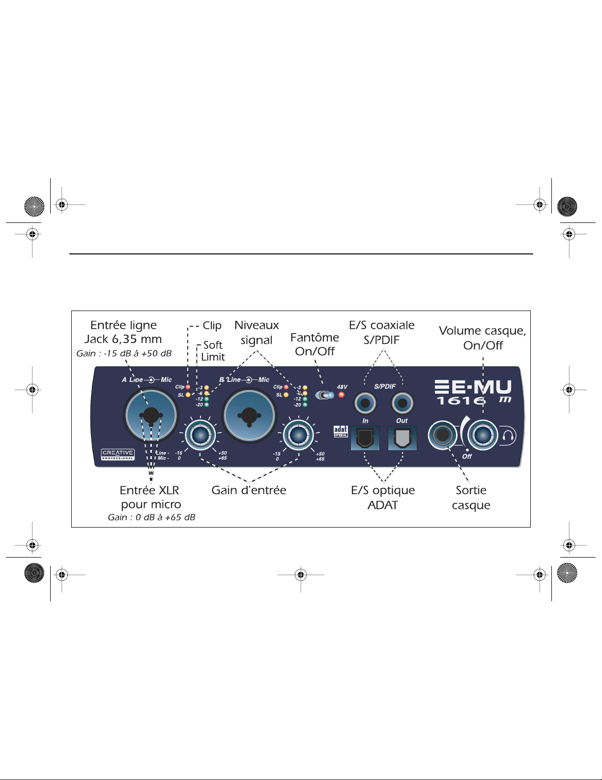
7 - MicroDock et MicroDock M
Le MicroDock se connecte à la carte E-MU 1010 PCI par le câble EDI. La face avant du MicroDock est équipée de 2 entrées
préampli micro/ligne symétriques, de 8 canaux d’entrées/sorties numériques ADAT, d’un connecteur d’entrée/sortie stéréo
S/PDIF et d’une sortie casque stéréo avec réglage de volume et mise sous/hors tension.
Connexions de face avant
30 - Système audio numérique E-MU PCI
Page 31

EMU GS(Fr).fm Page 31 Thursday, October 26, 2006 1:15 PM
Les entrées mono Mic/Line A et B de face avant peuvent être utilisées comme entrées micro
symétriques, comme entrées guitare haute impédance, ou comme entrées ligne symétriques. Les
connecteurs combinés Neutrik acceptent des connecteurs standards XLR ou des Jacks 6,35 mm
Section préampli
stéréo ou mono à niveau ligne ou haute impédance (guitare).
Attention :
Certains micros peuvent êtr e endommagés par l’alimentation fantôme. Consultez le
mode d’emploi du micro avant d’utiliser l’alimentation fantôme.
Chaque connecteur RCA dispose de deux canaux pour le son numérique. L’entrée et la sortie
numérique S/PDIF peuvent être utilisées pour la réception et/ou la transmission de données
Entrées/sorties
audionumériques
S/PDIF
numériques en provenance d’appareils numériques tels qu’un enregistreur, un convertisseur
analogique/numérique externe ou un processeur externe avec entrées et sorties numériques.
La sortie S/PDIF peut être configurée au format professionnel ou grand public (toujours en 24-bits).
les entrées/sorties S/PDIF sont compatibles avec les fréquences d’échantillonnage de 44,1kHz,
48 kHz, 96 kHz et 192 kHz.
• Les connecteurs optiques ADAT transmettent et reçoivent les informations sur 8 canaux à 24-bits
Entrée/sortie
numérique
optique ADAT
aux formats ADAT 1 et 2 (à 44,1 kHz ou 48 kHz).
• Les données Wordclock reçues en entrée peuvent être utilisées comme source d’horloge.
®
• Les ports optiques ADAT peuvent également porter un signal optique au format S/PDIF.
• Les données ADAT peuvent être reçues et transmises à 96 kHz ou 192 kHz au format S/MUX.
Le format S/MUX offre 4 canaux audio à 96 kHz et 2 canaux audio à 192 kHz.
La sortie casque permet la connexion de casques stéréo standards. Le bouton de volume
Sortie casque
et réglage de
volume
détermine le niveau d’écoute. Cette sortie est connectée de façon permanente à la sortie Monitor
Output de PatchMix DSP.
La sortie casque utilise une version à fort courant des sorties amplifiées des autres canaux.
Pour cette raison, le son est très propre et elle peut être utilisée comme sortie ligne stéréo.
Guide de mise en œuvre - Prise en main - 31
Page 32

EMU GS(Fr).fm Page 32 Thursday, October 26, 2006 1:15 PM
Connexions de face arrière
Vous disposez de quatr e entrées analogiques symétriques 24-bits à niveau ligne (stéréo 1-2). V ous
pouvez les utiliser pour connecter vos signaux à niveau ligne (clavier, lecteur de CD, de cassette,
Entrées
analogiques à
niveau ligne
etc.). Les entrées analogiques sont affectées aux voies de mixage de PatchMix DSP. Le niveau des
entrées ligne peut être réglé sur -10 dBV ou sur le niveau pro de +4 dBu dans la page I/O de la
fenêtre Session Settings. Vous pouvez utiliser des câbles en Jacks stéréo symétriques ou mono
asymétriques. Les câbles symétriques offrent une immunité plus importante aux bruits de fond et
un niveau de signal supérieur de 6 dB, mais vous pouvez utiliser des câbles instrument mono.
32 - Système audio numérique E-MU PCI
Page 33

EMU GS(Fr).fm Page 33 Thursday, October 26, 2006 1:15 PM
Vous disposez de six sorties analogiques symétriques 24-bits à niveau ligne (Stereo 1-3). La paire
de sorties 1 sert de sortie Monitor Out. Elle est en général alimentée par la sortie Monitor du
mélangeur de PatchMix DSP. Toutes les sorties analogiques peuvent être libr ement affectées dans
Sorties
analogiques à
niveau ligne
l’application de mixage. Une temporisation spéciale coupe ces sorties lors de la mise sous tension
pour éviter les bruits de pop. Comme pour les entrées ligne analogiques, vous pouvez utiliser des
câbles en Jacks symétriques ou asymétriques. Les câbles symétriques offrent une immunité plus
importante aux bruits de fond et un niveau de signal supérieur de 6 dB, mais vous pouvez utiliser
des câbles instrument mono. Le niveau des sorties ligne peut être réglé sur -10 dBV ou sur le
niveau pro de +4 dBu dans la page I/O de la fenêtre Session Settings
Entrée platine
et plot de
masse
Les entrées platine en RCA alimentent un préamplificateur RIAA conçu pour accepter les cellules
phono magnétiques. Les entrées Phono utilisent les mêmes circuits que les entrées ligne 2L et 2R.
Insérez un connecteur dans l’entrée ligne 2 pour déconnecter l’entrée Phono. Connectez le fil de
masse de votre platine au plot de masse pour éviter les ronflements.
Connectez le câble MIDI spécial fourni à l’embase MIDI située en face arrière du MicroDock.
Les ports d’entrée et de sortie MIDI vous permettent d’utiliser tout type d’appareils MIDI comme
E/S MIDI 1et 2
les claviers, les processeurs d’effets, les boîtes à rythmes, ou les guitares MIDI. Les Drivers MIDI ont
été installés lors de l’installation de Patchmix DSP. Les ports MIDI s’affichent dans le panneau de
contrôle de votre système dans “Sons et périphériques audio”.
Sorties
supplémentaires
Connecteur EDI
Ces mini-Jacks stéréo (3,5 mm) reprennent les signaux des sorties ligne 1-3. Ces sorties à niveau
ligne ont été conçues pour permettre la connexion directe à vos enceintes informatiques
amplifiées.
Connecte le MicroDock à la carte 1010 PCI E-MU à l’aide du câble CAT 5e. Le câble fourni avec le
MicroDock est spécialement blindé pour éviter toute émission HF parasite (interférences).
Guide de mise en œuvre - Prise en main - 33
Page 34

EMU GS(Fr).fm Page 34 Thursday, October 26, 2006 1:15 PM
8 - Carte fille de synchronisation E-MU
La carte fille de synchronisation fournit une entrée et une sortie « word clock », une entrée et une sortie SMPTE (LTC, code
temporel longitudinal) et une sortie MIDI supplémentaire pour transmettre le code temporel MIDI (MTC, code temporel
MIDI). Le code temporel MIDI est un rendu spécial de SMPTE qui peut être transmis via des câbles MIDI.
Note : Quand la carte de synchro est installée, le MIDI 2 sur le MicroDock est handicapé. (MTC emploie le port du MIDI.)
Le « word clock » est un moyen standard de synchroniser deux équipements numériques ou plus au taux d’échantillonnage du système (44,1 kHz, 48 kHz, 96 kHz ou 192 kHz). Pour éviter la corruption des données, les équipements
numériques DOIVENT être synchronisés.
L’équipement d’enregistrement doit également être synchr onisé à l’aide de la synchr onisation SMPTE ou MTC afin que deux
enregistreurs audio ou un enregistreur audio et vidéo puissent fonctionner ensemble comme une seule et unique
machine. Pour plus d’informations, reportez-vous au manuel de l’utilisateur (sur CD).
(facultatiff )
Connexions
Entrée « word clock » : Reçoit un « word clock » (horloge d’échantillonnage) en
provenance d’un autre appareil numérique tel qu’une platine vidéo numérique, un
Entrées et sorties
« word clock »
Entrée/sortie
SMPTE
Sortie MTC
enregistreur numérique ou un mixeur numérique.
Sortie « word clock » : Envoie un « word clock » (horloge d’échantillonnage) à un autre
enregistreur numérique. Le « wor d clock » est toujours une sortie, qu’elle soit générée par
l’horloge interne ou qu’elle passe par l’entrée « word clock ».
L’entrée SMPTE convertit le code temporel longitudinal SMPTE (LTC) en code temporel MIDI
(MTC) puis transmet cette information à l’ordinateur hôte qui doit être utilisé comme
application de séquençage ou d’enregistrement audio. Lorsque votre application
informatique est « maître », le MTC généré par l’application informatique est converti en
SMPTE puis envoyé vers un autre appareil SMPTE tel qu’un autre enregistreur audio afin
de le synchroniser avec le séquenceur.
Cette sortie transmet le code temporel MIDI à un autre ordinateur ou à un autre
enregistreur audio. La source du MTC peut provenir d’une entrée SMPTE ou séquenceur.
34 - Système audio numérique E-MU PCI
Page 35

EMU GS(Fr).fm Page 35 Thursday, October 26, 2006 1:15 PM
Licence et copyright
Les informations dans ce document peuvent faire l'objet de modifications sans préavis et ne constituent pas un
engagement de la part de E-MU Systems, Inc. Ce manuel ne peut être r eproduit ou transmis même partiellement sous
une forme ou une autre ou de quelque manièr e que ce soit, électronique ou mécanique, sous forme de photocopie
et d'enregistrement, à des fi ns quelconques sans l'autorisation écrite préalable de E-MU Systems, Inc. Le logiciel décrit
dans ce document est fourni sous contrat de licence et ne peut être utilisé ou copié que conformément aux termes
et conditions du contrat de licence. Il est illégal de copier le logiciel sur un autre support, excepté tel qu'autorisé spécifiquement dans l'accord de licence. Le détenteur de la licence peut effectuer une copie du logiciel à des fi ns de sauvegarde.
E-MU est une marque déposée de E-MU Systems, Inc. aux Etats-Unis et/ou dans d'autres pays.
Copyright © 2006 par E-MU Systems, Inc. Tous droits réservés.
Version 1.82
Avril 2006
Ce petit symbole indique que ce produit ne peut pas être traité
comme un déchet ménager. En veillant à vous débarrasser
correctement de ce produit, vous participerez activement à la
protection de l'environnement. Pour de plus amples détails sur le
recyclage de ce produit, consultez les autorités compétentes
locales, votre centre de traitement des déchets ou votre revendeur.
Guide de mise en œuvre - Prise en main - 35
Page 36

EMU GS(Fr).fm Page 36 Thursday, October 26, 2006 1:15 PM
36 - Système audio numérique E-MU PCI
Page 37

EMU GS (Dt).fm Page 37 Monday, October 30, 2006 11:27 AM
1 - Einführung
Wir beglückwünschen Sie zum Kauf des Digital Audio-Systems E-MU 1212
m
, E-MU 1616 oder E-MU 1616
Entwicklung der E-MU Digital Audio-Systeme standen vor allem der logische Aufbau und die intuitive Bedienung des
Produkts sowie die Erzielung einer reinen Klangqualität im Vordergrund. Alle drei Systeme bieten echte Studioqualität und
Mehrkanalaufnahme und -wiedergabe mit 24 Bit/192 kHz zu einem erstaunlich günstigen Preis.
Systemanforderungen
• Echter Intel
®
oder AMD
• Intel-, AMD- oder 100%-ig kompatible Hauptplatine und Chipset
• Windows XP (SP2), Windows 2000 (SP4), or x64
• 256 MB RAM
• 900 MB freier Festplattenspeicher für die vollständige Installation.
• PCI 2.1-kompatibler Kartensteckplatz (Für E-MU 1212
• XVGA Video (1024 x 768)
• CD-ROM/CD-RW or DVD-ROM-Laufwerk für die Softwareinstallation.
• Kopfhörer oder verstärkte Lautsprecher
Für weitere Anwendungen sind ggf. höhere Systemanforderungen oder ein Mikrofon erforderlich.
®
-Prozessor mit 1 GHz oder schneller
m
werden zwei Steckplätze benötigt.)
Inhalt des Pakets
E-MU 1212
• E-MU 1010 PCI-Karte
• E-MU 0202-E/A-Tochterkarte
• Flachbandkabel für E/ATochterkarte
•2 Mini-MIDI-Kabel
• Digital Audio System Software/
Treiber Installations-CD
•Produktions-Tools SoftwareBundle-CD
• Handbuch „Erste Schritte“
m
PCI E-MU 1616 PCI E-MU 1616
• E-MU 1010 PCI-Karte
•MicroDock
• EDI-Kabel (digitales E-MUSchnittstellenkabel)
• +48VDC AC-Adapter
• Konverterkabel
• D.A.S. Software/Treiber Installations-CD
•Produktions-T ools Softwar e-Bundle-CD
• Handbuch „Erste Schritte“
• E-MU 1010 PCI-Karte
•MicroDock M
•EDI-Kabel (digitales E-MU-Schnittstellenkabel)
• Konverterkabel
•
+48VDC AC-Adapter
• D.A.S. Software/Treiber Installations-CD
•Produktions-T ools Softwar e-Bundle-CD
• Handbuch „Erste Schritte“
Schnellstart-Anleitung - Erste Schritte - 37
m
PCI
m
. Bei der
Page 38

EMU GS (Dt).fm Page 38 Monday, October 30, 2006 11:27 AM
Sicherheit
Damit Sie sich nicht verletzen oder Teile der Ausrüstung beschädigt werden, müssen Sie bei der Installation der
Hardwarekomponenten die folgenden allgemeinen Vorsichtsmaßnahmen beachten.
• Um mögliche permanente Schäden an der Hardware auszuschließen, werden die E-MU 1010-Karte und das MicroDock
angeschlossen, während der Hostcomputer ausgeschaltet ist.
Entfernen Sie das Netzkabel vom Computernetzteil. Auf diese Weise ist sichergestellt, dass der Computer
sich nicht doch noch im Energiesparmodus befindet.
• Achten Sie darauf, dass keine elektrostatischen Schäden an den Komponenten des Systems verursacht werden. Die
Innenflächen des Computers, die E-MU 1010 PCI-Karte und die Schnittstellen können leicht durch elektrostatische (auch als
„statische“ bezeichnete) Entladungen beschädigt werden. Durch eine elektrostatische Entladung können elektronische
Geräte beschädigt oder sogar zerstört werden. Befolgen Sie beim Umgang mit elektronischen Geräten die folgenden
Vorgehensweisen, um die Wahrscheinlichkeit elektrostatischer Schäden so gering wie möglich zu halten:
•Vermeiden Sie beim Umgang mit elektronischen Geräten jegliche unnötige Bewegung, z. B. auch mit den Füßen über den
Boden zu schurren, da sich infolge solcher Bewegungen zusätzliche statische Ladungen aufbauen können.
• Beschränken Sie den Umgang mit der PCI-Karte auf das Nötige. Die Karte bleibt in der antistatischen Packung, bis sie
wirklich benötigt wird. Transportieren oder lagern Sie die Karte nur in der Schutzverpackung.
•Vermeiden Sie beim Umgang mit der PCI-Karte, die Kontakte zu berühren. Halten Sie die Karte nur am Rand.
• Bevor Sie eine PCI-Karte in den Computer einbauen, müssen Sie sich erden. Tragen Sie ein Erdungsband, um die eventuelle
statische Aufladung Ihres Körpers abzuleiten. Befestigen Sie das Erdungsband dazu an Ihrem Handgelenk, und halten Sie
es an eine unlackierte metallische Innenfläche des Computergehäuses.
Abrufen weiterer Informationen
Detaillierte Informationen zu E-MU Digital Audio System und den verschiedenen Softwareanwendungen finden Sie in den
betreffenden Dateien der Onlinehilfe oder im Benutzerhandbuch (auf CD).
Nach der Software-Installation: Klicken Sie auf das E-MU Icon in der Windows SysTray, um PatchMix DSP zu öffnen,
und klicken Sie dann auf das Icon in der oberen rechten Ecke, um das vollständige Bedienungshandbuch zu öffnen.
?
Technischer Support
E-MU Digital Audio System wird ständig erweitert. Sicher möchten Sie immer über neue Software und Optionen für E-MU Digital
Audio System informiert sein. Diese und viele andere interessante Informationen finden Sie unter
nummer des technischen Support entnehmen Sie dem auf CD enthaltenen Benutzerhandbuch.
38 - E-MU PCI Digital Audio System
www .emu.com . Die Telefon-
Page 39

EMU GS (Dt).fm Page 39 Monday, October 30, 2006 11:27 AM
2 - Hardwareinstallation
Metallsicherheits-klammern
PCI Steckplaetze
ISA
Steckplaetze
Schritt 1: Vorbereiten des Computers
1. Schalten Sie den Computer und alle Peripheriegeräte aus.
2. Berühren Sie eine Metallfläche des Computers, um sich zu erden und eventuelle statische
Aufladungen abzuleiten. Entfernen Sie anschließend das Netzkabel vom Computernetzteil.
3. Entfernen Sie die Abdeckung des Computers.
4. Entfernen Sie das Metall, das Clip von einem PCI Schlitz sichert. Wenn Sie das E-MU 1212m
System haben oder die Sync-Tochterkarte anbringen, entfernen Sie das Metall, das Clip
von zwei PCI Schlitz sichert. Siehe Abbildung links.
Schritt 2: Installieren der E-MU 1010 PCI-Karte
1. Richten Sie die E-MU 1010 PCI-Karte am Steckplatz aus, und schieben Sie sie dann
vorsichtig aber fest in den Steckplatz, wie in der Abbildung links.
2. Die E-MU 1010-Karte darf nicht gewaltsam in den Steckplatz geschoben werden. Achten
Sie darauf, dass der vergoldete Kontaktstift der Karte am PCI-Bus-Kontakt der Hauptplatine
ausgerichtet ist, bevor Sie die Karte in den PCI-Steckplatz schieben. Sollte die Karte sich
nicht ordnungsgemäß einpassen, entfernen Sie sie und versuchen es erneut.
3. Befestigen Sie die Karte (ggf.) mit einer Schraube am Steckplatz.
Schnellstart-Anleitung - Erste Schritte - 39
Page 40
EMU GS (Dt).fm Page 40 Monday, October 30, 2006 11:27 AM
Schritt 3: Installieren der 0202 E/A-Tochterkarte
Hinweis: Dieser Schritt ist nur für Benutzer von E-MU 1212
1616M, gehen zu Schritt 5 weiter
1. Verbinden Sie die E-MU 1010-Karte und die 0202 E/A-Tochterkarte mit dem im Set
enthaltenen Flachbandkabel wie in der Abbildung unten. Die Kabelanschlüsse sind
kodiert, um ein falsches Anschließen zu vermeiden. Stecken Sie die Kabelanschlüsse fest
auf die entsprechenden Stecker der Karte, und achten Sie darauf, dass das Kabel dabei
nicht verdreht ist.
2. Befestigen Sie die E-MU Sync- bzw . E/A-Tochterkarte ggf. mit einer weiteren Schraube an
dem Steckplatz neben der E-MU 1010-Karte.
3. Bringen Sie die Abdeckung des Computers wieder an.
4. Schließen Sie das Netzteil und die Peripheriegeräte wieder an den Computer an, und
schalten Sie den Computer ein.
5. Wechseln Sie zu Kapitel 3 „Installieren der Software“.
Schritt 4: Installieren der Sync-Tochterkarte
Hinweis: Dieser Schritt ist nur für Benutzer von sync-Tochterkarte. Andernfalls gehen Sie zu
Abschnitt 3 weiter.
1. Verbinden Sie die E-MU 1010-Karte und die Sync-Tochterkarte mit dem im Set
enthaltenen Flachbandkabel wie in der Abbildung unten. Die Kabelanschlüsse sind
kodiert, um ein falsches Anschließen zu vermeiden. Stecken Sie die Kabelanschlüsse fest
auf die entsprechenden Stecker der Karte, und achten Sie darauf, dass das Kabel dabei
nicht verdreht ist.
2. Befestigen Sie die E-MU Sync-Tochterkarte ggf. mit einer weiteren Schraube an dem
Steckplatz neben der E-MU 1010-Karte.
3. Bringen Sie die Abdeckung des Computers wieder an.
4. Schließen Sie das Netzteil und die Peripheriegeräte wieder an den Computer an, und
schalten Sie den Computer ein.
5. Wechseln Sie zu Kapitel 3 „Installieren der Software“.
40 - E-MU PCI Digital Audio System
m
. Benutzer von E-MU 1616/
(wahlweise freigestellt)
0202 E/A-Tochterkarte
E-MU Sync-Tochterkarte
Page 41

EMU GS (Dt).fm Page 41 Monday, October 30, 2006 11:27 AM
Schritt 5: Anschließen des MicroDocks an die E-MU 1010-Karte
Verbinden Sie mithilfe des beiliegenden Netzwerkkabels die RJ-45-Buchse der E-MU 1010 PCI-Karte mit der Aufschrift „EDI“
mit dem MicroDock-Anschluss mit der Aufschrift „EDI“.
Das Kabel ist ein standardmäßiges CAT 5e-Netzwerkkabel, das zur Verhinderung von HF-Emissionen besonders geschirmt
ist. Wenn Sie ein Ersatzkabel benötigen, wenden Sie sich an E-MU Systems.
VORSICHT: Schließen Sie das beiliegende CAT 5e-Kabel unter keinen Umständen an den Ethernet- oder Netzwerkan-
schluss des Computers an, da der Computer, die E-MU 1010 oder beide auf diese Weise ernsthaft beschädigt werden
können.
MicroDock mit Spannung versorgen
Das MicroDock wird über den mitgelieferten +48V DC-Adapter mit Spannung versorgt. Schließen Sie den Adapter an die
rückseitige +48VDC Buchse des MicroDock an. Schalten Sie das MicroDock ein, indem Sie den Kopfhörer-Pegelregler
aufdrehen.
+48V DC-Adapter
Der Kopfhörer-Pegel-
1010 PCI Card
regler dient auch als
Netzschalter.
Schnellstart-Anleitung - Erste Schritte - 41
Page 42

Ja
EMU GS (Dt).fm Page 42 Monday, October 30, 2006 11:27 AM
3 - Installieren der Software
Installieren und Deinstallieren der E-MU 1010-Treiber und -Anwendungen
Beim ersten Start des PC nach der Installation der E-MU 1010 PCI-Karte müssen die E-MU 1010 PCI-Kartentreiber und die
Software PatchMix DSP installiert werden.
Windows XP,
1. Schalten Sie den Computer nach der Installation der Audiokarte ein. Windows erkennt die Audiokarte automatisch und sucht
nach den Gerätetreibern.
2. Bei der Eingabeaufforderung für die Audiotreiber klicken Sie auf die Schaltfläche Abbrechen.
3. Legen Sie die Installations-CD für die E-MU-Software in das CD-ROM-Laufwerk des Computers ein.
Wenn in Windows für das CD-ROM-Laufwerk die automatische Wiedergabe aktiviert ist, wird die CD automatisch gestartet.
Sollte das nicht der Fall sein, klicken Sie auf dem Windows-Desktop auf Start->Ausführen und geben d:\setup.exe ein ( d:\
ist ggf. durch den Buchstaben für das CD-ROM-Laufwerk zu ersetzen). Sie können aber auch einfach die CD öffnen und
setup.exe doppelklicken.
4. Der Startbildschirm des Installationsvorgangs wird angezeigt. Befolgen Sie die Anweisungen auf dem Bildschirm, um die
Installation abzuschließen.
5. Wenn der Bildschirm mit der Warnung zum Windows Logo-Test angezeigt wird, klicken Sie auf Installation fortsetzen.
6. Starten Sie den Computer neu, sobald Sie dazu aufgefordert werden.
Windows 2000, x64
Deinstallieren der Audiotreiber und -anwendungen
In bestimmten Situationen kann es im Rahmen der Fehlerbehebung, der Änderung von Konfigurationen oder der Aktualisierung
veralteter T reiber oder Anwendungen erforderlich werden, einen Teil oder alle Anwendungen und Gerätetreiber für die Audiokarte zu
entfernen. Bevor Sie damit beginnen, müssen alle Anwendungen der Audiokarte geschlossen werden, da während der Deinstallation
ausgeführte Anwendungen nicht entfernt werden.
1. Klicken Sie auf Start -> Einstellungen -> Systemsteuerung .
2. Doppelklicken Sie auf das Symbol Software.
3. Klicken Sie auf die Registerkarte
entfernen
4. Markieren Sie den Eintrag für die E-MU 1010 PCI-Karte oder die entsprechende Anwendung,
und klicken Sie dann auf die Schaltfläche
5. Wählen Sie im Dialogfeld des
6. Klicken Sie auf die Schaltfläche
7. Starten Sie den Computer neu, sobald Sie dazu aufgefordert werden.
8. Die vorhandenen oder aktualisierten Gerätetreiber oder Anwendungen für die 1010 PCI-Karte können nun erneut installiert werden.
42 - E-MU PCI Digital Audio System
).
Installieren/Deinstallieren (oder die Schaltfläche Programme ändern oder
Hinzufügen/Entfernen (oder Ändern/Entfernen ).
InstallShield-Assistenten die Option Entfernen .
.
(Andere Windows-Versionen sind mit der Software nicht kompatibel.)
Page 43

EMU GS (Dt).fm Page 43 Monday, October 30, 2006 11:27 AM
4 - E-MU 1010 PCI-Karte und -Schnittstelle
Die E-MU 1010 PCI-Karte mit dem leistungsstarken E-DSP-Chip von E-MU bildet das Kernstück des Systems. Durch den
leistungsfähigen Hardware-DSP auf der Karte wird die CPU weitgehend für zusätzliche Software-Plugins und andere
Aufgaben entlastet.
Anschlüsse
Anschluss des MicroDocks über das EDI-Kabel (digitales E-MU-Schnittstellenkabel). Über
dieses Kabel wird das MicroDock mit Strom versorgt, und es wird eine bidirektionale
Datenverbindung zwischen der E-MU 1010-Karte und dem MicroDock hergestellt.
Jede RCA-Phonobuchse verfügt über zwei digitale Audiokanäle. Der digitale S/PDIF-E/A kann
sowohl für den Empfang als auch für die Übertragung digitaler Daten von externen Geräten
mit digitalen Ein- und Ausgängen verwendet wer den, wie z. B. einem DAT-Recor der, einem
externen Analog-Digital-Konverter oder einem externen Signalprozessor.
Die im Eingangsdatenstrom enthaltene clock kann als clock-Quelle verwendet werden.
Der S/PDIF-Ausgang kann im Professional- oder im Consumer-Modus mit einer Auflösung
von 24-Bit konfiguriert werden. Die S/PDIF-Ein- und -Ausgänge unterstützen
Samplefrequenzen von 44,1 kHz, 48 kHz und 96 kHz, für 192 kHz sind sie dagegen
deaktiviert.
Über die optischen ADAT-Anschlüsse werden in den ADAT-Formaten Typ 1 & 2 (44,1 kHz
oder 48 kHz) 8-Kanal-Audiodaten in 24-Bit-Qualität übertragen und empfangen. Die im
Eingangsdatenstrom enthaltene clock kann als clock-Quelle verwendet werden.
-
Die optischen ADAT-Anschlüsse können auch auf optisches S/PDIF umgeschaltet werden.
Bei Verwendung des S/MUX-Standards kann ADAT auch mit 96 kHz oder 192 kHz
übertragen oder empfangen werden, wobei die zusätzlichen Daten für mehrere Kanäle
verschlüsselt werden.
EDI-
Anschluss
S/PDIF
Ein- und
Ausgang
Optischer
ADAT Ein-
und Ausgang
EDI
EDIAnschluss
Digitaler
S/PDIFAudioeinund
-ausgang
Optischer
digitaler
®
ADAT
Eingang &
-Ausgang
Schnellstart-Anleitung - Erste Schritte - 43
Page 44

A
EMU GS (Dt).fm Page 44 Monday, October 30, 2006 11:27 AM
5 - Die E-MU 0202-E/A-Tochterkarte
Die E/A-Tochterkarte verfügt über zwei symmetrische 24 Bit-Analogeingänge und zwei symmetrische 24 Bit-Analogausgänge sowie einen MIDI-Eingang und einen MIDI-Ausgang. Die Karte bietet damit zusätzliche Analogein- und -ausgänge
und eine MIDI-Schnittstelle für E-MU Digital Audio Systems, die am MicroDock nicht vorhanden sind. Die E/A-Tochterkarte
belegt einen Extraplatz auf der Rückseite des Computers und wird mit einem 40-poligen Flachbandkabel an die E-MU 1010
PCI-Karte angeschlossen.
Anschlüsse
Linker/
rechter
Analog-
eingang
Linker/
rechter
Analog-
ausgang
MIDI
Ein- und
usgang
44 - E-MU PCI Digital Audio System
Analogeingänge
und -ausgänge
MIDI-Eingang/
Ausgang
Diese Eingänge können für Signale auf Line-Ebene verwendet werden, z.
B. von einem Keyboard, einem CD-Player, Kassettendeck usw. (Die
Analogeingänge werden im Rahmen der PatchMix DSP-Mixer-Anwendung
bestimmten Mixerreglern zugewiesen.)
Die Ausgänge können Signale an beliebige Line-Eingänge senden, z. B. an
ein Mischpult, den Aux-Eingang der Stereoanlage oder ein Paar Aktivboxen.
Es können symmetrische TRS- oder unsymmetrische TS-Kabel verwendet
werden. Symmetrische Kabel sind weniger anfällig für Störgeräusche und
bieten einen höheren Signalpegel (+6 dB). Der Line-Ausgangspegel kann
im Dialogfeld für die Sitzungseinstellungen im E/A-Bildschirm auf
Consumer-Pegel (Standard –10 dBV) oder Pro-Audio-Standard (+4 dBu)
eingestellt werden.
MIDI-Eingangs- und -Ausgangsanschluss werden im Rahmen der
entsprechenden MIDI-Anwendung zugewiesen. Schließen Sie das im
Lieferumfang der E/A-Tochterkarte enthaltene Adapterkabel an die MiniDIN-Anschlüsse der Karte an. Mithilfe der beiliegenden MIDI-Adapterkabel
können die Mini-DIN-Anschlüsse mit den bei den meisten Keyboards und
Synthesizern üblichen Standard-DIN-Anschlüssen verbunden werden.
Page 45

EMU GS (Dt).fm Page 45 Monday, October 30, 2006 11:27 AM
6 - Anschlüsse
Elementare
Anschlüsse
MIDI-Synthesizer
MIDI In
MIDI Out
Out
MIDI 1
In
Plattenspieler
Audio
vom
Synthesizer
**
Pho no
2L
2R
1L
In
Out
1L
2L
1R
1R
2L
2R
2R
3R
3L
Audio
zu den
Monitoren
Mischer
&
Boxen
* Hinweis: Die Line Inputs 2L/2R und Phono 2L/2R können nicht gleichzeitig benutzt werden.
Gnd
1
1/8" Buchsen
anschließen
MIDI Cable
Out
2
Desktop-
Boxen an
e
t
S
48
VDC
+
-
3
EDI
AC-Adapter
1010
PCI-Karte
DesktopAktivboxen
e
r
o
Schnellstart-Anleitung - Erste Schritte - 45
Page 46

EMU GS (Dt).fm Page 46 Monday, October 30, 2006 11:27 AM
46 - E-MU PCI Digital Audio System
Page 47

EMU GS (Dt).fm Page 47 Monday, October 30, 2006 11:27 AM
Schnellstart-Anleitung - Erste Schritte - 47
Page 48

EMU GS (Dt).fm Page 48 Monday, October 30, 2006 11:27 AM
7 - MicroDock & MicroDock M
Das MicroDock wird über das EDI-Kabel mit der E-MU 1010 PCI Card verbunden. Auf der Vorderseite des MicroDock
befinden sich 2 symmetrische Mic/Line Preamp-Eingänge, ADAT Digital-Eingänge/Ausgänge mit 8 Kanälen, Stereo S/PDIF
Digital-Eingang/Ausgang sowie ein Stereo-Kopfhörerausgang mit Pegelregler/Netzschalter.
Vorderseitige Anschlüsse
48 - E-MU PCI Digital Audio System
Page 49

EMU GS (Dt).fm Page 49 Monday, October 30, 2006 11:27 AM
Die vorderseitigen Mono Mic/Line-Eingänge A & B sind als symmetrische Mikrofon-Eingänge,
hochohmige Gitarren-Pickup-Eingänge oder symmetrische Line-Pegel-Eingänge einsetzbar. Die
PreampSektion
Neutrik-Kombibuchse akzeptiert Mikrofone mit standard XLR-Anschluss oder Line-Pegel/
hochohmige Eingänge mit 1/4“ TRS-Klinkenstecker.
Warnung: Manche Mikrofone können durch Phantomspannung beschädigt werden. Prüfen Sie
vor dem Einsatz von Phantomspannung die Spezifikationen und Anforderungen des Mikrofons.
Jeder Cinch-Stecker überträgt zwei Kanäle mit Digitalaudio. Der S/PDIF Digital I/O ist einsetzbar für den
S/PDIF Digitalaudio Eingang
& Ausgang
Empfang/die Übertragung von Digitaldaten von/zu externen Digitalgeräten, wie DA T Player, externer
A/D-Konverter oder externer Signalprozessor mit Digital-Eingängen/Ausgängen.
Der S/PDIF-Ausgang kann als Professional- oder Consumer -Modus (immer mit 24-Bit Auflösung) konfiguriert
werden. Die S/PDIF Ein-/Ausgänge unterstützen die Sampleraten 44.1kHz, 48kHz, 96kHz & 192kHz.
• Die optischen ADAT-Anschlüsse senden und empfangen 8 Kanäle mit 24-Bit Audio im ADAT Type 1
®
ADAT
Optische
DigitalEingänge &
Ausgänge
& 2 Format (bei 44.1kHz oder 48kHz).
• Die im Eingangs-Datenstrom enthaltene Word Clock kann als Word Clock-Quelle benutzt werden.
• Die optischen ADAT-Ports können auch auf die Übertragung von optischem S/PDIF umgeschaltet
werden.
• ADAT kann auch unter Verwendung des S/MUX Standards mit 96kHz oder 192kHz gesendet/
empfangen werden. S/MUX bietet 4 Audiokanäle bei 96kHz und 2 Audiokanäle bei 192kHz
Samplerate.
Der Kopfhörerausgang eignet sich für standard Ster eo-Kopfhörer und der benachbarte Pegelr egler
Kopfhörerausgang &
Pegelregler
steuert den Abhörpegel. Dieser Ausgang ist fest mit dem Monitor Output in PatchMix DSP
verbunden.
Der Kopfhörer-Ausgang benutzt eine Hochspannungsversion der hochwertigen Ausgangsverstärker der anderen Kanäle. Er liefert daher ein sehr sauberes Signal, das bei Bedarf als
zusätzlicher Stereo-Ausgang einsetzbar ist.
Schnellstart-Anleitung - Erste Schritte - 49
Page 50

EMU GS (Dt).fm Page 50 Monday, October 30, 2006 11:27 AM
Rückseitige Anschlüsse
Es sind vier symmetrische, analoge 24-Bit Line-Pegel-Eingänge (Stereo 1-2) zum Einspeisen der
Line-Pegel-Signale von Keyboards, CD-Playern, Cassettendecks etc. verfügbar. (Die Analogeingänge werden in der PatchMix DSP Mischer-Software Mischerkanalzügen zugewiesen.) Auf
analoge LinePegel-Eingänge
dem I/O Screen der Session Settings-Dialogbox kann der Line-Eingangspegel auf den Consumer 10dBV Standard oder den Pro-Audio +4 dBu Standard eingestellt werden.
Es sind symmetrische TRS- oder asymmetrische TS-Kabel einsetzbar. Symmetrische Kabel sind
rauschärmer und liefern einen +6dB höheren Signalpegel, aber standard Mono-Instrumentenkabel funktionieren auch gut.
50 - E-MU PCI Digital Audio System
Page 51

EMU GS (Dt).fm Page 51 Monday, October 30, 2006 11:27 AM
Es sind sechs symmetrische, analoge 24-Bit Line-Pegel-Ausgänge (Stereo 1-3) verfügbar.
Das Ausgangspaar 1 ist als Monitor-Ausgang konzipiert und wird normalerweise vom MonitorAusgang der PatchMix DSP Mischer-Software gespeist. Alle Analogausgänge sind in der Mischer-
analoge LinePegelAusgänge
Applikation frei zuweisbar. Eine spezielle Antipop-Schaltung schaltet die Analogausgänge beim
Ein-/Ausschalten des Geräts stumm.
Wie bei den analogen Line-Eingängen sind symmetrische TRS- oder asymmetrische TS-Kabel
verwendbar. Symmetrische Kabel sind rauschärmer und liefern einen +6dB höheren Signalpegel,
aber standard Mono-Instrumentenkabel funktionieren auch gut.
Auf dem I/O Screen der Session Settings-Dialogbox kann der Line-Ausgangspegel auf den
Consumer -10dBV Standard oder den Pro-Audio +4 dBu Standard eingestellt werden.
Die Plattenspieler-Cinch-Eingänge speisen einen RIAA entzerrten Phono-Preamp, der Dr ehmagnet-
PlattenspielerEingänge &
Erdungsanschluss
Phono-T onabnehmer akzeptiert. Die Plattenspieler -Eingänge laufen über die Line-Pegel-Eingänge
2L und 2R. Wird ein Stecker an Line Input 2 angeschlossen, wird der Phono-Preamp von diesem
Kanal getrennt. Verbinden Sie das Erdungskabel des Plattenspielers mit dem PlattenspielerErdungsanschluss, um Brummen zu vermeiden.
Verbinden Sie das mitgelieferte MIDI Br eakout-Kabel mit dem MIDI Port-Anschluss auf der Rückseite
MIDI 1& 2
In/Out
des MicroDock. Über die MIDI Ein- und Ausgangs-Ports können Sie alle MIDI-Geräte, z. B.
Keyboards, Effektgeräte, Drum Machines oder Gitarren-Controller, integrieren. Die MIDI-Treiber
wurden mit Ihrer Patchmix DSP Software installiert und die MIDI Ports erscheinen in der
Systemsteuerung unter “Sounds und Audiogeräte”.
Alternative
Ausgänge
Diese Stereo-Mini-Klinkenbuchsen (3.5 mm) duplizieren die Line-Pegel-Ausgänge 1-3 und sind
für die einfache Verbindung mit Computer-Aktivboxen konzipiert.
Verbindet das MicroDock über ein CAT 5e Computerkabel mit der E-MU 1010 PCI Card. Das mit
EDI-Anschluss
dem MicroDock gelieferte Kabel ist speziell abgeschirmt, um unerwünschte RF-Emissionen zu
verhindern.
Schnellstart-Anleitung - Erste Schritte - 51
Page 52

EMU GS (Dt).fm Page 52 Monday, October 30, 2006 11:27 AM
8 - Die E-MU Sync-Tochterkarte
Die Sync-Tochterkarte bietet Ein- und Ausgänge für Wordclock, SMPTE (LTC) und einen zusätzlichen MIDI-Ausgang zur
Übertragung des MIDI-Zeitcodes (MTC). Der MIDI-Zeitcode ist eine besondere Form des SMPTE-Codes, die über MIDI-Kabel
übertragen werden kann.
Anmerkung: Wenn die Synchronisierung Karte angebracht wird, ist MIDI 2 auf dem MicroDock untauglich.
(MTC benutzt das MIDI E/A.)
Wordclock wird standardmäßig zur Synchronisierung von zwei oder mehreren digitalen Komponenten mit der Samplefrequenz des Systems (44,1 kHz, 48 kHz, 96 kHz oder 192 kHz) verwendet. Die einzelnen Bestandteile des digitalen Systems
MÜSSEN synchronisiert werden, damit keine Daten beschädigt werden.
Auch Aufnahmegeräte können mit SMPTE oder MTC sync synchronisiert werden. Auf diese Weise können beispielsweise
zwei Audiorecorder oder ein Audio- und ein Videorecorder zu einer funktionalen Einheit verbunden werden. Weitere Informationen dazu entnehmen Sie dem Benutzerhandbuch (auf CD).
(wahlweise freigestellt)
Anschlüsse
Wordclock-Eingang: Empfängt Wordclock-Signale (Sample-Clock) von einem anderen
WordclockEingänge und
-ausgänge
SMPTEEingang/
Ausgang
MTC-Ausgang
digitalen Gerät, beispielsweise von einem Videodeck, einem digitalen Recorder oder Mixer.
Wordclock-Ausgang: Sendet Wordclock-Signale (Sample-Clock) an einen anderen digitalen
Recorder. Wordclock ist unabhängig davon, ob die Daten intern erzeugt oder vom
Wordclock-Eingang weitergeleitet wurden, immer ein Ausgang.
Der SMPTE-Eingang konvertiert den eingehenden longitudinalen SMPTE-Zeitcode (LTC) in
MIDI-Zeitcode (MTC) und leitet diese Daten an den Hostcomputer weiter, sodass sie durch
eine Sequencer- oder andere Audior ecorderanwendung verwendet wer den können. W enn
es sich bei Ihrer Computeranwendung um den „Master“ handelt, wird der von dieser
Anwendung erzeugte MTC in SMPTE umgewandelt und an ein anderes SMPTE-Gerät, z. B.
einen anderen Audiorecor der, gesendet, damit das Gerät mit dem Sequencer synchronisiert
wird.
Dieser Ausgang überträgt den MIDI-Zeitcode an einen anderen Computer oder
Audiorecorder. Die Quelle des MTC kann der Sequencer oder der SMPTE-Eingang sein.
52 - E-MU PCI Digital Audio System
Page 53

EMU GS (Dt).fm Page 53 Monday, October 30, 2006 11:27 AM
Lizenz und Copyright
Die Informationen in diesem Dokument können ohne vorherige Ankündigung geändert werden und stellen keine
Verpflichtung seitens E-MU Systems, Inc. dar. Ohne ausdrückliche schriftliche Genehmigung von E-MU Systems, Inc.
darf kein T eil dieses Dokuments in irgendeiner Form mit ir gendwelchen Mitteln elektronischer oder mechanischer Art,
einschließlich Fotokopie und Aufnahme, reproduziert oder übertragen werden. Die in diesem Dokument beschriebene
Software wird im Rahmen einer Lizenzver einbarung zur V erfügung gestellt und darf nur in Übereinstimmung mit den
Bestimmungen der Lizenzvereinbarung verwendet oder kopiert werden. Es ist gesetzeswidrig, die Software unter
Verwendung eines anderen Speichermediums als des in der Lizenzver einbarung festgelegten zu kopieren. Der Lizenznehmer ist berechtigt, eine Kopie der Software zu Sicherungszwecken zu erstellen.
E-MU ist eine eingetragene Marke der E-MU Systems, Inc. in den USA und/oder anderen Ländern.
Copyright © 2006 by E-MU Systems, Inc. Alle Rechte vorbehalten.
Version 1.82
April 2006
Das WEEE-Symbol weist Sie darauf hin, dass dieses Produkt nicht
als Hausmüll behandelt werden darf. Indem Sie eine korrekte Entsorgung des Produkts sicherstellen, tragen Sie zum Umweltschutz
bei. Nähere Informationen über das Recycling dieses Produkts erhalten Sie bei der zuständigen Verwaltungsbehörde, der Müllabfuhr
oder dem Geschäft, in dem Sie das Produkt gekauft haben.
Schnellstart-Anleitung - Erste Schritte - 53
Page 54

EMU GS (Dt).fm Page 54 Monday, October 30, 2006 11:27 AM
54 - E-MU PCI Digital Audio System
Page 55

1616 GS (SP).fm Page 55 Monday, October 30, 2006 11:41 AM
1 - Introducción
Felicidades y gracias por comprar el sistema audio digital E-MU 1212M, E-MU 1616 o E-MU 1616M. Hemos diseñado este
E-MU Digital Audio System para que sea lógico, intuitivo y, por encima de todo, para ofrecerle la máxima calidad de
sonido. Ambos sistemas le ofrece una auténtica calidad de estudio y grabación y reproducción multicanal de 24 bits/
192kHz a un precio verdaderamente increíble.
Requisitos del sistema
•Procesador Intel
®
o AMD
• Placa base y chipset Intel, AMD o 100% compatible
• Sistema operativo Windows XP (SP2), Windows 2000 (SP4), or x64
• 256 MB de memoria RAM
• 900 MB de espacio en el disco duro para la instalación completa.
• Una ranura PCI (PCI 2.1) disponible. (Dos ranuras necesitaron para E-MU el 1212M)
• Placa de vídeo XVGA (1024 x 768)
• Unidad de CD-ROM/CD-RW o DVD-ROM para la instalación del software.
• Auriculares o altavoces autoamplificados
Otros programas pueden necesitar requisitos del sistema superiores o el uso de un micrófono.
®
que funcione a una velocidad de 1 GHz o superior
Elementos incluidos
E-MU 1212
• T arjeta PCI E-MU 1010
• T arjta E/S secundaria E-MU 0202
• Cable de tarjeta E/S 0202
• Cables adaptador MIDI (2)
• CD-ROM de instalación de driver/softwar e
del Sistema de audio digital E-MU
• CD-ROM con paquete de programas de
herramientas de producción
•Manual de arranque rápido
m
PCI E-MU 1616 PCI E-MU 1616
•Tarjeta PCI E-MU 1010
• MicroDock
• Adaptador AC +48 VDC
• Cable EDI (Interface digital E-MU)
• Cable de ruptura MIDI
• CD de instalación de driver/software
del Sistema de audio digital E-MU
• CD con paquete de programas de
herramientas de producción
• Este manual de Inicio rápido
•Tarjeta PCI E-MU 1010
• MIcroDock M
• Adaptador AC +48 VDC
• Cable EDI (Interface digital E-MU)
• Cable de ruptura MIDI
• CD de instalación de driver/software
del Sistema de audio digital E-MU
• CD con paquete de programas de
herramientas de producción
• Este manual de Inicio rápido
Manual de arranque rápido - Preparativos - 55
m
PCI
Page 56

•
1616 GS (SP).fm Page 56 Monday, October 30, 2006 11:41 AM
¡La seguridad lo primero!
En la instalación de los componentes de hardware observe en todo momento las precauciones generales siguientes para
evitar daños en su equipo y en usted mismo.
Para evitar posibles daños permanentes en su hardware, asegúrese de realizar todas las conexiones con el ordenador
apagado. Quite el cable de corriente del ordenador para asegurarse de que no esté realmente “en
reposo” .
•Trate de evitar daños de corriente estática en cualquier parte de su sistema. Las superficies internas del ordenador, la
tarjeta PCI E-MU 1010 y los interfaces son susceptibles a descargas de electrostática, conocidos habitualmente como
“estática”. Estas descargas pueden dañar o destruir algunos dispositivos electrónicos. Trate por tanto de seguir los
procedimientos que existen para el manejo de dispositivos electrónicos de cara a reducir al mínimo el riesgo de este tipo
de daños:
• Evite los movimientos innecesarios, como ir arrastrando los pies mientras sujeta algún dispositivo electrónico, dado que
la mayoría de los movimientos pueden generar cargas adicionales de corriente estática.
• Sujete la tarjeta PCI durante el mínimo tiempo posible. Manténgala dentro de su embalaje anti-estática hasta que la
necesite. Transporte o guarde la tarjeta solo en su embalaje de protección.
• Cuando esté sujetando la tarjeta PCI, evite tocar las puntas de sus conectores. Trate de sujetar la placa solo por sus
bordes.
• Antes de instalar una tarjeta PCI en su ordenador, debería estar conectado a tierra. Utilice una banda de conexión a tierra
para descargar cualquier estática con la que pueda estar cargado su cuerpo. Sujete esta banda a su muñeca y a
cualquier parte metálica dentro de su ordenador. Si no tiene una de estas bandas, puede conectarse a tierra tocando la
carcasa metálica de cualquier aparato que sí esté conectado a tierra.
Después de la instalación del software: Haga clic en el icono E-MU de la bandeja de sistema Windows para
abrir el PatchMix DSP y después haga clic en el icono de la esquina superior derecha para hacer que se abra el manual
?
de instrucciones completo.
56 - E-MU Digital Audio System
Page 57

1616 GS (SP).fm Page 57 Monday, October 30, 2006 11:41 AM
2 - Instalación del hardware
Abrazadera metálica
Fig.1
ranuras
PCI
ranuras
ISA
Fig. 2
Paso 1: Prepare su ordenador
1. Asegúrese de que su ordenador esté apagado.
IMPORTANTE: Quite el enchufe de corriente de la salida!
2. Toque una lámina metálica en su ordenador para conectarse a tierra y descargar así
cualquier posible corriente estática que pudiese tener cargada en su cuerpo.
3. Siga el proceso recomendado por el fabricante del ordenador para abrir la carcasa.
4. Quite el soporte del metal a partir de una ranura del PCI. Si usted tiene el sistema de E-MU
el 1212m o está instalando la tarjeta de la hija de la sinc. usted necesitará quitar el soporte
a partir de dos ranuras del PCI. Vea la figura en la izquierda
Paso 2: Instale tarjeta PCI E-MU 1010
1. Alinee la tarjeta PCI E-MU 1010 con la ranura y empújela hacia dentro tal como puede ver
en la izquierda.
2. No introduzca la tarjeta E-MU 1010 a fuerza en la ranura. Asegúrese que el conector con el
símbolo del dedo dorado de la tarjeta esté alineado con el conector del bus PCI de la placa
base antes de introducir la tarjeta completamente en la ranura. Si no encaja
correctamente, saque la tarjeta y vuélvalo a intentar de nuevo.
3. Asegure la tarjeta en su posición en la ranura y fíjela por medio de los tornillos que quitó
anteriormente.
Manual de arranque rápido - Preparativos - 57
Page 58

1616 GS (SP).fm Page 58 Monday, October 30, 2006 11:41 AM
Paso 3: Instalación de la tarjeta secundaria 0202
Nota: Este paso está para los dueños de E-MU el 1212
1616M, se encienden al paso 5.
1. Conecte el cable en cinta que se incluye en el kit entre la tarjeta E-MU 1010 y la tarjeta
secundaria 0202, tal como le mostramos en las figuras 3 y 4. Los cables van con
muescas por lo que no puede colocarlos de forma incorrecta. Fije los conectores
firmemente en las tomas y recoja el cable todo lo posible.
2. Alinee la tarjeta secundaria de sincronización o la tarjeta 0202 con la ranura y empújela
hacia dentro tal como puede ver en la figura 2 de la página anterior.
m
solamente. Los dueños del 1616/
Paso 4: Instalación de la tarjeta secundaria sync
Nota: Este paso está para los dueños opcional E-MU
enciéndase a la sección 3 - Instalación de Software.
1. Conecte el cable en cinta que se incluye en el kit entre la tarjeta E-MU 1010 y la tarjeta
secundaria de sincronización, tal como le mostramos en las figuras 3 y 4. Los cables van
con muescas por lo que no puede colocarlos de forma incorrecta. Fije los conectores
firmemente en las tomas y recoja el cable todo lo posible.
2. Alinee la tarjeta secundaria de sincronización con la ranura y empújela hacia dentr o tal
como puede ver en la figura 2 de la página anterior.
tarjeta secundaria sync solamente. Si no,
Fig. 3
Fig. 4
58 - E-MU Digital Audio System
Page 59

1616 GS (SP).fm Page 59 Monday, October 30, 2006 11:41 AM
Paso 5: Conexión del MicroDock a la tarjeta E-MU 1010 PCI
Conecte el cable EDI incluido desde la clavija RJ-45 de la tarjeta PCI E-MU 1010 que viene marcada como “EDI” al conector
del mismo tipo marcado como “EDI” en el MicroDock.
Este es un cable standard de red CAT 5e con un blindaje especial para evitar las emisiones RF. Si necesita un cable de
recambio póngase en contacto con E-MU.
PRECAUCION: No conecte el MicroDock o la tarjeta 1010 PCI a los conectores Ethernet o de red. El hacer esto
puede producir un daño a su ordenador, al hardware E-MU o a ambos.
Conexión del MicroDock a la corriente
El MicroDock recibe la corriente del adaptador +48VDC incluido. Conecte el adaptador a la toma marcada como +48VDC
en e panel trasero del MicroDock. Encienda el MicroDock girando a la derecha el control de volumen de auriculares.
Adaptador +48V DC
El control de volumen
Tarjeta 1010 PCI
Manual de arranque rápido - Preparativos - 59
de los auriculares es
también el interruptor
de encendido.
Page 60

1616 GS (SP).fm Page 60 Monday, October 30, 2006 11:41 AM
3 - Instalación de software
Instalación y desinstalación de los Drivers y Aplicaciones del Digital Audio System
Instale el programa Patchmix DSP y los drivers la primera vez que arranque su PC después de instalar la tarjeta PCI E-MU 1010.
Windows XP, Windows 2000, x64
1. Una vez que haya instalado su tarjeta PCI 1010, encienda el ordenador. El sistema Windows detectará
automáticamente la tarjeta audio y buscará los drivers para ese dispositivo.
2. Cuando el Asistente de Nuevo Hardware solicite los drivers audio, haga clic en el botón Cancel .
3. Introduzca el CD de instalación de software E-MU en su unidad de CD-ROM. Si el modo de autoreproducción de
Windows está activado para su unidad de CD-ROM, el CD se ejecutará de forma automática. Si no, desde su
escritorio de Windows, haga clic en Inicio -> Ejecutar y teclee d:\setup.exe (sustituya d:\ si hace falta por la letra
de su unidad de CD-ROM). También puede sencillamente abrir el CD y hacer doble clic sobre setup.exe .
4. Aparecerá la ventana de inicio de instalación. Siga las instrucciones de pantalla para completar la instalación.
5. Elija la opción “Continue Anyway” cuando se encuentre con la pantalla de aviso “Windows Logo Testing”.
6. Cuando el programa se lo solicite, reinicie su ordenador.
(El software no es compatible con otras versiones de Windows).
Desinstalación de todos los drivers y aplicaciones audio
Puede que en algún momento tenga que desinstalar o reinstalar parte o todas las aplicaciones y drivers de la tarjeta audio
para corregir problemas, cambiar la configuración o actualizar algo. Antes de empezar, cierre todas las aplicaciones de la
tarjeta audio. Las aplicaciones que se sigan ejecutando durante la desinstalación no serán eliminadas.
1. Haga clic en Inicio -> Configuración -> Panel de control .
2. Haga doble clic en el icono Añadir/eliminar programas .
3. Haga clic en la pestaña Instalar/desinstalar (o el botón Cambiar o eliminar programas ).
4. Elija la entrada E-MU 1616 y haga clic en el botón Cambiar/eliminar .
5. En el cuadro de diálogo del Asistente de instalación , elija la opción Eliminar TODO .
6. Haga clic en el botón Sí .
7. Reinicie su ordenador cuando el programa así se lo indique.
8. Ahora puede volver a instalar o actualizar los drivers o aplicaciones de la tarjeta PCI E-MU 1010.
60 - E-MU Digital Audio System
Page 61

1616 GS (SP).fm Page 61 Monday, October 30, 2006 11:41 AM
4 - La tarjeta PCI E-MU 1010
The La tarjeta PCI E-MU 1010 es el corazón del sistema y contiene el potente chip E-DSP de E-MU. El poderoso hardware
DSP de esta tarjeta permite que en la CPU de su sistema quede más potencia libre para plug-ins de software adicionales y
otras tare
Conexiones
as.
Conéctelo al
MicroDock
a través de
cable EDI
Entrada/
salida
S/PDIF
Entrada/
salida ADAT
o S/PDIF
óptica
EDI
Conector
EDI
Entrada y
salida de
audio digital
S/PDIF
Entrada y
salida
digital
óptica
ADAT®
Le permite la conexión al MicroDock por medio del cable EDI incluido. Este cable le
ofrece un enlace de datos de dos vías entre el E-MU 1010 y el Micr oDock a la vez que
suministra corriente al MicroDock.
Cada uno de ellos lleva dos canales de audio digital.Puede usar esta E/S digital
S/PDIF para la recepción y/o transmisión de datos desde unidades digitales exteriores
como un convertidor analógico-digital DAT exterior o un procesador de señal exterior
que esté equipado con entradas y salidas digitales.
La salida S/PDIF puede ser configurada tanto en el modo profesional como en el
modo no-pro en el menú Session Settings.
Importante: S/PDIF I/O es lisiado en el PCI 1010 cuando el MicroDock está conectado.
Los conectores ópticos ADAT transmiten y reciben 8 canales de audio a 24 bits usando
los formatos 1 y 2 de tipo ADAT. (44.1kHz y 48kHz). La señal de r eloj wor d contenida en
la cadena de datos de entrada puede ser usada como fuente de reloj word. Los puertos
ópticos de ADAT se pueden también cambiar para llevar S/PDIF óptico
A las frecuencias de muestreo de 96 o 192 kHz, se usa el sistema standard S/MUX
entrelazado para la entrada y salida ADAT.
Importante: ADAT I/O es lisiado en el PCI 1010 cuando el MicroDock está conectado
Manual de arranque rápido - Preparativos - 61
Page 62

1616 GS (SP).fm Page 62 Monday, October 30, 2006 11:41 AM
5 - La tarjeta secundaria 0202
La placa secundaria 0202 es la compañera para los sistemas E-MU 1010 que no incluyen el MicroDock. Esta placa le ofrece
un par de entradas analógicas balanceadas a 24 bits y un par de salidas analógicas balanceadas a 24 bits, más entrada/
salida MIDI.
Connections
Entradas
de línea
izda/drcha
Salidas
de línea
izda/drcha
Entrada/
salida MIDI
62 - E-MU Digital Audio System
Entradas y salidas
analógicas
Entrada/salida MIDI
Puede conectar las entradas a cualquier señal stereo de nivel de línea de
teclados, reproductores de CD, pletinas de casssette, etc. Las entradas
analógicas son asignadas a una banda del mezclador en la aplicación del
mezclador.
Las salidas pueden dar señal a cualquier entrada de nivel de línea de una
placa de mezclador, la entrada auxiliar de su equipo stereo o a unos
altavoces autoamplificados.
Puede usar tanto cables TRS balanceados como TS no balanceados. Los
cables balanceados le ofrecen una mejor inmunidad a los ruidos y un nivel
de señal superior de +6dB. El nivel de línea de salida puede ser ajustado
para adaptarlo al standard no profesional de -10dBV o al de audio pr o de
+4 dBu en la pantalla I/O del recuadro de diálogo Session Settings.
El puerto de entrada y salida MIDI puede ser asignado en su programa MIDI
específico. Conecte el cable adaptador MIDI que viene con la placa 0202 a
los conectores mini-DIN de la tarjeta. Estos cables convierten los conectores
mini-DIN al DIN standard que se usa en la mayoría de teclados y
sintetizadores. Conecte la salida MIDI al puerto de entrada MIDI de su
sintetizador y la salida MIDI de este a la entrada MIDI In de la placa
secundaria 0202.
Page 63

1616 GS (SP).fm Page 63 Monday, October 30, 2006 11:41 AM
6 - Conexiones
1010 PCI
Manual de arranque rápido - Preparativos - 63
Page 64

1616 GS (SP).fm Page 64 Monday, October 30, 2006 11:41 AM
64 - E-MU Digital Audio System
Page 65

1616 GS (SP).fm Page 65 Monday, October 30, 2006 11:41 AM
Conexiones digitale
ADAT
(Optico)
S/PDIF
(coax)
In
MIDI 1
Out
In
MIDI 2
Out
In
Out
In
Out
Optico
Coaxial
Convertidor A/D - D/A exterior
Salida
Entrada
8 entradas y salidas analógicas más)
DAT o CD
Salida
Entrada
MIDI Out
Teclado MIDI
MIDI In
Módulo sonido MIDI
MIDI In
Manual de arranque rápido - Preparativos - 65
Salidas audio
Salidas audio
Page 66

1616 GS (SP).fm Page 66 Monday, October 30, 2006 11:41 AM
7 - MicroDock & MicroDock M
El MicroDock se conecta a la tarjeta PCI E-MU 1010 por medio del cable EDI. El panel frontal de este MicroDock le ofrece 2
entradas balanceadas de preamplificador de micro/línea, 8 canales de entrada/salida digital ADAT, entrada/salida digital
S/PDIF stereo y una salida de auriculares stereo con control de volumen/interruptor de encendido.
Conexiones del panel frontal
66 - E-MU Digital Audio System
Page 67

1616 GS (SP).fm Page 67 Monday, October 30, 2006 11:41 AM
Puede usar las entradas mono de micro/línea A y B del panel frontal como entradas balanceadas
de micrófono, entradas de pastillas hi-Z
Sección de
preamplificador
clavijas combinadas Neutrik aceptan micros que usen un conector XLR standard o entradas de
nivel de línea/hi-Z que usen clavijas TRS de 6,3 mm.
Precaución: Algunos micros no admiten la alimentación fantasma y pueden dañarse.
Compruebe las especificaciones y requisitos de su micro antes de usar la alimentación fantasma.
Cada clavija RCA lleva dos canales de audio digital. Puede usar la E/S S/PDIF para la recepción y/o
Entrada y
salida digital
audio S/PDIF
transmisión de datos digitales desde dispositivos digitales externos como unidades DAT, un
convertidor analógico-digital o un procesador de señal equipado con entradas y salidas digitales.
Puede configurar la salida S/PDIF en el modo tanto Profesional como No-Pr o (siempr e con r esolución
de 24 bits). La entrada/salida S/PDIF admite frecuencias de muestreo de 44.1, 48, 96 y 192 kHz.
• Los conectores ópticos ADAT transmiten y reciben 8 canales de audio a 24 bits usando el formato
ADAT tipo 1 y 2 (a 44.1 kHz o 48 kHz).
Entrada y
salida digital
óptica ADAT
• Puede usar la señal de reloj word contenida en el torrente de datos de entrada como una fuente
®
de señal de reloj word.
• Puede conmutar los puertos ópticos ADAT para que lleven también S/PDIF óptico.
• La señal ADAT también puede ser transmitida y recibida a 96 o 192 kHz usando el standar d S/MUX.
El S/MUX ofrece 4 canales audio a 96 kHz y 2 canales audio a la frecuencia de 192 kHz.
Esta salida da señal a unos auriculares stereo standar d y el contr ol de volumen que está al lado le
Salida de
auriculares y
control de
volumen
permite ajustar el nivel de escucha. Esta salida está conectada de forma permanente con la salida
Monitor del PatchMix DSP.
La salida de auriculares usa una versión de alta corriente de los amplificadores de salida de alta
calidad usados en los otros canales. Por esta razón ofrece una señal muy limpia que puede usar
como otra salida stereo si la necesita.
de
guitarra, o entradas balanceadas de nivel de línea. Las
Manual de arranque rápido - Preparativos - 67
Page 68

1616 GS (SP).fm Page 68 Monday, October 30, 2006 11:41 AM
Conexiones del panel trasero
Dispone de cuatro entradas analógicas de nivel de línea balanceadas de 24 bits (Stereo 1-2). Puede
usarlas para dar entrada a cualquier señal de nivel de línea como un teclado, reproductor de CD,
Entradas
analógicas de
nivel de línea
pletina, etc. (Las entradas analógicas son asignadas a bandas del mezclador en el programa
mezclador PatchMix DSP). Puede ajustar el nivel de entrada al standard no-profesional de -10dBV
o al audio Pro de +4 en la pantalla I/O del cuadro de diálogo Session Settings.
Puede usar cables tanto TRS balanceados como TS no balanceados. Los cables balanceados ofrecen
una mejor inmunidad al ruido y un nivel de señal superior en +6 dB, aunque los cables de
instrumento mono standard también dan buenos resultados.
68 - E-MU Digital Audio System
Page 69

1616 GS (SP).fm Page 69 Monday, October 30, 2006 11:41 AM
Dispone de seis salidas analógicas de nivel de línea balanceadas a 24 bits (Stereo 1-3). El par de
salida 1 está designado como salida de monitor y normalmente recibe su señal de la salida de
monitor del programa mezclador PatchMix DSP. Todas las salidas analógicas pueden ser asignadas
libremente en este programa mezclador. Una circuitería especial anti-petardeos anula las salidas
Salidas
analógicas de
nivel de línea
analógicas cuando encienda y apague la unidad.
Al igual que las entradas de línea analógicas, puede usar tanto cables TRS balancados como TS no
balanceados.
Los cable balanceados ofrecen una mejor inmunidad al ruido y un nivel de señal superior en +6
dB, aunque los cables de instrumento mono standard también dan buenos resultados.
Puede ajustar el nivel de salida al standard no-profesional de -10dBV o al audio Pro de +4 en la
pantalla I/O del cuadro de diálogo Session Settings.
Las entradas de giradiscos RCA dan señal a un preamplificador de giradiscos con ecualización RIAA
Entradas de
giradiscos y
conector de
tierra
diseñado para aceptar cartuchos de giradiscos de tipo imán móvil. Estas entradas comparten el
circuito con las entradas de nivel de línea 2L y 2R. Por ello la inserción de una clavija en la entrada
de línea 2 desconecta el previo de giradiscos de ese canal. Conecte el cable de tierra de su
giradiscos al conector de tierra para evitar zumbidos.
Conecte el cable de ruptura MIDI incluido al conector del puerto MIDI del panel trasero del
Entrada/salida
MIDI 1& 2
MicroDock. Los puertos de entrada y salida MIDI le permiten la interconexión de cualquier tipo de
dispositivo MIDI como teclados, unidades de efectos o controladores de batería o guitarra. Los
drivers MIDI se instalaron cuando realizó la instalación del programa Patchmix DSP y los puertos
MIDI aparecerán en el panel de control de su sistema dentro de “Dispositivos de audio y sonido”.
Salidas
alternativas
Conector EDI
Estos conectores stereo mini (3.5 mm) duplican las salidas de nivel de línea 1-3. Estas salidas de nivel
de línea han sido diseñadas para una interconexión fácil con altavoces de ordenador.
Conecte el MicroDock a la tarjeta PCI E-MU 1010 usando un cable de tipo ordenador CAT 5e. El cable
incluido con el MicroDock dispone de un blindaje especial para evitar emisiones RF no deseadas.
Manual de arranque rápido - Preparativos - 69
Page 70

1616 GS (SP).fm Page 70 Monday, October 30, 2006 11:41 AM
8 - La tarjeta secundaria Sync
(opcional)
Esta tarjeta le ofrece entrada y salida de señal de reloj word, entrada y salida SMPTE (LTC) y una salida MIDI adicional para
la transmisión de código de tiempo MIDI (MTC). Este código de tiempo MIDI es un tipo de señal SMPTE que puede ser
transmitido a través de cables MIDI.
Nota: Cuando la tarjeta de la sinc. está instalada, MIDI 2 en el MicroDock es lisiado. (MTC está utilizando el puerto de MIDI.)
El paso clave para la conexión de distintos dispositivos es la sincronización entre ellos. La señal de reloj word, S/PDIF o
ADAT óptico son los métodos standard para la sincronización de aparatos digitales a la frecuencia de muestreo del sistema
(44.1, 48, 88.2, 96, 176.4, ó 192 kHz). La fuente de reloj master debe ser configurada en el menú Mixer Session Settings.
Conexiones
Word Clock In: Recibe la señal de reloj word (reloj de muestreo) desde otro dispositivo
Entrada
reloj word
Entrada
SMPTE
Salida MTC
Salida
Salida
Word Clock
Entrada y Salida
SMPTE
Entrada y Salida
MTC Salida
digital como una pletina de vídeo digital, grabadora digital o mesa de mezclas digital.
Word Clock Out: Emite la señal de reloj word (reloj de muestreo) a otra grabadora
digital. La señal de reloj word siempre es emitida, tanto si es generada por el reloj
interno como si es retransmitida de la entrada de reloj word.
La placa secundaria Sync es un convertidor de formatos. Convierte el código de
tiempo SMPTE entrante en código de tiempo MIDI (MTC) y pasa esta información al
ordenador de control para que sea usada por el programa secuenciador o de
grabación audio. Cuando dicho programa sea el “master”, la tarjeta secundaria
Sync convertirá el MTC en SMPTE y los enviará a otra unidad SMPTE.
También es transmitido código de tiempo MIDI siempr e que es generado este MTC
por el programa de control (secuenciador o grabador audio). Un cable especial
convierte el DIN mini en una clavija MIDI standard.
70 - E-MU Digital Audio System
Page 71

1616 GS (SP).fm Page 71 Monday, October 30, 2006 11:41 AM
Si necesita más información
La sesión “Product Default” se car ga automáticamente al arrancar la unidad y tiene todas las entradas y salidas asignadas
a canales ASIO. No obstante, debe configurar sus programas de grabación audio para que usen “E-MU ASIO”.
Consulte los diversos ficheros de ayuda online y el manual de instrucciones (en CD) para una mayor información acerca del
E-MU Digital Audio System y los distintos programas. V ea: “Program Files -> Creative Professional -> E-MU 1616 Documents”
Soporte técnico
Dado que nuestro E-MU Digital Audio System va creciendo día a día, querrá disponer siempre de las últimas actualizaciones y el
software más moderno para él. Puede encontrar todo esto—y otras informaciones de ayuda—en www.emu.com.
Consulte el fichero PDF del manual de instrucciones que hay en el CD para localizar el número de teléfono del departamento de
soporte técnico.
La información de este documento está sujeta a cambios sin previo aviso y no representa ningún tipo de responsabilidad por parte
de E-MU Systems, Inc. Este manual no puede ser reproducido ni transmitido para ningún fin, ni entero ni por partes, por ningún
medio, electrónico o mecánico, incluyendo las fotocopias o grabaciones, sin el permiso expreso y por escrito de E-MU Systems, Inc.
El software descrito en este documento se envía con un acuerdo de licencia y puede ser usado o copiado solo de acuerdo a lo
indicado en dicho acuerdo. La copia de este software en cualquier otro medio salvo lo específicamente permitido en el acuerdo de
licencia representa un delito. El usuario solo puede realizar una copia del software con fines de copia de seguridad.
E-MU es una marca registrada de E-MU Systems, Inc. en los Estados Unidos de América y/o en otros países.
Copyright © 2006 by E-MU Systems, Inc. Reservados todos los derechos.
Versión 1.82, Abril de 2006
Precaución
El manejo de los cables de este aparato puede
hacer que quede expuesto al plomo, una sustancia
química que, de acuerdo al Estado de California,
puede producir cáncer o defectos congénitos.
Lávese las manos después de usar esta unidad.
El uso del símbolo WEEE indica que este producto no debe ser
tratado como basura ordinaria. Al asegurarse de que este producto
sea eliminado correctamente estará ayudando a la protección del
medio ambiente. Para más información acerca del reciclaje de este
producto, contacte con la autoridad de reciclaje local, su servicio de
recogida de basuras o con el comercio en el que haya adquirido este
producto.
Manual de arranque rápido - Preparativos - 71
Page 72

1616 GS (SP).fm Page 72 Monday, October 30, 2006 11:41 AM
72 - E-MU Digital Audio System
Page 73

•
1616 GS (PG).fm Page 73 Monday, October 30, 2006 11:56 AM
1 - Introdução
Obrigado por adquirir o Sistema de Áudio Digital PCI E-MU 1212M, E-MU 1616 ou E-MU 1616M. Nós designamos o Sistema de
Áudio Digital E-MU para ser lógico, intuitivo e acima de tudo, para fornecer som de alta fidelidade. Ambos os sistemas fornecem
gravação e reprodução multicanal de 24-bits/192kHz em uma qualidade de estúdio verdadeiro por um preço fantástico.
Requerimentos do Sistema
•Processador de Intel ou AMD operando em 1 GHz ou superior
• Placa Mãe e chipset 100% compatível com Intel ou AMD
• Windows XP (SP2), Windows 2000 (SP4), or x64
• 256 MB RAM
• 900 MB de espaço livre no seu disco rígido para instalação completa
• Entalhe compliant do PCI 2.1 disponíveis
• XVGA Video (1024 x 768)
• CD-ROM/CD-RW ou DVD-ROM drive para instalação do software
• Fone de ouvidos ou caixas acústicas amplificadas
Outros aplicativos podem ter requerimentos de sistema maiores ou podem requer um microfone.
(dois entalhes necessitados para E-MU 1212M)
Componentes Incluídos
E-MU 1212
• Placa PCI E-MU 1010
• Placa-filha (daughter card)
E-MU 0202 I/O
• Cabo de Placa 0202 I/O
• (2) Cabos Adaptadores MIDI
• Instalação & Aplicativos de CDs
• Manual do Proprietário
Guia de Início Rápido
m
PCI E-MU 1616 PCI E-MU 1616
• Placa E-MU 1010 PCI
• MicroDock
• Adaptador AC +48VDC
• Cabo EDI (E-MU Interface Digital)
• Cabo MIDI Breakout
• CD de Instalção e de Aplicativos
• Manual de Instruções (no CD)
• Este Guia Rápido
m
PCI
• Placa E-MU 1010 PCI
• MicroDock M
• Adaptador AC +48VDC
• Cabo EDI (E-MU Interface Digital)
• Cabo MIDI Breakout
• CD de Instalação e de Aplicativos
• Manual de Instruções (no CD)
• Este Guia Rápido
(Conversores classif. Master)
Guia Rápido – Introdução - 73
Page 74

1616 GS (PG).fm Page 74 Monday, October 30, 2006 11:56 AM
Segurança em Primeiro Lugar!
Ao instalar os componentes do hardware, observe as seguintes precauções gerais para evitar danos ao seu equipamento e a você mesmo.
• Para evitar possíveis danos permanentes ao seu hardware, assegure-se de que todas as conexões feitas com o
computador host estão desligadas. Desconecte o cabo de força do computador para ter certeza de que o
computador não se encontra em sleep mode .
•Tome cuidado para evitar danos estáticos a qualquer um dos componentes do seu sistema. Superfícies internas do
computador, a placa PCI E-MU 1010 e as interfaces são suscetíveis à descarga eletrostática, comumente conhecida como
“estática”. A descarga eletrostática pode causar danos ou destruir aparelhos eletrônicos. Aqui estão alguns
procedimentos que você deve seguir para minimizar a possibilidade de causar danos eletrostáticos ao manusear
aparelhos eletrônicos:
• Evite qualquer movimento desnecessário, como por exemplo esfregar os seus pés quando estiver manuseando
aparelhos eletrônicos, pois a maioria dos movimentos pode gerar cargas adicionais de eletricidade estática.
• Minimize o manuseio da placa PCI. Mantenha a placa em sua embalagem anti-estática até que seja necessário utilizá-la.
Transporte ou guarde a placa somente na sua embalagem de proteção.
• Quando estiver manuseando a placa PCI, evite tocar nos seus pinos conectores. Tente manusear a placa somente pelas
suas bordas.
Após a instalação do Software
Clique no ícone E-MU no SysTray do Windows para abrir o PatchMix DSP, em seguida clique o ícone encontrado no
lado direita para abrir o manual de instrução completo.
74 - Sistema de Áudio Digital E-MU
?
Page 75

1616 GS (PG).fm Page 75 Monday, October 30, 2006 11:56 AM
2 - Instalação do Hardware
Metal
brackets
fig. 1
ISA slots
fig. 2
PCI slots
Etapa 1: Prepare seu computador
1. Assegure-se de que o seu computador está desligado.
IMPORTANTE: Desconecte o cabo de força da tomada!
2. Toque na placa de metal de seu computador para se aterrar e para descarregar qualquer
eletricidade estática.
3. Siga os procedimentos recomendados pelo fabricante do computador para abrir o
gabinete.
4. Remova o suporte do metal de um entalhe do PCI. Se você tiver o sistema de E-MU 1212m
ou estiver instalando o cartão da filha da sincronização você necessitará remover o
suporte de dois entalhes do PCI. Coloque o(s) parafuso(s) de lado para uso posterior. Ver
figura 1.
Etapa 2: Instalando a Placa PCI E-MU 1010
1. Alinhe a placa PCI E-MU 1010 com o slot e pressione gentilmente, porém com firmeza,
para baixo contra o slot, conforme demonstrado na figura 2.
2. Não force a placa E-MU 1010 contra o slot. Assegure-se de que o conector gold finger da
placa está alinhada com o conector de PCI (PCI bus connector) na placa-mãe antes de
inserir a placa no slot PCI. Se caso não encaixar corretamente, remova gentilmente e tente
de novo.
3. Prenda a placa no slot utilizando um dos parafusos que você deixou de lado
anteriormente.
Guia Rápido – Introdução - 75
Page 76

1616 GS (PG).fm Page 76 Monday, October 30, 2006 11:56 AM
Etapa 3: Instalando a Placa-filha 0202
Nota: Esta etapa é para proprietários de E-MU 1212M somente. Os proprietários de 1616 ou
1616M, passam sobre a etapa 5.
1. Conecte o cabo de fita (ribbon cable) incluído no kit entre a placa E-MU 1010 e a placa filha 0202, conforme demonstrado nas figura 3. Os cabos não podem ser inseridos
incorretamente. Encaixe os conectores firmemente nas cavidades e arrume os cabos de
maneira organizada.
2. Alinhe a placa-filha Sync ou a placa-filha 0202 com o slot e pressione gentilmente,
porém com firmeza, para baixo contra o slot, conforme demonstrado na figura 2 da
página anterior.
3. Não force a placa E-MU contra o slot. Assegure-se de que a alça da parte de trás da
placa está alinhada com o conector de bus PCI na placa-mãe antes de inserir a placa no
slot PCI. Se caso não encaixar corretamente, remova gentilmente e tente de novo.
4. Prenda a placa no slot utilizando um dos parafusos que você deixou de lado
anteriormente.
fig. 3
Placa-filha 0202
Etapa 4: Instalando a Placa-filha Sync
Nota: Esta etapa é para proprietários de opcional E-MU placa-filha Sync somente. Se não, vá
sobre à seção 3.
1. Conecte o cabo de fita (ribbon cable) incluído no kit entre a placa E-MU 1010 e a placafilha Sync, conforme demonstrado nas figura 4. Os cabos não podem ser inseridos
incorretamente. Encaixe os conectores firmemente nas cavidades e arrume os cabos de
maneira organizada.
2. Alinhe a placa-filha Sync com o slot e pressione gentilmente, porém com firmeza, para
baixo contra o slot, conforme demonstrado na figura 2 da página anterior.
3. Não force a placa E-MU contra o slot. Assegure-se de que a alça da parte de trás da
placa está alinhada com o conector de bus PCI na placa-mãe antes de inserir a placa no
slot PCI. Se caso não encaixar corretamente, remova gentilmente e tente de novo.
4. Prenda a placa no slot utilizando um dos parafusos que você deixou de lado
anteriormente. s
76 - Sistema de Áudio Digital E-MU
fig. 4
Placa-filha Sync
Page 77

1616 GS (PG).fm Page 77 Monday, October 30, 2006 11:56 AM
Etapa 5: Conectando o MicroDock para a Placa 1010 PCI
Conecte o cabo EDI (incluído no pacote) da tomada RJ-45 na placa E-MU 1010 PCI com a etiqueta 'EDI', para a tomada
com a etiqueta 'EDI no MicroDock.
O tipo de cabo é de rede padrão CAT 5e que é especificamente protegido para prevenir emissões RF. Entre em contato
com E-MU Systems caso você necessite trocar de cabo.
AVISO: Não conecte o MicroDock ou placa 1010 PCI para conectores de Ethernet ou rede. Fazendo isto pode
resultar em danos permanentes ao seu computador, hardware E-MU ou ambos.
Fornecendo potência ao MicroDock
O MicoDock recebe alimentação através do adaptador +48VDC fornecido. Conecte o adaptador para a tomada marcada
com +48VDC no painel traseiro do MicroDock. Ligue o MicroDock girando o controle de volume de fone de ouvidos.
48
Adaptador+48V DC
Placa 1010 PCI
VDC
+
-
O controle de volume do fone
EDI
de ouvidos também serve
como interruptor de potência.
Guia Rápido – Introdução - 77
Page 78

1616 GS (PG).fm Page 78 Monday, October 30, 2006 11:56 AM
3 - A Placa PCI E-MU 1010
A placa PCI E-MU 1010 representa o componente principal do sistema e contém o poderoso chip E-DSP do E-MU.
O potente hardware DSP existente na placa permite que o CPU possua uma maior potência disponível para plug-ins
(extensões) adicionais de software e outras tarefas
Conexões
Conector
EDI
Connects to
Audio Dock
via EDI Cable
S/PDIF
In/Out
ADAT
or S/PDIF
Optical
In/Out
EDI
Saída &
Entrada de
Áudio
Digital
S/PDIF
Entrada &
Saída Digital
Óptica
®
ADAT
78 - Sistema de Áudio Digital E-MU
Conecta o MicroDock utilizando o cabo EDI fornecido. Este cabo proporciona um data
link de duas vias entre o E-MU 1010 e o MicroDock
Cada tomada RCA possui dois canais de áudio digital. A entrada e saída digital S/PDIF
pode ser usada para recepção e/ou transmissão de dados digitais provenientes de
dispositivos digitais externos, tais como o conversor externo DAT analógico para digital
ou um processador de sinal externo equipado com entradas e saídas digitais.
A sáida S/PDIF pode ser configurada tanto em modo Profissional ou em modo
Consumidor no menu Session Settings.
Importante: S/PDIF I/O é disabled no PCI 1010 quando o MicroDock é conectado.
Os conectores ópticos ADAT transmitem e recebem 8 canais de áudio de 24-bit usando
os formatos de ADAT tipo 1 & 2. O word clock contido na corrente de entrada de dados
pode ser usado como fonte do word clock.
Nas taxas de amostragem de 96kHz ou 192kHz, o padrão da indústria S/MUX
interleaving scheme é usado para entrada e saída de sinais ópticos ADA T. O S/MUX utiliza
canais adicionais ADAT para alcançar a largura de banda requerida.
Importante: ADAT I/O é disabled no PCI 1010 quando o MicroDock é conectado.
Page 79

1616 GS (PG).fm Page 79 Monday, October 30, 2006 11:56 AM
4 - A Placa-Filha 0202
A placa-filha 0202 é a placa companheira do sistema E-MU 1010 que não inclui o MicroDock. A placa filha 0202
proporciona um par de entradas analógicas balanceadas de 24-bit e um par de saídas analógicas balanceadas de
24-bit, além de entradas e saídas MIDI.
Conexões
Entradas e Saídas
Analógicas
Entrada/Saída MIDI
As entradas podem ser conectadas à qualquer sinal estéreo de nível de
linha originada de keyboards, CD-players, toca-fitas, etc. As entradas
analógicas são designadas na faixa do mixer (mixer strip) do aplicativo
mixer.
As saídas podem alimentar qualquer entrada de nível de linha, tais como o
mixing board, a entrada auxiliar no seu estéreo ou um conjunto de altofalantes com amplificadores.
Tanto o cabo balanceado TRS ou o cabo desbalanceado TS podem ser
usados. Cabos balanceados proporcionam uma melhor imunidade contra
ruídos e um nível de sinal maior que +6dB. O nível de sinal da saída pode
ser ajustado para acomodar o nível padrão do consumidor -10dBV, ou o
padrão do pro audio +4 dBu na tela I/O da caixa de diálogo Session
Settings.
As portas de entrada e saída MIDI podem ser designadas no seu aplicativo
MIDI específico. Conecte o cabo adptador que veio junto com a placa-filha
0202 nos conectores mini-DIN da placa. Os cabos adaptadores convertem
o mini-DIN para conectores DIN padrões usados na maioria dos teclados e
sintetizadores.
Guia Rápido – Introdução - 79
Page 80

1616 GS (PG).fm Page 80 Monday, October 30, 2006 11:56 AM
7.
5 - Instalação de Software
Instalando e desinstalando os drivers do Sistema de Áudio Digital e aplicativos
Instale o Software Patchmix DSP e drivers na primeira vez que você reiniciar o seu PC após a instalação da placa E-MU 1010 PCI.
Windows XP, Windows 2000, x64
1. Após ter instalado o seu Sistema de Áudio Digital, ligue o seu computador. O Windows irá detectar
automaticamente o Sistema de Áudio Digital e procurar pelos drivers dos dispositivos.
2. Quando os drivers de áudio forem solicitados, clique no botão Cancelar (Cancel)..
3. Insira o CD de instalação do software E-MU em seu drive de CD-ROM. Se o modo AutoPlay do Windows estiver
habilitado para o drive do CD-ROM, a leitura do CD começa automaticamente. Caso contrário, no desktop do seu
Windows, clique em Iniciar (Start) -> Executar (Run) e digite d:\setup.exe (substitua d:\ pela letra do drive do seu
CD-ROM drive). Você pode também abrir o CD e clicar duas vezes em setup.exe
4. Uma nova tela de instalação aparece. Siga as instruções da tela para completar a instalação.
5. Escolha "Continue de qualquer forma" ("Continue Anyway") quando aparecer o aviso na tela "Windows Logo
Testing".
6. Quando finalizado, reinicie o seu computador.
(Este software não está compatível com outras versões de Windows.)
Desinstalando todos os Drivers de Áudio e Aplicativos
Às vezes, você talvez tenha que desinstalar ou reinstalar alguns ou todos os aplicativos da placa de áudio e dispositivos de
drivers para corrigir problemas, alterar configurações, ou atualizar drivers ou aplicativos obsoletos. Antes de começar, feche
todos os aplicativos da placa de áudio. Os aplicativos que estiverem abertos durante a desinstalação não serão removidos.
1. Clique em Iniciar -> Configurações -> Painel de Controle.
2. Clique duas vezes no ícone Adicionar/Remover Programas.
3. Clique em Instale/Desinstale ou no botão Alterar ou Remover Programas.
4. Selecione o driver/aplicativo da E-MU 1616 na lista e depois clique no botão Adicionar/ Remover ou Alterar/Remover .
5. Na caixa de diálogo InstallShield Wizard , selecione a opção Remover.
6. Clique no botão Sim.
Reinicie o seu computador quando finalizado.
8. Você pode agora reinstalar os dispositivos dos drivers da placa PCI E-MU 1010 PCI já existentes ou atualizados.
80 - Sistema de Áudio Digital E-MU
Page 81

1616 GS (PG).fm Page 81 Monday, October 30, 2006 11:56 AM
6 - Conexões
1010 PCI
Guia Rápido – Introdução - 81
Page 82

1616 GS (PG).fm Page 82 Monday, October 30, 2006 11:56 AM
82 - Sistema de Áudio Digital E-MU
Page 83

1616 GS (PG).fm Page 83 Monday, October 30, 2006 11:56 AM
Guia Rápido – Introdução - 83
Page 84
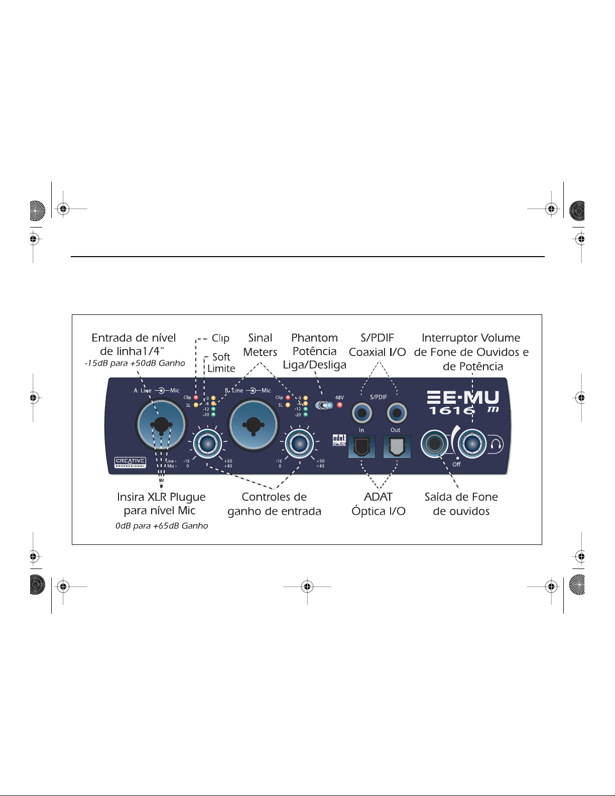
1616 GS (PG).fm Page 84 Monday, October 30, 2006 11:56 AM
7 - MicroDock & MicroDockM
O MicroDock conecta para a placa E-MU 1010 PCI através do cabo EDI. A parte frontal do MicroDock fornece duas
entradas balanceadas mic/line preamp, oito canais de entradas e saídas digitais ADAT, entrada/saída digital estéreo S/PDIF,
e uma saída de fone de ouvidos com controle de volume / interruptor de potência.
Conexões do Painel Frontal
84 - Sistema de Áudio Digital E-MU
Page 85

1616 GS (PG).fm Page 85 Monday, October 30, 2006 11:56 AM
As entradas Mono Mic/Line A & B no painel frontal podem ser utilizadas como entradas balanceadas
de microfone, entradas de guitarra hi-Z, ou entradas balanceadas de linha de nível. A tomada
Seção Preamp
Neutrik aceita microfones utilizando um conector padrão XLR ou entradas de linha de nível/hi-Z
usando um plugue de 1/4 polegada TRS.
AVISO : Alguns microfones não são compatíveis com a potência Phantom e podem danificar-se.
Verifique as especificações do seu microfone e requerimentos antes de utilizar a potência Phantom
Cada tomada RCA carrega dois canais de áudio digital. S/PDIF I/O digital pode ser utilizado para
recepção e/ou transmissão de data digital de dispositivos digitais externos tais como maquina DAT , um
Entrada e
Saída de
Áudio Digital
S/PDIF
conversor externo analógico-para-digital ou um processador de sinal externo equipado com entradas
e saídas digitais.
A saída S/PDIF pode ser configurada em modo profissional ou consumidor (sempre resolução de
24-bit). As entradas e saídas S/PDIF são compatíveis com taxas de amostragem de 44.1kHz, 48kHz,
96kHz e 192kHz.
®
ADAT
Entradas e
Saídas
Ópticas
Digitais
• Os conectores ópticos ADAT transmitem e recebem oito canais de áudio em 24-bit utilizando os
formatos ADAT tipo 1 e 2 (em 44.1kHz ou 48kHz).
• O cronômetro (word clock) contido no sinal de entrada pode ser utilizado como a fonte do mesmo.
• As entradas ópticas ADAT também podem ser modificadas para carregar S/PDIF óptico.
• ADAT também pode ser transmitido e r ecebido em 96kHz e 192kHz utilizando o padrão S/MUX.
S/MUX fornece quatro canais de áudio em 96kHz e 2 canais de áudio na taxa de amostragem de 192kHz.
A saída de fone de ouvidos alimenta fone de ouvido padrão e o controle de volume adjacente
Saída de Fone
de Ouvidos e
Controle de
Volume
determina o nível de som. Esta saída é permanentemente conectada ao Monitor de saída
encontrada no PatchMix DSP. A saída de fone de ouvidos utiliza uma versão de alta corrente das
saídas de amplificação de alta qualidade utilizadas nos outros canais. Por este motivo oferece um
sinal muito puro e de alta fidelidade que pode ser usado como uma outra saída estéreo caso você
precise.
Guia Rápido – Introdução - 85
Page 86

1616 GS (PG).fm Page 86 Monday, October 30, 2006 11:56 AM
Conexôes no Painel Traseiro
Quatro entradas balanceadas de linha de nível (24-bit) são fornecidas (estéreo 1-2). Estas podem
ser utilizadas para receber qualquer sinal de linha de nível tais como teclados, CD-player, toca-fitas,
Entradas
Analógicas de
Linha de Nível
etc. (As entradas analógicas são atribuídas às faixas de mixer no aplicativo do PatchMix DSP.) Nível
de entrada pode ser configurado para acomodar o padrão consumidor -10dBV, ou o padrão pro
áudio +4 dBu na tela de I/O encontrada na caixa de dialogo das configurações de sessão.
Ambos os cabos balanceados TRS e desbalanceados TS podem ser utilizados. Cabos balanceados
oferecem melhor imunidade contra ruídos e um nível de sinal +6dB, mas cabos de instrumento
padrão mono também funcionam bem.
86 - Sistema de Áudio Digital E-MU
Page 87

1616 GS (PG).fm Page 87 Monday, October 30, 2006 11:56 AM
Seis saídas balanceadas analógicas 24-bit de linha de nível são fornecidas (estéreo 1-3). O par de
saídas 1 é designado como Monitor de Saída e é normalmente alimentada pelo monitor de saída
do aplicativo PatchMix DSP. Todas as saídas analógicas podem livremente ser atribuídas no
Saídas
Analógicas de
Linha de Nível
aplicativo do mixer. Circuito especial (antipop) silencia as saídas analógicas quando a potência for
ligada e desligada. Como as entradas de linha analógicas, ambos os cabos balanceados TRS e
cabos desbalanceados TS podem ser utilizados. Cabos balanceados fornece melhor proteção
contra ruídos e um nível de sinal mais alto (+6dB), mas cabos de instrumento mono normais
também funcionam bem.
Nível de saída pode ser configurado para acomodar o padrão consumidor -10dBV, ou o padrão
pro áudio +4 dBu na tela de I/O, encontrada na caixa de dialogo das configurações da sessão
As entradas de plataforma giratória RCA alimentam um preamp phono RIAA que oferece
Entradas de
Plataforma
Giratória e
Ground Lug
equalização designada para aceitar cartuchos magnéticos tipo phono. As entradas da plataforma
giratória compartilham as entradas de linha 2L e 2R. Inserindo um plugue na entrada de linha 2
desconecta o preamp phono deste canal. Conecte o fio terra (ground lead) da sua plataforma
giratória para o conector Ground Lug na plataforma giratória para evitar ruídos.
Conecte o cabo de MIDI Breakout fornecido para o conector de MIDI encontrado na parte de trás
Entrada e Saída
MIDI 1 e 2
do seu MicroDock.Entradas e saídas de MIDI permitem que você possa conectar qualquer
dispositivo de MIDI tais como teclados e unidades de efeitos, controladores de bateria ou de
guitarra. Os drivers de MIDI foram instalados quando você instalou o seu software PatchMix DSP
e as portas de MIDI irão aparecer no painel de controle do sistema em ´Sounds and Audio Devices´.
Saídas
Alternativas
Estas tomadas estéreas (3.5mm) duplicam as saídas de linha de nível 1-3. Elas foram designadas
para oferecer conexão fácil com caixas acústicas amplificadas.
Conecta o MicroDock para a placa E-MU 1010 PCI utilizando cabo de computador tipo CAT 5e.
Conector EDI
O cabo fornecido com o MicroDock é especificamente protegido para prevenir emissões RF não
desejadas.
Guia Rápido – Introdução - 87
Page 88

1616 GS (PG).fm Page 88 Monday, October 30, 2006 11:56 AM
Placa-Filha Sync
8 -
A função principal do Placa-filha Sync é converter o SMPTE (LTC) para MIDI Time Code (MTC) e vice-versa. O termo “Host
MTC” refere-se ao MTC, o qual é gerado ou usado pelo aplicativo host (Cubase, etc.). O MTC é disponível também na
tomada do MIDI localizada atrás da Placa Sync.
Nota: Instalada do está do la sinc. do de do tarjeta do la de Cuando, lisiado do EL MicroDock es do en de MIDI 2. (puerto
de MIDI do EL do utilizando do está de MTC.)
O Word Clock proporciona meios padronizados de sincronização de dispositivos de áudio digital múltiplos, assim que os
dados podem ser transferidos digitalmente. Para tranferir digitalmente de um dispositivo para outro, os dois dispositivos
DEVEM estar sincronizados.
(opcional)
Conexões
Entrada e Saída
Word Clock
Entrada e Saída
SMPTE
Saída MTC
88 - Sistema de Áudio Digital E-MU
Word Clock In: Recebe Word Clock (sample clock) de um outro dispositivo digital
como um video deck digital, um gravador digital ou um mixer digital.
Word Clock Out: Envia Word Clock (sample clock) para um outro gravador digital.
O Word Clock é sempre output, sendo ele gerado por um cronômetro interno ou
transmitido através de uma entrada de Word Clock.
A entrada de SMPTE converte o código longitudinal entrante do tempo de SMPTE
(LTC) ao código do tempo de MIDI (MTC) e às passagens esta informação ao
computador de anfitrião a ser usado por um sequencer ou por uma aplicação audio
do registrador. Quando sua aplicação de computador é o "mestre", MTC gerado pela
aplicação de computador está convertido em SMPTE e emitido para fora a um outro
dispositivo de SMPTE tal como um outro registrador audio para sincronizá-lo com o
sequencer.
Esta saída transmite o código do tempo de MIDI a um outro computador ou
registrador audio. A fonte do MTC pode ser do sequencer ou do SMPTE dentro.
Page 89

1616 GS (PG).fm Page 89 Monday, October 30, 2006 11:56 AM
Obtendo Maiores Informações
A sessão ´Product Default´ é automaticamente carregada durante reinicio e possui todas as entradas e saídas configuradas
para os canais ASIO. Entretanto, você deve configurar os seus aplicativos de gravação de áudio para utilizar "E-MU ASIO".
Por favor, consulte os vários arquivos de ajuda na Internet e o manual de instruções (no CD) para informação mais detalhada
do Sistema de Áudio Digital E-MU e vários aplicativos. Veja: “Program Files -> Creative Professional -> E-MU 1616 Documents”
Suporte Técnico
Conforme a expansão do Sistema de Áudio Digital do E-MU, você pode se manter atualizado com os softwares mais
recentes e novas opções para o seu Sistema de Áudio Digital E-MU. Você pode encontrar tudo isso - e outras informações
interessantes- no site www.emu.com. Consulte o manual de instruções em formato PDF no CD fornecido para obter o
numero de telefone do suporte técnico.
Informação neste documento é sujeito a alterações sem aviso prévio e não representa compromisso por parte da E-MU. Este
manual não pode ser reproduzido de forma alguma, seja eletrônica, mecânico, incluindo fotocópia e gravação sem a permissão
escrita do E-MU Systems Inc.O software descrito neste documento foi elaborado sob acordo de licencia e pode ser utilizado ou
copiado somente de acordo com os termos da mesma. Reprodução de software é contra a lei em quaisquer mídia excetos aquelas
especificadas no acordo de licencia. Esta licencia permite ao usuário fazer uma copia do software somente para fins de backup.
E-MU é marca registrada do E-MU Systems, Inc nos Estados Unidos e/ou qualquer outro pais.
Copyright © 2006 E-MU Systems, Inc. Todos os diretos reservados.
Versão 1.82, Abril 2006
Guia Rápido – Introdução - 89
Page 90

1616 GS (PG).fm Page 90 Monday, October 30, 2006 11:56 AM
90 - Sistema de Áudio Digital E-MU
Page 91

EMUQS.fm93ページ2006年10月25日 水曜日 午後7時43分
1 -
はじめに
この度は
Creative Professional E-MU
デジタルオーディオシステム
ステムをご購入いただきまして誠にありがとうございます。この
能なようにデザインされており、あなたのコンピューターを最大
E-MU 1212M、E-MU 1616、E-MU 1616M
E-MU
デジタルオーディオシステムは論理的かつ直感的な操作が可
24bit/192kHz
というスタジオサウンドクオリティでのマルチチャ
デジタルオーディオシ
ンネルレコーディング/プレイバックが可能なオーディオプロセッシングワークステーションへと進化させます。
最低動作環境
• Intel® Pentium® 1GHz
•Intel
純正チップセットを推奨
以上のプロセッサ
• Microsoft® Windows® XP(SP2)、Windows 2000(SP4)、x64
•256 MB
•900 MB
•PCI 2.1
•XGA(1024 x 768
•
•
•
•
以上のシステムメモリ
の空き容量を持ったハードディスクドライブ(フルインストール時)
以上に準拠し
IRQ
共有のない
)以上の表示が可能なディスプレイアダプターとモニター
ソフトウェアのインストール用
CD-ROM/CD-RW
インターネットに接続可能な環境(デバイスドライバやアプリケーション等のアップデートに必要)
ミキサーやアンプ、ヘッドフォンアンプ、アクティブスピーカーシステムなど(別売り)
他のアプリケーションによっては、より高いスペックやマイクロフォンなどの別の機材が必要になるかもしれません。
1CPU
※
アクセラレータ、およびサーバー向けプロセッサ・チップセットでの動作は保証いたしかねます
※2インターネットに接続するための費用はお客様負担となります
※1
PCI
スロット1つ(
E-MU 1212M
ドライブまたは
以上
DVD-ROM
E-MU 1616Mでは2
および
ドライブ
スロット使用)
2
※
パッケージ構成
E-MU 1212M PCI E-MU 1616 PCI E-MU 1616M PCI
• E-MU 1010 PCI
• E-MU 0202 I/O
(マスタリンググレード)
•I/O
ドーターカードリボンケーブル
•ミニMIDI
• E-MU D.A.S. Software/Driver Install CD
• Production Tools Software Bundle CD
(サードパーティ製ソフトウェア)
•
オーナーズマニュアル(CDに収録)
•
クイックスタートガイド(本書)
※1サードパーティ製のソフトウェアについてのサポートは行っておりません。何卒ご了承下さい。
カード
ドーターカード
ケーブル
x2
• E-MU 1010 PCI
•MicroDock
•+48VDC AC
•EDI(E-MU Digital Interface
• MIDI
•
ヘッドフォンスプリットケーブル
• E-MU D.A.S. Software/Driver Install CD
1
※
• Production Tools Software Bundle CD
(サードパーティ製ソフトウェア)※
•
オーナーズマニュアル(CDに収録)
•
クイックスタートガイド(本書)
カード
アダプター
ブレイクアウトケーブル
)ケーブル
• E-MU 1010 PCI
•MicroDock M
•E-MU Sync
• +48VDC AC
•EDI(E-MU Digital Interface
•MIDI
ブレイクアウトケーブル
•
MIDI
ミニ
1
• E-MU D.A.S. Software/Driver Install CD
• Production Tools Software Bundle CD
(サードパーティ製ソフトウェア)※
•
オーナーズマニュアル(CDに収録)
•
クイックスタートガイド(本書)
カード
(マスタリンググレード)
ドーターカード&専用リボンケーブル
アダプター
ケーブル
)ケーブル
1
クイックスタートガイド
- 91
Page 92

EMUQS.fm94ページ2006年10月25日 水曜日 午後7時43分
安全にお使いいただくために
製品を取り扱う際には、下記の注意点を守り、製品やご自身に危険のないようにお使い下さい。
• E-MU 1010 PCI
•
さらに、
外して下さい。
• E-MU 1010 PCI
の機器に触れる際は静電気に充分ご注意下さい。静電気の帯電を防ぐためには、下記の手順に従って下さい。
•
機器の取扱いの際は、静電気を生じる不用意な行動はできるだけ避けて下さい。
•
必要な時以外は
めて下さい。
• E-MU 1010 PCI
• E-MU 1010 PCI
いない金属部分に手で触れて下さい。取り付け・取り外し作業中は、時々これを繰り返して下さい。
カードの取り付け・取り外しの際には、必ずコンピューターの電源を切って下さい。
E-MU 1010 PCI
カード、コンピューターのマザーボード、およびその他の拡張カード等が故障する原因となりますので、これら
カードの取り付け・取り外しの際には、必ずコンピューターの電源ケーブルをコンピューターから取り
E-MU 1010 PCI
カードを持つ際は、コネクターやヘッダーの金属部分には触れず、カードの端を持って下さい。
カードやその他の機器に触れる際は、先に身体の静電気を放電して下さい。放電する際はケースの塗装されて
カードに触れないようにして下さい。また保存する際には、必ず静電気防止パッケージに納
製品の詳細情報について
製品のインストールCDに収録されている、
ドライバ・アプリケーションのインストール時に標準でインストールされます。オーナーズマニュアルの閲覧には
Reader 5.0
トールの際に、必要に応じてインストールして下さい。
ソフトウェアのインストール後
ます。
以上が必要です。
PatchMix DSP
Acrobat Reader
: Windows
ミキサーの右上にある[?]マークをクリックすることで、
PDF
形式のオーナーズマニュアルを参照して下さい。オーナーズマニュアルはデバイス
はインストールCDに収録されており、デバイスドライバ・アプリケーションのインス
タスクバー上の
E-MU
アイコン( )をクリックして、
PDF
マニュアルが表示されます。
PatchMix DSP
テクニカルサポート情報
デバイスドライバ・アプリケーション、オーナーズマニュアルやチュートリアルマニュアル、製品情報、製品
社ウェブサイト
ブサイトをご参照下さい。
http://jp.creative.com/
にて随時更新される予定です。弊社カスタマーサポートへのお問い合わせは、弊社ウェ
FAQ
Adobe Acrobat
ミキサーを起動し
の更新情報は弊
92 - E-MU
デジタルオーディオシステム
Page 93

EMUQS.fm95ページ2006年10月25日 水曜日 午後7時43分
2 -
ハードウェアの取り付け
ステップ
1.
コンピューターとコンピューターに接続されている全ての周辺機器の電源を切ります。
2.
ケースの金属部分等に手を触れて、静電気を放電します。次にコンピューターと各周辺機器の電源
ケーブルを取り外します。
3.
コンピューターメーカーのマニュアルに従って、ケースカバーを外します。
4.
PCI
た
この時外したネジは後程使用しますので無くさないように気を付けて下さい。
重要
を取り外し、そのデバイスドライバ、アプリケーションを全て削除しておいて下さい。またマザー
ボードに実装されているオーディオデバイスの場合、
で無効にして下さい。これらの機能をどうしても使用したい場合、
し、その動作を確認後に、再度インストールして下さい。
ステップ
1.
空いている
ロット内に押し込みます。
2.
故障の原因になりますので、カードを無理に
ロットに挿入する前に、カードの
かを、必ず確認して下さい。カードがスロット内に適切に収まらない場合は、一度カードを抜き取り、
再度スロットに挿入して下さい。
3.
ダミーブラケットを外した際に取っておいたネジで、
1:
カードを取り付ける前に
スロットから金属製のブラケットを抜き取ります(左図参照)。
Sync
ドーターカードをインストールする際は、隣接している2つの
: E-MU
デジタルオーディオシステムのインストールの前に、既に装着済みのオーディオカード
BIOS
または
2: E-MU 1010 PCI
PCI
スロットにカードの位置を合わせ、無理な力をかけずに
カードの取り付け
PCI
PCI
コネクターがマザーボードの
スロットに押し込まないで下さい。カードを
E-MU 1010 PCI
E-MU 1212M
PCI
Windows
E-MU
PCI
スロットに正しく合っている
カードを固定します。
システムの場合、ま
スロットを使用します。
のデバイスマネージャ
システムをインストール
E-MU 1010 PCI
カードをス
PCI
クイックスタートガイド
ス
- 93
Page 94

EMUQS.fm96ページ2006年10月25日 水曜日 午後7時43分
ステップ
E-MU 0202 I/O
注意
テップ
1.
2. 0202 I/O
3.
4.
5.第3
ステップ
注意: このステップはオプションの
1.
付属のリボンケーブルで
リボンケーブルはそれぞれのカードに対して正しい向きに合わせないと、装着することができま
せん。カード上のソケットにケーブルのソケットを正しく合わせ、しっかりと接続します。
2. Sync
3.
4.
5.第3
3: E-MU 1212M用 -
ドーターカードのインストール
:
このステップは
4
へ。
付属のリボンケーブルで
参照)。リボンケーブルはそれぞれのカードに対して正しい向きに合わせないと、装着することが
できません。カード上のソケットにケーブルのソケットを正しく合わせ、しっかりと接続します。
ジで固定します。
全てが正しく安定して固定されたことを確認してから、コンピューターの筐体を閉じます。
コンピューターとコンピューターに接続されている各周辺機器の電源ケーブルを取り付け、電源
を入れます。
ドーターカードを
章ソフトウェアのインストールに進みます。
4: E-MU Sync
ドーターカードを
固定します。
全てが正しく安定して固定されたことを確認してから、コンピューターの筐体を閉じます。
コンピューターとコンピューターに接続されている各周辺機器の電源ケーブルを取り付け、電源
を入れます。
章ソフトウェアのインストールに進みます。
E-MU 1212M
E-MU 1010 PCI
ドーターカードのインストール
E-MU 1010 PCI
E-MU 1010 PCI
システム用です。
カードと
E-MU 1010 PCI
Sync
ドーターカードを購入されたユーザー用です。
カードと
カードの隣のスロットに装着し、最初に取り外したネジで
E-MU 1616/1616M
0202 I/O
カードの隣のスロットに装着し、最初に取り外したネ
Sync
ドーターカードを接続します(右図
ドーターカードを接続します(右図参照)。
システムをお使いの方はス
0202 I/O
Sync
ドーターカード
ドーターカード
94 - E-MU
デジタルオーディオシステム
Page 95

EMUQS.fm97ページ2006年10月25日 水曜日 午後7時43分
ステップ
付属する
コネクタを接続します。付属されているケーブルは標準
シールディングがされています。
注意!
い。コンピューターと
MicroDock
MicroDock
属のアダプターを接続し、
が入ります。
5: E-MU 1010 PCI
EDI
ケーブルで
: MicroDockやE-MU 1010 PCI
E-MU 1010 PCI
E-MU
のハードウェアの両方に致命的なダメージを与える恐れがあります。
に電力を供給する
は付属する
+48V DC
E-MU 1010 PCI
+48VDC
MicroDock
アダプター
カード
アダプターから電力を受けて駆動します。
カードと
カード上の
カードをコンピューター上の
前面のヘッドフォンボリュームコントロールノブを時計周りに回すことで、
MicroDock
"EDI"
を接続する
と表記された
10BaseT
ネットワークケーブル(カテゴリ5e)で、
RJ-45
Ethernet
MicroDock
コネクタと、
端子やネットワーク端子には絶対に接続しないで下さ
MicroDock
の背面の
の背面の
"+48VDC"
MicroDock
リュームコントロールノブは電源
スイッチとして機能します。
"EDI"
RF
と表記されたコネクタに付
前面のヘッドフォンボ
と表記された
放射を防ぐための
MicroDock
の電源
クイックスタートガイド
- 95
Page 96

EMUQS.fm98ページ2006年10月25日 水曜日 午後7時43分
3 -
デバイスドライバ・アプリケーションのインストール
E-MU 1010
E-MU 1010 PCI
トールする必要があります。これらをインストールするには、下記の手順に従って下さい。
Windows XP 、Windows 2000、x64
1. E-MU 1010 PCI
E-MU 1010 PCI
が
2.
デバイスドライバのインストールを促すダイアログボックスが表示されたら、[キャンセル] ボタンをクリックして下さい。
3. "E-MU Digital Audio System Software/Driver Install"
ストーラーが自動的に起動し、デバイスドライバと
インストーラーが自動的に起動しない場合は、
d:\ctrun\setup.exe(d
ストールCDを開き、[
4.
インストーラーのスプラッシュ画面が表示されたら、インストーラーの指示に従って、 まず最初にお住まいの地域(日本の場合
は[アジア])を選択し、続けてお使いの言語([日本語])を選択します。次にデバイスドライバとアプリケーションのインス
トールしたいオプションを選択して[インストール]ボタンをクリックし、セットアップを完了させて下さい。
5.
インストールの途中で「
をクリックして下さい(詳細は後述します)。
6.
再起動を促されますので、指示に従ってコンピューターを再起動して下さい。
のデバイスドライバとアプリケーションのインストール
カードを使用するには、デバイスドライバと
(その他のオペレーティングシステムはサポートされていません)
カードの取り付けが完了したら、コンピューターの電源を投入します。プラグアンドプレイによって
カードを自動認識し、デバイスドライバをインストールするよう求めてきます。
ドライブが
ctrun
]フォルダにある[
Windows
CD-ROM
ロゴテストに合格していません」という警告画面が出る場合がありますが、[続行]ボタン
Windows
ドライブの場合)と入力し、[OK]ボタンをクリックして下さい。または、イン
PatchMix DSP
のラベルのついた
PatchMix DSP
のスタートメニューから[ファイル名を指定して実行]を選択し、
setup.exe
]をダブルクリックすることでも、インストーラーが起動します。
ミキサーアプリケーションをコンピューターにインス
ミキサーアプリケーションのインストールが開始されます。
CD-ROMをCD-ROM
ドライブに挿入します。イン
Windows
デバイスドライバ、アプリケーションの完全な削除
何か問題が生じたとき、設定を初期設定に戻したいときや、最新のデバイスドライバやアプリケーションに更新するときは全ての
デバイスドライバ・アプリケーションを一度全て削除し、インストールし直すことが必要になることがあります。この際には必ず
PatchMix DSP
ているアプリケーションは削除することができません。
1.
[スタート]→[設定]→[コントロールパネル](または[スタート]→[コントロールパネル])の順にクリックし、コント
ロールパネルを開きます。
2.
[アプリケーションの追加と削除]アイコン(または[プログラムの追加と削除]アイコン)をダブルクリックします。
3.
[プログラムの追加と削除]タブをクリックします。
4.
エントリーから[
5.[InstallShield Wizard
6.
再起動する旨を聞いてきますので、指示に従ってコンピューターを再起動して下さい。
7.
現行の、または最新のデバイスドライバ、および
96 - E-MU
ミキサーアプリケーションと関連するオーディオアプリケーションを閉じてから行って下さい。削除作業時に起動し
E-MU DAS
]をクリックして[変更/削除]ボタンをクリックします。
]ダイアログボックスが表示されますので、[削除]を選択し、[次へ]ボタンをクリックします。
PatchMix DSP
ミキサーアプリケーションを再インストールして下さい
デジタルオーディオシステム
Page 97

EMUQS.fm99ページ2006年10月25日 水曜日 午後7時43分
4 - E-MU 1010 PCI
E-MU 1010 PCI
す。このパワフルなハードウェア
オーディオ処理へ振り分けることができます。
カードは
カード&インターフェース
E-MU
デジタルオーディオシステムの中枢であり、
DSP
により、ホストコンピューターの
接続端子
EDI
コネクタ
S/PDIF
デジタル入出力
同軸
®
ADAT
/
S/PDIF
光デジタル
入出力
E-MU
CPU
EDI(E-MU Digital Interface
付属の
ブルでは、
2
つの標準
を送受信します。
どとのデジタルオーディオの送受信の他、デジタルの入出力端子を装備した外部エ
フェクターなどに接続することが可能です。なお、入力データストリームに含まれ
るクロック信号は、クロックソースとして使用することができます。
また
り替える事ができます。
ションで
192kHz
重要!:
なります。
ADAT
チャンネル分の
力データに含まれるクロック信号はクロックソースとして使用することが可能です。
さらに
へと切り替えることが可能です。
96kHz
ダードを使用し、他の
重要!:
なります。
E-MU 1010 PCI
RCA
ピンジャックはそれぞれ2チャンネルのデジタルオーディオデータ
S/PDIF
同軸デジタル入出力端子は
S/PDIF
同軸デジタル入出力はプロフェッショナル/コンシューマーモードを切
44.1kHz、48kHz、96kHz
設定時にはこれらの入出力端子は無効になります。
MicroDock
光デジタル入出力端子では、
PatchMix DSP
192kHz
または
MicroDock
S/PDIF
接続時には、
24bit
オーディオ送受信する事ができます(
ミキサーアプリケーション上で
のサンプリング周波数での
ADAT
接続時には、
のもっとも強力な
パワーをより多くのソフトウェアプラグインや別の
)ケーブルで
カードと
MicroDock
同軸デジタル入力/出力ともに
のサンプリング周波数を扱うことができますが、
E-MU 1010 PCI
ADAT
タイプ1またはタイプ2フォーマットの
チャンネルを利用して必要な帯域幅を実現します。
E-MU 1010 PCI
E-DSP
チップが搭載されていま
MicroDock
間でのデータ送受信を行います。
カード上の
ADAT
カード上の
と接続します。このケー
DAT
S/PDIF
の送受信は、
A/D
や外部
24bit
S/PDIF
44.1kHz/48kHz
光デジタル入出力端子
ADAT
入出力は無効と
コンバータな
のレゾリュー
入出力は無効と
時)。入
S/MUX
スタン
8
クイックスタートガイド
- 97
Page 98

EMUQS.fm100ページ2006年10月25日 水曜日 午後7時43分
5 - E-MU 0202 I/O
E-MU 0202 I/O
備されており、
用することが可能です。この
ピンのリボンケーブルで
接続端子
ドーターカードには
MicroDock
が付属されていない
E-MU 1010 PCI
ドーターカード
24bit
バランスアナログ入力と
I/O
ドーターカードはホストコンピューターの
アナログライン
入出力
MIDI
E-MU 1212M
カードと接続されるのみで、実際に
入出力
デジタルオーディオシステムにおいてアナログ入出力、
アナログライン入力にはシンセサイザやCDプレイヤー、カセットデッキ
といったラインレベルの信号を入力することができます。この入力は
PatchMix DSP
して使用します。
アナログライン出力からはミキサー、ステレオシステムの
ワードスピーカなどのラインレベル入力へ信号を出力します。
TRS
バランスケーブルまたはTSアンバランスケーブルのどちらでも使用す
ることができます。バランスケーブルはノイズに強く、より高い信号レベ
ルになります。セッション設定ダイアログボックスの
シューマ機器で標準的な
用される
MIDI
します。付属している
DIN
換して使用します。
+4dBu
入出力端子はお使いの
コネクタを一般的にシンセサイザなどで使用される
24bit
バランスアナログ出力がそれぞれ1ペア、
PCI
スロットパネルを1つ使用しますが、内部では
PCI
スロットは使用しません。
ミキサーアプリケーションでミキサーストリップへアサイン
-10dBV
またはプロオーディオ機器で標準的に使
とを切り替えることができます。
MIDI
MIDI
アプリケーション上でアサインして使用
アダプターケーブルを使用し、カード上のミニ
Aux
I/O
タブでコン
DIN
MIDI
入出力が装
MIDI
端子を使
入力、パ
コネクタに変
40
98 - E-MU
デジタルオーディオシステム
Page 99

EMUQS.fm101ページ2006年10月25日 水曜日 午後7時43分
6 -
他の機器と接続する
クイックスタートガイド
- 99
Page 100

EMUQS.fm102ページ2006年10月25日 水曜日 午後7時43分
100 - E-MU
デジタルオーディオシステム
 Loading...