

E-MU 0404 USB Black Owner`s manual
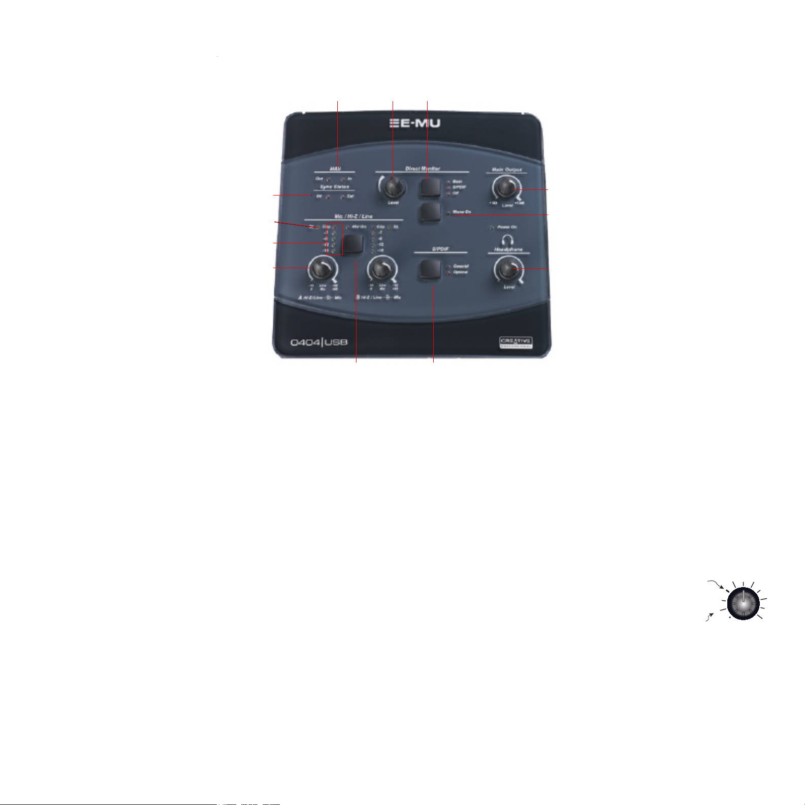
E-MU 0404 USB MAIN PANEL CONTROLS
1
6
7
2 3
Level
5
4
8
9
A
10
00
B
11
12
1. MIDI In/Out Activity Indicators
These indicators light when data is being sent or received from the MIDI port.
2. Direct Monitor Level Control
This encoder controls the mix of the input signal into the main output from
full level to off.
3. Direct Monitor Output Switch & Indicators
Turns direct monitoring on or off and allows you to send the direct monitor
signal to either the Main output or the S/PDIF output. The direct monitor
signal is a mix of all inputs.
4. Mono Switch (Direct Monitor)
When on, the left and right direct monitor channels are summed to mono.
This feature is useful when the two inputs are being used for separate
instruments.
5. Main Output Level
Controls the Main Output level.
Use Balanced cables for Professional audio level signals.
Use Unbalanced cables for Consumer audio level signals.
6. Sync Status Indicators
Indicates if the digital clock source is set to internal or external.
Select External Sync in the E-MU USB Audio control panel to select
external clock. The External LED will flash if sync is not valid.
for additional information about using digital inputs.
7. Soft Limit LEDs
The Soft Limit LEDs indicate that the signal level is being soft limited. When
enabled in the E-MU USB 2.0 Audio Control Panel, the analog soft limiters
begin to gently turn down the gain whenever the signal level goes above -12
dBFS. The soft limiters allow you to run a hotter signal without fear of
clipping.
8. Signal Level & Clip Indicators
The LED signal level indicators show the signal level for both analog inputs.
The red clip indicators momentarily remain on whenever your input level
exceeds -2.5 dBFS. With a proper signal level, the yellow -3dB LED will come
on occasionally, but the red clip LED should never light.
9. Input Level Gain Controls
The preamp level controls set the input gain from 0dB
to +65dB. The wide mark indicates the 0dB/unity
setting when using unbalanced input cables. The 0dB
mark indicates unity gain when using balanced input
cables.
0d B/Unity
(Unbalanced)
0d B/Unity
(Balanced)
0
10. 48V On Switch & LED
This switch enables +48 Volts to both XLR inputs for powering microphones
that require phantom power. The red LED indicates that phantom power is
on.
11. S/PDIF Mode
Coaxial or Optical. This button selects between coaxial cable or optical
interfaces for the S/PDIF digital interface.
+65
12. Headphone Level Control
This knob controls the volume of the Headphone output.
 Loading...