

Page 1

Short Form Manual
HASX2E-SFM-HS
02/2012
Gas Analyzers
X-STREAM X2 Series
Short Form Manual
www.EmersonProcess.com
Page 2

ESSENTIAL INSTRUCTIONS
READ THIS PAGE BEFORE PROCEEDING!
Emerson Process Management (Rosemount Analytical) designs, manufactures and
tests its products to meet many national and international standards. Because these
instruments are sophisticated technical products, you MUST properly install, use, and
maintain them to ensure they continue to operate within their normal specications.
The following instructions MUST be adhered to and integrated into your safety program
when installing, using and maintaining Emerson Process Management (Rosemount
Analytical) products. Failure to follow the proper instructions may cause any one of the
following situations to occur: Loss of life; personal injury; property damage; damage to
this instrument; and warranty invalidation.
• Read all instructions prior to installing, operating, and servicing the product.
• If you do not understand any of the instructions, contact your Emerson Process
Management (Rosemount Analytical) representative for clarication.
• Follow all warnings, cautions, and instructions marked on and supplied with the
product.
• Inform and educate your personnel in the proper installation, operation, and
maintenance of the product.
• Install your equipment as specied in the Installation Instructions of the
appropriate Instruction Manual and per applicable local and national codes.
Connect all products to the proper electrical and pressure sources.
• To ensure proper performance, use qualied personnel to install, operate, update,
program, and maintain the product.
• When replacement parts are required, ensure that qualied people use replacement
parts specied by Emerson Process Management (Rosemount Analytical).
Unauthorized parts and procedures can affect the product’s performance, place the
safe operation of your process at risk, and VOID YOUR WARRANTY. Look-alike
substitutions may result in re, electrical hazards, or improper operation.
• Ensure that all equipment doors are closed and protective covers are in place,
except when maintenance is being performed by qualied persons, to prevent
electrical shock and personal injury.
The information contained in this document is subject to change without notice.
4th edition 02/2012
Rosemount Analytical
Process Gas Analyzer Center of Excellence
Emerson Process Management GmbH & Co. OHG
Industriestrasse 1
63594 Hasselroth
Germany
T +49 6055 884 0
F +49 6055 884 209
Page 3

Short Form Manual
HASX2E-SFM-HS
02/2012
X-STREAM
Table of ConTenTs
Introduction S-1
Denitions S-1
Terms Used in This Manual .................................................. S-2
Symbols Used on and Inside the Equipment . . . . . . . . . . . . . . . . . . . . . . . . . . . . . . . . . . . . . S-3
Symbols Used in This Manual ................................................S-4
Safety Instructions S-5
Intended Use Statement..................................................... S-5
General Safety Notice / Residual Risk .......................................... S-5
Additional Literature . . . . . . . . . . . . . . . . . . . . . . . . . . . . . . . . . . . . . . . . . . . . . . . . . . . . . . . . S-5
Authorized Personnel.......................................................S-6
Installing and Connecting This Analyzer.........................................S-7
Operating and Maintaining This Analyzer........................................S-7
General Operating Notes . . . . . . . . . . . . . . . . . . . . . . . . . . . . . . . . . . . . . . . . . . . . . . . . . . . S-12
Chapter 1 Technical Description 1-1
1.1 Overview .............................................................1-2
1.1.1 Housings ............................................................1-2
1.1.2 The Front Panel / User Interface..........................................1-2
1.1.3 Interfaces............................................................1-3
1.2 Comparison of the Various X-STREAM Analyzer Models ........................1-4
1.3 X-STREAM X2GK: ½ 19 Inch Table-Top Unit .................................1-6
1.4 X-STREAM X2GP: 19 Inch Table-Top or Rackmount Design .....................1-8
1.5 X-STREAM X2XF: Field Housing With Single (XLF) or Dual (XXF) Compartment ....1-10
1.5.1 X2XF Field Housings for Installation in Hazardous Areas (Ex-Zones) ............1-13
1.6 Measurement Specications .............................................1-14
Table of contents
TOC
Chapter 2 Installation 2-1
2.1 Scope of Supply........................................................2-1
2.2 Introduction ...........................................................2-2
2.3 Technical Data .........................................................2-3
2.3.1 Common Technical Data ................................................2-3
2.3.2 Specic Technical Data .................................................2-4
2.4 Gas Conditioning .......................................................2-5
2.5 Electrical Connections ...................................................2-8
2.6 Detailed Instructions for Installation.........................................2-9
2.6.1 X-STREAM X2GK, X-STREAM X2GP ....................................2-10
2.6.2 X-STREAM XLF, X-STREAM XXF .......................................2-15
Emerson Process Management GmbH & Co. OHG TOC-1
Page 4

Short Form Manual
X-STREAM
Table of Contents
2.7 Notes On Wiring Signal Inputs and Outputs .................................2-23
2.7.1 Electrical Shielding of Cables ...........................................2-23
2.7.2 Wiring Inductive Loads ................................................2-25
2.7.3 Driving High-Current Loads.............................................2-25
2.7.4 Driving Multiple Loads.................................................2-26
HASX2E-SFM-HS
02/2012
Chapter 3 Startup 3-1
3.1 Performing a Leak Test ..................................................3-2
3.2 The User Interface......................................................3-3
3.2.1 Display..............................................................3-4
3.2.2 Status LED ..........................................................3-4
3.2.3 Keys ..............................................................3-5
3.3 Symbols Used .........................................................3-7
3.4 Software..............................................................3-8
3.4.1 Navigating and Editing .................................................3-8
3.4.2 Access Levels .......................................................3-10
3.4.3 Special Messages....................................................3-11
3.5 Powering Up .........................................................3-12
3.5.1 Boot Sequence ......................................................3-12
3.5.2 Measurement Display .................................................3-12
3.6 Selecting the Language.................................................3-13
3.7 Calibrating the Analyzer.................................................3-14
3.7.1 Preparing Calibrations.................................................3-15
3.7.2 Manual Calibration ...................................................3-17
Chapter 4 Dismounting and Disposal 4-1
4.1 Dismounting and Diposal of the Analyzer ....................................4-1
Appendix A-1
A.1 Block Diagram ........................................................A-2
A.2 Assignment of Terminals and Sockets.....................................A-15
Emerson Process Management GmbH & Co. OHGTOC-2
Page 5

Short Form Manual
HASX2E-SFM-HS
02/2012
X-STREAM
Index of fIgures
Fig. 1-1: X-STREAM Front Panel (here the X-STREAM X2GP)......................1-3
Fig. 1-2: X-STREAM X2GK .................................................1-7
Fig. 1-3: X-STREAM X2GP - Details ..........................................1-9
Fig. 1-4: X-STREAM XLF / XXF- Front Views ..................................1-11
Fig. 1-5: X-STREAM XLF - Side and Bottom View...............................1-12
Fig. 1-6: X-STREAM XLF - Power Supply and Signal Terminals ....................1-12
Fig. 2-1: X-STREAM X2 Analyzers - Scope of Supply .............................2-1
Fig. 2-2: Labelling of Gas Connectors (example).................................2-6
Fig. 2-3: Installation in Bypass Mode ..........................................2-7
Fig. 2-4: X-STREAM X2GK - Rear Panel......................................2-10
Fig. 2-5: X-STREAM X2GP - Rear Panel, Terminal Adapters, Side Brackets ..........2-11
Fig. 2-6: X-STREAM X2GK & X2GP - Dimensions...............................2-12
Fig. 2-7: Socket X1 - Analog Outputs & Digital Outputs 1-4 ........................2-13
Fig. 2-8: Power Supply Connectors ..........................................2-14
Fig. 2-9: X-STREAM XLF - Dimensions for Installation...........................2-15
Fig. 2-10: X-STREAM XXF - Dimensions for Installation...........................2-16
Fig. 2-11: X-STREAM X2XF Field Housing - Terminals, Cable Glands, Gas Connectors ..2-17
Fig. 2-12: Terminal Block X1 - Analog Outputs & Digital Outputs 1-4 (XSTA) ...........2-20
Fig. 2-13: Power Supply Connections .........................................2-21
Fig. 2-14: Shielded Signal Cable, Shielding Connected At Both Ends. ................2-23
Fig. 2-15: Shielded Signal Cable, Shielding Connected At One end...................2-23
Fig. 2-16: Signal Cable With Double Shielding, Shieldings Connected At Alternate Ends. .2-24
Fig. 2-17: Shield Connector Terminal With Cable .................................2-24
Fig. 2-18: Suppressor Diode for Inductive Loads. ................................2-25
Fig. 2-19: Driving High-Current Loads .........................................2-25
Fig. 2-20: Loads in Series...................................................2-26
Fig. 2-21: Loads in Parallel..................................................2-26
Table of contents
TOC
Fig. 3-1: Leak Testing With U-Turn Manometer ..................................3-2
Fig. 3-2: X-STREAM Front Panel .............................................3-3
Emerson Process Management GmbH & Co. OHG TOC-3
Page 6

Short Form Manual
X-STREAM
HASX2E-SFM-HS
02/2012
Index of Tables
Tab. 1-1: Gas Components and Measuring Ranges, Examples .....................1-14
Tab. 1-2: IR, UV, VIS, TCD - Measurement Performance Specifications
Tab. 1-3: Oxygen - Measurement Performance Specifications
Tab. 1-4: Trace Moisture - Measurement Performance Specifications
Tab. 1-5: Special Performance Specifications for Gas Purity Measurements
......................1-16
...............1-15
................1-17
...........1-17
Emerson Process Management GmbH & Co. OHGTOC-4
Page 7
Short Form Manual
HASX2E-SFM-HS
02/2012
X-STREAM X2
INTRODUCTION
The instruction manual contains information about the installation and startup of the XSTREAM® X2 series gas analyzers.
The manual covers several X-STREAM X2 analyzer models and so many contain informa-
tion about congurations and/or options not appliccable to your analyzer.
The installation and operation of units for use in explosive environments is NOT COVERED
in this manual!
Analyzers intended to be used in such environments are supplied with further instruction
manuals, which must be consulted in addition to the X-STREAM X2 series instruction
manual.
DEFINITIONS
The following denitions explain the use of the terms WARNING, CAUTION and NOTE in
this manual.
Safety Instructions
S
Indicates an operational or maintenance procedure, a process, a condition,
an instruction, etc.
Failure to comply may result in injury, death or permanent health risk.
Indicates an operational or maintenance procedure, a process, a condition,
an instruction, etc.
Failure to comply may result in damage to or destruction of the instrument,
or impaired performance.
NOTE!
Indicates an imperative operational procedure,
or an important condition or instruction.
Emerson Process Management GmbH & Co. OHG S-1
Page 8

X-STREAM X2
Short Form Manual
HASX2E-SFM-HS
02/2012
TERMS USED IN THIS MANUAL
Explosive Gas(es)
Flammable Gases and gas mixtures in a mixture with air within the explosive limits.
Flammable Gas(es)
Gases and gas mixtures are assigned to be
ammable if they might become ignitable
when in a mixture with air.
Infallible Containment
This term is derived from the standards of
explosion protection especially from the requirements for pressurized housings: thus an
infallible containment can be characterized
by no intended leakage into the gas paths
enabling gas to enter the inner compartment
of the analyzer housing.
Intrinsically Safe Cell (IS Cell)
Cells supplied with an intrinsically safe power
signal, approved by a Test Institute, to operate
with explosive gases.
The design ensures the IS cells remains safe
even in case of failure and explosive gases
are not ignited.
Protection Class IP66 / NEMA 4X
Both terms are used to specify conditions for
equipment to be installed outdoor.
IP stands for Ingress Protection, the rst num-
ber species protection against solid objects
(6. = dust tight) while the second number
species the degree of protection against
liquids (.6 = heavy seas).
NEMA stands for National Electrical Manuf-
acturers Association. 4X species a degree
of protection to personnel against incidental
contact with the enclosed equipment; to provide a degree of protection against falling dirt,
rain, sleet, snow, windblown dust, splashing
water, and hose-directed water; and that will
be undamaged by the external formation of
ice on the enclosure
Upper Explosion Limit (UEL)
Volume ratio of ammable gas in air above
which an explosive gas atmosphere will not
be formed: the mixture of gas and air is too
rich in fuel (decient in oxygen) to burn.
Lower Explosion Limit (LEL)
Volume ratio of ammable gas in air below
which an explosive gas atmosphere will not
be formed: the mixture of gas and air lacks
sufcient fuel (gas) to burn.
NAMUR
NAMUR is an international user association of
automation technology in process industries.
This organisation has issued experience reports and working documents, called recommendations (NE) and worksheets (NA).
Emerson Process Management GmbH & Co. OHGS-2
Page 9
Short Form Manual
HASX2E-SFM-HS
02/2012
X-STREAM X2
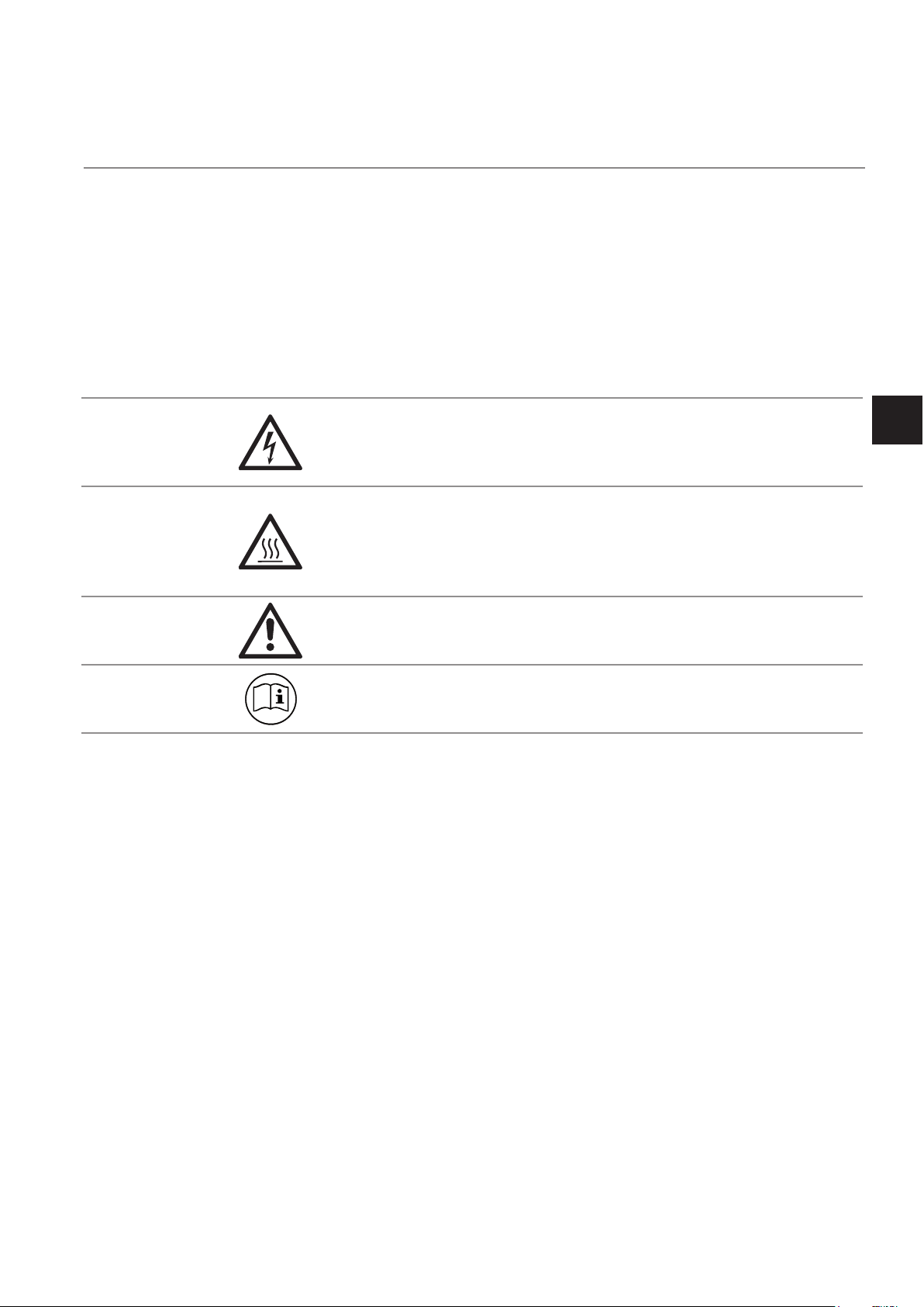
SYMBOLS USED ON AND INSIDE THE EQUIPMENT
Wherever one or more of the following symbols appear on or inside the instrument, be careful
and read the instructions given in the accompanying manuals!
Strictly observe the given warnings, instructions and information to minimize hazards!
This symbol at the instrument ... ... means
dangerous voltages may be accessible. Remo-
ving covers is permitted only, if the instrument is
disconnected from power - and even in this case
by qualied personnel only!
hot surfaces may be accessible. Removing
covers by qualied personnel is permitted only,
if the instrument is disconnected from power.
Nevertheless several surfaces may remain hot
for a limited time.
more detailled information available: see in-
struction manual before proceeding!
more detailled information available: see in-
struction manual before proceeding!
Safety Instructions
S
Emerson Process Management GmbH & Co. OHG S-3
Page 10

Short Form Manual
X-STREAM X2
HASX2E-SFM-HS
02/2012
SYMBOLS USED IN THIS MANUAL
Where one or more of the following symbols appear within this manual, carefully read the rela-
ted information and instructions!
Strictly observe the given warnings, instructions and information to minimize hazards!
This symbol used in the manual ... ... means
dangerous voltages may be exposed
hot surfaces may be exposed
possible danger of explosion
toxic substances may be present
substances harmful to health may be present
indicates notes relating to heavy instruments
electrical components may be destroyed by
electrostatic discharges
units must be disconnected from the power
source
indicates special instructions or information for
operation at low temperatures.
indicates basic conditions or procedures are
being described.
This symbol may also indicate information impor-
tant for achieving accurate measurements.
Emerson Process Management GmbH & Co. OHGS-4
Page 11

Short Form Manual
HASX2E-SFM-HS
02/2012
X-STREAM X2
SAFETY INSTRUCTIONS
INTENDED USE STATEMENT
X-STREAM series gas analyzers are intended to be used as analyzers for industrial purposes. They must not be used in medical, diagnostic or life support applications nor as
safety devices.
Using X-STREAM X2 analyzers as safety devices, requiring redundant design or SIL clas-
sication, is also not permitted.
No independent agency certications or approvals are to be implied as covering such
applications!
GENERAL SAFETY NOTICE / RESIDUAL RISK
If this equipment is used in a manner not specied in these instructions, protective sy-
stems may be impaired.
Despite of incoming goods inspections, production control, routine tests and application
of state-of-the-art measuring and test methods, an element of risk remains when operating
a gas analyzer!
Even when operated as intended and observing all applicable safety instructions some
residual risks remain, including, but not limited to, the following:
Safety Instructions
S
• An interruption of the protective earth line, e.g. in an extension cable, may result in risk
to the user.
• Live parts are accessible when operating the instrument with doors open or covers
removed.
• The emission of gases hazardous to health may even be possible when all gas connections have been correctly made.
Avoid exposure to the dangers of these residual risks by taking particular care when installing, operating, maintaining and servicing the analyzer.
ADDITIONAL LITERATURE
This manual deals with instructions on how to safely install and startup X-STREAM X2
series analyzers, intended to be operated in general purpose (safe) areas, only.
DO NOT use this manual for instruments to be installed in hazardous areas!
For comprehensive information on operating and maintain/service the instrument in a
safe manner it is MANDATORY to read all additional instruction manuals, if not provided
as printed version, see the accompanying USB stick for an electronic version (PDF)!
The following additional instruction manuals are available or referenced within this manual:
HASX2E-IM-HS X-STREAM X2 series instruction manual
HASICx-IM-H Infallible containment instruction manual
Contact your local service center or sales ofce when missing documents.
SAVE ALL INSTRUCTIONS FOR FUTURE USE!
Emerson Process Management GmbH & Co. OHG S-5
Page 12

Short Form Manual
X-STREAM X2
Safety Instructions
HASX2E-SFM-HS
02/2012
AUTHORIZED PERSONNEL
In-depth specialist knowledge is an absolutely necessary condition for working with and
on the analyzer.
Authorized personnel for installing, operating, servicing and maintaining the analyzer are
instructed and trained qualied personnel of the operating company and the manufacturer.
It is the responsibility of the operating company to
• train staff,
• observe safety regulations,
• follow the instruction manual.
Operators must
• have been trained,
• have read and understood all relevant sections of the instruction manual before
commencing work,
• know the safety mechanisms and regulations.
To avoid personal injury and loss of property, do not install, operate, maintain or service
this instrument before reading and understanding this instruction manual and receiving
appropriate training.
Emerson Process Management GmbH & Co. OHGS-6
Page 13

Short Form Manual
HASX2E-SFM-HS
02/2012
Safety Instructions
X-STREAM X2
INST ALLING AND CONNECTING THIS ANAL YZER
The following notices should be carefollowed to ensure compliance with the low voltage directive
(Europe) and other applicable regulations.
1.
Suitable grounding connections should be made at all connectors provided for this purpose.
2. All safety covers and grounding connections must be properly reinstated after maintenance
work or troubleshooting.
Safety Instructions
3. A fuse should be provided at the installation site which will completely disconnect the unit
in case of failure. Installing an isolating switch may also be benecial. In either case, these
components must be constructed to conform to recognised norms.
OPERA TING AND MAINT AINING THIS ANALYZER
On leaving our factory, this instrument confor-
med to all applicable safety directives.
In order to preserve this state of affairs, the
operator must take care to follow all the instructions and notes given in this manual and
on the unit.
Before switching on the unit, ensure that the
local nominal mains voltage corresponds to
the factory-set operational voltage of this unit.
Any interruption of the protective earth connections, whether inside or outside of the unit,
may result in exposure to the risk of electricity .
Deliberately disconnected the protective earth
is therefore strictly forbidden.
energized unit.
Fuses may only be replaced by fuses of an
identical type and with identical ratings. It is
forbidden to use repair fuses or to bypass
fuses.
Take note of all applicable regulations when
using this unit with an autotransformer or a
variable transformer.
Substances hazardous to health may escape
from the unit’s gas outlet. This may require
additional steps to be taken to guarantee the
safety of operating staff.
S
Removing covers may expose components
conducting electric current. Connectors may
also be energised. The unit should therefore
be disconnected from the power supply before
any kind of maintenance, repair or calibration
work requiring access to the inside of the unit.
Only trained personnel who are aware of
the risk involved may work on an open and
Emerson Process Management GmbH & Co. OHG S-7
Page 14
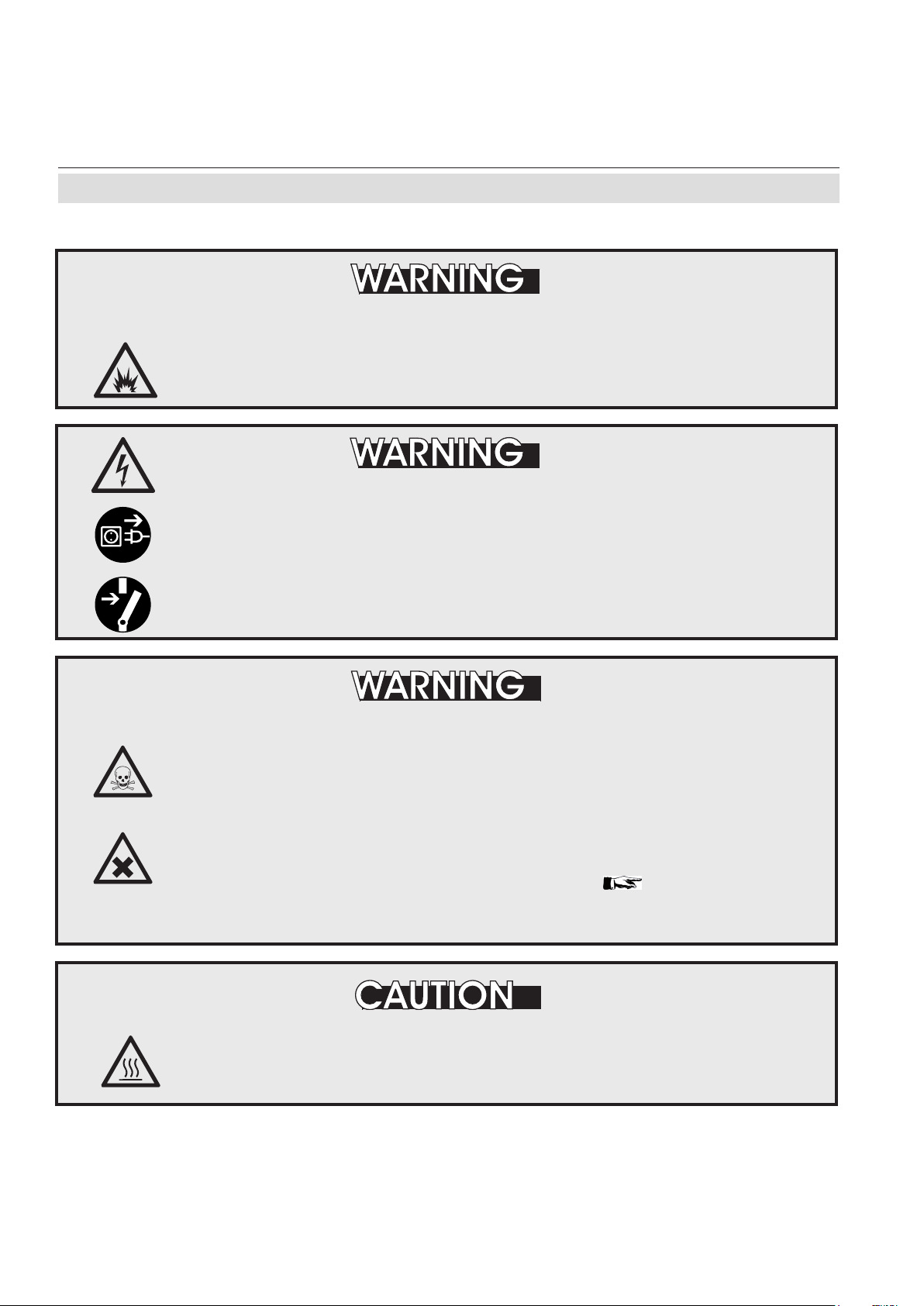
X-STREAM X2
The units described in this manual may not be used in explosive atmospheres
without additional safety measures.
Do not operate without covers secure. Do not open while energized.
Installation requires access to live parts which can cause death or serious
injury.
Short Form Manual
HASX2E-SFM-HS
02/2012
Safety Instructions
EXPLOSION HAZARD
ELECTRICAL SHOCK HAZARD
For safety and proper performace this instrument must be connected to a
properly grounded three-wire source of power.
TOXIC GASES
This unit’s exhaust may contain toxic gases such as (but not limited
to) e.g. sulfur dioxide. These gases can cause serious injuries.
Avoid inhaling exhaust gases.
Connect the exhaust pipe to a suitable ue and inspect the pipes regularly
for leaks.
All connections must be airtight to avoid leaks:
page 3-2 for
instructions on performing a leak test.
HIGH TEMPERATURES
Hot parts may be exposed when working on photometers and/or
heated components
in the unit.
Emerson Process Management GmbH & Co. OHGS-8
Page 15
Short Form Manual
HASX2E-SFM-HS
02/2012
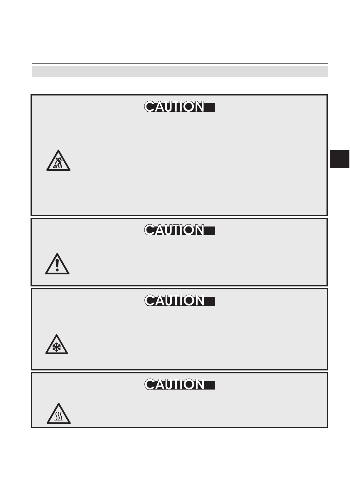
The eld housing variations intended for outside and wall mounted use
weigh between 26 kg (57 lb) and 63 kg (139 lb) depending on variation and
options installed.
X-STREAM X2
Safety Instructions
HEAVY INSTRUMENT
Safety Instructions
Two people and/or lifting equipment is required to lift and carry these
units.
Take care to use anchors and bolts specied to be used for the weight of
the units!
Take care the wall or stand the unit is intended to be installed at is solid
and stable to support the weight!
CRUSHING HAZARD
Take care of crushing hazard when closing the front door of analyzer eld
housings!
Keep out of the closing area between enclosure cover and base!
OPERATION AT LOW TEMPERATURES
When operating an instrument at temperatures below 0 °C (32 °F), do
NOT apply gas nor operate the internal pump before the warmup time has
elapsed!
S
Violation may result in condensation inside the gas paths or damaged pump
diaphragm!
HIGH TEMPERATURES
Hot parts may be exposed when working on photometers and/or heated
components in the unit.
Emerson Process Management GmbH & Co. OHG S-9
Page 16
X-STREAM X2
Safety Instructions
GASES AND PREPARATION OF GASES
GASES HAZARDOUS TO HEALTH
Follow the safety precautions for all gases (sample and span gases) and
gas cylinders.
Before opening the gas lines, they must be purged with air or neutral gas
) to avoid danger from escaping toxic, ammable, exposive or hazardous
(N
2
gases.
Short Form Manual
HASX2E-SFM-HS
02/2012
FLAMMABLE OR EXPLOSIVE GASES
When supplying ammable gases with concentrations of more than ¼ of
the lower explosion limit, we RECOMMEND implementing one or more
additional safety measures:
• purging the unit with inert gas
• stainless steel internal pipes
• ame arrestors on gas inlets and outlets
• inherently safe or failsafe measuring cells
Emerson Process Management GmbH & Co. OHGS-10
Page 17
Short Form Manual
HASX2E-SFM-HS
02/2012
Power supply
CONNECTING UNITS FOR PERMANENT INSTALLATION
Only qualied personnel following all applicable and legal regulations
may install the unit and connect it to power and signal cables. Failure to
comply may invalidate the unit’s warranty and cause exposure to the risk
of damage, injury or death.
This unit may only be installed by qualied personnel familiar with the
possible risks.
Working on units equipped with screw-type terminals for electrical
connections may require the exposure of energized components.
X-STREAM X2
Safety Instructions
Safety Instructions
S
Wall-mounted units have no power switch and are operational when
connected to a power supply . The operating company is therefore required
to have a power switch or circuit breaker (as per IEC 60947-1/-3) available
on the premises. This must be installed near the unit, easily accessible to
operators and labelled as a power cut-off for the analyzer.
HAZARD FROM WRONG SUPPLY VOLTAGE
Ensure that the local power voltage where the unit is to be installed,
corresponds to the unit’s nominal voltage as given on the name plate
label.
ADDITIONAL NOTES FOR UNITS WITH SCREW-TYPE TERMINALS
Cables for external data processing must be double-insulated against mains
power.
If this is not possible, cables must be laid in such a way as to guarantee
a clearance of at least 5 mm from power cables. This clearance must be
permanently secured (e.g. with cable ties)
Emerson Process Management GmbH & Co. OHG S-11
Page 18
Short Form Manual
X-STREAM X2
General operating notes
HASX2E-SFM-HS
02/2012
GENERAL OPERATING NOTES
HAZARD TO LIFE AND EXPLOSION HAZARD BY EXHAUST GASES
Exhaust gases may contain hydrocarbons and other toxic gases such as
carbon monoxide. Carbon monoxide is toxic.
Faulty gas connections may lead to explosion and death.
Ensure that all gas connections are connected as labelled and airtight.
• The unit must be installed in a clean and dry area protected from strong vibrations and
frost
.
• The unit must not be exposed to direct sunlight and sources of heat. Admissable ambient
temperatures (see technical details) must be adhered to.
• Gas inlets and outlets must not be interchanged.All gases must be supplied to the unit already
processed. When using this unit with corrosive sample gases, ensure that these gases do
not contain components harmful to the gas lines.
• Admissable gas pressure for sample and test gases is 1500 hPa.
• Exhaust lines must be laid inclined downwards, depressurized, protected from frost and
according to applicable regulations.
• If it is necessary to disconnect the gas lines, the unit’s gas connectors must be sealed with
PVC caps to avoid polluting the internal gas lines with condensate, dust, etc.
• To ensure electromagnetic compatibility (EMC), only shielded cables (supplied by us on re-
quest, or of equivalent standard) may be used. The customer must ensure that the shielding
is correctly tted. Shielding and terminal housing must be electrically connected; submin-D
plugs and sockets must be screwed to the unit.
• When using optional external adapters (submin-D to screw-type terminal), protection from
electromagnetic interference can no longer be guaranteed (CE compliance pursuant to EMC
guidelines). In this case the customer or operating company functions as a maker of a system
and must therefore ensure and declare compliance with EMC guidelines.
Emerson Process Management GmbH & Co. OHGS-12
Page 19

Short Form Manual
HASX2E-SFM-HS
02/2012
X-STREAM X2
Chapter 1
Technical description
The following are the main features of the Emerson Process Management X-STREAM X2
gas analyzers in brief:
• compact design with easily accessible
internal components
• customizable for a wide range of applications: different housings are avail-
able while internal construction remains
largely identical
• multilingual microprocessor-controlled
user interface with liquid crystal (LCD)
or vacuum ourescent display (VFD) to
indicate measurement value and status
messages
• units for outdoor use are optionally supplied with an impact tested front panel
• widerange power supply unit for worldwi-
1
de use without modication (
⁄2 19in units
with internal or external PSUs)
X-STREAM X2 gas analyzers can measure up to four different gas components
using any combination of the following
analyzing techniques (restrictions apply to
1
⁄219in units):
IR = non-dispersive infrared analysis
UV = ultraviolet analysis
pO
=
paramagnetic oxygen analysis
2
eO
=
electrochemical oxygen analysis
2
tO
= trace oxygen analysis
2
TCD = thermal conductivity analysis
tH
O = trace moisture measurement
2
Modied resistant measuring cells are avai-
lable for use with corrosive gases and/or
gases containing solvents.
Special congurations (e.g. intrinsically safe
or infallible measuring cells) for the analysis
of combustible gases are also available.
Technical Description
1
EXPLOSION HAZARD
X-STREAM X2 analyzers MUST NOT be used in explosive environments
(hazardous areas) without additional safety features.
This instruction manual does NOT describe the special conditions necessary
to operate gas analyzers in hazardous areas.
Please refer to the separate instruction manual, supplied with units for use
in hazardous areas.
Emerson Process Management GmbH & Co. OHG 1-1
Page 20

X-STREAM X2
1.1 Overview
1.1.1 Housings
Short Form Manual
HASX2E-SFM-HS
02/2012
1.1 Overview
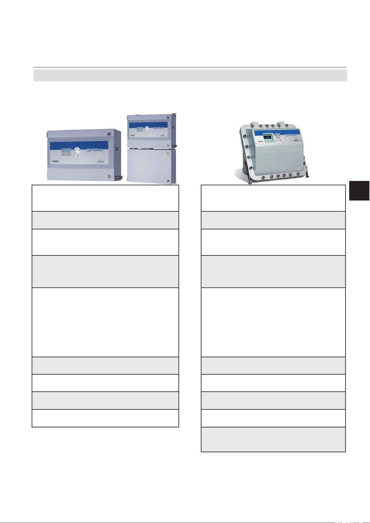
Different housings allow X-STREAM analyzers to be tailored to many different applications:
• Tabletop units in
1
⁄219in modular design,
with IP 20 protection class. Can be in-
stalled into a rack or used as a table top
instrument. Optionally featuring a handle
enabling mobile measurements at diffe-
rent sampling points.
• Tabletop and rack mountable units in 19in
modular design, with IP 20 protection
class.
1.1.2 The Front Panel / User Interface
All X-STREAM X2 gas analyzers feature an
easy-to-use LCD alphanumeric user interface, which displays measurement values,
status and error messages, and menus for
the input of parameters.
All analyzer types also feature three LEDs on
the front panel which display status information in addition to the plain text messages.
The colors of the LEDs are based on the
NAMUR NE 44 specifications. The LEDs
are activated in accordance with the NE 107
standards, and indicate “Failure”, “Function
check”, “Out of specication” and “Maintenance
request”. For further information, see
X-
STREAM X2 instruction manual, chapter 8.
• Stainless steel wall mountable field
housing with IP 66 / NEMA 4X protection
class enables outdoor use (operating
temperature -20°C to +50°C).
• Cast aluminium wall mountable eld hou-wall mountable eld hou- eld housing with IP 66 / NEMA 4X protection class
for outdoor use (operating temperature
-20 °C to +50 °C). Specially designed to
meet hazardous area certications, but
also suitable for non-hazardous locations
with requirements for robust designed
equipment.
The analyzer software is operated by means
of only six keys.
For ease of use, during operation the user can
select one of three languages for the display .
Beside the preselected languages English
and German, a third language can be selected
at time of ordering the instrument: French,
Italian, Portuguese or Spanish).
Wall-mounted units can alternatively, be tted
with a vacuum uorescent display, increasing
legibility in brighter environments.
Their display is protected with an impact tested glass
panel.
Emerson Process Management GmbH & Co. OHG1-2
Page 21

Short Form Manual
HASX2E-SFM-HS
02/2012
1.1 Overview
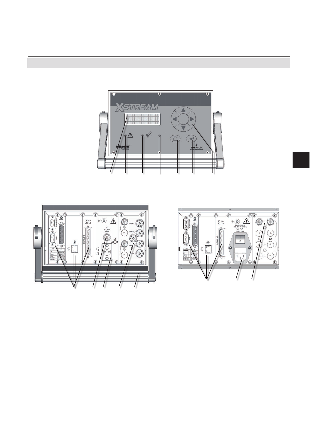
1 4x20 character
alphanumeric display
2 LED (red)
3 LED (red)
4 LED (green)
5 “Measure“ key
6 “Enter” key
7 4 keys for settings and menu navigation
1 3 4 5 6 72
Fig. 1-1: X-STREAM front panel (here the X-STREAM X2GP)
X-STREAM X2
Technical Description
1
1.1.3 Interfaces
All analyzer variations are tted with one
analog electrical output for each channel and
four status relays as standard.
As an option, further interfaces can be added:
• additional analog outputs
• additional relay outputs
• digital inputs
• Modbus Ethernet
• Modbus serial
Depending on the unit conguration, the in-
terfaces are accessible via either SubminD
connectors or screw terminals
.
Emerson Process Management GmbH & Co. OHG 1-3
Page 22
X-STREAM X2
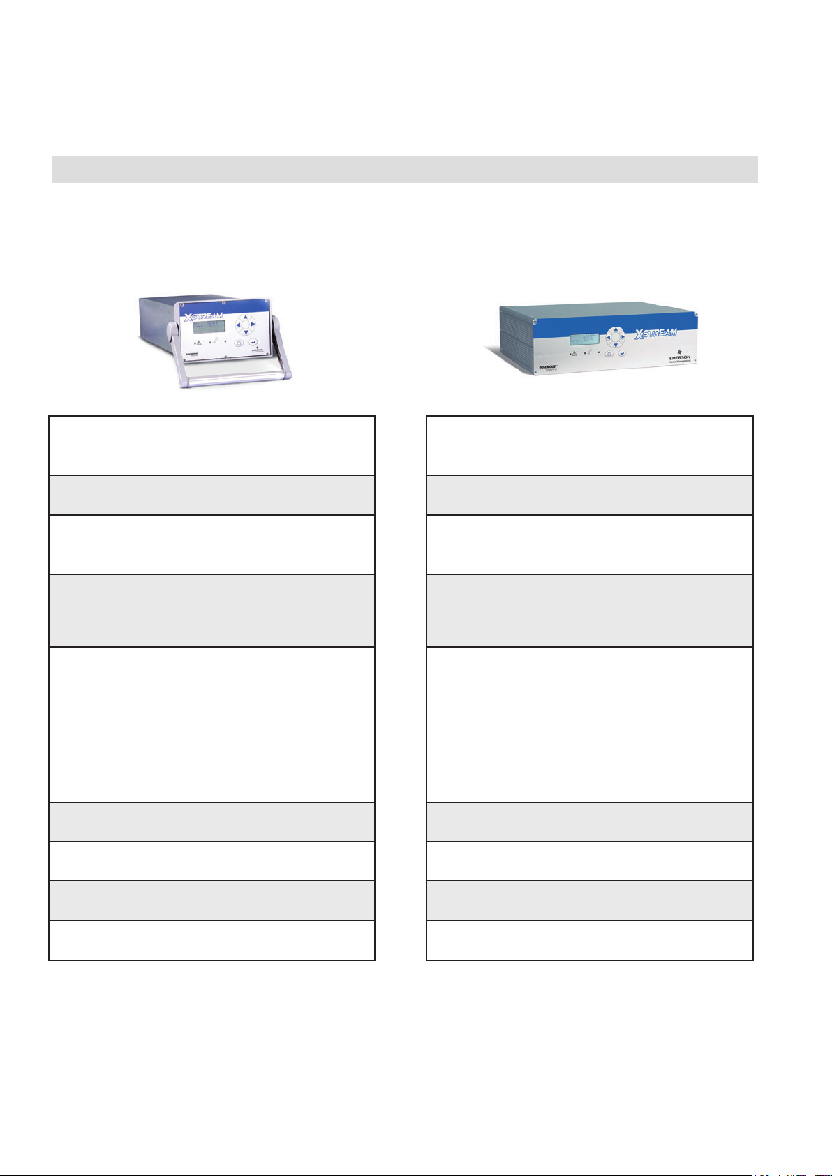
1.2 Comparison of Analyzer Models
1.2 Comparison of the Various X-STREAM Analyzer Models
X-STREAM X2GK X-STREAM X2GP
Short Form Manual
HASX2E-SFM-HS
02/2012
1
⁄219 in housing, table-top or rackmountable,
optional with carrying handle
1
⁄119 in housing, table-top or rackmountable,
protection type: IP 20
protection type: IP 20
Internal wide range power supply, or
Internal wide range power supply unit Internal wide range power supply unit Internal wide range power supply unit
24V input with external power supply unit
Max. 3 channels in many combinations
max. 8 gas connections,
including 1 optional purge gas connection
Options for gas lines: Valve block, sample gas
pump, ow sensor, pressure sensor, infallible
gas lines
Max
. 4 channels in any combination
max. 8 gas connections,
1 optional extra connection for purge gas
Options for gas lines: Flow sensor, pressu-
re sensor, heating for physical components,
sample gas pump, 1 or 2 valve blocks, infallible gas lines
1–4 analog outputs, 4 relay outputs
optional:
1 interface card with 7 digital inputs and
9 digital outputs
1 Modbus interface (serial or Ethernet)
electrical interfaces accessible via sockets on
back of unit
)
1–4 analog outputs, 4 relay outputs
optional:
1 or 2 interface cards, each with 7 digital
inputs and 9 digital outputs
1 Modbus interface (serial or Ethernet)
electrical interfaces accessible via sockets on
back of unit, optionally: screw-type terminal
adapters
(except for Ethernet)
LCD LCD LCD, optionally: vacuum uorescent display,
Operational ambient temperature:
0 °C to +50 °C (32 °F to 122 °F)
Available w/o front plate controls as module
XCC
Size: (DxHxW): max. ca. 460x128.7x213 mm
Weight: ca. 8–12 kg (17.6–26.5 lb)
Operational ambient temperature:
0 °C to +50 °C (32 °F to 122 °F)
Available w/o front plate controls as module
XCA
Size: (DxHxW): max. ca. 411x133x482 mm
Weight: ca. 11–16 kg (24–35 lb)
Emerson Process Management GmbH & Co. OHG1-4
Page 23
Short Form Manual
HASX2E-SFM-HS
02/2012
X-STREAM X2XF X-STREAM X2FD
X-STREAM X2
1.2 Comparison of Analyzer Models
Technical Description
Stainless steel wallmountable eld housing,
tection type: IP66 / NEMA 4X
ingle (XLF) or dual (XXF) compartment design
S
Max
. 4 channels in any combination
max. 8 gas connections,
1 optional extra connection for purge gas
Options for gas lines: Flow sensor, pressure
sensor, heating for physical components, sample gas pump, 1 or 2 valve blocks, infallible
gas lines
1–4 analog outputs, 4 relay outputs
optional:
1 or 2 interface cards, each with 7 digital
inputs and 9 digital outputs
1 Modbus interface (serial or Ethernet)
electrical interfaces on internal screw-type terminal adapters
impact tested front panel
operational ambient temperature:
-20 °C to +50 °C (-4 °F to 122 °F)
Models available for use in explosive environ-
ments
Size: (DxHxW): ca. 265x400 (815)x550 mm
Weight: max. ca. 26/45 kg kg (57 lb)
(except for Ethernet)
pro-
Cast aluminium wallmountable eld housing,
protection type: IP66 / NEMA 4X
Max
. 4 channels in any combination
max. 8 gas connections,
including 1 optional purge gas connection
Options for gas lines: Flow sensor, pressure sensor, heating for physical components,
sample gas pump, 1 or 2 valve blocks, infallible gas lines
1–4 analog outputs, 4 relay outputs
optional:
1 or 2 interface cards, each with 7 digital
inputs and 9 digital outputs
1 Modbus interface (serial or Ethernet)
electrical interfaces on internal screw-type terminal adapters
LCD, impact tested front panel
optionally: vacuum uorescent display
operational ambient temperature:
-20 °C to +50 °C (-4 °F to 122 °F)
Flameproof enclosure: approved for use in
explosive areas
Size: (DxHxW): max. ca. 222x512x578 mm
Weight: max. ca. 63 kg (138.5 lb)
This model is not covered by this manual!
See the separate X-STREAM Ex d manual
for hazardous area applications!
(except for Ethernet)
1
Emerson Process Management GmbH & Co. OHG 1-5
Page 24

X-STREAM X2
1.3 X-STREAM X2GK
1.3 X-STREAM X2GK: ½ 19 Inch Table-Top Unit
This compact model for general purposes
can be tted with up to three measurement
channels in various combinations. Power is
supplied by an internal wide range power sup-
ply or a separate external power supply unit.
By default the units are congured for tabletop
use. A carrying handle is optional available
which makes it easy to take the instrument to
varying sampling points. For rack mounting a
X2GK is xed by screws located at the front
panel.
Connection to power supply
AC is supplied by an IEC chassis plug with
power switch and fuse holders. The internal
wide range power supply unit enables the
analyzers to be used worldwide. Optionally
DC 24 V power is supplied via a 3-pin socket
at the rear of the unit.
Short Form Manual
HASX2E-SFM-HS
02/2012
Interfaces
Electrical connections for interface signals are
provided via submin-D and Ethernet connectors mounted on the rear panel of the device
(
Fig. 1-2 ).
Gas connections
Depending on the conguration of the unit
(number of measurement channels and serial
or parallel connection), sample and calibration
gases are fed into the unit via up to 8 tube
ttings mounted on the rear panel. Any free
tube ttings can be used for purging the de-
vice
to minimize interference from the ambient
atmosphere, or when measuring corrosive and/
or ammable gases.
Emerson Process Management GmbH & Co. OHG1-6
Page 25
Short Form Manual
HASX2E-SFM-HS
02/2012
X-STREAM X2
1.3 X-STREAM X2GK
Technical Description
1
1 3 4 5 6 72
8 13 9
8 11 1410 12
1 4x20 character alphanumeric display
2 LED (red)
3 LED (red)
4 LED (green)
5 “Measure” key
6 “Enter” key
7 4 keys for adjustment and menu selection
Fig. 1-2: X-STREAM X2GK
Emerson Process Management GmbH & Co. OHG 1-7
Note!
Figures show optional components!
8 Signal connectors (some optional)
9 Gas ttings
10 DC power input fuse
11 DC power input
12 Valve block
13 AC power input
14 Carrying handle
Page 26

X-STREAM X2
1.4 X-STREAM X2GP
1.4 X-STREAM X2GP: 19 Inch Table-Top or Rackmount Design
This model can be fitted with up to four
measurement channels in any combination.
The physical components can optionally be
encased in a cover. This area can be held at
a specic temperature of up to 60 °C to mi-
nimize interference from changes in external
temperature.
Units congured for rack mounting can be
converted for tabletop use by removing the
lateral mounting brackets and attaching the
four feet supplied as accessories.
Connection to power supply
Main power is supplied via the IEC chassis
plug mounted on the rear panel, with integrated power switch and fuse holders. The
internal wide range power supply unit enables
the analyzers to be used worldwide.
from the ambient atmosphere,
ring corrosive and/or ammable gases.
Short Form Manual
HASX2E-SFM-HS
02/2012
or
when measu-
Interfaces
Electrical connections for interface signals are
provided via submin-D connectors mounted
on the rear panel of the device ( Fig. 1-3).
For applications where screw-type terminals
are preferred, optional adapters are available,
which are mounted directly onto the submin-D
connectors.
Up to two digital I/O cards may be installed.
Gas connections
Depending on the conguration of the unit
(number of measurement channels and serial
or parallel connection), sample and calibra-
tion gases are fed into the unit via up to 8
threaded connectors mounted on the rear
panel. The conguration of the connectors is
indicated on an adhesive label located near
the connectors.
A further optional tube tting enables the
housing to be purged
to minimize interference
Emerson Process Management GmbH & Co. OHG1-8
Page 27
Short Form Manual
HASX2E-SFM-HS
02/2012
1.4 X-STREAM X2GP
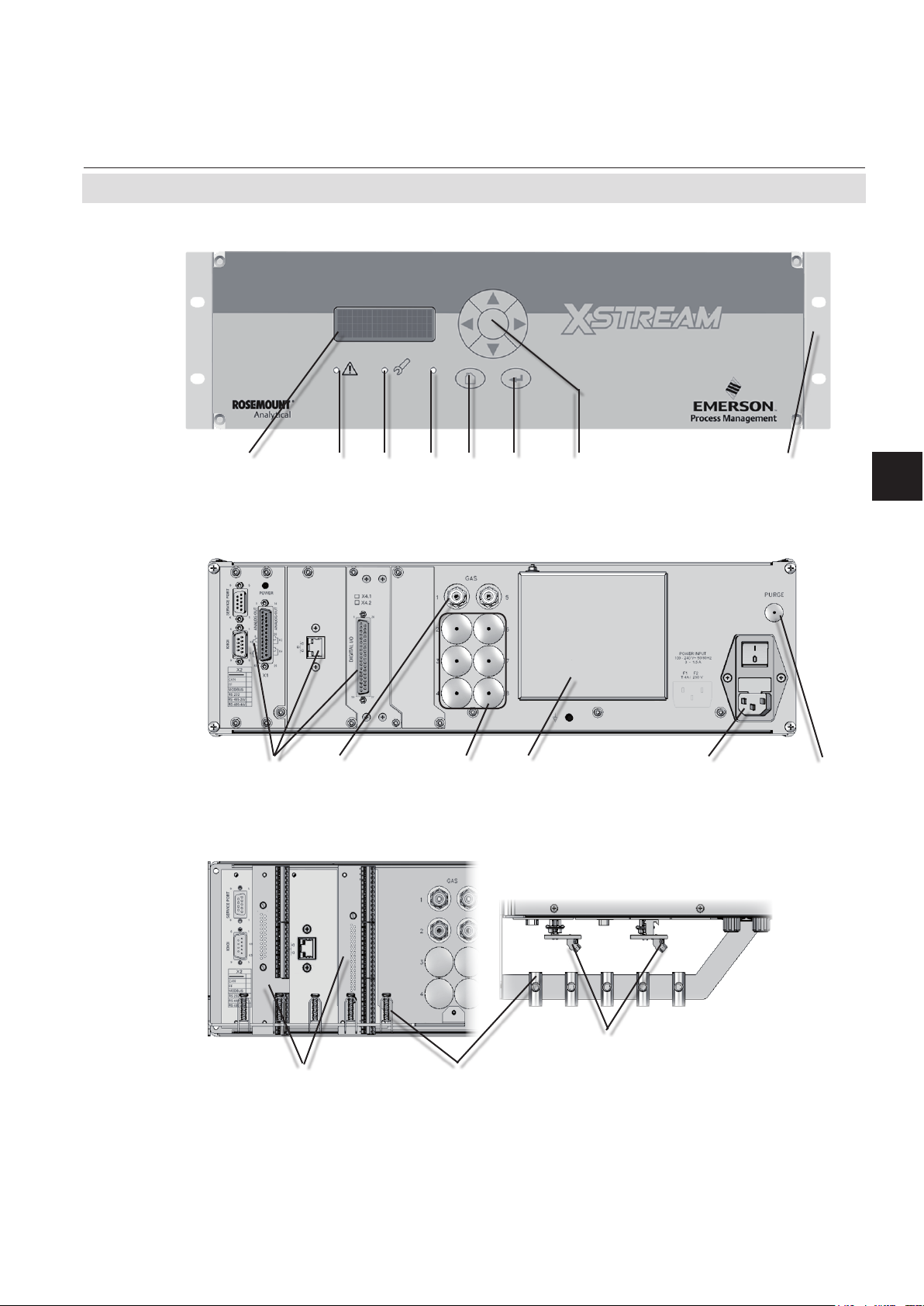
Front view
1 3 4 5 6 72 8
1 4x20 character alphanumeric display
2 LED (red)
3 LED (red)
4 LED (green)
X-STREAM X2
5 “Measure” key
6 “Enter” key
7 4 keys for adjustment and menu selection
8 Brackets for rack mounting
Technical Description
1
Rear view
15 2 6 4 3
1 Gas connectors
2 Space for additional tube ttings
3 Optional purge gas inlet
adapter
Optional
screw-type terminal
1
Fig. 1-3: X-STREAM X2GP - Details
4 Power inlet with lter, fuses & switch
5 Signal input/output connectors (some optional)
6 Cover for tO2 or eO
Strain-reliefs, top view details
1
2
1 Screw-type terminal adapters
2 Strain-reliefs
sensor
2
Emerson Process Management GmbH & Co. OHG 1-9
Page 28

Short Form Manual
X-STREAM X2
HASX2E-SFM-HS
1.5 X-STREAM X2XF Field Housings
1.5 X-STREAM X2XF: Field Housing With Single (XLF) or Dual (XXF) Compartment
02/2012
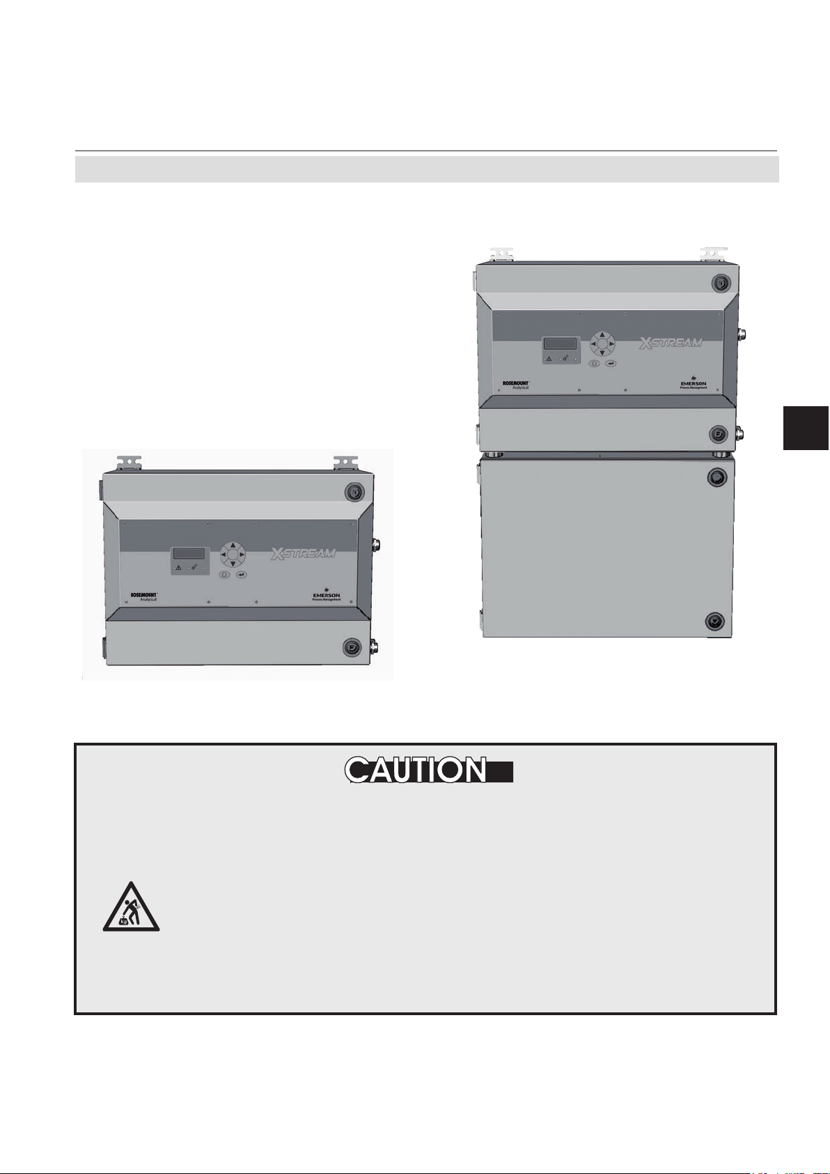
The eld housing model is conceived for
outdoor use and wall-mounting. The coated stainless steel housing has a protection
class rated IP66 / NEMA Type 4X, offering
protection against water and dust entering
the device:
IPx6: In case of occasional ooding, e.g.
heavy seas, water shall not enter in harmful
quantities
IP6x: Protection against penetration by dust.
Live or internal moving parts are completely
protected.
An X-STREAM eld housing can be tted with
up to four measurement channels in any com-
bination. The physical components can op-
tionally be encased in a cover. This separate
volume can be held at a specic temperature
of up to 60 °C to minimize interference from
changes in external temperature.
Front panel
The analyzer’s display is
covered by an impact
tested glass for enhanced protection against
breakage in harsh environments.
Interface signals
Up to two digital I/O cards may be installed.
If so, on a label nearby, they are labeled
"X4.1" for the rst I/O board, and "X4.2" for
the second.
Gas connections
Sample and calibration gases are supplied via
up to eight ttings, located at the bottom side
of the enclosure. The assignment is given on
a lable nearby.
An additional ttings enables purging the
enclosure to minimize cross interference by
ambient air, or as a protective measure when
analyzing corrosive or ammable gases.
Electrical connections
Electrical connections are provided via inter-
nal tube ttings, the cables being fed through
cable glands at the right side of the unit
Fig. 1-5). The front cover of the housing
(
swings open to the left once the fasteners
have been released.
Connection to power supply
Mains power is supplied via screw-type terminals with integrated fuse holders at the
right side of the housing, near the front. The
internal wide range power supply unit allows
the analyzers to be used worldwide.
Emerson Process Management GmbH & Co. OHG1-10
Page 29
Short Form Manual
HASX2E-SFM-HS
02/2012
1.5 X-STREAM X2XF Field Housings
Dual compartment version XXF
The dual compartment eld housing XXF not
only provides more space for additional internal components, such as signal converters,
etc, but also gives the option to separate the
physics from the electronics: Physics is installed into the lower compartment, electronics
into the upper. Also, the separation can be
gas tight, e. g. for measuring corrosive gases.
X-STREAM X2
Technical Description
1
Fig. 1-4: X-STREAM XLF / XXF- Front views
HEAVY INSTRUMENT
The X-STREAM eld housing, intended for outside and wall mounted use,
weighs approx. 26 kg/57 lb (XLF) or 45 kg/99 lb (XXF), depending on options
installed.
Two people and/or lifting equipment is required to lift and carry these units.
Take care to use anchors and bolts specied to be used for the weight of
the units!
Take care the wall or stand the unit is intended to be installed at is solid
and stable to support the weight!
Emerson Process Management GmbH & Co. OHG 1-11
Page 30
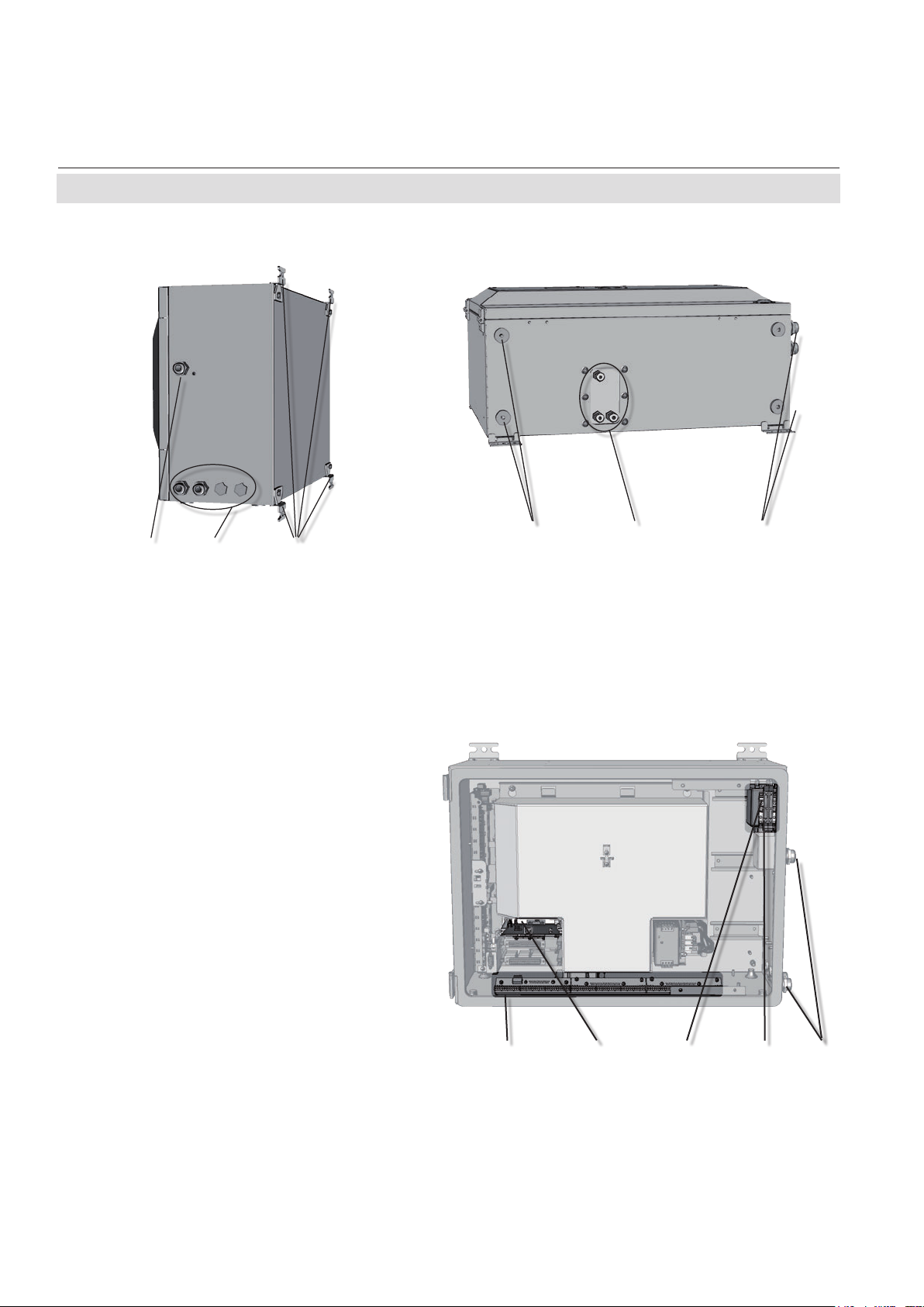
X-STREAM X2
Short Form Manual
HASX2E-SFM-HS
02/2012
1.5 X-STREAM X2XF Field Housings
21 3
1 Cable gland for power cable
2 Cable glands for signal cables
3 4 brackets for wall-mounting
4 Gas in- & outlets (max. 8)
5 Cutouts, to combine 2 housings (here closed)
Fig. 1-5: X-STREAM XLF - Side and Bottom View
Note!
In case of XXF, the terminals and
connectors are located at the upper
compartment, while physical compo-
nents and gas ttings are in the lower
compartment.
1 Screw-type terminals for signal cables
2 Power line lter
3 Cable glands
4 Power supply terminals with integrated fuses
5 Ethernet connector (option)
5 4
Note!
In case of XXF, the cable glands are located
at the upper compartment, while the gas in& outlets are at the bottom side of the lower
compartment.
Also only 2 brackets are at each compartment.
1 32 45
(shown with front panel removed)
5
Fig. 1-6: X-STREAM XLF - Power Supply and signal terminals
Emerson Process Management GmbH & Co. OHG1-12
Page 31

Short Form Manual
HASX2E-SFM-HS
02/2012
1.5 X-STREAM X2XF Field Housings
1.5.1 X2XF Field Housings for Installation in Hazardous Areas (Ex-Zones)
EXPLOSION HAZARD BY MISSING PROTECTIVE MEASURES
X-STREAM XLF and XXF models MUST not be used in explosive environments (hazardous areas) without additional safety features.
X-STREAM X2
This instruction manual does NOT describe the special conditions necessary
to operate gas analyzers in hazardous areas.
Please refer to the separate instruction manual supplied with units for use
in hazardous areas.
Special X-STREAM
variations can be used in Ex-zones 1, 2 or Div 2:
X-STREAM XLFN/XXFN:
These analyzer variations feature a protection
concept called "non-incendive" (Ex n), which
means that non-sparking and non-arcing components, installed within a protecting enclosure,
enable installation in an European Ex-zone 2
for measuring non-ammable gases. No further
measures, such as a supply of protective gas,
are necessary.
X-STREAM XLFS/XXFS:
Equipped with a simplified pressurization
system, these eld housings can be used to
measure non-ammable gases in European
Ex-zone 2. A protective gas (e.g. pressurized
air) must be supplied when operating this model.
X2XF
eld housing analyzer
Technical Description
1
X-STREAM XLFZ/XXFZ:
Equipped with a simplied pressurization system
(z-purge), these models can be used to measure
non-ammable gases in American zone Div 2.
A protective gas (e.g. pressurized air) must be
supplied when operating this model.
Please contact your local EMERSON Process
Management ofce if you require analyzers
for use in hazardous areas.
Emerson Process Management GmbH & Co. OHG 1-13
Page 32

Short Form Manual
X-STREAM X2
HASX2E-SFM-HS
02/2012
1.6 Measurement Specications
1.6 Measurement Specications
Sample gas components and measuring ranges (standard congurations)
In total, more than 60 gases are detectable, so the following table gives an overview only.
Consult with Emerson for gases / congurations not listed.
Not all data is applicable to all analyzer variations. The sample gas(es) and measuring ranges
for your specic analyzer are given by the order acknowledgement and on the analyzer's name
plate label.
Gas component Principle
Acetone
Acetone
Acetylene C
Ammonia NH
Argon Ar TCD 0–50 % 0–100 %
Carbon dioxide CO
Carbon monoxide CO IR 0–10 ppm
Chlorine Cl
Ethane C
Ethanol
Ethylene C
Helium He TCD 0–10 % 0–100 %
Hexane
Hydrogen
Hydrogen Sulde H
Hydrogen Sulde H
Methane CH
Methanol
n–Butane C
Nitrogen dioxide
Nitrogen monoxide NO IR 0–100 ppm 0–100 %
Nitrous oxide N
Oxygen O
Oxygen O
Oxygen, Trace O
Propane C
Propylene C
Sulfur dioxide SO
Sulfur dioxide SO
Sulfur hexauoride SF
Toluene
Vinyl chloride C
Water vapor
Water vapor, Trace
1
Dew point below ambient
temperature
Tab. 1-1: Gas Components and Measuring Ranges, Examples
1
1
1
1
4
1
1
1
CH
COCH
3
CH
COCH
3
2H2
3
2
2
2H6
C2H5OH IR 0–1000 ppm 0–10 %
2H4
C6H
14
H
2
S UV 0–2 % 0–10 %
2
S IR 0–10 % 0–100 %
2
4
CH3OH IR 0–1000 ppm 0–10 %
1
4H10
NO
2
O IR 0–100 ppm 0–100 %
2
2
2
2
3H8
3H6
2
2
6
C7H
8
Cl IR 0–1000 ppm 0–2 %
2H3
H2O IR 0–1000 ppm 0–8 %
1
H2O capacitive 0–100 ppm 0–3000 ppm
2
Higher concentrations
decrease sensor lifetime
3
3
UV 0–400 ppm 0–3 %
IR 0–500 ppm 0–3 %
IR 0–3 % 0–100 %
IR 0–100 ppm 0–100 %
IR 0–5 ppm
UV 0–300 ppm 0–100 %
IR 0–1000 ppm 0–100 %
IR 0–400 ppm 0–100 %
IR 0–100 ppm 0–10 %
TCD 0–1 % 0–100 %
IR 0–100 ppm 0–100 %
IR 0–800 ppm 0–100 %
UV 0–25 ppm
electrochem. 0–5 % 0–25 %
paramagn. 0–1 % 0–100 %
electrochem. 0–10 ppm 0–10 000 ppm
IR 0–1000 ppm 0–100 %
IR 0–400 ppm 0–100 %
UV 0–25 ppm
IR 0–1 % 0–100 %
IR 0–5 ppm
UV 0–300 ppm 0–5 %
3
Daily zero calibration
required for ranges below
lowest standard spec
range
Special Specs
or Conditions
Lowest
Range
5
5
3
3
3
Standard Specs
(see Tab. 1-2 – 1-4)
Lowest
Range
0–50 ppm 0–100 %
0–50 ppm 0–100 %
0–50 ppm 0–10 %
0–50 ppm 0–1 %
0–20 ppm 0–2 %
4
Special "renery" application with 0–1% H
available
in N2
2
Highest
Range
2
5
see Tab. 1-5
Emerson Process Management GmbH & Co. OHG1-14
Page 33

Short Form Manual
HASX2E-SFM-HS
02/2012
X-STREAM X2
1.6 Measurement Specications
Measurement Performance Specications
NDIR/UV/VIS Thermal Conductivity (TCD)
Detection limit (4 σ)
Linearity
1 4
Zero-point drift
Span (sensitivity) drift
Repeatability
Response time (t
Permissible gas ow 0.2–1.5 l/min. 0.2–1.5 l/min. (+ 0.1 l/min)
Inuence of gas ow
Maximum gas pressure
Inuence of pressure
– At constant temperature ≤ 0.10 % per hPa ≤ 0.10 % per hPa
– With pressure compensation
Permissible ambient temperature
Inuence of temperature
(at constant pressure)
– On zero point ≤ 1 % per 10 K ≤ 1 % per 10 K
– On span (sensitivity) ≤ 5 % (0 to +50 °C / 32 to 122 °F) ≤ 1 % per 10 K
Thermostat control
Warm-up time
1 4
1 4
1 4
1 4
) 3 4 s ≤ t90 ≤ 7 s
90
1 4
8 14
2
7
9
1 13
6 12
6
0 (-20) to +50 °C (32 (-4) to 122 °F) 0 (-20) to +50 °C (32 (-4) to 122 °F)
≤ 2 % per week ≤ 2 % per week
≤ 0.5 % per week ≤ 1 % per week
≤ 1500 hPa abs. (≤ 7 psig) ≤ 1500 hPa abs. (≤ 7 psig)
≤ 0.01 % per hPa ≤ 0.01 % per hPa
none / 60 °C (140 °F) 5 none / 60 °C (140 °F) 10
15 to 50 minutes
≤ 1 % ≤ 1 %
≤ 1 % ≤ 1 %
≤ 1 % ≤ 1 %
5
15 s ≤ t90 ≤ 30 s
≤ 0.5 % ≤ 1 %
5
approx. 50 minutes
6
11
Technical Description
1
Note! 1 psi = 68.95 hPa
1
Related to full scale
2
Related to measuring value
3
From gas analyzer inlet at gas ow of 1.0 l/min
(electronic damping = 0 s)
4
Constant pressure and temperature
5
Dependent on integrated photometer bench
6
Depending on measuring range
7
Pressure sensor is required
8
Limited to atmospheric if internal sample pump
9
Temperatures below 0 °C (-4 °F) with thermostat control only
10
Thermost. controlled sensor: 75 °C (167 °F)
11
Flow variation within ± 0.1 l/min
12
Optional thermostatically controlled box with
temperature 60 °C (140 °F), not X2GK
13
Temperature variation: ≤ 10 K per hour
14
Special conditions apply to model X2FD
Tab. 1-2: IR, UV, VIS, TCD - Measurement Performance Specications
Important Notes Concerning Measurement Specication Data
The specications given in these tables always apply to the physical measuring ranges,
as listed e.g. in the INFO-RANGES.. menu
(parameters „MinRange“ and „MaxRange“).
Scaling or zooming cannot improve analog output specications to values better than spe-
cied by the physical measuring
ranges
All performance data is veried during the manufacturing process for each unit by the following
tests:
• Linearization and sensitivity test
• Long term drift stability test
• Climate chamber test
• Cross interference test (if applicable)
Emerson Process Management GmbH & Co. OHG 1-15
Page 34

Short Form Manual
X-STREAM X2
HASX2E-SFM-HS
02/2012
1.6 Measurement Specications
Oxygen Sensors
Paramagnetic (pO
1 4
1 4
1 4
≤ 1 % ≤ 1 % ≤ 1 %
≤ 1 % ≤ 1 % ≤ 1 %
≤ 2 % per week ≤ 2 % per week ≤ 1 % per week
1 4
≤ 1 % per week ≤ 1 % per week ≤ 1 % per week
≤ 1 % ≤ 1 % ≤ 1 %
3
)
90
< 5 s approx. 12 s 20 to 80 s
Detection limit (4 σ)
Linearity
1 4
Zero-point drift
Span (sensitivity) drift
Repeatability
Response time (t
Permissible gas ow 0.2–1.5 l/min 0.2–1.5 l/min. 0.2–1.5 l/min.
Inuence of gas ow
1 4
Maximum gas pressure
Inuence of pressure
2
7 14
≤ 1500 hPa abs. (≤ 7 psig)
≤ 2 %
10
– At constant temperature ≤ 0.10 % per hPa ≤ 0.10 % per hPa ≤ 0.10 % per hPa
– With pressure compensation
6
Permissible ambient temperature
Inuence of temperature
1 12
80(-20) to +50 °C (32 (4) to 122 °F) 5 to +45 °C (41 to 113 °F) 5 to +45 °C (41 to 113 °F)
≤ 0.01 % per hPa ≤ 0.01 % per hPa ≤ 0.01 % per hPa
(at constant pressure)
– On zero point ≤ 1 % per 10 K ≤ 1 % per 10 K ≤ 1 % per 10 K
– On span (sensitivity) ≤ 1 % per 10 K ≤ 1 % per 10 K ≤ 1 % per 10 K
Thermostat control 60 °C (140 °F) 11 none none
Warm-up time Approx. 50 minutes - Approx. 50 minutes
1
Related to full scale
2
Related to measuring value
3
From gas analyzer inlet at gas ow of 1.0 l/min
(electronic damping = 0 s)
4
Constant pressure and temperature
5
Range 0–10…200 ppm: ≤ 5 % (5 to 45 °C /
41 to 113 °F)
6
Pressure sensor is required
7
Limited to atmospheric if internal sample pump
8
Temperatures below 0 °C (-4 °F) with thermostat control only
9
Thermost. controlled sensor: 35 °C (95 °F)
10
For ranges 0–5…100 % and ow 0.5…1.5 l/min
) Electrochemical (eO2) Trace (tO2)
2
≤ 2 % ≤ 2 %
13
≤ 1500 hPa abs. (≤ 7 psig) ≤ 1500 hPa abs. (≤ 7 psig)
Note! 1 psi = 68.95 hPa
11
Optional thermostatically controlled sensor with
temperature 60 °C (140 °F)
12
Temperature variation: ≤ 10 K per hour
13
No sudden pressure surge allowed
14
Special conditions apply to model X2FD
9
5
5
Note! Take care of the tO2 sensor‘s documentation, providing important calibration instructions!
Tab. 1-3: Oxygen - Standard Measurement Performance Specications
Note 1!
Not all data listed are applicable to all analyzer versions (e.g. 60 °C thermostatically controlled
box is not available for electrochemical and trace oxygen nor for
1
⁄219 in instruments).
Note 2!
For NDIR/UV/VIS measurements, take into account that
• sample gas may diffuse or be released by leakages into the analyzer enclosure
• if existent in the analyzer surroundings, the component to be measured may enter the enclosure.
Concentrations then may increase inside the enclosure. High concentrations of the component
to be measured inside the enclosure may inuence the measurement by unintended absorption,
which could cause drift of the measurement.
A remedy for this issue is to purge the housing with gas not containing the component of interest.
Emerson Process Management GmbH & Co. OHG1-16
Page 35

Short Form Manual
HASX2E-SFM-HS
02/2012
1.6 Measurement Specications
Trace Moisture (tH2O)
Measurement range
Measurement accuracy ±2 °C dew point
Repeatability 0.5 °C dew point
Response time (t
) 5 min (dry to wet)
95
Operating humidity 0 to 100 % r.h.
Sensor operating temperature -40 to +60 °C
Temperature coefcient Temperature compensated across operating temperature range
Operating pressure
Flow rate
1
If installed in series to another measurement system, e. g. IR channel
2
Special conditions apply to model X2FD
Note! Do not calibrate, see special calibration notes in the X-STREAM X2 manual!
Tab. 1-4: Trace Moisture - Standard Measurement Performance Specications
-100 to -10 °C dew point (0–100…3000 ppm)
Depending on sequential measurement system, see analyzer specication
max. 1500 hPa abs / 7 psig
2
Depending on sequential measurement system, see analyzer specication
0.2 to 1.5 Nl/min
X-STREAM X2
1
1
Note! 1 psi = 68.95 hPa
Technical Description
1
Special Performance Specications for Gas Purity Measurements (ULCO & ULCO
0–10…< 50 ppm CO
Detection limit (4 σ)
Linearity
1 2
Zero-point drift
Span (sensitivity) drift
Repeatability
1 2
Response time (t
Permissible gas ow 0.2–1.5 l/min.
Inuence of gas ow
Maximum gas pressure
Inuence of pressure
– At constant temperature ≤ 0.1 % per hPa
– With pressure compensation
Permissible ambient temperature +15 to +35 °C (59 to 95 °F) +5 to +40 °C (41 to 104 °F)
Inuence of temperature
(at constant pressure)
– On zero point < 2 % per 10 K resp. < 0.2 ppm per 10 K
– On span (sensitivity) < 2 % per 10 K resp. < 0.2 ppm per 10 K
Thermostat control none 60 °C (140 °F)
1
Related to full scale
2
Constant pressure and temperature
3
Within 24 h; daily zero calibration requested
1 2 3
90
0–5…< 50 ppm CO
1 2
< 2 %
< 1 %
< 2 % resp. < 0.2 ppm
1 2 4
< 2 % resp. < 0.2 ppm
< 2 % resp. < 0.2 ppm 9
7
)
1 2
10 11
≤ 1500 hPa abs. (≤ 7 psig)
5
8
6
< 10 s
< 2%
≤ 0.01 % per hPa
Note! 1 psi = 68.95 hPa
4
Within 24 h; daily span calibration recommended
5
Related to measuring value
6
Temperature variation: ≤ 10 K per hour
7
From gas analyzer inlet at gas ow of 1.0 l/min
2
9
9
9
9
8
Barometric pressure sensor is required
9
Whichever value is higher
10
Limited to atmospheric if internal sample pump
11
Special conditions apply to model X2FD
)
2
Tab. 1-5: Special Performance Specications for Gas Purity Measurements (ULCO & ULCO2)
Emerson Process Management GmbH & Co. OHG 1-17
Page 36

X-STREAM X2
Short Form Manual
HASX2E-SFM-HS
02/2012
Emerson Process Management GmbH & Co. OHG1-18
Page 37

Short Form Manual
HASX2E-SFM-HS
02/2012
X-STREAM X2
Chapter 2
Installation
This chapter describes the proper installation procedure for the various X-STREAM analyzer
versions.
On receipt, check the packaging and its contents thoroughly for damage.
Inform the carrier immediately of any damage to packaging or contents, and keep dama-
ged parts until clarication.
Store the instrument at a dry and clean place, considering the acceptable environmental conditions.
We recommend to keep the packaging available for future transportation, because only the ori-
ginal packaging ensures proper protection!
2.1 Scope of Supply
Compare the contents of your package with the pictures below.
Analyzers for hazardous areas need additional parts, described in the
accompanying documentation refering to hazardous area installations.
Call your local sales ofce if something is missing, and DO NOT continue
to install your analyzer, until all parts are at hand!
Installation
2
HAZARDS FROM MISSING INFORMATION
Analyzer
USB
stick
Manuals, some of which either as paper or
electronic version on USB stick:
• this short form manual
• X-STREAM X2 series manual
external power supply
with DC power cable
(X2GK, option)
Trace oxygen
cell
• infallible containment instruction manual
(if applicable to your instrument)
(if applicable)
Fig. 2-1: X-STREAM X2 Analyzers - scope of supply
Emerson Process Management GmbH & Co. OHG 2-1
Page 38

X-STREAM X2
2.2 Introduction
Before connecting the analyzer to mains power , please read the chapter on
safety warnings and the following instructions carefully.
Short Form Manual
HASX2E-SFM-HS
02/2012
2.2 Installation - Introduction
DANGER OF ELECTROCUTION
The place of installation must be clean, dry and protected against strong
vibrations and frost. Please observe the admissable operating temperatures
given in the technical data.
Units must not be subjected to direct sunlight or sources of heat.
For outdoor installation it is recommended to install the unit in a cabinet.
It should at least be protected against rainfall.
In order to comply with regulations on elec-
tromagnetic compatibility, it is recommended
to use only shielded cables which can be
supplied by Emerson Process Management.
The customer must ensure that the shielding
is correctly connected to the signal cable plug
housing. Submin-d plugs and sockets must
be screwed to the analyzer.
The use of external submin-d to screw-type
terminal adapters affects electromagnetic
compatibility. In such a case the customer
must take appropriate measures to comply
with the regulations, and must declare conformity when this is legally required (e.g.
European EMC guidelines).
Emerson Process Management GmbH & Co. OHG2-2
Page 39

Short Form Manual
HASX2E-SFM-HS
02/2012
2.3 Installation - Technical Data
2.3 Technical Data
Before intending to start to install the analyzer, verify the site of installation meets the
specications, given in the following sections!
2.3.1 Common Technical Data
Site of installation
Humidity
(non-condensing)
Degree of pollution 2
Installation category II
Elevation 0 to 2000 m (6560 ft) above sea level
Ambient atmosphere
Analyzer Certications
Electrical safety
< 90 % RH at +20 °C (68 °F)
< 70 % RH at +40 °C (104 °F)
Units may not be operated in corrosive,
ammable or explosive environments
without additional safety measures.
X-STREAM X2
Installation
2
CAN / USA
Europe
Electromagnetic
compatibility
Europe CE, based on EN 61326
Australia C-Tick
others NAMUR
CSA-C/US, based on CAN/CSA-C22.2 No.
61010-1-04 / UL 61010-1, 2nd edition
CE, based on EN 61010-1
Emerson Process Management GmbH & Co. OHG 2-3
Page 40

X-STREAM X2
2.3 Installation - Technical Data
2.3.2 Specic Technical Data
Temperatures
operational
Short Form Manual
HASX2E-SFM-HS
X2GK X2GP X2XF
0…+50 °C
32…122 °F
0 (-20)…+50 °C
32 (-4)…122 °F
02/2012
storage
Weight, max
IP or Type rating
-20…+70 °C
-4…-158 °F
8…12 kg
17.6…26.5 lb
12…16 kg
26.5…35.3 lb
IP 20
indoor use,
protected against dripping water and
direct sun light
-20…+70 °C
-4…158 °F
XLF: 25 kg / 55.1 lb
XXF: 45 kg / 99.2 lb
IP 66 / Type 4X
outdoor use ,
protected against
direct sun light
Gas connections
max number 8
max for purging
(separate / incl.)
2 incl.
1 separate,
1 incl.
1 separate,
1 incl.
material PVDF; stainless steel (opt.) stainless steel
1
sizes 6/4 mm;
Power supply unit
external
(option)
⁄4"
wide range,
internal
Power supply
nominal voltage 24 V
100–240 V
50 / 60 Hz
voltage range
10…
30 V
85–264 V
47–63 Hz
nominal input current
standard, max 2.5 A 1.3–0.7 A 1.3–0.7 A
w/ temperature control,
max
Power input fuses
AC 230 V
T 3.15 A
5x20 mm
n.a. 3–1.5 A
AC 230 V
T 4 A
5x20 mm
AC 230 V
T 4 A
5x20 mm
Emerson Process Management GmbH & Co. OHG2-4
XLF: 1.3–0.7 A
XXF: 1.5–0.8 A
XLF: 3–1.5 A
XXF: 5.5–3 A
AC 230 V
T 6.3 A
5x20 mm
Page 41

Short Form Manual
HASX2E-SFM-HS
02/2012
2.4 Gas Conditioning
X-STREAM X2
2.4 Installation - Gas Conditioning
In order to ensure trouble-free operation, spe-
cial attention must be paid to the preparation
of the gases:
All gases must be conditioned
before supplying to the analyzer ,
to be
• dry,
• free of dust and
• free of any aggressive com-
ponents which may damage
the gas lines (e.g. by corrosion or solvents) .
Case purge option
The purge medium (e.g. to minimize CO
interference or for enhanced safety when
measuring corrosive or poisonous gases)
• must be dry, clean and free of corrosives or components containing solvents.
• has to be free of components to be
measured, to minimize cross interferences.
Its temperature must correspond to the ambient temperature of the analyzer , but be at
least within the range 20…35 °C (68…95 °F).
Pressure and gas ow must remain within
the values given in the
„Measurement
Specications“ section within this manual.
If moisture cannot be avoided, it is necessary
to ensure that the dew point of the gases is at
least 10 °C (18 °F) below the ambient temperature to avoid condensate in the gas lines.
Hints for selected gases
• Calibration gases for CO and NO need
to be moistured by supplying them via a
Installation
cooler.
2
Open reference option
I
2
n some cases, the measuring cell has an open
reference side, to be supplied with nitrogen.
This nitrogen
• at least should be of quality 5.0, which
means nitrogen of purity ≥ 99.999 %.
If such gas is not available, the substitute
• must be dry, clean and free of corrosives or components containing solvents.
• has to be free of components to be
measured, to minimize cross interferences.
In any case, the gas temperature must correspond to the ambient temperature of the
analyzer, but at least be within the range
20…35 °C (68…95 °F).
Pressure and gas ow must remain within
the values given in the „Measurement
Specications“ section within this manual.
Perform a calibration each time
the source of this gas (e. g.
bottle) has changed!
Emerson Process Management GmbH & Co. OHG 2-5
Page 42

X-STREAM X2
Take care that all external gas pipes are connected in the described way
and that they are gastight to avoid leakages!
Faulty connected gas pipes lead to explosion hazard or even to mortal
danger!
Don‘t take a breath of the emissions! Emissions may contain hydrocarbons
or other toxic components (e.g. carbon monoxide)! Carbon monoxide may
cause headache, sickness, unconsciousness and death.
Short Form Manual
HASX2E-SFM-HS
02/2012
2.4 Installation - Gas Preparation
TOXIC GAS HAZARDS
Do not confuse gas inlets and outlets. All gases supplied must be prepared
beforehand. When supplying aggressive gases, ensure that the gas lines
are not damaged.
Max. admissable pressure: 1500 hPa!
Exhaust lines must be installed to incline downwards and be unpressurized
and protected against frost, and conform to legal requirements.
The number of gas connections and their
congration may vary according to analyzer
version and installed options.
All gas connectors are labelled and can be
found on the
analyzer’s rear panel (X-STREAM X2GP,
•
X-STREAM X2GK)
• underside of the analyzer (X-STREAM eld
housings)
Should it be necessary to open the gas lines,
the gas connectors should be sealed with
PVC caps to prevent pollution by moisture,
dust, etc.
Fig. 2-2: Labelling of gas connectors (example)
Emerson Process Management GmbH & Co. OHG2-6
Page 43

Short Form Manual
HASX2E-SFM-HS
02/2012
X-STREAM X2
2.4 Installation - Gas Preparation
The analyzer should be mounted close to the
sample gas source to minimize transport time.
A sample gas pump can be used to reduce the
reaction time; this requires that the analyzer
be operated in bypass mode or tted with
Pressure control valve
Filter
Sample gas pump
Fig. 2-3: Installation in bypass mode
a pressure control valve to protect against
excessive gas ow and pressure (Fig 1-2).
Exhaust
Analyzer
Flow sensor
Exhaust
Installation
2
Emerson Process Management GmbH & Co. OHG 2-7
Page 44

X-STREAM X2
2.5 Installation - Electrical Connections
2.5 Electrical Connections
Only qualied personnel, observing all applicable technical and legal
requirements, may install these devices and connect power and signal
cables.
Failure to comply may render the guarantee void and cause exposure to
risk of damage, injury or death.
The devices may only be installed by personnel who are aware of the
possible risks. Working on units with screw-type terminals for electrical
connections may require exposure to energized components.
Short Form Manual
HASX2E-SFM-HS
02/2012
ELECTRICAL SHOCK HAZARD
Wall-mounted X-STREAM analyzers are not tted with power switches and
are operational as soon as they are connected to a power supply.
For these analyzers a switch or circuit breaker (IEC 60947-1/-3) must be
installed on the premises. The switch or breaker must be located near the
analyzer, easily accessible and labelled as a power supply cut-off for the
analyzer.
Units with screw-type terminals must be de-energized by unplugging it or
operating the separate cut-off switch or circuit breaker when working on
the power connections.
T o avoid the risk of electrocution, all units must be earthed. For this reason,
the power cable with a protective earth wire must be used.
Any break in the earth wire inside or outside the unit may cause exposure
to the risk of electrocution and is therefore prohibited.
Emerson Process Management GmbH & Co. OHG2-8
Page 45

Short Form Manual
HASX2E-SFM-HS
02/2012
2.6 Detailed Instructions for Installation
2.6 Detailed Instructions for Installation
Important note for X-STREAM X2FD!
Due to the special conditions which must be observed when installing units in EX zones, the
installation of the ameproof X-STREAM X2FD version is described in a separate instruction
manual HASXMDE-IM-EX.
Even if you do not install your X-STREAM X2FD in an EX zone, refer to this separate manual for
installation instructions.
X-STREAM X2
Installation
Important note for analyzers measuring traces of oxygen!
The electrochemical sensor used for this measurement is a consumable. Remaining lifetime
counts down when the sensor is in contact with oxygen.
For above reasons, concerned analyzers are shipped with the sensor as extra item in a sealed bag!
The sensor must be installed before analyzer startup, according the instructions shipped with
the sensor!
Installation instructions: X-STREAM X2GK, X2GP page 2-10
X-STREAM X2XF Field housings page 2-15
Notes for wiring signal inputs and outputs page 2-23
2
Emerson Process Management GmbH & Co. OHG 2-9
Page 46

X-STREAM X2
2.6 Installation - X-STREAM X2GK, X-STREAM X2GP
2.6.1 X-STREAM X2GK, X-STREAM X2GP
Short Form Manual
HASX2E-SFM-HS
02/2012
Plugs and sockets required for the electrical
connections are on the rear panel of the units
( Fig. 2-4 & Fig. 2-5 ).
X-STREAM X2GP analyzers provide an internal wide range power supply for worldwide
use.
X-STREAM X2GK analyzers are powered by
an internal wide range power supply for world-
wide use, or by an external DC 24 V power
supply unit, optionally supplied with the unit.
Digital in- /
Analog outputs / relay
outputs
Service interface
outputs
Gas inlets
Gas outlets
If an external PSU is not included in delivery ,
another unit can be used instead, provided it
conforms to the specications given by the
X-STREAM X2 instruction manual.
X-STREAM X2GK / X2GP analyzers should
be operated in a horizontal position.
Six screws at the front panel enable to install
X2GK models into a rack. The external PSU
is optionally available for rack mounting, too.
X2GP can be installed into a rack by adding
two optional brackets to the left and right hand
side of the instrument.
HAZARD BY RACK INSTALLATION
The front panel and its screws
are not designed to carry the
weight of the instrument!
with fuses
( RS 232 /
Modbus 485)
Serial interface
Fig. 2-4: X-STREAM X2GK - rear panel
RJ45 ethernet
connectors
AC Power inlet
Support the instrument, when
installed into a rack!
Disregarding may cause personal injury and damaged
equipment.
Alternative
DC Power inlet
and separate
fuse
Emerson Process Management GmbH & Co. OHG2-10
Page 47

Short Form Manual
HASX2E-SFM-HS
02/2012
2.6 Installation - X-STREAM X2GK, X-STREAM X2GP
Analog outputs / NA-
Services interface
RJ45 ethernet connectors
MUR status relays
Digital inputs /
outputs
Gas inlets
Gas outlets
2
sensor
2
or tO
Cover for eO
X-STREAM X2
(optional)
Purge gas inlet
Installation
2
4 screw holes for rack mounting
(7.5 x 10.5 mm / 0.29" x 0.41")
Fuses
Power in
Modbus 485)
Modbus interface
(RS 485 / RS 232 /
Fig. 2-5: X-STREAM X2GP - rear panel, shown with options
Strain reliefs and
for signal cables
shielding contacts
Power switch
The number and congration of the gas inlets and outlets vary from model to model and are
indicated on the notice on the rear of the instrument.
To simplify installation, we recommend labelling the gas lines as in the Figres above (In1, Out1,
…, In4, Out4 or 1, 2, … 7, 8) .This avoids confusion in case the analyzer ever has to be dis-
connected.
X2GK X2GP
Gas connections
max number 8 8
max for purging (incl. / separate) 2 incl. 1 incl. & 1 separate
material PVDF; stainless steel (opt.)
1
sizes 6/4 mm;
⁄4"
Emerson Process Management GmbH & Co. OHG 2-11
Page 48

X-STREAM X2
2.6 Installation - X-STREAM X2GK, X-STREAM X2GP
X2GK
X2GP
Short Form Manual
HASX2E-SFM-HS
02/2012
Height of rear panel
cover for
tO
cell: 10 mm [0.39]
2
eO
cell: 36 mm [1.42]
2
HAZARD BY RACK INSTALLATION
The front panel and its screws
are not designed to carry the
weight of the instrument!
Support the instrument, when
installed into a rack!
Disregarding may cause personal injury and damaged
equipment.
Fig. 2-6: X-STREAM X2GK & X2GP - dimensions
approx. values
in mm [in]
Strain relief bracket, detail
(model with clamping adapters)
Emerson Process Management GmbH & Co. OHG2-12
Page 49

Short Form Manual
HASX2E-SFM-HS
02/2012
X-STREAM X2
2.6 Installation - X-STREAM X2GK, X-STREAM X2GP
Signal inputs and outputs (basic conguration)
The number of signal outputs actually available varies according to the unit’s conguration.
Analog signals
Relay outputs
Analog signals and relay outputs are located on a shared 25-pin submin socket X1,
or on an optional terminals adaptor XSTA (
page 2-20; not for X2GK).
Specication of analog signal outputs: 4(0)–20 mA; burden: RB ≤ 500 Ω
Specication of relay outputs 1–4:
Electrical specication:
Dry relay change-over contacts can be used as
NO or NC.
max. 30 VDC, 1 A, 30 W
Installation
2
Note!
• Consider the installation notes in section 2.7.
• Technical data and installation information for further available interfaces are given in the
X-STREAM X2 instruction manual. Connector layouts are part of the appendix of this manual.
Signal Pin
Channel 1, (+) 4 (0) - 20 mA 1
Channel 2, (+) 4 (0) - 20 mA 2
Channel 3, (+) 4 (0) - 20 mA 3
Analog
outputs
Channel 4, (+) 4 (0) - 20 mA 4
unused 5
unused 6
unused 7
Output1 (Failure) NC 8
Output1 (Failure) NO 9
Output1 (Failure) COM 10
Output3 (Off spec) NC 11
Output3 (Off spec) NO 12
Relay contacts
(Status signals)
Output3 (Off spec) COM 13
Pin Signal
14 Channel 1, GND
15 Channel 2, GND
16 Channel 3, GND
17 Channel 4, GND
18 unused
19 unused
20 Output2 (Maintenance request) NC
21 Output2 (Maintenance request) NO
22 Output2 (Maintenance request) COM
23 Output4 (Function check) NC
24 Output4 (Function check) NO
25 Output4 (Function check) COM
Analog
Relay contacts
Note!
Congration of relay contacts
as per standard factory setting (NAMUR
status signals)
outputs
(Status signals)
Fig. 2-7: Socket X1 - Analog Outputs & Digital Outputs 1-4
Emerson Process Management GmbH & Co. OHG 2-13
Page 50

X-STREAM X2
2.6 Installation - X-STREAM X2GK, X-STREAM X2GP
Power supply
X-STREAM X2GK and X2GP
AC power is supplied to the unit by means of
a three-pin IEC connector on the rear panel
of the instrument.
Short Form Manual
HASX2E-SFM-HS
02/2012
Optional DC Supply for X-STREAM X2GK
24 VDC is supplied to the unit by means of a
three-pin XLR connector on the rear panel of
the instrument.
Depending on the order, the following is supplied as an accessory: either
• an external power supply unit which can
be connected directly to the analyzer using
the supplied cable
or
• a connector which can be used with a cab-
le and PSU as specied by the customer.
Note the conguration of the connector´s pins
(
Fig. 2-8).
Details of any PSUs supplied with the unit are
given by the X-STREAM instruction manual.
3
X2GP AC connectors X2GK
DC connector X2GK
Fig. 2-8: Power supply connectors
Emerson Process Management GmbH & Co. OHG2-14
Page 51
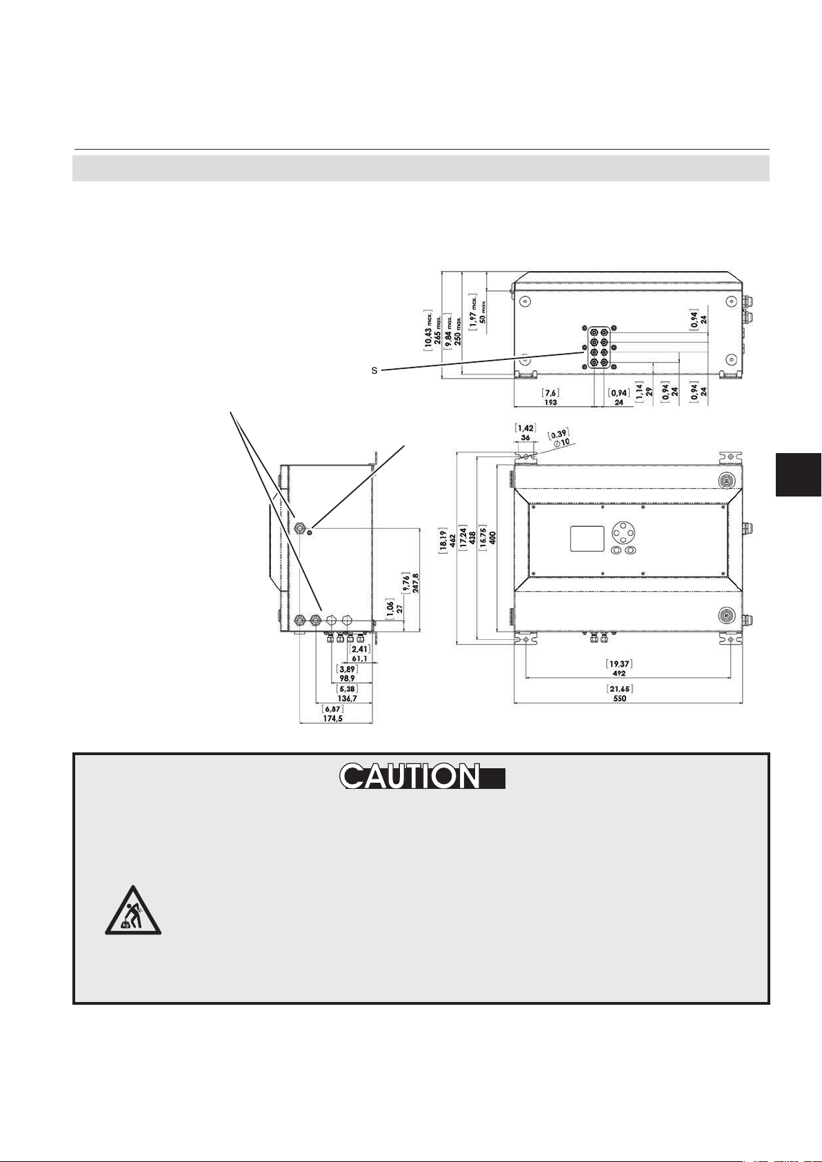
Short Form Manual
HASX2E-SFM-HS
02/2012
2.6 Installation - X-STREAM X2XF Field Housings
2.6.2 X-STREAM X2XF
X-STREAM X2
Fitted with four eyebolts and featuring IP66/
Type 4X protection, the X-STREAM XE eld
Gas ttings
Cable glands
Note!
Take care to reserve space at the
right side of the instrument for laying
the cables!
Connector
for potential
equalization
housing can be mounted in the open air on a
wall or frame with no extra work.
Installation
2
All dimensions in mm
[inches in brackets]
Fig. 2-9: X-STREAM XLF - dimensions for installation
HEAVY INSTRUMENT
X-STREAM eld housings, intended to be wall mounted or outdoor installed,
weigh up to 45 kg (99 lbs), depending on the chosen options!
Use two persons and/or suitable tools for transportation and lifting these
instruments!
Take care to use anchors and bolts specied to be used for the weight of
the instruments!
Assure that the wall / device for installation is sufciently attached and
stable to carry the instrument!
Emerson Process Management GmbH & Co. OHG 2-15
Page 52

X-STREAM X2
2.6 Installation - X-STREAM X2XF Field Housings
Note!
Take care to reserve space
at the right side of the instrument for laying the cables!
Connector
for potential
equalization
Short Form Manual
HASX2E-SFM-HS
02/2012
Gas ttings
All dimensions in mm
[inches in brackets]
Cable glands
Fig. 2-10: X-STREAM XXF - dimensions for installation
Emerson Process Management GmbH & Co. OHG2-16
Page 53
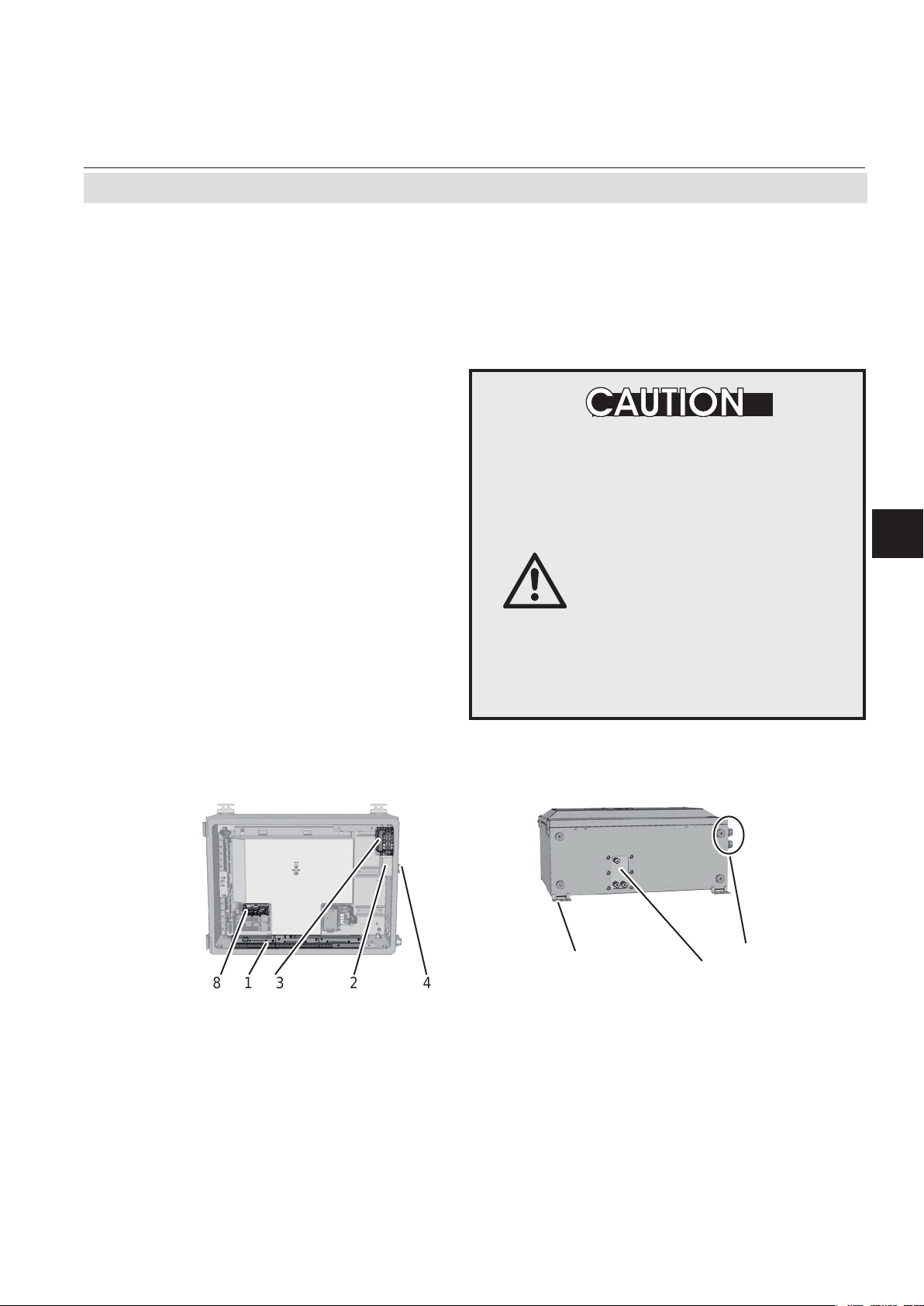
Short Form Manual
HASX2E-SFM-HS
02/2012
X-STREAM X2
2.6 Installation - X-STREAM X2XF Field Housings
Power and signal cables are connected using
internal screw-type terminals. This requires
opening the unit, which in turn requires releasing the fasteners on the housing.
Gas connectors are accessible from the outside, on the underside of the instrument.
The number and congration of the gas inlets
and outlets depends on the analytical application, and is noted on a sticker on the underside of the instrument next to the connectors.
Note on XXF!
Differing from single compartment XLF,
• the electrical connections are established in
the upper compartment,
• the gas connection ttings are at the lower
compartment.
To simplify installation, we recommend labelling the gas lines in accordance with these
markings. This avoids confusion should the
analyzer need to be disconnected for maintenance.
GASKETS AT LOW TEMPERATURES
Consider that enclosure gaskets may be frozen when
the instrument is installed
outdoors. Carefully open the
enclosure at temperatures
below -10 °C to not damage the
gaskets.
Damaged gaskets void the
ingress protection, possibly
causing property damage,
personal injury or death.
Installation
2
7
18 423
1 Terminals for signal cables
2 Mains lter
3 Power connections with integrated fuses
4 Glands for power cable
Fig. 2-11: X-STREAM X2XF Field housing - terminals, cable glands and gas connectors
Emerson Process Management GmbH & Co. OHG 2-17
5 Glands for signal cables
6 Gas inlets and outlets
7 Plugs for openings to connect housings
8 Ethernet connectors (optional)
Gas inlets
Gas outlets
5
6
Page 54

X-STREAM X2
2.6 Installation - X-STREAM X2XF Field Housings
Gas connections
Gas connections
max number 8
max for purging (incl. / separate) 2 incl.
material PVDF; stainless steel (opt.)
1
sizes 6/4 mm;
Signal in- and outputs
Preparation of signal cables
⁄4"
Short Form Manual
HASX2E-SFM-HS
02/2012
All signal cables are connected to screw-type
terminals located inside the housing. Access
to the internal components is gained by releasing the two fasteners at the top of the unit
and opening the front panel downwards.
All cables must be fed through cable glands
and secured with a gland nut.
Installing cable glands with shielded cables
1. Strip the cable
2. Expose braided
shield
3. Feed cable through
dome nut and clamping insert
Properly installed, the glands act as a strain
relief and guarantee EMC (electromagnetic
compatibility):
6. Push clamping insert
into body and tighten
dome nut
7.
Assemble into hou-
sing and you´re done!
4. Fold braided shield
over clamping insert
5. Make sure that braided shield overlaps
the O-ring by 2 mm
(3⁄32“)
Emerson Process Management GmbH & Co. OHG2-18
Page 55

Short Form Manual
HASX2E-SFM-HS
02/2012
Verify the power supply at installation site meets the specication given on
the analyzer´s nameplate label, before installing the instrument!
Verify power cables are disconnected and/or instrument is de-energized
prior to working at the terminals!
X-STREAM X2
2.6 Installation - X-STREAM X2XF Field Housings
ELECTRICAL SHOCK HAZARD
Verify the power cord is layed with a distance of at least 1 cm (0.4 in) to any
signal cable to ensure proper insulation from signal circuits!
The number of actually available signal out-
puts, and also the number of built-in modules
with screw-type terminals, varies according to
the congration of the unit.
A maximum of three modules with 36 termi-
nals each can be tted.
The terminals can be accessed by opening
the front panel of the instrument.
Characteristics of terminals:
2
Accepted wire gauge:
0.14…1.5 mm
end sleeves not required
(AWG 26…AWG 16),
Skinning length: 5 mm (0.2")
Thread: M2
Min. tightening torque: 0.25 Nm (2.21 in.lb)
Installation
2
Emerson Process Management GmbH & Co. OHG 2-19
Page 56

Short Form Manual
X-STREAM X2
HASX2E-SFM-HS
02/2012
2.6 Installation - X-STREAM X2XF Field Housings
Analog signals
Relay outputs 1-4
Terminals for analog signals and relay outputs 1 - 4 are located on the outer left module (termi-
nal block X1).
Specication of analog signal outputs: 4 (0) – 20 mA; burden: RB ≤ 500 Ω
Specication of relay outputs:
Electrical specication:
Dry relay change-over contacts can be used as
NO or NC.
max. 30 VDC, 1 A, 30 W
Notes!
• Consider
• the installation notes in section 2.7
• the notes on installing cable glands on page 2-18.
• Technical data and installation information for further available interfaces are given in the
X-STREAM X2 instruction manual. Connector layouts are part of the appendix of this manual.
P2.1 Channel 1, (+) 4 (0) - 20 mA
P2.2 Channel 1, GND
P2.3 Channel 2, (+) 4 (0) - 20 mA
P2.4 Channel 2, GND
P2.5 Channel 3, (+) 4 (0) - 20 mA
P2.6 Channel 3, GND
P2.7 Channel 4, (+) 4 (0) - 20 mA
P2.8 Channel 4, GND
P2.9 Channel 5, (+) 4 (0) - 20 mA
P2.10 Channel 5, GND
P2.11 not used
P2.12 not used
P3.1 not used
P3.2 not used
P3.3 Output 1 (Failure), NC
P3.4 Output 1 (Failure), NO
P3.5 Output 1 (Failure), COM
P3.6 Output 2 (Maintenance Request), NC
P3.7 Output 2 (Maintenance Request), NO
P3.8 Output 2 (Maintenance Request), COM
P3.9 Output 3 (Out of Spec), NC
P3.10 Output 3 (Out of Spec), NO
P3.11 Output 3 (Out of Spec), COM
P3.12 Output 4 (Function check), NC
P4.1 Output 4 (Function check), NO
P4.2 Output 4 (Function check), COM
P4.3 not used
P4.4
P4.5
P4.6
P4.7
P4.8
P4.9
P4.10
P4.11
P4.12
Serial Interface
*)
Relay Outputs
**)
Analog Outputs
Fig. 2-12: Terminal block X1 - Analog Outputs & Digital Outputs 1-4 (XSTA)
Emerson Process Management GmbH & Co. OHG2-20
Pin Signal
**)
Congration of relay output
terminals as per standard
factory setting (NAMUR status
signals)
Page 57

Short Form Manual
HASX2E-SFM-HS
02/2012
2.6 Installation - X-STREAM X2XF Field Housings
Connecting the power cord
The power cord is connected to screw-type
terminals located inside the housing.
Accepted wire gauge: 0.2…4 mm2 (AWG 24…AWG 12)
Recommended wire gauge
min. 1.5 mm² (AWG 15),
end sleeves not required
Skinning length: 8 mm (0.315")
Thread: M3
Min. tightening torque: 0.5 Nm (4.4 in.lb)
X-STREAM X2
Installation
2
ELECTRICAL SHOCK HAZARD
Verify the power supply at installation site meets the specication given on
the analyzer´s nameplate label, before installing the instrument!
Verify power cables are disconnected and/or instrument is de-energized
prior to working at the terminals!
Verify the power cord is layed with a distance of at least 1 cm (0.5“) to any
signal cable to ensure proper insulation from signal circuits!
Feed the power cable through the cable
gland at the instrument´s right side and strip
the outer insulation. Strip the individual wires
and connect to the terminals (a label is loca-
ted next to the terminals on the mains lter
housing).
Finally, tighten the outer dome nut to secure
the power cable.
Power supply
Live L
Neutral N
Earth PE
Fig. 2-13: Power supply connections
Emerson Process Management GmbH & Co. OHG 2-21
cable gland
Page 58

X-STREAM X2
2.6 Installation - X-STREAM X2XF Field Housings
ELECTRICAL SHOCK HAZARD
Before completing the electrical connection of the instrument, verify cables
are inserted and connected in correct manner!
Ensure the earthing conductor (protective earth; PE) is connected!
When all connections are correctly made and
checked,
• close the front panel and secure with the
two fasteners.
Short Form Manual
HASX2E-SFM-HS
02/2012
Emerson Process Management GmbH & Co. OHG2-22
Page 59

Short Form Manual
HASX2E-SFM-HS
02/2012
2.7 Installation - Notes on Wiring
2.7 Notes On Wiring Signal Inputs and Outputs
X-STREAM X2
Emerson Process Managament has made
every effort during the development process
to ensure that the X-STREAM analyzer series
ensures electromagnetic compatibility (EMC)
with respect to emission and interference resi-
stance, as conrmed by EMC measurements.
However, EMC is not wholly inuenced by the
design of the instrument, but to a large degree
by the on-site installation process. Please
observe the following sections and precauti-
ons to guarantee the safe and problem-free
operation of this analyzer.
2.7.1 Electrical shielding of cables
In order to minimise ambient electromagne-
We recommend using only shielded
tic interference, it is necessary to take care
making all electrical connections between the
analyzer and any other devices:
Fig. 2-14: Shielded signal cable, shielding connected at both ends.
signal cables. The shielding must be
connected at both ends to the housing
(Fig. 2-14).
Installation
2
On-site conditions often differ from test
• The shielding is connected only at one
environments and may require special precautions. Such a case arises when strong
electromagnetic elds which could induce
an interference current in the shielding. This
type of current creates a potential difference
between the connected housings.
Two possible methods of eliminating this are
described here. Fitters familiar with EMC
problems must decide which method should
be emplyed.
Fig. 2-15: Shielded signal cable, shielding connected at one end.
end (connecting to the analyzer is re-
commended): this gives better protection
against external interference, and inter-
ference currents are prevented because
the ground loop is interrupted.
Emerson Process Management GmbH & Co. OHG 2-23
Page 60

X-STREAM X2
Short Form Manual
HASX2E-SFM-HS
02/2012
2.7 Installation - Notes on Wiring
• Cables with double shielding are used: in
this case, one shielding is connected to
the analyzer housing, the other shielding
to the external device. This is advan-
This method is more expensive, but gi-
ves the best protection against external
interference and against interference
currents
.
tageous when both units are supplied
from different grids (e.g. when installed
in different buildings).
Fig. 2-16: Signal cable with double shielding, shieldings connected at alternate ends.
X-STREAM X2GP with XSTA or XSTD terminal adapters
In order to avoid measured values being inu-
enced by external interference signals when
terminal adapters are in use, the signal cable
shieldings must be connected to the analy-
zer housing by means of shield connector
terminals:
• uncover the signal cable shielding to a
length of 20 cm (8 in),
• pull up the contact part of the shield connector terminal,
• feed through the cable as illustrated in
Fig. 2-17: Shield connector terminal with cable
Fig 2-17,
• bring down the contact part onto the
shielding.
This results in a secure contact with the cable
shielding and improves the unit’s interference
resistance.
The individual wires are then connected as
described in seciton 2.6.
The shield connector must be properly or-
dered to t the cable diameter, and can be
retrotted:
Ø 1.5 - 6.5 mm: part # ETC02019
Ø 5 - 11 mm: part # ETC02020
Ø 10 - 17 mm: part # ETC02021
Ø 16 - 24 mm: part # ETC02022
Emerson Process Management GmbH & Co. OHG2-24
Page 61

Short Form Manual
HASX2E-SFM-HS
02/2012
X-STREAM X2
2.7 Installation - Notes on Wiring
2.7.2 Wiring inductive loads
Switching inductive loads creates electromagnetic interference:
When an inductive load (e.g. relay, valve) is
switched off, the magnetic eld resists the
change in current; this induces a high voltage across the coil contacts (several hundred
volts). This impulse propogates through the
connected cables and can influence any
electrical devices nearby or destroy signal
inputs and outputs. This can be avoided with
a simple precaution:
• A silicon diode is connected in parallel to
the load’s contacts. The induced impulse is thus short-circuited at its source.
The cathode must be connected to the
positive end of the coil, the anode to the
negative end (Fig 2-18).
Compatible lter components for standard
valves are available on request.
2.7.3 Driving high-current loads
Loads which draw a current in excess of the
specications for X-STREAM series analyzer
outputs (>30 mA / >1 A) may not be directly
driven from digital or relay outputs.
Such loads require external relays serving as
de-coupling modules: the X-STREAM output
drives the external relay , which in turn drives
the load.
In order to avoid interference, we recommend
supplying the analyzer and the high-current
loads from different sources (Fig 2-18).
As previously described, the use of suppressor diodes for inductive loads is highly
recommended.
Last
External relay
Installation
2
Analyzer output
Fig. 2-19: Driving high-current loads
Fig. 2-18: Suppressor diode for inductive loads.
Emerson Process Management GmbH & Co. OHG 2-25
Page 62

X-STREAM X2
2.7 Installation - Notes on Wiring
2.7.4 Driving multiple loads
Frequently, several loads in one system are
controlled by several analyzer outputs, whe-
reby the power for the loads derives from a
common source.
Special care is needed when wiring the loads
to minimize interference from switching these
loads:
• avoid connecting the loads in series:
Short Form Manual
HASX2E-SFM-HS
02/2012
Fig. 2-20: Loads in series
• It is recommended to wire the loads in
parallel, and to separately connect each
load to the power supply: Beginning at
the distribution point, lay both the + and
the - wires for each load together to the
load (Fig. 2-21). Interference is further
reduced if a twisted multi-core cable is
used.
Distribution point
Lay cables to the loads
together as far as possible
(using twisted-pair cables
if possible)
Fig. 2-21: Loads in parallel
Emerson Process Management GmbH & Co. OHG2-26
Page 63

Short Form Manual
HASX2E-SFM-HS
02/2012
X-STREAM X2
Chapter 3
Startup
Once the unit has been unpacked and installed, it is recommended to make some
adjustments (e.g. select the language) and
to perform some basic procedures (leak test
and calibrations).
In order for the information in this chapter
to be of any relevence, the unit must have
OPERATION AT LOW TEMPERATURES
When operating an instrument at temperatures below 0 °C (32 °F), do
NOT apply gas nor operate the internal pump before the warmup time has
elapsed!
Violation may result in condensation inside the gas paths or damaged
pump diaphragm!
Consider the related instructions in the X-STREAM X2 series manual!
been installed according to the instructions
in chapter 2.
For more detailled information on the topics
described in this chapter, read chapter 5 of
the X-STREAM X2 instruction manual.
Startup
3
The USB-Stick shipped with
your analyzer contains impor-
tant analyzer specic data in
the subfolder "Analyzer Documentation"!
To protect against data loss,
• print out and store in a safe
place all the les
or
• copy the subfolder to another data storage medium!
Emerson Process Management GmbH & Co. OHG 3-1
Page 64

X-STREAM X2
3.1 Performing a Leak Test
3.1 Performing a Leak Test
Before starting up the instrument, it appears
to be appropriate to perform a leak test, thus
ensuring the gas path system does not have
leaks, and to achieve best and proper measuring results.
The following procedure describes how to
perform a leak test with focus on the instrument.
The gas path system should be leak tested
at least on a bimonthly basis and after main-
tenance, replacement or repair of gas path
parts.
Note!
It is recommended to include external equip-
ment (e.g. cooler, dust lters, etc.) into a leak
test!
Short Form Manual
HASX2E-SFM-HS
HAZARD FROM GASES
Before opening gas paths
they must be purged with
ambient air or neutral
gas (N
) to avoid hazards
2
caused by toxic, ammable,
explosive or harmful to
health sample gas components!
Analyzer
02/2012
Required tools
• U-turn manometer for max. 1.45 psi
(100 mbar)
• Stop valve
Procedure
• Connect the water lled u-turn manome-
ter to the analyzer‘s sample gas output
(disconnect external gas lines).
• Install the stop valve between gas input
tting and a Nitrogen (N
) supply.
2
• Open the stop valve until the internal
gas path is under pressure of approx.
0.725 psi/50 mbar (corresponding to 19.7
inch/500 mm water column)
• Close the stop valve. After a short time
for the water to balance, the water level
must not change over a time period of
approx. 5 minutes!
overpressure
stop
valve
Water
Fig. 3-1: Leak Testing with U-turn Manometer
approx.
0.725 psi /
50 mbar
Max. pressure 7.25 psig
(500 mbar)!
Multi channel instruments:
Analyzers with parallel tubing
require separate leak tests for
each gas path !
Emerson Process Management GmbH & Co. OHG3-2
Page 65

Short Form Manual
HASX2E-SFM-HS
02/2012
3.2 The User Interface
X-STREAM X2
3.2 The User Interface
All X-STREAM gas analyzers have an alphanumeric display with four lines of 20
characters to display measuring and status
information and the easy-to-use menu-based
user interface for entering parameters. For
ease of understanding, the user can at any
time select one of three languages stored in
the unit (currently available: English, French,
German, Italian and Spanish in various com-
binations).
Units are operated using six keys on the front
panel.
Three LEDs on the front panel enable the
operating status to be recognised instantly.
Startup
3
Fig. 3-2: X-STREAM front panel
Emerson Process Management GmbH & Co. OHG 3-3
Page 66

X-STREAM X2
3.2.1 Display
3.2.2 Status LED
Short Form Manual
HASX2E-SFM-HS
02/2012
3.2 The User Interface
The display has 4x20 characters, either liquid
crystal or vacuum uorescent (LCD or VFD).
What information is displayed depends on
the currently displayed menu.
Three status LED indicate the unit’s status,
recognisable from a distance.
Status is indicated in accordance with the
German NAMUR NE 44 recommendations.
“Failure” is indicated when this red LED is lit.
A ashing red LED in the middle indicates
“Maintenance request”, “Function check” or
“Off-spec operation”.
The third, green LED indicates the power
supply status:
on: power supply OK
off: power supply interrupted
Emerson Process Management GmbH & Co. OHG3-4
Page 67

Short Form Manual
HASX2E-SFM-HS
02/2012
3.2.3 Keys
X-STREAM X2
3.2 The User Interface
Six keys enable the use of the menu system.
Depending on the operational mode (measu-
ring, browsing menus, editing) they have the
following functions:
ENTER key:
Mode Function
Measuring
Browsing
Editing Conrms new entry
MEASURE key:
Mode Function
Measuring (no function)
Browsing
Editing Cancels entry
UP / DOWN keys:
Mode Function
Measuring
Browsing
Editing Changes current parameter
Leaves the measurement display
Accesses submenu (..) or exe-
cutes command (!)
Returns to measurement display
Leaves the measurement display
Selects menu line
Goes to previous/next page,
when currently in a line beginning with /
Startup
3
Emerson Process Management GmbH & Co. OHG 3-5
Page 68

X-STREAM X2
3.2 The User Interface
LEFT key:
Mode Function
Measuring
Browsing
Editing
Short Form Manual
HASX2E-SFM-HS
02/2012
Leaves the measurement
display
Goes up 1 level or page in
menu system
Moves cursor 1 space
Leaves channel selection
Cancels editing of given pa-
rameter
Goes to previous page,
when
showing in rst line
RIGHT key:
Mode Function
Measuring Leaves the measurement
display
Browsing Accesses submenu (..)
Goes to next page, when
Editing
showing in fourth line
Moves cursor 1 space
Emerson Process Management GmbH & Co. OHG3-6
Page 69

Short Form Manual
HASX2E-SFM-HS
02/2012
3.3 Symbols Used
3.3 Symbols Used
In the following sections, the symbols and
typographical conventions described below
are used to describe the software menus and
navigation.
X-STREAM X2
Symbols and conventions used
lowing sections
Symbol Meaning
Within descriptions of procedures
Setup..
Setup..
Analog outputs..
Analog outputs..
Output1 (2...4)
Zero calibration..
Span calibration..
Adv. Calibration..
Apply gas..
Menu title
Parent (Setup) and current
Menu (Analog outputs)
As an example, the menu
for Output1 is displayed;
the menus for outputs 2 to
4 are identical
Display
Note!
Menus or lines on a grey
background are optional or
context-dependent, and are
not always displayed
Access levels:
in the fol-
Convention
Within descriptions
(Menu title)
6.2.2, page 6-12
CONTROL - ZOOM..
„Valves“ Parameter name
Never, 1 min Selectable values
0 ... 2000 Range of values
For a detailed description
of this Menü, see section
6.2.2 on page 6-12
Navigate from the main
menu via the CONTROL
menu to the ZOOM.. menu
Meaning
Startup
3
Access level 1
(user)
Access level 2
(expert)
Access level 3
(administrator)
Access level 4
(service level)
Emerson Process Management GmbH & Co. OHG 3-7
Page 70

X-STREAM X2
3.4 Software
Short Form Manual
HASX2E-SFM-HS
02/2012
3.4 Software
The analyzer software displays measurement results and status messages, allows
parameters to be set and edited and allows
maintenance functions (e.g. calibration) to be
carried out.
To make it possible to perform all these
functions on a 4x20 display, the software
is organised hierarchically: measurement
Function Description
Displaying
TEXT
Simple text (not selectable with
cursor)
A variable description ends
with a colon and the line can be
made up of up to 3 elements:
1. description
2. value: number or text
Editing
3. unit (optional)
VARIABLES
Examples:
Span gas: 2000 ppm
Tol.Check: Off
Variables without a colon can-
not be edited.
display is on the topmost level, while menus
and submenus are below (
X-STREAM
X2 series instruction manual).
The following methods are used to distinguish
between various functions, e.g. executing
commands:
Function Description
A command line text ends in a
colon; when this line is selec-
Executing
COMMANDS
ted and ENTER pressed, a
command is executed, e.g. a
calibration procedure.
Example:
Start calibration !
A menu line text ends in two
dots; when this line is selected
Selecting a
MENU
and ENTER pressed, a submenu is opened.
Example:
Setup..
3.4.1 Navigating and Editing
Selecting a line
Lines are selected using the (UP/DOWN)
keys.
The cursor is displayed over the rst character
of the selected line. It is moved down with the
DOWN key and up with the UP key.
If the cursor is in the rst line, pressing the
key will move it to the last line.
If the cursor is in the last line, pressing the
key will move it to the rst line.
An action in the selected line is initiated by
pressing the 8
key , i.e. opening a new menu,
starting a procedure or entering edit mode.
Emerson Process Management GmbH & Co. OHG3-8
Page 71

Short Form Manual
HASX2E-SFM-HS
02/2012
X-STREAM X2
3.4 Software
If a selected parameter has been changed,
the “function check” status is set, with the
following consequences:
• the middle LED lights
• the NAMUR relay is activated.
Browsing
Some menus have more than four entries,
and these cannot all be displayed at once. In
these menus, an indicator in the last () or
rst () line indicates the direction the menu
continues in.
Line 1
Line 2..
Line 3
Line 4
Line 1
Line 2..
Line 3
Line 4
The status can be reset by acknowledging it
in the “Acknowledgements” menu.
A “function check” message set off by editing
a parameter is automatically reset upon returning to the measurement display.
To show the following page, the cursor is
placed in the line with the indicator and the
UP or DOWN key pressed. Alternatively, the
LEFT or RIGHT key can be used, irrespective
of where the cursor is located.
Line 1
Line 2..
Line 3
Line 4
Startup
3
Menu continues downwards.
Menu continues upwards and
.
downwards..
Editing
Editing mode enables the setting of a para-
meter. It is initiated by pressing the 8
key.
The cursor is now placed over the last character of the current value. Pressing the keys
change the selected character; if it is a list of
possible values, the entire value is changed.
The and keys are used to select a spe-
cic character for editing.
Which characters are available depends on
the position of the cursor:
• It is not possible to select the minus sign or
decimal point as the last character
.
• It is not possible to select the decimal point
in integer values
.
Menu continues upwards.
• For decimal numbers, the decimal point
can be placed anywhere within certain
limits.
There are two ways to leave editing mode:
key: the value is veried (e.g. min/max).
8
If the value is possible, it is saved and
the new value displayed; if not, an
error message is displayed
.
key: Cancel: all settings and changes are
reset to their former values.
Emerson Process Management GmbH & Co. OHG 3-9
Page 72

X-STREAM X2
3.4 Software
Component selection menu
A single channel analyzer has only one
measurement channel (component): editing
any parameter will only effect this one channel.
A multi-channel analyzer requires that a
channel must be selected before its parame-
ters can be changed. When this selection is
necessary , a menu is automatically displayed;
it is not displayed on single-channel units.
3.4.2 Access Levels
Short Form Manual
HASX2E-SFM-HS
02/2012
Select component
Component: CO2.1
Back -
Access levels can be used to prevent changes
to parameters by unauthorised personnel.
The X-STREAM menu system supports four
prioritized access levels which can be acti-
vated and deactivated separately , and should
be supplied with their own access codes.
Level four has the highest priority and is
used for factory settings — only qualied
EMERSON service personnel have access
to this level.
Level three allows access to system admin
parameters, e.g. for data capture and processing systems.
Level two covers the expert settings, e.g.
basic settings for calibration.
Level one is the user level and includes
parameters which should be set by trained
personnel.
Any menus not assigned to one of these le-
vels are not editable or are of minor relevance.
In this chapter, the descriptions of the individual menus also indicate which level the
menus are in. These assignments cannot be
changed.
Access codes for levels 1 to 3 can be de-
ned, activated and deactivated by the client.
The analyzer is delivered with the following
settings:
Level Access code Status
1 00000001 Off
2 00000002 Off
3 00000003 Off
It is recommended to set new access codes
if they are to be activated.
Note!
If a lower level is locked (i.e. its code acti-
vated), all higher levels will also be locked.
If a higher level is unlocked (i.e. its code
deactivated), all lower levels will also be automatically unlocked.
Emerson Process Management GmbH & Co. OHG3-10
Page 73

Short Form Manual
HASX2E-SFM-HS
02/2012
Entering access codes
X-STREAM X2
3.4 Software
If an access code is required for a menu, the
following message is displayed:
Access Code 1
Code 00000001
Back - Press
3.4.3 Special Messages
Depending on the last action performed by the
user, one of the following messages may be
displayed to assist or inform the user (the two
conrmation messages are displayed only for
a few seconds):
Use
• the UP/DOWN keys to change the cur-
rently selected digit,
• the LEFT/RIGHT keys to select a different
digit,
• the ENTER key to submit the code
or
• the MEASURE key to leave edit mode
and return to the previous display.
Startup
3
(i)
-COMMAND EXECUTED-
Wrong Input
Min: 500
Max: 10.000
Press 8
Information on incorrect entry:
The value entered by the user is outside valid
limits. The display indicates what limits apply .
Pressing
screen to allow a valid setting to be entered.
Emerson Process Management GmbH & Co. OHG 3-11
8 returns the display to the previous
Conrmation of execution of command:
Conrms that a procedure (e.g. calibration)
has been started.
(i)
CANCELLED
Conrmation of cancellation:
Conrms that a procedure (e.g. calibration)
has been aborted.
Page 74

X-STREAM X2
3.5 Powering Up
3.5.1 Boot Sequence
Short Form Manual
HASX2E-SFM-HS
02/2012
3.5 Powering Up
When the unit is powered up, a series of internal tests is automatically performed. During
this time the front panel keys are disabled,
3.5.2 Measurement Display
The measurement display is shown
• automaticaly on completion of the boot
sequence
• when the MEASURE key is pressed
• automatically after a set period of time
of inactivity (i.e. with no keys being
pressed).
The information displayed in the four lines of
the measurement display can be determined
by the operator:
• Sample gas components, measuring
results and measuring units for each
channel
• additional measurements, e.g. pressu-
re, gas ow, temperature
• nothing (empty line)
The factory settings are as follows:
Line 1: measured value of channel 1
Line 2: measured value of channel 2
Line 3: measured value of channel 3
Line 4: measured value of channel 4
Note!
If less than four channels are installed in the
unit, only the values of the available channels
will be shown.
while the time remaining for the boot sequence counts down in the display.
Line 4 is also used to display plain text status
information (errors, maintenance requests,
function checks or off-spec performance).
If such messages are active, line 4 alternates
between the messages and the parameter
selected for line 4.
Active messages are stored in an internal
buffer. If there is more than one message in
the buffer, the display will cycle through them.
Each message is not just shown in the display
as text, but also indicated by the appropriate
LED on the front panel and the activation of
the appropriate NAMUR relay (if a relay has
been assigned to that NAMUR function;
X-STREAM X2 series instruction manual
).
Note!
There are also functions, that do activate a
relay or LED, but are not shown on the display
(e.g. concentration alarms). In such cases,
check the status menu for more information.
CO2.1 135.1 ppm
O2.2 201952 ppm
CO.3 58.8 ppm
H2.4 1.5 %
MEASUREMENT DISPLAY
Emerson Process Management GmbH & Co. OHG3-12
Page 75

Short Form Manual
HASX2E-SFM-HS
02/2012
3.6 Selecting the Language
X-STREAM X2
3.6 Selecting the Language
If the analyzer is operational and it becomes
clear that the incorrect language has been
set, which is unintelligible to the operator, the
following sequence of keypresses (starting at
the measurement display) can be used to set
the language.
If the system has been set up accordingly , the
code for access level 1 must be entered at this
point to enable access to the following menu.
Note!
The factory setting for this unit is “no code
required”. For ease of operation, it is recommended to use the factory settings for access
codes while setting up the unit for the rst
time. In the following sections, therefore, no
more reference will be made to any need for
entering a code.
Startup
3
Note!
The fourth press of the ENTER key in this
sequence access the “Language” parameter
line.
The DOWN key changes the language. Pressing ENTER will set this language and the
display is updated accordingly.
If the selected language is not the intended
one, the previous three steps can be repeated
until the intended language is set.
Emerson Process Management GmbH & Co. OHG 3-13
Page 76

X-STREAM X2
3.7 Calibrating the Analyzer
Short Form Manual
HASX2E-SFM-HS
02/2012
3.7 Calibrating the Analyzer
Note!
T o achieve best and proper measuring results
it is recommended to perform zero and span
calibrations on a regular weekly basis.
Also a zero calibration must always precede
a span calibration!
Zero calibration
Nitrogen (N2) or any other suitable neutral gas
is supplied to the gas path. The concentration
of the component of interest is declared to be
"zero" and so the measured signal during zero
calibrations is declared to be 0.
Span calibration
Span gases with concentrations of 80 % to
110 % of the upper measuring range limit is
supplied to the gas path (lower concentrati-
ons are acceptable, but inuence accuracy of
measurements if later sample gas concentrations are higher). The contained concentration
of the component of interest is setup as set
point, and the measured value during span
calibration is then declared to correspond to
that concentration.
Note!
If the current concentration is known, ambient
air may be used to span calibrate %-Oxygen
channels.
X-STREAM gas analyzers support several
calibration procedures:
Manual calibration
Typically a calibration procedure is carried out
manually by supplying the gases sequentially
by hand and activating the procedures via
front panel keys.The operator has to take
care to consider purge times and supply the
proper gases in correct order.
It is the operators responsibility to not perform
a span calibration without a preceding zero
calibration!
Advanced calibration
Advanced calibration is a more comfortable
variation of manual calibration, providing ONE
KEY calibrations supported by internal and/or
external valves. The analyzer automatically
supplies the right gas and considers purge
times.
Remote calibration
Remote calibrations may be activated by
means of digital inputs or Modbus commands.
Calibrations activated via digital inputs re-
quire either internal or external valves to be
installed. Modbus supports both calibrations
with or without valves as well as calibration
sequences.
Unattended automatic calibration
Unattended automatic calibrations are activa-
ted utilizing the analyzer software time interval
setting:
After a specied time interval has elapsed,
the analyzer automatically carries out valve
supported zero or span calibrations.
The main advantage is that no user interaction
is required to start a calibration or during cali-
brations: The analyzer automatically supplies
the right gas, considers purge times and, that
a span calibration has to be preceded by a
zero calibration.
The following sections describe
how to carry out manual calibrations.
For information about other
calibration procedures see the
X-STREAM X2 instruction manual.
Emerson Process Management GmbH & Co. OHG3-14
Page 77

Short Form Manual
HASX2E-SFM-HS
02/2012
3.7.1 Preparing Calibrations
X-STREAM X2
3.7 Calibrating the Analyzer
Consider the calibration notes
in section "Measurement spe-
cications"!
Before starting calibrations it is required to
tell the instrument the calibration gas concen-
trations.
Setup..
Calibration..
Calibration gases..
Calibration gases
ZeroGas: 0.0 ppm
SpanGas: 500.0 ppm
Starting from the measurement screen press
the DOWN key to open the MAIN MENU,
enter the SETUP-CALIBRATION.. menu and
directly enter the CALIBRATION GASES..
menu.
Multi-channel unit:
Select the channel to be calibrated in the
SELECT COMPONENT menu.
Enter the concentration value for the zero gas
to be used during zero calibration.
Enter the concentration value for the span
gas to be used during span calibration.
Note!
The units for the calibration gases are taken
from the related entry in the display setup
menu.
Startup
3
Multi-channel unit:
Press the key to enter the SELECT COM-
PONENT menu to change the settings for a
different channel.
When done, press the key to return to the
CALIBRATION menu.
Emerson Process Management GmbH & Co. OHG 3-15
Page 78

X-STREAM X2
3.7 Calibrating the Analyzer
Calibration gases...
Tol.Check: Off
Hold on cal: On
Purge time: 15 s
Example:
Measuring range: 0 ... 50 %
Zero gas: 0 %
Span gas: 50 %
Situation:
Due to a fault zero gas is supplied to carry
out a span calibration, instead of span gas.
Tolerance check disabled (Off):
The analyzer calibrates the span with the
wrong gas resulting in an analyzer out of tune.
Tolerance check enabled (10%; AutoOff):
Starting a span calibration with zero gas
connected instead of span gas, the analyzer
gives an error message and stops calibrating
because the measured (expected span gas)
value differs more than 10 % from the upper
measuring range limit.
Short Form Manual
HASX2E-SFM-HS
02/2012
By default the option "Tol.Check" (tolerance
check) is disabled (Off).
So tolerance check helps avoiding calibrating
with a wrong gas applied (e.g. starting a span
calibration while zero gas is owing) resulting
in an instrument out of tune (see example to
the left side).
With tolerance check enabled (10%) during
calibration the analyzer checks that the en-
tered (setpoint) values for zero gas and span
gas are reasonable compared to the currently
owing calibration gas. If this gas concen-
tration differs more than 10 % of measuring
range from zero gas (during zero calibration)
or span gas setup (during span calibration),
calibration is aborted and a maintenance
request alarm is set (LED and optional relay
output). Resetting the alarm requires to per-
form a valid calibration or to conrm it within
the CONTROL - ACKNOWLEDGEMENTS..
screen.
The 3rd option (AutoOff) has the same functionality as 10% except that the maintenance
request is reset after 2-3 minutes.
There are still situations when tolerance check
must be disabled, e.g. when calibrating after
changing the span gas concentration. In this
cases select Off.
Calibration gases...
Tol.Check: Off
Hold on cal: On
Purge time: 15 s
Note!
The last line ("purge time") shows up only
if the valve option is other than none (see
INSTALLED OPTIONS menu) and is used
for advanced, remote and unattended calibrations only..
Emerson Process Management GmbH & Co. OHG3-16
Page 79

Short Form Manual
HASX2E-SFM-HS
02/2012
3.7 Calibrating the Analyzer
3.7.2 Manual Calibration
Control..
Zero calibration..
Span calibration..
Adv.Calibration..
Apply gas..
3.7.2.1 Manual Zero Calibration
X-STREAM X2
Starting from the measurement screen press
the DOWN key to open the MAIN MENU and
enter the CONTROL.. menu.
To start a zero calibration select the rst line
Before selecting any further line
make sure the required calibra-
tion gas is applied and owing!
Supply all calibration gases
with the same ow as the samp-
le gas (recommeded approx. 1 l/
min), pressureless and utilizing
the right gas tting.
:
Startup
3
CANCEL calibration!
START calibration!
ZeroGas 0.000 ppm
CO2.1 0.200 ppm
Ensure the warm-up time after
switching on has elapsed!
Warm-up time is 15 to 50 minutes
depending on installed measu-
ring system and conguration!
Multi-channel unit:
Select the channel to be calibrated in the
SELECT COMPONENT menu.
The rst line gives you the choice to cancel
the procedure now.
Select the second line to start the calibra-
tion.
Line 3 shows the calibration gas setup
(here: required zero gas concentration is
Emerson Process Management GmbH & Co. OHG 3-17
Page 80

X-STREAM X2
Gasow ZeroGas
CO2.1 0.500 ppm
Procedure Zeroing
Time 10 s
Short Form Manual
HASX2E-SFM-HS
02/2012
3.7 Calibrating the Analyzer
0.000 ppm), while line 4 shows the currently
measured gas concentration.
After having started the calibration, watch the
screen for information about the status:
The rst lines shows the gas (channel) to be
calibrated as well as the currently measured
concentration (after zero calibration this value
should be set to "0").
The line "Procedure" shows what's currently
happening (Zeroing = calibration ongoing;
Purging = waiting for measuring system to
be lled with currently owing gas; None =
calibration nished), while the last line shows
the remaining time till end of calibration
(countdown starting from 40 seconds).
When nished press the LEFT key two times
to return to either
the SELECT COMPONENT menu (multi
channel analyzer only), select another chan-
nel to perform the steps described above to
zero calibrate this channel, too,
or
the CONTROL.. menu, which allows you to
start a span calibration. The procedure and
screens look similiar to those of a zero cali-
bration:
Select SPAN CALIBRATION...
Emerson Process Management GmbH & Co. OHG3-18
Page 81

Short Form Manual
HASX2E-SFM-HS
02/2012
3.7 Calibrating the Analyzer
3.7.2.2 Manual Span Calibration
CANCEL calibration!
START calibration!
SpanGas 20.000 ppm
CO2.1 16.200 ppm
Gasow SpanGas
CO2.1 20.000 ppm
Procedure Spanning
Time 10 s
X-STREAM X2
Before selecting any further line
make sure the required calibra-
tion gas is applied and owing!
Multi-channel unit:
Select the channel to be calibrated in the
SELECT COMPONENT menu.
The rst line gives you the choice to immediately cancel the procedure.
Select the second line to start the calibra-
tion.
Line 3 shows the calibration gas setup (here:
required span gas concentration is 20 ppm),
while line 4 shows the currently measured gas
concentration.After having started the calibration watch the screen for status information:
The display shows the currently owing gas,
the gas (channel) to be calibrated as well as
the currently measured concentration (after
span calibration it should be set to the expected value) and a countdown for the current
procedure:
The line "Procedure" shows what's currently
happening (Spanning = calibration ongoing;
Purging = waiting for measuring system to
be lled with currently owing gas; None =
calibration nished), while the last line shows
the remaining time till end of calibration
(countdown starting from 40 seconds).
When nished, either press
the LEFT key two times to return to the
SELECT COMPONENT menu (multi channel
analyzer only), select another channel and
perform the steps described above to zero
calibrate this channel, too,
or
the HOME key to return to the measurement
screen to nish with manual calibration procedures.
Startup
3
Emerson Process Management GmbH & Co. OHG 3-19
Page 82

X-STREAM X2
Short Form Manual
HASX2E-SFM-HS
02/2012
Emerson Process Management GmbH & Co. OHG3-20
Page 83

Short Form Manual
HASX2E-SFM-HS
02/2012
Chapter 4
Dismounting and Disposal
4.1 Dismounting and Diposal of the Analyzer
HAZARDS FROM DISMOUNTING
Dismounting instruments installed in hazardous area requires special
documents to be issued and instructions to be followed! Do not dismount
such instruments without written permit!
Failure to follow may result in explosion!
Gas lines may contain unhealthy or toxic gases, depending on the
application, the instrument has been used for! T ake care to purge such gas
lines prior to disconnection, to remove all unhealthy or toxic components.
X-STREAM X2
Failure to follow may result in personal injury or death!
ELECTRICAL SHOCK HAZARD WHEN DISMOUNTING
Dismounting instruments installed in hazardous area requires special
documents to be issued and instructions to be followed! Do not dismount
such instruments without written permit!
Failure to follow may result in explosion!
Gas lines may contain unhealthy or toxic gases, depending on the
application, the instrument has been used for! T ake care to purge such gas
lines prior to disconnection, to remove all unhealthy or toxic components.
HEAVY INSTRUMENT
Disposal
4
Field housings, intended for outside and wall mounted use, weigh between
26 kg (57 lb) and 63 kg (139 lb), depending on version and options installed.
Two people and/or lifting equipment is required to lift and carry these units.
Emerson Process Management GmbH & Co. OHG 4-1
Page 84

X-STREAM X2
4 Dismounting & Disposal
When the instrument has reached the end of its useful life, do not throw it in a
trash can!
This instrument has been made of materials to be recycled by waste disposal
contractors specialised in this eld. Let the instrument and the packing material
duly disposed of in environmentally sound manner. Ensure the equipment is
free of dangerous and harmful substances (decontaminated).
Take care of all local regulations for waste treatment.
Advice concerning the disposal of chemicals
Short Form Manual
HASX2E-SFM-HS
02/2012
This instrument may contain electrochemical sensors, e. g. for measuring O
For these sensors
2.
applies:
• Don‘t dispose of together with household carbage.
• At the end of useful life, the instrument and the sensors must be disposed of in compliance
with the wast regulations, see instructions below.
When the instrument has reached the end of its useful life,
• purge all gas lines with inert gas
• ensure all gas lines are pressureless
• disconnect all gas lines
• switch off power and signal lines
• disconnect and remove all electrical connections
• for wall mounted instruments, support the instrument before loosening the xing screws.
• properly ll out the Declaration of Decontamination ( X-STREAM X2 Instruction Manual)
• hand over the dismounted instrument together with the Declaration of Decontamination to a
waste disposal contractor. This contractor then has to disassemble the instrument, recycle
and dispose of in compliance with all applicable waste treatment regulations.
Emerson Process Management GmbH & Co. OHG4-2
Page 85

Short Form Manual
HASX2E-SFM-HS
02/2012
Appendix
This chapter contains
Block diagram page A-2
Assignment of Terminals and Sockets page A-15
X-STREAM X2
Appendix
A
Emerson Process Management GmbH & Co. OHG A-1
Page 86

X-STREAM X2
1 2 3 4 5 6 7 8 9 10 11 12 13 14 15 16
1 2 3 4 5 6 7 8 9 10 11 12 13 14 15 16
A.1 Block diagram
A
Short Form Manual
HASX2E-SFM-HS
02/2012
A.1 Block Diagram
B
Option
C
D
Sheet 13
+
E
von
of
13
1
Blatt
Sheet
Auftrags-Nr.:+=
F
4.300-5158/4
Ident-Nr.:
Option Option
Standard
Applicable sheets
Housing
X-STREAM Version
A
agreement. All rights are reserved.
contents thereof, are only allowed with our
others and the use or communication of the
Copying of this document, and giving it to
Sheet 11
Sheet 11
Sheet 11
Sheet 11
Sheet 11
Sheet 11
+
Sheet 9
++ +
Sheet 3
Sheet 2
19”
½
X2GC
Sheet 9
Sheet 9
Sheet 3
Sheet 3
+ + +
+ + +
Sheet 2
Sheet 4
19”
½
or
X2GK with
X2GK with
C Power Supply
D
B
Sheet 9
+
Sheet 5
+ +
Sheet 4
Sheet 9
+
Sheet 8
+
Sheet 6
Sheet 9
+ +
Sheet 8
X-STREAM X2
Block diagram
Beschreibung, description Zeichnung-Nr.: Drawing-No.: Index
+
Schmidt
Walther
Sheet 7
02.10.
Bearb.
20.01.11 MBa
11.11.10 MBa
03.10.
Gepr.
12.08.09 MBa
Datum Name
07
20___
19”
single compartment
Field housing, single comp.
Flameproof field housing,
Non-incendive field housing,
XLF
X2FD
X2GP
C Power Supply
A
C
XLFN
dual compartment
Field housing, dual comp.
Non-incendive field housing,
XXF
XXFN
D
E
TN1273: Aktualisiert
TN1345, TN1346, TN1347: Aktualisiert
E MBa11.11.11
F xx.xx.12
TN846: Trace Moisture hinzu
TN934: Aktualisiert
C
D
Neue Gehäusevarianten hinzu
B
Micro Index Änderung, revision Datum Name
gestattet. Alle Rechte vorbehalten.
Inhaltes sind nur mit unserer Zustimmung
Unterlage, Verwertung und Mitteilung ihres
Weitergabe sowie Vervielfältigung dieser
Emerson Process Management GmbH & Co. OHGA-2
Page 87

Short Form Manual
1 2 3 4 5 6 7 8 9 10 11 12 13 14 15 16
1 2 3 4 5 6 7 8 9 10 11 12 13 14 15 16
HASX2E-SFM-HS
02/2012
X-STREAM X2
A.1 Block Diagram
A
B
C
D
E
von
of
13
2
Blatt
Sheet
Auftrags-Nr.:+=
F
4.300-5158/4
Ident-Nr.:
3/A5
3
Appendix
4.300-7273/4
Zeichnung/Drawing
24V DC Input
X2GC
A
A
agreement. All rights are reserved.
contents thereof, are only allowed with our
others and the use or communication of the
Copying of this document, and giving it to
X-STREAM X2
Block diagram
Beschreibung, description Zeichnung-Nr.: Drawing-No.: Index
XLR Stecker
EMV Filter,
XLR Plug in
EMI Filter, fuseholder 5x20 mm
Sicherungshalter 5x20 mm
T 3.15 A / 250V
24V
Power Input
DC 10-30 V wide range
max. 2.5 A
B
FE
GND
Zeichnungs-/Sachnummer / Drawing-/Partnumber
Steckverbindung / plug connection
2-adrige Leitung / cable with 2 lines
Leitungsfarbe / cable colour
2
bl
Symbolerklärung:
Description of used icons:
C
D
E
4.xxx-xxxx
/2.4 Verweis auf Seite 2, Spalte 4 / reference to sh 2, row 4
TN1273: Aktualisiert
TN1345, TN1346, TN1347: Aktualisiert
E MBa11.11.11
F xx.xx.12
Walther
02.10.
Bearb.
11.11.10 MBa
20.01.11 MBa
TN846: Trace Moisture hinzu
TN934: Aktualisiert
C
D
Schmidt
03.10.
Datum Name
07
Gepr.
20___
12.08.09 MBa
Neue Gehäusevarianten hinzu
B
Micro Index Änderung, revision Datum Name
gestattet. Alle Rechte vorbehalten.
Inhaltes sind nur mit unserer Zustimmung
Unterlage, Verwertung und Mitteilung ihres
Weitergabe sowie Vervielfältigung dieser
Emerson Process Management GmbH & Co. OHG A-3
Page 88

X-STREAM X2
1 2 3 4 5 6 7 8 9 10 11 12 13 14 15 16
1 2 3 4 5 6 7 8 9 10 11 12 13 14 15 16
Short Form Manual
HASX2E-SFM-HS
02/2012
A.1 Block Diagram
A
5
P9
P8
Keyboard
Tastatur
UFPSW 01
chematics:
Stromlaufplan /
4.300-4970
s
XFP 01
Auf Frontplatte
At front panel
13
4.300-9133
3
XSP 01/P32
Direkt gekoppelt
64
XSP 01/P3
XSP 01
see sheet 9, 10
siehe Blatt 9, 10
4/B13
3
2/C11
+Power
4.300-7273
B
VFD
LCD
Option
P1
chematics:
Stromlaufplan /
4.350-0500
s
P4
P3
10
3
Directly coupled
P2
Signals
+Power
P3
4.300-9124
10
10
P33
Option
4.350-0380
4.350-0380
chematics:
chematics:
s
s
P1P2P31
P1P2P31
XSIA 01
XSIA 01
4.350-0380
chematics:
s
P1P2P25
XSIA 01
4.350-0380
chematics:
s
P1P2P13
XSIA 01
C
Option*1
P2
chematics:
s
XDIO 01
Stromlaufplan /
4.300-8057-V2
11/E11
P8P9P10
Serielle Kommunikation
4 x “NAMUR”-Relais
P2
2
Service Port
Service Schnittstelle
26
P1
P22
P32
P32
P26
XPSA 01 / 02
Stromlaufplan / schematics:
4.300-4660 / 4.350-0920
Siehe auch Blatt 9
P16
(QSPI)
11/B...
Serial Communication
4 x “NAMUR-Relays
Directly coupled
Direkt gekoppelt
Stromlaufplan /
Stromlaufplan /
Analog Output 4
Analog Output 4
Analogausgang 4
Analogausgang 4
Stromlaufplan /
Analog Output 3
Analogausgang 3
Stromlaufplan /
Analog Output 2
Analogausgang 2
Sub-D P4
4.300-4680
Sub-D P17
Sub-D P18
see also sheet 9
.1.1
Sub-D P27
.1.1
X1 X2 X4.1
.1.1
D
.25 .25
Directly coupled
Direkt gekoppelt
.9 .9
Flat ribbon cable
Flachbandkabel
.25 .25
Directly coupled
Direkt gekoppelt
E
von
of
13
3
Blatt
Sheet
*2
P1
XSTD 01
external screwterminaladapter
chematics:
4.350-0480
s
Stromlaufplan /
Externe Schraubklemmenadapter
Auftrags-Nr.:+=
F
Option
4.300-5158/4
(XDIO 01 + XSTD 01)
(XDIO 01 + XSTD 01)
Note 1: At maximum one additional option selectable
Hinweis 1: Es ist maximal eine zusätzliche Option möglich
Ident-Nr.:
*2
X2GC, X2GK
*Hinweis 2: Nicht im X2GK
*Note 2: Not in X2GK
Option
chematics:
4.350-0460
s
XSTA 01
Stromlaufplan /
P1 P7
external screwterminaladapter
Externer Schraubklemmenadapter
X-STREAM X2
Block diagram
Beschreibung, description Zeichnung-Nr.: Drawing-No.: Index
Schmidt
Walther
02.10.
03.10.
Datum Name
07
Gepr.
20___
Bearb.
12.08.09 MBa
11.11.10 MBa
20.01.11 MBa
A
agreement. All rights are reserved.
contents thereof, are only allowed with our
others and the use or communication of the
Copying of this document, and giving it to
Analog Output 1
Analogausgang 1
B
Intern
Internal
Extern
External
C
D
E
TN1273: Aktualisiert
TN1345, TN1346, TN1347: Aktualisiert
E MBa11.11.11
F xx.xx.12
TN934: Aktualisiert
D
Neue Gehäusevarianten hinzu
TN846: Trace Moisture hinzu
B
C
Micro Index Änderung, revision Datum Name
gestattet. Alle Rechte vorbehalten.
Inhaltes sind nur mit unserer Zustimmung
Unterlage, Verwertung und Mitteilung ihres
Weitergabe sowie Vervielfältigung dieser
Emerson Process Management GmbH & Co. OHGA-4
Page 89

Short Form Manual
1 2 3 4 5 6 7 8 9 10 11 12 13 14 15 16
1 2 3 4 5 6 7 8 9 10 11 12 13 14 15 16
HASX2E-SFM-HS
02/2012
X-STREAM X2
A.1 Block Diagram
A
*Hinweis 3: Nicht im XEGK
*Note 3: Not in X2GK
*Hinweis 4: Nicht für thermostatisierte
Analysatoren
*Note 4: Not for heated analysers
5/A5
2
*Hinweis 2: Es sind bis zu zwei Netzteile
im Analysator möglich
*Note 2: There are up to two power supplies possible in
the analyser
24V -
Netzteil
Power Supply
AC 100V-240V ~
100V-240V ~
Optionales zweites Netzteil
Optional second Power Supply
wide range *2 *3 *4
2
4.300-9125
24V DC
Netzteil
Netzteil
Netzteil
Netzteil
100V-240V ~
100V-240V ~
100V-240V ~
100V-240V ~
4.300-9125
wide range
wide range
wide range
wide range
Power Supply
Power Supply
Power Supply
Power Supply
AC 100V-240V ~
AC 100V-240V ~
AC 100V-240V ~
AC 100V-240V ~
4.300-8126
B
Hinweis: Bei einem Netzteil
Note: For one power supply
3/A5
5/A5
5/A6
2
2
4.300-9125
4.300-9125
24V -
24V -
24V -
24V -
24V DC
24V DC
24V DC
24V DC
4.300-8108
4.300-8113
2
C
*1
Heater 1
ETC02286
4.300-6452
Heizung 1
Temperaturesensor
Temperatursensor
2
2
2
4.300-8104
Connection if no XHM 01 is used
Übertemperaturschalter
2
2
P8
P1
P4
XHM 01
Stromlaufplan/schematic
P9
P6
2
Verbindung wenn keine XHM 01 eingebaut ist
4.300-8109
D
E
von
of
13
4
Blatt
Sheet
Auftrags-Nr.:+=
F
o
ptional Heater
Optionale Heizung
4.300-5158/4
Heater 2
ETC02286
ETC02286
Heizung 2
Overtemperaturswitch
Gn/ge
gn/ye
Erdungsbolzen auf der Heizungsabdeckung
2
P2
P7
4.350-0680/3
4.300-8101
Grounding pin on heater cover
*Hinweis 1: Nicht im X2GK
*Note 1: Not in X2GK
4.300-8101
Ident-Nr.:
Appendix
X2GP
gn/ye
Gn/ge
4.300-8100
Erdungsbolzen auf der Montageplatte
Grounding pin on mounting panel
X-STREAM X2
Block diagram
Beschreibung, description Zeichnung-Nr.: Drawing-No.: Index
Schmidt
Walther
A
02.10.
03.10.
Datum Name
20.01.11 MBa
Bearb.
11.11.10 MBa
07
Gepr.
20___
12.08.09 MBa
FKID2-50-4/1
Power entry module
2 fuseholder 5x20 mm
2-stage inlet Filter, 2-pole line switch,
Gerätestecker-Kombielement
2-Stufen Inlet Filter, Netzschalter
-polig, 2 Sicherungshalter 5x20 mm
2
T 4A/250V
T 4A/250V
L
N
PE
Power Input
AC 100 - 240 V Widerange
50 / 60 Hz
Gerätesteckdose
C14 gemäss IEC/EN 60320-1
Appliance-Inlet
C14 acc. To IEC/EN 60320-1
Zeichnungs-/Sachnummer / Drawing-/Partnumber
Neue Gehäusevarianten hinzu
TN846: Trace Moisture hinzu
TN934: Aktualisiert
TN1273: Aktualisiert
TN1345, TN1346, TN1347: Aktualisiert
B
C
D
E MBa11.11.11
F xx.xx.12
4.xxx-xxxx
/2.4 Verweis auf Seite 2, Spalte 4 / reference to sh 2, row 4
Micro Index Änderung, revision Datum Name
gestattet. Alle Rechte vorbehalten.
Inhaltes sind nur mit unserer Zustimmung
Unterlage, Verwertung und Mitteilung ihres
Weitergabe sowie Vervielfältigung dieser
A
agreement. All rights are reserved.
contents thereof, are only allowed with our
others and the use or communication of the
Copying of this document, and giving it to
Steckverbindung / plug connection
2-adrige Leitung / cable with 2 lines
Leitungsfarbe / cable colour
2
bl
Symbolerklärung:
Description of used icons:
B
C
D
E
Emerson Process Management GmbH & Co. OHG A-5
Page 90

X-STREAM X2
1 2 3 4 5 6 7 8 9 10 11 12 13 14 15 16
1 2 3 4 5 6 7 8 9 10 11 12 13 14 15 16
Short Form Manual
HASX2E-SFM-HS
02/2012
A.1 Block Diagram
A
5
P9
P8
Keyboard
Tastatur
UFPSW 01
chematics:
s
Stromlaufplan /
4.300-4970
XFP 01
Auf Frontplatte
At front panel
13
4.300-9133
3
XSP 01/P32
Direkt gekoppelt
64
XSP 01/P3
XSP 01
see sheet 9, 10
siehe Blatt 9, 10
2
4/B13
+Power
4.300-9125
B
VFD
LCD
Option
P1
chematics:
s
Stromlaufplan /
4.350-0500
P4
P3
10
3
Directly coupled
P2
Signals
+Power
P3
4.300-9124
10
10
P33
Option
4.350-0380
4.350-0380
chematics:
chematics:
s
s
P1P2P31
P1P2P31
XSIA 01
XSIA 01
4.350-0380
chematics:
s
P1P2P25
XSIA 01
4.350-0380
chematics:
s
P1P2P13
XSIA 01
C
Option*1
P2
chematics:
s
XDIO 01
Stromlaufplan /
P2
Option*1
P2
chematics:
s
XDIO 01
Stromlaufplan /
P8P9P10
4 x “NAMUR”-Relais
Analogausgang 4
Analogausgang 4
Analogausgang 3
Analogausgang 2
2
4.300-8057-V224.300-8057-V2
11/E11
Serielle Kommunikation
P32
P32
P26
P16
P2
P11
Service Port
Service Schnittstelle
26
P1
P22
XPSA 01 / 02
Stromlaufplan / schematics:
4.300-4660 / 4.350-0920
Siehe auch Blatt 9
(QSPI)
11/B...
Serial Communication
4 x “NAMUR-Relays
Directly coupled
Direkt gekoppelt
Stromlaufplan /
Stromlaufplan /
Analog Output 4
Analog Output 4
Stromlaufplan /
Analog Output 3
Stromlaufplan /
Analog Output 2
4.300-4680
4.300-4680
see also sheet 9
X4.2
Sub-D P4
.1.1
Sub-D P4
.1.1
Sub-D P27
.1.1
Sub-D P17
X1 X2 X4.1
.1.1
Sub-D P18
D
.25 .25
Directly coupled
Direkt gekoppelt
.25 .25
Directly coupled
Direkt gekoppelt
.9 .9
Flat ribbon cable
Flachbandkabel
.25 .25
Directly coupled
Direkt gekoppelt
E
von
of
13
5
Blatt
Sheet
Auftrags-Nr.:+=
P1
chematics:
4.350-0480
s
Stromlaufplan /
XSTD 01
Option
P1
XSTD 01
external screwterminaladapter
chematics:
4.350-0480
s
Stromlaufplan /
Externe Schraubklemmenadapter
(XDIO 01 + XSTD 01)
(XDIO 01 + XSTD 01)
Note 1: At maximum two additional options are selectable
Hinweis 1: Es sind maximal zwei zusätzliche Optionen möglich
F
4.300-5158/4
Ident-Nr.:
X2GP
Option
chematics:
4.350-0460
s
XSTA 01
Stromlaufplan /
P1 P7
external screwterminaladapter
Externer Schraubklemmenadapter
X-STREAM X2
Block diagram
Beschreibung, description Zeichnung-Nr.: Drawing-No.: Index
Schmidt
Walther
02.10.
03.10.
Datum Name
07
Gepr.
20___
Bearb.
12.08.09 MBa
11.11.10 MBa
20.01.11 MBa
A
agreement. All rights are reserved.
contents thereof, are only allowed with our
others and the use or communication of the
Copying of this document, and giving it to
Analog Output 1
Analogausgang 1
B
Intern
Internal
Extern
External
C
D
E
TN1273: Aktualisiert
TN1345, TN1346, TN1347: Aktualisiert
E MBa11.11.11
F xx.xx.12
TN846: Trace Moisture hinzu
TN934: Aktualisiert
C
D
Neue Gehäusevarianten hinzu
B
Micro Index Änderung, revision Datum Name
gestattet. Alle Rechte vorbehalten.
Inhaltes sind nur mit unserer Zustimmung
Unterlage, Verwertung und Mitteilung ihres
Weitergabe sowie Vervielfältigung dieser
Emerson Process Management GmbH & Co. OHGA-6
Page 91

Short Form Manual
1 2 3 4 5 6 7 8 9 10 11 12 13 14 15 16
1 2 3 4 5 6 7 8 9 10 11 12 13 14 15 16
HASX2E-SFM-HS
02/2012
X-STREAM X2
A.1 Block Diagram
A
8/A5
X10
4.300-9125
24V -
24V DC
2
Netzteil
Netzteil
100V-240V ~
100V-240V ~
Connection if Page 13 is active
Verbindung wenn Seite 13 aktiv ist
2
*Hinweis 1: Es sind bis zu zwei Netzteile
im Analysator möglich
*Note 1: There are up to two power supplies possible in
the analyser
Netzteil
wide range *1
Power Supply
AC 100V-240V ~
100V-240V ~
Optionales zweites Netzteil
Optional second Power Supply
4.300-9125
24V -
24V -
wide range
wide range
Power Supply
Power Supply
AC 100V-240V ~
AC 100V-240V ~
4.300-8126
1
3/B8
B
Hinweis: Bei einem Netzteil
Note: For one power supply
5/A6
2
4.300-9125
24V DC
24V DC
2
C
4.300-6452
Temperaturesensor
Temperatursensor
2
4.300-8108
4.300-8099
2
2
4.300-8104
Connection if no XHM 01 is used
D
optional Heater
Optionale Heizung
Heater 1
ETC02286
Heizung 1
Heater 2
ETC02286
ETC02286
Heizung 2
Overtemperaturswitch
Übertemperaturschalter
2
P8
P4
P9
Verbindung wenn keine XHM 01 eingebaut ist
2
P22P7
P1
4.350-0680/3
XHM 01
Stromlaufplan/schematic
P6
E
von
of
13
6
Blatt
Sheet
Auftrags-Nr.:+=
F
4.300-5158/4
Ident-Nr.:
Gn/ge
gn/ye
Erdungsbolzen auf der Heizungsabdeckung
Grounding pin on heater cover
4.300-8101
4.300-8101
Appendix
A
3
4.300-8118
EMV Filter 6ET1
4.271-7340
Zeichnung/drawing
2 fuseholder 5x20 mm
-polige Sicherung 5x20 mm
2
Power entry module with screw terminals,
Netzeingangsmodul mit Schraubklemmen,
T 6.3 A / 250V
L
Power Input
AC 100 - 240 V wide range
50 / 60 Hz
Models XLF, XLFN
A
agreement. All rights are reserved.
contents thereof, are only allowed with our
others and the use or communication of the
Copying of this document, and giving it to
X-STREAM X2
Block diagram
3
Gn/ge
Gn/ge
gn/ye
potted
EMI Filter
1-stage Filter
EMI Filter 6ET1
1-stufiges Filter
T 6.3 A / 250V
N
4.300-8102
Netzeingangsmodul mit Schraubklemmen,
PE
EMV Filter
4.271-6580
Zeichnung/drawing
2 fuseholder 5x20 mm
-polige Sicherung 5x20 mm
2
Power entry module with screw terminals,
T 4 A / 250V
L
4.271/6581
2-stage Filter
vergossen
2-stufiges Filter
Stromlaufplan/schematic
T 4 A / 250V
N
PE
4.300-8102
Erdungsbolzen auf der Montageplatte
gn/ye
Grounding pin on mounting panel
Beschreibung, description Zeichnung-Nr.: Drawing-No.: Index
Single compartment field housings
Schmidt
Walther
02.10.
03.10.
Datum Name
07
Gepr.
20___
Bearb.
12.08.09 MBa
11.11.10 MBa
20.01.11 MBa
Zeichnungs-/Sachnummer / Drawing-/Partnumber
Neue Gehäusevarianten hinzu
TN846: Trace Moisture hinzu
TN934: Aktualisiert
TN1273: Aktualisiert
Model X2F, X2FN, X2FD
Power Input
AC 100 - 240 V wide range
50 / 60 Hz
Symbolerklärung:
Description of used icons:
B
C
D
Steckverbindung / plug connection
2-adrige Leitung / cable with 2 lines
Leitungsfarbe / cable colour
2
bl
E
TN1345, TN1346, TN1347: Aktualisiert
B
C
D
E MBa11.11.11
F xx.xx.12
4.xxx-xxxx
/2.4 Verweis auf Seite 2, Spalte 4 / reference to sh 2, row 4
Micro Index Änderung, revision Datum Name
gestattet. Alle Rechte vorbehalten.
Inhaltes sind nur mit unserer Zustimmung
Unterlage, Verwertung und Mitteilung ihres
Weitergabe sowie Vervielfältigung dieser
Emerson Process Management GmbH & Co. OHG A-7
Page 92

X-STREAM X2
1 2 3 4 5 6 7 8 9 10 11 12 13 14 15 16
1 2 3 4 5 6 7 8 9 10 11 12 13 14 15 16
Short Form Manual
HASX2E-SFM-HS
02/2012
A.1 Block Diagram
A
8/A5
X10
2
*Hinweis 1: Es sind bis zu zwei Netzteile
im Analysator möglich
*Note 1: There are up to two power supplies possible in
the analyser
Netzteil
wide range *1
Power Supply
AC 100V-240V ~
100V-240V ~
Optionales zweites Netzteil
Optional second Power Supply
2
4.300-9125
24V -
24V DC
Netzteil
Netzteil
Netzteil
100V-240V ~
100V-240V ~
100V-240V ~
4.300-9125
wide range
wide range
wide range
Power Supply
Power Supply
Power Supply
AC 100V-240V ~
AC 100V-240V ~
AC 100V-240V ~
4.300-8126
B
Hinweis: Bei einem Netzteil
Note: For one power supply
8/A6
5/A6
2
2
4.300-9125
4.300-9125
24V -
24V -
24V -
24V DC
24V DC
24V DC
2
C
4.300-6452
Temperaturesensor
Temperatursensor
2
4.300-8108
4.300-8113
2
2
4.300-8104
Connection if no XHM 01 is used
2 fuseholder 5x20 mm
-polige Sicherung 5x20 mm
2
Power entry module with screw terminals,
Netzeingangsmodul mit Schraubklemmen,
D
optional Heater
Optionale Heizung
Heater 1
ETC02286
Heizung 1
Heater 2
ETC02286
ETC02286
Heizung 2
Overtemperaturswitch
Übertemperaturschalter
6
2
2
2
P8
P4
P9
3
Verbindung wenn keine XHM 01 eingebaut ist
EMV Filter 6ET1
4.271-7340
Zeichnung/drawing
T 6.3 A / 250V
P2
P7
P1
4.350-0680/3
XHM 01
Stromlaufplan/schematic
P6
4.300-8118
1-stage Filter
EMI Filter 6ET1
1-stufiges Filter
T 6.3 A / 250V
E
von
of
13
7
Blatt
Sheet
Auftrags-Nr.:+=
F
4.300-5158/4
Ident-Nr.:
Gn/ge
gn/ye
Erdungsbolzen auf der Trägerplatte
Grounding pin on mounting plate
4.300-8101
4.300-8100
XDF, XDFN
X-STREAM X2
Block diagram
Beschreibung, description Zeichnung-Nr.: Drawing-No.: Index
Erdungsbolzen auf der Montageplatte
Gn/ge
gn/ye
4.300-8102
Grounding pin on mounting panel
Schmidt
Walther
02.10.
03.10.
Datum Name
07
Gepr.
20___
Bearb.
12.08.09 MBa
11.11.10 MBa
20.01.11 MBa
L
N
PE
Power Input
AC 100 - 240 V wide range
50 / 60 Hz
Zeichnungs-/Sachnummer / Drawing-/Partnumber
Neue Gehäusevarianten hinzu
TN846: Trace Moisture hinzu
TN934: Aktualisiert
TN1273: Aktualisiert
TN1345, TN1346, TN1347: Aktualisiert
B
C
D
E MBa11.11.11
F xx.xx.12
4.xxx-xxxx
/2.4 Verweis auf Seite 2, Spalte 4 / reference to sh 2, row 4
Micro Index Änderung, revision Datum Name
gestattet. Alle Rechte vorbehalten.
Inhaltes sind nur mit unserer Zustimmung
Unterlage, Verwertung und Mitteilung ihres
Weitergabe sowie Vervielfältigung dieser
A
agreement. All rights are reserved.
contents thereof, are only allowed with our
others and the use or communication of the
Copying of this document, and giving it to
Steckverbindung / plug connection
2-adrige Leitung / cable with 2 lines
Leitungsfarbe / cable colour
2
bl
Symbolerklärung:
Description of used icons:
B
C
D
E
Emerson Process Management GmbH & Co. OHGA-8
Page 93

Short Form Manual
1 2 3 4 5 6 7 8 9 10 11 12 13 14 15 16
1 2 3 4 5 6 7 8 9 10 11 12 13 14 15 16
HASX2E-SFM-HS
02/2012
X-STREAM X2
A.1 Block Diagram
A
5
P9
P8
Keyboard
Tastatur
UFPSW 01
chematics:
Stromlaufplan /
4.300-4970
s
XIN 01/P8
XFP 01
Auf Frontplatte
At front panel
13
4.300-9133
3
XSP 01/P32
Direkt gekoppelt
64
XIN 01/X1
XSP 01/P3
XSP 01
see sheet 9, 10
siehe Blatt 9, 10
6/B13, 7/B13
2
4.300-9125
+Power
B
VFD
LCD
Option
P1
chematics:
Stromlaufplan /
4.350-0500
s
P4
P3
10
3
Directly coupled
P2
Signals
+Power
P3
4.300-9124
10
10
P33
P19
Option
4.350-0380
4.350-0380
chematics:
chematics:
s
s
P1P2P31
P1P2P31
XSIA 01
XSIA 01
4.350-0380
chematics:
s
P1P2P25
XSIA 01
4.350-0380
chematics:
s
P1P2P13
XSIA 01
C
Option*1
P2
chematics:
s
XDIO 01
Stromlaufplan /
P2
Option*1
Y-Cable
4.300-9127
Y-Kabel
P2
chematics:
s
XDIO 01
(QSPI)
2
4.300-8057-V224.300-8057-V2
11/E11
10/B4
11/B...
P8P9P10
Serial Communication
Serielle Kommunikation
4 x “NAMUR-Relays
4 x “NAMUR”-Relais
Directly coupled
Direkt gekoppelt
Stromlaufplan /
Stromlaufplan /
P32
P32
Analog Output 4
Analog Output 4
Analogausgang 4
Analogausgang 4
Stromlaufplan /
P26
Analog Output 3
Analogausgang 3
Stromlaufplan /
P16
Analog Output 2
Analogausgang 2
Stromlaufplan /
P11
Service Port
Service Schnittstelle
26
P1
P22
XPSA 01 / 02
Stromlaufplan / schematics:
4.300-4660 / 4.350-0920
Siehe auch Blatt 9
4.300-4680
4.300-4680
see also sheet 9
X4.2
Sub-D P4
.1.1
Sub-D P4
.1.1
Sub-D P27
.1.1
Sub-D P17
X1 X2 X4.1
.1.1
Sub-D P18
D
.25 .25
Flat ribbon cable
Flachbandkabel
.25 .25
4.300-9130
Flat ribbon cable
Flachbandkabel
9
4.300-9128
.9 .9
Flat ribbon cable
Flachbandkabel
.25 .25
4.300-9129
Flat ribbon cable
Flachbandkabel
E
von
of
13
8
Blatt
Sheet
Auftrags-Nr.:+=
P1
XSTD 01
P1
XSTD 01
*)
chematics:
4.350-0480
s
Stromlaufplan /
Stromlaufplan /
Option
internal screw terminal adapters
13/B11,D12
Interne Schraubklemmenadapter
2
chematics:
s
4.300-8130
4.350-0480
(XDIO 01 + XSTD 01)
(XDIO 01 + XSTD 01)
Note 1: At maximum two additional options are selectable
Hinweis 1: Es sind maximal zwei zusätzliche Optionen möglich
F
4.300-5158/4
Ident-Nr.:
Appendix
Fieldhousings (all)
chematics:
4.350-0460
s
XSTA 01
Stromlaufplan /
P1 P7
internal screw terminal adapter
Interner Schraubklemmenadapter
X-STREAM X2
Block diagram
Beschreibung, description Zeichnung-Nr.: Drawing-No.: Index
Schmidt
Walther
02.10.
03.10.
Datum Name
07
Gepr.
20___
Bearb.
12.08.09 MBa
11.11.10 MBa
20.01.11 MBa
A
A
agreement. All rights are reserved.
contents thereof, are only allowed with our
others and the use or communication of the
Copying of this document, and giving it to
Analog Output 1
Analogausgang 1
B
Intern
Internal
C
D
Intern
Internal
E
TN1273: Aktualisiert
TN1345, TN1346, TN1347: Aktualisiert
E MBa11.11.11
F xx.xx.12
TN846: Trace Moisture hinzu
TN934: Aktualisiert
C
D
Neue Gehäusevarianten hinzu
B
Micro Index Änderung, revision Datum Name
gestattet. Alle Rechte vorbehalten.
Inhaltes sind nur mit unserer Zustimmung
Unterlage, Verwertung und Mitteilung ihres
Weitergabe sowie Vervielfältigung dieser
Emerson Process Management GmbH & Co. OHG A-9
Page 94

X-STREAM X2
1 2 3 4 5 6 7 8 9 10 11 12 13 14 15 16
1 2 3 4 5 6 7 8 9 10 11 12 13 14 15 16
Short Form Manual
HASX2E-SFM-HS
02/2012
A.1 Block Diagram
A
P28
P21
P29
XPSA 01 / 02
Stromlaufplan / schematics:
P24
4.300-4660 / 4.350-0920
siehe auch Blatt 3, 5, 8
see also sheet 3, 5, 8
P33
P10
P31P30
P18P17P16P11
P6P7P4P5
B
8
C
D
Mess
Mess
8
10
SV2
4.300-9164
JP2
Stromlaufplan /
schematics:
4.300-4520
SSI 01
Feuchte
Durch-
E
von
of
13
9
Blatt
Sheet
Auftrags-Nr.:+=
gas-
pumpe 2
8
block 2
Ventil-
Valve-
unit 2
gas-
pumpe 1
Pump 1 Pump 2
8
unit 1
Ventil-
block 1
Valve-
Moisture
Stromlaufplan /
schematics:
4.300-4400
HTS 01
fluss-
schalter
Flow-Switch
F
4.300-5158/4
Ident-Nr.:
Ch2
Druck
Pressure
Ch1
Ch4Ch3Ch2
Temperatur
Temperature
Ch1
Ch4Ch3Ch2
Durchfluss
Flow
Ch1
P20P19P28P26
XSP 01
Stromlaufplan / schematics:
4.350-0520
P15P14P13P12
M2M1Ch4Ch2
physical components (depending on measurement system)
ChopperDC-detectors
Ch4Ch3Ch2
X-STREAM X2
Block diagram
Beschreibung, description Zeichnung-Nr.: Drawing-No.: Index
Schmidt
Walther
02.10.
03.10.
Bearb.
Datum Name
07
Gepr.
20___
XSP 01, XPSA 01 and physical components
Serial
Strahler
Source
P32
see sheet 3, 5, 8
siehe Blatt 3, 5, 8
Signals
P27
+Power
P24P25P23P21
A
agreement. All rights are reserved.
contents thereof, are only allowed with our
others and the use or communication of the
Copying of this document, and giving it to
B
C
Ch1
12.08.09 MBa
11.11.10 MBa
20.01.11 MBa
Ch3
DC-Detektoren
Ch1
Ch4Ch3Ch2 Ch5
Neue Gehäusevarianten hinzu
TN846: Trace Moisture hinzu
TN934: Aktualisiert
TN1273: Aktualisiert
physikalische Baugruppen (messprinzipabhängig)
AC-Detektoren
AC-detectors
Ch1
D
E
TN1345, TN1346, TN1347: Aktualisiert
B
C
D
E MBa11.11.11
F xx.xx.12
Thermostate control (option, not for X2GC)
thermostatisiert (Option, nicht für X2GC)
Micro Index Änderung, revision Datum Name
gestattet. Alle Rechte vorbehalten.
Inhaltes sind nur mit unserer Zustimmung
Unterlage, Verwertung und Mitteilung ihres
Weitergabe sowie Vervielfältigung dieser
Emerson Process Management GmbH & Co. OHGA-10
Page 95

Short Form Manual
1 2 3 4 5 6 7 8 9 10 11 12 13 14 15 16
1 2 3 4 5 6 7 8 9 10 11 12 13 14 15 16
HASX2E-SFM-HS
02/2012
X-STREAM X2
A.1 Block Diagram
A
P28
P21
P29
XPSA 01 / 02
Stromlaufplan / schematics:
P24
4.300-4660 / 4.350-0920
siehe auch Blatt 3, 5, 8
see also sheet 3, 5, 8
P10
P31P30
P18P17P16P11
P6P7P4P5
P20P19P26
XSP 01
Stromlaufplan / schematics:
4.350-0520
P15P14P13P12
Serial
P32
see sheet 3, 5, 8
siehe Blatt 3, 5, 8
Signals
P27
+Power
P24P25P23P21
A
agreement. All rights are reserved.
contents thereof, are only allowed with our
others and the use or communication of the
Copying of this document, and giving it to
B
8
8
+Power
9
9
8/C10
2
4.300-9125
34
34
B
C
P24
XFTB 02.1
P23
8
XFTB 02.1
P22
XFTB 02.1
P19
.350-0900
Stromlaufplan / schematics:
4
XFTB 02
XFTB 02....
P1
XFTB 02.2
P7
XFTB 02.1
P7
XFTB 02.1
P21
XFTB 02.1
P20
8
XFTB 02.1
P5
XFTB 02.1
P11
*Hinweis 1
*Note 1
XFTB 02.2
P11
XFTB 02.1
P13
XFTB 02.2
P12
XFTB 02.2
P13
XFTB 02.1
P12
XFTB 02.1
P10
XFTB 02.2
P9
XFTB 02.2
P10
XFTB 02.1
P9
XFTB 02.1
P8
XFTB 02.2
P8
XFTB 02.1
P15
XFTB 02.2
P14
XFTB 02.1
P15
XFTB 02.2
P14
XFTB 02.1
2
P4
XFTB 02....
2
P3
XFTB 02....
2
P2
XFTB 02....
P18
XFTB 02.2
P18
XFTB 02.1
P17
XFTB 02.2
P16
XFTB 02.2
P17
XFTB 02.1
P16
XFTB 02.1
C
D
Mess
Mess
Durch-
Ch2
Ch1
Ch4Ch3Ch2
Ch1
Ch4Ch3Ch2
Ch1
M2M1Ch4Ch2
Ch4Ch3Ch2
11/B...
11/E11
11/B...
11/E11
11/B...
11/E11
Ch1
Ch1
Ch4Ch3Ch2 Ch5
Ch1
D
E
von
of
13
10
Blatt
Sheet
Auftrags-Nr.:+=
gas-
pumpe 2
8
block 2
Ventil-
Valve-
unit 2
gas-
pumpe 1
Pump 1 Pump 2
8
unit 1
Ventil-
block 1
Valve-
fluss-
schalter
Flow-Switch
Druck
Pressure
on the number and configuration of physical components.
The mapping of AC- or DC-Detectors from the connectors on the XFTB 02 may vary.
Temperatur
Temperature
*Note 1: Up to two pcb’s XFTB 02 may be installed depending
F
4.300-5158/4
Ident-Nr.:
Appendix
A
Durchfluss
Flow
physical components (depending on measurement system)
ChopperDC-detectors
Strahler
Source
augruppen werden 1 oder 2 Stk. XFTB 02 eingesetzt.
Steckplätzen der XFTB 02 variieren.
B
*Hinweis 1: Je nach Anzahl und Konfiguration der physikalischen
Hierdurch kann die Zuordnung der AC- oder DC-Detektoren zu den
DC-Detektoren
physikalische Baugruppen (messprinzipabhängig)
AC-Detektoren
AC-detectors
Thermostate control (option)
thermostatisiert (Option)
E
X-STREAM X2
Block diagram
Beschreibung, description Zeichnung-Nr.: Drawing-No.: Index
Schmidt
Walther
02.10.
03.10.
Datum Name
Gepr.
Bearb.
12.08.09 MBa
11.11.10 MBa
20.01.11 MBa
Neue Gehäusevarianten hinzu
TN846: Trace Moisture hinzu
TN934: Aktualisiert
TN1273: Aktualisiert
B
C
D
E MBa11.11.11
07
20___
Micro Index Änderung, revision Datum Name
gestattet. Alle Rechte vorbehalten.
Inhaltes sind nur mit unserer Zustimmung
Unterlage, Verwertung und Mitteilung ihres
Weitergabe sowie Vervielfältigung dieser
XSP 01, XPSA 01 and physical components in dual compartment fieldhousing
TN1345, TN1346, TN1347: Aktualisiert
F xx.xx.12
Emerson Process Management GmbH & Co. OHG A-11
Page 96

X-STREAM X2
1 2 3 4 5 6 7 8 9 10 11 12 13 14 15 16
1 2 3 4 5 6 7 8 9 10 11 12 13 14 15 16
Short Form Manual
HASX2E-SFM-HS
02/2012
A.1 Block Diagram
A
B
C
D
E
von
of
13
11
Blatt
Sheet
Auftrags-Nr.:+=
F
Peltier Kühler
Temperaturesensor
Overtemperaturswitch
see page 9 or 10
siehe Seite 9 oder 10
Connected as a DC detector
Angeschlossen als DC-Detektor
Zeichnungs-/Sachnummer / Drawing-/Partnumber
Steckverbindung / plug connection
2-adrige Leitung / cable with 2 lines
Leitungsfarbe / cable colour
2
bl
Symbolerklärung:
Description of used icons:
4.xxx-xxxx
/2.4 Verweis auf Seite 2, Spalte 4 / reference to sh 2, row 4
see page 9 or 10
siehe Seite 9 oder 10
Connected as a DC detector
Angeschlossen als DC-Detektor
see page 9 or 10
siehe Seite 9 oder 10
Connected as a DC detector
Angeschlossen als DC-Detektor
see page 9 or 10
siehe Seite 9 oder 10
Connected as a DC detector
Angeschlossen als DC-Detektor
4
P1
chematics:
OXS 01
4.300-0800
s
Stromlaufplan /
Electrochemical Sensor
Elektrochemischer Sensor
2
X1
10/D4
8/C10
5/C10
4.300-8057
3/C10
2
4
10/D4
8/C10
5/C10
3/C10
2
4.300-8057
4
10/D4
8/C10
5/C10
3/C10
2
4.300-8057
Sensoren
it 4 ... 20 mA
m
chleifenstromversorgung
chematics:
XHA 01
Stromlaufplan /
JP1
TCD 01
ST3
SPI 01
WAP 100
P2
S
Sensors with 4 ... 20 mA looppower
4.350-0980
s
chematics:
4.350-0000
s
Stromlaufplan /
Thermal conductivity sensor
chematics:
4.350-0200
s
Wärmeleitfähigkeitssensor
Stromlaufplan /
chematics:
4.300-2000
s
Stromlaufplan /
Thermal conductivity sensor
Wärmeleitfähigkeitssensor
Temperatursensor
Übertemperaturschalter
2
2
P4
P23,
P24
XTEC 02
Trace Oxygen
Stromlaufplan/schematic
Spurensauerstoffmessung
XOX 01
Stromlaufplan /
2
2
2
PO
Paramagnetic O sensor
Paramagn. O -Sensor
VVS 03
Temp.-Sensor
Sensor
Temp.-
Heater
Beheizer
chematics:
IR sensor
4.300-4300
s
IR Sensor
Stromlaufplan /
Peltier Cooler
Overtemperaturswitch
Übertemperaturschalter
2
2
J2
P25,
P26
P3
4.350-1280/3
P22
P1
chematics:
4.350-0440
s
432
10/D4
8/C10
5/C10
3/C10
see page 9 or 10
siehe Seite 9 oder 10
4.300-8057
Connected as a DC detector
Angeschlossen als DC-Detektor
4
see page 9 or 10
siehe Seite 9 oder 10
Connected as a DC detector
Angeschlossen als DC-Detektor
see page 9 or 10
siehe Seite 9 oder 10
Connected as temperature sensor
Angeschlossen als Temperatursensor
see page 3, 5 or 8
siehe Seite 3, 5 oder 8
option, connected to P9
Optional angeschlossen an P9
4.300-5158/4
Ident-Nr.:
Physical components
X-STREAM X2
Block diagram
Beschreibung, description Zeichnung-Nr.: Drawing-No.: Index
Schmidt
Walther
02.10.
03.10.
Datum Name
07
Gepr.
20___
20.01.11 MBa
Bearb.
11.11.10 MBa
12.08.09 MBa
see page 9 or 10
siehe Seite 9 oder 10
Connected as an AC detector
Angeschlossen als AC-Detektor
4
see page 9 or 10
siehe Seite 9 oder 10
Connected as a DC detector
Angeschlossen als DC-Detektor
A
agreement. All rights are reserved.
contents thereof, are only allowed with our
others and the use or communication of the
Copying of this document, and giving it to
4
4.300-9150
JP1 P15
chematics:
POT 01
4.350-0600
s
Stromlaufplan /
Electrochemical sensor
Elektrochemischer Sensor
B
Thermostate control (option, not for XEGC)
thermostatisiert (Option, nicht für XEGC)
C
chematics:
UV sensor
4.300-2280
UVSS III
s
UV Sensor
Stromlaufplan /
D
see page 9 or 10
siehe Seite 9 oder 10
Connected as an AC detector
Angeschlossen als AC-Detektor
4
Neue Gehäusevarianten hinzu
TN846: Trace Moisture hinzu
TN934: Aktualisiert
TN1273: Aktualisiert
TN1345, TN1346, TN1347: Aktualisiert
B
C
D
E MBa11.11.11
F xx.xx.12
E
Micro Index Änderung, revision Datum Name
gestattet. Alle Rechte vorbehalten.
Inhaltes sind nur mit unserer Zustimmung
Unterlage, Verwertung und Mitteilung ihres
Weitergabe sowie Vervielfältigung dieser
Emerson Process Management GmbH & Co. OHGA-12
Page 97

Short Form Manual
1 2 3 4 5 6 7 8 9 10 11 12 13 14 15 16
1 2 3 4 5 6 7 8 9 10 11 12 13 14 15 16
HASX2E-SFM-HS
02/2012
X-STREAM X2
A.1 Block Diagram
A
B
C
D
E
von
of
13
12
Blatt
Sheet
Auftrags-Nr.:+=
F
4.300-5158/4
Ident-Nr.:
Appendix
A
agreement. All rights are reserved.
contents thereof, are only allowed with our
others and the use or communication of the
Copying of this document, and giving it to
A
X-STREAM X2
Block diagram
Beschreibung, description Zeichnung-Nr.: Drawing-No.: Index
Schmidt
Walther
02.10.
03.10.
Datum Name
07
Gepr.
20___
Bearb.
12.08.09 MBa
11.11.10 MBa
20.01.11 MBa
Intentionally left blank
Neue Gehäusevarianten hinzu
TN846: Trace Moisture hinzu
TN934: Aktualisiert
TN1273: Aktualisiert
TN1345, TN1346, TN1347: Aktualisiert
B
C
D
E MBa11.11.11
F xx.xx.12
B
C
D
E
Micro Index Änderung, revision Datum Name
gestattet. Alle Rechte vorbehalten.
Inhaltes sind nur mit unserer Zustimmung
Unterlage, Verwertung und Mitteilung ihres
Weitergabe sowie Vervielfältigung dieser
Emerson Process Management GmbH & Co. OHG A-13
Page 98

X-STREAM X2
1 2 3 4 5 6 7 8 9 10 11 12 13 14 15 16
1 2 3 4 5 6 7 8 9 10 11 12 13 14 15 16
Short Form Manual
HASX2E-SFM-HS
02/2012
A.1 Block Diagram
A
B
C
D
E
von
of
13
13
Blatt
Sheet
Auftrags-Nr.:+=
F
4.300-5158/4
Zeichnungs-/Sachnummer / Drawing-/Partnumber
Steckverbindung / plug connection
2-adrige Leitung / cable with 2 lines
Leitungsfarbe / cable colour
2
bl
Symbolerklärung:
Description of used icons:
4.xxx-xxxx
/2.4 Verweis auf Seite 2, Spalte 4 / reference to sh 2, row 4
1
*Hinweis 2: Es sind nur insgesamt zwei Netzteile
im Analysator möglich
*Note 2: There are only two power supplies in
the analyser possible
4.300-8130
24V -
24V DC
2
Netzteil
wide range *2
Power Supply
AC 100V-240V ~
100V-240V ~
4.300-8126
6/B8
4.300-9171
Temperaturesensor
Temperatursensor
2
8/E14
4.300-8108
4.300-9169
2
655228
ETC02580
Heaterjacket
Heiztasche
Overtemperaturswitch
Übertemperaturschalter
1
2
X11
8/E14
P8
P4
4.300-812924.300-8130
P7
P2
4.350-0680/3
XHM 02
Stromlaufplan/schematic
P6
Nur für X2FD
Only for X2FD
Ident-Nr.:
„Vapor Recovery“
A
agreement. All rights are reserved.
contents thereof, are only allowed with our
others and the use or communication of the
Copying of this document, and giving it to
X-STREAM X2
Block diagram
Beschreibung, description Zeichnung-Nr.: Drawing-No.: Index
Schmidt
Walther
02.10.
03.10.
Datum Name
07
Gepr.
20___
Bearb.
12.08.09 MBa
11.11.10 MBa
20.01.11 MBa
Neue Gehäusevarianten hinzu
TN846: Trace Moisture hinzu
TN934: Aktualisiert
TN1273: Aktualisiert
TN1345, TN1346, TN1347: Aktualisiert
B
C
D
E MBa11.11.11
F xx.xx.12
B
C
D
E
Micro Index Änderung, revision Datum Name
gestattet. Alle Rechte vorbehalten.
Inhaltes sind nur mit unserer Zustimmung
Unterlage, Verwertung und Mitteilung ihres
Weitergabe sowie Vervielfältigung dieser
Emerson Process Management GmbH & Co. OHGA-14
Page 99

Short Form Manual
HASX2E-SFM-HS
02/2012
A
.2 Assignment Of Terminals And Sockets
.2.1 Tabletop & Rack Mount Analyzers
A
X-STREAM X2
A.2 Assignment of Terminals and Sockets
Signal Pin
Channel 1, (+) 4 (0) - 20 mA 1
Channel 2, (+) 4 (0) - 20 mA 2
Channel 3, (+) 4 (0) - 20 mA 3
Analog
outputs
Channel 4, (+) 4 (0) - 20 mA 4
unused 5
unused 6
unused 7
Output1 (Failure) NC 8
Output1 (Failure) NO 9
Output1 (Failure) COM 10
Output3 (Off spec) NC 11
Output3 (Off spec) NO 12
Relay contacts
(Status signals)
Output3 (Off spec) COM 13
Pin Signal
14 Channel 1, GND
15 Channel 2, GND
16 Channel 3, GND
17 Channel 4, GND
18 unused
19 unused
20 Output2 (Maintenance request) NC
21 Output2 (Maintenance request) NO
22 Output2 (Maintenance request) COM
23 Output4 (Function check) NC
24 Output4 (Function check) NO
25 Output4 (Function check) COM
Note!
Conguration of relay contacts
as per standard factory setting (NAMUR
status signals)
Socket X1 - Analog outputs, relay outputs 1...4
(Assignment of screw terminals adaptor: see XSTA on next page)
Signal Pin
Input 1 1
Input 2 2
Input 3 3
inputs
Digital
Input 4 4
GND for all digital inputs 5
unused 6
unused 7
Output 5 NC 8
Output 5 NO 9
Output 5 COM 10
Output 6, NC 11
Output 6, NO 12
Output 6, COM 13
Output 7, NC 14
Digital
outputs
Output 7, NO 15
Output 7, COM 16
Output 8, NC 17
Output 8, NO 18
Output 8, COM 19
Pin Signal
20 Input 5
21 Input 6
22 Input 7
23 Output 9, NC
24 Output 9, NO
25 Output 9, COM
26 Output 10, NC
27 Output 10, NO
28 Output 10, COM
29 Output 11, NC
30 Output 11, NO
31 Output 11, COM
32 Output 12, NC
33 Output 12, NO
34 Output 12, COM
35 Output 13, NC
36 Output 13, NO
37 Output 13, COM
Analog
outputs
Relay contacts
(Status signals)
inputs
Digital
Note!
Digital
outputs
The conguration illustrated
here is that of the rst socket,
labelled X4.1.
Inputs 8-14 and outputs 1422, are on the second socket
(X4.2), if installed.
Pin no.
Pin
6
7
8
9
MOD 485/
2 wire
MOD 485/
4 wire
Pin
1
2
3
4
5
RS 232
1 Common Common Common
2
3
4
not used not used
not used not used
not used
RXD1(+)
RXD
TXD
not used
5 D1(+) TXD1(+) Common
6
7
8
9 D0(-) TXD0(-)
not used not used not used
not used not used not used
not used
RXD0(-)
not used
not used
Connector X2 - IOIOI - Serial Modbus interface
(Assignment of screw terminals adaptor: see XSTA on next page)
1: ME
2: + 24 V
3: 0 V (⊥)
2 3 1
Pin 1
Pin 8
Pin
9
8
7
6
Pin no.
Pin
5
4
3
2
1
RS 232
1 Common
2 RXD
3 TXD
4
not used
5 Common
6
7
8
9
not used
not used
not used
not used
Service Port Socket -
Serial RS 232 interface
Pin no.
Signal
1 TX+
2 TX3 RX+
6 RX-
other
not used
Appendix
A
Socket X4 - Digital I/O
(Assignment of screw terminals adaptor: see XSTD on next page)
Emerson Process Management GmbH & Co. OHG A-15
DC 24 V Input (1⁄2 19 in analyzer)
Ethernet connector
for Modbus
Page 100

X-STREAM X2
.2.2 Field Housings
A
Short Form Manual
HASX2E-SFM-HS
02/2012
A.2 Assignment of Terminals and Socket
XSTA: Standard strip with standard and optional signals XSTD: First optional strip with
optional 7 Dig Inputs and 9 Dig Outputs
P4.12
Serial Interface
*)
See table below
*)
Relay Outputs
**)
Conguration of relay output termi-
**)
nals as per standard factory setting
(NAMUR status signals)
Analog Outputs
P2.8 Output 12, NO
P2.9 Output 12, COM
P2.10 Output 13, NC
P2.11 Output 13, NO
P2.12 Output 13, COM
Pin
9
8
7
6
P2.4 Output 11, NC
P2.5 Output 11, NO
P2.6 Output 11, COM
P2.6 Output 12, NC
P4.11 Output 9, NO
P4.12 Output 9, COM
P2.1 Output 10, NC
P2.2 Output 10, NO
P2.3 Output 10, COM
Pin
5
4
3
2
1
P4.7 Output 8, NC
P4.8 Output 8, NO
P4.9 Output 8, COM
P4.10 Output 9, NC
P4.6 Output 7, COM
P4.2 Output 6, NO
P4.3 Output 6, COM
P4.4 Output 7, NC
P4.5 Output 7, NO
Pin Signal
P2.1 Channel 1, (+) 4 (0) - 20 mA
P2.2 Channel 1, GND
P2.3 Channel 2, (+) 4 (0) - 20 mA
P2.4 Channel 2, GND
P2.5 Channel 3, (+) 4 (0) - 20 mA
P2.6 Channel 3, GND
P2.7 Channel 4, (+) 4 (0) - 20 mA
P2.8 Channel 4, GND
P2.9 not used
P2.10 not used
P2.11 not used
P2.12 not used
P3.1 not used
P3.2 not used
P3.3 Output 1 (Failure), NC
P3.4 Output 1 (Failure), NO
P3.5 Output 1 (Failure), COM
P3.6 Output 2 (Maintenance Request), NC
P3.7 Output 2 (Maintenance Request), NO
P3.8 Output 2 (Maintenance Request), COM
P3.9 Output 3 (Out of Spec), NC
P3.10 Output 3 (Out of Spec), NO
P3.11 Output 3 (Out of Spec), COM
P3.12 Output 4 (Function check), NC
P4.1 Output 4 (Function check), NO
P4.2 Output 4 (Function check), COM
P4.3 not used
P4.4
P4.5
P4.6
P4.7
P4.8
P4.9
P4.10
P4.11
Assignment of serial interface terminals
Terminal
MOD 485/
2 wire
P4.4 SER1 Common Common Common
P4.5 SER2
P4.6 SER3
P4.7 SER4
not used not used
not used not used
not used
P4.8 SER5 D1(+) TXD1(+) Common
P4.9 SER6
P4.10 7
P4.11 8
not used not used not used
not used not used not used
not used
P4.12 9 D0(-) TXD0(-)
Signal Terminals Strips
MOD 485/
4 wire
RXD1(+)
RXD0(-)
RS 232
RXD
TXD
not used
not used
not used
Pin no.
RS 232
1 Common
2 RXD
3 TXD
4
not used
5 Common
6
7
8
9
not used
not used
not used
not used
Service Port Connector -
Serial RS 232 interface
P3.10 Output 5, NC
P3.11 Output 5, NO
P3.12 Output 5, COM
P4.1 Output 6, NC
P3.5 Input 5
P3.6 Input 6
P3.7 Input 7
P3.8 GND for Inputs 1-7
P3.9 not used
Digital InputsDigital Outputs
P3.4 Input 4
P2.12 Output 22, COM
Pin Signal
P3.1 Input 1
P3.2 Input 2
P3.3 Input 3
Note!
Line and neutral
terminals with
built-in fuse holders
L
N
PE
L= Line
N= Neutral
PE= Protective Earth
Power cord
entry
Power terminals
XSTD: Second optional strip with another set of
optional 7 Dig Inputs and 9 Dig Outputs
P3.11 Output 14, NO
P3.12 Output 14, COM
P4.1 Output 15, NC
P4.2 Output 15, NO
P4.3 Output 15, COM
P4.4 Output 16, NC
P4.5 Output 16, NO
P4.6 Output 16, COM
P4.7 Output 17, NC
P4.8 Output 17, NO
P4.9 Output 17, COM
P4.10 Output 18, NC
P4.11 Output 18, NO
P4.12 Output 18, COM
P2.1 Output 19, NC
P2.2 Output 19, NO
P2.3 Output 19, COM
P2.4 Output 20, NC
P2.5 Output 20, NO
P2.6 Output 20, COM
P2.6 Output 21, NC
P2.8 Output 21, NO
P2.9 Output 21, COM
P2.10 Output 22, NC
P2.11 Output 22, NO
Pin 1 Pin 8
Flameproof (cast) housingFieldhousing
P3.1 Input 8
P3.2 Input 9
P3.3 Input 10
P3.4 Input 11
P3.5 Input 12
P3.6 Input 13
P3.7 Input 14
P3.8 GND for Inputs 8-14
P3.9 not used
P3.10 Output 14, NC
Digital InputsDigital Outputs
Pin no.
Signal
1 TX+
2 TX3 RX+
6 RX-
other
not used
Ethernet connector
for Modbus
Pin Signal
Emerson Process Management GmbH & Co. OHGA-16
 Loading...