

Page 1

Model TCL
Total Chlorine Analyzer
Instruction Manual
PN 51-TCL54e/rev.B
May 2007
Page 2
WARNING
ELECTRICAL SHOCK HAZARD
Making cable connections to and servicing
this instrument require access to shock hazard level voltages which can cause death or
serious injury.
Be sure to disconnect all hazardous voltage
before opening the enclosure.
Relay contacts made to separate power
sources must be disconnected before servicing.
Electrical installation must be in accordance
with the National Electrical Code
(ANSI/NFPA-70) and/or any other applicable
national or local codes.
Unused cable conduit entries must be
securely sealed by non-flammable closures
to provide enclosure integrity in compliance
with personal safety and environmental protection requirements.
The unused conduit openings need to be
sealed with NEMA 4X or IP65 conduit plugs
to maintain the ingress protection rating
(IP65).
For safety and proper performance this
instrument must be connected to a properly
grounded three-wire power source.
Proper relay use and configuration is the
responsibility of the user.
No external connection to the instrument of
more than 69VDC or 43V peak allowed with
the exception of power and relay terminals.
Any violation will impair the safety protection
provided
Do not operate this instrument without front
cover secured. Refer installation, operation
and servicing to qualified personnel.
ESSENTIAL INSTRUCTIONS
READ THIS PAGE BEFORE
PROCEEDING!
Rosemount Analytical designs, manufactures, and tests its
products to meet many national and international standards. Because these instruments are sophisticated technical products, you must properly install, use, and maintain
them to ensure they continue to operate within their normal
specifications. The following instructions must be adhered
to and integrated into your safety program when installing,
using, and maintaining Rosemount Analytical products.
Failure to follow the proper instructions may cause any one
of the following situations to occur: Loss of life; personal
injury; property damage; damage to this instrument; and
warranty invalidation.
• Read all instructions prior to installing, operating, and
servicing the product. If this Instruction Manual is not the
correct manual, telephone 1-800-654-7768 and the
requested manual will be provided. Save this Instruction
Manual for future reference.
• If you do not understand any of the instructions, contact
your Rosemount representative for clarification.
• Follow all warnings, cautions, and instructions marked on
and supplied with the product.
• Inform and educate your personnel in the proper installation, operation, and maintenance of the product.
• Install your equipment as specified in the Installation
Instructions of the appropriate Instruction Manual and
per applicable local and national codes. Connect all
products to the proper electrical and pressure sources.
• To ensure proper performance, use qualified personnel to
install, operate, update, program, and maintain the product.
• When replacement parts are required, ensure that qualified people use replacement parts specified by
Rosemount. Unauthorized parts and procedures can
affect the product’s performance and place the safe operation of your process at risk. Look alike substitutions may
result in fire, electrical hazards, or improper operation.
• Ensure that all equipment doors are closed and protective covers are in place, except when maintenance is
being performed by qualified persons, to prevent electrical shock and personal injury.
WARNING
This product is not intended for use in the light industrial, residential or commercial environment, per the
instrument’s certification to EN50081-2.
Emerson Process Management
Rosemount Analytical Inc.
2400 Barranca Parkway
Irvine, CA 92606 USA
Tel: (949) 757-8500
Fax: (949) 474-7250
http://www.raihome.com
© Rosemount Analytical Inc. 2006
Page 3
Page 4

CAUTION
SENSOR/PROCESS
APPLICATION COMPATIBILITY
Wetted materials may not be compatible with process com position and
operating conditions. Application
compat ibility is entirely the responsibility of the user.
DANGER
HAZARDOUS AREA INSTALLATION
Installations near flammable liquids or in hazardous area locations must be carefully evaluated by qualified on site safety personnel.
This device is not
Intrinsically Safe or
Explosion Proof.
To secure and maintain an intrinsically safe
installation, the certified safety barrier,
transmitter, and sensor combi nation must
be used. The installation system must comply with the governing approval agency (FM,
CSA or BASEEFA/CENELEC) hazardous
area classification requirements. Consult
your analyzer/transmitter instruc tion manual
for details.
Proper installation, operation and servicing
of this device in a Hazardous Area Instal lation is entirely the responsibility of the user.
About This Document
This manual contains instructions for installation and operation of the Model TCL Total
Chlorine Analyzer.
The following list provides notes concerning all revisions of this document.
Rev. Level
Date Notes
A 7/05 This is the initial release of the product manual. The manual
has been reformatted to reflect the Emerson documentation
style and updated to reflect any changes in the product offering.
B 2/06 Corrected typographical errors. Added statement to calibration
section concerning initial stabilization time.
Page 5

MODEL TCL TABLE OF CONTENTS
MODEL TCL
TOTAL CHLORINE ANALYZER
TABLE OF CONTENTS
Section Title Page
1.0 DESCRIPTION AND SPECIFICATIONS................................................................. 1
1.1 Features and Applications ...................................................................................... 2
1.2 Specifications — Sample Conditioning System ...................................................... 3
1.3 Specifications — Model 54e-24 Analyzer ................................................................ 3
1.4 Specifications — Model 499ACL-02 Sensor............................................................ 4
1.5 Performance Specifications — Complete System ................................................. 4
1.6 Ordering Information and Accessories ................................................................... 5
2.0 PRINCIPLES OF OPERATION .............................................................................. 7
3.0 INSTALLATION ...................................................................................................... 8
3.1 Unpacking and Inspection ...................................................................................... 8
3.2 Installation................................................................................................................ 8
4.0 WIRING .................................................................................................................. 14
4.1 Prepare Analyzer Conduit Openings ....................................................................... 14
4.2 Provide Power to the Sample Conditioning System ................................................ 14
4.3 Make Power, Alarm, Output, and Sensor Connections in the Analyzer................... 14
4.4 Apply Power to the Analyzer and Complete Quick Start.......................................... 16
5.0 START-UP .............................................................................................................. 17
5.1 Start Sample Flow.................................................................................................... 17
5.2 Prepare the Reagent ............................................................................................... 17
5.3 Zero the Sensor....................................................................................................... 17
5.4 Begin Operation and Calibrate the Sensor.............................................................. 17
6.0 DISPLAY AND OPERATION .................................................................................. 18
6.1 Display..................................................................................................................... 18
6.2 Keypad..................................................................................................................... 18
6.3 Programming and Calibrating the Solu Comp II — Tutorial..................................... 19
6.4 Security.................................................................................................................... 20
6.5 Using Hold ............................................................................................................... 20
7.0 PROGRAMMING THE ANALYZER ....................................................................... 21
7.1 General.................................................................................................................... 21
7.2 Changing Start-up Setting........................................................................................ 21
7.3 Configuring and Ranging the Outputs ..................................................................... 22
7.4 Configuring Alarms and Assigning Setpoints ........................................................... 24
7.5 Selecting the Type of Measurement ........................................................................ 27
7.6 Choosing Temperature Units and Manual or Automatic Temperature Compensation 28
7.7 Setting a Security Code........................................................................................... 29
7.8 Noise Rejection........................................................................................................ 29
7.9 Resetting Factory Calibration and Factory Default Settings.................................... 30
7.10 Selecting a Default Screen, Language, and Screen Contrast ................................. 31
i
Page 6

ii
MODEL TCL TABLE OF CONTENTS
TABLE OF CONTENTS CONT'D.
8.0 CALIBRATION ........................................................................................................ 32
8.1 Introduction.............................................................................................................. 32
8.2 Calibrating Temperature .......................................................................................... 32
8.3 Calibration................................................................................................................ 34
9.0 MAINTENANCE ..................................................................................................... 39
9.1 54e Analyzer............................................................................................................ 39
9.2 Total Chlorine Sensor .............................................................................................. 41
9.3 Sample Conditioning System................................................................................... 43
10.0 TROUBLESHOOTING ........................................................................................... 48
10.1 Overview.................................................................................................................. 48
10.2 Troubleshooting Using Fault Codes ........................................................................ 48
10.3 Troubleshooting When No Error Message is Showing............................................ 49
10.4 Simulating Inputs ..................................................................................................... 52
11.0 RETURN OF MATERIAL ........................................................................................ 53
LIST OF TABLES
Number Title Page
7-1 Default Settings ...................................................................................................... 21
9-1 Replacement Parts for 54e Analyzer (Panel Mount Version) ................................. 39
9-1 Replacement Parts for 54e Analyzer (Wall Mount Version) ................................... 40
9-1 Spare Parts ............................................................................................................ 42
9-1 Replacement Parts and Reagent for Sample Conditioning System ...................... 47
Page 7

MODEL TCL TABLE OF CONTENTS
TABLE OF CONTENTS CONT'D.
LIST OF FIGURES
Number Title Page
1-1 Dimensions of TCL Case ........................................................................................ 6
2-1 Schematic of Sample Conditioning System and Analyzer .................................... 7
3-1 Panel Mount Installation ......................................................................................... 9
3-2 Pipe Mount Installation............................................................................................ 10
3-3 Surface Mount Installation ...................................................................................... 11
3-4 Installing the Sample Conditioning Enclosure......................................................... 12
3-5 [something] ............................................................................................................. 13
4-1 Removing the Knockouts ....................................................................................... 14
4-2 Wiring Connections for Model 54e-01-10 (Panel Mount with 115/230 Vac Power) .. 15
4-3
Wiring Connections for Model 54e-01-11 (Pipe/Surface Mount with 115/230 Vac Power) ... 15
4-4 Chlorine sensor with Standard Cable...................................................................... 16
4-5 Chlorine sensor with Optimum EMI/RFI or Variopol Cable ..................................... 16
6-1 Displays During Normal Operation ........................................................................ 18
6-2 Solu Comp II Keypad .............................................................................................. 18
7-1 High Alarm Logic .................................................................................................... 24
7-2 Low Alarm Logic...................................................................................................... 24
8-1 Determination of Total Chlorine .............................................................................. 34
8-2 Sensor Current as a Function of Total Chlorine Concentration............................... 34
8-3 Dual Slope Calibration ............................................................................................ 37
9-1 Exploded View of 54e Analyzer (Panel Mount Version) ......................................... 39
9-2 Exploded View of 54e Analyzer (Wall Mount Version) ........................................... 40
9-3 Sensor Parts ........................................................................................................... 42
9-4 Replacing Reagent Tubing...................................................................................... 43
9-5 Replacing Sample Tubing ....................................................................................... 44
9-6 Replacing Peristaltic Pump Tubing — step 2.......................................................... 45
9-7 Replacing Peristaltic Pump Tubing — step 3.......................................................... 45
9-8 Replacing Peristaltic Pump Tubing — step 4.......................................................... 45
9-9 Replacing Peristaltic Pump Tubing — step 6.......................................................... 45
9-10 Replacing Peristaltic Pump Tubing — step 7a........................................................ 46
9-11 Replacing Peristaltic Pump Tubing — step 7b........................................................ 46
9-12 Replacing Peristaltic Pump Tubing — step 7c ........................................................ 46
10-1 Disconnecting Sample and Reagent Tubing Prior to Checking Flow ..................... 51
10-2 Simulating Chlorine ................................................................................................. 52
iii
Page 8

1
MODEL TCL SECTION 1
DESCRIPTION AND SPECIFICATIONS
SECTION 1. DESCRIPTION AND SPECIFICATIONS
• RUGGED molded Noryl1(PPO) construction.
• NO TOOLS REQUIRED to change membrane.
• MAINTENANCE TAKES ONLY A FEW MINUTES a month.
1
Noryl is a registered trademark of General Electric.
Model TCL Sample Conditioning System
Model 499A CL-02 Sensor
The Model TCL is intended for the determination of total chlorine in water,
including the determination of chlorine in seawater. The system consists
of a sample conditioning unit, a sensor, and a 54eA chlorine analyzer.
Model 54eA Analyzer
• THREE LINE BACK-LIT DISPLAY with easy to use interface
• TWO INDEPENDENT OUTPUTS
• THREE FULLY PROGRAMMABLE ALARMS, plus one dedicated fault alarm
• OPTIONAL HART DIGITAL COMMUNICATIONS
• OPTIONAL PID AND TPC CONTROL
• CORROSION RESISTANT ALL PLASTIC CONSTRUCTION. Ideal for seawater.
• LOW SAMPLE FLOW (about 20 mL/hour) means little waste.
• REAGENT-BASED SYSTEM measures true total chlorine.
Page 9

2
MODEL TCL SECTION 1
DESCRIPTION AND SPECIFICATIONS
1.1 FEATURES AND APPLICATIONS
MODEL 54eA ANALYZER
The Model 54eA analyzer can be used with the TCL sample conditioning system and 499ACL-02 sensor for the
continuous determination of chlorine in water.
The Model 54eA analyzer is housed in a rugged NEMA 4X weatherproof, corrosion resistant enclosure of epoxypainted aluminum. It is suitable for panel, pipe, or wall mounting. Operation of the analyzer is through a front
panel membrane keypad. The large back-lit dot matrix display continuously indicates chlorine concentration in
large numerals along with temperature, current output, and two programmable process parameters, such as
alarms or diagnostic variables. Menu screens for calibrating and programming the analyzer are simple and intuitive. Plain language prompts in English, Spanish, Italian, German, or French guide the user through instrument
configuration and sensor calibration
The Model 54eA is a member of the Rosemount SMART FAMILY®of instruments. It is designed to communicate
with the Model 375 HART®communicator or any host that supports the HART communication protocol.
Two independent isolated outputs provide either a 0-20 mA or 4-20 mA output and can be assigned to chlorine or
temperature. The controller option allows PID control acting on chlorine or temperature.
Three, fully programmable process alarms are standard. One relay can be configured as an interval timer. An
overfeed timer is available for any one process relay, and one relay can also be used as an interval timer. The
TPC option allows any alarm relay to be used for Time Proportional Control.
The analyzer fully compensates chlorine readings for changes in membrane permeability caused by temperature
changes.
For additional information, see Product Data Sheet 71-54e.
MODEL 499A CL-02 SENSOR
The Model 499ACL-02 total chlorine sensor is used in the TCL sample conditioning system. Although the sensor
is called a chlorine sensor, it really measures iodine. The iodine comes from the reaction between halogen
oxidants in the sample and the acetic acid/potassium iodide reagent added by the sample conditioning system.
The sensor consists of a gold cathode and a silver anode in an electrolyte solution. A silicone membrane,
permeable to iodine, is stretched over the cathode. The analyzer applies a voltage to the cathode sufficiently
negative to reduce all the iodine reaching it. Because the concentration of iodine in the sensor is always zero, a
concentration gradient continuously forces iodine from the sample through the membrane into the sensor.
The reduction of iodine in the sensor generates a current directly proportional to the diffusion rate of iodine
through the membrane, which is directly proportional to the concentration of iodine in the sample. Because the
iodine concentration depends on the amount of total chlorine in the sample, the sensor current is ultimately
proportional to the total chlorine concentration.
The permeability of the membrane to iodine is a function of temperature. A Pt100 RTD in the sensor measures
the temperature, and the analyzer uses the temperature to compensate the total chlorine reading for changes in
membrane permeability.
Sensor maintenance is fast and easy. Replacing the membrane requires no special tools or fixtures. Simply place
the membrane assembly on the cathode and screw the retainer in place. Installing a new membrane and
replenishing the electrolyte takes only a few minutes.
Page 10
MODEL TCL SECTION 1
DESCRIPTION AND SPECIFICATIONS
1.3 SPECIFICATIONS — MODEL 54e-24 ANALYZER
1.2 SPECIFICATIONS — SAMPLE CONDITIONING SYSTEM
3
GENERAL
Enclosure: Fiberglass reinforced polyester, NEMA 3
(IP53) suitable for marine environments
Dimensions: 14.5 x 13.0 x 8.6 in. (369 x 329 x 218 mm)
Mounting: Wall
Ambient Temperature: 32° - 122°F (0 - 50°C)
Ambient Humidity: 0 - 90% (non-condensing)
Power: 115 Vac, 6.9 W, 50/60 Hz;
230 Vac, 7.0 W, 50/60 Hz
Hazardous Location: The TCL sample conditioning sys-
tem has no hazardous location approvals.
Pumps:
EN 809:1998
Weight/Shipping Weight: 14 lb/16 lb (6.5 kg/7.5 kg)
SAMPLE REQUIREMENTS
Inlet Connection: compression fitting, accepts 1/4 in. OD
tubing
Drain Connection: 3/4 in. barbed fitting (must drain to
open atmosphere)
Inlet Pressure: <100 psig (791 kPa abs)
Flow: at least 0.25 gph (15 mL/min)
Temperature: 32 - 122°F (0 - 50°C)
Total Alkalinity: <300 mg/L as CaCO3. For samples con-
taining <50 mg/L alkalinity, consult the factory.
SAMPLE CONDITIONING SYSTEM
Reagent: Potassium iodide in vinegar.
Reagent Usage: 5 gallons lasts approximately 60 days.
Reagent Pump: Fixed speed peristaltic pump, about
0.2 mL/min
Sample Pump: Fixed speed peristaltic pump, about 11 mL/min
Case: Epoxy-painted cast aluminum, NEMA4X (IP65).
Dimensions: 5.7 x 5.7 x 5.2 in. (144 x 144 x 132 mm),
DIN size panel cut-out.
Front Panel: Membrane keypad with tactile feedback.
Three green LEDs indicate alarm status. Red LED
indicates fault condition.
Conduit Openings: Accepts PG 13.5 or 1/2 inch conduit
fittings
Display: Three-line, back-lit, dot matrix LCD, 70 x 35 mm.
First line is measurement reading. Second line is temperature and current output. Third line is user-selectable. Character heights: 1st line - 16 mm (0.6 in.),
2nd and 3rd lines - 7 mm (0.3 in.).
Ambient Temperature and Humidity: 0 to 50°C (32 to
122°F). 95% (maximum) non-condensing.
Analyzer can be operated between -20 and 60°C
(-4 to 140°F) with some degradation in display quality.
Power: 100-127 Vac ± 10%, 50/60 Hz ± 6%, 8 W
200-253 Vac ± 10%, 50/60 Hz ± 6%, 8 W
Hazardous Location: Applies to analyzer only, not to system
Class I, Division 2, Groups A, B, C, & D.
T5 Ta=50°C. Dust ignition proof: Class II,
Division 1, Groups E, F, & G; Class III.
FM: Max. relay contact rating: 28 Vdc
resistive
150 mA - Groups A & B;
400 mA - Group C;
540 mA - Group D
CSA:
Max. relay contact rating:
28 Vdc; 110 Vac; 230 Vac;
6 amps resistive. Enclosure Type 4.
RFI/EMI: EN-61326
LVD: EN-61010-1
Outputs: Two 4-20 mA or 0-20 mA isolated outputs.
Continuously adjustable. Outputs can be assigned to
chlorine or temperature. Output dampening is userselectable. Maximum load at 115/230 Vac is 600Ω.
Maximum load at 100/200 Vac is 550Ω. Output 1 has
superimposed HART signal (options -261 and -263).
Outputs can be programmed for PID control (options
-262 and -263).
Alarms:
Relay 1 - Process, Interval, or Time Proportional
Control (TPC requires code -262 or -263)
Relay 2 - Process, Interval, or Time Proportional
Control (TPC requires code -262 or -263)
Relay 3 - Process, Interval, or Time Proportional
Control (TPC requires code -262 or -263)
Relay 4 - Sensor/analyzer and process fault alarm
Each relay has a dedicated LED on the front panel.
Relay Contacts: Relays 1-3: Epoxy sealed form A
contacts, SPST, normally open
Relay 4: Epoxy sealed form C, SPDT
Resistive
Inductive
28 Vdc 5.0 Amps 3.0 Amps
115 Vac 5.0 Amps 3.0 Amps
230 Vac 5.0 Amps 1.5 Amps
Weight/Shipping Weight: 5 lb/6 lb (2 kg/2.5 kg)
Page 11

4
MODEL TCL SECTION 1
DESCRIPTION AND SPECIFICATIONS
1.4 SPECIFICATIONS — MODEL 499ACL-02 SENSOR
1.5 PERFORMANCE SPECIFICATIONS — COMPLETE SYSTEM
Wetted Parts: Gold, Noryl®1(PPO), Viton®2, EPDM, Silicone
Dimensions: 1.0 x 5.6 in. (25.4 x 143 mm)
Cable: 25 ft. (7.6m) standard
Pressure Rating: 0 to 65 psig (101 to 549 kPa)
Temperature Rating: 32 to 122°F (0 to 50°C)
Electrolyte Capacity: Approximately 25 mL
Electrolyte Life: Approximately 4 months
Weight/Shipping Weight: 1 lb/3 lb (0.5 kg/1.5 kg)
1
Noryl is a registered trademark of General Electric.
2
Viton is a registered trademark of DuPont Performance Elastomers.
Linear Range: 0 to 20 ppm (mg/L) as Cl2(for higher ranges, consult factory)
Linearity (per ISO 15839): 0-10 ppm: 2%; 0-20 ppm: 3%
Response Time: Following a step change in concentration, the reading reaches 90% of final value within 7 minutes at
25°C.
Drift: At about 1.5 ppm in clean water and constant temperature, drift is typically less 0.05 ppm over two weeks.
Detection Limit (per ISO 15839): 0.02 ppm (mg/L) in clean water at room temperature
Page 12
MODEL TCL SECTION 1
DESCRIPTION AND SPECIFICATIONS
1.6 ORDERING INFORMATION AND ACCESSORIES
Model TCL Reagent-Based Chlorine System. The TCL is used for the continuous determination of total chlorine in
water. The TCL consists of a sample conditioning system, a reagent carboy, a sensor, and an analyzer. Reagents must
be ordered separately. Regent kits for 0-5 ppm and 0-10 ppm chlorine are available. For higher ranges, consult
the factory. See ACCESSORIES - Sample Conditioning System.
5
CODE SENSOR (optional selection)
30 499ACL-02-54 sensor with standard cable
31 499ACL-02-54-60 sensor with optimum EMI/RFI cable
32 499ACL-02-54-VP sensor with Variopol 6.0 fitting (interconnecting cable must be ordered separately)
CODE POWER (required selection)
11 115 V 50/60 Hz
12 230 V 50/60 Hz
CODE ANALYZER (optional selection)
250 1055-01-10-24 analyzer, panel mount
251 1055-01-11-24 analyzer, pipe/wall mount
260 54eA-01 analyzer
261 54eA-01-09 analyzer with HART communications
262 54eA-01-20 controller with PID and TPC control
263 54eA-01-09-20 controller with PID and TPC control and HART communications
MODEL
TCL REAGENT-BASED CHLORINE SYSTEM
PN Description Weight* Ship Weight**
24134-00 Air pump, 115 Vac, 50/60 Hz 1 lb (0.5 kg) 1 lb (0.5 kg)
24134-01 Air pump, 230 Vac, 50/60 Hz 1 lb (0.5 kg) 1 lb (0.5 kg)
9160578 Air pump repair kit 1 lb (0.5 kg) 1 lb (0.5 kg)
9322052 Check valve for air injection line 1 lb (0.5 kg) 1 lb (0.5 kg)
24153-00 Carboy for reagent, 5 gal/19 L, includes cap 4 lb (1.5 kg) 5 lb (2.0 kg)
9100204 Fuse, 0.25 A, 250 V, 3AG, slow blow for option -11 (115 Vac) 1 lb (0.5 kg) 1 lb (0.5 kg)
9100132 Fuse, 0.125 A, 250 V, 3AG, slow blow for option -12 (230 Vac) 1 lb (0.5 kg) 1 lb (0.5 kg)
9380094 Reagent pump, 115 Vac, 50/60 Hz 1 lb (0.5 kg) 2 lb (1 kg)
9380095 Reagent pump, 230 Vac, 50/60 Hz 1 lb (0.5 kg) 2 lb (1 kg)
9380091 Reagent pump replacement tubing 1 lb (0.5 kg) 2 lb (1 kg)
24151-00 Reagent tubing replacement kit 1 lb (0.5 kg) 2 lb (1 kg)
24135-00 Reagent uptake tubing, 6 ft (1.8 m), includes weight 1 lb (0.5 kg) 2 lb (1 kg)
9380090 Sample pump, 115 Vac, 50/60 Hz 1 lb (0.5 kg) 2 lb (1 kg)
9380093 Sample pump, 230 Vac, 50/60 Hz 1 lb (0.5 kg) 2 lb (1 kg)
9380092 Sample pump replacement tubing 1 lb (0.5 kg) 2 lb (1 kg)
24152-00 Sample tubing replacement kit 1 lb (0.5 kg) 2 lb (1 kg)
ACCESSORIES — SAMPLE CONDITIONING SYSTEM
PN Description Weight* Ship Weight**
24165-00 Acetic acid, 2 x 2.5 gal (9.5 L) bottles/case, with 25 g potassium iodide 45 lb (20.5 kg) 48 lb (22.0 kg)
(0-5 ppm total chlorine)
24165-01 Acetic acid, 2 x 2.5 gal (9.5 L) bottles/case, with 50 g potassium iodide 45 lb (20.5 kg) 48 lb (22.0 kg)
(0-10 ppm total chlorine)
24164-00 Potassium iodide, 25 g, sufficient for 5 gallons (19 L) of vinegar 1 lb (0.5 kg) 1 lb (0.5 kg)
(0-5 ppm total chlorine)
24164-01 Potassium iodide, 50 g, sufficient for 5 gallons (19 L) of vinegar 1 lb (0.5 kg) 1 lb (0.5 kg)
(0-10 ppm total chlorine)
Page 13
6
MODEL TCL SECTION 1
DESCRIPTION AND SPECIFICATIONS
ACCESSORIES — Sensor
FOR FIRST TIME VARIOPOL INSTALLATIONS
PN DESCRIPTION WEIGHT* SHIP WEIGHT*
23501-02 Total Chlorine Membrane, includes one membrane assembly and 1 lb (0.5 kg) 1 lb (0.5 kg)
one O-ring
23502-02 Total Chlorine Membrane Kit, includes 3 membrane assemblies and 1 lb (0.5 kg) 1 lb (0.5 kg)
three O-rings
9210438 Total Chlorine Sensor Fill Solution, 4 oz (120 mL) 1 lb (0.5 kg) 2 lb (1.0 kg)
ACCESSORIES — 54eA Analyzer
PN DESCRIPTION WEIGHT* SHIP WEIGHT*
2002577 Wall and two inch pipe mounting kit
2 lb (1.0 kg) 3 lb (1.5 kg)
23545-00 Panel mounting kit
2 lb (1.0 kg) 3 lb (1.5 kg)
23554-00 Cable glands, kit (Qty 5 of PG 13.5) 1 lb (0.5 kg) 1 lb (0.5 kg)
9240048-00 Stainless steel tag (specify marking) 1 lb (0.5 kg) 1 lb (0.5 kg)
PN DESCRIPTION WEIGHT* SHIP WEIGHT*
23747-02 VP 6.0 interconnecting cable, 10 ft (3 m) 1 lb (0.5 kg) 2 lb (1.0 kg)
23747-03 VP 6.0 interconnecting cable, 50 ft (15 m) 5 lb (2.5 kg) 6 lb (3.0 kg)
23747-04 VP 6.0 interconnecting cable, 4 ft (1.2 m) 1 lb (0.5 kg) 1 lb (0.5 kg)
Page 14
7
SECTION 2. PRINCIPLES OF OPERATION
MODEL TCL SECTION 2
PRINCIPLES OF OPERATION
Total chlorine by definition is the iodine produced in a sample when it is treated with
potassium iodide at a pH between 3.5 and 4.5.
Typically, acetic acid (or vinegar) is used to
adjust the pH.
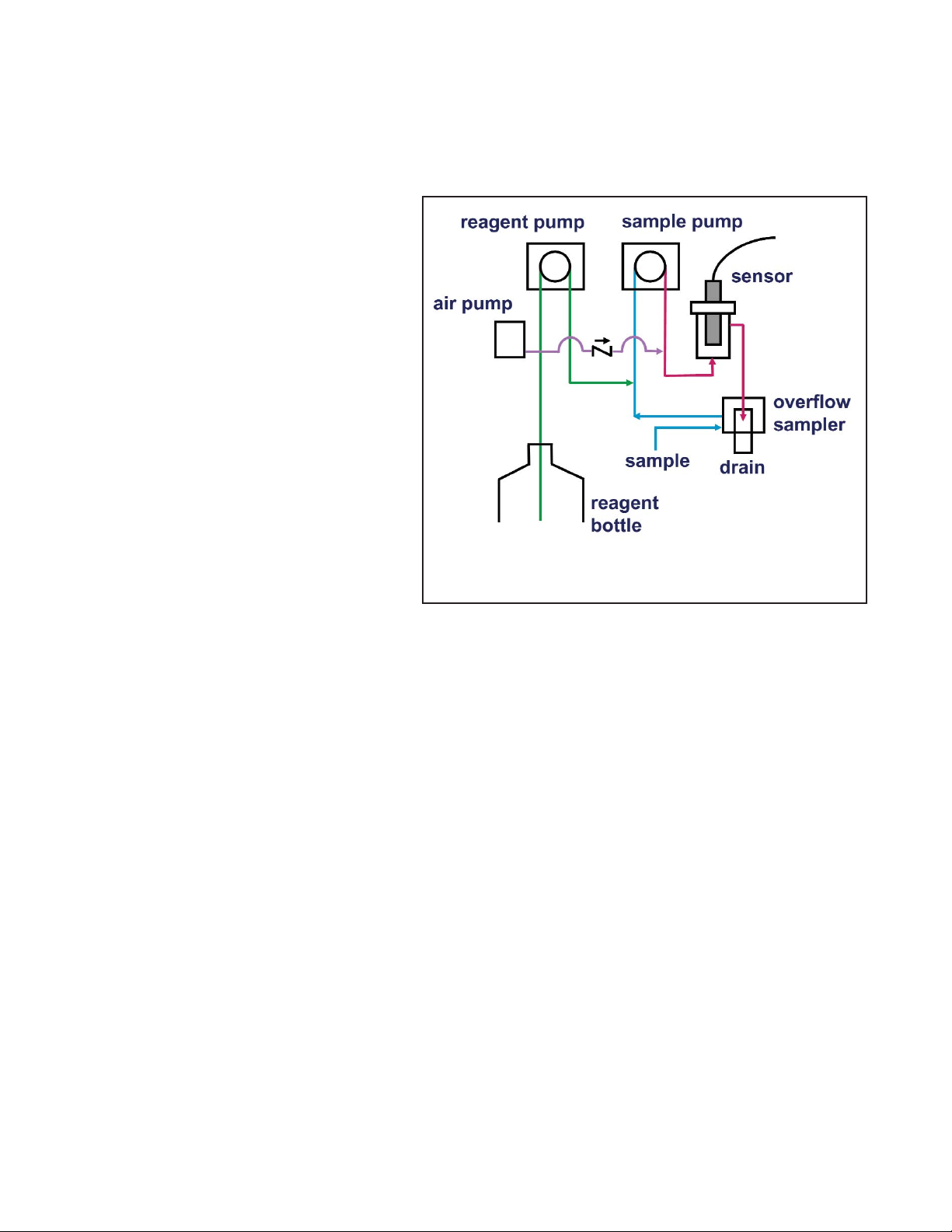
The total chlorine analyzer consists of a sample conditioning system, which injects the
reagent into the sample, and a sensor and
analyzer, which measure the amount of iodine
produced. Figure 2-1 shows the sample conditioning system. The sample enters the sample
conditioning enclosure and flows to an overflow sampler from which the sample pump
takes suction. Excess sample drains to waste.
At the same time, the reagent pump draws
reagent, a solution of potassium iodide in vinegar, from the reagent carboy and injects it into
the suction side of the sample pump. The sample and reagent mix as they pass through the
pump, and total chlorine in the sample is converted to the chemically equivalent amount of
iodine. The flow rates are 11 mL/min for the
sample and 0.2 mL/min for the reagent.
The treated sample next enters the flow cell. Bubbles injected into the flow cell produce turbulence, which
improves the stability of the reading. A membrane-covered amperometric sensor in the flow cell measures the
concentration of iodine. The analyzer receives the raw signal from the sensor and displays the concentration of
total chlorine. Display units are ppm (mg/L) chlorine as Cl2. The treated sample leaves the flow cell and drains to
waste along with the excess sample.
FIGURE 2-1. Schematic of Sample Conditioning
System and Analyzer.
Page 15
8
3.1 UNPACKING AND INSPECTION
Inspect the shipping containers. If there is damage, contact the shipper immediately for instructions. Save the
boxes. If there is no apparent damage, unpack the containers. Be sure all items shown on the packing list are present. If items are missing, notify Rosemount Analytical immediately.
3.2 INSTALLATION.
3.2.1 General Information
1. Although the analyzer and sample conditioning system are suitable for outdoor use, do not install them in direct
sunlight or in areas of extreme temperature.
2. Install the analyzer and sample conditioning system in an area where vibration and electromagnetic and radio
frequency interference are minimized or absent.
3. Keep the analyzer and sensor wiring at least one foot from high voltage conductors. Be sure there is easy
access to the analyzer and sample conditioning system.
4. The analyzer is suitable for panel, pipe or wall mounting. The sample conditioning enclosure must be mounted on a wall. Provide adequate room beneath the enclosure for the 5-gallon reagent carboy.
5. Be sure that the distance between the analyzer and sample conditioning cabinet does not exceed the length
of the sensor cable.
3.2.2 Install the Analyzer
1. Refer to the appropriate figure for installation details.
2. See Section 4.3 for wiring instructions.
SECTION 3. INSTALLATION
MODEL TCL SECTION 3
INSTALLATION
CAUTION
The TCL Total Chlorine analyzer is NOT
suitable for use in hazardous areas.
Type of Mounting Figure(s)
Wall 3-1
Pipe 3-2 and 3-3
Panel 3-4 and 3-5
Page 16
MODEL TCL SECTION 3
INSTALLATION
9
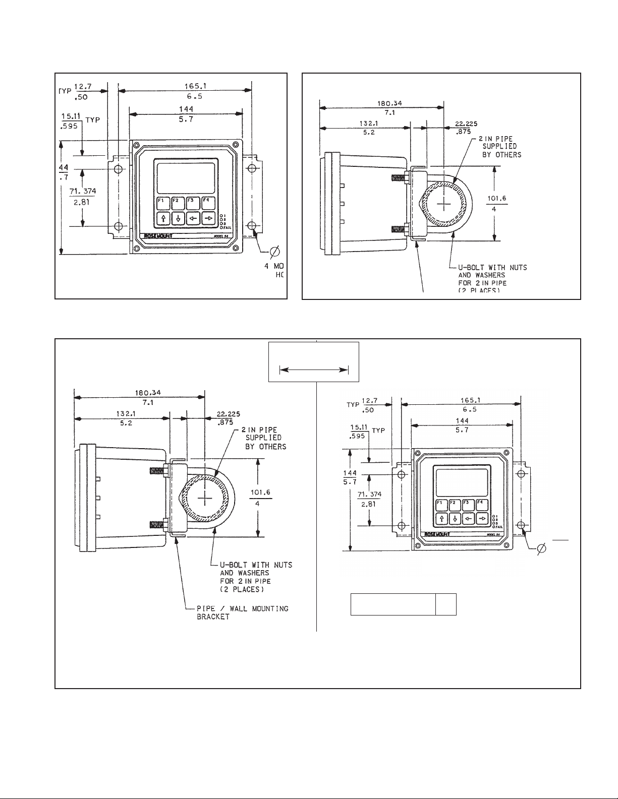
FIGURE 3-1. Wall Mounting
FIGURE 3-2. Pipe Mounting
9.52
.375
SIDE VIEW
FRONT VIEW
4 MOUNTING
HOLES
WHEN INCH AND METRIC DIMS
ARE GIVEN
MILLIMETER
INCH
PIPE MOUNTING PN 2002577 WALL MOUNTING
FIGURE 3-3. Pipe and Wall Mounting Dimensions
DWG. NO. REV.
40005402 E
Page 17
MODEL TCL SECTION 3
INSTALLATION
10
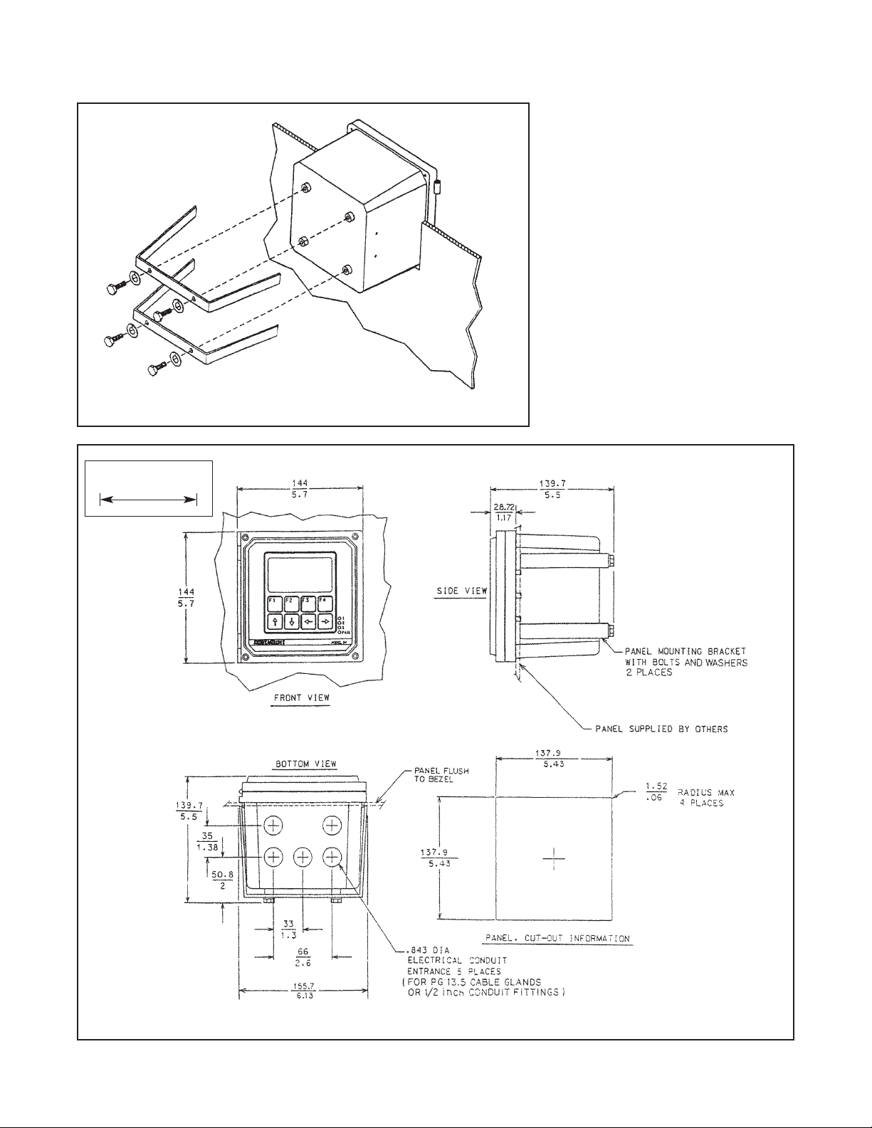
FIGURE 3-4. Panel Mounting
WHEN INCH AND METRIC DIMS
ARE GIVEN
MILLIMETER
INCH
FIGURE 3-5. Panel Mounting Dimensions
Page 18

11
MODEL TCL SECTION 3
INSTALLATION
3.2.3 Install the Sample Conditioning Enclosure
1. Refer to Figures 3-6 and 3-7 for installation details.
2. Connect the sample line to the sample conditioning system. Use ¼-inch OD hard plastic or stainless steel tubing. If dechlorinated water is being measured, provide a way of substituting a chlorinated water sample for the
dechlorinated sample. Chlorinated water is needed to calibrate the sensor and to check its response.
3. If a grab sample tap is not already available, install one in the process piping. Choose a point as close as possible to the sample line supplying the TCL. Be sure that opening the sample valve does not appreciably alter
the flow of sample to the instrument.
4. Connect the drain to a length of ¾-inch ID flexible plastic tubing. The sample must drain to open atmosphere.
5. Find the reagent tubing and fitting in the plastic bag taped to the inside of the enclosure door. Screw the
reagent fitting onto the bulkhead fitting at the bottom left of the enclosure. Pass the reagent tubing through the
hole in the carboy cap. Be sure the plastic weight will be inside the carboy when the cap is placed on the carboy. Attach the reagent tubing to the barbed connector. See Figure 3-8.
6. Place the blue plastic carboy beneath the enclosure. Place the weighted end of the reagent tubing inside the
carboy. To prepare reagent, see Section 5.2.
3.2.4 Install the Sensor
1. From inside the sample conditioning enclosure, thread the sensor cable through the gland on the upper left
side. Leave about one foot of cable inside the enclosure.
2. Wire the sensor to the analyzer. Refer to Section 4.3.
3. Remove the nut and adapter from the flow cell. Slip the nut over the end of the sensor. Thread the adapter
onto the sensor. Hand tighten only. Remove the protective cap from the end of the sensor.
4. Insert the sensor in the flow cell. Hand tighten the nut.
FIGURE 3-6. Installing the Sample Conditioning Enclosure
Page 19

MODEL TCL SECTION 3
INSTALLATION
12
FIGURE 3-7. TCL Case Dimensions
INCH
MILLIMETER
FIGURE 3-8. Attaching reagent tubing
Page 20
13
MODEL TCL SECTION 4
WIRING
SECTION 4. WIRING
4.1 GENERAL
WARNING
Electrical installation must conform to the National Electrical Code, all state and local codes, and all plant
codes and standards for electrical equipment. Electrical installation and wiring must be done by qualified
personnel.
The five holes in the bottom of the instrument case accept 1/2-in. strain relief connectors or conduit fittings. The
rear openings are for power and alarm relay wiring. The left front opening is for sensor wiring and the right front
opening is for analog output wiring. Seal unused openings with conduit plugs.
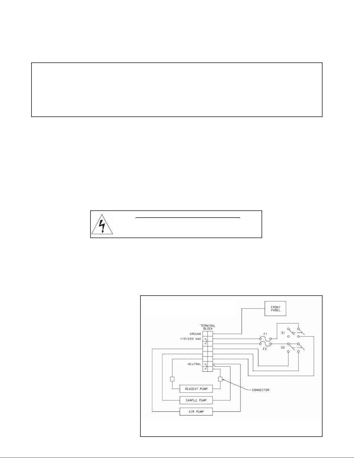
4.2 PROVIDE POWER TO THE SAMPLE CONDITIONING SYSTEM
NOTE
Provide a switch or breaker to disconnect the sample conditioning cabinet from
the main power supply. Install the switch or breaker near the unit and identify if as
the disconnecting device for the sample conditioning system.
1. Be sure the pump switches on the wiring access panel are in the off position.
2. Remove the four screws securing the wiring access panel. Pull the panel out of the way to reveal the power
terminal strip.
3. Insert the power cable through the
strain relief connection labeled
power (see Figure 3-7). Wire the
power cable to the terminal strip as
shown in Figure 4-1. Do not apply
230 Vac power to a 115 Vac TCL
(Model option -11). Doing so will
damage the instrument.
4. Leave the pump power switches
off until ready to start up the unit.
See Section 5.
NOTE
The Model 54eA analyzer leaves the factory configured for use with the Model 499ADO oxygen sensor.
Because a 499ADO sensor is NOT used in the TCL system, turn to Section 7.5 and configure the analyzer to read total chlorine before wiring the sensor to the analyzer. Operating the analyzer and sensor for
longer than five minutes while the analyzer is improperly configured will greatly increase the stabilization
time for the sensor.
Be sure to turn off power to the analyzer before wiring the sensor.
FIGURE 4-1. Power Wiring
WARNING: RISK OF ELECTRICAL SHOCK
AC connections and grounding must be in compliance with
UL 508 or local electrical code. DO NOT apply power to the
analyzer until all electrical connections are verified and secure.
Model option -11 115 Vac only
Model option -12 230 Vac only
Page 21
MODEL TCL SECTION 4
WIRING
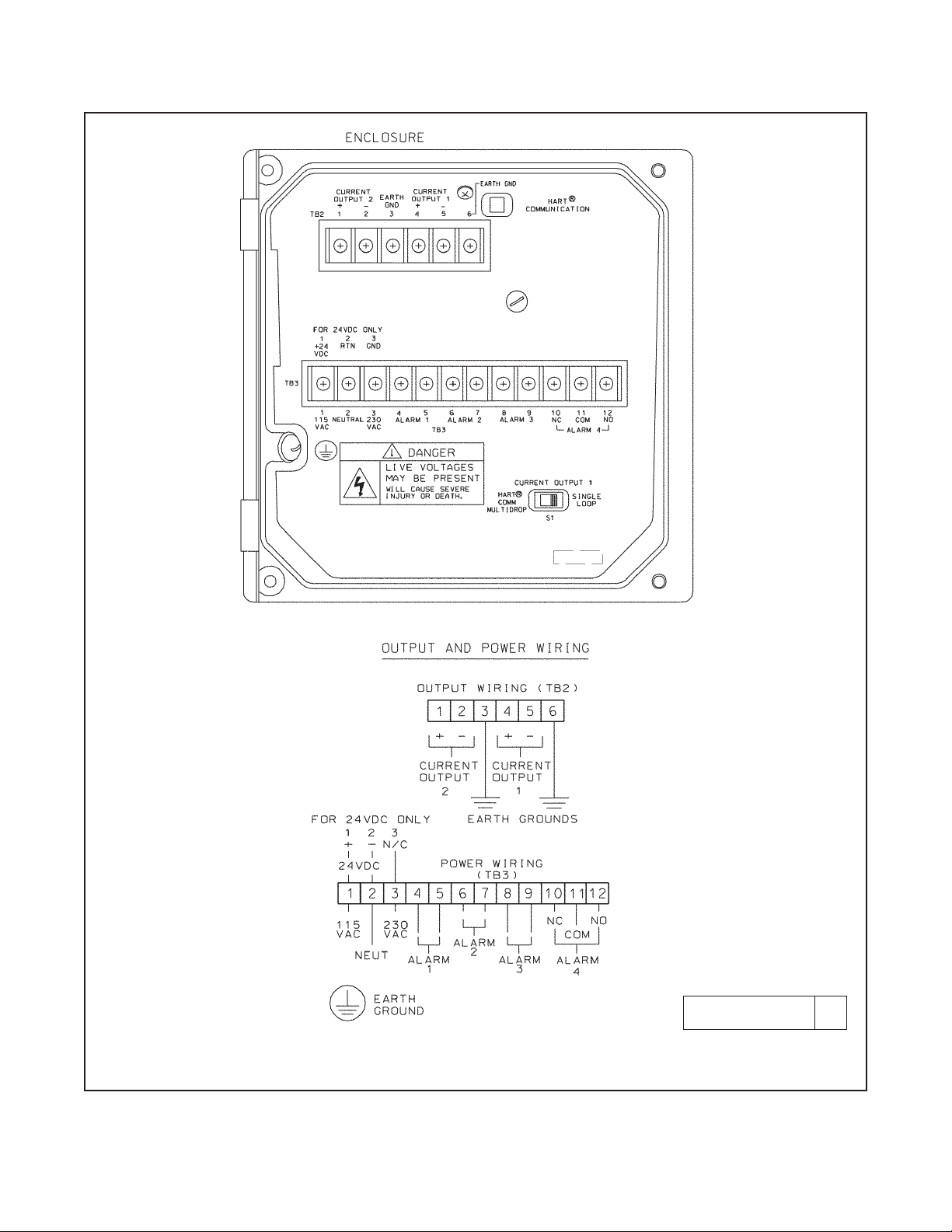
4.3 MAKE POWER, ALARM, OUTPUT AND SENSOR CONNECTIONS IN THE ANALYZER
Refer to Figure 4-2. Make power and alarm connections on TB3. Make analog output wiring connections on TB2. For
access to power and alarm terminals, loosen the screw holding the protective cover in place and remove the cover.
DANGER
Live voltages may be present.
Will cause severe injury or death.
Alarm contacts are dry (i.e., not powered) and are normally open. Refer to Section 1.0 for relay specifications.
For best EMI/RFI protection, shield the output cable and enclose it in an earth-grounded, rigid, metal conduit.
Connect the outer shield of the output cable to the earth ground connection on TB2 (see Figure 4-2).
Keep sensor and output signal wiring separate from power wiring. Do no run sensor and power cables in the same
conduit or close together in a cable tray.
AC wiring must be 14 gauge or greater. Be sure to connect earth ground from the power cable to the nearby
ground lug. A good earth ground is necessary for proper operation of the controller. Provide a switch or breaker to
disconnect the analyzer from the main power supply. Install the switch or breaker near the analyzer and label it as
the disconnecting device.
WARNING: RISK OF ELECTRICAL SHOCK
AC connections and grounding must comply with UL 508 or local electrical code. DO NOT apply
power to the analyzer until all electrical connections are verified and secure.
NOTE
The Model 54eA analyzer leaves the factory configured for use with the Model 499ADO oxygen
sensor. Because a 499ADO sensor is NOT used in the TCL system, turn to Section 7.5 and configure the analyzer to read total chlorine before wiring the sensor to the analyzer. Operating the
analyzer and sensor for longer than five minutes while the analyzer is improperly configured will
greatly increase the stabilization time for the sensor.
Be sure to turn off power to the analyzer before wiring the sensor.
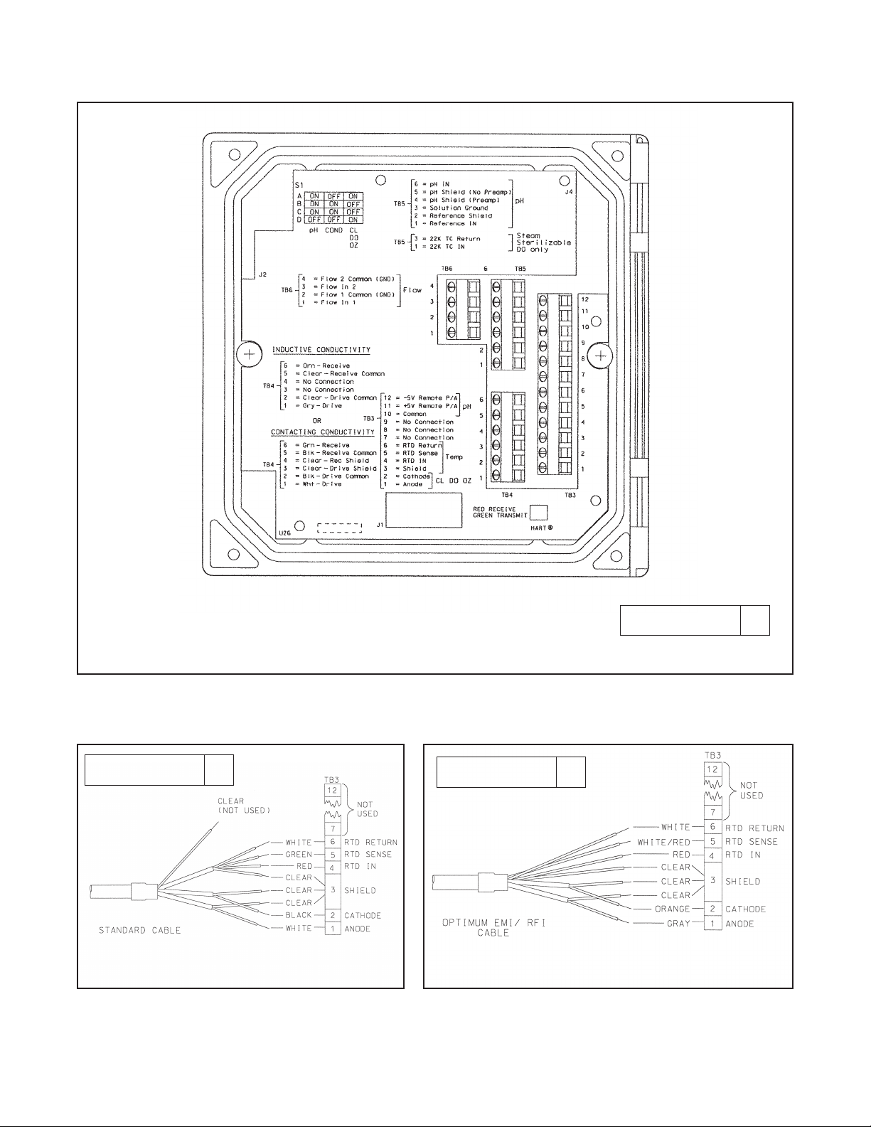
The wiring label, which is shown in Figure 4-3, is a general purpose label. It has wiring information concerning
other sensors, for example, contacting and inductive conductivity sensors, that can be used with the 54e instrument platform. For total chlorine measurements, only TB3 is used.
Refer to Figures 4-4 and 4-5 for sensor wiring. Use the pigtail wire and wire nuts provided with the sensor when
more than one wire must be attached to a single terminal
14
Page 22
15
MODEL TCL SECTION 4
WIRING
FIGURE 4-2. Power Input and Relay Output Wiring for Model 54eA
DWG. NO. REV.
454EPH02 D
Page 23
MODEL TCL SECTION 4
WIRING
FIGURE 4-4. Total chlorine sensor
(499ACL-02) with standard cable.
FIGURE 4-5. Total chlorine sensor (499ACL-02)
with optimum EMI/RFI cable or Variopol cable.
FIGURE 4-3. Wiring Label
DWG. NO. REV.
40054e03 A
DWG. NO. REV.
40499A23 A
DWG. NO. REV.
40499A24 A
16
Page 24
MODEL TCL SECTION 5
START-UP
SECTION 5. START-UP
5.1 PREPARE THE REAGENT
1. DO NOT PREPARE THE SOLUTION UNTIL READY TO USE.
2. Position the blue plastic carboy under the sample conditioning cabinet. Unscrew the cap and reagent tube
assembly.
3. Add the potassium iodide reagent to the carboy. See the table.
4. Add five gallons (19 L) of distilled white vinegar one gallon (4 L) at a time. Swirl the carboy after each addition
5. Screw the cap on the carboy. Be sure the reagent uptake tube extends to the bottom of the carboy.
6. Connect the reagent tube to the small fitting on the bottom left hand side of the enclosure.
NOTE
The shelf life of the potassium iodide vinegar solution is at least two months if stored in the blue
carboy. Do not store the reagent in a container other than the blue carboy. The reagent is sensitive to sunlight, which the blue carboy effectively blocks.
5.2 ZERO THE SENSOR
1. Place the sensor in a beaker of deionized water or simply place the sensor in air.
2. Let the sensor operate until the sensor current is stable, then zero the sensor. See Section 8.3.2 for detailed
instructions.
5.3 START SAMPLE FLOW
Adjust the sample flow until a slow stream of liquid is running down the inside tube of the sampling cup.
5.4 BEGIN OPERATION AND CALIBRATE THE SENSOR
1. Turn on the reagent and sample pump switches. Observe that liquid begins to fill the flow cell. The sample flow
is about 11 mL/min, so the flow cell will fill rather slowly. Also observe that the air pump is operating. The pump
will produce very vigorous bubbling in the flow cell.
2. Once the flow of reagent starts, it takes about two minutes for the reagent to reach the flow cell. If the concentration of total chlorine in the sample is greater than about 0.5 ppm, the treated sample in the flow cell will
be pale yellow. Sample containing more chlorine will be dark yellow.
3. Monitor the sensor current. Once the reading is stable, calibrate the unit. See Section 9.3.3 for detailed instructions. It may take thirty minutes or longer for the reading to stabilize when the sensor is first put in service.
WARNING
The reagent contains potassium iodide dissolved in distilled vinegar or 5%
acetic acid. Avoid contact with skin and eyes. Wash thoroughly after using.
NOTE
Complete Section 4 before starting this section.
Expected range, Amount of KI needed Part number
ppm as Cl2 per 5 gal (19 L) of vinegar
0 – 5 ppm 25 grams 24164-00
0 – 10 ppm 50 grams 24164-01
0 – 20 ppm 2 x 50 grams 24164-01
171818
Page 25
MODEL TCL SECTION 6
DISPLAY AND OPERATION
SECTION 6. DISPLAY AND OPERATION
6.1 GENERAL DESCRIPTION
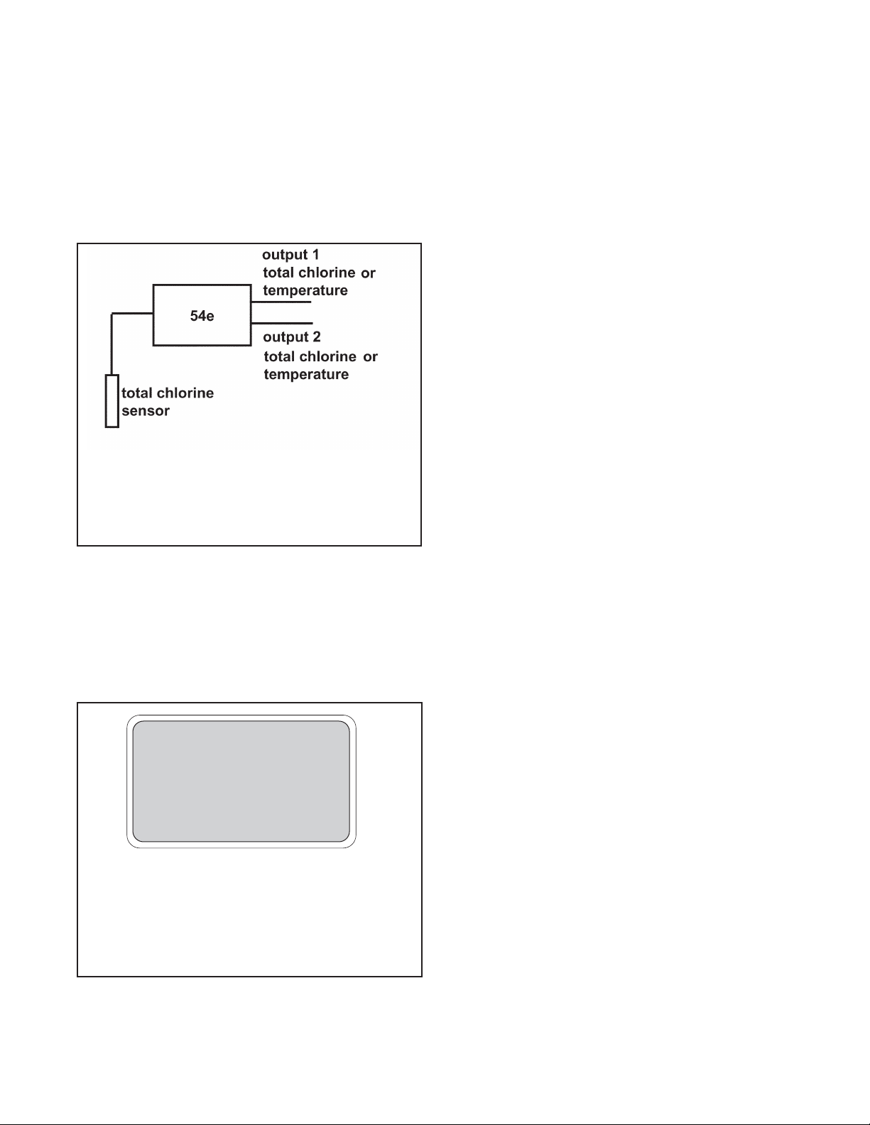
The 54eA analyzer/controller is a single input, dual output instrument. Figure 6-1 shows how the instrument
inputs and outputs can be configured for total chlorine.
In addition to PID control, the 54eA controller can be
used for time proportional control (TPC). TPC control
uses the alarm relays.
6.2 DISPLAY
Figure 6-2 shows the main display.
6.3 KEY FUNCTIONS AND CONTROLS
The keys labeled F1, F2, F3, and F4 are multi-function.
The function appears in the main display just above the
key. For example, F1 is usually labeled Exit and F4
may be labeled Edit, Save, or Enter.
1. To enter the main menu, press any key.
2. Use the and keys to move the cursor to the
desired sub-menu. The position of the cursor is
shown in reverse video.
NOTE
When the last item of a menu has been
reached, the cursor will be on the third line
of the display. If the cursor is on the second
line of the display more items remain.
Continue pressing the key.
3. Press Enter (F4) to access a sub-menu or an item
in a sub-menu.
4. To change a number or a setting press Edit (F4).
The display will change to show the cursor on the
first digit or on a + or - sign. Use the and keys
to increase or decrease a digit or to toggle the +
and - signs. Use the and keys to move the
cursor left and right.
5. If an entire number or a word is highlighted, use the
and keys to scroll through the list of choices.
6. To store a number or setting in memory, press
Save (F4).
7. To leave without storing changes, press Esc (F3).
8. To leave and return to the previous screen, press
Exit (F1).
9. To end a calibration step and leave the previous
calibration in place, press Abort (F1).
10. Occasionally, information screens will appear. To
leave the information screen and move to the next
screen press Cont (F3).
6.4 ALARM STATUS
Green LEDs (labeled 1, 2, and 3) indicate when alarm
relays 1, 2, and 3 are energized. The fourth relay indicates a fault condition. When a fault occurs, the red
LED (labeled FAIL) lights up, a descriptive error message appears, and the outputs and alarm relays act as
described in Section 7.6 and Section 7.7 under fault
value.
The red LED also indicates when the interval timer routine is activated and when the time limit has been
reached on a feed limit timer. For more information on
these subjects, see Section 7.7.
FIGURE 6-1. Configuration of Outputs
for Total Chlorine
Outputs can be assigned to total chlorine or to
temperature. The outputs can be configured as
either linear (4-20 mA) or PID outputs.
FIGURE 6-2. Main Display Screen
The total chlorine measurement is always displayed continuously in large numerals. The temperature and output
current are always displayed on the second line of the main
display. The third line can be configured by the user. In the
example, the third line shows the alarm 1 setpoint and the
total chlorine sensor current in nA.
1.00 ppm
26.2°C. 12.00 mA
AL1: 0.50 I: 340 nA
Page 26

19
MODEL TCL SECTION 7
SOFTWARE CONFIGURATION
SECTION 7. SOFTWARE CONFIGURATION
The instrument is configured at the factory to measure oxygen. To change the measurement to total
chlorine, see Section 7.5.
Figure 7-1 is an outline of the menu structure.
Table 7-1 lists the default settings and the range of choices available for each setting. Only settings related to
total chlorine are shown. To reduce the chance of error when configuring the controller the first time, enter settings in the order shown in the table.
TABLE 7-1. Program Settings List
Continued on the following page
ITEM CHOICES FACTORY SETTINGS
SETPOINTS
A. Alarms (Section 7.1)
1. Alarm 1 (low action)
a. if chlorine -9999 to 9999 ppm 0 ppm
b. if temperature -5 to 130°C 0.1°C
2. Alarm 2 (high action)
a. if chlorine -9999 to 9999 ppm 20 ppm
b. if temperature -5 to 130°C 130°C
3. Alarm 3 See alarm 2 See alarm 2
B. Outputs (Section 7.2 and 7.3)
1. Output 1 or 2: 4 mA setting
a. if chlorine -9999 to 9999 ppm 0 ppm
b. if temperature -5 to 130°C 0.1°C
2. Output 1 or 2: 20 mA setting
a. if chlorine -9999 to 9999 ppm 20 ppm
b. if temperature -5 to 130°C 130°C
3. Setpoint (PID)
a. if chlorine -9999 to 9999 ppm 1.00 ppm
b if temperature -5 to 130°C 25°C
A. Display options (Section 7.5)
1. Measurement Oxygen, ozone, free chlorine, total chlorine, monochloramine Oxygen
2. Temperature units °C or °F °C
3. Output 1 mA or % of full scale mA
4. Output 2 mA or % of full scale mA
5. Language English, Français, Español, Deutsch, Italiano English
6. Main display left See section 6.5 Sensor current
7. Main display right See section 6.5 Output 1 current
8 Display contrast 00-99 (darkest) 50
9. Test timeout On or off On
10. Timeout value 1 to 60 min 10 min
Page 27

20
MODEL TCL SECTION 7
SOFTWARE CONFIGURATION
Continued on the following page
ITEM CHOICES FACTORY SETTINGS
CONFIGURE
B Outputs (Section 7.6)
1. Output 1 Control
a. Measurement Oxygen, chlorine, ozone, pH, or temperature Oxygen
b. Control Normal or PID Normal
2. Output 1 Setup (normal)
a. Current 4-20 mA or 0-20 mA 4-20 mA
b. Dampening 0-299 sec 0 sec
c. Hold mode Hold last value or go to fixed value Hold last value
d. Fixed hold value 0-22 mA 21 mA
e. Fault value 0-22 mA 22 mA
3. Output 1 Setup (PID)
a. Proportional 0 to 299.9% 100 %
b. Integral 0 to 2999 sec 0 sec
c. Derivative 0 to 299.9% 0/0%
4. Output 2 Control
a. Measurement Oxygen, chlorine, ozone, pH, or temperature Temperature
b. Control Normal or PID Normal
5. Output 2 Setup (normal) See output 1 See output 1
6. Output 2 Setup (PID) See output 1 See output 1
7. Hold feature Enable, disable, or 20 min timeout Disable
C. Alarms (Section 7.7)
1. Alarm 1 Control
a. Activation method Chlorine or temperature Chlorine
b. Control mode Normal or TPC Normal
2. Alarm 1 setup (normal)
a. Configuration Low, high, or off High
b. Hysteresis
if chlorine -9999 to 9999 ppm 0 ppm
if temperature 0 to 10°C 0.1°C
c. Delay time 0-99 sec 0 sec
d. Relay fault none, open, closed None
3. Alarm 1 setup (TPC)
a. Setpoint
if chlorine -9999 to 9999 ppm 1.0 ppm
if temperature -5 to 130°C 25°C
b. Proportional 0 to 299.9% 100 %
c. Integral 0 to 2999 sec 0 sec
d. Derivative 0 to 299.9% 0.0%
e. Time period 10 to 2999 sec 30 sec
f. LRV (100% on)
if chlorine -9999 to 9999 ppm 0 ppm
if temperature -5 to 130°C 0°C
g. URV (100% off)
if chlorine -9999 to 9999 ppm 2 ppm
if temperature -5 to 130°C 100°C
h. Relay fault None, open, or closed None
TABLE 7-1. Program Settings List (continued)
Page 28

MODEL TCL SECTION 7
SOFTWARE CONFIGURATION
ITEM CHOICES FACTORY SETTINGS
CONFIGURE (continued)
C. Alarms (Section 7.7) (continued)
4. Alarm 2 Control
a. Activation method Chlorine, temperature Chlorine
b. Control mode Normal or TPC Normal
5. Alarm 2 setup (normal)
a. Configuration Low, high, or off Low
Rest of alarm 2 setup is the same as alarm 1
6. Alarm 3 control and setup is the same as alarm 1
7. Alarm 4 control
Alarm Fault or off Fault
8. Feed limit timer
a. Feed limit Disable, alarm 1, alarm 2, or alarm 3 Disable
b. Timeout value 0 to 10,800 sec 600 sec
9. Interval timer
a. Select alarm Disable, alarm 1, alarm 2, or alarm 3 Disable
b. Interval time 0 to 999.9 hr 24.0 hr
c. Repeats 1 to 60 1
d. On time 0 to 2999 sec 120 sec
e. Off time 0 to 2999 sec 1 sec
f. Recovery time 0 to 999 sec 600 sec
D. Temperature compensation (Section 7.9)
1. Temperature compensation Auto or manual Auto
2. Manual temperature -15 to 130°C 25°C
E. Noise Reduction (section 7.10)
Noise rejection 50 or 60 Hz 60 Hz
F. Main sensor calibration (Section 7.11)
1. Stabilize reading 0 to 9999 ppm 0.05 ppm
2. Stabilize time 0 - 30 sec 10 sec
3. Sensor zero stabilization value
4. Dual range calibration Enable or disable disable
G. Security (Section 7.13)
1. Lock all 000-999 (000 disables) 000
2. Lock program 000-999 (000 disables) 000
3. Lock configuration 000-999 (000 disables) 000
TABLE 7-1. Program Settings List (continued)
21
Page 29

22
MODEL TCL SECTION 7
SOFTWARE CONFIGURATION
FIGURE 7-1. Menu Tree for the 54eA Controller
Calibrate
Program (see page 24)
Diagnostic Variables
Main
Menu
Calibrate main sensor
Zero main sensor
Adjust temperature
Main measurement
Main sensor current
Sensitivity (µA/ppm)
Zero current
Noise rejection
Software version
Device ID
Output trim
Page 30

MODEL TCL SECTION 7
SOFTWARE CONFIGURATION
Program
Calibrate (see page 22)
Diagnostic Variable (see page 22)
Main
Menu
Alarms 1, 2, and 3 setpoints
4 mA or 0 mA
20 mA
Present output current
Alarm Setpoints
Output setpoints
Test output 1 or 2
Test alarm 1, 2, 3, or 4
Simulated tests
Configure
Display
To ta l
Chlorine
Outputs
Output 1 and 2
control
Measurement: main snr, pH, temp.
Control mode: normal, PID
Output 1 and 2
setup
Range (0-20 or 4-20 mA)
Dampen*
Hold - keep last value
Hold - go to specified value
Fault
Setpoint, proportional, integral
Derivative**
Hold feature setup
*Normal only
**PID only
Alarms
Alarm 1, 2, & 3
control
Measurement: main snr, pH, temp.
Control mode: normal, TPC
Alarm 1, 2, & 3
setup
Alarm: High, low, or off*
Setpoint
Hysteresis*
Delay*
Time period, URV, LRV**
Relay default
Interval timer
Timer: Alarm 1, 2, or 3 or disable
Interval
Repeats
On time
Off time
Recovery time
Alarm 4 setup
Feed limit timer
Feed limit: Alarm 1, 2, or 3 or disable
Timeout
*Normal only **TPC only
Continued on page 24
FIGURE 7-1. Menu Tree for the 54eA Controller
(continued)
°C or °F
Output 1 (mA or %FS)
Output 2 (mA or %FS)
Language
Line 3 display
Display contrast
Timeout (on or off)
Timeout - limit
Polling address
23
Page 31

24
MODEL TCL SECTION 7
SOFTWARE CONFIGURATION
FIGURE 7-1. Menu Tree for the 54eA Controller (continued)
Display (see page 23)
Outputs (see page 23)
Alarms (see page 23)
Program
Calibrate (see page 22)
Diagnostic Variable (see page 22)
Main
Menu
Alarm Setpoints (see page 23)
Output setpoints
(see page 23)
Simulated tests
(see page 23)
Configure
Temperature
Temperature comp: auto or manual
Units: °C or °F
Noise
Rejection
Noise rejection: 50 or 60 Hz
Main sensor cal
Stabilize conc’n
Stabilize time
Security
Lock all
Lock program
Lock configure
Page 32

7.1 CHANGING ALARM SETPOINTS
2. Press any key to enter the main menu. Move the cursor to "Program"
and press Enter (F4).
3. Press Enter (F4).
4. Move the cursor to the desired alarm and press Enter (F4).
5. The screen appearing at this point depends on how the alarm was
configured.
6. If the alarm is a normal (i.e., not TPC) alarm, a screen like the one
shown will appear. The alarm is a low alarm and the setpoint is 0.00
ppm. Press Edit (F4). Use the arrow keys to change the setpoint.
Press Save (F4) to store the new value. Press Exit (F1) to return to
the screen in step 4. Choose a new alarm.
7. If the alarm is TPC, a screen like the one shown will appear. The setpoint is +1.000 ppm. Press Edit (F4). Use the arrow keys to change
the setpoint. Press Save (F4) to store the new value. Press Exit (F1)
to return to the screen in step 4. Choose a new alarm.
Alarm setpoints
Output setpoints
Simulate tests
Exit Enter
Alarm 1 setpoint
Alarm 2 setpoint
Alarm 3 setpoint
Exit Enter
Alarm Low : 0.000 ppm
Exit Edit
Setpoint : 1.000 ppm
Exit Edit
1. Before changing alarm setpoints, be sure that alarms are properly configured. See Section 7.7.
MODEL TCL SECTION 7
SOFTWARE CONFIGURATION
25
Page 33

26
MODEL TCL SECTION 7
SOFTWARE CONFIGURATION
7.2 RANGING THE OUTPUTS
2. Press any key to enter the main menu. Move the cursor to "Program"
and press Enter (F4).
3. Move the cursor to "Output setpoints" and press Enter (F4).
4. Move the cursor to the desired output and press Enter (F4).
5. This screen confirms that changes to output 1 are going to be made.
Use caution. Changes may degrade process control. Press Cont
(F3) to continue. Otherwise, press Abort (F1).
6. This screen shows the present settings for Output 1. If the output
was configured to be 0-20 mA, the first line will show "0mA" instead
of "4mA". The live current output is shown on the third line.
Move the cursor to the desired line and press Edit (F4). Use the
arrow keys to change the setpoint. Press Save (F4) to store the new
value.
Press Exit (F1) to return to the screen in step 4. Choose the other
output and continue.
Output 1 setpoints
Output 2 setpoints
Exit Enter
Alarm setpoints
Output setpoints
Simulated test
Exit Enter
CAUTION: Current
Output 1 will be
affected.
Abort Cont
1. Ranging the outputs means assigning values to the low (0 or 4 mA) and high (20 mA) outputs. Before rang-
ing the outputs, be sure the outputs are properly configured. See Section 7.6.
4 mA : 0.00 ppm
20 mA: 20.00 ppm
Output 1: 12.00 mA
Exit Edit
Page 34

MODEL TCL SECTION 7
SOFTWARE CONFIGURATION
7.3 CHANGING OUTPUT SETPOINTS (PID ONLY)
2. Press any key to enter the main menu. Move the cursor to "Program"
and press Enter (F4).
3. Move the cursor to "Output setpoints" and press Enter (F4).
4. Move the cursor to the desired output and press Enter (F4).
5. This screen confirms that changes to output 1 are going to be made.
Use caution. Changes may degrade process control. Press Cont
(F3) to continue. Otherwise, press Abort (F1).
6. This screen shows the present settings for Output 1. If the output
was configured to be 0-20 mA, the second line will show "0mA"
instead of "4mA". The live current output is shown on the fourth line.
Press the key once to view the live output.
Move the cursor to the desired line and press Edit (F4). Use the
arrow keys to change the value. Press Save (F4) to store the new
value.
Press Exit (F1) to return to the screen in step 4. Choose the other
output and continue.
Setpoint : 1.000 ppm
4mA: 0.000 ppm
20mA: 10.00 ppm
Exit Edit
1. This section describes how to assign the setpoint and the upper and lower range values (URV and LRV) when
the 54eA is being used for PID control. Assign the LRV to 4 mA and the URV to 20 mA. The LRV is the deviation from the setpoint that will result in a 4 mA output. The URV is the deviation from the setpoint that will
result in a 20 mA output.
Example: The setpoint is 1.00 ppm. The URV is +0.50 and the LRV is 0.00. If the present reading is 1.20 ppm,
the output will be (1.20 - 1.00)/(0.50 - 0.00) or 40% of the range (10.40 mA). If the present reading is 1.50 ppm,
the output will be (1.50 - 1.00)/(0.50 - 0.00) or 100% of the range (20.00 mA). If the present reading is less
than the setpoint, the output will be 4 mA.
The control setpoint is usually the condition where the output current is a minimum. The P and I control calculations use the setpoint to adjust the output to the desired level based on the parameters established in
Section 7.6.
To configure the controller for PID control, see Section 7.6.
Alarm setpoints
Output setpoints
Simulated test
Exit Enter
CAUTION: Current
Output 1 will be
affected.
Abort Cont
Output 1 setpoints
Output 2 setpoints
Exit Enter
27
Page 35

28
MODEL TCL SECTION 7
SOFTWARE CONFIGURATION
7.4 TESTING OUTPUTS AND ALARMS
2. Press any key to enter the main menu. Move the cursor to "Program"
and press Enter (F4).
3. Move the cursor to "Simulated tests" and press Enter (F4).
4. Move the cursor to the desired output or alarm. Both outputs and all
four alarms can be tested. Press Enter (F4).
A screen will appear warning that the output or alarm will change.
Press Cont (F3) to continue. Press Abort (F1) to cancel the simulation.
5. This screen appears when an output is being simulated. To change
the simulation current, press Edit (F4). Use the arrow keys to change
the current to the desired value. Press Test (F4), then Esc (F3).
The simulated current will be generated for 10 minutes, then the output returns to normal operation. To change the timeout to a different
value see Section 7.5.
To end the simulation at any time, press Exit (F1).
6. This screen appears when an alarm is being simulated. To change
the state of the relay, press Edit (F4). Use the or keys to change
from open to closed. Press Test (F4), then Esc (F3).
The alarm will be simulated for 10 minutes, then the alarm returns to
normal operation. To change the timeout to a different value, see
Section 7.5.
To end the simulation at any time, press Exit (F1).
Output setpoints
Simulated tests
Configure
Exit Enter
Test output 1
Test output 2
Test alarm 1
Exit Enter
Test output 1: 10.00 mA
Simulating output1
Exit Edit
Test alarm 1: Open
Simulating alarm1
Exit Edit
1. For testing purposes, the controller can be programmed to generate simulated outputs and to activate and
deactivate alarms.
Page 36

Output setpoints
Simulated tests
Configure
Exit Enter
MODEL TCL SECTION 7
SOFTWARE CONFIGURATION
7.5 CHOOSING DISPLAY OPTIONS
3. Press any key to enter the main menu. Move the cursor to "Program"
and press Enter (F4).
4. Move the cursor to "Configure" and press Enter (F4).
5. With the cursor on "Display", press Enter (F4).
6. A screen showing the present main measurement will appear. To
change the measurement to total chlorine, press Edit (F4), then use
the key to scroll through the choices until total chlorine is highlighted. Press Save (F4) to store the setting.
A screen will appear warning that if the measurement is changed, the
analyzer will return to factory default settings. Press Cont (F3) to continue. Press Abort (F1) to cancel the change.
continued on following page
Display
Outputs
Alarms
Exit Enter
1. The 54eA controller can be used with any amperometric sensor manufactured by Rosemount Analytical. The
default sensor is oxygen. In order to use the controller with a total chlorine sensor, the sensor identification
must be changed.
2. The display menu also lets the user customize the third line in the display, change timeout values, choose a
language other than English, and change the display contrast.
29
Page 37

30
MODEL TCL SECTION 7
SOFTWARE CONFIGURATION
7.5 CHOOSING DISPLAY OPTIONS (CONTINUED)
7. Set the remainder of the display parameters. Use the and keys
to choose the desired parameter. Then press Edit (F4). Use the
key to move the cursor to the desired selection. Press Save (F4) to
store.
SECURITY CAUTION
The controller uses the timeout value to activate security. Once
the controller is unlocked by entering a security code, security
will not re-activate until a display timeout occurs. If timeout has
been turned off, security will never reactivate.
Temp units: °C
Output 1: mA
Output 2: mA
Exit Edit
Language: English
Display left: I
Display right: Out 2
Exit Edit
Display contrast: 40
Timeout: On
Timeout value: 10 min
Exit Edit
Temp units °C or °F
Output 1 mA or % of full scale
Output 2 mA or % of full scale
Language English, Français, Español, Deutsch, Italiano
Display left sensor current (I), alarm 1 setpoint (no units), alarm
3 setpoint (no units), or blank
Display right sensor current (I), alarm 2 setpoint (no units), alarm
3 setpoint (no units), output 2, or blank
Display Contrast 00 (lightest)-99 (darkest); the display contrast
changes as the number changes
Timeout Timeout returns the display from any other screen
to the main display if no key is pressed before the
timeout value is exceeded.
Polling address Identifies controller in multi-drop HART applications.
Timeout value
Page 38

MODEL TCL SECTION 7
SOFTWARE CONFIGURATION
7.6 CHANGING OUTPUT PARAMETERS
3. Press any key to enter the main menu. Move the cursor to "Program"
and press Enter (F4).
4. Move the cursor to "Configure" and press Enter (F4).
5. Move the cursor to "Outputs" and press Enter (F4).
6. Five menu headers relate to outputs. Each output has a control header and a setup header. The fifth header allows the output hold feature
to be configured.
Always configure the control parameters BEFORE making
changes in the output setup.
To access a header, move the cursor to the desired header and press
Enter (F4).
7. Output Control Settings:
a. Move the cursor to the desired output control header. Press Enter
(F4).
b. With the cursor on "Output Measurement" press Enter (F4).
c. Press Edit (F4).
d. Use the key to scroll through the choices: "Process" or
"Temperature". "Process" means the measurement made by the
Output 1 control
Output 1 setup
Output 2 control
Exit Enter
Output Measurement
Control Mode
Exit Enter
Output : Process
Exit Edit
Display
Outputs
Alarms
Exit Enter
1. This section describes how to configure the controller outputs. Outputs can be configured to represent total
chlorine or temperature.
2. The output can be configured as either a normal or PID output. Normal means the output current is directly
proportional to the measurement assigned to the output. PID means the output is used for PID control.
Output setpoints
Simulated tests
Configure
Exit Enter
31
Page 39

32
MODEL TCL SECTION 7
SOFTWARE CONFIGURATION
7.6 CHANGING OUTPUT PARAMETERS (continued)
main sensor (total chlorine). Press Save (F4) to store the selection.
e. The display returns to the “Output: Process” screen. Press Exit
(F1). The display returns to the “Output Measurement” screen.
Move the cursor to "Control mode" and press Enter (F4).
f. Press Edit (F4). Use the key to toggle between "Normal" and
"PID". Press Save (F4) to store the selection.
8. Output setup for normal outputs:
a. Move the cursor to the desired output setup and press Enter (F4).
b. Use the and arrow keys to move the cursor to the desired
parameter. Press Edit (F4). Use the arrow keys to change the setting to the desired value and press Save(F4) to store the value.
Range: Choose 4-20 mA or 0-20 mA.
Dampen: Dampening averages the output current, thus smooth-
ing out a noisy reading. Higher values provide more smoothing
but increase the response time of the output.
Hold and Fixed Hold: If the analyzer is placed in hold, the outputs will either remain at the last value or go to a fixed value
selected by the user. The fixed value must be between 0 and
22.00 mA.
Fault: If the analyzer detects a fault, the output will signal the fault
by going to a user-selected current between 0 and 22.00 mA.
For allowed values, see Table 7-1.
9. Output setup for PID outputs:
a. Move the cursor to the desired output setup and press Enter (F4).
b. Use the and keys to move the cursor to the desired param-
eter. Press Edit (F4). Use the arrow keys to change the setting to
the desired value and press Save (F4) to store the value.
Setpoint: Setpoint is usually the value at which the process is
being controlled. Typically, the output will be 4 mA (or 0 mA) when
the value is near the setpoint.
Ctrl mode : Normal
Exit Edit
Range : 4-20 mA
Dampen: 0 sec
Hold: Last Value
Exit Edit
Output 1 Control
Output 1 Setup
Output 2 Control
Exit Enter
Output 1 Control
Output 1 Setup
Output 2 Control
Exit Enter
Setpoint : 1.000 ppm
Proportional: 100.0%
Integral: 0 sec
Exit Edit
Page 40

MODEL TCL SECTION 7
SOFTWARE CONFIGURATION
Proportional: Proportional is the same as proportional band and
is the range over which control is being used. It is the opposite of
process gain. Smaller values provide tighter control.
Integral: Integral is the number of seconds over which deviations from the setpoint are integrated to remove continuing offsets. Smaller values provide higher response.
Derivative: Derivative is a form of control that resists all changes
in readings. Higher readings increase the derivative function. To
prevent process oscillation, use caution in setting the derivative
value.
Range: Choose 4-20 mA or 0-20 mA.
For an explanation of Hold, Fixed Hold, and Fault, see step 8b
above.
For allowed values, see Table 7-1.
For more information using PID control, see Section 11.0.
10. Hold setup.
a. Move the cursor to "Hold feature setup" and press Enter (F4).
b. Press Edit (F4). Use the to scroll through the choices: "Disable
feature", "Enable feature", and "20 min timeout". If "20 min timeout" is selected, hold mode will automatically disengage after
being on for 20 minutes.
NOTE
Selecting "Enable hold" or "20-min timeout" does not put
the controller in hold. It only allows the user to put the
controller in hold when the controller is in calibrate mode.
11. Using hold.
If hold was enabled in step 10 above, the hold screen will appear as
soon as the user enters the Calibrate menu. To activate Hold, press
Edit (F4). Use the key to change Off to On and press Save (F4).
"Hold Mode Activated" will be displayed. Outputs and relays will go to
the values programmed in step 8b.
"Hold Mode Activated" will continue to flash in the main display even
after the user has left the Calibrate menu. To deactivate hold, enter
the Calibrate menu and press Edit (F4). Use the key to change On
to Off and press Save (F4). Press Exit (F1) twice to return to the main
display.
Output 2 control
Output 2 setup
Hold feature setup
Exit Enter
7.6 CHANGING OUTPUT PARAMETERS (continued)
33
Page 41

34
MODEL TCL SECTION 7
SOFTWARE CONFIGURATION
7.7 CHANGING ALARM PARAMETERS
3. Press any key to enter the main menu. Move the cursor to "Program"
and press Enter (F4).
4. Move the cursor to "Configure" and press Enter (F4).
5. Move the cursor to "Alarms" and press Enter (F4).
6. Nine menu headers relate to alarms. Alarms 1, 2 and 3, each have a
control header and a setup header. Alarm 4 has only a setup header.
The eighth menu header is for configuring the feed limit timer, and the
ninth menu header is for configuring the interval timer.
Always configure the control parameters BEFORE making
changes in the alarm setup.
To access a header, move the cursor to the desired header and press
Enter (F4).
7. Alarm Control Settings:
a. Move the cursor to the desired output control header. Press Enter
(F4).
b. With the cursor on "Activation method" press Enter (F4).
Alarm 1 control
Alarm 1 setup
Alarm 2 control
Exit Enter
Outputs
Alarms
pH
Exit Enter
Output setpoints
Simulated tests
Configure
Exit Enter
1. This section describes how to configure the controller alarms. Alarms 1, 2, and 3 can be assigned to the main
measurement (total chlorine) or temperature. In addition, alarm 1, 2, or 3 can be configured as a feed limit
timer or as an interval timer (see steps 10 and 11). Alarm 4 is always a fault alarm.
2. An alarm assigned to the main measurement or temperature can be configured as either a simple on/off alarm
or as TPC (time proportional control) alarm.
Activation method
Control mode
Exit Enter
Page 42

MODEL TCL SECTION 7
SOFTWARE CONFIGURATION
7.7 CHANGING ALARM PARAMETERS (continued)
c. To change the activation method, press Edit (F4). Use the key
to scroll through the choices: "Process" or "Temperature".
"Process" means the total chlorine measurement. Press Save
(F4) to store the selection.
d. The display returns to the "Activate: Process" screen. Press Exit
(F1). The display returns to the "Activation method" screen.
Move the cursor to "Control mode" and press Enter (F4).
e. To change the control mode, press Edit (F4). Use the key to
toggle between "Normal" and "TPC". Press Save (F4) to store
the selection.
8. Alarm setup for normal alarms:
a. Move the cursor to the desired alarm setup and press Enter (F4).
b. Use the and keys to move the cursor to the desired param-
eter. Press Edit (F4). Use the arrow keys to change the setting to
the desired value and press Save (F4) to store the value. See the
Figures 7-2 and 7-3 for an explanation of terms: low alarm, high
alarm, hysteresis, and delay. See Table 7-1 for allowed values
and limits.
Relay default determines how the relay will operate if there is a
fault or the controller is in hold. Alarms can be forced on (Close),
off (Open), or remain unchanged (None).
Activate : Process
Exit Edit
Ctrl mode : Normal
Exit Edit
Alarm : Low
Setpoint: 0.000 ppm
Hysteresis: 0.000 ppm
Exit Edit
Activation method
Control mode
Exit Enter
Alarm 1 control
Alarm 1 setup
Alarm 2 control
Exit Enter
35
Page 43

36
MODEL TCL SECTION 7
SOFTWARE CONFIGURATION
7.7 CHANGING ALARM PARAMETERS (continued)
9. Alarm setup for TPC alarms:
a. Move the cursor to the desired alarm setup and press Enter (F4).
b. Use the and keys to move the cursor to the desired param-
eter. Press Edit (F4). Use the arrow keys to change the setting to
the desired value and press Save (F4) to store the value
Setpoint: Setpoint is the usually the value to which the process
is to be controlled. The alarm will not be on much when the
process is at the setpoint value.
Proportional: Proportional is the same as proportional band and
is the range over which control is being used. It is the opposite of
process gain. Smaller values provide tighter control.
Integral: Integral is the number of seconds over which deviations
from the setpoint are integrated to remove continuing offsets.
Smaller values provide higher response.
Derivative: Derivative is a form of control that resists all changes
in readings. Higher readings increase the derivative function. To
prevent process oscillation, use caution in setting the derivative
value.
Time period: Time period is the cycle time for TPC control. One
cycle consists of an energized (relay on) time and a deenergized
(relay off) time.
URV: URV is the deviation from the setpoint that results in the
alarm being on all the time.
LRV: LRV is the deviation from the setpoint that results in the
alarm being off all the time. The LRV should be set to 0.00.
Setpoint : 1.000 ppm
Proportional: 100.0%
Integral: 0 sec
Exit Edit
Alarm 1 control
Alarm 1 setup
Alarm 2 control
Exit Enter
FIGURE 7-2. Low Alarm FIGURE 7-3. High Alarm
Page 44

Feed limit : Disable
Timeout: 3600 sec
Exit Edit
1.000 ppm
26.2°C 12.0mA
Feed limit alarm 1
MODEL TCL SECTION 7
SOFTWARE CONFIGURATION
7.7 CHANGING ALARM PARAMETERS (continued)
Example: The setpoint is 3.00 ppm. The URV is +5.00 ppm and
the LRV is 0.00 ppm. The time period is 30 seconds. When the
concentration is 4.00 ppm, the relay will be on (4-3)/(5-0) = 20%
of the time or 6 seconds.
Relay default: Relay default determines how the relay will act if
there is a fault or hold condition. The choices are on (relay
closed), off (relay open), or none (relay remains unchanged).
USE OF TPC
Setting TPC parameters is not trivial. Substantial trial
and error is often needed before results are acceptable. For non-linear measurements, like pH, applying
PID algorithms can result in unintended effects.
9. Alarm 4 setup:
Alarm 4 is a dedicated fault alarm. When a fault condition exists, the
red LED on the front display will light.
a. From the menu header screen (step 6) move the cursor to "Alarm
4 setup."
b. To disable the alarm, press Edit (F4) and use the key to
change the "Fault" to "Off"
10. Feed limit timer setup:
Alarm 1, 2, or 3 can be configured as a feed limit timer. The feed limit
timer prevents overfeeding of treatment chemicals by automatically
turning off the relay after a timeout period.
a. From the menu header screen (step 6) move the cursor to "Feed
limit timer." Press Enter (F4).
b. With the cursor on "Feed limit" press Edit. Use the key to scroll
through the choices: disable, AL 1, AL 2, and AL 3. Press Save
(F4) to store the selection.
c. Move the cursor to "Timeout". Press Edit (F4) and use the arrow
keys to change the timeout to the desired value. Press Save (F4)
to store the setting.
Operation of the feed limit timer. When a feed limit alarm has
timed out, "Feed limit alarm 1" (if alarm 1 was chosen) appears in
the display. At the same time the red FAIL LED will light and alarm
4 will close (if not turned off), and the selected feed limit relay (alarm
1) will open (de-energize). All other alarms and current outputs will
remain unchanged. The relays remain in the state described until
the Ack (F2) key is pressed, at which time the controller returns to
normal operation and the feed limit clock starts again.
NOTE
Pressing Ack (F2) acknowledges all conditions that turn
on the red LED. If another event occurs after F2 is
pressed, F2 must be pressed again to acknowledge the
new event.
Alarm : Fault
Exit Edit
37
Page 45

MODEL TCL SECTION 7
SOFTWARE CONFIGURATION
7.7 CHANGING ALARM PARAMETERS (continued)
11. Interval timer setup:
Alarm 1, 2, or 3 can be used as an interval timer. The selected relay will
open and close at time intervals programmed by the user. The interval
timer is useful for automatic cleaning of sensors.
NOTE
The alarm relay used for the interval timer cannot be
used for other purposes. When a timer sequence is
occurring, both current outputs are placed in hold (even
if hold was not enabled) and the other two alarms will be
placed in their default states.
a. From the menu header screen (step 6) move the cursor to
"Interval timer."
b. With the cursor on "Interval timer", press Enter (F4). Use the
key to scroll through the selections. Use the arrow keys to
change settings. Press Save (F4) to store.
Refer to the diagram for definition of terms: interval, repeats, on
time, off time, and recovery.
Timer : Disable
Timer: Time activated
Interval: 24.0 hr
Exit Edit
Alarm 4 setup
Feed limit timer
Interval timer
Exit Enter
FIGURE 7-4. Interval Timer
38
Page 46

Temp comp : Auto
Temp units: °C
Exit Edit
Temp comp: Manual
Temp units: °C
Temperature : 25.0°C
Exit Edit
MODEL TCL SECTION 7
SOFTWARE CONFIGURATION
7.8 TEMPERATURE COMPENSATION AND TEMPERATURE UNITS
1. Refer to Section 8.1 for a discussion of the ways in which temperature affects the total chlorine measurement.
pH
Temperature
Noise rejection
Exit Enter
2. Press any key to enter the main menu. Move the cursor to "Program"
and press Enter (F4).
3. Move the cursor to "Configure" and press Enter (F4).
4. Move the cursor to "Temperature" and press Enter (F4).
5. Use the and keys to move through the list of items. To make a
change press Edit (F4). Use the arrow keys to change settings to the
desired value. Press Save (F4) to store changes.
Auto: In automatic temperature compensation, the controller measures the temperature using an RTD (resistance temperature device).
The controller then uses the measured temperature to calculate the
membrane permeability correction.
Manual: In manual temperature compensation, the controller uses
the temperature entered by the user to calculate the membrane permeability correction. It does NOT use the actual process temperature. Do NOT use manual temperature compensation unless the difference between the calibration and measurement temperatures is
less than 2°C.
Manual temperature compensation is useful if the sensor RTD
has failed and a replacement sensor is not available.
If Manual temperature compensation is selected, be sure to enter the
desired temperature.
39
Page 47

40
Noise rejection : 60 Hz
Exit Edit
MODEL TCL SECTION 7
SOFTWARE CONFIGURATION
7.9 NOISE REDUCTION
1. For maximum noise reduction the frequency of the ac power must be entered into the analyzer.
Temperature
Noise rejection
Main sensor cal
Exit Enter
2. Press any key to enter the main menu. Move the cursor to "Program"
and press Enter (F4).
3. Move the cursor to "Configure" and press Enter (F4).
4. Move the cursor to "Noise rejection" and press Enter (F4).
5. To change the frequency setting, press Edit (F4). Use the key to
toggle between 50 and 60 Hz. Press Save (F4) to store the change.
Page 48

Stabilize : 0.050 ppm
Stabilize time: 10 sec
Exit Edit
Stabilize: 0.050 ppm
Stabilize time: 10 sec
Dual range cal : Disable
Exit Edit
Stabilize: 0.050 ppm
Stabilize time: 10 sec
Exit Edit
MODEL TCL SECTION 7
SOFTWARE CONFIGURATION
7.10 MAIN SENSOR CALIBRATION PARAMETERS
1. Main sensor refers to the total chlorine sensor.
Noise rejection
Main sensor cal
Security
Exit Enter
2. Press any key to enter the main menu. Move the cursor to "Program"
and press Enter (F4).
3. Move the cursor to "Configure" and press Enter (F4).
4. Move the cursor to "Main sensor cal" and press Enter (F4).
5. Use the and keys to move through the list of items. To make a
change press Edit (F4). Use the arrow keys to change settings to the
desired value and press Save (F4). For allowed ranges, see Table 7-1.
The choices depend on the measurement being made.
Stabilize and Stabilize time: For the controller to accept calibration
data, the concentration must remain within a specified range for a
specified period of time. The default values are 0.05 ppm and 10 seconds. Using a small stabilize value and a long stabilize time is the
best protection against calibration while a reading is still changing.
Dual range cal: The Model 499ACL-02 total chlorine sensor from
Rosemount Analytical can become non-linear at high concentrations
of chlorine. Dual range calibration allows the analyzer to correct for
the non-linearity of the sensor. For more information see Section 9.4.
41
Page 49

42
MODEL TCL SECTION 7
SOFTWARE CONFIGURATION
7.11 SECURITY
1. The controller can be programmed to require a password for access to menus. There are three levels:
Level 1: A level 1 user can
1. Zero and calibrate the total chlorine sensor
2. Change temperature compensation from automatic to manual and enter a manual compensation temperature
3. View diagnostic variables.
Level 2: A level 2 user can
1. Do everything a level 1 user can do
2. Change control setpoints for PID current outputs
3. Change alarm setpoints for normal and TPC alarms
4. Rerange the 4-20 mA outputs
5. Manually test both outputs and all four alarm relays.
Level 3: A level 3 user has access to every menu item. Only a level 3 user can change passwords.
A person with no password can only view the main display.
2. Press any key to enter the main menu. Move the cursor to "Program" and
press Enter (F4).
3. Move the cursor to "Configure" and press Enter (F4).
4. Move the cursor to "Security" and press Enter (F4).
5. Use the and keys to move through the list of items. To enter a password,
press Edit (F4). Use the arrow keys to enter a three-digit password. Press
Save (F4) to store the value.
Lock all: Until the user enters the "lock all" password, all he can do is view
the main display. Entering the "lock all" password allows the user access to
all Level 1 functions.
Lock program: Entering the "lock program" password allows the user
access to all Level 2 functions.
Lock config: Entering the "lock config" password allows the user access to
all Level 3 functions.
The controller will accept a higher level security code at a lower level security gate. For example, the controller will accept a level 2 password at a level
1 gate.
NOTES:
a. A code of 000 disables security for that level.
b. The security feature will not activate until after the timeout period has
passed with no key presses.
c. A hold condition will indefinitely prolong the timeout period.
d. Security will activate immediately if power is removed and then restored.
e. To recall a forgotten code, press and hold F4 for five seconds when the
security screen appears. The code for that level will appear.
Lock all : 0
Lock program: 0
Lock config: 0
Exit Edit
Noise rejection
Main sensor cal
Security
Exit Enter
Page 50

MODEL TCL SECTION 7
SOFTWARE CONFIGURATION
7.12 CONTROLLER MODE PRIORITY
The Model 54eA controller can function in different
modes depending on both how it is configured, what
process conditions exist, and actions an operator may
have made. To reconcile these possible modes, there is
a set priority that determines exactly what will happen to
the two (2) current outputs and the four (4) alarm relays
in the event of multiple modes occurring at the same
time. See Table 7-2 below.
Priority is in the following order (from lowest to highest):
normal, fault, timer, hold, feed limit, test. Each output or
relay acts as if it is only in the state of highest priority.
NOTE
Some of these features may not be in use in the controller.
TABLE 7-2. Controller Mode Priority Chart
1
Indicates the state IF that item has been configured or selected (i.e. if it is an interval timer or a feed limit
timer or it is the one being tested). Unconfigured or unselected items are not affected by that mode.
Condition Definitions:
1. Normal refers to conditions when no other mode is present.
2. Fault means the instrument has diagnosed a fault condition. A fault message is displayed and the red LED
is on.
3. Interval Timer means the timer sequence is occurring.
4. Hold Mode occurs when hold is activated by the operator (i.e. during calibration).
5. Feed Limit occurs when a feed limit timer has reached its limit and is turned off after being on for too long.
6. Simulate tests are described in Section 7.4.
Action Definitions:
1. Normal is determined by process conditions or how the item has been configured (Section 7.6)
2. Open is a deenergized alarm relay (alarm off).
3. Default is the setting configured for each item if there is a fault. (Section 7.6)
4. Closed is an energized alarm relay (alarm on).
5. Hold is the setting for the current output configured in Section 7.5 (fixed mA value or the last normal value).
6. Prior is the state the alarm had before that mode occurred.
7. Test is the value input by the operator (mA for current, on or off for a relay).
Condition Priority Current Current Alarm Alarm Alarm Alarm
Output 1 Output 2 Relay 1 Relay 2 Relay 3 Relay 4
Normal 1 Normal Normal Normal Normal Normal Open
Fault 2 Default Default Default Default Default Closed
Interval Timer 3 Hold Hold Default/ Default/ Default/ Prior
Normal
1
Normal
1
Normal
1
Hold Mode 4 Hold Hold
Default Default Default Prior
Feed Limit 5 Normal Normal Open
1
Open
1
Open
1
Closed
Simulate tests 6 Test
1
Test
1
Test
1
Test
1
Test
1
Test
1
43
Page 51

44
MODEL TCL SECTION 8
CALIBRATION - TEMPERATURE
SECTION 8
CALIBRATION - TEMPERATURE
8.1 INTRODUCTION
As explained in Section 2, the total chlorine sensor really measures iodine. The iodine is formed by the reaction
between total chlorine in the sample and the acetic acid/iodide reagent continuously injected into it by the sample
conditioning system. The total chlorine sensor belongs to a general class of sensors called membrane-covered
amperometric sensors. As the sensor operates, iodine diffuses through the membrane and is consumed at an electrode immediately behind the membrane. The reaction produces a current that depends on the rate of diffusion
through the membrane. The diffusion rate, in turn, depends on the concentration of iodine and how easily it passes
through the membrane (the membrane permeability). Because the membrane permeability is a function of temperature, the sensor current will change if the temperature changes. To correct for changes in sensor current caused
by temperature, the controller automatically applies a membrane permeability correction. The permeability changes
about 3%/°C at 25°C, so a 1°C error in temperature produces about a 3% error in the reading.
Without calibration the accuracy of the temperature measurement is about ±0.4°C. Calibrate the controller if
1. ±0.4°C accuracy is not acceptable
2. the temperature measurement is suspected of being in error. Calibrate temperature by making the controller
reading match the temperature measured with a standard thermometer.
Page 52

8.2 TEMPERATURE CALIBRATION
MODEL TCL SECTION 8
CALIBRATION - TEMPERATURE
2. From the main display, press any key. With the cursor on “Calibrate,”
press Enter (F4).
NOTE
If Hold was enabled in Section 7.6, the hold screen will appear.
To activate hold, refer to Section 7.6, step 11.
3. Press the key twice to move the cursor to “Adjust temperature,”
then press Enter (F4).
4. Press Edit (F4) to adjust the temperature. The screen below will then
appear. Using the arrow keys, enter the correct temperature and
press Save (F4). The controller will enter the value in memory. To
abort the change, press Esc (F3). Press Exit (F1) three times for the
main display.
NOTE
If Hold was activated during calibration, “Hold Mode Activated”
will continue to flash in the main display. Return the sensor to
normal and deactivate Hold. Refer to Section 7.6, step 11.
25.1 °C
Adjust temp : + 025.1 °C
Esc Save
Zero main sensor
Adjust temperature
Output trim
Exit Enter
Place the sensor and a standard thermometer in the process liquid.
1. Check the controller temperature reading (main display) to make sure the sensor has stabilized. Compare the
controller temperature with the standard thermometer. The readings should differ by at most 1°C. If the readings differ by a greater amount, refer to Section 13.3. Go to the next step if the reading requires adjustment.
25.1 °C
Adjust temp : 25.1 °C
Exit Edit
45
Page 53

46
MODEL TCL SECTION 9
CALIBRATION - TOTAL CHLORINE
SECTION 9
CALIBRATION - TOTAL CHLORINE
9.1 INTRODUCTION
The continuous determination of total chlorine requires two steps. See Figure 9-1. First, the sample flows into a
conditioning system (Model TCL) where it is treated with acetic acid (vinegar) and potassium iodide. The acid lowers the pH, which allows total chlorine in the sample to quantitatively oxidize the iodide to iodine. The treated sample then flows to the sensor. The sensor is a membrane-covered amperometric sensor, whose output is proportional to the concentration of iodine. Because the concentration of iodine is proportional to the concentration of
total chlorine, the analyzer can be calibrated to read total chlorine.
Figure 9-2 shows a typical calibration curve for a total chlorine sensor. Because the sensor really measures iodine,
calibrating the sensor requires exposing it to a solution containing no iodine (zero standard) and to a solution containing a known amount of iodine (full-scale standard).
The zero standard is necessary because the sensor, even when no iodine is present, generates a small current
called the residual current. The analyzer compensates for the residual current by subtracting it from the measured
current before converting the result to a total chlorine value. New sensors require zeroing before being placed in
service, and sensors should be zeroed whenever the electrolyte solution is replaced. Deionized water is a good
zero standard.
The purpose of the full-scale standard is to establish the slope of the calibration curve. Because stable total chlorine standards do not exist, the sensor must be
calibrated against a test run on a grab sample
of the process liquid. Several manufacturers
offer portable test kits for this purpose.
Observe the following precautions when taking
and testing the grab sample.
• Take the grab sample from a point as close
as possible to the inlet of the TCL sample
conditioning system.
• Total chlorine solutions are unstable. Run
the test immediately after taking the sample. Try to calibrate the sensor when the
chlorine concentration is at the upper end
of the normal operating range.
The Model 499ACL-02 (total chlorine) sensor
loses sensitivity at high concentrations of chlorine. The 54eA controller has a dual slope feature that allows the user to compensate for the
non-linearity of the sensor. However, for the
vast majority of applications, dual slope calibration is unnecessary.
FIGURE 9-1. Determination of Total Chlorine
FIGURE 9-2. Sensor Current as a Function of Total
Chlorine Concentration
Page 54

1. Place the sensor in a beaker of dionized water.
2. Let the system run until the sensor current is stable. The sensor current will drop rapidly at first and then gradually reach a stable zero value. To monitor the sensor current, go to the main display. Press any key to obtain
the main menu. Press the key once to highlight “Diagnostic variables.” Press Enter (F4). The sensor current is the second item in the display. Note the units: nA is nanoamps, μA is microamps. To return to the main
display, press exit (F1) twice. Typical zero current for a total chlorine sensor is -10 to +30 nA.
A new sensor or a sensor in which the electrolyte solution has been replaced may require several hours (occasionally as long as overnight) to reach a minimum zero current. DO NOT START THE ZERO ROUTINE UNTIL
THE SENSOR HAS BEEN IN ZERO SOLUTION FOR AT LEAST TWO HOURS.
9.2 ZEROING THE SENSOR
MODEL TCL SECTION 9
CALIBRATION - TOTAL CHLORINE
Calibrate main sensor
Zero main sensor
Adjust temperature
Exit Enter
0.0 ppm
Sensor must be in zero
solution
Abort Cont
3. From the main display, press any key to obtain the main menu.
With the cursor on “Calibrate,” press Enter (F4).
NOTE
If Hold was enabled in Section 7.6, the hold screen will appear.
To activate hold, refer to Section 7.6, step 11.
Press the key once to move the cursor to “Zero main sensor.”
Press Enter (F4).
4. The screen at left appears. Press Cont (F3). “Wait” flashes until the
sensor is stabilized. Once the zero step is complete, the message
“Sensor zero done” appears.
5. Press Exit (F1) three times to return to the main display.
NOTE
If Hold was activated during calibration, “Hold Mode Activated”
will continue to flash in the main display. Return the sensor to
normal and deactivate Hold. Refer to Section 7.6, step 11.
NOTE
During calibration, ERROR and WARNING messages may appear. If an ERROR message appears, press
Exit (F1) to leave and return to the previous screen. If a WARNING message appears, press Cont (F3) to
continue the calibration or press Abort (F1) to leave. Continuing the calibration after a warning message
appears may cause substantial errors in the subsequent measurement. Refer to Section 13.3 for assistance.
47
Page 55

48
1. If the sensor was just zeroed, place the sensor back in the flow cell. Confirm that excess sample is flowing down the inside
tube of the overflow sampler. Also, verify that reagent is being delivered to the sample and the air pump is working.
2. Adjust the chlorine concentration until it is near the upper end of the control range. Wait until the controller reading is stable before starting the calibration. When the TCL is first started up or when a new sensor is put in service, allow at least
30 minutes for the reading to stabilize.
9.3 FULL SCALE CALIBRATION
MODEL TCL SECTION 9
CALIBRATION - TOTAL CHLORINE
1.100 ppm
Stabilizing . . . Wait
Abort Cont
1.100 ppm
Calibrate : 1.100 ppm
Exit Edit
Calibrate main sensor
Zero main sensor
Adjust temperature
Exit Enter
3. From the main display, press any key to obtain the main menu. With the
cursor on “Calibrate,” press Enter (F4).
NOTE
If Hold was enabled in Section 7.6, the hold screen will appear. To activate hold, refer to Section 7.6, step 11.
Press Enter (F4).
4. Press Cont (F3). “Wait” flashes until the sensor is stabilized.
If the controller appears locked, the reading is not stable enough. Wait until
the process readings are stable before starting the calibration.
Alternatively, increase the stability concentration or reduce the stability
time. See Section 7.11. Calibrating while readings are unstable may substantially reduce accuracy.
5. Once the reading is stable, the screen at left appears. Sample the process
liquid. Make a note of the reading before taking the sample. Immediately
determine total chlorine. Note the controller reading again. If the present
reading (X) differs from the reading when the sample was taken (Y), calculate the value to enter (C) from the following formula:
C = (X/Y) (A)
where A is the concentration of chlorine measured in the grab sample.
Press Edit (F4). Use the arrow keys to change the concentration in the sec-
ond line of the display to the desired value. Press Save (F4) to store the value.
6. Press Exit (F1) four times to return to the main display.
NOTE
If Hold was activated during calibration, “Hold Mode Activated” will
continue to flash in the main display. Return the sensor to normal and
deactivate Hold. Refer to Section 7.6, step 11.
7. During the calibration, the analyzer stores the measured current and calculates the sensitivity. Sensitivity is the sensor current in nA divided by the
measured concentration. The sensitivity of the 499ACL-02 (total chlorine)
sensor is about 1300 nA/ppm at 25°C.
To view the sensitivity from the main display, press any key to enter the
main menu. Press the key once. Then press Enter (F4) to display the
diagnostic variables. The sensitivity is the third line on the screen. Note the
units: nA is nanoamps, μA is microamps.
NOTE
During calibration, ERROR and WARNING messages may appear. If an ERROR message appears, press Exit (F1)
to leave and return to the previous screen. If a WARNING message appears, press Cont (F3) to continue the calibration or press Abort (F1) to leave. Continuing the calibration after a warning message appears may cause substantial errors in the subsequent measurement. Refer to Section 13.3 for assistance.
Page 56

MODEL TCL SECTION 9
CALIBRATION - TOTAL CHLORINE
9.4 DUAL SLOPE CALIBRATION
Figure 9-3 shows the principle of dual
slope calibration. Between zero and concentration C1, the sensor response is
linear. When the concentration of chlorine becomes greater than C1, the
response is non-linear. In spite of the
non-linearity, the response can be
approximated by a straight line between
point 1 and point 2.
Dual slope calibration is rarely needed. It
is probably useful in fewer than 5% of
applications.
1. Be sure the analyzer has been configured for dual slope calibration.
See Section 7.11.
2. Zero the sensor. See Section 9.2.
3. Place the sensor back in the flow cell. Confirm that excess sample is flowing down the inside tube of the overflow sampler. Also, verify that reagent is being delivered to the sample and the air pump is working.
FIGURE 9-3. Dual Slope Calibration
Adjust temperature
Dual range cal
Output trim
Exit Enter
4. From the main display, press any key to obtain the main menu.
With the cursor on “Calibrate,” press Enter (F4).
NOTE
If Hold was enabled in Section 7.6, the hold screen will appear.
To activate hold, refer to Section 7.6, step 11.
Press the key three times to move the cursor to “Dual range cal.”
Press Enter (F4).
5. Adjust the concentration of chlorine in the process until it is near the
upper end of the linear response range of the sensor, i.e., concentration near C1 as shown in Figure 9-3.
6. Press Cont (F3). “Wait” flashes until the sensor is stabilized.
If the controller appears locked, the reading is not stable enough.
Wait until the process readings are stable before starting the calibration.
2.000 ppm
Calibrate low point
Abort Cont
2.000 ppm
Stabilizing . . . Wait
Abort Cont
49
Page 57

50
MODEL TCL SECTION 9
CALIBRATION - TOTAL CHLORINE
7. Once the reading is stable, the screen at left appears.
Sample the process liquid. Make a note of the reading before taking
the sample. Immediately determine total chlorine. Note the controller
reading again. If the present reading (X) differs from the reading
when the sample was taken (Y), calculate the value to enter (C) from
the following formula:
C = (X/Y) (A)
where A is the concentration of chlorine measured in the grab sample.
Press Edit (F4). Use the arrow keys to change the concentration in
the second line of the display to the desired value. Press Save (F4)
to store the value.
8. Press High (F3). Adjust the concentration of chlorine in the process
until it is near the top end of the range, i.e., concentration near C2
as shown in Figure 9-3.
9. Press Cont (F3). “Wait” flashes until the sensor is stabilized.
10. Once the reading is stable, the screen at left appears. Following the
procedure in step 7, determine chlorine in a sample of the process
liquid.
Press Edit (F4). Use the arrow keys to change the concentration in
the second line of the display to the desired value. Press Save (F4)
to store the value.
11. Press Exit (F1) three times to return to the main display.
NOTE
If Hold was activated during calibration, “Hold Mode Activated”
will continue to flash in the main display. Return the sensor to
normal and deactivate Hold. Refer to Section 7.6, step 11.
6.000 ppm
Stabilizing . . . Wait
Abort Cont
2.000 ppm
Low point : 2.000 ppm
Exit High Edit
2.000 ppm
Calibrate high point
Abort Cont
6.000 ppm
High point : 6.000 ppm
Exit High Edit
NOTE
During calibration, ERROR and WARNING messages may appear. If an ERROR message appears, press
Exit (F1) to leave and return to the previous screen. If a WARNING message appears, press Cont (F3) to
continue the calibration or press Abort (F1) to leave. Continuing the calibration after a warning message
appears may cause substantial errors in the subsequent measurement. Refer to Section 13.3 for assistance.
Page 58

MODEL TCL SECTION 10
CALIBRATION - CURRENT OUTPUTS
SECTION 10
CALIBRATION - CURRENT OUTPUTS
10.1 INTRODUCTION
Although the controller outputs are calibrated at the factory, they can be trimmed in the field to match the reading
from a standard current meter. Both the low output (0 or 4 mA) and the high output (20 mA) can be trimmed.
10.2 TRIMMING THE OUTPUTS
Adjust temperature
Calibrate pH
Output trim
Exit Enter
1. From the main display, press any key to obtain the main menu. With
the cursor on "Calibrate" press Enter (F4).
NOTE
If Hold was enabled in Section 7.6, the hold screen will appear.
To activate hold, refer to Section 7.6, step 11.
2. Move the cursor to "Output trim” and press Enter (F4).
3. The warning screen reminds the user that the output currents will be
affected. Pres Cont (F3) to continue.
4. Use the or keys to move the cursor to the desired output and
press Enter (F4).
5. Select “Cal point 1” (0 or 4 mA) or “Cal point 2” (20 mA).
6. Move the cursor to “Meter” and press Enter (F4). Measure the output
current with a calibrated ammeter. Use the or keys to change
the display to match the ammeter reading and press Save (F4).
7. Move the cursor to the other “Cal point” and select it. Repeat step 6.
NOTE
If Hold was activated during calibration, “Hold Mode Activated”
will continue to flash in the main display. Return the sensor to
normal and deactivate Hold. Refer to Section 7.6, step 11.
CAUTION:
Current outputs
may be affected
Abort Cont
Trim output 1
Trim output 2
Exit Enter
Cal point : 1
Meter: 4.00 mA
Expected: 4.00 mA
Simulating output1
Exit Edit
51
Page 59

52
MODEL TCL SECTION 11
PID AND TPC CONTROL
SECTION 11
PID AND TPC CONTROL
11.1 PID CONTROL (CODE -20)
PID Control
The Model 54eA current outputs can be programmed
for PID control. PID control is used with a control
device that is capable of varying its output from 0 to
100 percent in response to a changing signal in milliamps. Automated control valves or variable volume
pumps are commonly used. These devices are referred
to as modulating control devices because of their 0 to
100% adjustability. PID control is typically used where
greater accuracy than is achievable with an on/off
device is required, or where it is desirable to have the
pump or valve "on" continuously, or where the existing
or preferred pump or valve is of the modulating type.
Any process control system must manually or automatically hold the controlled variable (pH, concentration, temperature) in a steady condition at selected set
point values. For manual control, the operator looks at
the value of the process variable, decides whether or
not it is correct, and makes necessary adjustments. He
decides the amount, direction, rate of change and
duration of the adjustment. With automatic control, the
controller does all of this. The operator only adjusts the
set point of the controller to the selected value of the
measured variable. Automatic process control such as
PID is usually feedback control; it eliminates the deviation between measurement and set point based on
continuous updates (feedback) from the process itself.
Measurement and Set Point (Feedback Control)
The Model 54eA controller is given two items of information: measurement and set point. The controller
reacts to the difference in value of these two signals
and produces an analog output signal to eliminate that
difference. As long as the difference exists, the controller will try to eliminate it with the output signal. When
measurement and set point are equal, the condition of
the controller is static and its output is unchanged. Any
deviation of measurement from set point will cause the
controller to react by changing its output signal.
PID Control Mode Combinations
All PID controllers have several control modes which
can be used in various combinations: proportional plus
integral (reset), proportional plus derivative (rate) and a
combination of proportional (P), integral (I) and derivative (D). Each control mode produces a response to the
deviation of measurement from set point that is the
result of a specific characteristic of the deviation, and
each control mode is separately adjustable. D, the
derivative, or rate mode, is seldom used in water treatment and is beyond the scope of this manual.
Proportional Mode (Gain)
The simplest control is proportional. Proportional may
also be referred to as sensitivity or gain. Although these
terms may refer to a different version of proportional,
the control function is still fundamentally the same - the
error from set point is multiplied by this factor to produce the output.
In the Model 54eA controller, proportional mode is
referred to as proportional "band" which is configurable from 0 to 299%. For good control of a specific
process, the proportional band must be properly
adjusted. The proportional band is the percent of the
analog output span (the difference between the 4 (or 0)
mA and 20 mA settings) through which the measured
variable must move to change the output from minimum to maximum. The larger the proportional band,
the less the controller reacts to changes in the
measured variable. As the proportional band is
made smaller, the reaction of the controller
increases. At 0 proportional band, the proportional-
only controller behaves like an on/off controller (an
alarm set at 20 mA).
Most processes require that the measured variable be
held at the set point. The proportional mode alone will
not automatically do this. Proportional alone will only
stabilize the measured variable at some offset to the
actual control point. To control at an exact setpoint,
proportional plus integral mode is used.
Page 60

MODEL TCL SECTION 11
CALIBRATION - CONTROL
Proportional (Gain) Plus Integral (Reset)
For the automatic elimination of deviation, I (Integral
mode), also referred to as Reset, is used. The proportional function is modified by the addition of automatic
reset. With the reset mode, the controller continues to
change its output until the deviation between measurement and set point is eliminated.
The action of the reset mode depends on the proportional band. The rate at which it changes the controller
output is based on the proportional band size and the
reset adjustment. The reset time is the time required
for the reset mode to repeat the proportional action
once. It is expressed as seconds per repeat,
adjustable from 0-2999 seconds.
The reset mode repeats the proportional action as long
as an offset from the set point exists. Reset action is
cumulative. The longer the offset exists, the more the
output signal is increased.
The controller configured with reset continues to
change until there is no offset. If the offset persists, the
reset action eventually drives the controller output to
its 100% limit - a condition known as "reset windup".
To prevent reset windup, a controller with reset mode
should never be used to control a measured variable
influenced by uncorrectable conditions. Once the controller is "wound up", the deviation must be eliminated
or redirected before the controller can unwind and
resume control of the measured variable. The integral
time can be cleared and the "windup" condition quickly eliminated by manually overriding the analog out-
put using the simulate tests feature (detailed in
Section 6.4).
Control Loop Adjustment and Tuning
There are several methods for tuning PID loops including: Ziegler-Nichols frequency response, open loop
step response, closed loop step response, and trial and
error. Described in this section is a form of the open
loop response method called the process reaction
curve method. The reaction times and control characteristics of installed equipment and real processes are
difficult to predict. The process reaction curve method
of tuning works well because it is based on the
response of the installed system. This procedure, outlined in the following paragraphs, can be used as a
starting point for the P and I settings. Experience has
shown that PID controllers will do a fair job of controlling most processes with many combinations of reasonable control mode settings.
Process Reaction Curve Method
A PID loop can be tuned using the process reaction
curve method. This method involves making a step
change in the chemical feedrate (usually about 50% of
the pump or valve range) and graphing the response of
the Model 54eA controller reading versus time.
The process reaction curve graphically shows the reaction of the process to step change in the input signal.
Figure 11-1 shows an example of a tuning process for
a pH controller. Similar results can be obtained for the
oxygen, ozone, or chlorine controller.
To use this procedure with a Model 54eA controller and
a control valve or metering pump, follow the steps outlined below.
Wire the controller to the control valve or metering
pump. Introduce a step change to the process by using
the simulate test function to make the step change in
the output signal.
Graph the change in the measured variable (concentration or pH) as shown in Figure 11-1. Observe the
reading on the Model 54eA controller and note values
at intervals timed with a stop watch. A strip chart
recorder can be used for slower reacting processes. To
collect the data, perform the following steps:
1. Let the system come to a steady state where the
measured variable (pH, concentration or temperature) is relatively stable.
2. Observe the output current on the main display of
the controller.
3. Using the simulate test, manually set the controller
output signal at the value which represented the
stable process measurement observed in step 1,
then observe the process reading to ensure steady
state conditions (a stable process measurement).
4. Using the simulate test, cause a step change in the
output signal. This change should be large enough
to produce a significant change in the measured
variable in a reasonable amount of time, but not
too large to drive the process out of desired limits.
5. The reaction of the system, when graphed, will
resemble Figure 11-1, showing a change in the
measured variable over the change in time. After a
period of time (the process delay time), the measured variable will start to increase (or decrease)
rapidly. At some further time the process will begin
to change less rapidly as the process begins to stabilize from the imposed step change. It is important
to collect data for a long enough period of time to
see the process begin to level off to establish a tangent to the process reaction curve.
53
Page 61

54
MODEL TCL SECTION 11
CALIBRATION - CONTROL
6. When sufficient data have been collected, return
the output signal to its original value using the simulate test function. Maintain the controller in this
manual mode until you are ready to initiate automatic PID control, after you have calculated the
tuning constants.
Once these steps are completed, the resulting process
reaction curve is used to obtain information about the
overall dynamics of the system. It will be used to calculate the needed tuning parameters of the Model
54eA controller.
NOTE
The tuning procedure outlined below is
adapted from "Instrumentation and
Process Measurement and Control",
by Norman A. Anderson, Chilton Co.,
Radnor, Pennsylvania, ©1980.
Information derived from the process reaction curve
will be used with the following empirical formulas to
predict the optimum settings for proportional and integral tuning parameters.
Four quantities are determined from the process reaction curve for use in the formulas: time delay (D), time
period (L), a ratio of these two (R), and plant gain (C).
A line is drawn on the process reaction curve tangent
to the curve at point of maximum rise (slope) as shown
in Figure 11-1. The Time Delay (D), or lag time, extends
from "zero time" on the horizontal axis to the point
where the tangent line intersects the time axis. The
Response Time period (L), extends from the end of
delay period to the time at which the tangent line intersects the 100% reaction completion line representing
the process stabilization value. The ratio (R) of the
Response Time period to the Time Delay describes the
dynamic behavior of the system.
In the example, the process Delay Time (D) was four
seconds and the Response Time period (L) was 12
seconds, so:
R = = 3
The last parameter used in the equations is a plant
gain (C). The plant gain is defined as a percent
change in the controlled variable divided by the percent change in manipulated variable; in other words,
the change in the measured variable (pH, conductivity, temperature) divided by the percent change in the
analog output signal.
The percent change in the controlled variable is
defined as the change in the measured variable (pH,
FIGURE 11-1. The Process Reaction Curve
12 seconds
4 seconds
L
D
Page 62

MODEL TCL SECTION 11
CALIBRATION - CONTROL
concentration, temperature) compared to the measurement range, the difference between the 20 mA (Hi) and 4
(or 0) mA (Lo) setpoints, which you determined when configuring the analog output.
In the example shown in Figure 11-1:
The percent change in pH was:
x 100% = = 33.3%
The change in the output signal was:
x 100% = 12.5%
So the Plant Gain is:
C = = 2.66
Once R and C are calculated, the proportional and integral bands can be determined as follows:
Proportional band (%) = P = 286
Integral Time (seconds per repeat) = I = 3.33 x D x C
So for the example:
P = = 254%
I = 3.33 (4 sec.) 2.66 = 36 seconds
To enter these parameters, use the procedure detailed in Section 7.6.
pH2 - pH1
pH “Hi” - pH “Lo”
8.2 - 7.2 pH
9.0 - 6.0 pH
6 - 4 milliamps
20 - 4
33.3
12.5
C
R
286 (2.66)
3
55
Page 63

MODEL TCL SECTION 11
CALIBRATION - CONTROL
11.2 TIME PROPORTIONAL CONTROL
(TPC) MODE (Code -20)
In the TPC mode, you must establish the following
parameters which will determine how the Model
54eA controller responds to your system (see
Section 7.7):
• Setpoint
• Time period
• URV point (or 100% on)
• LRV point (or 0% on)
• Proportional
• Integral
• Derivative
The following describes how TPC works. In the example, pH is to be controlled.
The setpoint is the pH you want to control the process
to. Time period is programmed in seconds and defines
the interval during which the controller compares the
pH input from the sensor with the setpoint. In the TPC
mode the controller divides the period up into pump ontime (feed time) and pump off-time (blend time).
The URV setting determines how far the pH must deviate from the setpoint to get the pump to be on for the
entire period. The LRV setting determines how close
the pH must be to the setpoint for the pump to be off for
the entire period. The LRV setting should always be set
at zero. When the error (the pH minus the setpoint) is
between the URV and LRV values, the relay will be
energized for some portion of the time period. As the
pH value approaches the setpoint, the pump will be
feeding for shorter and shorter intervals, and the chemicals will be allowed to mix for longer and longer intervals of the period. This relationship is illustrated in
Figure 11-2.
The exact amount of on time and off time per period is
determined by the settings for proportional, integral,
and derivative bands. The proportional band (P) in %
is a separate adjustment that narrows (or widens) the
range of the TPC 0-100% action. Smaller values are
used for more control response. For a setpoint of 7 pH,
a URV of 2 pH, and P=100%, a pH reading of 8 would
result in a relay on (8-7)/((2-0)*(100%)) or 50% of the
time. If P was changed to 50%, the same relay would
be on (8-7)/((2-0)*50%) or 100% of the time.
The integral band is set in seconds and acts to
increase the controller output as more time is spent
away from the setpoint. A smaller value in seconds will
result in faster integration response. Too low a value
will result in excess oscillation.
The derivative band is set in % and acts to prevent
changes in the reading. This setting should generally
be set to zero for pH applications.
TPC offers precise control by forcing the pump to feed
chemical for shorter periods of time as you approach
the desired setpoint. If the process faces a large upset,
TPC mode forces the pump to feed chemical for longer
periods of time as the process deviates further from the
setpoint. This action continues until the pump is feeding all the time, providing a speedy recovery from large
up-sets.
The controller can be programmed to be direct or
reverse acting, depending on the pH (or temperature)
value selected for URV. For example, if the controller is
direct acting based on pH, such as in caustic chemical
addition control, the pH will rise as chemical is added,
so the URV value will be below the LRV (i.e. below
zero). As the pH rises toward the control point value,
the pump will be on for gradually less time. Conversely,
if the controller is reverse-acting based on pH, such as
in acid addition for control, the pH will drop as acid is
added, and the URV value will be positive. The pH will
fall toward the control point value, and the pump will be
on for gradually less time.
Complete TPC configuration is explained and typical
settings for these parameters are listed in Section 7.
After startup, the operator needs to adjust only the 0%
On to maintain the desired chemical concentration.
FIGURE 11-2. Time Proportional Control
56
Page 64

MODEL TCL SECTION 12
MAINTENANCE
SECTION 12
MAINTENANCE
Location in
Figure 12-1 PN Description
1 33281-00 Hinge pin
2 23849-00 Half shield for power supply
3 23848-00 Shield for power supply circuit board
4 23969-02 CPU and power supply boards, calibrated, 115/230 Vac (note)
4 23969-06 CPU and power supply boards, calibrated, 24Vdc (note)
5 33293-00 Enclosure, rear
6 23540-05 Front panel with keyboard
7 33286-00 Gasket, front panel
8 9010377 Display, back-lit, LCD dot matrix
TABLE 12-1. Replacement Parts for 54eA controller
FIGURE 12-1. Exploded View of 54eA controller
Note: The CPU and power supply boards are available only as a calibrated pair. The individual boards cannot be ordered
separately.
57
12.1 1055 ANALYZER
The 54eA analyzer requires little routine maintenance.
Clean the controller case and front panel by wiping with a clean soft cloth dampened with water ONLY. Do not use
solvents, like alcohol, that might cause a buildup of static charge.
See Figure 12-1, Figure 12-2, and Table 12-1 for replacement parts.
Page 65

58
MODEL TCL SECTION 12
MAINTENANCE
FIGURE 12-2. Detail of Front Panel of 54eA Controller
12.2 TOTAL CHLORINE SENSOR
12.2.1 General
When used in clean water, the total chlorine sensor
requires little maintenance. Generally, the sensor
needs maintenance when the response becomes sluggish or noisy or when readings drift follow calibration.
Maintenance frequency is best determined by experience. If the sensor is a used in potable water, expect to
clean the membrane every month and replace the
membrane and electrolyte solution every three months.
Sensors used in dirty water require more frequent
maintenance and calibration. However, if experience
shows the sensor is holding calibration and not drifting
appreciably between calibration intervals, the maintenance interval can be extended.
12.2.2 Cleaning the membrane.
Keep the membrane clean. Clean the membrane with
water sprayed from a wash bottle. Use a soft tissue to
gently wipe the membrane.
12.2.3 Replacing the membrane.
1. Hold the sensor with the membrane facing up.
2. Unscrew membrane retainer. Remove the membrane assembly and O-ring. See Figure 12-3.
3. Inspect the cathode. If it is tarnished, clean it by
gently rubbing in the direction of the existing
scratches (do not use a circular motion) with 400600 grit silicon carbide finishing paper. Rinse the
cathode thoroughly with water.
4. Put a new O-ring in the groove. Hold the membrane assembly with the cup formed by the mem-
brane and membrane holder pointing up. Fill the
cup with electrolyte solution.
5 Next, place a drop of electrolyte solution on the
cathode. Invert the membrane assembly and place
it over the cathode stem.
6. Screw the membrane retainer back in place.
7. Hold the sensor with the membrane pointing down.
Shake the sensor a few times, as though shaking
down a clinical thermometer.
12.2.5 Replacing the membrane and electrolyte
solution.
1. Unscrew the membrane retainer and remove the
membrane assembly and O-ring. See Figure 12-3.
2. Hold the sensor over a container with the cathode
pointing down.
3. Remove the fill plug and allow the electrolyte solution to drain out.
4. Wrap the plug with several turns of pipe tape and
set aside.
5. Prepare a new membrane. Hold the membrane
assembly with the cup formed by the membrane
and membrane holder pointing up. Fill the cup with
electrolyte solution.
CAUTION
Fill solution may cause irritation.
Avoid contact with skin and eyes.
May be harmful if swallowed.
Page 66

MODEL TCL SECTION 12
MAINTENANCE
59
6. Hold the sensor at about a 45-degree angle with the cathode end pointing up. Add electrolyte solution (see
Section 12.2.4) through the fill hole until the liquid overflows. Tap the sensor near the threads to release
trapped air bubbles. Add more electrolyte solution if necessary.
7. Place the fill plug in the electrolyte port and begin screwing it in. After several threads have engaged, rotate
the sensor so that the cathode is pointing up and continue tightening the fill plug. Do not overtighten.
8. Place a new O-ring in the groove around the cathode post. Cover the holes at the base of the cathode stem
with several drops of electrolyte solution.
9. Insert a small blunt probe, like a toothpick with the end cut off, through the pressure equalizing port. See
Figure 12-3.
NOTE
Do not use a sharp probe. It will puncture the bladder and destroy the sensor.
Gently press the probe against the bladder several times to force liquid through the holes at the base of the
cathode stem. Keep pressing the bladder until no air bubbles can be seen leaving the holes. Be sure the holes
remain covered with electrolyte solution.
10. Place a drop of electrolyte solution on the cathode, then place the membrane assembly over the cathode.
Screw the membrane retainer in place.
11. The sensor may require several hours operating at the polarizing voltage to equilibrate after the electrolyte
solution has been replenished.
FIGURE 12-3. Sensor Parts
33523-00 Electrolyte Fill Plug
9550094 O-Ring, Viton 2-014
33521-00 Membrane Retainer
23501-02 Total Chlorine Membrane Assembly: includes one membrane assembly and one O-ring
23502-02 Total Chlorine Membrane Kit: includes 3 membrane assemblies and 3 O-rings
9210438 Total Chlorine Sensor Fill Solution, 4 oz (120 mL)
TABLE 12-3. Spare Parts
Page 67

60
MODEL TCL SECTION 12
MAINTENANCE
FIGURE 12-4. Replacing Reagent Tubing
12.3 SAMPLE CONDITIONING SYSTEM
12.3.1 Reagent
The sample conditioning reagent lasts about 2 months. Before putting fresh reagent in the carboy, discard any
small amount of remaining reagent. To prepare the reagent refer to the procedure in Section 5.1. See Table 12-4
for ordering information.
12.3.2 Sample and reagent tubing.
Periodically inspect sample and reagent tubing for cracks and leaks. Replace tubing if it is damaged.
After a period of time, the sample tubing may become plugged with suspended matter. The tubing is flexible and
difficult to clean mechanically. Plugged sample tubing is best replaced.
Replacement tubing kits are available. See Table 12-4 for part numbers.
To replace reagent tubing:
1. Reagent tubing is shown in Figure 12-4.
2. Turn off sample and reagent pumps.
3. Luer fittings connect the reagent tubing to the pump. Disconnect the tubing by turning the fitting in the direction of the arrows shown in Figure 12-6.
4. Disconnect the other end of the suction tubing from the barb on the reagent inlet fitting in the bottom of the
enclosure. Disconnect the other end of discharge tubing from the reagent injection tee.
5. Install the replacement tubing. Note that the discharge tubing is longer than the suction tubing.
Page 68

MODEL TCL SECTION 12
MAINTENANCE
61
FIGURE 12-5. Replacing Sample Tubing
To replace sample tubing:
1. Sample tubing is shown in Figure 12-5.
2. Turn off the sample and reagent pumps.
3. Luer fittings connect the sample tubing to the pump. Disconnect the tubing by turning the fitting in the direction of the arrows shown in Figure 12-6.
4. Disconnect the other end of the sample pump suction tubing from the overflow sampler. Pull the reagent injection tube off the reagent injection tee.
5. Disconnect the other end of the sample pump discharge tubing from the flow cell. Pull the air injection tube off
the air injection tee.
6. Disconnect the sample inlet and drain tubing.
7. Install the replacement sample pump suction and discharge tubing assemblies. The assemblies look similar.
To tell the difference, note the air injection tee in the discharge tubing assembly has a larger diameter barb
than the reagent injection tee in the suction tubing assembly.
8. Install replacement sample inlet and drain tubing. The sample inlet tubing is longer than the drain tubing.
Page 69

62
MODEL TCL SECTION 12
MAINTENANCE
FIGURE 12-9.
FIGURE 12-8.
FIGURE 12-7.
FIGURE 12-6.
12.3.3 Peristaltic pump tubing.
The expected life of the peristaltic pump tubing is one year.
To replace pump tubing:
1. Turn off the sample and reagent pumps.
2. The reagent and sample tubing is connected to the pump tubing
with luer fittings. See Figure 12-6. Disconnect the fittings from
the pump by turning the fitting in the direction of the arrow.
3. Using your thumb and forefinger gently pinch the sides of the
pump cover. Slide the cover upwards to remove it. See Figure
12-7.
4. Using your thumb as shown in Figure 12-8, push the tubing fitting straight outward until the fitting slides out of the socket.
Repeat the process for the other fitting.
5. Remove and discard the pump tubing.
6. Insert the new tubing one end at a time. Tongues on the sides
of the gray fittings at the ends of the tube fit into receiving
grooves in the pump casing. See Figure 12-9. Push the fitting
into place until it clicks. Gently stretch the tubing over the rollers
and insert the other fitting into the receiving socket on the other
side of the pump.
Page 70

63
MODEL TCL SECTION 12
MAINTENANCE
FIGURE 12-12.
FIGURE 12-10.
FIGURE 12-11.
7. Replace the pump cover.
a. Place the cover on the pump casing. See Figure 12-10.
b. Be sure the pins at the bottom of the cover (Figure 12-11)
ride on the tracks in the pump casing.
c. The position of the track is outlined in Figure 12-12. The pins
on the pump cover must ride in these tracks as the cover is
pushed into place. Gently squeeze the ends of the cover to
guide the pins.
d. Push down until the cover snaps into place.
8. Reconnect the tubing.
Page 71

64
MODEL TCL SECTION 12
MAINTENANCE
FIGURE 12-13.
FIGURE 12-14.
FIGURE 12-16.
FIGURE 12-15.
check
valve
air outlet
air inlet
12.3.4 Replacing the air pump
1. Disconnect power to the analyzer.
2. Refer to Figure 12-13. Disconnect the reagent and air injection
tubes. Disconnect the suction and discharge tubing by turning
the Luer fitting in the direction shown in the figure. Disconnect
the air pump inlet tubing from the barbed fitting in the bottom of
the enclosure.
3. Remove the four screws (circled in Figure 12-14) holding the air
pump access panel. Pull out the pump and panel.
4. Disconnect the air inlet and outlet tubing from the air pump. See
Figure 12-15.
5. Remove the five screws (surrounded by squares in Figure 12-14)
holding the air pump to the access panel.
6. Remove the four screws holding the wiring access panel.
7. Disconnect the air pump power wires from the terminal strip.
See Figure 12-16. Discard the old air pump.
8. Remove the five screws holding the rubber base of the replacement air pump to the body.
9. Using the five screws removed in step 6, attach the replacement
air pump to the access panel.
10. Connect the air pump power wires to the terminal strip.
11. Replace the wiring access panel.
12. Connect the air inlet and outlet tubing to the air pump. See
Figure 12-15. The conical end of the check valve points in the
direction of the air flow.
13. Replace the air pump access panel.
14. Connect the sample pump tubing to the pump. Connect the
reagent and air injection tubing. Connect the air inlet tubing to
the barbed fitting at the bottom of the enclosure.
Model option -11 115 Vac only
Model option -12 230 Vac only
Page 72

65
MODEL TCL SECTION 12
MAINTENANCE
FIGURE 12-17.
FIGURE 12-18.
12.3.5 Replacing the air pump diaphragm
and check valves.
1. Disconnect power to the analyzer.
2. Refer to Figure 12-13. Disconnect the
reagent and air injection tubes. Disconnect
the suction and discharge tubing by turning
the Luer fitting in the direction shown in the
figure. Disconnect the air pump inlet tubing
from the barbed fitting in the bottom of the
enclosure.
3. Remove the four screws (circled in Figure 12-14) holding the air
pump access panel. Pull out the pump and panel.
4. Disconnect the air inlet and outlet tubing from the air pump. See
Figure 12-15.
5. Remove the five screws (surrounded by squares in Figure 12-14)
holding the air pump to the access panel.
6. Pull the rubber base off the pump.
7. Using needle nose pliers, remove the air inlet fitting from the
side of the air pump. See Figure 12-17.
8. Slide the pump assembly out of the air pump body. See Figure
12-18.
9. Following instructions on the package (PN 9160518), replace
the diaphragm and check valves.
10. Slide the pump assembly back into the pump body and replace
the barbed inlet fitting.
11. Replace the rubber base and screw the pump access panel
back onto the air pump.
12. Connect the air inlet and outlet tubing to the air pump. See
Figure 12-15. The conical end of the check valve points in the
direction of the air flow.
13. Replace the air pump access panel.
14. Connect the sample pump tubing to the pump. Connect the
reagent and air injection tubing. Connect the air inlet tubing to
the barbed fitting at the bottom of the enclosure.
HAZARDOUS
VOLTAGE
CAN CAUSE
SEVERE INJURY
OR DEATH.
DISCONNECT
POWER BEFORE
SERVICING.
WARNING
9241136/B
Page 73

MODEL TCL SECTION 12
MAINTENANCE
PN Description
24134-00 Air pump, 115 Vac, 60 Hz
24134-01 Air pump, 230 Vac, 50 Hz
9160578 Air pump repair kit
9322052 Check valve for air injection line
24153-00 Carboy for reagent, 5 gal/19 L, includes cap
9100204 Fuse, 0.25 A, 250 V, 3AG, slow blow for option -11 (115 Vac)
9100132 Fuse, 0.125 A, 250 V, 3AG, slow blow for option -12 (230 Vac)
9380094 Reagent pump, 115 Vac, 50/60 Hz
9380095 Reagent pump, 230 Vac, 50/60 Hz
9380091 Reagent pump replacement tubing
24151-00 Reagent tubing replacement kit (see Section 12.3.2)
24135-00 Reagent uptake tubing, 6 ft (1.8 m), includes weight
9380090 Sample pump, 115 Vac, 50/60 Hz
9380093 Sample pump, 230 Vac, 50/60 Hz
9380092 Sample pump replacement tubing
24152-00 Sample tubing replacement kit (see Section 12.3.2)
TABLE 12-4. Replacement Parts and Reagent for Sample Conditioning System
PN Description
24165-00 Acetic acid, 2 x 2.5 gal (9.5 L) bottles/case, with 25 g potassium iodide
24165-01 Acetic acid, 2 x 2.5 gal (9.5 L) bottles/case, with 50 g potassium iodide
24164-00 Potassium iodide, 25 g, sufficient for 5 gallons (19 L) of vinegar (for 0-5 ppm total chlorine)
24164-01 Potassium iodide, 50 g, sufficient for 5 gallons (19 L) of vinegar (for 0-10 ppm total chlorine)
66
Page 74

MODEL TCL SECTION 13
TROUBLESHOOTING
SECTION 13.
TROUBLESHOOTING
13.1 OVERVIEW
The Solu Comp II continuously monitors itself and the sensor for faults. When the analyzer detects a fault, the
word fault appears in the display alternately with the measurement. If alarm 3 was configured as a fault alarm,
the alarm relay will energize. The outputs do not change during a fault condition. They continue to reflect the
measured chlorine or temperature. Press to display the fault codes.
A large number of information screens are available to aid troubleshooting. The most useful of these are raw sensor current and sensitivity and zero current at last calibration. To view the information screens, go to the main display and press the key.
13.2 TROUBLESHOOTING USING FAULT CODES
13.2.1 Sensor Current Exceeds 210 μA
Excessive sensor current implies that the sensor is miswired or the membrane is torn. It can also mean the sensor has failed.
13.2.2 RTD is Open or Shorted.
There is an open or short in the sensor RTD or wiring.
A. If sensor is being installed for the first time, check the wiring connections. See Section 4.3.
B. Disconnect the sensor from the analyzer and measure the resistance between the RTD lead wires. See the
sensor manual to identify the RTD leads. If there is an open or short circuit, replace the sensor.
C. If there is no open or short, check the analyzer. See Section 13.5
13.2.3 RTD Sense Line is Open.
The Solu Comp II measures temperature using a three-wire RTD. See Figure 13-3. The in and return leads connect the RTD to the measuring circuit in the analyzer. A third wire, called the sense line, is connected to the return
line. The sense line allows the analyzer to correct for the resistance of the in and return leads and to correct for
changes in lead wire resistance caused by changes in ambient temperature.
A. Verify that all wiring connections are secure.
B. The analyzer can be operated with the sense line open. The measurement will be less accurate because the
analyzer can no longer correct for lead wire resistance and for changes in lead wire resistance with ambient
temperature. However, if the sensor is to be used at approximately constant temperature, the lead wire resistance error can be eliminated by calibrating the sensor at the measurement temperature. Errors caused by
changes in lead wire resistance with changes in ambient temperature cannot be eliminated.To make the error
message disappear, connect the RTD sense and return terminals with a jumper.
13.2.4 EEPROM Failure.
EEPROM failure means the analyzer is unable to store data in the non-volatile memory. Thus, if power is lost then
restored, all configurations and calibrations will be lost. Call the factory for assistance. The analyzer will probably
need to be replaced.
Fault Code Explanation See Section
S1 Out of Range Sensor current exceeds 210 μA (chlorine only) 13.2.1
TC1 Open RTD is open 13.2.2
TC1 Shorted RTD is shorted 13.2.2
S1 Sense Line Open RTD sense line is open 13.2.3
EEPROM Failure EEPROM failure 13.2.4
67
Page 75

68
MODEL TCL SECTION 13
TROUBLESHOOTING
13.3 TROUBLESHOOTING WHEN NO ERROR MESSAGE IS SHOWING
13.3.1 Zero current is too high
A. Is the sensor properly wired to the analyzer? See Section 4.3.
B. Is the zero solution chlorine free? Take a sample of the zero solution and test it for total chlorine. The con-
centration should be less than 0.05 ppm. Avoid using tap water for zeroing the sensor. Even though the tap
water contains no iodine, chlorine oxidants present in the tap water may produce a sensor current as high as
100 nA.
C. Has adequate time been allowed for the sensor to reach a minimum stable zero current? It may take several
hours, sometimes as long as overnight, for a new sensor to stabilize.
D. Is the sensor fill solution fresh? An old, discolored fill solution may produce a high zero current.
E. Is the membrane damaged? Inspect the membrane and replace it if necessary.
13.3.2 Zero current is unstable
A. Is the sensor properly wired to the analyzer? See Section 4.3. Verify that all connections are tight.
B. Readings can be erratic when a new sensor is first placed in service. Readings usually stabilize over about an
hour.
C. Is the space between the membrane and cathode filled with electrolyte solution and is the flow path between
the electrolyte reservoir and membrane clear? Often the flow of electrolyte can be started by simply holding
the sensor with the membrane end pointing down and sharply shaking the sensor a few times as though shaking down a clinical thermometer.
If shaking does not work, try clearing the holes around the cathode stem. Hold the sensor with the membrane
end pointing up. Unscrew the membrane retainer and remove the membrane assembly. Use the end of a
straightened paper clip to clear the holes at the base of the cathode stem.
Verify the sensor is filled with electrolyte solution. Refer to Section 12.2.
Problem See Section
Zero current was accepted, but the current is outside the range -10 to 50 nA 13.3.1
Error or warning message appears while zeroing the sensor (zero current is too high) 13.3.1
Zero current is unstable 13.3.2
Sensor can be calibrated, but current is low 13.3.3
Process readings are erratic or wander 13.3.4
Readings drift 13.3.5
Readings are too high 13.3.6
Readings are too low 13.3.3
Calibration temperature more than 3°C different from standard thermometer 13.3.7
Current output is too low 13.3.8
Alarm relays do not operate when setpoint is exceeded or do not release when reading is
below setpoint
13.3.9
Display too light or dark 13.3.10
Page 76

69
MODEL TCL SECTION 13
TROUBLESHOOTING
13.3.3 Sensitivity is low or readings are low
A. Does the reagent carboy contain reagent? Is the reagent uptake tubing below the level of the reagent? Has
potassium iodide been added to the acetic acid (vinegar) reagent?
B. Is there adequate flow to the overflow sampler? Excess sample should be flowing down the inside tube of the
flow controller.
C. Does the reagent contain the correct amount of potassium iodide? See the table.
D. Was the comparison or calibration sample tested as soon as it was taken? Chlorine solutions can be unsta-
ble. Test the sample immediately after collecting it. Avoid exposing the sample to sunlight.
E. Is the membrane fouled or coated? A dirty membrane inhibits diffusion of iodine through the membrane, reduc-
ing sensor current. Clean the membrane by rinsing it with a stream of water from a wash bottle. Wipe gently
with a soft tissue.
F. Are the reagent and sample pumps running? If a pump is not running, check the fuse and replace it if neces-
sary. See Table 12-4 for part numbers. If the fuse is okay, replace the pump.
G. Are all tube fittings tight? Pay particular attention to the luer fittings that connect the tubing to the pumps.
H. Does the pump tubing element need replacing? Remove the tubing from the pump and inspect it. If the tubing
appears permanently pinched or deformed, replace the tubing. Refer to Section 12.3.4 for instructions on how
to remove and replace the tubing elements. The expected life of a tubing element is about one year.
I. Is the sample flow to the sensor about 11 mL/min? If the sample flow is too low, the total chlorine reading will
be low. If the flow is too high, the ratio between the sample flow and reagent flow will be too high, and there
might be insufficient reagent to properly react with the total chlorine in the sample. To check sample flow…
1. Turn off the reagent and sample pumps.
2. Disconnect the luer fitting on the discharge of the sample pump. See A in Figure 13-1.
3. Hold a small beaker under the discharge port.
4. Start the sample pump and collect sample for two minutes.
5. Measure the volume of sample collected in the beaker. After two minutes, the volume should be about
22 mL.
J. Is the reagent flow about 0.2 mL/min? If the reagent flow is too low, there might be insufficient acetic acid to
lower the sample pH and insufficient potassium iodide to react with total chlorine in the sample. To check
reagent flow…
1. Turn off the reagent and sample pumps.
2. Disconnect the reagent tubing at the injection tee. See B in Figure 13-1.
3. Place the end of the tubing in a 5 mL graduated cylinder.
4. Start the reagent pump and collect reagent for ten minutes.
5. Note the volume of reagent collected in the graduated cylinder. After ten minutes the volume should be
about 2 mL.
Expected range, Amount of KI needed Part number
ppm as Cl2 per 5 gallons of vinegar
0 – 5 ppm 25 grams 24164-00
0 – 10 ppm 50 grams 24164-01
0 – 20 ppm 2 x 50 grams 24164-01
Page 77

70
13.3.4 Process readings are erratic or wander
A. Is the sensor properly wired to the analyzer? See Section 4.3. Verify that all connections are tight.
B. Readings can be erratic when a new sensor is first placed in service. Readings usually stabilize aver about an
hour.
C. Is the air pump working? There should be a vigorous stream of bubbles in the flow cell. The bubbles help mix
the sample and keep carbon dioxide bubbles off the membrane. Carbon dioxide forms when bicarbonate alkalinity in the sample reacts with acetic acid. The bubbles accumulate on the membrane and eventually break
away, causing total chlorine reading to wander.
D. Is the membrane damaged or loose? Replace the membrane if necessary.
D. Is the space between the membrane and cathode filled with electrolyte solution and is the flow path between
the electrolyte reservoir and membrane clear? Refer to Section 13.3.2C for more information.
13.3.5 Readings drift
A. Is the sample temperature changing? Membrane permeability is a function of temperature. The time constant
for the 499ACL-01sensor is about five minutes. Therefore the reading may drift for a while after a sudden temperature change.
B. Is the membrane clean? For the sensor to work properly, iodine must diffuse freely through the membrane. A
coating on the membrane will interfere with the passage of iodine, resulting in a gradual downward drift in readings. The coating will also slow the response on the sensor to step changes. Clean the membrane by rinsing
is with a stream of water from a wash bottle. Wipe the membrane with a soft tissue.
C. Is the sensor new or has it recently been serviced? New or rebuilt sensors may require several hours to sta-
bilize.
D. Is the flow of sample past the sensor about 11 mL/min? See Section 13.3.3D for more information.
E. Is the reagent flow about 0.2 mL/min? See Section 13.3.3E for more information.
FIGURE 13-1. Disconnecting sample (A) and reagent (B) tubing prior to checking flow.
MODEL TCL SECTION 13
TROUBLESHOOTING
Page 78

71
MODEL TCL SECTION 13
TROUBLESHOOTING
13.3.6 Readings are too high
A. Is the sample conditioning reagent clear and colorless? If the reagent is pale yellow, results will be high. The
pale yellow color is caused by iodine, which comes from the reaction between atmospheric oxygen and potassium iodide. The reaction is catalyzed by sunlight. The purpose of the blue carboy is to protect the reagent
from sunlight.
B. Is the sensor fill solution fresh? An old, discolored fill solution may produce a high reading.
13.3.7 Temperature measured by standard thermometer was more than 3°C different from analyzer.
A. Is the standard thermometer, RTD, or thermistor accurate? General purpose liquid-in-glass thermometers, par-
ticularly ones that have been mistreated, can have surprisingly large errors.
B. Is the temperature element in the sensor completely submerged in the liquid?
C. Is the standard temperature sensor submerged to the correct level?
13.3.8 Current Output Too Low.
Load resistance is too high. Maximum load is 600 Ω.
13.3.9 Alarm Relays Do Not Work
A. Verify the relays are properly wired.
B. Check the alarm hysteresis. See Section 7.7.
13.3.10 Display is Too Light or Dark.
Adjust contrast. See Section 7.5.
13.4 SIMULATING INPUTS
To check the performance of the analyzer, use a decade box and battery to simulate the current from the sensor. The
battery, which opposes the polarizing voltage, is necessary to ensure that the sensor current has the correct sign.
A. Disconnect the anode and cathode leads from terminals 1 and 2 on TB3 and connect a decade box and bat-
tery as shown in Figure 13-2. It is not necessary to disconnect the RTD leads.
B. Set the decade box to the resistance shown below.
C. Note the sensor current. It should be close to the value in the table.
The actual value depends on the voltage of the battery. To view the
sensor current, go to the main display and press until the sensor current is displayed.
D. Change the decade box resistance and verify that the correct cur-
rent is shown. Calculate current from the equation:
current (nA) =
The voltage of a fresh 1.5 volt battery is about 1.6 volt (1600 mV).
FIGURE 13-2. Simulating Chlorine
Polarizing Voltage Resistance Expected Current
200 mV 2.8 MΩ 500 nA
V
battery
— V
polarizing
(mV)
resistance (MΩ)
Page 79

72
MODEL TCL SECTION 13
TROUBLESHOOTING
Temp. (°C) Pt 100 (Ω)
0 100.0
10 103.9
20 107.8
25 109.7
30 111.7
40 115.5
50 119.4
60 123.2
70 127.1
80 130.9
85 132.8
90 134.7
100 138.5
13.5 SIMULATING TEMPERATURE
13.5.1 General.
The 54eA controller accepts either a Pt100 RTD (for pH
and chlorine sensors). The Pt100 RTD is in a three-wire
configuration. See Figure 13-3.
13.5.2 Simulating temperature
To simulate the temperature input, wire a decade box to
the analyzer or junction box as shown in Figure 13-4.
To check the accuracy of the temperature measurement, set the resistor simulating the RTD to the values
indicated in the table and note the temperature readings. The measured temperature might not agree with
the value in the table. During sensor calibration an offset
might have been applied to make the measured temperature agree with a standard thermometer. The offset
is also applied to the simulated resistance. The Solu
Comp II is measuring temperature correctly if the difference between measured temperatures equals the difference between the values in the table to within ±0.1°C.
For example, start with a simulated resistance of 103.9 Ω,
which corresponds to 10.0°C. Assume the offset from the
sensor calibration was -0.3 Ω. Because of the offset, the
analyzer calculates temperature using 103.6 Ω. The
result is 9.2°C. Now change the resistance to 107.8 Ω,
which corresponds to 20.0°C. The analyzer uses 107.5 Ω
to calculate the temperature, so the display reads
19.2°C. Because the difference between the displayed
temperatures (10.0°C) is the same as the difference
between the simulated temperatures, the analyzer is
working correctly.
FIGURE 13-3. Three-Wire RTD Configuration.
Although only two wires are required to connect
the RTD to the analyzer, using a third (and sometimes fourth) wire allows the analyzer to correct
for the resistance of the lead wires and for
changes in the lead wire resistance with temperature.
FIGURE 13-4. Simulating RTD Inputs.
Page 80

MODEL TCL SECTION 14
RETURN OF MATERIAL
SECTION 14
RETURN OF MATERIAL
14.1 GENERAL.
To expedite the repair and return of instruments, proper communication between the customer and the factory is
important. Before returning a product for repair, call 1-949-757-8500 for a Return Materials Authorization (RMA)
number.
14.2 WARRANTY REPAIR.
The following is the procedure for returning instruments still under warranty:
1. Call Rosemount Analytical for authorization.
2. To verify warranty, supply the factory sales order number or the original purchase order number. In the case
of individual parts or sub-assemblies, the serial number on the unit must be supplied.
3. Carefully package the materials and enclose your “Letter of Transmittal” (see Warranty). If possible, pack the
materials in the same manner as they were received.
4. Send the package prepaid to:
Emerson Process Management
Liquid Division
2400 Barranca Parkway
Irvine, CA 92606
Attn: Factory Repair
RMA No. ____________
Mark the package: Returned for Repair
Model No. ____
14.3 NON-WARRANTY REPAIR.
The following is the procedure for returning for repair instruments that are no longer under warranty:
1. Call Rosemount Analytical for authorization.
2. Supply the purchase order number, and make sure to provide the name and telephone number of the individual to be contacted should additional information be needed.
3. Do Steps 3 and 4 of Section 14.2.
NOTE
Consult the factory for additional information regarding service or repair.
IMPORTANT
Please see second section of “Return of
Materials Request” form. Compliance with
the OSHA requirements is mandatory for
the safety of all personnel. MSDS forms
and a certification that the instruments have
been disinfected or detoxified are required.
73
Page 81

WARRANTY
Goods and part(s) (excluding consumables) manufactured by Seller are warranted to be free from defects in workmanship and material under normal use and service for a period of twelve (12) months from the date of shipment by Seller.
Consumables, pH electrodes, membranes, liquid junctions, electrolyte, O-rings, etc. are warranted to be free from defects
in workmanship and material under normal use and service for a period of ninety (90) days from date of shipment by Seller.
Goods, part(s) and consumables proven by Seller to be defective in workmanship and / or material shall be replaced or
repaired, free of charge, F.O.B. Seller's factory provided that the goods, parts(s), or consumables are returned to Seller's
designated factory, transportation charges prepaid, within the twelve (12) month period of warranty in the case of goods
and part(s), and in the case of consumables, within the ninety (90) day period of warranty. This warranty shall be in effect
for replacement or repaired goods, part(s) and consumables for the remaining portion of the period of the twelve (12)
month warranty in the case of goods and part(s) and the remaining portion of the ninety (90) day warranty in the case of
consumables. A defect in goods, part(s) and consumables of the commercial unit shall not operate to condemn such commercial unit when such goods, parts(s) or consumables are capable of being renewed, repaired or replaced.
The Seller shall not be liable to the Buyer, or to any other person, for the loss or damage, directly or indirectly, arising
from the use of the equipment or goods, from breach of any warranty or from any other cause. All other warranties,
expressed or implied are hereby excluded.
IN CONSIDERATION OF THE STATED PURCHASE PRICE OF THE GOODS, SELLER GRANTS ONLY THE ABOVE
STATED EXPRESS WARRANTY. NO OTHER WARRANTIES ARE GRANTED INCLUDING, BUT NOT LIMITED TO,
EXPRESS AND IMPLIED WARRANTIES OF MERCHANTABILITY AND FITNESS FOR A PARTICULAR PURPOSE.
RETURN OF MATERIAL
Material returned for repair, whether in or out of warranty, should be shipped prepaid to:
Rosemount Analytical Inc.
Uniloc Division
2400 Barranca Parkway
Irvine, CA 92606
The shipping container should be marked:
Return for Repair
Model
_______________________________
The returned material should be accompanied by a letter of transmittal which should include the following information
(make a copy of the "Return of Materials Request" found on the last page of the Manual and provide the following thereon):
1. Location type of service, and length of time of service of the device.
2. Description of the faulty operation of the device and the circumstances of the failure.
3. Name and telephone number of the person to contact if there are questions about the returned material.
4. Statement as to whether warranty or non-warranty service is requested.
5. Complete shipping instructions for return of the material.
Adherence to these procedures will expedite handling of the returned material and will prevent unnecessary additional
charges for inspection and testing to determine the problem with the device.
If the material is returned for out-of-warranty repairs, a purchase order for repairs should be enclosed.
Page 82

Credit Cards for U.S. Purchases Only.
The right people,
the right answers,
right now.
ON-LINE ORDERING NOW AVAILABLE ON OUR WEB SITE
http://www.raihome.com
Specifications subject to change without notice.
Emerson Process Management
Liquid Division
2400 Barranca Parkway
Irvine, CA 92606 USA
Tel: (949) 757-8500
Fax: (949) 474-7250
http://www.raihome.com
© Rosemount Analytical Inc. 2007
 Loading...