

Page 1
Combination pH/ORP Sensor
389VP Instruction Manual
PN 51-389VP/rev./F
anuary 2013
J
Page 2

This page left blank intentionally
Page 3

Essential Instructions
Read this page before proceeding
Emerson designs, manufactures, and tests its Rosemount Analytical products to meet many
national and international standards. Because these instruments are sophisticated technical prod-
cts, you must properly install, use, and maintain them to ensure they continue to operate within
u
their normal specifications. The following instructions must be adhered to and integrated into your
safety program when installing, using, and maintaining Rosemount Analytical products. Failure to
follow the proper instructions may cause any one of the following situations to occur: Loss of life;
personal injury; property damage; damage to this instrument; and warranty invalidation.
• Read all instructions prior to installing, operating, and servicing the product. If this Instruction
Manual is not the correct manual, telephone 1-800-854-8257 and the requested manual will
be provided. Save this Instruction Manual for future reference.
• If you do not understand any of the instructions, contact your Emerson representative for
clarification.
• Follow all warnings, cautions, and instructions marked on and supplied with the product.
• Inform and educate your personnel in the proper installation, operation, and maintenance of
the product.
• Install your equipment as specified in the Installation Instructions of the appropriate
Instruction Manual and per applicable local and national codes. Connect all products to the
proper electrical and pressure sources.
• To ensure proper performance, use qualified personnel to install, operate, update, program, and
maintain the product.
• When replacement parts are required, ensure that qualified people use replacement parts
specified by Rosemount. Unauthorized parts and procedures can affect the product’s
performance and place the safe operation of your process at risk. Look alike substitutions may
result in fire, electrical hazards, or improper operation.
• Ensure that all equipment doors are closed and protective covers are in place, except when
maintenance is being performed by qualified persons, to prevent electrical shock and personal
injury.
DANGER: HAZARDOUS AREA INSTALLATION
This sensor is not Intrinsically Safe. or Explosion Proof. Installations near flammable liquids or in hazardous area locations must be carefully evaluated by qualified on site safety personnel.
To secure and maintain an intrinsically safe installation, an appropriate transmitter/safety barrier/sensor combination must be used. The installation system must be in accordance with the governing
approval agency (FM, CSA or BASEEFA/CENELEC) hazardous area classification requirements. Consult
your analyzer/transmitter instruc tion manual for details.
Proper installation, operation and servicing of this sensor in a Hazardous Area Installation is entirely the
responsibility of the user.
CAUTION: SENSOR/PROCESS APPLICATION COMPATIBILITY
The wetted sensor materials may notbe compatible with process composition and operating conditions. Application compat ibility is entirely the responsibility of the user.
Essential Instructions I
Page 4

About this document
This manual contains instructions for installation and operation of the Model 1066 Smart
Transmitter. The following list provides notes concerning all revisions of this document.
Rev. Level Date Notes
A 2/01 This is the initial release of the product manual. The manual has
B 7/02 Added 1055 wiring diagrams.
C 10/05 Changed PN 9330022 to PN 9320057 on the drawing
D 12/08 Updated to add VP
E 3/12 Update pages 23 and 26
F 1/13 Incorporated SMART Sensor technology
been reformatted to reflect the Emerson documentation style
and updated to reflect any changes in the product offering.
400389VP12, page 5 and Table 5-2, page 17.
II About This Document
Page 5

89VP Instruction Manual Table of Contents
3
PN 51-389VP January 2013
Contents
Section 1: Description and Specifications
1.1 Features and Applications ............................................................................................1
1.2 Performance and Physical Specification .......................................................................2
1.3 Ordering Information ...................................................................................................3
Section 2: Installation
2.1 Unpacking and Inspection............................................................................................5
2.2 Mounting......................................................................................................................5
2.3 Electrical Installation ....................................................................................................6
Section 3: Start Up and Calibration
3.1 Sensor Preparation .................................................................................................... 17
3.2 389VP pH Calibration.................................................................................................17
3.3 389VP ORP.................................................................................................................18
Section 4: Maintenance
4.1 Electrode Cleaning .....................................................................................................19
4.2 Automatic Temperature Compensator ......................................................................19
4.3 389VP ORP.................................................................................................................20
Section 5: Troubleshooting
5.1 Troubleshooting.........................................................................................................23
Section 6: Return of Material
6.1 General.......................................................................................................................25
6.2 Warranty Repair .........................................................................................................25
6.3 Non-Warranty Repair .................................................................................................25
Table of Contents III
Page 6

able of Contents 389VP Instruction Manual
T
January 2013 PN 51-389VP
List of Tables
No. Title
3-1 ORP of Saturated Quinhydrone Solution (In Millivolts)............................................................13
4-1 Ro and R1 Values for Temperature Compensation Elements ..................................................14
4-2 Temperature vs Resistance of Auto T.C. Elements...................................................................14
5-1 Troubleshooting......................................................................................................................16
5-2 Model 389VP Replacement Parts and Accessories..................................................................17
List of Figures
1-1 Pressure /Temperature Limitations...........................................................................................2
2-1 Dimensional Drawing................................................................................................................4
2-2 Submersion Installations...........................................................................................................5
2-3 Flow Through and Insertion Installations ..................................................................................6
2-4 Wire and Connector Pin Functions............................................................................................6
2-5 81 Wiring ..................................................................................................................................7
2-6 1181 Wiring ..............................................................................................................................7
2-7 54 Wiring through a Remote Junction Box................................................................................7
2-8 54 Wiring ..................................................................................................................................7
2-9 2081 Wiring ..............................................................................................................................7
2-10 1181, 1050/1060, and 1003/1023 Wiring through a Remote Junction Box .............................8
2-11 2081 Wiring through a Remote Junction Box............................................................................8
2-12 1055-22-32 Wiring ...................................................................................................................8
2-13 3081 and 4081 Wiring ..............................................................................................................8
2-14 81 Wiring through a Remote Junction Box................................................................................9
2-15 3081 and 4081 Wiring through a Remote Junction Box............................................................9
2-16 1054 Wiring ..............................................................................................................................9
2-17 1054A/B and 2054 Wiring.........................................................................................................9
2-18 1054 Wiring through a Remote Junction Box..........................................................................10
2-19 1054A/B and 2054 Wiring through a Remote Junction Box....................................................10
2-20 1055-22-32 Wiring through Remote Junction Boxes ..............................................................10
2-21 SCL-(P/Q) Wiring.....................................................................................................................11
2-22 2700 Wiring ............................................................................................................................11
2-23 54e pH/ORP Wiring.................................................................................................................11
IV Table of Contents
Page 7

89VP Instruction Manual Section 1: Description and specifications
3
PN 51-389VP January 2013
Section 1: Description and Specifications
1.1
Features and Applications
389VP triple-junction sensors are now offered with SMART capabilities. SMART option becomes
enabled when use with the 1056, 1057, 1066, 56 instruments and on 6081P wireless transmitter. The
pH-loop capabilities include auto-recognition of the SMART sensor, automatic upload of calibration
data and associated time stamp, historical recording of pH diagnostics (slope, offset, reference impedance, glass impedance). This trending data allows technicians to predict frequency of maintenance
and estimate sensor life for a particular process condition. Additional SMART features include factory
calibration, resetting SMART sensor calibration data with user menus without power cycling, and manufacturing information.
The reference junction aids in the sensor’s resistance to poisoning ions and helps prolong sensor
life. 389VP sensors have a triple junction reference, which protects the reference element from poisoning ions — such as ammonia, chlorine, cyanides, and sulfides — in the process. Both models are
made with an outer ceramic junction constructed in an annular design around the pH/ORPsensitive
membrane.
The AccuGLASS™ pH glass formulations exceed industry standards. The AccuGlass pH glass is a
result of many years of glass research resulting in a formulation which has been found to increase the
life of the sensor. Unlike other pH glasses presently on the market, this glass resists cracking especially
at higher temperatures and reduces sodium ion error commonly found in high pH applications.
Overall, the AccuGlass formulation enhances the sensor performance to measure pH more accurately
and have a longer sensor life than ever before.
A choice of pH glass electrodes is available to best meet various application needs. Two types
are available: hemi bulb and high pH glass. The ACCUGLASS hemi bulb is the standard glass offered
on both models and can be used for most applications. The hemi bulb is also found on the high pH
glass option.
The 389VP is offered with a watertight sensor-tocable connector which eliminates re-wiring and
cable twisting when replacing sensors. The Variopol VP multiple pin connector is an integral part of
each sensor model and uses a mating VP cable. Once the cable is installed and wired to the analyzer,
sensors are easily replaced without replacing the cable and without rewiring the analyzer. Also the
cable can be disconnected from the sensor before removal from the process which eliminates cable
twisting. VP8 cable assembly works both with VP8 and VP6 sensor connector.
The 389VP has a molded Tefzel body with Viton o-rings, making each sensor very robust and
chemically resistant. Complete encapsulation eliminates leakage or high humidity problems traditionally found in other pH/ORP designs. The simplified construction, designed with user convenience in mind does not require electrolyte (KCl) replenishment or any high maintenance troubleshooting procedures.
NEW - SMART preamplifier is the standard option. A preamplifier converts the high impedance
pH signal into a stable, noise-free signal and must be used with all pH sensors. Our preamplifier
method has become the industry standard for pH/ORP measurement reliability.
The 389VP is a combination sensor (pH, reference, and temperature within sensor body) and
measures pH or ORP (Oxidation/Reduction Potential) of aqueous solutions in pipelines, open
Description and Specifications 1
Page 8

ection 1: Description and specifications 389VP Instruction Manual
S
January 2013 PN 51-389VP
tanks, or ponds. The 389VP is suitable for virtually all applications and is compatible with
Rosemount Analytical and other manufacturers’ instruments.
Installation is easily achieved through the wide variety of mounting configurations. 389VP features
a 1 inch (MNPT) front and rear facing connections for insertion, submersion, or flow-through pH
and ORP applications.
1.2
Performance and Physical Specifications
Sensor Type: Triple-junction 389VP
Range: pH: ACCUGLASS 0-14*
ORP: -1500 to +1500 mV
*Percent Linearity Over pH Range:
Option 10 Option 11
0-2 pH 94% 94%
2-12 pH 99% 97%
12-13 pH 97% 98%
13-14 pH 92% 98%
Temperature Range: 0° to 85°C (32° to 185°F) Automatic temperature compensation 0° to 85°C
(32° to 185°F), Temperature compensation is not required for 389 ORP or 389VP ORP when used
with 1060, 1023 or 1181 ORP
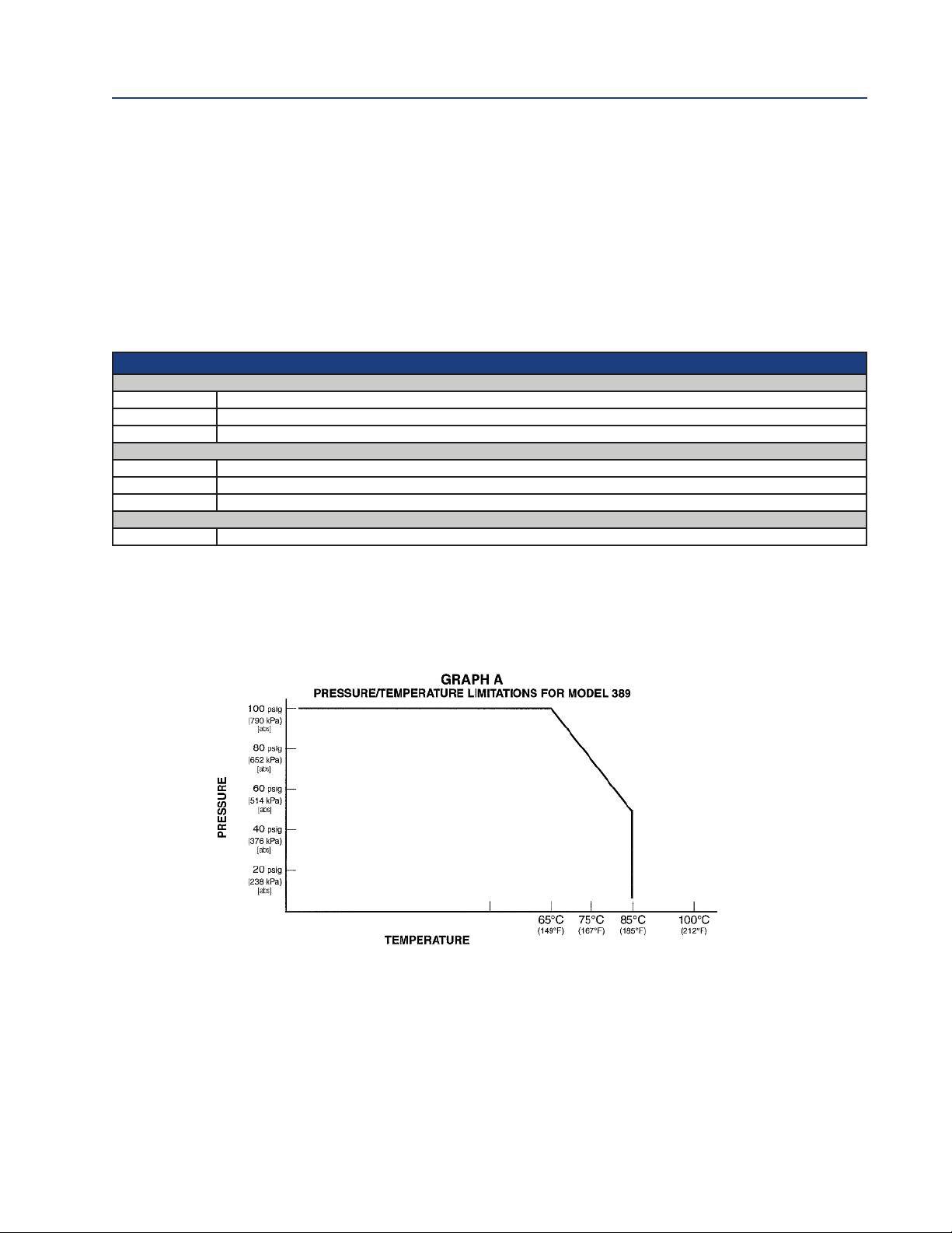
Maximum Pressure:
790 kPa [abs] (100 psig) at 65°C (150°F) - see Graph A
Materials of Construction: Tefzel, glass, ceramic and Viton
Process Connections: 1 in. MNPT, 2 places
Cable: must use mating VP cable, PN 24281-00
Weight/Shipping Weight: 0.45 kg/0.9 kg (1 lb/2 lb)
2 Description and Specifications
Page 9
89VP Instruction Manual Section 1: Description and specifications
3
PN 51-389VP January 2013
1.3
Ordering Information
he 389VP pH/ORP Sensor is offered with a Variopol (VP) connector and uses a mating VP cable
T
(purchased separately). A remote preamplifier (j-box or instrument) must be used with this sensor,
unless (-70) preamplifier option is selected. Model 389VP is SMART enable using option (-70).
A Variopol cable is required for all first-time installations. See below for cable selection. VP8
cable assembly works with VP6 and VP8 sensor connector.
"!
Combination Electrode (Required Selection)
10 General Purpose Low Resistivity, GPLR
11 High pH
12 ORP
Analyzer/TC Compatibility (Required Selection)
50 For use with 1181
54 For use with 1054A/B, 2081; 54, 54e, 81, 1055, 1056, 3081, 4081, 5081, and Xmt, Code 02 only (Pt 100 TC)
55 For use with 1055, 1056, 1057, 1066, 56, 5081, 6081, XMT (-70 option only)
Optional
70 SMART preamplifier (available with -55 only)
FIGURE 1. Pressure/Tempeerature Limitations
Description and Specifications 3
Page 10

ection 1: Description and specifications 389VP Instruction Manual
S
January 2013 PN 51-389VP
This page left blank intentionally
4 Description and Specifications
Page 11

389VP Instruction Manual Section 2: Installation
PN 51-389VP January 2013
Section 2: Installation
2.1
2.2
Unpacking and inspection
Inspect the outside of the carton for any damage. If damage is detected, contact the carrier immediately. Inspect the hardware. Make sure all the items in the packing list are present and in good
condition. Notify the factory if any part is missing. If the instrument appears to be in satisfactory
condition, proceed to Section 2.2, Mounting.
NOTE: Save the original packing cartons and materials as most carriers require proof of damage
due to mishandling, etc. Also, if it is necessary to return the instrument to the factory, you must
pack the instrument in the same manner as it was received. Refer to Section 6 for return instructions. If the sensor is to be stored, the vinyl boot should be filled with pH buffer solution and
replaced on sensor tip until ready for use.
CAUTION
Buffer solution in the vinyl boot may cause skin or eye irritation.
WARNING
Glass electrode must be wetted at all times (in storage and in line) to maximize sensor life.
Mounting
The sensor has been designed to be located in industrial process environments. Temperature and
pressure limitations must not be exceeded at any time. A Caution label regarding this matter is
attached to the sensor with the cable. Please do not remove the label. See Figure 2-1.
CAUTION
Internal electrolyte fill may cause skin or eye irritation
Mounting Guidelines:
1. Shake down the sensor to remove any air bubbles that may be present inside the tip of the pH
glass.
2. Do not install the sensor on the horizontal. The sensor must be 10° off the horizontal to ensure
accuracy.
3. Do not install the sensor upside down.
4. With the standard recessed electrode, air bubbles may become trapped in the sensor end. This
problem is most commonly encountered in areas of low flow or during calibration. Shake the
probe while immersed in solution to remove bubbles.
In most cases, the pH sensor can simply be installed as shipped, and readings with an accuracy of
± 0.2 pH may be obtained. To obtain greater accuracy or to verify proper operation, the sensor
must be calibrated as a loop with its compatible analyzer or transmitter.
Installation 5
Page 12

ection 2: Installation 389VP Instruction Manual
S
January 2013 PN 51-389VP
2.2.1
2.2.2
2.3
Submersion Mounting
The 389 and 389VP Sensor has a 1 in. MNPT process connection at the back of the sensor. Utilizing
a standard 1 in. union, the sensor may be mounted to a 1 in. SCH 80 CPVC or PVDF standpipe.
Tapered pipe threads in plastic tend to loosen after installation. It is therefore recom mended that
Teflon1 tape be used on the threads and that the tightness of the connection be checked frequently to assure that no loosening has occurred. To prevent rain water or condensation from running into the sensor, a weatherproof junction box is recommended (See Figure 2-2). The sensor
cable must be run through a protective conduit for isolation from electrical interference or physical abuse from the process. The sensor should be installed within 80° of vertical, with the electrode
facing down. The sensor’s cable should not be run with power or control wiring.
Flow Through and Insertion Mounting
The 389 and 389VP Sensor also has a 1 in. MNPT process connection at the front of the sensor for
mounting into a 1-1/4 in. tee or the process. See Figure 2-3 for instal lation configurations.
NOTE: LARGE PIPE WRENCHES MUST NOT BE USED TO TIGHTEN THE SENSOR INTO A FLANGE OR
OTHER TYPE OF MOUNTING.
Electrical Installation
Figures 2-5 thru 2-22 provide the guidelines for wiring the 389VP sensor to various
Analyzer/Transmitter instruments.
To determine which wiring guideline to use, locate the code number of the sensor to be installed.
This number is stamped in the body of the sensor.
1. If the cable needs to be extended, use a high quality four conductor shielded instrument cable
available from Rosemount Analytical.
NOTE: If the cable is too long, loop up the excess cable. If the cable has to be shortened, splice and
terminate each conductor neatly and make sure that the overall (outermost) drain wire is not
shorted out with either of the two inner drain wires (shields).
2. Signal cable should be run in a dedicated conduit (preferably an earth grounded metallic conduit) and should be kept away from AC power lines. For your convenience, a spade lug kit is furnished (in a plastic bag wrapped around the cable).
6 Installation
Page 13

89VP Instruction Manual Section 2: Installation
3
PN 51-389VP January 2013
FIGURE 2-1. Dimensional Drawing
WHEN INCH AND METRIC DIMS
ARE GIVEN
MILLIMETER
INCH
Installation 7
Page 14

ection 2: Installation 389VP Instruction Manual
S
January 2013 PN 51-389VP
FIGURE 2-2. Submersion Installations
DWG. NO. REV.
400389VP12 A
WHEN INCH AND METRIC DIMS
ARE GIVEN
MILLIMETER
INCH
DWG. NO. REV.
400389VP11 A
8 Installation
Page 15

89VP Instruction Manual Section 2: Installation
3
PN 51-389VP January 2013
FIGURE 2-3. Flow Through and Insertion Installations
1-1/2” x 1”
Reducing
Bushing
1-1/2” Pipe Tee
Valves and fittings by others. Mount the sensor at least 10° from horizontal.
FIGURE 2-4. VP8 Cable, sensor end
1-1/2” x 1”
Reducing
Bushing
1-1/2” Pipe Tee
1-1/2” x 1”
Reducing
Bushing
#$
1-1/2” Pipe “Y”
FIGURE 2-5. VP8 Cable, instrument end
Installation 9
Page 16

ection 2: Installation 389VP Instruction Manual
S
January 2013 PN 51-389VP
IGURE 2-6. VP6 81 Wiring
F
FIGURE 2-8. VP6 54 Wiring through Remote Junction Box
IGURE 2-7. VP6 1181 Wiring
F
FIGURE 2-9. VP6 54 Wiring FIGURE 2-10. VP6 2081 Wiring
10 Installation
Page 17

89VP Instruction Manual Section 2: Installation
3
PN 51-389VP January 2013
IGURE 2-11. VP6 1181, 1050/1060, and 1003/1023
F
Wiring through Remote Junction Box
IGURE 2-12. VP6 2081 Wiring through Remote
F
Junction Box
FIGURE 2-13. VP6 1055-22-32 Wiring FIGURE 2-14. VP6 3081
& 4081 Wiring
Installation 11
Page 18

ection 2: Installation 389VP Instruction Manual
S
January 2013 PN 51-389VP
IGURE 2-15. VP6 81 Wiring through Remote
F
Junction Box
IGURE 2-16. VP6 3081 & 4081 Wiring through
F
Remote Junction Box
FIGURE 2-17. VP6 1054 Wiring FIGURE 2-18. VP6 1054A/B and 2054 Wiring
12 Installation
Page 19

89VP Instruction Manual Section 2: Installation
3
PN 51-389VP January 2013
IGURE 2-19. CAS Installation, label information
F
FIGURE 2-20. 1054A/B & 2054 VP6 Wiring through
a Remote Junction Box
FIGURE 2-21. 1055-22-32 VP6 Wiring through Remote Junction Boxes
Installation 13
Page 20

ection 2: Installation 389VP Instruction Manual
S
January 2013 PN 51-389VP
IGURE 2-22. SCL-(P/Q) Wiring
F
IGURE 2-23. 2700 Wiring
F
FIGURE 2-23. 54e pH/ORP Wiring. This is the standard VP8 cable wiring. VP8 cable assembly works both
with VP6 and VP8 sensor connector
14 Installation
Page 21

89VP Instruction Manual Section 2: Installation
3
PN 51-389VP January 2013
IGURE 2-25. Xmt VP8 Wiring. This is the standard VP8 cable wiring. VP8 cable assembly works both with
F
VP6 and VP8 sensor connector
FIGURE 2-26. 1056 VP8 Wiring. This is the standard VP8 cable wiring. VP8 cable assembly works both with
VP6 and VP8 sensor connector
Installation 15
Page 22

ection 2: Installation 389VP Instruction Manual
S
January 2013 PN 51-389VP
IGURE 2-27. 5081 VP8 Wiring. This is the standard VP8 cable wiring. VP8 cable assembly works both with
F
VP6 and VP8 sensor connector
16 Installation
Page 23

89VP Instruction Manual Section 3: Start-up and Calibration
3
PN 51-389VP January 2013
Section 3: Start-up and Calibration
3.1
3.2
3.2.1
Sensor Preparation
Shake down the sensor to remove any air bubbles that may be present at the tip of the pH glass
bulb. In most cases, the pH sensor can simply be installed as shipped and readings with an accuracy of ± 0.2 pH may be obtained. To obtain greater accuracy or to verify proper operation, the sensor must be calibrated as a loop with its compatible analyzer or transmitter.
389VP pH Calibration
1. After a temporary connection is established between the sensor and the instrument, a buffer
calibration may be performed.
2. Consult appropriate pH/ORP analyzer or transmitter instruction manual for specific calibration
and standardization procedures, or see below for recommended two point buffer calibration
procedure.
Recommended two point buffer calibration procedure
Select two stable buffer solutions, preferably pH 4.0 and 10.0 (pH buffers other than pH 4.0 and
pH 10.0 can be used as long as the pH values are at least two pH units apart).
NOTE: A pH 7 buffer solution reads a mV value of approx. zero, and pH buffers read approx. +/-
59.1 mV for each pH unit above or below pH 7. Check the pH buffer manufacturer specifications
for millivolt values at various temperatures since it may affect the actual value of the buffer solution mV/pH value.
1. Immerse sensor in the first buffer solution. Allow sensor to adjust to the buffer temperature
(to avoid errors due to temperature differences between the buffer solution and sensor temperature) and wait for reading to stabilize. The value of buffer can now be acknowledged by
analyzer/transmitter.
2. Once the first buffer has been acknowledged by the analyzer/transmitter, rinse the buffer solution off of the sensor with distilled or deionized water.
3. Repeat steps 1 and 2 using the second buffer solution.
4. Once the analyzer/transmitter has acknowledged both buffer solutions, a sensor slope
(mV/pH) is established (the slope value can be found within the analyzer/transmitter).
5. The slope value should read about 59.1 mV/pH for a new sensor and will decrease over time
to approximately 47 - 49 mV/pH. Once the slope reads below the 47-49 mV/pH range, a new
sensor should be installed to maintain accurate readings.
3.2.2
Start-up and Calibration 17
Recommended pH Sensor Standardization
For maximum accuracy, the sensor can be standardized on-line or with a process grab sample after
a buffer calibration has been performed and the sensor has been conditioned to the process.
Standardization accounts for the sensor junction potential and other interferences.
Standardization will not change the sensor’s slope but will simply adjust the analyzers reading to
match that of the known process pH.
1. While obtaining a process solution sample (it is recommended that the sample is taken close
to the sensor), record the pH value that is shown on the analyzer/transmitter display.
Page 24

ection 3: Start-up and Calibration 389VP Instruction Manual
S
January 2013 PN 51-389VP
. Measure and record the pH of the process solution sample with a another temperature com-
2
pensated, calibrated pH instrument. For best results, standardization should be performed at
he process temperature.
t
3. Adjust the analyzer/transmitter value to the standardized value.
3.3
3.3.1
389VP ORP
Most industrial applications have a number of ORP reactions occurring in sequence or simultaneously. There can be several components that are oxidized or reduced by the reagents that are used.
Theoretically, the ORP potential is absolute because it is the result of the oxidationreduction equilibrium. However, the actual measured potential is dependent on many factors, including the condition of the surface of the ORP platinum electrode. Therefore, the sensor should be allowed 1-2
hours to become “conditioned” to the stream when first set-up or after being cleaned.
Calibration
CAUTION
The solution used during the following check is an acid and should be handled with care. Follow the
directions of the acid manufacturer. Wear the proper protective equipment. Do not let the solution
come in contact with skin or clothing. If contact with skin is made, immediately rinse with clean water.
1. Make a temporary electrical connection between the sensor and the instrument.
2. Obtain a standard solution of saturated quinhydrone (PN R508-160Z). This can be made quite
simply by adding a few crystals of quinhydrone to either pH 4 or pH 7 buffer. Quinhydrone is
only slightly soluble, but only a few crystals will be required (refer to Section 4.3.1 for an alternate ORP standard solution).
3. Immerse the sensor in the standard solution. Allow 1-2 minutes for the ORP sensor to stabilize.
4. Adjust the standardize control of the transmitter to the solution value shown in Table 3-1. The
resulting potentials, measured with a clean platinum electrode and saturated KCl/AgCl reference electrode, should be within ±20 millivolts of the value shown in Table 3-1. Solution temperature must be noted to ensure accurate interpretation of results. The ORP value of saturated quinhydrone solution is not stable over long periods of time. Therefore, these standards
should be made up fresh each time they are used.
TABLE 3-1. ORP of Saturated Quinhydrone Solution (millivolts)
pH 4 Solution pH 7 Solution
Temp °C 20 25 30 20 25 30
mV Potential 268 264 260 94 87 80
5. Remove the sensor from the buffer, rinse, and install in the process.
18 Start-up and Calibration
Page 25

89VP Instruction Manual Section 4: Maintenance
3
PN 51-389VP January 2013
Section 4: Maintenance
The 389VP Sensor requires minimum maintenance. The sensor should be kept clean and free of
debris and sediment at all times. The frequency of cleaning by wiping or brushing with a soft cloth
or brush is determined by the nature of the solution being measured. The sensor should be
removed from the process periodically and checked in buffer solutions.
WARNING
BEFORE REMOVING THE SENSOR, be absolutely certain that the process pressure is reduced to 0 psig
and the process temperature is lowered to a safe level!
If the sensor will not calibrate, refer to your analyzer/transmitter instruction manual for proper test
procedures. If it is determined that the sensor has failed, it should be discarded and replaced.
4.1
4.2
Electrode Cleaning
If the electrode is coated or dirty, clean as follows:
1. Remove the sensor from process.
2. Wipe the glass bulb with a soft, clean, lint free cloth or tissue. If this does not remove the dirt
or coating, go to Step 3 (detergents clean oil and grease; acids remove scale.)
3. Wash the glass bulb in a strong detergent solution, and rinse it in clean water. If this does not
clean the glass bulb, go to Step 4.
CAUTION
The solution used during the following check is an acid and should be handled with care. Follow the
directions of the acid manufacturer. Wear the proper protective equipment. Do not let the solution
come in contact with skin or clothing. If contact with skin is made, immediately rinse with clean water.
4. Wash the glass bulb in a dilute 5% hydro chloric acid solution, and rinse with clean water.
Soaking the sensor overnight in the acid solution can improve cleaning action.
Replace the sensor if it cannot be cleaned.
Automatic Temperature Compensator
The temperature compensator element is a temperature sensitive resistor and can be checked
with an ohmmeter. Resistance increases with temperature.
The 3K element will read 3000 ohms ± 1% at 25°C (77°F), and a Pt100 will read 110 ohms.
Resistance varies with temperature for a 3K and Pt-100 element and can be determined according
to Table 4-2 or the following formula:
= RO[1 + R1(T-20)]
R
T
Where R
T = Temperature in °C
Refer to Table 4-1 for R
= Resistance
t
and R1values.
O
Maintenance 19
Page 26

ection 4: Maintenance 389VP Instruction Manual
S
January 2013 PN 51-389VP
TABLE 4-1. ROand R1values for temperature compensation elements
Temperature R
Compensation Element
3K 2934 .0045
PT-100 107.7 .00385
TABLE 4-2. Temperature vs. Resistance of auto T.C. elements
Resistance
Temperature °C (Ohms) ±1%
3K PT-100
0 2670 100.0
10 2802 103.8
20 2934 107.7
25 3000 109.6
30 3066 111.5
40 3198 115.4
50 3330 119.2
60 3462 123.1
70 3594 126.9
80 3726 130.8
90 3858 134.6
100 3990 138.5
O
R
1
4.3
4.3.1
389VP ORP
Platinum Electrode Check
The platinum electrode may be checked as follows. There are two types of standard solutions
which may be used to check the ORP electrode/transmitter system:
Type 1: One type of commonly used ORP standard solution is the saturated quinhydrone solution
(PN R508-160Z). Refer to Section 3.3.
CAUTION
The solution used during the following check is an acid and should be handled with care. Follow the
directions of the acid manufacturer. Wear the proper protective equipment. If contact with skin of
clothing is made, immediately rinse with plenty of clean water.
Type 2: A second ORP standard solution can be prepared from the following recipe: Dissolve 39.2
grams of reagent grade ferrous ammonium sulfate, Fe(NH
reagent grade ferric ammonium sulfate, FeNH4(SO4)2• 12H2O, in approximately 700 milliliters of
water (distilled water is preferred, but tap water is acceptable). Slowly and carefully add 56.2 milliliters of concentrated sulfuric acid. Add sufficient water to bring the total solution volume up to
1000 ml. This standard ORP solution, although not as simple to prepare as the quinhydrone recipe,
is much more stable, and will maintain its millivolt value for approximately one year when stored
in glass containers. This solution (ferric/ferrous ammonium sulfate) will produce a nominal ORP of
(SO4)2• 6H2O and 48.2 grams of
4)2
20 Maintenance
Page 27

89VP Instruction Manual Section 4: Maintenance
3
PN 51-389VP January 2013
476 +20 mV at 25°C when used with a saturated KCl/AgCl reference electrode and platinum meas-
ring electrode. Some tolerance in mV values is to be expected due to the rather large liquid ref-
u
erence junction potentials that can arise when measuring this strongly acidic and concentrated
solution. However, if the measuring electrodes are kept clean and in good operating condition,
consistently repeatable calibrations can be carried out using this standard solution.
4.3.2
Cleaning Platinum Electrode
The electrode can be restored to normal operation by simply cleaning the platinum electrode with
baking soda. Polish it by rubbing it with a damp paper towel and baking soda until a bright, shiny
appearance is attained.
Maintenance 21
Page 28

ection 4: Maintenance 389VP Instruction Manual
S
January 2013 PN 51-389VP
This page left blank intentionally
22 Maintenance
Page 29

89VP Instruction Manual Section 5: Troubleshooting
ydemeResuaC elbaborPelbuorT
Meter reads off scale (Display Defective preamplifier. Replace preamplifier (for code 02
reads overrange).
sensors). For code 01, replace sensor.
T.C. element shorted. Check T.C. element as instructed
in Section 4.2 and
replace sensor if defective.
Make sure sensor is in process with
ot refer( maerts elpmas tneiciffus
Section 2.0 for installation details).
Open glass electrode. Replace sensor.
Reference element open - no contact.
Replace sensor.
Display reads between 3 and 6 pH Electrode cracked. Replace sensor.
regardless of actual pH of solution
or sample.
Meter or display indication swings T.C. element shorted Check T.C. element as instructed
ecalper dna 2.4 noitceS ni.edoM .C.T OTUA ni ylediw spmuj ro
sensor if defective.
Span between buffers extremely
Check T.C. element as instructed
in Section 4.2 and replace
sensor if defective.
.edoM .C.T OTUA ni trohs
Sluggish or slow meter indication
.level Hp ni segnahc laer rof
Electrode defective.
Transmitter cannot be standardized.
Defective preamplifier. Replace preamplifier.
T.C. element shorted
Electrode cracked. Clean sensor as instructed in
Sections 4.1 or 4.3.2. Replace
sensor if cracked.
Electrode coated or cracked. Clean Sensor as instructed in
Sections 4.1 or 4.3.2 and, if
cracked, replace sensor.
Replace sensor.
Transmitter short spans between
two different buffer values.
Old glass electrode or high
temperature exposure.
Replace sensor.
Coated glass. Clean Sensor as instructed in
Sections 4.1 or 4.3.2. Replace
sensor if cracked.
Sensor not in process or sample
stream is low.
3
PN 51-389VP January 2013
Section 5: Troubleshooting
TABLE 5-1. Troubleshooting
Troubleshooting 23
Page 30

ection 5: Troubleshooting 389VP Instruction Manual
S
January 2013 PN 51-389VP
PART DESCRIPTION
24281-00 15 ft. VP8 cable
24281-01 25 ft. VP8 cable
24281-02 2.5 ft. VP8 cable
24281-03 50 ft. VP8 cable
24281-04 100 ft. VP8 cable
24281-05 4 ft. VP8 cable
24281-06 10 ft. VP8 cable
24281-07 20 ft. VP8 cable
24281-08 30 ft. VP8 cable
23645-06 15 ft. cable with mating VP6 connector, prepped with BNC on instrument end
23645-07 15 ft. cable with mating VP6 connector, prepped without BNC on instrument end
24 Troubleshooting
Page 31

89VP Instruction Manual Section 6: Return of Material
3
PN 51-389VP January 2013
Section 6: Return of Material
6.1 General
To expedite the repair and return of instruments, proper communication between the customer
and the factory is important. A return material authorization number is required. Call 1-800-6547768 or (949) 757-8500. The “Return of Materials Request” form is provided for you to copy and
use in case the situation arises. The accuracy and completeness of this form will affect the processing time of your materials.
6.2 Warranty Repair
The following is the procedure for returning products still under warranty.
1. Contact the factory for authorization.
2. Complete a copy of the “Return of Materials Request” form as completely and accurately as
possible.
3. To verify warranty, supply the factory sales order number or the original purchase order
number. In the case of individual parts or sub-assemblies, the serial number on the unit must
be supplied.
4. Carefully package the materials and enclose your “Letter of Transmittal” and the completed
copy of the “Return of Materials Request” form. If possible, pack the materials in the same
manner as it was received.
IMPORTANT
Please see second section of “Return of Materials Request Form”. Compliance to the OSHA requirements is mandatory for the safety of all personnel. MSDS forms and a certification that the instruments have been disinfected or detoxified are required.
5. Send the package prepaid to:
Rosemount Analytical Inc.
2400 Barranca Parkway
Irvine, CA 92606
Attn: Factory Repair
Mark the package: Returned for Repair RMA No. __________
6.3 Non-Warranty Repair
1. Contact the factory for authorization.
2. Fill out a copy of the “Return of Materials Request” form as completely and accurately as possible.
3. Include a purchase order number and make sure to include the name and telephone number
of the right individual to be contacted should additional information be needed.
4. Do Steps 4 and 5 of Section 6.2.
NOTE
Model No. __________
Consult the factory for additional infor mation regarding service or repair.
Return of Material 25
Page 32

ection 6: Return of Material 389VP Instruction Manual
S
January 2013 PN 51-389VP
RETURN OF MATERIALS REQUEST
RETURNED BY: BILL TO:
•IMPORTANT!
This form must be completed to ensure expedient factory service.
_____________________________ _____________________________ ____________________________
_____________________________ _____________________________ ____________________________
_____________________________ _____________________________ ____________________________
NOTICE TO SENDER: CUSTOMER/USER MUST SUBMIT MATERIAL SAFETY SHEET (MSDS) or complete stream composition, and/or letter certifying the materials have been disinfected and/or detoxified when returning any product, sample or material that have been
exposed to or used in an environment or process that contains a hazardous material any of the above that is submitted to rosemount
analytical without the msds will be returned to sender c.o.d. fo9r the safety and health of our employees. we thank you in advance for
compliance to this subject.
SENSOR OR CIRCUIT BOARD ONLY:
(Please reference where from in MODEL / SER. NO. Column)
1. PART NO. ______________________ 1. MODEL ______________________ 1. SER. NO. ___________________
2. PART NO. ______________________ 2. MODEL ______________________ 2. SER. NO. ___________________
3. PART NO. ______________________ 3. MODEL ______________________ 3. SER. NO. ___________________
4. PART NO. ______________________ 4. MODEL ______________________ 4. SER. NO. ___________________
REASON FOR RETURN
PLEASE CHECK ONE:
n
REPAIR AND CALIBRATE
n
EVALUATION
n
REPLACEMENT REQUIRED?nYESnNO _______________________________________________________
DESCRIPTION OF MALFUNCTION:
n
DEMO EQUIPMENT NO. ______________________________________
n
OTHER (EXPLAIN) __________________________________________
________________________________________________________________________________________________
________________________________________________________________________________________________
________________________________________________________________________________________________
WARRANTY REPAIR REQUESTED:
n
YES. REFERENCE ORIGINAL ROSEMOUNT ANALYTICAL ORDER NO. ______________________________________________
CUSTOMER PURCHASE ORDER NO. ______________________________________________
n
NO. PROCEED WITH REPAIRS-INVOICE AGAINST P.O. NO. _____________________________________________________
n
NO. CONTACT WITH ESTIMATE OF REPAIR CHARGES: BY LETTER
NAME _________________________________________________________________ PHONE ____________________
ADDRESS _________________________________________________________________________________________
______________________________________________________________________
RETURN AUTHORITY FOR CREDIT ADJUSTMENT [Please check appropriate box(s)]
n
WRONG PART RECEIVED
n
DUPLICATE SHIPMENT REFERENCE ROSEMOUNT ANALYTICAL SALES ORDER NO. ____________________
n
RETURN FOR CREDIT RETURN AUTHORIZED BY: __________________________________________
WARRANTY DEFECT _________________________________________________________________________________
24-6047
n
REPLACEMENT RECEIVED
n
OR BY PHONE
n
ZIP ______________________
26 Return of Material
Page 33

89VP Instruction Manual Warranty
3
PN 51-389VP January 2013
WARRANTY
Seller warrants that the firmware will execute the programming instructions provided by Seller, and that the Goods
manufactured or Services provided by Seller will be free from defects in materials or workmanship under normal use and
care until the expiration of the applicable warranty period. Goods are warranted for twelve (12) months from the date
of initial installation or eighteen (18) months from the date of shipment by Seller, whichever period expires first.
onsumables, such as glass electrodes, membranes, liquid junctions, electrolyte, o-rings, catalytic beads, etc.,
C
and Services are warranted for a period of 90 days from the date of shipment or provision.
Products purchased by Seller from a third party for resale to Buyer ("Resale Products") shall carry only the warranty
extended by the original manufacturer. Buyer agrees that Seller has no liability for Resale Products beyond making a reasonable commercial effort to arrange for procurement and shipping of the Resale Products.
If Buyer discovers any warranty defects and notifies Seller thereof in writing during the applicable warranty period, Seller
shall, at its option, promptly correct any errors that are found by Seller in the firmware or Services, or repair or replace
F.O.B. point of manufacture that portion of the Goods or firmware found by Seller to be defective, or refund the purchase price of the defective portion of the Goods/Services.
All replacements or repairs necessitated by inadequate maintenance, normal wear and usage, unsuitable power sources,
unsuitable environmental conditions, accident, misuse, improper installation, modification, repair, storage or handling,
or any other cause not the fault of Seller are not covered by this limited warranty, and shall be at Buyer's expense. Seller
shall not be obligated to pay any costs or charges incurred by Buyer or any other party except as may be agreed upon in
writing in advance by an authorized Seller representative. All costs of dismantling, reinstallation and freight and the time
and expenses of Seller's personnel for site travel and diagnosis under this warranty clause shall be borne by Buyer unless
accepted in writing by Seller.
Goods repaired and parts replaced during the warranty period shall be in warranty for the remainder of the original warranty period or ninety (90) days, whichever is longer. This limited warranty is the only warranty made by Seller and can
be amended only in a writing signed by an authorized representative of Seller. Except as otherwise expressly provided in
the Agreement, THERE ARE NO REPRESENTATIONS OR WARRANTIES OF ANY KIND, EXPRESS OR IMPLIED, AS TO MERCHANTABILITY, FITNESS FOR PARTICULAR PURPOSE, OR ANY OTHER MATTER WITH RESPECT TO ANY OF THE GOODS
OR SERVICES.
RETURN OF MATERIAL
Material returned for repair, whether in or out of warranty, should be shipped prepaid to:
Emerson Process Management
Liquid Division
2400 Barranca Parkway
Irvine, CA 92606
The shipping container should be marked:
RETURN FOR REPAIR
Model _______________________________
The returned material should be accompanied by a letter of transmittal which should include the following information
(make a copy of the "Return of Materials Request" found on the last page of the Manual and provide the following thereon):
1. Location type of service, and length of time of service of the device.
2. Description of the faulty operation of the device and the circumstances of the failure.
3. Name and telephone number of the person to contact if there are questions about the returned material.
4. Statement as to whether warranty or non-warranty service is requested.
5. Complete shipping instructions for return of the material.
Adherence to these procedures will expedite handling of the returned material and will prevent unnecessary additional
charges for inspection and testing to determine the problem with the device.
If the material is returned for out-of-warranty repairs, a purchase order for repairs should be enclosed.
Warranty 27
Page 34

8
89VP Instruction Manual
3
January 2013 PN 51-389VP
facebook.com/EmersonRosemountAnalytical
AnalyticExpert.com
twitter.com/RAIhome
youtube.com/user/RosemountAnalytical
Emerson Process Management
2400 Barranca Parkway
Irvine, CA 92606 USA
Tel: (949) 757-8500
Fax: (949) 474-7250
rosemountanalytical.com
© Rosemount Analytical Inc. 2013
Credit Cards for U.S. Purchases Only.
©2013 Rosemount Analytical, Inc. All rights reserved.
The Emerson logo is a trademark and service mark of Emerson Electric Co. Brand name is a mark
of one of the Emerson Process Management family of companies. All other marks are the property
of their respective owners.
The contents of this publication are presented for information purposes only, and while effort has
been made to ensure their accuracy, they are not to be construed as warranties or guarantees,
express or implied, regarding the products or services described herein or their use or applicability.
All sales are governed by our terms and conditions, which are available on request. We reserve the
right to modify or improve the designs or specifications of our products at any time without notice.
 Loading...