

Page 1
Instruction Manual
748332-F
April 2003
Model NGA2000 NDIR
Non-Dispersive Infrared Analyzer
http://www.processanalytic.com
Page 2

ESSENTIAL INSTRUCTIONS
READ THIS PAGE BEFORE PROCEEDING!
Rosemount Analytical designs, manufactures and tests its products to meet many national and
international standards. Because these instruments are sophisticated technical products, you MUST
properly install, use, and maintain them to ensure they continue to operate within their normal
specifications. The following instructions MUST be adhered to and integrated into your safety program
when installing, using, and maintaining Rosemount Analytical products. Failure to follow the proper
instructions may cause any one of the following situations to occur: Loss of life; personal injury; property
damage; damage to this instrument; and warranty invalidation.
• Read all instructions
prior to installing, operating, and servicing the product.
• If you do not understand any of the instructions, contact your Rosemount Analytical
representative for clarification.
• Follow all warnings, cautions, and instructions
marked on and supplied with the product.
• Inform and educate your personnel in the proper installation, operation, and maintenance of
the product.
• Install your equipment as specified in the Installation Instructions of the appropriate
Instruction Manual and per applicable local and national codes. Connect all products to the
proper electrical and pressure sources.
• To ensure proper performance, use qualified personnel
to install, operate, update, program, and
maintain the product.
• When replacement parts are required, ensure that qualified people use replacement parts specified
by Rosemount. Unauthorized parts and procedures can affect the product’s performance, place the
safe operation of your process at risk, and VOID YOUR WARRANTY
. Look-alike substitutions may
result in fire, electrical hazards, or improper operation.
• Ensure that all equipment doors are closed and protective covers are in place, except when
maintenance is being performed by qualified persons, to prevent electrical shock and
personal injury.
The information contained in this document is subject to change without notice.
®
Pyrex
Irtran
Teflon
Ty-Rap
is a registered trademark of Corning Glass Works
®
is a registered trademark of Eastman Kodak Co.
®
and Viton® is a registered trademark of E.I. duPont de Nemours and Co., Inc.
®
is a registered trademark of Thomas & Betts Corp.
Emerson Process Management
Rosemount Analytical Inc.
Process Analytic Division
1201 N. Main St.
Orrville, OH 44667-0901
T (330) 682-9010
F (330) 684-4434
e-mail: gas.csc@EmersonProcess.com
http://www.processanalytic.com
Page 3

Model NGA2000 NDIR
TABLE OF CONTENTS
Instruction Manual
748332-F
April 2003
PREFACE...........................................................................................................................................P-1
Definitions...........................................................................................................................................P-1
Safety Summary.................................................................................................................................P-2
General Precautions For Handling And Storing High Pressure Gas Cylinders .................................P-4
Documentation....................................................................................................................................P-5
Compliances.......................................................................................................................................P-5
Glossary Of Terms ...........................................................................................................................P-6
1-0 DESCRIPTION AND SPECIFICATIONS .................................................................................................1-1
1-1 Overview................................................................................................................................1-1
1-2 Typical Applications...............................................................................................................1-1
1-3 Theory Of Technology...........................................................................................................1-1
1-4 Sample Requirements...........................................................................................................1-3
1-5 Purge Kits..............................................................................................................................1-3
1-6 Features.................................................................................................................................1-3
1-7 Specifications.........................................................................................................................1-5
a. General ...........................................................................................................................1-5
b. Physical...........................................................................................................................1-5
c. Sample......................................................................................................................... ...1-5
2-0 INSTALLATION........................................................................................................................................2-1
2-1 Unpacking..............................................................................................................................2-1
2-2 Assembly...............................................................................................................................2-1
2-3 Location.................................................................................................................................2-2
2-4 Gas Specifications.................................................................................................................2-2
a. Calibration Gases............................................................................................................2-2
b. Flow Rate........................................................................................................................2-2
c. Sample Pressure/Filtration..............................................................................................2-2
d. Leak Test ........................................................................................................................2-2
2-5 Gas Connections...................................................................................................................2-2
2-6 Electrical Connections...........................................................................................................2-4
3-0 STARTUP AND OPERATION..................................................................................................................3-1
3-1 Overview................................................................................................................................3-1
3-2 Display Screens.....................................................................................................................3-1
a. Run Mode Display...........................................................................................................3-1
b. Menu Displays.................................................................................................................3-1
c. Help Displays ..................................................................................................................3-1
3-3 Startup Procedure .................................................................................................................3-1
3-4 Binding...................................................................................................................................3-2
3-5 Calibration..............................................................................................................................3-4
3-6 Linearization ..........................................................................................................................3-6
3-7 Routine Operation .................................................................................................................3-8
Rosemount Analytical Inc. A Division of Emerson Process Management Contents i
Page 4

Instruction Manual
748332-F
April 2003
4-0 MAINTENANCE AND TROUBLESHOOTING.........................................................................................4-1
4-1 Overview................................................................................................................................4-1
4-2 PCB Replacement.................................................................................................................4-1
4-3 Power Fuse Replacement.....................................................................................................4-2
4-4 Module Fan Replacement .....................................................................................................4-3
4-5 Chopper Motor Replacement ................................................................................................4-4
4-6 Source Replacement.............................................................................................................4-4
4-7 Detector Removal..................................................................................................................4-5
4-8 Flow Sensor Replacement ....................................................................................................4-6
4-9 Case Temperature Sensor Replacement..............................................................................4-6
4-10 Thermal Fuse Replacement..................................................................................................4-6
4-11 Oscillator Tune/Source Balance Shutter Adjustment............................................................4-6
4-12 Cleaning Cells........................................................................................................................4-8
4-13 Cell Desiccant........................................................................................................................4-10
4-14 Modulation Check..................................................................................................................4-11
5-0 REPLACEMENT PARTS..........................................................................................................................5-1
5-1 Matrix.....................................................................................................................................5-1
5-2 Replacement Parts................................................................................................................5-2
Model NGA2000 NDIR
6-0 RETURN OF MATERIAL..........................................................................................................................6-1
6-1 Return Of Material.................................................................................................................6-1
6-2 Customer Service..................................................................................................................6-1
6-3 Training..................................................................................................................................6-1
7-0 APPENDIX A. MENU DISPLAYS ...........................................................................................................7-1
8-0 INDEX 8-1
ii Contents Rosemount Analytical Inc. A Division of Emerson Process Management
Page 5

Model NGA2000 NDIR
LIST OF ILLUSTRATIONS
Figure 1-1. NDIR Technology .................................................................................................. 1-2
Figure 1-2. NGA2000 NDIR Analyzer Module (Typical - Actual Configuration May Vary)...... 1-4
Figure 2-1. Analyzer Module Installation into Instrument Platform .......................................... 2-1
Figure 2-2. NDIR Back Panel...................................................................................................2-3
Figure 2-3. NDIR Front Panel Electrical Connections.............................................................. 2-4
Figure 2-4. NDIR Wiring Diagram............................................................................................ 2-5
Figure 2-5. Outline and Mounting Dimensions......................................................................... 2-6
Figure 3-1. Run Mode Display ................................................................................................. 3-2
Figure 3-2. Main Menu Display ................................................................................................3-2
Figure 3-3. Basic Controls Menu.............................................................................................. 3-3
Figure 3-4. Expert Controls and Setup Menu........................................................................... 3-3
Figure 3-5. Technical Level Configuration Menu.....................................................................3-3
Figure 3-6. Typical Help Screen............................................................................................... 3-4
Figure 3-7. Typical Linearization Curve, Linearizer OFF......................................................... 3-7
Figure 3-8. Operator-Determined Linearization Curve (Normalized).......................................3-7
Figure 3-9. Display Screens (1 of 5) ........................................................................................ 3-9
Figure 3-10. Display Screens (2 of 5)......................................................................................3-10
Figure 3-11. Display Screens (3 of 5)......................................................................................3-11
Figure 3-12. Display Screens (4 of 5)......................................................................................3-12
Figure 3-13. Display Screens (5 of 5)......................................................................................3-13
Figure 4-1. Printed Circuit Board Fold-Out Panel Views.......................................................... 4-2
Figure 4-2. Power Fuse Location............................................................................................. 4-2
Figure 4-3. Fan Assembly........................................................................................................ 4-3
Figure 4-4. Motor/Source Assembly......................................................................................... 4-4
Figure 4-5. Cell, PCB Assembly – Exploded View................................................................... 4-5
Figure 4-6. Oscillator Tune, Source Balance Shutter Adjustments ......................................... 4-7
Figure 4-7. Detector Block (Exploded View)............................................................................ 4-7
Figure 4-8. Cell Assembly........................................................................................................ 4-9
Instruction Manual
748332-F
April 2003
LIST OF TABLES
Table 2-1. Cell Purging Times at Atmospheric Sample Pressure .......................................... 2-3
Table 3-1. NDIR Analyzer Module Alarms.............................................................................. 3-5
Table 4-1. Cell Desiccant...................................................................................................... 4-10
Rosemount Analytical Inc. A Division of Emerson Process Management Contents iii
Page 6

Instruction Manual
748332-F
April 2003
Model NGA2000 NDIR
iv Contents Rosemount Analytical Inc. A Division of Emerson Process Management
Page 7
Instruction Manual
Model NGA2000 NDIR
PREFACE
The purpose of this manual is to provide information concerning the components, functions,
installation and maintenance of the NGA2000 NDIR and the System Accessories of the NGA2000
System.
Some sections may describe equipment not used in your configuration. The user should become
thoroughly familiar with the operation of this module before operating it. Read this instruction
manual completely.
DEFINITIONS
The following definitions apply to DANGERS, WARNINGS, CAUTIO NS and NOTES found throughout
this publication.
748332-F
April 2003
DANGER .
Highlights the presence of a hazard which will cause severe personal injury, death, or substantial
property damage if the warning is ignored.
WARNING .
Highlights an operation or maintenance procedure, practice, condition, statement, etc. If not
strictly observed, could result in injury, death, or long-term health hazards of personnel.
CAUTION
Highlights an operation or maintenance procedure, practice, condition, statement, etc. If not
strictly observed, could result in damage to or destruction of equipment, or loss of effectiveness.
NOTE
Highlights an essential operating procedure,
condition or statement.
Rosemount Analytical Inc. A Division of Emerson Process Management Preface P-1
Page 8
Instruction Manual
748332-F
April 2003
Model NGA2000 NDIR
SAFETY SUMMARY
If this equipment is used in a manner not specified in these instructions, protective systems may be
impaired.
AUTHORIZED PERSONNEL
To avoid explosion, loss of life, personal injury and damage to this equipment and on-site property,
all personnel authorized to install, operate and service the this equipment should be thoroughly
familiar with and strictly follow the instructions in this manual. SAVE THESE INSTRUCTIONS.
DANGER.
ELECTRICAL SHOCK HAZARD
Do not operate without doors and covers secure. Servicing requires access to live parts which can
cause death or serious injury. Refer servicing to qualified personnel. For safety and proper
performance this instrument must be connected to a properly grounded three-wire source of power.
WARNING .
POSSIBLE EXPLOSION HAZARD
This equipment is not designed for and should not be used in the analysis of flammable samples.
Use of this equipment in this way could result in explosion and death.
Ensure that all gas connectors are made as labeled and are leak free. Improper gas connections
could result in explosion or death.
WARNING.
OVER-VOLTAGE SPIKING
If this Analyzer Module is used with a non-Rosemount Analytical po wer supply, adding Rosemo unt
Analytical PN 903341 Current Protector in series with the 24V positive power line will prevent overvoltage spiking and resultant fuse blowing when powering up the instrument.
CAUTION
PRESSURIZED GAS
This module requires periodic calibration with a known standard gas. See General Precautions for
Handling and Storing High Pressure Gas Cylinders on page P-4.
P-2 Preface Rosemount Analytical Inc. A Division of Emerson Process Management
Page 9
Instruction Manual
Model NGA2000 NDIR
CAUTION
HAND INJURY HAZARD
Dropping the front panel of the Platform while hand or fingers are inside either case handle can
cause serious injury.
CAUTION
PARTS INTEGRITY
Tampering with or unauthorized substitution of components may adversely affect safety of this
product. Use only factory approved components for repair.
CAUTION
OVERBALANCE HAZARD
This Analyzer Module may tip instrument over if it is pulled out too far and the Platform is not
properly supported.
748332-F
April 2003
CAUTION
POSSIBLE CELL DAMAGE
Apply leak test liquid to cell or detectors only as a last resort.
NOTICE
Software compatibility is necessary for all NGA2000 components in your system to work together.
The version of your Platform's software must be equal to or greater that the version of any other
module(s) for successful compatibility. If it is not, contact Rosemount Analytical at 800-433-6076 to
order software upgrade kit PN 657150 for the Platform.
You can locate the version of each NGA2000 component as follows:
Platform Controller Board
Turn power ON. The display will show "Control Module V2. ...". This is the software version.
Analyzer Module
Located on the right side of the Analyzer Module case.
I/O Module
Located on the backplane connector of the module. If no label is present, the module is Version
2.0.
Rosemount Analytical Inc. A Division of Emerson Process Management Preface P-3
Page 10

Instruction Manual
748332-F
April 2003
Model NGA2000 NDIR
GENERAL PRECAUTIONS FOR HANDLING AND STORING HIGH
PRESSURE GAS CYLINDERS
Edited from selected paragraphs of the Compressed Gas Association's "Handbook of Compressed
Gases" published in 1981
Compressed Gas Association
1235 Jefferson Davis Highway
Arlington, Virginia 22202
Used by Permission
1. Never drop cylinders or permit them to strike each other violently.
2. Cylinders may be stored in the open, but in such cases, should be protected against extremes of
weather and, to prevent rusting, from the dampness of the ground. Cylinders should be stored in
the shade when located in areas where extreme temperatures are prevalent.
3. The valve protection cap should be left on each cylinder until it has been secured against a wall or
bench, or placed in a cylinder stand, and is ready to be used.
4. Avoid dragging, rolling, or sliding cylinders, even for a short distance; they should be moved by
using a suitable hand-truck.
5. Never tamper with safety devices in valves or cylinders.
6. Do not store full and empty cylinders together. Serious suckback can occur when an empty cylinder
is attached to a pressurized system.
7. No part of cylinder should be subjected to a temperature higher than 125
never be permitted to come in contact with any part of a compressed gas cylinder.
8. Do not place cylinders where they may become part of an electric circuit. When electric arc
welding, precautions must be taken to prevent striking an arc against the cylinder.
°
F (52°C). A flame should
P-4 Preface Rosemount Analytical Inc. A Division of Emerson Process Management
Page 11
Instruction Manual
97-C219
Model NGA2000 NDIR
DOCUMENTATION
The following NGA2000 NDIR instruction materials are available. Contact Customer Service Center or
the local representative to order.
748332 Instruction Manual (this document)
COMPLIANCES
This product may carry approvals from several certifying agencies, including Factory Mutual and the
Canadian Standards Association (which is also an OSHA accredited, Nationally Recognized Testing
Laboratory), for use in non-hazardous, indoor locations.
748332-F
April 2003
FM
APPROVED
Rosemount Analytical Inc. has satisfied all obligations from the European Legislation to harmonize the
product requirements in Europe.
This product complies with the standard level of NAMUR EMC. Recommendation (May 1993).
This product satisfies all obligations of all relevant standards of the EMC framework in Australia and New
Zealand.
NAMUR
N
96
Rosemount Analytical Inc. A Division of Emerson Process Management Preface P-5
Page 12

Instruction Manual
748332-F
April 2003
Model NGA2000 NDIR
GLOSSARY OF TERMS
Analyzer Module
The module that contains all sensor/detector components for development of a Primary Variable signal;
includes all signal conditioning and temperature control circuitry.
Backplane
The interconnect circuit board which the Controller Board, Power Supply, Analyzer Module power and
network cables, I/O Modules and Expansion Modules plug into.
Control Module
The Operator Interface plus the Controller Board.
Controller Board
The computer board that serves as the Network Manager and operates the Display and Keypad.
Distribution Assembly
The Backplane and the card cages that hold I/O and Expansion Modules.
Expansion Module
A circuit board that plugs into the Backplane from the front of the Platform and performs special features
not related to I/O functions.
I/O Module
A circuit board that plugs into the Backplane from the rear of the Platform. Has a connector terminal for
communication with external data acquisition devices and provides an input/output function.
Operator Interface
The Display and Keyboard.
Platform
Any workable collection of the following: Controller Board, Power Supply, Distribution Assembly, Enclosure
and Operator Interface.
Power Supply
Any of a variety of components that provides conditioned power to other NGA2000 components, from the
Power Supply Board that plugs into the front of the Backplane in a stand-alone instrument to several larger
ones that can power larger collections of modules and components.
Primary Variable
The measured species concentration value from an Analyzer Module.
Secondary Variable
Data placed on the network by a module regarding current status, e.g., sample flow, source voltage and
other diagnostic information.
P-6 Preface Rosemount Analytical Inc. A Division of Emerson Process Management
Page 13

Instruction Manual
Model NGA2000 NDIR
Softkeys
The five function softkeys located below the front panel display; they assume the function displayed directly
above each on the display, a function dictated by software.
System
Any collection of Analyzer Module(s), Platform(s), I/O Module(s) and Expansion Module(s).
748332-F
April 2003
Rosemount Analytical Inc. A Division of Emerson Process Management Preface P-7
Page 14

Instruction Manual
748332-F
April 2003
Model NGA2000 NDIR
P-8 Preface Rosemount Analytical Inc. A Division of Emerson Process Management
Page 15

Model NGA2000 NDIR
DESCRIPTION AND SPECIFICATIONS
1-1 OVERVIEW
This manual describes the Non-Dispersive
Infrared (NDIR) Analyzer Module of Rosemount
Analytical's NGA2000 Series of gas analysis
components.
Instruction Manual
748332-F
April 2003
SECTION 1
• Methane: Ammonia manufacture
• Acetylene: Manufacture of acetylene,
acrylonitrile, and vinyl chloride
• Sulfur Dioxide: Sulfuric acid stack gas
The NDIR Analyzer Module is designed to
continuously determine the concentration of
oxygen in a flowing gaseous mixture. The
concentration is expressed in one of three
fashions:
• parts-per-million
• percent of composition
• percent of fullscale
The user can obtain an output that is linear with
concentration by initiating a linearizer, which is
based on a fourth-order polynomial. The
linearizer is incorporated in the Analyzer
Module's electronic circuitry and is adjustable
through interconnection with the network.
The entire Analyzer Module is designed as a
slide-in module (if configured in stand-alone
instrument fashion), removable from the front of
the Platform, with gas connections made from
the rear. All electronics relative to sample
detection and conditioning are included in this
module.
Food and Agriculture
• Carbon Dioxide and Water Vapor:
Blanketing of perishables, fermentation
processes, photosynthesis studies,
personnel protection
Aerospace and Oceanography
• Carbon Dioxide, Carbon Monoxide, and
Water Vapor: Diving and space chambers
Metals and Ceramics
• Carbon Dioxide: Monitoring of producer
gas, steel converting, manufacture of
cement, soaking pit, heat treating
• Carbon Monoxide: Inert gas generation,
producer gas monitoring, rotary kiln
roasting, tin plate annealing, steel
converting, aluminum power processing,
porcelain kilns, tunnels
• Water Vapor: Heat treating, hydrogen
brazing, nickel and chrome plating
• Sulfur Dioxide: Flash smelting
1-2 TYPICAL APPLICATIONS
The NDIR Analyzer Module is designed to cover
a wide range of process, stack and automotive
applications. Typical measurements include:
Chemical and Petroleum
• Carbon dioxide: Manufacture of ethylene
oxide, phthalic anhydride and ammonia;
nitrogen generation; and producer gas
monitoring
• Carbon Monoxide: Stack monitoring
Rosemount Analytical Inc. A Division of Emerson Process Management Description and Specifications 1-1
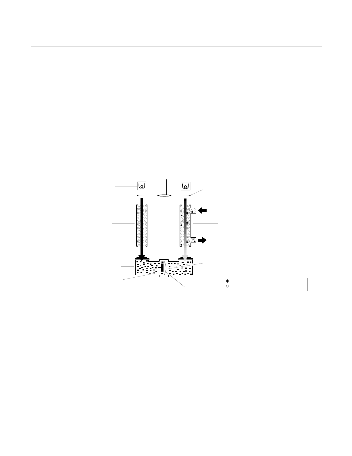
1-3 THEORY OF TECHNOLOGY
• Ammonia: Ammonia dissociation
Inside of the Analyzer Module, two equal-energy
infrared beams are directed through two parallel
optical cells, a flow-through sample cell and a
reference cell. The reference cell may be
sealed or may contain a continuously flowing
reference gas. (See Figure 1-1 below.)
The infrared radiation is interrupted by a
chopper at a frequency of 5 Hz.
Page 16
Instruction Manual
748332-F
April 2003
Model NGA2000 NDIR
During analysis, a portion of the infrared
radiation is absorbed by the component of
interest in the sample. The quantity of infrared
radiation that is absorbed is proportional to the
component concentration.
The detector is a "gas microphone" based on
the Luft principle. The detector is generally
filled with the same gas being analyzed. The
infrared energy is therefore absorbed at the
same wavelengths in the detector as that in the
sample cell, making the detector specific for the
analyzed component. The detector converts the
difference in energy between sample and
reference cells to a capacitance change. This
INFRARED
SOURCE
REFERENCE
CELL
DETECTOR
STATIONARY
PLATE
change, which is proportional to component
concentration, is processed and expressed as
the primary variable on the network.
Other modules comprising the NGA2000 unit
then use this variable for a variety of purposes
(e.g., expressing the gas concentration on the
Front Panel Display or sending it to external
data acquisition devices).
For a general understanding of the electrical
interconnections in the NDIR Analyzer Module,
see Figure 2-4 on page 2-5.
CHOPPER
SAMPLE IN
SAMPLE
CELL
SAMPLE OUT
DIAPHRAGM,
DISTENDED
COMPONENT OF INTEREST
DIAPHRAGM,
DARK STATE
NON-INTERFERING COMPOUNDS
Figure 1-1. NDIR Technology
1-2 Description and Specifications Rosemount Analytical Inc. A Division of Emerson Process Management
Page 17

Model NGA2000 NDIR
1-4 SAMPLE REQUIREMENTS
Maximum allowable sample pressure is 690
hPa-gauge (10 psig) for a standard
configuration NDIR that has a flow restrictor
which sets the flow at between 0.5 L/min. to 1
L/min. Special high pressure cells (up to 10,350
hPa-gauge, 150 psig) are available. Sample
temperature range is 0°C to 55°C, and
maximum dewpoint is 40°C. The sample must
be filtered to exclude particulates larger than 2
microns in size. Consult factory for special
configurations with specifications outside of
those listed above.
1-5 PURGE KITS
A purge kit for the motor source or motor
source/flowing reference cell accompanies
some NDIR modules. The purpose of these kits
is to improve performance and accuracy
through the reduction of ambient CO
Instruction Manual
748332-F
April 2003
interference. They do not provide protection
from explosion hazard. The purge gas vents
into the case, which has no outlet fitting for
these types of purge gases.
1-6 FEATURES
Among the features available in the NDIR
Analyzer Module are:
• Pressure compensation for barometric
fluctuations (optional)
• Flow sensing
2
Rosemount Analytical Inc. A Division of Emerson Process Management Description and Specifications 1-3
Page 18
Instruction Manual
)
748332-F
April 2003
Model NGA2000 NDIR
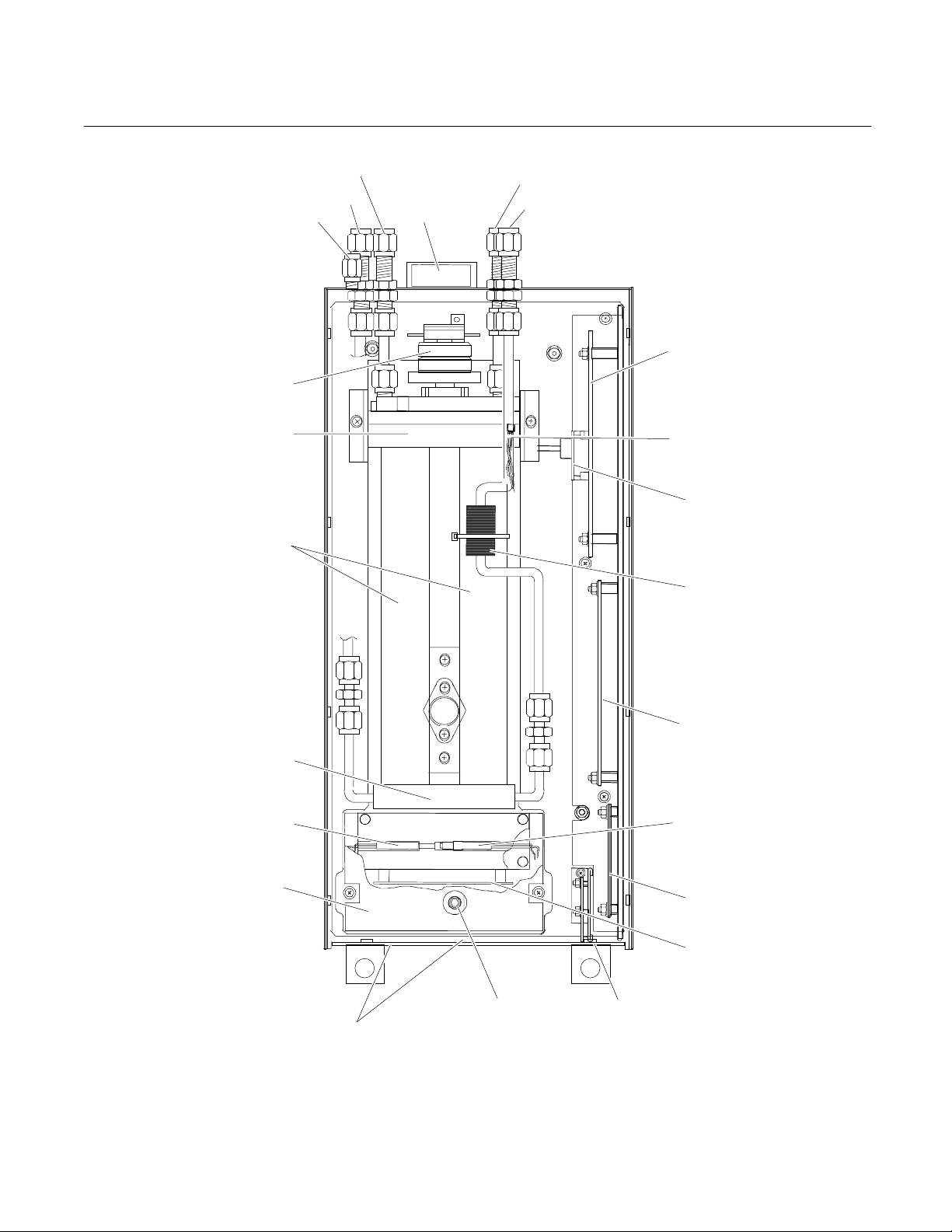
REFERENCE OUT
REFERENCE IN
PURGE GAS IN
FAN
SAMPLE OUT
(BOTTOM)
SAMPLE IN
CHOPPER MOTOR
POWER SUPPLY
BOARD
SOURCE
CASE
TEMPERATURE
SENSOR
CELLS
PRESSURE
COMPENSATION
BOARD (OPTION
FLOW SENSOR
DETECTOR
MICRO BOARD
THERMAL FUSE
DETECTOR COVER
DETECTOR
TEMPERATURE
CONTROL RTD
SIGNAL BOARD
OSCILLATOR
BOARD
SHUTTER ADJUST
ACCESS HOLES
OSCILLATOR
TUNE ADJUST
NETWORK INPUT
MODULE
Figure 1-2. NGA2000 NDIR Analyzer Module (Typical - Actual Configuration May Vary)
1-4 Description and Specifications Rosemount Analytical Inc. A Division of Emerson Process Management
Page 19

Model NGA2000 NDIR
1-7 SPECIFICATIONS
a. General
Measurement Species:.................. Heteroatomic gases such as ammonia (NH
Ranges:......................................... 10 ppm fullscale to 100% fullscale (application-dependent); 4
Repeatability:................................. ±1% of fullscale (at constant temperature)
Minimum Detectable Level:........... 0.1% CO
Noise: ............................................ <1% of fullscale, peak-to-peak
Linearity:........................................ ±1% of fullscale with 4th order polynomial
Response Time: ............................ .05 to 30 seconds (selectable) for 0 to 90% of fullscale
Drift (Zero and Span):.................... <±1% of fullscale/24 hours at constant temperature (application
Effect of Temperature:................... <±1% of fullscale over any 10°C interval for rate of change no
Environment: ................................. Location - Class B controlled, indoor, non-hazardous
Ambient Temperature:................... 0 to 45°C (32 to 113°F)
Effect of Flow:................................ <1% of range when sample flow rate is changed by ≤250 ml/min.
Power Requirements:....................24 VDC ±5%, 100 W max.; ripple and noise: <100 mV peak-to-
Instruction Manual
April 2003
), carbon dioxide
3
(CO
), carbon monoxide (CO), carbon monoxide + carbon dioxide
2
ethylene (C
and sulfur dioxide (SO
fullscale selections, including suppressed zero ranges
dependent);
<±2% of fullscale/week at constant temperature (application
dependent)
greater than 10°C per hour (application dependent)
(No effect if flow rate is between 0 and 500 ml/min.)
peak; line and load regulations: <±1%
), hexane (C6H14), methane (CH4), nitric oxide (NO)
2H4
)
2
(at 1 atm. sample pressure; application dependent)
2
748332-F
b. Physical
Case Classification:....................... General purpose for installation in weather-protected areas
Dimensions:................................... See Outline and Mounting Dimensions, Figure 2-5 on page 2-6
Weight: .......................................... Standard: 11 kg (24.2 lbs.); extended: 12.5 kg (27.5 lbs.)
Mounting:....................................... Inside a Platform or custom-installed in a panel
Maximum Length of LON Cable:... 1600 m (1 mile) between Analyzer Module and Platform
c. Sample
Temperature:................................. Non-flammable 0°C to 55°C (32°F to 138°F)
Flow Rate: ..................................... 500 to 1400 ml/min.
Pressure:....................................... Maximum 690 hPa-gauge (10 psig), higher pressure in pressurized
cell applications
Particulates:...................................filtered to <2 microns
Dewpoint:....................................... <40°C (104°F), no entrained liquid
Materials in Contact with Sample:.Gold plated Pyrex, sapphire, quartz, Irtran, FEP Teflon, Viton-A,
316 stainless steel
See the Preface section of the Platform manual for specifications regarding Platform-related components
(e.g., case dimensions) and the I/O Module manual for specifications regarding I/O (e.g., relay outputs).
Rosemount Analytical Inc. A Division of Emerson Process Management Description and Specifications 1-5
Page 20

Instruction Manual
748332-F
April 2003
Model NGA2000 NDIR
1-6 Description and Specifications Rosemount Analytical Inc. A Division of Emerson Process Management
Page 21
Model NGA2000 NDIR
Instruction Manual
748332-F
April 2003
SECTION 2
INSTALLATION
WARNING.
Before starting to install this equipment,
read the “Essential Instructions” on the
inside cover and the Safety Summary
beginning on page P-2. Failure to follow the
safety instructions could result in serious
injury or death.
2-1 UNPACKING
If the NDIR Analyzer Module is received as a
separate unit, carefully examine the shipping
carton and contents for signs of damage.
Immediately notify the shipping carrier if the
carton or contents is damaged. Retain the
carton and packing material until all components
associated with the Analyzer Module are
operational.
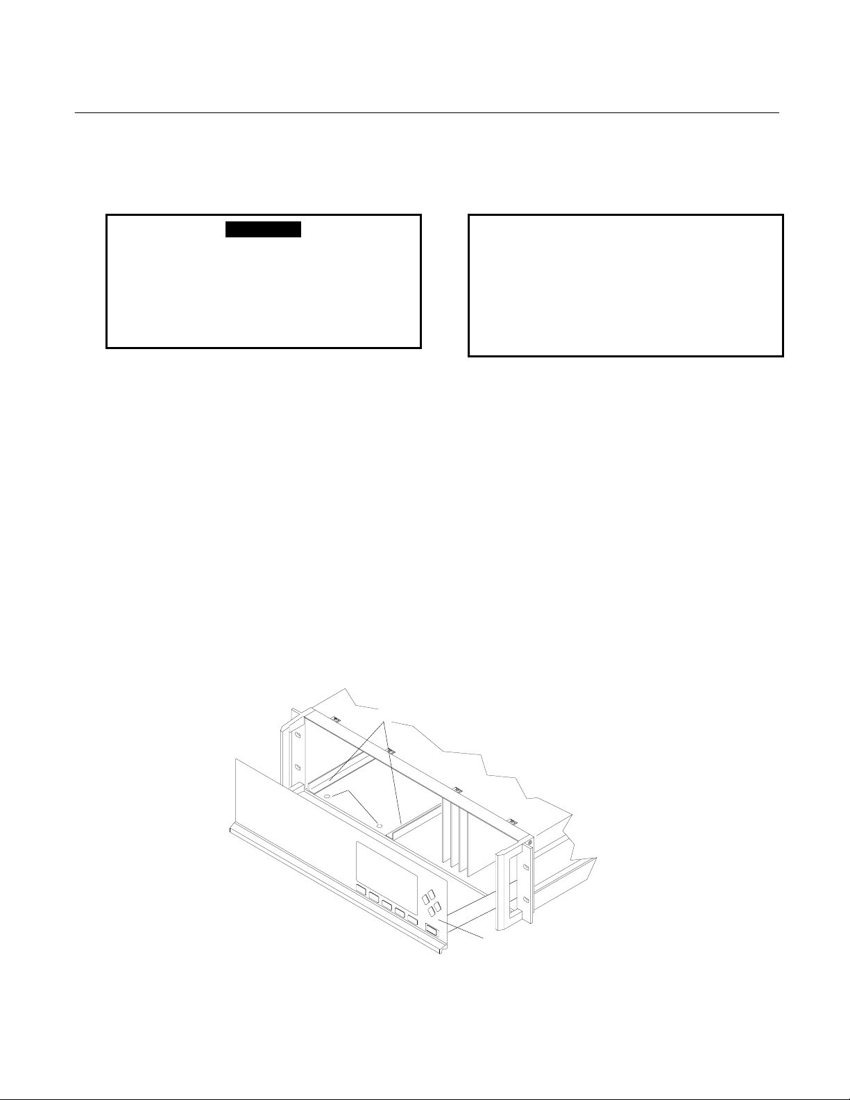
2-2 ASSEMBLY
If the NDIR Analyzer Module requires assembly
with other components (e.g., the Platform and
associated I/O Modules), do so at this time.
Following the guides on the bottom left and
bottom center of the Platform, carefully slide the
Analyzer Module halfway into place.
ANALYZER M ODULE GUIDES
PIN SEATS
CAUTION.
HAND INJURY HAZARD
Do not place hands or fingers in Platform
front handles when the front panel is open.
Dropping front panel while hand or fingers
are inside either handle can cause serious
injury.
Lift the spring-loaded pins on the front of the
Analyzer Module, and carefully slide it the rest
of the distance. Secure the module in position
by releasing the pins, which seat in the available
holes in the bottom of the case (see Figure 2-1,
below). If the module and Platform are difficult
to assemble, remove the module, ensure the
top cover of the module is firmly seated on the
hold-down screws, and repeat the assembly
procedure.
Install I/O Module(s) according to guidelines in
the I/O manual. After startup and calibration
have been performed, secure the front panel
with the six screws provided.
DISENGAGED FRONT PANEL
Figure 2-1. Analyzer Module Installation into Instrument Platform
Rosemount Analytical Inc. A Division of Emerson Process Management Installation 2-1
Page 22

Instruction Manual
748332-F
April 2003
2-3 LOCATION
Install the NDIR Analyzer Module in a clean,
non-hazardous, weather protected, vibration
free location free from extreme temperature
variations. For best results, install the
instrument near the sample stream to minimize
sample transport time. Operating ambient
temperature is 0
Sample dewpoint is 40°C or less.
Unrestricted air flow in the rear of the Analyzer Module is critical to its performance
and reliability..
o
C to 45oC (32oF to 113oF).
NOTE
Model NGA2000 NDIR
negated if the same flow rate is used for
sample, zero and span gases. But, if flow is
high enough to cause elevated pressure,
careful control (tighter tolerance) of flow rate
is required to avoid errors.
If flow is kept at or below 2 SCFH (1 L/min),
sample and instrument temperatures reach
equilibrium regardless of stream
temperature (within specifications; 0 to
55°C). At extremely high flow rates, this
may not be true, although no such effect
has been noted up to 18 SCFH (9 L/min).
See Table 2-1 on page 2-3 for cell purging
times at atmospheric sample pressure .
2-4 GAS SPECIFICATIONS
a. Calibration Gases
All applications require a zero standard gas
to set the zero point on the display and
external data acquisition devices. if the
factory provided Calibration and Data Sheet
(in the rear of the manual) specifies a
background gas, use this as a zero gas. If
a background gas is not specified, use dry
nitrogen.
Span gas should be between 75% and
100% of fullscale span. Flowing reference
(if used) should be dry nitrogen.
b. Flow Rate
Recommended sample flow rate is 1 to 2
SCFH (500 TO 1000 cc/min). A lower flow
rate will not affect readings but may result in
an undesirable time lag. Excessive flow
can produce increases cell pressurization
and reading error.
At higher cell pressures, the nonlinearity of
the calibration curve increases. Therefore,
the calibration curve should be redrawn for
higher flow rates. Also, the effect of
increased cell pressurization can be
c. Sample Pressure/Filtration
Sample should be introduced to the
Analyzer Module at a maximum 690 hPagauge (10 psig). Pressurized applications
are available, which require pressurized
cells and careful control of flow rates,
consult factory for these applications.
Sample should be filtered for particulates
down to two microns.
d. Leak Test
The Analyzer Module is completely tested
at the factory for gas leakage. The user is
responsible for testing for leakage only at
the inlet and outlet fittings on the rear panel.
The user is also responsible for internal leak
testing periodically and if any internal
pneumatic components are adjusted or
replaced (with a test procedure chosen by
the user).
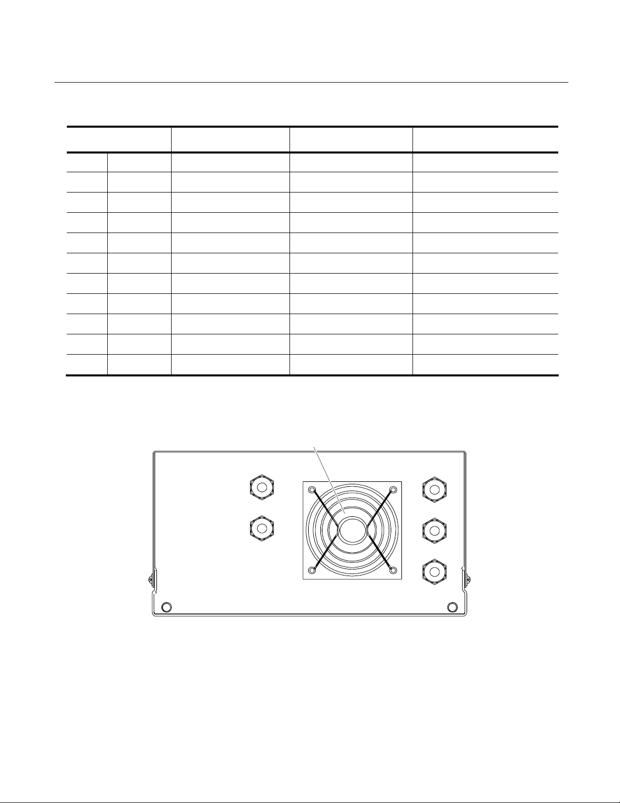
2-5 GAS CONNECTIONS
(See Figure 2-2 on page 2-3) Connect inlet
and outlet lines for sample/zero/span and
flowing reference (if applicable) to
appropriately labeled fittings on the rear
panel. All four connections are 1/4 inch
ferrule-type compression fittings.
2-2 Installation Rosemount Analytical Inc. A Division of Emerson Process Management
Page 23
Instruction Manual
Model NGA2000 NDIR
CELL LENGTH
mm inch without inlet tube cell with inlet tube at 750 mm Hg
3 0.118 0.85 12 2 sec.
4 0.157 1.14 12 2 sec.
8 0.315 2.28 13 2 sec.
16 0.630 3.56 16 2 sec.
32 1.25 9.12 20 2 sec.
64 2.52 18.24 25 3 sec.
128 4.03 35.48 44 3 sec.
232 9.13 65.12 73 6 sec.
343 13.50 97.76 105 13 sec.
381 15.00 108.60 116 14 sec.
Table 2-1. Cell Purging Times at Atmospheric Sample Pressure
CELL VOLUME
CC
TOTAL VOLUME
CC
TIME FOR 2 VOLUMES
@ 2 SCFH (1L/MIN)
748332-F
April 2003
FAN
OUT
IN
SAMPLE
10 PSI MAX
(69 kPa MAX)
OUT
REFERENCE
IN
10 PSI MAX
(69 kPa MAX)
PURGE IN
15 PSI (103 kPa) MAX
Note: Reference and purge gas connections are applicable only to certain applications.
Figure 2-2. NDIR Back Panel
Rosemount Analytical Inc. A Division of Emerson Process Management Installation 2-3
Page 24
Instruction Manual
748332-F
April 2003
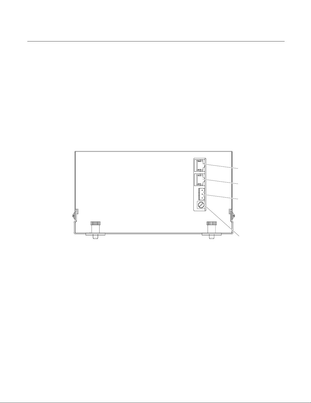
2-6 ELECTRICAL CONNECTIONS
NOTE
Electrical connections must be in compliance with National Electrical Code
(ANSI/NFPA 70) and/or any applicable national or electrical codes.
Two electrical connections are required on the
Analyzer Module; POWER and NETWORK.
Model NGA2000 NDIR
See Figure 2-3 below. On the Analyzer
Module, two NETWORK connections are
available, either of which is appropriate for : 1)
interconnection with Backplane of the
Platform (see Platform instruction manual) or
2) "daisy chaining" with other NGA2000
components.
Connect Analyzer Module POWER 24 VDC
power source, either the Platform or external
power source.
NETWORK 1
NETWORK 2
POWER
FUSE
Figure 2-3. NDIR Front Panel Electrical Connections
2-4 Installation Rosemount Analytical Inc. A Division of Emerson Process Management
Page 25
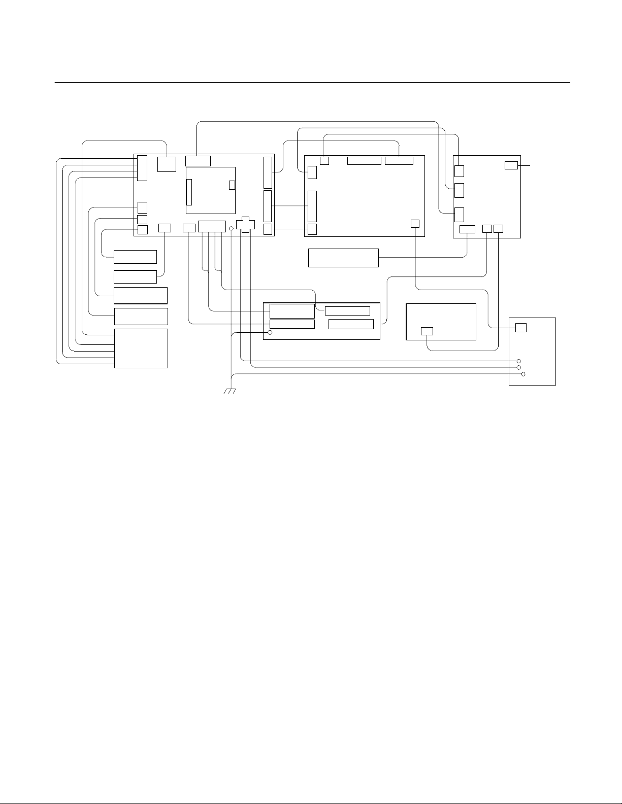
Model NGA2000 NDIR
ASSY
SAMPLE J2-1
SOURCE J2-2
REFERENCE J2-3
SOURCE J2-4
FLOW SENSOR
FAN ASSEMBLY
MODULATION CHECK
HEATSINK/SOURCE
MOTOR ASSEMBLY
REF SOURCE
SAMPLE SOURCE
J2
J1
J15
J14
RESISTOR
DRIVER
SOUR CE
J4
POWER
SUPPLY
BOARD
J6 J10
J9
PRESSURE
COMPENSATION
BOARD
J7
1 2 3 4
J5
1 2
CHASSIS
GROUND
J3
J11
J8
FUSE, THERMAL
CUTOFF
RTD, TEMP CTRL
J4 J5 J6
J1
COMPUTER BOARD
J2
J3
CASE TEMPERATURE
SENSOR °C
HEAT ER
DETECTOR BASE
SENSOR °C
J7
OSCILLATOR
BOARD
J1
Instruction Manual
748332-F
April 2003
RECORDER
J5
J7
SIGNAL
J4
BOARD
J6
J3 J1
J2
OUTPUT
J5
LON/POWER
BOARD
Figure 2-4. NDIR Wiring Diagram
Rosemount Analytical Inc. A Division of Emerson Process Management Installation 2-5
Page 26
Instruction Manual
[
]
[28]
748332-F
April 2003
Model NGA2000 NDIR
8.4
[213]
[208]
6.2
[157]
4.3
[109]
1.1
[28]
20.0
[508.0]
STAND ARD
24.8
[628.7]
EXTENDED
6.0
[152]
17.41
[142.2]
STANDARD
.6
[15]
1.1
1.1
[27]
8.4
213
G. POWER CABLE TO NETWORK.
F. NETWORK CABLE CONNECTIONS TO PLATFORM.
E. PURGE GAS IN: 1/4" O.D. TUBE FITTING.
D. REFERENCE IN: 1/4" O.D. TUBE FITTING.
C. REFERENCE OUT: 1/4" O.D. TUBE FITTING.
B. SAMPLE OUT: 1/4" O.D. TUBE FITTING.
A. SAMPLE IN: 1/4" O.D. TUBE FITTING.
5. MODULE TO BE INSTALLED WITHIN ±15° OF HORIZONTAL.
4. POWER REQUIREMENTS: 24 VDC 3.5 A.
3. ELECTRICAL INSTALLATION MUST BE IN COMPLIANCE WITH NATIONAL ELECTRICAL
CODE (ANSI/NFPA 70) AND/OR ANY APPLICABLE NATIONAL OR LOCAL CODES.
2. MODULE IS NOT WEATHERPROOF.
1. APPROXIMATE WEIGHT: 24.2 LB (11.0 kg).
8.2
5.6
[143]
.6
[15]
22.41
[569.2]
EXTENDED
2.8
[71]
1.0
[25]
[13]
.5
1.6
[40]
DIMENSIONS
INCH
[mm]
Figure 2-5. Outline and Mounting Dimensions
2-6 Installation Rosemount Analytical Inc. A Division of Emerson Process Management
Page 27

Model NGA2000 NDIR
STARTUP AND OPERATION
Instruction Manual
748332-F
April 2003
SECTION 3
3-1 OVERVIEW
Prior to initial startup, the user should leak test
the module as outlined in Section 2.
For the remainder of this section, Analyzer
Module interconnection with a Platform or
some interfacing component will be assumed.
Display and Keypad information shall refer to
that which the user can expect to see and do
with regard to the Front Panel of the Platform.
(For a complete description of Platform Front
Panel controls and indicators, see Section 1
of the Platform Components instruction
manual.)
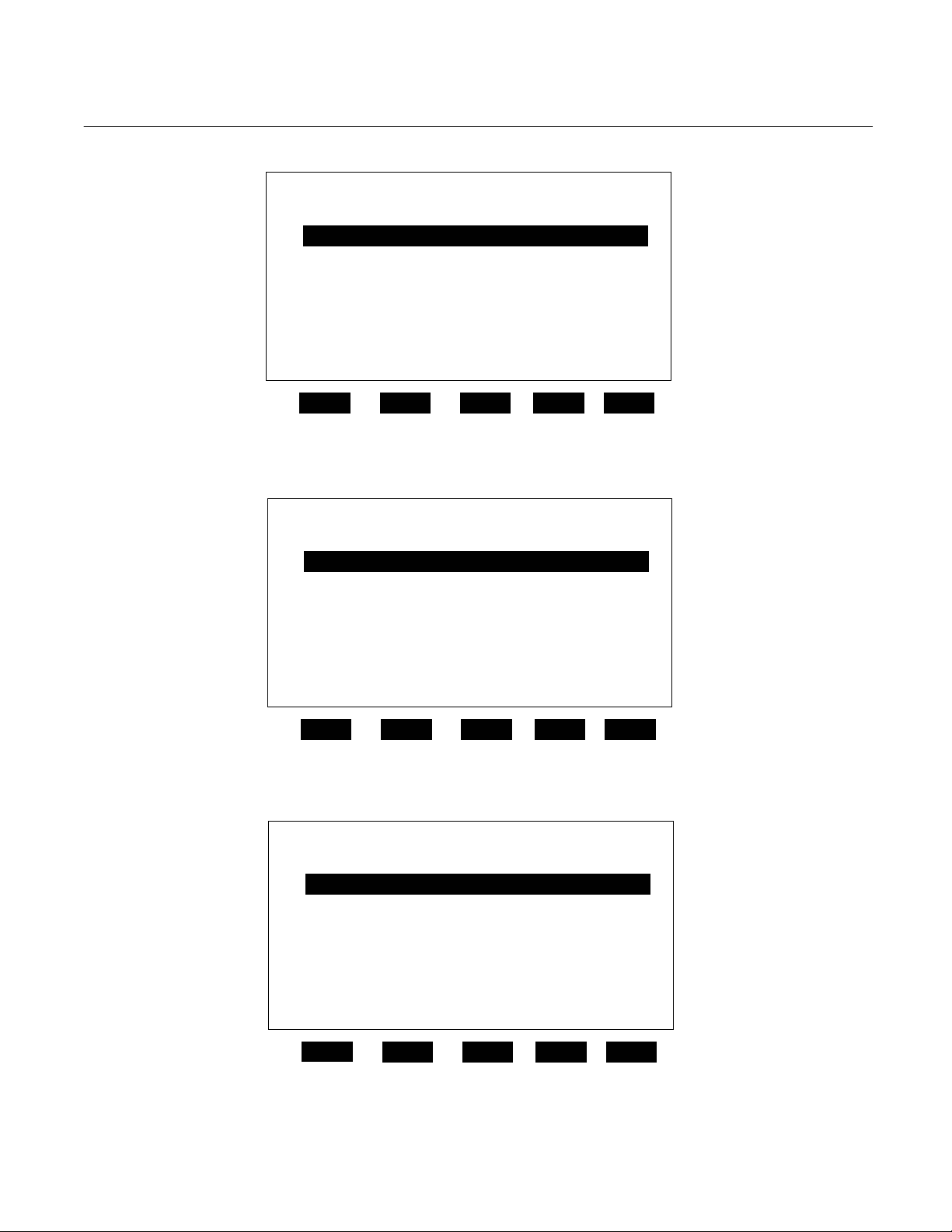
3-2 DISPLAY SCREENS
Three kinds of Display screens are available
to the user (See Figure 3-3 through Figure
3-6.):
• Run Mode
• Menu
• Help
b. Menu Displays
The Menu structure enables the user to
access data and functions, and put
information onto the network.
The Main Menu (see Figure 3-2 on page
3-2) is subdivided into three levels of
control based generally on which
personnel is likely to use it: Basic
Controls, Expert Controls and Setup, and
Technical Controls. (See Figure 3-3
through Figure 3-5.) Many layers of the
menu structure are described at
appropriate places throughout this
manual.
From the Run Mode display, press the
MENUS softkey to gain access to the
Main Menu. (See Figure 3-2 on page 3-
2.)
c. Help Displays
The Help structure is on-line "tutorial,"
context-sensitive and
topic-interconnected, so that the user can
practically operate NGA2000 without
need of an instruction manual.
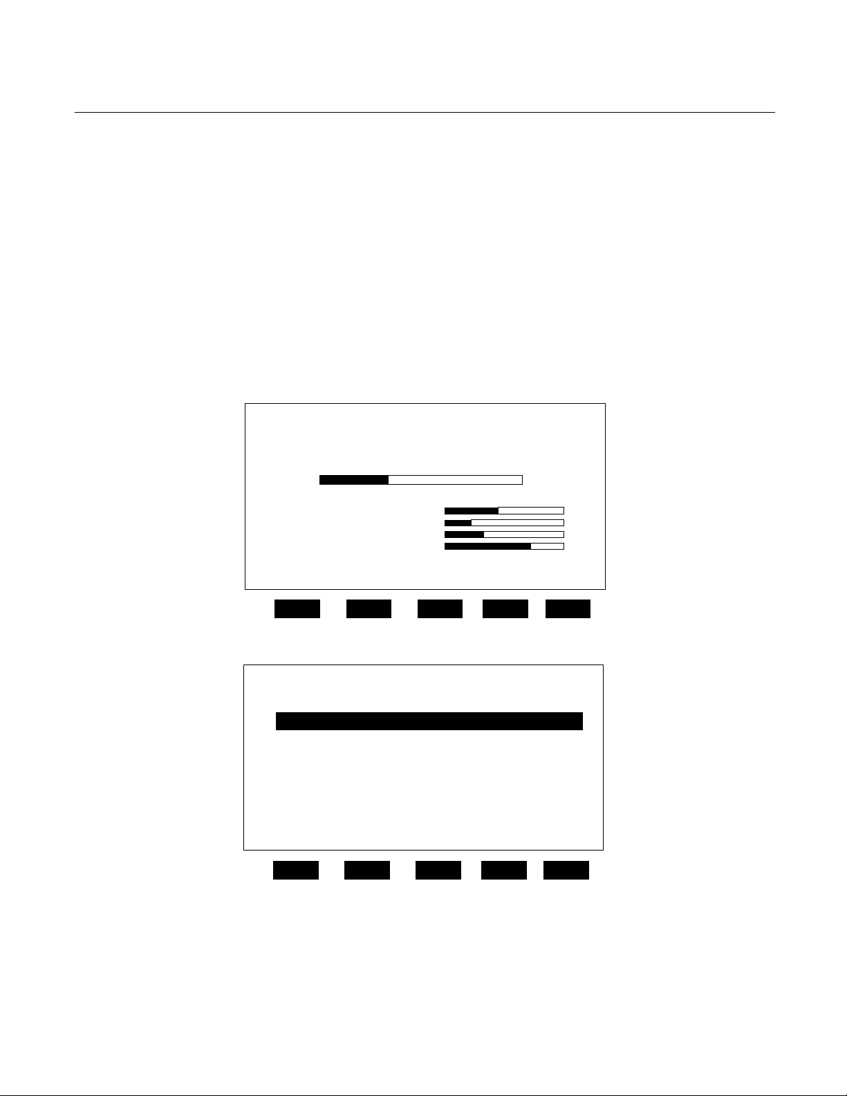
a. Run Mode Display
The Run Mode is the normal mode of
operation. In this mode, the Display will
show current gas measurement, the
component of interest, the current
operations of the softkeys, a graphic bar
representing the displayed concentration
as a percent of fullscale, and up to 4 userselectable secondary variables and
associated bargraphs.
If more than one Analyzer Module is
connected to the system, the Run Mode
display will show as many as four gas
measurements on a single screen. Alarm
messages may also appear on the display
(See Table 3-1 on page 3-5)
Rosemount Analytical Inc. A Division of Emerson Process Management Startup and Operation 3-1
3-3 STARTUP PROCEDURE
Introduce zero gas into SAMPLE INLET and
reference and source purge gas, if applicable,
into their respective inlets. Ensure that gas
pressures are set to requirements listed on
the Specifications page of the Preface section
of this manual.
Apply power to the NDIR Analyzer Module. If
it is associated with a Platform, do this by
plugging in the Platform to a power source.
The Platform has no ON/OFF power switch.
Once power has been supplied to the
Platform, the NDIR Analyzer Module will be
energized.
If the user's system contains only one
Analyzer Module, all system components, the
Page 28
Instruction Manual
y
y
y
y
748332-F
April 2003
Model NGA2000 NDIR
Controller Board and the network "self-install"
(bind together) during initial startup. If the
system contains more than one Analyzer
Module, the startup procedure will interrogate
the network to locate and identify all
components on the network. The user will
have to bind appropriate combinations of
Diagnostic Service menus. If both settings
are within ±5% tolerance of factory setting, go
to Section 3-4 below for binding and Section
3-5 on page 3-4 for calibration. If not, refer
first to Section 4-11 on page 4-6 for
instructions about oscillator tune/source
balance shutter adjustments.
components after the startup sequence.
After the warm-up period (about one hour for
the NDIR Analyzer Module), all modules are
completely functional.
Check the tune and detector signal values
against the factory settings listed in the
3-4 BINDING
To achieve full coordination between Analyzer
Modules and associated I/O Modules, the
user must bind those components together in
the System Set Up portion of the Technical
Configuration Menu in software.
Analyzer PQ 322-14
23.2 % CO
Secondar
Secondar
Secondar
Secondar
Display Parms. Menu Dual Info
F1
0 ppm
Variable: XXXX
Variable: XXX
Variable: XXXX
Variable: XXXX
F2 F3 F4 F5
50
Figure 3-1. Run Mode Display
23.2 % CO Analyzer XXXXXXXX
Main Menu
Basic Controls
Expert controls and setup ...
(Operational configuration)
Technical level configuration ...
(Diagnostic and manufacturing/service)
Delete alarm message!
Display Parms. Info
F1
F2 F3 F4 F5
Figure 3-2. Main Menu Display
3-2 Startup and Operation Rosemount Analytical Inc. A Division of Emerson Process Management
Page 29
Model NGA2000 NDIR
p
p
g
23.2 % CO Analyzer XXXXXXXX
Measurement range Numbers:
Range upper limit: 25%
Range and functional control: Local
Calibration…
Status: Ready
Home Escape Zero Span Info
F1
Figure 3-3. Basic Controls Menu
23.2 % CO Analyzer XXXXXXXX
Expert analyzer controls ...
Auxiliary module controls ...
System set up ...
Analyzer module set up ...
Auxiliary module set up ...
Home Escape Info
F1
Basic Controls
F2 F3 F4 F5
Ex
ert controls and setu
F2 F3 F4 F5
Instruction Manual
748332-F
April 2003
Figure 3-4. Expert Controls and Setup Menu
23.2 % CO Analyzer XXXXXXXX
Technical confi
System set up ...
Service menus...
Diagnostic menus...
Other module diagnostic menus...
listing of all modules...
Status: normal
Home Info
F1
F2 F3 F4 F5
uration menu
Figure 3-5. Technical Level Configuration Menu
Rosemount Analytical Inc. A Division of Emerson Process Management Startup and Operation 3-3
Page 30

Instruction Manual
p
748332-F
April 2003
3-5 CALIBRATION
Calibration can be executed from the Basic
Controls menu. Calibration gas data can be
entered only through the Expert Controls
and Setup menu.
To calibrate the Analyzer Module, introduce
zero gas into the SAMPLE INLET, and do the
following:
1. If the multi-Analyzer Module, split Run
Mode display is shown, press the
DISPLAY softkey until the desired
Analyzer's Run Mode display is
acquired.
2. Press the MENUS softkey to enter the
Main Menu and make the following
selections from the Main Menu: Expert
Controls and Setup, Analyzer Module
Setup, Calibration Gases.
3. Input appropriate data in the
Calibration Gas List menu.
4. Press the HOME softkey to return to the
Main Menu.
23.2 % CO Analyzer XXXXXXXX
The Main Menu for the analyzer system.
Note that this menu refers to the particular
analyzer selected from the run screen, when
used in a system. The softkey marked “HOME”
will always return you to this screen.
Help menu system...
Help on help...
Keyboard controls...
Editing controls...
Home Escape Map
F1
Model NGA2000 NDIR
Main Menu Hel
F2 F3 F4 F5
Figure 3-6. Typical Help Screen
6. Press the ZERO softkey to enter the
Analyzer Zero menu, press ZERO
again and wait.
7. Introduce span gas into the SAMPLE
INLET, press SPAN softkey to enter the
Analyzer Span menu, press SPAN
again and wait.
8. Press HOME to re-enter the Main
Menu.
9. Press DISPLAY softkey for the Run
Mode display.
If the user is unable to calibrate the Analyzer
Module (i.e., when ZERO or SPAN is initiated,
nothing happens), a possible solution relates
to the use of an incorrect gas for zeroing or
spanning (e.g., using a high concentration gas
to zero or a zero gas to span the Analyzer
Module). Simply recalibrating with the
appropriate gas(es) will not correct the
problem because the ZERO OFFSET or
SPAN FACTOR has been set to an extreme
value in the process.
To remedy the problem, do the following:
5. Use the ↓ arrow key to select Basic
Controls.
3-4 Startup and Operation Rosemount Analytical Inc. A Division of Emerson Process Management
1. Select the following from the Main
Menu: Expert Controls and Setup,
Page 31

Model NGA2000 NDIR
Instruction Manual
748332-F
April 2003
Analyzer Module Set Up, and
Calibration Parameters.
2. Using the ↓ arrow, select Zero
Ranges, press ENTER and, using the
up/down arrows, toggle to
SEPARATE. Do the same for the
Calibrate Ranges selection. Do not
press ESCAPE at any time unless
retention of prior settings is desired.
3. Return to the Main Menu and make
the following selections: Expert
Controls and Setup, Expert Controls,
CAL DATA softkey, FACTORS
softkey, and Range 1 (2, 3, 4) Factors
(do Steps 4 and 5 for each range).
4. Select Zero Offset, press ENTER,
adjust the value to 500000 with the ↑
and ↓ arrow keys, and press ENTER.
Do not press ESCAPE at any time
unless retention of prior settings is
desired.
DISPLAY MESSAGE DESCRIPTION TYPE
BAROMETER System Barometer WARNING
CASE TEMP Case Temperature WARNING
CHOP SPEED Chopper Speed WARNING
CRUDE NOISE Calculated Noise WARNING
DET SIG Detector Signal WARNING
DET TEMP Detector Temperature WARNING
LIN ERROR Linearizer Error WARNIN G
N15 VOLTS Power Supply, -15V WARNING
P12 VOLTS Power Supply, +12V WARNING
P15 VOLTS Power Supply, +15V WARNING
P24 VOLTS Power Supply, +24V WARNING
P5 VOLTS Power Supply, +5V WARNING
PERCENT MOD Percent Modulation WARNING
RAW SIGNAL Raw Signal WARNING
SVFLOW Sample Bypass Flow WARNING
SW ERROR Software Error FAILURE
Table 3-1. NDIR Analyzer Module Alarms
5. Refer to the Data Sheet in the rear of
this manual for Span Factors as
originally set at the factory. Select
Span Factor, press ENTER, adjust
the value to match the values on the
Data Sheet with the ↑ and ↓ arrow
keys, and press ENTER. If Data
Sheet is not available, enter 0.000015
with the ↑ and ↓ arrow keys, and
press ENTER. Do not press
ESCAPE unless retention of prior
settings is desired.
6. Attempt to recalibrate the Analyzer
Module according to the procedure
outlined at the beginning of Section 35 on page 3-4. If recalibration fails,
return to the Range Factors menu,
readjust factors and try calibrating
again.
Another cause of failure to calibrate is the
following: The value for "Maximum range" is
lower than the upper limit value for the range
in use. See the Range Settings menu for
this information.
Rosemount Analytical Inc. A Division of Emerson Process Management Startup and Operation 3-5
Page 32

Instruction Manual
748332-F
April 2003
3-6 LINEARIZATION
The NDIR Analyzer Module can be operated
in linear and non-linear mode. Linearization
can be toggled ON/OFF in the Expert
Controls menu. In the OFF position,
linearization is disabled for all ranges, and the
component of interest is measured in percent
of fullscale. In the ON position, measurement
is in engineering units: Either ppm or percent
of concentration.
The NDIR Analyzer Module is linearized with
the following fourth-order polynomial:
Y = A
o + A1X + A2X
Where:
X = the normalized non-linear input
A
O, A1, A2, A3, A4 = linearization
coefficients
Y = the normalized linear output
Linearization coefficients can be developed
and stored for each range through the Expert
Controls menu. The operating range is
selected by entering RANGE = 1, 2, 3 or 4 in
the Range Mode section that that menu.
2
+ A3X3 + A4X
Model NGA2000 NDIR
A0 = 0.00000
A1 = 1.00000
A2 = 0.00000
A3 = 0.00000
A4 = 0.00000
To calculate linearization coefficients other
than those installed at the factory, take a
minimum of 11 data points. (A more accurate
curve can be obtained as the user
approaches 21 data points. If urgent, a curve
can be created with as few as four points, but
this is only a temporary fix. A more accurate
curve should be created as soon as possible.)
4
These data points can be obtained with an
accurate gas divider or other flow mixing
device. Before calculating coefficients, the
data must be normalized to ranges of 0 to 1
units for both percent and concentration
readings. Then, the axis must be reversed as
illustrated in Figure 3-7 on page 3-7 and
Figure 3-8 on page 3-7. A multiple linear
regression is then used to calculate
coefficients. (For example: If the range is 0
to 5000 ppm and readings are 0 to 100%,
then divide all of the concentrations by 5000
and the readings by 100. Put the normalized
concentrations on the Y-axis and the
normalized readings on the X-axis.)
Coefficients for each selected range are
automatically used when the module is in
Linearization Mode. The user instructs the
Analyzer Module as to which set of
coefficients are to be used for each range.
Maximum dynamic range is 3:1.
When ordered, special linearization
coefficients for non-standard fullscale ranges
are entered in the appropriate range(s) at the
factory. If a range is not specified, the set of
coefficients will be for Range 4.
The operator may want the module to output
measurement in engineering units (ppm).
This response is linear over the operating
range. The following coefficients will make no
correction to the non-linear response, but will
cause the NDIR Analyzer Module to output
gas measurement in engineering units:
3-6 Startup and Operation Rosemount Analytical Inc. A Division of Emerson Process Management
These data points can be entered into any
program capable of computing a fourth-order
polynomial curve. This curve will be the
mirror image of the curve on the Calibration
and Data Sheet provided in the rear of this
manual; however, the linearization coefficients
will be different. Use the coefficients
calculated with the curve in the polynomial
shown on the previous page.
After taking the data points, the operator may
determine coefficients for user-specific gas by
either using any program capable of
calculating a fourth-order curve fit or calling
the factory to have the specific coefficients
calculated.
When entering the operator-determined
coefficients, note that the microprocessor only
recognizes five significant digits to the right of
the decimal point (e.g., 0.12345).
Page 33

Model NGA2000 NDIR
Instruction Manual
748332-F
April 2003
100 %
READING
% FULLSCALE
50 %
0 %
0 500 1000 1500 2000 2500 3000 3500 4000 4500 5000
Display ppm
CONCENTRATION
ppm
Figure 3-7. Typical Linearization Curve, Linearizer OFF
CONCENTRATION
NORMALIZED
1
0.9
0.8
0.7
0.6
0.5
0.4
0.3
0.2
0.1
0
0 0.1 0.2 0.3 0.4 0.5 0.6 0.7 0.8 0.9
READINGS, NORMALIZED
(Axis Reversed)
Figure 3-8. Operator-Determined Linearization Curve (Normalized)
Rosemount Analytical Inc. A Division of Emerson Process Management Startup and Operation 3-7
Page 34

Instruction Manual
748332-F
April 2003
Model NGA2000 NDIR
3-7 ROUTINE OPERATION
Set the NDIR Analyzer Module for desired
operating range. Zero and span the module,
and then supply sample gas to the SAMPLE
INLET at the rear of the module. The NDIR
Analyzer Module will now automatically and
continuously analyze the sample stream.
As a check of instrument performance, the
operator should keep a log of zero/span
status.
Maximum permissible interval between
calibrations depends on the analytical
accuracy required. A frequency of once every
24 hours is recommended initially, and that
practice should be continued unless
experience indicates that some other interval
is more appropriate.
Readout accuracy is directly proportional to
change in barometric pressure (i.e., a change
in cell pressure of 7.6mm of mercury will
result in a readout error of about 1% of
reading). Therefore, if barometric pressure
changes significantly, a recheck of calibration
against a span gas is advised. Also, an
optional Pressure Compensation Board is
available that electronically compensates.
The Analyzer Module will not allow the user to
increase the upper limit of a range beyond the
"maximum range" software setting. To
change the "maximum range" value, select
the following from the Main Menu: Technical
Configuration Menu, Service Menu,
Manufacturing Data, Analyzer Manufacturing
Data. Select Maximum Range, and use the
arrow keys to scroll the indicated value. The
same applies for "minimum range" setting.
3-8 Startup and Operation Rosemount Analytical Inc. A Division of Emerson Process Management
Page 35

Model NGA2000 NDIR
4
Basic controls...
Expert controls and setup...
(Operational configuration)
Technical level configuration...
(Diagnostic and manufacturing/service)
Enter your security code with softkeys.
Security codes are set in the system setup
menu in the Technical level menus.
Press five characters when Security code
says READY. Press six to return to “READY”.
Security code: 54321
Measurement range number: 1
Range upper limit: 10 ppm
Range and functional control: LOCAL
Zero gas concentration: 0 ppm
Span gas concentration: 9.89 ppm
Ranges with valid calibration: 1&2
Calibration status: Ready
If it won’t calibrate...
Status: Ready
Are you sure?
You must have zero gas flowing
through the analyzer.
This control does NOT control any autocal. Module bound to this analyzer!
If you are sure, press ZERO again now.
Press left arrow key when you are
done.
Calibration status: Ready
Error message for last zero: 24-08-94
Main Menu
Basic level security
(expert, technical)
Basic controls
ZERO
Analyzer Zero
PARMS
Are you sure?
You must have zero gas flowing
through the analyzer.
This control does NOT control any autocal. Module bound to this analyzer!
If you are sure, press SPAN again now.
Press left arrow key when you are
done.
Calibration status: Ready
Error message for last zero: 24-08-94
Current measurement parameters
Measurement range number: 1
Expert analyzer controls...
Auxiliary module controls...
System set up...
Analyzer module set up...
Auxiliary module set up...
Local I/O set up...
Range change control: Local
Measured Gas: CO2
Linearization mode: ON
Gas Measurement Setup: ON
Analyzer operational state: Normal
Analyzer alarm state: Normal
Alarms report: Failure
Expert controls and setup
SPAN
Analyzer Span
MORE
Technical configuration menu
System set up...
Service menus...
Diagnostic menus...
Other module diagnostic menus...
Listing of all modules...
Expert and Technical menus follow in
succeeding flow charts.
Check that you are flowing the correct gas, and the
gas concentration is what it is supposed to be.
Make sure that the reading is stable before
starting. If you have changed the range fullscale
value or any linearizer coefficients, or enabled or
disabled it, or done anything else that would affect
how it measures the gas, you may have made it
hard for the analyzer to calibrate. If so, manually
adjust the coefficients until the readings are close
to correct, and try again.
If it won’t calibrate...
Instruction Manual
748332-F
April 2003
Current measurement parameters
Response time: 2.0 Secs
Sample flow: 1000 ml/min.
Sample pressure: 12.3 kPa
Case Temperature: 55.3!C
Figure 3-9. Display Screens (1 of 5)
Rosemount Analytical Inc. A Division of Emerson Process Management Maintenance and Service 3-9
Page 36

Instruction Manual
748332-F
April 2003
#1
Zero/Span diagnostic data
Date of last zero: 24-08-94
Error message for last zero: 24-08-94
Error percentage for last zero: 5%
Raw signal at last zero: 500000
Last zero gas would read: -0.83 ppm
Date of last span: 24-08-94
Error message for last span: Great!
Error percentage for last span 5%
Raw signal at last span: 500000
The last span gas would read: 11.3 ppm
FACTORS
#3
Calibration Factors
Range 1 factors...
Range 2 factors...
Range 3 factors...
Range 4 factors...
Zero compensation factor: 1
Span compensation factor: 1
From MAIN MENU ⇒
Measurement range number: 1
Range lower limit: 0 ppm
Range upper limit: 10 ppm
Linearizer: ON
Range and functional control: LOCAL
Zero/Span calibration...
Ranges with valid calibration: 1&2
Physical measurements...
CAL DATA
Expert controls
CAL
Expert controls and setup
Expert analyzer controls...
Auxiliary module controls...
System set up...
Analyzer Module set up...
Auxiliary Module set up...
Local I/O set up...
Auxiliary module controls
This screen selects any module with a
control screen. This includes any auto
calibration or sample module bound to this
analyzer.
Module Tag
Module Tag
Module Tag
Module Tag
Module Tag
Module Tag
Module Tag
Module Tag
Dependent on which auxiliary module is present
on the network. See I/O Modules manual.
#2
Zero offset: 500000
Span factor: 0.000015
Fullscale range at calibration: 10 ppm
Measurement range number: 1
Hardware zero offset: 0.0235 V
Raw measurement signal: 0.5250 V
Zero/Span Calibration
Measurement range number: 1
Zero gas concentration: 0 ppm
Span gas concentration: 9.89 ppm
Sample flow: 1000 ml/min.
Raw measurement signal: 0.3256 V
Ranges with valid calibration: 1&2
Status: Ready
Result...
Calibration adjustment limits: Enabled
FACTORS
Range 1 (2,3,4) Factors
Model NGA2000 NDIR
Analyzer module set up...
and Auxiliary module set up... Outlined in the
next flow chart. Local I/O set up information is
included in the I/O Modules manual.
System Set Up
Front panel control...
Display resolution...
Auxiliary lines...
See Platform manual for a flow chart
of these displays.
Physical Measurements
Sample flow: 1000 ml/min
Flow lower limit: 150 cc/min.
Flow upper limit: 250 cc/min.
Barometric pressure: 12.3 kPa
Case temperature: 54.3!C
See #1 on this flow chart
Range 1 (2,3,4) Factors
HISTORY
Manufacturer’s settings
Zero offset: 0
Span factor: 1000
Zero offset 500000
Span factor: 500000
Stored settings
Figure 3-10. Display Screens (2 of 5)
3-10 Startup and Operation Rosemount Analytical Inc. A Division of Emerson Process Management
Page 37

Model NGA2000 NDIR
)
Instruction Manual
748332-F
April 2003
From MAIN MENU
Expert controls and setup
Expert analyzer controls...
Auxiliary module controls...
System set up...
Analyzer Module set up...
Auxiliary Module set up...
Local I/O set up...
Analyzer module set up
Calibration gas list...
Calibration parameters...
Gas measurement parameters...
Analyzer parameter list...
Physical measurement parameters...
Displayed physical parameters...
Analyzer tag: IR
Auxiliary module set up
Select an auxiliary module for set up
Local I/O set up...
Module Tag
Module Tag
Module Tag
Module Tag
Module Tag
Module Tag
Module Tag
Dependent on which auxiliary module is
present on the network.
See I/O Modules manual.
⇓
For Expert analyzer
controls, Auxiliary module
controls, and System set
up menus, see preceding
flow chard. Local I/O set
up information is included
in the I/O Modules manual.
Calibration gas list
Zero gas - range 1: 0 ppm
Span gas - range 1: 9.3 ppm
Zero gas - range 2: 0 ppm
Span gas - range 2: 19.3 ppm
Zero gas - range 3: 0 ppm
Span gas - range 3: 101.1 ppm
Zero gas - range 4: 0 ppm
Span gas - range 4: 247.1 ppm
Calibration...
#4
Calibration Parameters
Calibration adjustment limits: enabled
Calibration averaging time: 5 Secs
Calibration failure alarm: Yes
Cal failure error allowed: 5%
Calibration time out: 60 Secs
Zero ranges: TOGETHER
Span ranges: SEPARATE
Measurement parameters
Linearization parameters...
Response time/delay parameters...
Range setting...
Units...
Linearization functions...
Analyzer Parameter List
Analyzer tag: IR-CO2
First line’s parameter: Flow
Second line’s parameter: Flow
Third line’s parameter: Flow
Fourth line’s parameter: Flow
Linearization parameters...
Zero/Span Calibration
See #2 in Figure 3-10
Linearization parameters
Range 1 linearizer: Enabled
if enabled, uses curve no.: 1
Range 2 linearizer: Enabled
if enabled, uses curve no.: 2
Range 3 linearizer: Enabled
if enabled, uses curve no.: 3
Range 4 linearizer: Enabled
if enabled, uses curve no.: 4
Case temperature for coefficients: 45°C
Set coefficients…
Response time/delay parameters
Range 1 t90 time: 10 Secs
Range 2 t90 time: 1 Secs
Range 3 t90 time: 1 Secs
Range 4 t90 time: 1 Secs
LON update rate: 1 per Sec
Output delay time: 0 Secs
Range Settings
Minimum range: 10 ppm
Maximum range: 5000 ppm
Range 1 lower limit: 0 ppm
Range 1 upper limit: 10 ppm
Range 2 lower limit: 0 ppm
Range 2 upper limit: 100 ppm
Range 3 lower limit: 0 ppm
Range 3 upper limit: 250 ppm
Range 4 lower limit: 0 ppm
Range 4 upper limit: 1000 ppm
Gas measurement units: ppm
Pressure measurement units: psig
Temperature measurement units: F
Variables are still sent as the basic SI unit.
Polynomial set up...
Midpoint correction set up...
Use the polynomial set up to generate a
linearizing polynomial from up to 20 gases.
Linearity coefficients
See #5 above
Units
Linearization functions
NEXT
#6
Physical Measurements
Barometric pressure: 10.13 hPa
Sample flow: 500 cc/min.
Case temperature: 45°C
Detector temperature: 52°C
Pressure limits...
Temperature limits...
Displayed Parameters
First line’s parameter: Flow
Second line’s parameter: Flow
Third line’s parameter: Flow
Fourth line’s parameter: Flow
May be displayed on the appropriate
Figure 3-11. Display Screens (3 of 5)
line of the single analyzer display
screen.
Pressure Limits
Sample pressure upper limit: 15 kPa
Sample pressure lower limit: 10 kPa
Temperature Limits
Case upper limit: 60 C
Case lower limit: 20 C
Detector upper limit: 69 C
Detector lower limit: 55 C
#5
Linearity coefficients
Curve 1 (2,3,4)
AO coefficient: 1.34523E-4
A1 coefficient: 0.983751
A2 coefficient: 0.115751
A3 coefficient: 1.11575E-6
A4 coefficient: 7.3421E-12
Curve upper limit: 10 ppm
Curve over-range: 10%
Curve under-range: 5%
Status: Enabled
Polynomial set up
Range to be linearized: 1
Current span gas: 9.69 ppm
Calculated polynomial order : 4
Gas values shown as: Percent
Gas concentrations...
Analyzer function: Ready
Gas concentrations
Gas value: 0
Raw reading: 0 ppm
Linearized values: 0 ppm
Gas value: 10
Raw reading: 11 ppm
Linearized values: 10 ppm
Point to be measured: Point 1
Analyzer function: Ready
Midpoint correction set up
Correction: Disabled
Point being measured: Pt 1
Point 1 gas concentration: 100 ppm
Point 2 gas concentration: 120 ppm
Point 3 gas concentration: 150 ppm
Point 1 reading: 100 ppm
Point 2 reading: 120 ppm
Point 3 reading: 150 ppm
Span gas value: 100 ppm
Analyzer function: Ready
Point 1
Point 2
Range 1 (2,3,4)
Analyzer Parameter List
Primary Variable Parameters
Control mode: LOCAL
Output delay time: 0 Secs
Range 1 upper limit: 10 ppm
Range 2 upper limit: 100 ppm
Range 3 upper limit: 250 ppm
Range 4 upper limit: 1000 ppm
Range 1 lower limit: 0 ppm
Range 2 lower limit: 0 ppm
Range 3 lower limit: 0 ppm
Range 4 lower limit: 0 ppm
Analyzer Parameter List
Primary Variable Parameters
Range 1 t90 time: 10 Secs
Range 2 t90 time: 1 Secs
Range 3 t90 time: 1 Secs
Range 4 t90 time: 1 Secs
Linearizer on range 1: Enabled
Linearizer on range 2: Enabled
Linearizer on range 3: Enabled
Linearizer on range 4: Enabled
Analyzer Parameter List
Calibration Parameters
Calibration averaging time: 5 Secs
Calibration failure alarm: Yes
Cal failure error allowed: 5%
Calibration time out: 60 Secs
Ranges zeroed: TOGETHER
Calibrate ranges: SEPARATE
Calibration adjustment limits: ENABLED
Analyzer Parameter List
Calibration Gases
Zero gas - range 1: 0 ppm
Zero gas - range 2: 0 ppm
Zero gas - range 3: 0 ppm
Zero gas - range 4: 0 ppm
Span gas - range 1: 9.3 ppm
Span gas - range 2: 19.3 ppm
Span gas - range 3: 101.1 ppm
Span gas - range 4: 247.1 ppm
Figure 3-11. Display Screens (3 of 5
Rosemount Analytical Inc. A Division of Emerson Process Management Maintenance and Service 3-11
Page 38

Instruction Manual
748332-F
April 2003
From MAIN MENU
Technical configuration menu
System set up...
Service menus...
Diagnostic menus...
Other module diagnostic menus...
Listing of all modules...
Main display configuration...
Front panel control...
Date and time...
Module binding...
System Reset...
Security codes...
System tag: Rosemount
Manufacturing data...
Service history...
In maintenance since: N/A
Record security codes...
⇓
For Diagnostic menus,
Other module diagnostic
menus, and Listing of all
modules, see Figure 3-11.
System Set Up
Service Menus
Model NGA2000 NDIR
Main display configuration, Front
panel control, and Date and time
displays can be found in the Platform
manual.
Module Binding
Analyzer module selected: IR-CO2
Select modules...
Proposed bind:
View bindings...
Bind selections!
Unbind everything!
System Reset
Are you sure?
Re-initializing will destroy all the binds!!!
System reset!
Re-initialize network!
Record security codes
Basic level security: Enabled
Expert level security: Enabled
Technical level security: Enabled
Record basic level security code...
Record expert level security code...
Record technical level security code...
Manufacturing data
Control module data...
Analyzer module data...
Module Tag
Module Tag
Module Tag
Module Tag
Module Tag
Module Tag
Module Tag
Module Tag
Service History
Control module data...
Analyzer module data...
Module Tag
Module Tag
Module Tag
Module Tag
Module Tag
Module Tag
Module Tag
Module Tag
Record security codes
Basic level security: Enabled
Expert level security: Enabled
Technical level security: Enabled
Record basic level security code...
Record expert level security code...
Record technical level security code...
See #7 above
Figure 3-12. Display Screens (4 of 5)
Select the modules you wish to bind to the
current analyzer.
Module Tag
Module Tag
Module Tag
Module Tag
Module Tag
Module Tag
Module Tag
Module Tag
Analyzer module selected: IR-CO2
Auxiliary module: Auto 1023
Auxiliary module: Acal 2322
Auxiliary module: HART 1092
Auxiliary module: None
Auxiliary module None
Auxiliary module: None
Proposed new bind:
#7
Record basic level security codes
Press the softkeys in any order to define the
code. The actual code is represented by the
order in which they are pressed, and shown
numerically below. Press the left arrow key
when you are done.
Actual code number: 54321
Control Unit Manufacturing Data
Control unit serial number: 800002356
Manufacturing date code: 12-08-93
Hardware revision number: 1.00
Software revision number: 1.09
Revision notes...
User tag number: PV1c
Analyzer Manufacturing Data
Analyzer module s/n: 900189342
Manufacturing data code: 17-08-93
Bench configuration code: 17
Hardware revision number: 1.13
Software revision number: 1.03
Minimum range: 10 ppm
Maximum range: 5000 ppm
Measured gas: CO2
User tag number: IR-CO2
STORE
Store historical data
Are you sure?
STORE will copy current diagnostic data into
the historical ("was") variables, overwriting
what is currently there.
Are you sure?
RESET will erase ALL configuration and
manufacturing data, including serial
numbers.
Control Module Service History
Manufacturing date: 12-08-93
In service date: 01-23-94
Last service date: 01-23-94
List notes...
Add service date!
Analyzer module Service History
Manufacturing date: 17-08-93
In service date: 21-06-94
Last zero calibration date: 24-08-94
Last span calibration date: 24-08-94
Last service date: 21-06-94
List notes...
Add service date!
This function not applicable.
Slot position: 1
Select IO modules
Modules Bound
(expert, technical)
RESET
Reset
I/O module
Figure 3-12. Display Screens (4 of 5)
3-12 Startup and Operation Rosemount Analytical Inc. A Division of Emerson Process Management
Page 39

Model NGA2000 NDIR
From MAIN MENU
⇓
Technical configuration menu
System set up...
Service menus...
Diagnostic menus...
Other module diagnostic menus...
Listing of all modules...
For Service set up and
Service menus, see
preceding flow charts.
Diagnostic menus
Control module diagnostics...
Analyzer module diagnostics...
Module Tag
Module Tag
Module Tag
Module Tag
Module Tag
Module Tag
Module Tag
Module Tag
Other module diagnostics
This screen reserved for other modules
if present.
Module Tag
Module Tag
Module Tag
Module Tag
Module Tag
Module Tag
Module Tag
Module Tag
Listing of all modules
Lists all modules detected on the
network.
Jumps to the module’s diagnostic
screen.
Module Tag
Module Tag
Module Tag
Module Tag
Module Tag
Module Tag
Control Unit Diagnostics
See Platform manual.
#8
Power supply voltages...
Primary variable parameters...
Physical measurements...
Temperature control parameters...
Miscellaneous control parameters...
Barometric pressure parameters...
Software diagnostics...
For I/O Module diagnostics,
see I/O Modules manual
See #8 above.
Analyzer Diagnostics
Analyzer Diagnostics
Analyzer diagnostics
Power supply voltages
+15V analog is: 14.98V
+15V analog was: 14.92V
-15V analog is: -14.85V
-15V analog was: -14.92V
+5V digital is: 5.02V
+5V digital was: 4.98V
+24V power is: 2.38V
+24V power was: 2.42V
+12V analog is: 11.88V
+12V analog was: 12.0V
Primary variable parameters
Raw measurement signal: 0.3258
Signal gain setting: 4%
Oscillator tune: 85%
Chopper speed: 5 Hz
Source current: 1.212 A
Modulation check...
Percent modulation: 20%
Calibration time out: 60 Secs
Calibration factors...
Pk-pk noise: 0 ppm
Physical measurements
See #6 in Figure 3-12
Temperature control
Fan lower setpoint: 60°C
Fan upper setpoint : 20°C
Minimum fan duty cycle: 30%
Case temperature: 45°C
Detector setpoint: 62°C
Detector P gain: 32.52
Detector I gain: 1.34
Detector bias: 283°C
Detector temperature: 62°C
Miscellaneous control parameters
Fan current: 35 mA
Fan duty cycle: 50%
Heater current: 1.7A
Heater duty cycle: 50%
Source current pot setting: 50%
Actual source current: 1.212A
Alarm messages valid for: FAILURE
Barometric pressure parameters
Pressure transducer: Present
Barometric pres. Compensation: Enabled
Measured pressure: 12.3 kPa
Transducer offset: 1013 hPa
Transducer slope: 1.0
Transducer PGA gain: 1.0
Software diagnostics
Last message: No error
And: No error
And: No error
And: No error
And: No error
And: No error
And: No error
And: No error
Edit to reset: Report
Software error code (1 = no error): 1
Instruction Manual
748332-F
April 2003
Modulation check
Measurement range number: 1
Detector signal: 7.0
Signal gain setting: 4%
Status Ready
Instructions: Flow zero
Then: Watt
Percent modulation: 20%
(updated only at the end of this test)
Calibration Factors
See #3 in Figure 3-12
HISTORY
Primary variable parameters
Signal gain settings: 4%
Oscillator tune: 85%
Source current: 1.212 A
Percent modulation: 85%
Figure 3-13. Display Screens (5 of 5)
Rosemount Analytical Inc. A Division of Emerson Process Management Maintenance and Service 3-13
Page 40

Instruction Manual
748332-F
April 2003
Model NGA2000 NDIR
3-14 Startup and Operation Rosemount Analytical Inc. A Division of Emerson Process Management
Page 41
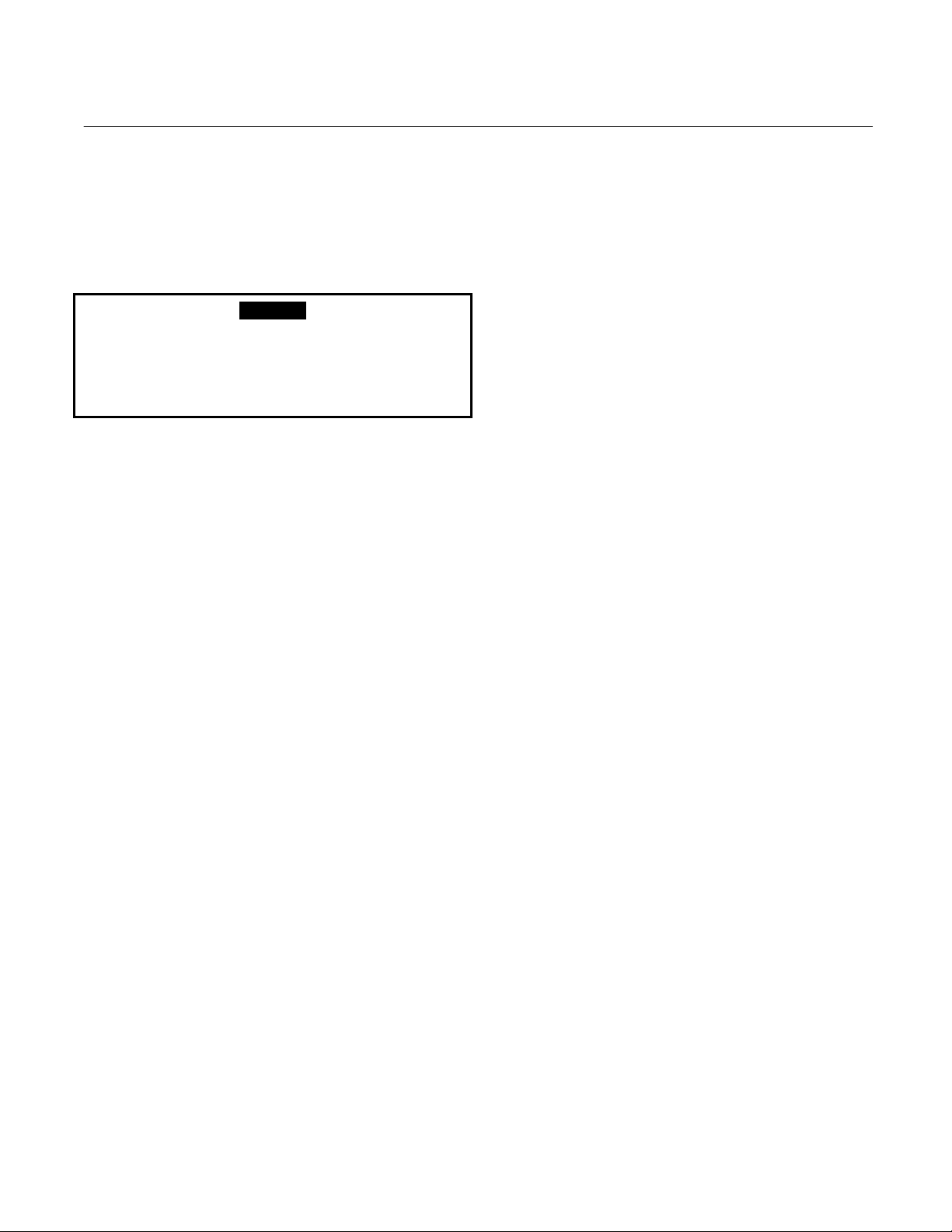
Model NGA2000 NDIR
MAINTENANCE AND TROUBLESHOOTING
DANGER
ELECTRICAL SHOCK HAZARD
Instruction Manual
748332-F
April 2003
SECTION 4
balance adjustments. These are factory-set,
and should be adjusted only in the following
cases:
Servicing requires access to live parts which can
cause death or serious injury. Refer servicing to
qualified personnel.
4-1 OVERVIEW
NDIR Analyzer Module components that may
require cleaning or replacement include:
• all printed circuit boards
• power fuse
• the module fan
• the chopper motor
• the source
• the detector
• flow sensor
• case temperature sensor
if the operator has changed sources, oscillator
board or detector
if the operator disassembles the bench to any
degree.
Also available for maintenance adjustment
through the Front Panel display and keypad
are the source current, preamplifier gain
(referred to as Signal Gain on the sub-menu)
and the modulation check.
4-2 PCB REPLACEMENT
Refer to Figure 4-1 on page 4-2 for locations
of the Signal, Micro, Power Supply, Oscillator
and optional Pressure Compensation boards.
All PCBs, except the Oscillator Board and the
LON Power Board, are secured to a side of
the analyzer module that folds out while
interconnect wiring is still in place. Remove
the securing screws and fold out the entire
panel.
• Analysis cells and optical components
• RTD - detector temp. controller
• thermal fuse
The only components that may require
adjustment are the oscillator tune and shutter
Rosemount Analytical Inc. A Division of Emerson Process Management Maintenance and Troubleshooting 4-1
To remove a particular board on the fold-out
panel, label and unplug all interconnect wiring,
and remove securing hardware. (See to
Figure 4-1 on page 4-2.) Do the reverse to
install a new board. Use caution when
installing connectors by observing correct
position (polarity) and alignment of pins.
Page 42

Instruction Manual
748332-F
April 2003
TOP VIEW
POWER SUPPLY
BOARD
SIDE VIEW
Model NGA2000 NDIR
PRESSURE
COMPENSATION
BOARD
Figure 4-1. Printed Circuit Board Fold-Out Panel Views
MICRO BOARD
SIGNAL
BOARD
4-3 POWER FUSE REPLACEMENT
Remove power to the Analyzer Module prior to
fuse replacement. To replace the Power Fuse,
view the front panel of the Analyzer Module, as
shown in Figure 4-2 below, and push and turn
the fuseholder cap 1/4 turn counterclockwise.
Remove and replace the fuse as required.
FRONT PANEL
FUSE
Figure 4-2. Power Fuse Location
4-2 Maintenance and Troubleshooting Rosemount Analytical Inc. A Division of Emerson Process Management
Page 43

Model NGA2000 NDIR
4-4 MODULE FAN REPLACEMENT
The Analyzer Module fan assembly is
disassembled as shown in Figure 4-3 below.
AIR FLOW
Instruction Manual
748332-F
April 2003
Before doing so, the entire optical bench must
be removed. See Figure 4-5on page 4-5.
Figure 4-3. Fan Assembly
Rosemount Analytical Inc. A Division of Emerson Process Management Maintenance and Troubleshooting 4-3
Page 44
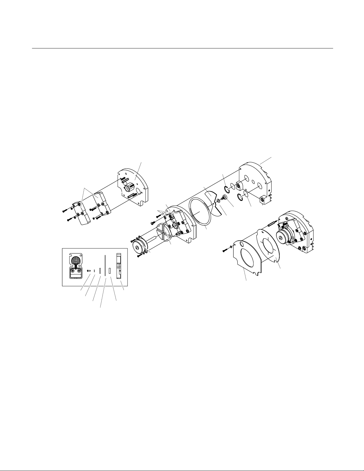
Instruction Manual
748332-F
April 2003
Model NGA2000 NDIR
4-5 CHOPPER MOTOR REPLACEMENT
See Figure 4-4 below for a exploded view of the
Motor/Source Assembly. The entire optical
bench must be removed to perform this
replacement.
Housing Assembly
Source Assemblies
(see detail below)
Ref - Source
Assemblies
Screw
Lock Washer
Insulator
Source Case
Insulator
Source
Ref - Housing
Assembly
Motor Plate
Motor
4-6 SOURCE REPLACEMENT
See Figure 4-4 below for a exploded view of
the Motor/Source Assembly. The entire optical
bench must be removed to perform this
replacement.
Dual Cap Assembly
Retaining
Ring
Chopper
Blade
Screen Filter
Screw
Nylon
Washer
O-Ring
Source Buffer
(optional)
Source Gasket
Figure 4-4. Motor/Source Assembly
4-4 Maintenance and Troubleshooting Rosemount Analytical Inc. A Division of Emerson Process Management
Page 45
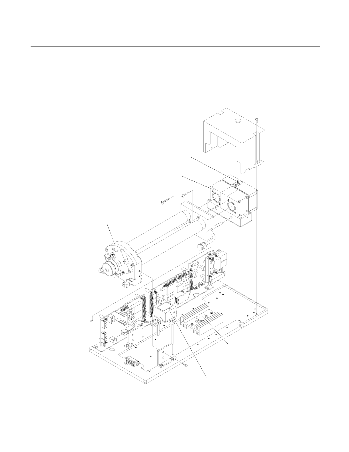
Model NGA2000 NDIR
4-7 DETECTOR REMOVAL
See Figure 4-5 below and Figure 4-8 on page
4-9 for breakdowns of the optical bench. The
entire optical bench
Motor/Source
Assembly
Detector Assembly
Instruction Manual
748332-F
April 2003
must be removed in order to perform this
disassembly.
Oscillator Tune
Adjust
Power
Transistor/Heatsink
Flow Sensor
Figure 4-5. Cell, PCB Assembly – Exploded View
Rosemount Analytical Inc. A Division of Emerson Process Management Maintenance and Troubleshooting 4-5
Page 46

Instruction Manual
748332-F
April 2003
4-8 FLOW SENSOR REPLACEMENT
See Figure 4-5 on page 4-5 for Flow Sensor
location. To replace Flow Sensor, remove all
connecting hardware and undo connections to
the sample line.
4-9 CASE TEMPERATURE SENSOR
REPLACEMENT
Case Temperature Sensor is attached to the
motor source assembly. To replace this
sensor, cut the Ty-Rap binder and disconnect
the sensor connector. Reverse these
instructions by reconnecting the new sensor
and attaching with a new Ty-Rap.
Model NGA2000 NDIR
Open Analyzer Module front panel
Access the oscillator tune value in the Primary
Variable Parameters menu.
Adjust oscillator tune knob to its maximum
setting and then turn it counterclockwise to 80
% of that maximum setting.
Access the detector signal value in the
Modulation Check
Flow zero gas (nitrogen) through the sample
cell until the display reading stabilizes.
DELICATE COMPONENTS
menu.
CAUTION
4-10 THERMAL FUSE REPLACEMENT
Disassemble and reassemble the Detector
block according to Figure 4-7 on page 4-7 to
replace the Detector Thermal Fuse.
4-11 OSCILLATOR TUNE/SOURCE BALANCE
SHUTTER ADJUSTMENT
The Analyzer Module is calibrated, tuned and
balanced at the factory. If the diagnostic
values for oscillator tune and detector signals
are within ±5 % of the factory settings in
Primary Variable Parameters
Check menus), no adjustment is necessary. If
not, see Figure 4-5 on page 4-5 and Figure
4-6 on page 4-7 for Oscillator Tune and
Source Balance Shutter adjustments, and do
the following:
Open Platform front panel, if present.
CAUTION
HAND INJURY HAZARD
and Modulation
The shutter is a delicate component with
only a six-degree rotation. Take care when
making the required adjustments.
Using an appropriate screwdriver that will fit
through the Source Balance Adjustment
Screw Holes (see Figure 4-5 on page 4-5),
rotate the sample shutter adjust screw until a
minimum reading on the display is obtained.
(A typical reading is 0.2 through 0.5.)
Add 0.5 V to the value obtained in Step 7 by
adjusting the sample shutter adjust screw
clockwise. (If this reading exceeds 1.2 V, then
a cell cleaning is necessary; see Section 4-12
on page 4-8.)
Rotate the shutter adjust screw clockwise until
the display reads the value obtained in Step 8.
Reassemble the Analyzer Module and, if
appropriate, the Platform.
Do not place hands or fingers in Platform
front handles when the front panel is open.
Dropping front panel while hand or fingers
are inside either handle can cause serious
injury.
4-6 Maintenance and Troubleshooting Rosemount Analytical Inc. A Division of Emerson Process Management
Page 47
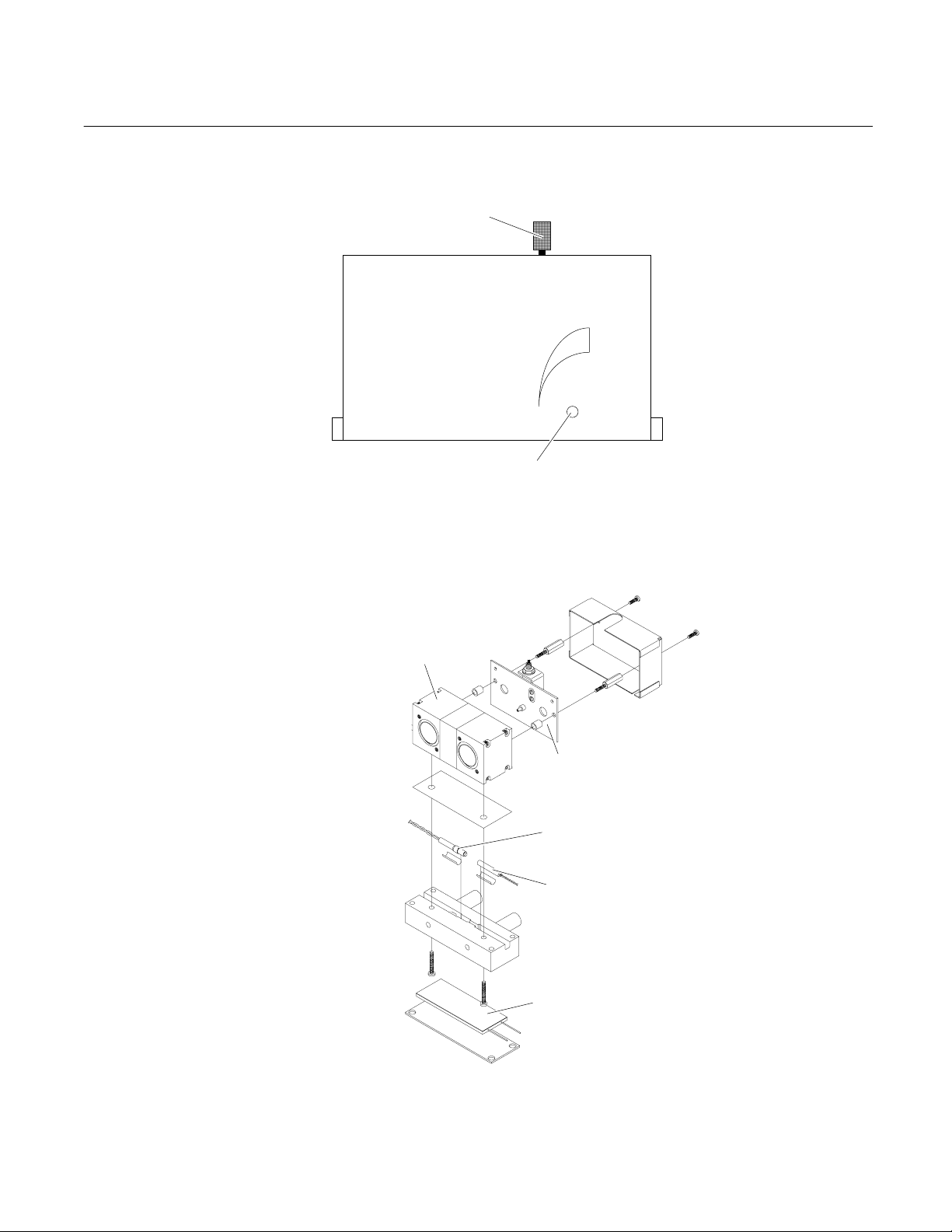
Model NGA2000 NDIR
Instruction Manual
748332-F
April 2003
DETECTOR ASSEMBLY COVER
(Front View)
Oscillator Tune Adjustment
SHUTTER
Sample
OPEN
CLOSE
Source Balance Shutter
Adjustment Screw Hole
Figure 4-6. Oscillator Tune, Source Balance Shutter Adjustments
Detector
Oscillator Board
Resistive Temperature
Detector
Thermal Fuse
Detector Heater
Figure 4-7. Detector Block (Exploded View)
Rosemount Analytical Inc. A Division of Emerson Process Management Maintenance and Troubleshooting 4-7
Page 48

Instruction Manual
748332-F
April 2003
4-12 CLEANING CELLS
When zero gas is introduced in the SAMPLE IN
inlet and the Detector signal is greater 1.2V, the
cells and windows require cleaning. To do this,
follow this procedure:
See Figure 4-8 on page 4-9 to identify which
detail drawing best matches the configuration in
question.
Fold out the PCB panel.
Disassemble the optical bench according to
Figure 4-5 on page 4-5 and the cells according to
Figure 4-8 on page 4-9.
Model NGA2000 NDIR
Inspect the cell inside by holding it up to a
bright light. If particles are seen, repeat Steps
5 and 6 as often as necessary.
After cleaning cell, examine O-rings at the
source, detector and end caps. If damaged,
replace with new O-rings.
Remove any contaminants from windows with
a lint-free cloth soaked in acetone. Do not use
alcohol or other solvents. Allow to air dry.
Reverse disassemble instructions to
reassemble the unit.
Perform a leak check.
Rinse the cell with acetone. If this does not
remove all foreign matter, use a soft brush. Do
not use any metallic object inside the cell
because it will scratch the gold plating. Loss of
gold plating may require cell replacement.
After all matter has been removed, rinse the cell
with distilled water and allow to air dry. Do not
use towels.
Replace desiccant if required. (See Section
4-13 on page 4-10.)
After cleaning cells, the Analyzer Module must
be optically aligned if the diagnostic values for
oscillator tune and detector signals are not
within ±5% of the factory settings. If they are
not within that range, follow Steps 7 through
10 of Section 4-11 on page 4-6.
4-8 Maintenance and Troubleshooting Rosemount Analytical Inc. A Division of Emerson Process Management
Page 49

Model NGA2000 NDIR
Instruction Manual
748332-F
April 2003
SHORT PATH CELLS
4mm TO 2.5 INCHES
Detector
Assembly
Desiccant Holder
Spacer
Shutter Block
Assembly
Desiccant
Holders
Sample Cell
Motor/Source
Assembly
Detector
Assembly
LONG PATH CELLS
Sample Cell
Shutter Block
Assembly
Motor/Source
Assembly
Figure 4-8. Cell Assembly
Rosemount Analytical Inc. A Division of Emerson Process Management Maintenance and Troubleshooting 4-9
Page 50

Instruction Manual
748332-F
April 2003
4-13 CELL DESICCANT
The reference cell may use a flowing
reference. If so, desiccant is required. A
desiccant holder is used on the inlet and
GAS DESICCANT PART NUMBER
CO2 Cardoxide 096218
CO Mg (C104)2 096217
H20 Mg (C104)2 096217
SOS Mg (C104)2 096217
CH4 Mg (C104)2 096217
Hexane Mg (C104)2 096217
CO + CO2 Cardoxide + Mg (C104)2 096217/096218
Model NGA2000 NDIR
outlets to keep moisture from entering the
reference cell (see Figure 4-7 on page 4-7).
The desiccant should be replaced each time
the cell is opened, refer to Table 4-1 below.
Before inserting desiccant, purge cell with dry
inert gas (i.e., N
2).
Table 4-1. Cell Desiccant
4-10 Maintenance and Troubleshooting Rosemount Analytical Inc. A Division of Emerson Process Management
Page 51

Model NGA2000 NDIR
4-14 MODULATION CHECK
The modulation check is a measure of the
energy absorption capacity of a gas mixture,
where total absorbency is 100% modulation
and zero absorbency is 0% modulation. The
modulation check can be used as a tool for
tracking the sensitivity of the Analyzer Module
and for discovering potential detector/source
problems.
To perform a modulation check, do the
following:
Access the Primary Variable Parameters
menu.
Select Modulation Check.
Follow the Instructions and Then line
commands, which are the following:
Flow zero gas, press START softkey and wait.
Instruction Manual
748332-F
April 2003
Flow span gas when prompted, press START
softkey and wait.
When the Instructions line again prompts the
user to flow zero gas, the modulation check is
finished.
Note the value on the Percent Modulation line.
Find the Percent Modulation value on the
Data Sheet in the rear of this manual. Some
standard Analyzer Modules will not have a
value. If a value is present, compare this to
the new value.
If 100% span gas was used during the
modulation check, the new value should be
within ±10% of value on the Data Sheet. If it is
out of this range, call the factory for further
interpretation. If modulation checks are used
for trending, variance from check to check
should not exceed ±20% per month.
Rosemount Analytical Inc. A Division of Emerson Process Management Maintenance and Troubleshooting 4-11
Page 52

Instruction Manual
748332-F
April 2003
Model NGA2000 NDIR
4-12 Maintenance and Troubleshooting Rosemount Analytical Inc. A Division of Emerson Process Management
Page 53

Instruction Manual
748332-F
Model NGA2000 NDIR
April 2003
SECTION 5
REPLACEMENT PARTS
WARNING
PARTS INTEGRITY
Tampering with or unauthorized substitution of components may adversely affect safety of this product.
Use only factory-approved components for repair.
To identify the configuration of an analyzer,
5-1 MATRIX
Each analyzer is configured per the customer
sales order. Below is the NDIR sales mat rix
which lists the various configurations
available.
locate the analyzer name-rating plate. The
12-position sales matrix identifier number
appears on the analyzer name-rating plate..
NDIR SINGLE CHANNEL INFRARED MEASUREMENT (ANALYZER MODULE)
01 Current Version Software
02 2.2.4 Version Software
03 3X Version Software - specify version
09, 10, 12, 20, 22, 23, 29, 30, 36, 38
[06], 07, 08, 11, 21, [24], 26, 76, 63
[16], [28], 19, [25], [27], 31, [37], 39, 41, [44]
[14], [15], [46], 54, 64, 65, [66], 67, 73
[56], 74, [75], 83, 84, [85], 88
99 SPECIAL
01 Four Standard Ranges
R1 One Non-Standard Range
R2 Two Non-Standard Ranges
R3 Three Non-Standard Ranges
R4 Four Non-Standard Ranges
99 Special
Code Software Version
Code
Configuration Identifier
[ ] Configurations utilize EXTENDED housings.
Code Linearized Non-Standard Range Selection
01 Standard (No Flow Sensor)
02 400 - 2000 cc/min
99 Special
NDIR 01 10 R1 01 Example
Rosemount Analytical Inc. A Division of Emerson Process Management Replacement Parts 5-1
Code Flow Path
Page 54

Instruction Manual
748332-F
April 2003
5-2 REPLACEMENT PARTS
While the following sections list parts which
are common to all NDIR Analyzer Modules,
the configuration number is required when
ordering parts which are specific to an
individual application. The configuration
number is on the Data Sheet in the rear of this
manual.
Model NGA2000 NDIR
623998 Oscillator Board
657466 LON/Power Board
655729 Detector Heater
622917 Temperature Sensor, Detector
898733 Thermal Fuse with Q Pad
902931 Flow Sensor
655943 Case Temperature Sensor
655630 Power Supply Board
655670 Pressure Compensation Board
658350 Computer Analysis Board
655610 Signal Board
655893 Fan
655891 Chopper Motor
655925 Source (Matched Pair)
5-2 Replacement Parts Rosemount Analytical Inc. A Division of Emerson Process Management
Page 55

Model NGA2000 NDIR
RETURN OF MATERIAL
6-1 RETURN OF MATERIAL
If factory repair of defective equipment is
required, proceed as follows:
1. Secure a return authorization from a
Rosemount Analytical Inc. Sales Office or
Representative before returning the
equipment. Equipment must be returned
with complete identification in accordance
with Rosemount instructions or it will not
be accepted.
Rosemount CSC will provide the shipping
address for your instrument.
In no event will Rosemount be
responsible for equipment returned
without proper authorization and
identification.
2. Carefully pack the defective unit in a
sturdy box with sufficient shock absorbing
material to ensure no additional damage
occurs during shipping.
3. In a cover letter, describe completely:
• The symptoms that determined the
equipment is faulty.
• The environment in which the
equipment was operating (housing,
weather, vibration, dust, etc.).
• Site from where the equipment was
removed.
• Whether warranty or non-warranty
service is expected.
• Complete shipping instructions for the
return of the equipment.
4. Enclose a cover letter and purchase order
and ship the defective equipment
according to instructions provided in the
Rosemount Return Authorization, prepaid,
to the address provided by Rosemount
CSC.
Rosemount Analytical Inc.
Process Analytical Division
Customer Service Center
1-800-433-6076
Instruction Manual
748332-F
April 2003
SECTION 6
If warranty service is expected, the defective
unit will be carefully inspected and tested at
the factory. If the failure was due to the
conditions listed in the standard Rosemount
warranty, the defective unit will be repaired or
replaced at Rosemount’s option, and an
operating unit will be returned to the customer
in accordance with the shipping instructions
furnished in the cover letter.
For equipment no longer under warranty, the
equipment will be repaired at the factory and
returned as directed by the purchase order
and shipping instructions.
6-2 CUSTOMER SERVICE
For order administration, replacement Parts,
application assistance, on-site or factory
repair, service or maintenance contract
information, contact:
Rosemount Analytical Inc.
Process Analytical Division
Customer Service Center
1-800-433-6076
6-3 TRAINING
A comprehensive Factory Training Program of
operator and service classes is available. For
a copy of the Current Operator and Service
Training Schedule contact the Technical
Services Department at:
Rosemount Analytical Inc.
Customer Service Center
1-800-433-6076
Rosemount Analytical Inc. A Division of Emerson Process Management Return of Material 6-1
Page 56

Instruction Manual
748332-F
April 2003
Model NGA2000 NDIR
6-2 Return of Material Rosemount Analytical Inc. A Division of Emerson Process Management
Page 57

Model NGA2000 NDIR
A
Analyzer Module
applying power, 3-1
calibration procedure, 3-4
function, 1-1
installation into Platform, 2-1
installation location, 2-2
more that one in system, 3-1
operating temperature, 2-2
unable to calibrate, 3-4
Instruction Manual
748332-F
April 2003
SECTION 7
INDEX
linear mode, 3-6
linearization coefficients
calculating, 3-6
linearizer, 1-1
Luft principle, 1-2
M
Maximum permissible interval between calibrations,
3-8
maximum range
changing, 3-8
B
binding, 3-2
C
Calibration
failure. See
calibration gas, 2-2
cells
high pressure, 1-3
connections
electrical, 2-4
inlet/outlet, 2-2
network, 2-4
power, 2-4
D
daisy chaining, 2-4
detector signal, 3-2
F
for non-standard fullscale ranges
linearization coefficients, 3-6
I
I/O Module
installation, 2-1
initial startup, 3-2
N
non-linear mode, 3-6
P
purge kit, 1-3
R
Readout accuracy
barometric pressure, 3-8
Return Authorization, 6-1
S
sample
dewpoint, 1-3, 2-2
excessive flow rate, 2-2
flow rate, 2-2
pressure, 1-3
pressure/filtration, 2-2
temperature, 1-3
shipping damage, 2-1
T
tune signal, 3-2
W
warm-up perio, 3-2
L
leak test, 2-2
Rosemount Analytical Inc. A Division of Emerson Process Management Index 7-1
Page 58

Instruction Manual
748332-F
April 2003
Model NGA2000 NDIR
7-2 Index Rosemount Analytical Inc. A Division of Emerson Process Management
Page 59

WARRANTY
Goods and part(s) (excluding consumables) manufactured by Seller are warranted to be free from
defects in workmanship and material under normal use and service for a period of twelve (12)
months from the date of shipment by Seller. Consumables, glass electrodes, membranes, liquid
junctions, electrolyte, o-rings, etc., are warranted to be free from defects in workmanship and material under normal use and service for a period of ninety (90) days from date of shipment by
Seller. Goods, part(s) and consumables proven by Seller to be defective in workmanship and/or
material shall be replaced or repaired, free of charge, F.O.B. Seller's factory provided that the
goods, part(s) or consumables are returned to Seller's designated factory, transportation charges
prepaid, within the twelve (12) month period of warranty in the case of goods and part(s), and in
the case of consumables, within the ninety (90) day period of warranty. This warranty shall be in
effect for replacement or repaired goods, part(s) and the remaining portion of the ninety (90) day
warranty in the case of consumables. A defect in goods, part(s) and consumables of the commercial unit shall not operate to condemn such commercial unit when such goods, part(s) and
consumables are capable of being renewed, repaired or replaced.
The Seller shall not be liable to the Buyer, or to any other person, for the loss or damage directly
or indirectly, arising from the use of the equipment or goods, from breach of any warranty, or from
any other cause. All other warranties, expressed or implied are hereby excluded.
IN CONSIDERATION OF THE HEREIN STATED PURCHASE PRICE OF THE GOODS,
SELLER GRANTS ONLY THE ABOVE STATED EXPRESS WARRANTY. NO OTHER WARRANTIES ARE GRANTED INCLUDING, BUT NOT LIMITED TO, EXPRESS AND IMPLIED
WARRANTIES OR MERCHANTABILITY AND FITNESS FOR A PARTICULAR PURPOSE.
Limitations of Remedy.
LAY IN PERFORMANCE. THE SOLE AND EXCLUSIVE REMEDY FOR BREACH OF WARRANTY SHALL BE LIMITED TO REPAIR OR REPLACEMENT UNDER THE STANDARD
WARRANTY CLAUSE. IN NO CASE, REGARDLESS OF THE FORM OF THE CAUSE OF ACTION, SHALL SELLER'S LIABILITY EXCEED THE PRICE TO BUYER OF THE SPECIFIC
GOODS MANUFACTURED BY SELLER GIVING RISE TO THE CAUSE OF ACTION. BUYER
AGREES THAT IN NO EVENT SHALL SELLER'S LIABILITY EXTEND TO INCLUDE INCIDENTAL OR CONSEQUENTIAL DAMAGES. CONSEQUENTIAL DAMAGES SHALL INCLUDE, BUT
ARE NOT LIMITED TO, LOSS OF ANTICIPATED PROFITS, LOSS OF USE, LOSS OF REVENUE, COST OF CAPITAL AND DAMAGE OR LOSS OF OTHER PROPERTY OR EQUIPMENT.
IN NO EVENT SHALL SELLER BE OBLIGATED TO INDEMNIFY BUYER IN ANY MANNER
NOR SHALL SELLER BE LIABLE FOR PROPERTY DAMAGE AND/OR THIRD PARTY CLAIMS
COVERED BY UMBRELLA INSURANCE AND/OR INDEMNITY COVERAGE PROVIDED TO
BUYER, ITS ASSIGNS, AND EACH SUCCESSOR INTEREST TO THE GOODS PROVIDED
HEREUNDER.
Force Majeure.
Seller's direct control.
Seller shall not be liable for failure to perform due to labor strikes or acts beyond
SELLER SHALL NOT BE LIABLE FOR DAMAGES CAUSED BY DE-
Page 60

Instruction Manual
A
748332-F
April 2003
Model NGA2000 NDIR
EMERSON PROCESS MAN
Rosemount Analytical Inc.
Process Analytic Division
1201 N. Main St.
Orrville, OH 44667-0901
T (330) 682-9010
F (330) 684-4434
E gas.csc@emersonprocess.com
ASIA - PACIFIC
Fisher-Rosemount
Singapore Private Ltd.
1 Pandan Crescent
Singapore 128461
Republic of Singapore
T 65-777-8211
F 65-777-0947
http://www.processanalytic.com
© Rosemount Analytical Inc. 2003
GEMENT
EUROPEAN TECHNOLOGY CENTER
Fisher-Rosemount GmbH & Co.
Industriestrasse 1
63594 Hasselroth
Germany
T 49-6055-884 0
F 49-6055-884209
EUROPE, MIDDLE EAST, AFRICA
Fisher-Rosemount Ltd.
Heath Place
Bognor Regis
West Sussex PO22 9SH
England
T 44-1243-863121
F 44-1243-845354
LATIN AMERICA
Fisher - Rosemount
Av. das Americas
3333 sala 1004
Rio de Janeiro, RJ
Brazil 22631-003
T 55-21-2431-1882
Page 61
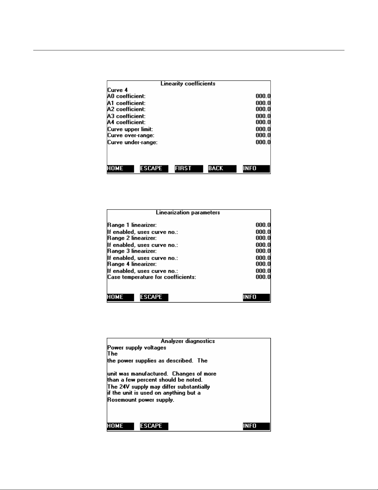
Model NGA2000 NDIR
Instruction Manual
748417-B
April 2003
Menu: 29 LINRANGE4
Menu: 30 LINRANGE0
Menu: 31 AMPWRI1
Rosemount Analytical Inc. A Division of Emerson Process Management Index 7-11
Page 62

Instruction Manual
748417-B
April 2003
Model NGA2000 NDIR
Menu: 32 FLOCHEK1I1
Menu: 33 FILTER
Menu: 34 AM1VI1
7-12 Return of Material Rosemount Analytical Inc. A Division of Emerson Process Management
Page 63

Model NGA2000 NDIR
Instruction Manual
748417-B
April 2003
Menu: 35 AMTEMPI1
Menu: 36 AM2VA
Menu: 37 PLIMITSA
Rosemount Analytical Inc. A Division of Emerson Process Management Index 7-13
Page 64

Instruction Manual
748417-B
April 2003
Model NGA2000 NDIR
Menu: 38 TLIMITSA
Menu: 39 AMMISCI1
Menu: 40 MODTEST
7-14 Return of Material Rosemount Analytical Inc. A Division of Emerson Process Management
Page 65

Model NGA2000 NDIR
Instruction Manual
748417-B
April 2003
Menu: 41 ANALSIMPLE
Menu: 42 FILTERI1
Menu: 43 LINRANGE0I1
Rosemount Analytical Inc. A Division of Emerson Process Management Index 7-15
Page 66
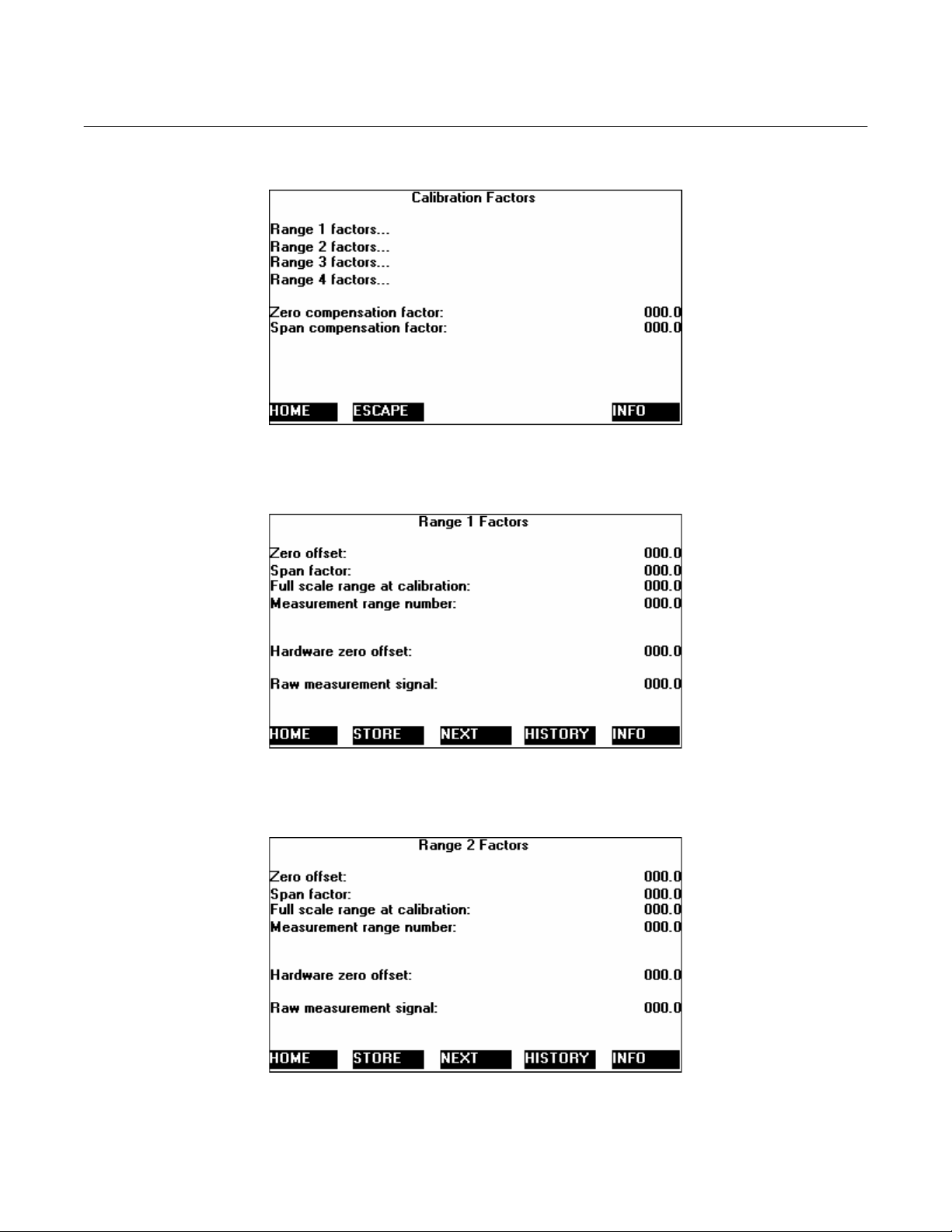
Instruction Manual
748417-B
April 2003
Model NGA2000 NDIR
Menu: 44 CALFACTORS
Menu: 45 R1FACTORS
Menu: 46 RN2FACTORS
7-16 Return of Material Rosemount Analytical Inc. A Division of Emerson Process Management
Page 67

Model NGA2000 NDIR
Instruction Manual
748417-B
April 2003
Menu: 47 RN3FACTORS
Menu: 48 RN4FACTORS
Menu: 49 AMHELPINDEX
Rosemount Analytical Inc. A Division of Emerson Process Management Index 7-17
Page 68

Instruction Manual
748417-B
April 2003
Model NGA2000 NDIR
Menu: 50 LINRANGE1I1
Menu: 51 AMTRENDI1
Menu: 52 CALFACTORSI1
7-18 Return of Material Rosemount Analytical Inc. A Division of Emerson Process Management
Page 69

Model NGA2000 NDIR
Instruction Manual
748417-B
April 2003
Menu: 53 APARLST2
Menu: 54 APARLST4
Menu: 55 APARLST5
Rosemount Analytical Inc. A Division of Emerson Process Management Index 7-19
Page 70

Instruction Manual
748417-B
April 2003
Model NGA2000 NDIR
Menu: 56 APARLST6
Menu: 57 LISTNOTES
Menu: 58 MPARMS2
7-20 Return of Material Rosemount Analytical Inc. A Division of Emerson Process Management
Page 71

Model NGA2000 NDIR
Instruction Manual
748417-B
April 2003
Menu: 59 DISPLAY
Menu: 60 ANALSET2
Menu: 61 ESCAPE_HELP
Rosemount Analytical Inc. A Division of Emerson Process Management Index 7-21
Page 72
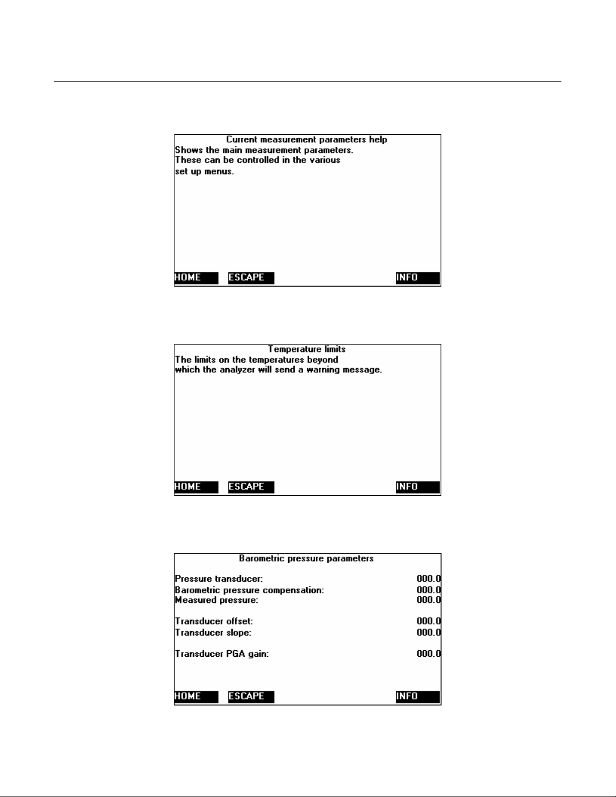
Instruction Manual
748417-B
April 2003
Model NGA2000 NDIR
Menu: 62 MPARMSI1
Menu: 63 TLIMITSIAI1
Menu: 64 BAROM_PARMS
7-22 Return of Material Rosemount Analytical Inc. A Division of Emerson Process Management
Page 73

Model NGA2000 NDIR
Instruction Manual
748417-B
April 2003
Menu: 65 ANALSETI2
Menu: 66 AMHELPINDEX2
Menu: 67 MODTESTI1
Rosemount Analytical Inc. A Division of Emerson Process Management Index 7-23
Page 74

Instruction Manual
748417-B
April 2003
Model NGA2000 NDIR
Menu: 68 BAROM_PARMI1
Menu: 69 SW_DIAG
Menu: 70 CALI1
7-24 Return of Material Rosemount Analytical Inc. A Division of Emerson Process Management
Page 75

Model NGA2000 NDIR
Instruction Manual
748417-B
April 2003
Menu: 71 AM1VHIST
Menu: 72 LINFUNCT
Menu: 73 POLYSETUP
Rosemount Analytical Inc. A Division of Emerson Process Management Index 7-25
Page 76
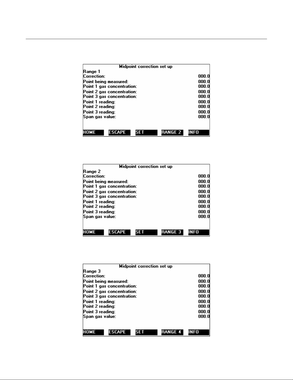
Instruction Manual
748417-B
April 2003
Model NGA2000 NDIR
Menu: 74 MIDPOINT1
Menu: 75 MIDPOINT2
Menu: 76 MIDPOINT3
7-26 Return of Material Rosemount Analytical Inc. A Division of Emerson Process Management
Page 77

Model NGA2000 NDIR
Instruction Manual
748417-B
April 2003
Menu: 77 MIDPOINT4
Menu: 78 POLYGAS1
Menu: 79 POLYGAS2
Rosemount Analytical Inc. A Division of Emerson Process Management Index 7-27
Page 78

Instruction Manual
748417-B
April 2003
Model NGA2000 NDIR
Menu: 80 POLYGAS3
Menu: 81 POLYGAS4
Menu: 82 POLYGAS5
7-28 Return of Material Rosemount Analytical Inc. A Division of Emerson Process Management
Page 79

Model NGA2000 NDIR
Instruction Manual
748417-B
April 2003
Menu: 83 POLYGAS6
Menu: 84 POLYGAS7
Menu: 85 POLYGAS8
Rosemount Analytical Inc. A Division of Emerson Process Management Index 7-29
Page 80

Instruction Manual
748417-B
April 2003
Model NGA2000 NDIR
Menu: 86 POLYGAS9
Menu: 87 POLYGAS0
Menu: 88 EXP_CAL
7-30 Return of Material Rosemount Analytical Inc. A Division of Emerson Process Management
Page 81

Model NGA2000 NDIR
Instruction Manual
748417-B
April 2003
Menu: 89 ZEROI2
Menu: 90 EXP_CAL_DAT
Menu: 91 EXP_CAL_DATI
Rosemount Analytical Inc. A Division of Emerson Process Management Index 7-31
Page 82
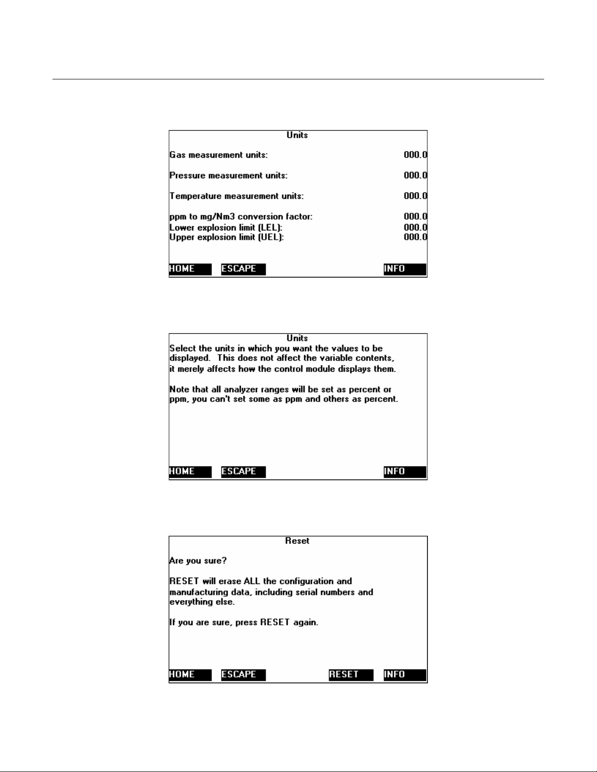
Instruction Manual
748417-B
April 2003
Model NGA2000 NDIR
Menu: 92 UNITS
Menu: 93 UNITSI1
Menu: 94 RESET
7-32 Return of Material Rosemount Analytical Inc. A Division of Emerson Process Management
Page 83

Model NGA2000 NDIR
Instruction Manual
748417-B
April 2003
Menu: 95 STORE
Menu: 96 RFHIST1A
Menu: 97 RFACTORSIA
Rosemount Analytical Inc. A Division of Emerson Process Management Index 7-33
Page 84

Instruction Manual
748417-B
April 2003
Model NGA2000 NDIR
Menu: 98 RFHIST2A
Menu: 99 RFHIST3A
Menu: 100 RFHIST4A
7-34 Return of Material Rosemount Analytical Inc. A Division of Emerson Process Management
Page 85

Model NGA2000 NDIR
Instruction Manual
748417-B
April 2003
Menu: 101 TWEAKI1
Menu: 102 INIT
Menu: 103 SW_DIAGI1
Rosemount Analytical Inc. A Division of Emerson Process Management Index 7-35
Page 86

Instruction Manual
748417-B
April 2003
Model NGA2000 NDIR
Menu: 104 STOREDPVA
Menu: 105 ZERO_NOW2
Menu: 106 SPAN_NOW2
7-36 Return of Material Rosemount Analytical Inc. A Division of Emerson Process Management
Page 87

Model NGA2000 NDIR
Instruction Manual
748417-B
April 2003
Menu: 107 POLYSETI1
Menu: 108 POLYSETI2
Menu: 109 POLYSETI3
Rosemount Analytical Inc. A Division of Emerson Process Management Index 7-37
Page 88

Instruction Manual
748417-B
April 2003
Model NGA2000 NDIR
Menu: 110 ANALSETI3
Menu: 111 MPARMS
Menu: 112 FLOWLIMITS
7-38 Return of Material Rosemount Analytical Inc. A Division of Emerson Process Management
Page 89

Model NGA2000 NDIR
Instruction Manual
748417-B
April 2003
Menu: 113 PLIMITSAI1
Menu: 114 ABOUT
Menu: 115 ABOUT1
Rosemount Analytical Inc. A Division of Emerson Process Management Index 7-39
Page 90

Instruction Manual
748417-B
April 2003
Model NGA2000 NDIR
Menu: 116 ALARM1
7-40 Return of Material Rosemount Analytical Inc. A Division of Emerson Process Management
Page 91

Model NGA2000 NDIR
A
Analyzer Module
applying power, 3-1
calibration procedure, 3-4
function, 1-1
installation into Platform, 2-1
installation location, 2-2
more that one in system, 3-1
operating temperature, 2-2
unable to calibrate, 3-4
Instruction Manual
748417-B
April 2003
SECTION 8
INDEX
linear mode, 3-6
linearization coefficients
calculating, 3-6
linearizer, 1-1
Luft principle, 1-2
M
Maximum permissible interval between calibrations,
3-8
maximum range
changing, 3-8
B
binding, 3-2
C
Calibration
failure. See
calibration gas, 2-2
cells
high pressure, 1-3
connections
electrical, 2-4
inlet/outlet, 2-2
network, 2-4
power, 2-4
D
daisy chaining, 2-4
detector signal, 3-2
F
for non-standard fullscale ranges
linearization coefficients, 3-6
I
I/O Module
installation, 2-1
initial startup, 3-2
N
non-linear mode, 3-6
P
purge kit, 1-3
R
Readout accuracy
barometric pressure, 3-8
Return Authorization, 6-1
S
sample
dewpoint, 1-3, 2-2
excessive flow rate, 2-2
flow rate, 2-2
pressure, 1-3
pressure/filtration, 2-2
temperature, 1-3
shipping damage, 2-1
T
tune signal, 3-2
W
warm-up perio, 3-2
L
leak test, 2-2
Rosemount Analytical Inc. A Division of Emerson Process Management Index 8-1
Page 92

Instruction Manual
748417-B
April 2003
Model NGA2000 NDIR
8-2 Index Rosemount Analytical Inc. A Division of Emerson Process Management
Page 93

Model NGA2000 PMD, NDIR
VAISALA BAROMETRIC PRESSURE TRANSDUCER
Addendum
748461-B
April 2003
This addendum serves as an amendment to
the Model NGA 2000 PMD and NDIR instruction manuals. The following information
should be considered part of the manual, if
your instrument has a Vaisala Barometric
Pressure Transducer installed in it, or if you
are retrofitting a PMD or NDIR with a Vaisala
transducer kit.
The Vaisala PTB100 series Analog Barometer
is a N.I.S.T. traceable precision silicon capacitive atmospheric pressure transducer. The
sensor delivers an analog voltage output that
is inversely proportional to its inlet pressure. It
has an operational ambient pressure range of
800 to 1060 hPa.
The original PMD and NDIR instruments were
designed for use with a resistance bridge type
of pressure transducer requiring an external
gain amplifier with an offset trim The Vaisala
transducer contains an integral gain amplifier
that is scaled for a 0 to +5 Vdc output. The
661380 “Interface Board” contains the circuitry to convert the Vaisala single ended 0 to
+5 V dc output into the referenced bridge 0 to
+0.625 V dc output configuration that is required by the Analyzer module’s Computer
Analysis Board. The Vaisala transducer kit is
backward compatible with the original Rosemount pressure transducer.
Vaisala Interface Board Circuit Function:
The Vaisala Interface Circuit board adapts the
single ended analog output of the Vaisala
sensor into a Precision Voltage referenced,
balanced bridge (at 1 atmosphere) input configuration. A “Bridge Balance” pot on the
Vaisala Interface Circuit board provides the
fine trim “Bridge Balancing” calibration adjustment that is required to set up each indi-
vidual transducer at a known ambient air
pressure. Test points are provided on the circuit board for this adjustment.
The Vaisala transducer output range is 0 to
+5 Vdc.
The Vaisala analog output voltage is inverted
and fed into a balanced summing node that is
referenced by a precision regulator. The
summing node voltage is 0.000 Vdc at 1013
hPa (1 atmosphere ambient air pressure). The
summing node voltage is then buffered, inverted, and gain reduced by a factor of 8 to
produce the Pressure Compensation Output
voltage at J12-1 for the Computer Analysis
board.
Low noise, Low input current offset Op-Amps,
and common substrate resistors are used to
reduce gain tracking errors and null thermal
coefficient effects.
1-1 INSTALLATION & RETROFIT
INSTRUCTIONS
1. Remove the original Rosemount transducer circuit board assembly, located on
the motherboard at J12 and J13 (if present).
2. Install the transducer with the pressure
inlet facing the rear of the instrument using the mounting studs provided on lefthand side of the detector housing.
3. Install the Interface board into it’s mating
sockets (J12 and J13) on the motherboard.
4. Connect the 4-pin cable (P1) from the interface board (noting pin polarity) to the
Vaisala Pressure Transducer.
http://www.processanalytic.com
Page 94

Addendum
748461-B
April 2003
5. Connect the instrument sample inlet tubing to the Vaisala Pressure Inlet port.
Model NGA2000 PMD, NDIR
Barometric Pressure menu reads the correct
ambient air pressure.
6. Enable the Barometric Pressure Compensation and the Use Local Reading options via the Expert Controls – Analyzer
Module Diagnostics – Barometric Pressure Compensation menus of the instrument. The instrument will automatically
detect and report the ‘Presence’ of the
Pressure Compensation Option.
1-2 ADJUSTMENT PROCEDURE
Circuit adjustment can be made using Barometric Pressure menu display, or an external
Digital voltmeter.
Display Method
With no sample inlet lines connected and the
instrument exhaust ported to atmosphere, adjust R1 on the 661380 Interface board until
the Barometric Pressure reading on the
DMM Method
Connect the DMM (+) to TP1 on the 661380
Interface board, (-) to TP2. Set the DMM to
measure mVDC. With no sample inlet lines
connected and the instrument exhaust ported
to atmosphere, adjust R1 on the Interface
board until the DMM reads 0.000 Vdc ± 0.001
V. The instrument is now calibrated at 1
ATM.
1-3 HIGH ALTITUDE VERSION OPTION
For applications where the instrument is to be
used above 5400 Feet (MSL) an alternate
transducer option is available from the factory.
This version consists of a Vaisala model
PTB100B transducer (900-1100 hPa range).
Please contact the factory if you require this
option.
2 of 2
Addendum – Vaisala Transducer Rosemount Analytical Inc. A Division of Emerson Process Management
Page 95

WARRANTY
Goods and part(s) (excluding consumables) manufactured by Seller are warranted to be free from
defects in workmanship and material under normal use and service for a period of twelve (12)
months from the date of shipment by Seller. Consumables, glass electrodes, membranes, liquid
junctions, electrolyte, o-rings, etc., are warranted to be free from defects in workmanship and material under normal use and service for a period of ninety (90) days from date of shipment by
Seller. Goods, part(s) and consumables proven by Seller to be defective in workmanship and/or
material shall be replaced or repaired, free of charge, F.O.B. Seller's factory provided that the
goods, part(s) or consumables are returned to Seller's designated factory, transportation charges
prepaid, within the twelve (12) month period of warranty in the case of goods and part(s), and in
the case of consumables, within the ninety (90) day period of warranty. This warranty shall be in
effect for replacement or repaired goods, part(s) and the remaining portion of the ninety (90) day
warranty in the case of consumables. A defect in goods, part(s) and consumables of the commercial unit shall not operate to condemn such commercial unit when such goods, part(s) and
consumables are capable of being renewed, repaired or replaced.
The Seller shall not be liable to the Buyer, or to any other person, for the loss or damage directly
or indirectly, arising from the use of the equipment or goods, from breach of any warranty, or from
any other cause. All other warranties, expressed or implied are hereby excluded.
IN CONSIDERATION OF THE HEREIN STATED PURCHASE PRICE OF THE GOODS,
SELLER GRANTS ONLY THE ABOVE STATED EXPRESS WARRANTY. NO OTHER WARRANTIES ARE GRANTED INCLUDING, BUT NOT LIMITED TO, EXPRESS AND IMPLIED
WARRANTIES OR MERCHANTABILITY AND FITNESS FOR A PARTICULAR PURPOSE.
Limitations of Remedy.
LAY IN PERFORMANCE. THE SOLE AND EXCLUSIVE REMEDY FOR BREACH OF WARRANTY SHALL BE LIMITED TO REPAIR OR REPLACEMENT UNDER THE STANDARD
WARRANTY CLAUSE. IN NO CASE, REGARDLESS OF THE FORM OF THE CAUSE OF ACTION, SHALL SELLER'S LIABILITY EXCEED THE PRICE TO BUYER OF THE SPECIFIC
GOODS MANUFACTURED BY SELLER GIVING RISE TO THE CAUSE OF ACTION. BUYER
AGREES THAT IN NO EVENT SHALL SELLER'S LIABILITY EXTEND TO INCLUDE INCIDENTAL OR CONSEQUENTIAL DAMAGES. CONSEQUENTIAL DAMAGES SHALL INCLUDE, BUT
ARE NOT LIMITED TO, LOSS OF ANTICIPATED PROFITS, LOSS OF USE, LOSS OF REVENUE, COST OF CAPITAL AND DAMAGE OR LOSS OF OTHER PROPERTY OR EQUIPMENT.
IN NO EVENT SHALL SELLER BE OBLIGATED TO INDEMNIFY BUYER IN ANY MANNER
NOR SHALL SELLER BE LIABLE FOR PROPERTY DAMAGE AND/OR THIRD PARTY CLAIMS
COVERED BY UMBRELLA INSURANCE AND/OR INDEMNITY COVERAGE PROVIDED TO
BUYER, ITS ASSIGNS, AND EACH SUCCESSOR INTEREST TO THE GOODS PROVIDED
HEREUNDER.
Force Majeure.
Seller's direct control.
Seller shall not be liable for failure to perform due to labor strikes or acts beyond
SELLER SHALL NOT BE LIABLE FOR DAMAGES CAUSED BY DE-
Page 96

Instruction Manual
A
748417-B
April 2003
Model NGA2000 NDIR
EMERSON PROCESS MAN
Rosemount Analytical Inc.
Process Analytic Division
1201 N. Main St.
Orrville, OH 44667-0901
T (330) 682-9010
F (330) 684-4434
E gas.csc@emersonprocess.com
ASIA - PACIFIC
Fisher-Rosemount
Singapore Private Ltd.
1 Pandan Crescent
Singapore 128461
Republic of Singapore
T 65-777-8211
F 65-777-0947
http://www.processanalytic.com
© Rosemount Analytical Inc. 2003
GEMENT
EUROPEAN TECHNOLOGY CENTER
Fisher-Rosemount GmbH & Co.
Industriestrasse 1
63594 Hasselroth
Germany
T 49-6055-884 0
F 49-6055-884209
EUROPE, MIDDLE EAST, AFRICA
Fisher-Rosemount Ltd.
Heath Place
Bognor Regis
West Sussex PO22 9SH
England
T 44-1243-863121
F 44-1243-845354
LATIN AMERICA
Fisher - Rosemount
Av. das Americas
3333 sala 1004
Rio de Janeiro, RJ
Brazil 22631-003
T 55-21-2431-1882
 Loading...