

Page 1

MON2000
Software for Gas Chromatographs
User Manual
Applies to Both:
Daniel Danalyzer On-Line Gas Chromatographs
Rosemount Analytical Process Gas Chromatographs
Part Number 3-9000-522
Revision R
JULY 2010
Page 2

Page 3

MON2000 Software for Gas Chromatographs
Manual
NOTICE
DANIEL MEASUREMENT AND CONTROL, INC. AND ROSEMOUNT ANALYTICAL
(COLLECTIVELY, “SELLER”) SHALL NOT BE LIABLE FOR TECHNICAL OR EDITORIAL ERRORS IN
THIS MANUAL OR OMISSIONS FROM THIS MANUAL. SELLER MAKES NO WARRANTIES,
EXPRESSED OR IMPLIED, INCLUDING THE IMPLIED WARRANTIES OF MERCHANTABILITY AND
FITNESS FOR A PARTICULAR PURPOSE WITH RESPECT TO THIS MANUAL AND, IN NO EVENT,
SHALL SELLER BE LIABLE FOR ANY SPECIAL OR CONSEQUENTIAL DAMAGES INCLUDING,
BUT NOT LIMITED TO, LOSS OF PRODUCTION, LOSS OF PROFITS, ETC.
PRODUCT NAMES USED HEREIN ARE FOR MANUFACTURER OR SUPPLIER IDENTIFICATION
ONLY AND MAY BE TRADEMARKS/REGISTERED TRADEMARKS OF THESE COMPANIES.
THE CONTENTS OF THIS PUBLICATION ARE PRESENTED FOR INFORMATIONAL PURPOSES
ONLY, AND WHILE EVERY EFFORT HAS BEEN MADE TO ENSURE THEIR ACCURACY, THEY
ARE NOT TO BE CONSTRUED AS WARRANTIES OR GUARANTEES, EXPRESSED OR IMPLIED,
REGARDING THE PRODUCTS OR SERVICES DESCRIBED HEREIN OR THEIR USE OR
APPLICABILITY. WE RESERVE THE RIGHT TO MODIFY OR IMPROVE THE DESIGNS OR
SPECIFICATIONS OF SUCH PRODUCTS AT ANY TIME.
SELLER DOES NOT ASSUME RESPONSIBILITY FOR THE SELECTION, USE OR MAINTENANCE
OF ANY PRODUCT. RESPONSIBILITY FOR PROPER SELECTION, USE AND MAINTENANCE OF
ANY SELLER PRODUCT REMAINS SOLELY WITH THE PURCHASER AND END-USER.
DANIEL AND THE DANIEL LOGO ARE REGISTERED TRADEMARKS OF DANIEL MEASUREMENT
AND CONTROL, INC. ROSEMOUNT AND THE ROSEMOUNT ANALYTICAL LOGO ARE
REGISTERED TRADEMARKS OF ROSEMOUNT ANALYTICAL. THE EMERSON LOGO IS A
TRADEMARK AND SERVICE MARK OF EMERSON ELECTRIC CO.
COPYRIGHT
U.S.A.
All rights reserved. No part of this work may be reproduced or copied in any form or by any
means - graphic, electronic, or mechanical — without first receiving the written permission of
Daniel Measurement and Control, Inc. Houston, Texas, U.S.A.
©
2010 BY DANIEL MEASUREMENT AND CONTROL, INC., HOUSTON, TEXAS,
Page 4

WARRANTY
1. LIMITED WARRANTY: Subject to the limitations contained in Section 2 herein and except as
otherwise expressly provided herein, Daniel Measurement and Control, Inc. and Rosemount
Analytical, (collectively“Seller”) warrants that the firmware will execute the programming
instructions provided by Seller, and that the Goods manufactured or Services provided by Seller
will be free from defects in materials or workmanship under normal use and care until the
expiration of the applicable warranty period. Goods are warranted for twelve (12) months from
the date of initial installation or eighteen (18) months from the date of shipment by Seller,
whichever period expires first. Consumables and Services are warranted for a period of 90 days
from the date of shipment or completion of the Services. Products purchased by Seller from a
third party for resale to Buyer ("Resale Products") shall carry only the warranty extended by the
original manufacturer. Buyer agrees that Seller has no liability for Resale Products beyond making
a reasonable commercial effort to arrange for procurement and shipping of the Resale Products. If
Buyer discovers any warranty defects and notifies Seller thereof in writing during the applicable
warranty period, Seller shall, at its option, promptly correct any errors that are found by Seller in
the firmware or Services, or repair or replace F.O.B. point of manufacture that portion of the
Goods or firmware found by Seller to be defective, or refund the purchase price of the defective
portion of the Goods/Services. All replacements or repairs necessitated by inadequate
maintenance, normal wear and usage, unsuitable power sources, unsuitable environmental
conditions, accident, misuse, improper installation, modification, repair, storage or handling, or
any other cause not the fault of Seller are not covered by this limited warranty, and shall be at
Buyer's expense. Seller shall not be obligated to pay any costs or charges incurred by Buyer or
any other party except as may be agreed upon in writing in advance by an authorized Seller representative. All costs of dismantling, reinstallation and freight and the time and expenses of
Seller's personnel for site travel and diagnosis under this warranty clause shall be borne by Buyer
unless accepted in writing by Seller. Goods repaired and parts replaced during the warranty
period shall be in warranty for the remainder of the original warranty period or ninety (90) days,
whichever is longer. This limited warranty is the only warranty made by Seller and can be
amended only in a writing signed by an authorized representative of Seller. Except as otherwise
expressly provided in the Agreement, THERE ARE NO REPRESENTATIONS OR WARRANTIES OF
ANY KIND, EXPRESSED OR IMPLIED, AS TO MERCHANTABILITY, FITNESS FOR PARTICULAR
PURPOSE, OR ANY OTHER MATTER WITH RESPECT TO ANY OF THE GOODS OR SERVICES. It
is understood that corrosion or erosion of materials is not covered by our guarantee.
2.
LIMITATION OF REMEDY AND LIABILITY: SELLER SHALL NOT BE LIABLE FOR DAMAGES
CAUSED BY DELAY IN PERFORMANCE. THE SOLE AND EXCLUSIVE REMEDY FOR BREACH OF
WARRANTY HEREUNDER SHALL BE LIMITED TO REPAIR, CORRECTION, REPLACEMENT OR
REFUND OF PURCHASE PRICE UNDER THE LIMITED WARRANTY CLAUSE IN SECTION 1
HEREIN. IN NO EVENT, REGARDLESS OF THE FORM OF THE CLAIM OR CAUSE OF ACTION
(WHETHER BASED IN CONTRACT, INFRINGEMENT, NEGLIGENCE, STRICT LIABILITY, OTHER
TORT OR OTHERWISE), SHALL SELLER'S LIABILITY TO BUYER AND/OR ITS CUSTOMERS
EXCEED THE PRICE TO BUYER OF THE SPECIFIC GOODS MANUFACTURED OR SERVICES
PROVIDED BY SELLER GIVING RISE TO THE CLAIM OR CAUSE OF ACTION. BUYER AGREES
THAT IN NO EVENT SHALL SELLER'S LIABILITY TO BUYER AND/OR ITS CUSTOMERS EXTEND
TO INCLUDE INCIDENTAL, CONSEQUENTIAL OR PUNITIVE DAMAGES. THE TERM
"CONSEQUENTIAL DAMAGES" SHALL INCLUDE, BUT NOT BE LIMITED TO, LOSS OF
ANTICIPATED PROFITS, LOSS OF USE, LOSS OF REVENUE AND COST OF CAPITAL.
Page 5

IMPORTANT INSTRUCTIONS
• Read all instructions prior to installing, operating, and servicing this product.
• Follow all warnings, cautions, and instructions marked on and supplied with this product.
• Inspect the equipment packing case and if damage exists, notify your local carrier for
liability.
• Open the packing list and carefully remove equipment and spare or replacement parts
from the case. Inspect all equipment for damage and missing parts.
• If items are damaged or missing, contact the manufacturer at 1 (713) 827-6314 for
instructions about receiving replacement parts.
• Install equipment as specified per the installation instructions and per applicable local and
national codes. All connections shall be made to proper electrical and pressure sources.
• Ensure that all equipment doors are closed and protective covers are in place, except
when maintenance is being performed by qualified persons, to prevent personal injury.
• Use of this product for any purpose other than its intended purpose may result in property
damage and/or serious injury or death.
• Before opening the flameproof enclosure in a flammable atmosphere, the electrical
circuits must be interrupted.
• Repairs must be performed using only authorized replacement parts as specified by the
manufacturer. Use of unauthorized parts can affect the product's performance and place
the safe operation of the product at risk.
• When installing or servicing ATEX-certified units, the ATEX approval applies only to
equipment without cable glands. When mounting the flameproof enclosures in a
hazardous area, only flameproof cable glands certified to IEC 60079-1 must be used.
• Technical assistance is available 24 hours a day, 7 days a week
6314.
by calling 1 (713) 827-
Page 6

This page is intentionally left blank.
Page 7

TABLE OF CONTENTS
INTRODUCTION 1.1 Description of Manual ....................................1-1
Section 1 – Introduction ................................1-1
Section 2 – Installation and Startup.................1-2
Section 3 – Getting Started............................1-2
Section 4 – Control Functions.........................1-2
Section 5 – Application Functions ...................1-3
Section 6 – Chromatogram Viewer..................1-3
Section 7 – Reports.......................................1-3
Section 8 – Logs...........................................1-3
Section 9 – Data Collection ............................1-4
Section 10 – Modbus Test .............................1-4
Appendix A, PC Config Report ........................1-5
Appendix B, Component Data Table ................1-5
Appendix C, Data Computations .....................1-5
Appendix D, Analog Output
Cal. 2350A GC .............................................1-5
Appendix E, Upgrade 2350A GC
S/W and 2350 EPROMS.................................1-5
Appendix F, Modbus Reg. List for 2350A GC ...1-5
INSTALLATION AND
SETUP
1.2 Description of Online Help ..............................1-6
1.3 Description of MON2000 ...............................1-6
2.1 System Requirements ....................................2-1
2.2 Installing MON2000 ......................................2-3
2.3 Installing the CrypKey License Service for
MON2000 PLUS ...........................................2-4
2.4 Copying MON2000 to Disks ...........................2-4
2.5 Transferring a MON2000 PLUS License ...........2-6
2.6 Uninstalling MON2000................................. 2-15
2.7 Starting MON2000......................................2-17
2.8 Performing Your First Logon ......................... 2-18
Page 8

ii TABLE OF CONTENTS
MON2000
2.8.1 The Initial Logon ......................................... 2-18
2.8.2 Registering MON2000 ................................. 2-19
2.8.3 Update MON2000....................................... 2-21
2.9 Checklist for Setting Up MON2000 ............... 2-22
2.10 Communications ......................................... 2-22
2.10.1 Connect to the GC Unit ............................... 2-22
2.10.2 Disconnect from GC Unit ............................. 2-23
2.11 Customizing MON2000................................ 2-24
2.11.1 Configure Users .......................................... 2-24
2.11.2 Set Up GC Directory.................................... 2-27
2.11.3 Dial-up Connection ...................................... 2-30
2.11.4 Modem Initialization Strings/Setup................. 2-36
Black Box - Modem 325............................... 2-37
U.S. Robotics Sportster ............................... 2-38
GVC/MaxTech 28.8 Kbps Modem ................. 2-40
2.12 2350 to 2350A Retrofit Instructions .............2-41
2.13 Conversion Process ..................................... 2-43
2.14 BASIC 2350A CONFIGURATION................... 2-49
2.15 2350A Options........................................... 2-52
2.15.1 The COM4A Board ...................................... 2-52
2.15.2 2350A Modem Installation ........................... 2-55
2.15.3 2350A Ethernet Installation.......................... 2-58
2.15.4 Ethernet TCP/IP Settings .............................. 2-62
2.15.5 MON2000 TCP/IP Settings........................... 2-64
2.16 CONNECT VIA GC EXTERNAL MODEM ......... 2-66
2.16.1 Hardware Setup.......................................... 2-66
2.16.2 Select Program Settings............................... 2-68
2.16.3 Generate PC Config Report........................... 2-70
Installation and Setup JULY 2010
Page 9

TABLE OF CONTENTS iii
MON2000
2.17 Downloading an Application .........................2-72
2.18 Upgrading Flash .......................................... 2-75
2.19 Offline Edit of GC Application .......................2-76
2.19.1 File Selection ..............................................2-77
2.19.2 Upload Application ......................................2-78
2.19.3 Upload BOS................................................2-81
GETTING STARTED 3.1 Logging On...................................................3-1
3.2 Logging Off ..................................................3-3
3.3 MON2000 User Interface ...............................3-3
3.3.1 Main Window ...............................................3-4
3.3.2 GC Status Bar...............................................3-5
3.3.3 View Menu...................................................3-8
3.3.4 ToolTips.......................................................3-8
3.3.5 Data Entry and Function Features....................3-8
3.3.6 Shortcut to Save or Print Data ........................3-9
3.4 Keyboard Shortcuts.......................................3-9
3.5 Procedures Guide ........................................3-11
3.6 Keylock Switch Control................................ 3-15
3.7 Configuring Your Printer............................... 3-16
3.8 Using Online Help........................................ 3-18
3.9 Operating Modes for Model 700.................... 3-19
3.10 About MON2000 ........................................ 3-19
CONTROL FUNCTIONS 4.1 Auto Sequence .............................................4-1
4.2 Single Stream ...............................................4-2
4.3 Halt .............................................................4-3
JULY 2010 Getting Started
Page 10

iv TABLE OF CONTENTS
MON2000
4.4 Calibration....................................................4-4
4.5 Baseline Run.................................................4-5
4.6 Auto BTU Start Up and Valve Timing............... 4-7
4.6.1 Initiating an Auto BTU Start Up Run ................ 4-7
4.6.2 Starting a Valve Timing Run ......................... 4-12
4.7 GC Time .................................................... 4-13
4.7.1 View GC Time ............................................ 4-13
4.7.2 Set GC Time............................................... 4-14
4.8 Stop Now .................................................. 4-15
APPLICATION
FUNCTIONS
5.1 System ........................................................5-1
5.2 Component Data........................................... 5-6
5.2.1 Select Standard Component(s)...................... 5-10
5.2.2 Select Standard Values ................................ 5-11
5.2.3 Update Standard Component(s) .................... 5-11
5.2.4 View Raw Data........................................... 5-12
5.2.5 Sort Retention Time .................................... 5-14
5.3 Timed Events .............................................5-14
Timed Events Description............................. 5-14
Valve Events .............................................. 5-15
Integration Events ....................................... 5-15
Spectrum Gain Events ................................. 5-16
5.4 User Defined .............................................. 5-19
5.4.1 Numeric ..................................................... 5-19
5.4.2 Selection.................................................... 5-20
5.4.3 Text Strings ...............................................5-20
5.5 Calculations ............................................... 5-21
5.5.1 Control ...................................................... 5-21
5.5.2 Averages ................................................... 5-23
Application Functions JULY 2010
Page 11

MON2000
TABLE OF CONTENTS v
5.5.3 User Defined ..............................................5-25
5.6 Limit Alarms ...............................................5-27
Limit Alarms Description ..............................5-30
5.7 Discrete Alarms ..........................................5-31
5.7.1 Delayed Discrete Alarms .............................. 5-33
5.8 Streams .....................................................5-38
5.9 Analog Inputs .............................................5-44
5.10 Analog Outputs...........................................5-48
5.10.1 Analog Output Dialog Description.................. 5-48
5.10.2 Changing a Variable.....................................5-52
5.10.3 Changing the Bargraph.................................5-52
5.10.4 Performing a Manual Calibration.................... 5-53
5.10.5 Performing an Automated Calibration............. 5-54
5.11 Discrete Inputs ...........................................5-56
5.12 Discrete Outputs .........................................5-57
5.13 Valves .......................................................5-58
5.14 Temperature Control....................................5-61
5.15 FID Configuration ........................................ 5-62
5.16 LOI Status Variables .................................... 5-66
5.17 Serial Ports................................................. 5-68
5.17.1 Serial Ports Configuration .............................5-71
5.18 GC Serial Port and Cable Configurations......... 5-74
5.18.1 GC DB-9 Serial to External Modem DB-25 ...... 5-76
5.18.2 GC Phoenix Plug to External Modem DB-25 .... 5-77
5.18.3 Com ID ......................................................5-78
5.18.4 Registers....................................................5-80
JULY 2010 Application Functions
Page 12

vi TABLE OF CONTENTS
MON2000
5.18.5 Setting Optional Base Pressures.................... 5-86
5.18.6 Setting Optional Base Results ....................... 5-90
5.19 TCP/IP, Subnet, and Gateway Menu.............. 5-94
CHROMATOGRAM
VIEWER
6.1 Chromatogram Viewer Function ......................6-1
6.2 Viewing a Live Chromatogram ........................ 6-2
6.2.1 From Online GC ............................................6-2
6.2.2 From GC Archive ..........................................6-3
6.2.3 From File on Disk ..........................................6-4
6.3 Removing a Chromatogram from View............. 6-8
6.4 Saving a Chromatogram to Disk...................... 6-8
6.5 Graph Functions............................................6-9
6.5.1 Editing the Chromatogram Graph ....................6-9
6.5.2 Changing Cursor Size .................................. 6-10
6.5.3 Printing the Chromatogram........................... 6-11
6.6 Chromatogram Functions ............................. 6-11
6.6.1 Editing the Chromatogram............................ 6-12
6.6.2 Editing TEVs from CGM Viewer .................... 6-13
6.6.3 Editing Retention Times from CGM Viewer ..... 6-15
6.6.4 Editing TEVs from Cursor ............................. 6-15
6.6.5 Viewing the Chromatogram Results............... 6-16
6.6.6 Entering a Description.................................. 6-18
6.6.7 Forcing a Calibration.................................... 6-19
6.6.8 Toggling TEVs and CGM Components ........... 6-19
6.7 Viewing Baseline Data ................................. 6-20
6.8 Viewing RAW Data .....................................6-21
6.9 Display Options ..........................................6-21
Chromatogram Viewer JULY 2010
Page 13

MON2000
TABLE OF CONTENTS vii
REPORTS 7.1 Report Display ..............................................7-1
7.1.1 View Report from Live Data............................7-1
7.1.2 View Report from File ....................................7-4
7.1.3 Print Report ..................................................7-6
7.1.4 Save Report to Disk.......................................7-6
7.1.5 Report Contents............................................7-8
Analysis Report.............................................7-9
Raw Data Report......................................... 7-11
Calibration Report .......................................7-12
Final Calibration Report ................................7-13
Average Reports .........................................7-14
Sample 24-Hour Average Report ...................7-14
7.2 GC Report Request......................................7-15
7.3 GC Printer Control .......................................7-16
7.4 MON2000 Printer Control.............................7-18
7.5 Archive Data ..............................................7-20
7.5.1 View Data Model 500/Model 700..................7-21
7.5.2 Archive Export Data ....................................7-24
7.5.3 Reset.........................................................7-27
7.6 Trend Data .................................................7-28
7.6.1 Trend Data Model 700/2350A GCs .............. 7-28
7.6.2 View Live Trend Online Model 700/2350A ..... 7-29
7.6.3 View Trend from File on Disk........................ 7-32
7.6.4 Edit Graph Display.......................................7-34
7.6.5 Changing Cursor Size...................................7-34
7.6.6 Describe Trend ...........................................7-35
7.6.7 Print Trend .................................................7-35
7.6.8 Save Trend................................................. 7-36
7.6.9 Read Trend Archive .....................................7-36
7.6.10 Display Options...........................................7-37
JULY 2010 Reports
Page 14

viii TABLE OF CONTENTS
LOGS 8.1 Maintenance Log...........................................8-1
MON2000
8.2 Parameter List ..............................................8-3
8.3 Alarm Log .................................................... 8-6
8.4 Clear or Acknowledge Active Alarms ...............8-9
8.5 Event Log .................................................... 8-9
MON2000 PLUS DATA
COLLECTION/AUTO-
POLLING
9.1 Overview .....................................................9-1
9.2 Data Collection Configuration ......................... 9-3
9.2.1 Create a New Polling Control File .................... 9-6
9.2.2 Open an Existing Polling Control File................ 9-7
9.2.3 Await Command ...........................................9-9
9.2.4 Connect/Logon Command ............................ 9-10
9.2.5 Connect/No Logon Command ....................... 9-11
9.2.6 Delay (Seconds) Command........................... 9-11
9.2.7 Delay (Hours) Command .............................. 9-12
9.2.8 Disconnect Command.................................. 9-13
9.2.9 End Command ............................................9-13
9.2.10 Poll Command: Alarms................................. 9-14
9.2.11 Poll Command: Averages ............................. 9-16
9.2.12 Poll Command: CGM Archive........................ 9-19
9.2.13 Poll Command: CGM on Alarm...................... 9-21
9.2.14 Poll Command: Condition Start ..................... 9-21
9.2.15 Poll Command: Condition End....................... 9-23
9.2.16 Poll Command: Event Log ............................9-24
9.2.17 Poll Command: Maintenance Log .................. 9-26
9.2.18 Poll Command: Registers.............................. 9-28
9.2.19 Poll Command: Reports................................ 9-32
9.2.20 Repeat Command........................................ 9-34
9.2.21 Run Command............................................ 9-35
Logs JULY 2010
Page 15

MON2000
TABLE OF CONTENTS ix
9.3 Data Collection ...........................................9-35
9.3.1 Start Auto-Sequencing.................................9-36
9.3.2 Transaction Log ..........................................9-38
9.3.3 Auto-Sequencing Status............................... 9-38
9.3.4 Status Log .................................................9-39
MODBUS TEST 10.1 Starting WinMB ..........................................10-1
10.2 Establishing Communications........................ 10-2
10.2.1 Comparison of Modbus Protocols .................. 10-3
10.2.2 Set GC Com Parameters via MON2000.......... 10-4
10.2.3 Set Up Port via WinMB ................................10-5
10.3 Getting Modbus Data................................... 10-7
10.3.1 Use Single Data Type ..................................10-9
APPENDIX A, PC CONFIG
REPORT
APPENDIX B:
COMPONENT DATA
TABLE
10.3.2 Use Template (Mixed Data Types) ............... 10-10
10.4 Using Modbus Data ................................... 10-13
10.4.1 Set Log Parameters ................................... 10-14
10.4.2 Save Modbus Data .................................... 10-16
10.4.3 Assign Scale Ranges for User_Modbus......... 10-17
10.4.4 Print Modbus Data ....................................10-17
10.5 Troubleshooting Communication Errors ........ 10-18
10.6 Using Modbus Test Online Help .................. 10-19
10.6.1 How to Access .........................................10-19
10.6.2 How to Navigate ....................................... 10-20
A.1 How to Print................................................ A-1
A.2 Example Report............................................ A-2
APPENDIX C, DATA
COMPUTATIONS
JULY 2010 Modbus Test
C.1 Data Acquisition ...........................................C-1
Page 16

x TABLE OF CONTENTS
MON2000
C.2 Peak Detection .............................................C-2
C.3 Analysis Computations ..................................C-5
C.3.1 Conc. Analysis with Response Factor ..............C-5
Calibration....................................................C-5
Calc. in Mole Percent w/o Normalization ..........C-7
C.4 Post Analysis Computations ...........................C-9
C.4.1 Liquid Equivalent Computations ......................C-9
C.4.2 Heating Value Calculations .............................C-9
C.4.3 Multi-Level Calibration .................................C-17
C.4.4 Indirect Calibration .....................................C-18
APPENDIX D, ANALOG
OUTPUT CAL. FOR 2350A
APPENDIX E, UPGRADE
2350A GC S/W AND
2350 EPROMS
D.1 Calibrating by Volts .......................................D-1
D.2 Calibrating by Percentages .............................D-5
E.1 Connect to GC and Halt Analysis .................... E-1
E.2 Offline Edit to Upload App. & Rename ............. E-1
E.3 Upgrade User-Defined Applications.................. E-3
E.4 Upgrade from Disk ........................................ E-3
E.4.1 Upgrade from GC Controller ........................... E-6
E.4.2 Configure GC Connection ............................... E-9
E.5 Disconnect Power and Disassemble ............... E-10
E.6 Replace EPROMS/Reset CPU ........................ E-12
E.7 Reassembly Procedures ............................... E-13
E.8 Set-Up and Programming ............................. E-14
E.8.1 Procedure .................................................. E-14
E.8.2 Reprogramming the DiskOnChip .................... E-16
E.8.3 GC Reassembly........................................... E-17
Appendix D, Analog Output Cal. For 2350A JULY 2010
Page 17

MON2000
TABLE OF CONTENTS xi
E.9 Connect to GC for Upgraded App. ................. E-18
E.10 Guide to Standard Application Files ............... E-19
E.10.1 Importance of Standard Application Files........ E-19
E.10.2 Standard Applications v1.50 and Later .......... E-20
E.10.3 Standard Applications Prior to v1.50 ............. E-22
APPENDIX F, MODBUS
REG. LIST FOR 2350A GC
F.1 Introduction – SIM_2251 & User_Modbus ........ F-1
F.1.1 Notes on User_Modbus .................................. F-1
F.1.2 Notes on SIM_2251 Modbus .......................... F-2
F.2 User_Modbus Register List ............................. F-3
F.2.1 SIM_2251 Modbus Register List...................... F-6
JULY 2010 Appendix F, Modbus Reg. List for 2350A GC
Page 18

xii TABLE OF CONTENTS
MON2000
This page is intentionally left blank.
Appendix F, Modbus Reg. List for 2350A GC JULY 2010
Page 19

MON2000
INTRODUCTION 1-1
INTRODUCTION
Welcome to the MON2000 User Manual
(P/N 3-9000-522), a user guide that
accompanies the MON2000 software produced
by Daniel Measurement and Control, Inc., a
Division of Emerson Process Management.
Use this manual for installing the MON2000
and Modbus Test (WinMB) software programs,
getting started, checking various gas
chromatograph (GC) application settings, and
configuring and monitoring your GC system.
1.1 DESCRIPTION OF MANUAL
See the following section summaries or the
Table of Contents for more information.
Section 1 – Introduction
This section includes:
• summary listing of the manual sections
• description of the MON2000 User Guide
online help file
• description of the MON2000 software
program
_________________________________________________________________________________________
JULY 2010 Description of Manual
Page 20

1-2 INTRODUCTION
Section 2 – Installation and Startup
This section includes:
• short description of the MON2000 software
• minimum system requirements for
installing MON2000 on a 32-bit Microsoft®
Windows® platform
• installation and Startup instructions
• establishing communications and Logon
procedures
• instructions for customizing MON2000 and
setting up security
• instructions for downloading an application
and using the Offline Edit function to
change an application’s configuration
MON2000
Section 3 – Getting Started
This section includes:
• instructions on how to log on and log off
• navigation instructions for MON2000
• listing of available procedures and keyboard
shortcuts
• access and navigation instructions for the
MON2000 User Guide online help file
Section 4 – Control Functions
This section includes:
• description of available Control functions
and detailed step procedures
Description of Manual JULY 2010
Page 21

MON2000
INTRODUCTION 1-3
Section 5 – Application Functions
This section includes:
• description of available GC Application
functions and detailed step procedures
Section 6 – Chromatogram Viewer
This section includes:
• description of available Chromatogram
Viewer functions and detailed step
procedures to view, save, and print
chromatograms
Section 7 – Reports
This section includes:
• descriptions of available reports and sample
outputs
• instructions on how to generate and print a
given report
Section 8 – Logs
This section includes:
• description of Maintenance, Alarm, and
Event logs
• description of the Parameter List
• step procedures for viewing, editing, and
clearing logs
_________________________________________________________________________________________
JULY 2010 Description of Manual
Page 22

1-4 INTRODUCTION
Section 9 – Data Collection
This section includes:
• descriptions of Data Collection and AutoSequencing
• instructions on how to configure, generate
and run the Data Collection and AutoSequencing function using MON2000 PLUS
Section 10 – Modbus Test
This section includes:
• short description of the WinMB software
• minimum system requirements for
installing WinMB on a 32-bit Microsoft®
Windows® platform
MON2000
• installation and start up instructions
• description of available Modbus Test
functions and detailed step procedures
• description of the WinMB online help file
and navigation instructions
Description of Manual JULY 2010
Page 23

MON2000
INTRODUCTION 1-5
Appendix A, PC Config Report
This appendix provides a sample PC Config
Report for reference only.
Appendix B, Component Data Table
This appendix provides two sample Component
Data Tables for reference only.
Appendix C, Data Computations
This appendix discusses the various equations
and computations involved with acquisition
and analysis tasks.
Appendix D, Analog Output Cal. 2350A GC
This appendix demonstrates how to calibrate
an analog output for a 2350A GC Controller,
using the MON2000 software.
Appendix E, Upgrade 2350A GC S/W and 2350 EPROMS
This appendix describes how to upgrade the GC
software and the 2350 GC Controller EPROMS,
the 2350A WinSystems CPU,
P/C104 Bus, and DiskOnChip.
Appendix F, Modbus Reg. List for 2350A GC
This appendix explains the differences between
SIM_2251 and User_Modbus protocols, and
lists the corresponding Modbus registers used
by the 2350A GC Controller.
_________________________________________________________________________________________
JULY 2010 Description of Manual
Page 24

1-6 INTRODUCTION
1.2 DESCRIPTION OF ONLINE HELP
Use the User Guide online help file to quickly
access information regarding any MON2000
function. See Section 3.8 for more detailed
information.
1.3 DESCRIPTION OF MON2000
MON2000 is a menu-driven, Windows-based
software program designed to operate the gas
chromatograph (GCs). MON2000 runs on an
IBM-compatible personal computer (PC) and
serves as an interface between you and the GC
unit. MON2000 can run on a Windows® 95,
Windows® 98, Windows® 2000, Windows® XP
or Windows® NT operating system.
MON2000
MON2000, combined with the GC application(s), offers a complete software package for
operating and monitoring one or more GC
systems from a single PC. MON2000 includes
security features to help prevent unauthorized
access to GC data or control. MON2000 also
includes, for trouble-shooting purposes, an
auxiliary program (WinMB) to selectively poll
the GC Modbus registers (see Section 10 for
more information).
GC functions that can be initiated or controlled
by MON2000 include:
• alarm parameters
• alarm and event processing
• analog scale adjustments
•analyses
• baseline runs
• calculation assignments and configurations
• calibrations
• component assignments and configurations
When configured for RS-485
multi-drop networking,
MON2000 can interface with
up to 32 GC units, either in a
stand-alone configuration or via
a network.
When configured for
Ethernet networking MON2000
can interface with a number of
GC Units limited only by the
number of available TCP/IP
addresses.
Description of Online Help JULY 2010
Page 25

MON2000
INTRODUCTION 1-7
•diagnostics
• event sequences
• halt operations
• stream assignments and sequences
• valve activations
• timing adjustments
Reports that can be generated by MON2000
per the GC application:
• 24-Hour Averages
•Analysis
• Calibration
• Final Calibration
• Hourly Averages
• Monthly Averages
• PC Configuration
•Raw Data
• Variable Averages
• Weekly Averages
Logs that are maintained by MON2000:
•Alarm Log
•Event Log
• Parameter List
• Maintenance Log
_________________________________________________________________________________________
JULY 2010 Description of MON2000
Page 26

1-8 INTRODUCTION
MON2000
This page is intentionally left blank.
Description of MON2000 JULY 2010
Page 27
MON2000
INSTALLATION AND SETUP 2-1
INSTALLATION AND SETUP
This section lists the system requirements to
run MON2000 and provides installation
procedures as well as initial logon instructions,
communications setup, and software
configuration.
2.1 SYSTEM REQUIREMENTS
To achieve maximum performance when
running the MON2000 software, ensure your
PC system contains the following hardware.
• PC with a 486/90MHz or higher processor
(Pentium/100MHz or higher recommended)
running either
Windows® 95 (service pack 1 or better) or later
equipment and Microsoft® Windows® operating
system.
Microsoft Internet Explorer 5.0 (or later) is required to view
spreadsheets or reports saved in HTML format.
If running Windows® 95 with the 2350A optional Ethernet
card, the user must download Socket 2 from
www.microsoft.com/windows95/downloads to utilize
MON2000’s ethernet feature.
JULY 2010 System Requirements
Page 28

2-2 INSTALLATION AND SETUP
MON2000
-Windows® 98 version 1 or later
-Windows® 2000 version 1 or later
-Windows® XP version 1 or later (see note
for system requirements)
-Windows® NT Server version 4 (service
pack 3 or later)
Use the Settings>Control Panel>System/>General Page menu to check the system version
number.
For Windows
For Windows
To use Windows
• Computer/Processor PC with 300 MHz or higher processor clock speed recommended;
• 233 MHz minimum required (single or dual processor system)
•*Intel
• Memory: 128 MB of RAM or higher recommended (64 MB minimum supported; may limit
• Hard Disk Minimum: 1.5 GB of available hard disk space.
For Windows
®
or compatible processor recommended.
performance and some features).
95, the version number should be 4.00.950A/B or later.
®
98 or Windows® 2000, the version number should be 1 or later.
®
XP you need:
®
Pentium®/CeleronTM family, or AMD-K6®/AMD AthlonTM/AMD DuronTM family,
NT4, the version number should be 4.00.1381 or later.
®
• 16 megabytes (MB) of RAM (32 MB or
higher recommended)
• 5 MB of free hard disk space
• Super VGA monitor with 800x600
resolution
• free serial port for remote/local connection
to gas chromatograph (for online operations)
• free parallel port for connection to printer
•Windows
-compatible modem (for remote
®
connection only)
• Ethernet connection (when using Ethernet
networking)
System Requirements JULY 2010
Page 29
MON2000
INSTALLATION AND SETUP 2-3
2.2 INSTALLING MON2000
To install MON2000, do the following:
If you are upgrading MON2000, you must install the new
software with same directory as the current version.
1. Either place the MON2000 CD in your
CD-ROM drive or insert Installation Disk 1
into your floppy drive.
2. Launch Windows® Explorer® by either:
• Clicking the button (see the
taskbar) to access the Programs menu
option.
• Double-clicking the Windows® Explorer®
icon on your desktop.
3. Access either your CD-ROM drive or floppy
drive.
4. Double-click the file “setup.exe”.
5. The Installation Wizard begins. Follow the
instructions provided on each screen.
Upon successful installation, Windows®
automatically creates a MON2000 icon on
your desktop.
JULY 2010 Installing MON2000
Page 30
2-4 INSTALLATION AND SETUP
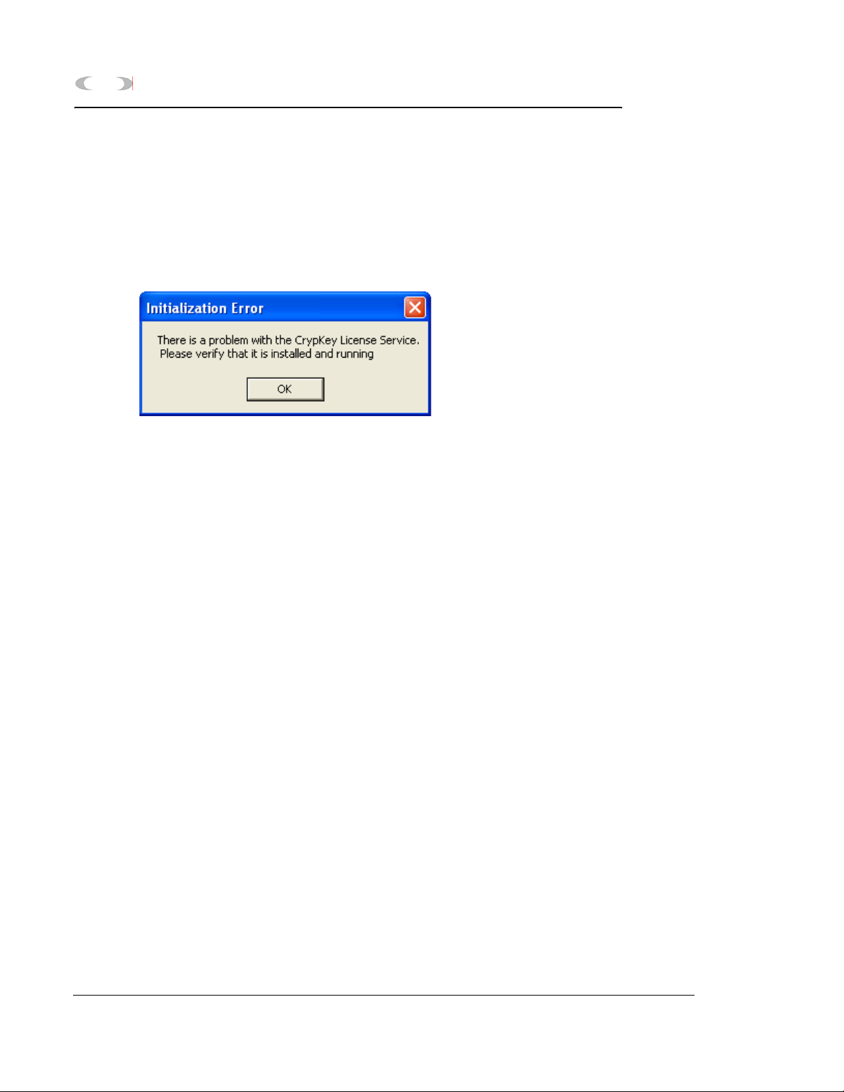
2.3 INSTALLING THE CRYPKEY LICENSE SERVICE FOR MON2000 PLUS
The CrypKey License Service must be installed
on all NT-based systems. If you try to run
MON2000 PLUS before installing the CrypKey
License Service, an error will result.
To install the CrypKey License Service, do the
following:
MON2000
1. After installing MON2000 PLUS, the
program folder should display
automatically; if it doesn’t, open Windows®
Explorer® and access the MON2000 PLUS
program folder.
2. Double-click the SETUPEX.EXE file.
MON2000 PLUS can now be started. You have
30 days to evaluate the application. Once the
trial period expires, you must obtain a license
to continue to use MON2000 PLUS.
for more information, refer to the MON2000
PLUS Quick Start Guide (3-9000-743).
2.4 COPYING MON2000 TO DISKS
Use this procedure to copy the MON2000
installation files to 3 floppy disks for future
installation.
Installing the CrypKey License Service for MON2000 PLUS JULY 2010
Page 31

MON2000
INSTALLATION AND SETUP 2-5
1. Label 3 blank formatted 3.5-inch floppy
disks “MON2000 Install Disk 1”, “MON2000
Install Disk 2”, and “MON2000 Install Disk
3”.
2. Place the MON2000 CD in your CD-ROM
drive.
3. Launch Windows® Explorer®.
4. Ensure that the Show all files option in
Windows® Explorer® is selected.
(a) Use the View > Folder Options menu to
access the Folder Options dialog.
(b) Click the View tab.
(c) In the Advanced Settings pane, find the
gray folder icon labeled Hidden Files.
(d) Click the Show all files radio button.
(e) Click the button.
5. Use the Windows
Explorer® directory tree
®
to open the MON2000 Installation Files
folder on your CD.
6. Place the “MON2000 Install Disk 1” in your
floppy drive.
JULY 2010 Copying MON2000 to Disks
Page 32

2-6 INSTALLATION AND SETUP
7. Open the Disk1 folder on your CD.
8. Copy all files from the Disk1 folder to the
“MON2000 Install Disk 1” floppy.
9. Remove the “MON2000 Install Disk 1” from
your floppy drive.
10.Repeat Steps 5 through 8 to copy the Disk2
and Disk3 folders to your “MON2000 Install
Disk 2” and “MON2000 Install Disk 3”
floppy disks.
11.Remove the MON2000 CD from your
CD-ROM drive.
2.5 TRANSFERRING A MON2000 PLUS LICENSE
To physically transfer the license file from one
computer to the other you will need a
removeable storage medium such as a 3.5-inch
floppy disk or a USB flash drive. Also, there
must be a licensed version on MON2000 PLUS
installed on the source computer and an
unlicensed version of MON2000 PLUS on the
targeted computer.
MON2000
1. On the target computer, if using a floppy
disk, insert it into the disk drive; if using a
flash drive, insert it in to a USB slot.
Transferring a MON2000 PLUS License JULY 2010
Page 33

MON2000
INSTALLATION AND SETUP 2-7
2. Start MON2000 on the target computer.
The License Configuration screen displays.
3. Select Transfer in from another
computer... from the License menu. The
JULY 2010 Transferring a MON2000 PLUS License
Page 34

2-8 INSTALLATION AND SETUP
Transfer License In (Step 1 of 3) screen
displays.
MON2000
4. Click Browse to select a disk path to the
removeable storage medium that holds the
license file. Click OK to accept your
selection.
Transferring a MON2000 PLUS License JULY 2010
Page 35

MON2000
INSTALLATION AND SETUP 2-9
5. Click Next. The Transfer License In (Step 2
of 3) screen displays.
6. Remove the removeable storage medium
from the targeted computer and insert it
into the source computer.
7. Launch MON2000 PLUS on the source
computer. When the startup screen
displays, press Enter. The License
JULY 2010 Transferring a MON2000 PLUS License
Page 36

2-10 INSTALLATION AND SETUP
Configuration screen displays with the
message “Unlimited license”.
MON2000
8. Select Transfer out to another
computer... from the License menu of the
Transferring a MON2000 PLUS License JULY 2010
Page 37

MON2000
INSTALLATION AND SETUP 2-11
License Configuration screen. The Transfer
License Out (Step 1 of 2) screen displays.
9. Click Browse to select a disk path to the
removeable storage medium that holds the
license file. Click OK to accept your
selection.
JULY 2010 Transferring a MON2000 PLUS License
Page 38

2-12 INSTALLATION AND SETUP
10.Click Next. The Transfer License Out (Step
2 of 2) screen displays.
MON2000
Transferring a MON2000 PLUS License JULY 2010
Page 39

MON2000
INSTALLATION AND SETUP 2-13
11.Click Finish. MON2000 PLUS on the
source computer is no longer licensed.
12.Remove the removeable storage medium
from the source computer and reinsert it
into targeted computer.
JULY 2010 Transferring a MON2000 PLUS License
Page 40

2-14 INSTALLATION AND SETUP
13.On the targeted computer, click Next on the
Transfer License In (Step 2 of 3) screen. The
Transfer License In (Step 3 of 3) screen
displays.
MON2000
Transferring a MON2000 PLUS License JULY 2010
Page 41

MON2000
INSTALLATION AND SETUP 2-15
14.Click Finish. The License Configuration
screen displays.
MON2000 PLUS is now licensed for unlimited
use on the targeted computer.
2.6 UNINSTALLING MON2000
To uninstall MON2000 using Windows® 95,
Windows® 98, Windows® 2000 or Windows®
NT,
1. Click the button (see the taskbar).
JULY 2010 Uninstalling MON2000
Page 42

2-16 INSTALLATION AND SETUP
2. Click Settings and then Control Panel. The
Control Panel dialog appears.
3. Double-click the Add/Remove Programs
icon.
MON2000
If using Windows XP, click the Start button, then
Add/Remove Programs.
4. The Add/Remove Program Properties dialog
appears.
5. Select MON2000 and click the
button.
Uninstalling MON2000 JULY 2010
Page 43

MON2000
INSTALLATION AND SETUP 2-17
6. Windows® displays the following
confirmation dialog.
7. Click the button to continue.
Windows® deletes the program files only.
Any files shared by other programs or
created by the user are not deleted.
Click the button to abort and
return to the Add/Remove Program
Properties dialog.
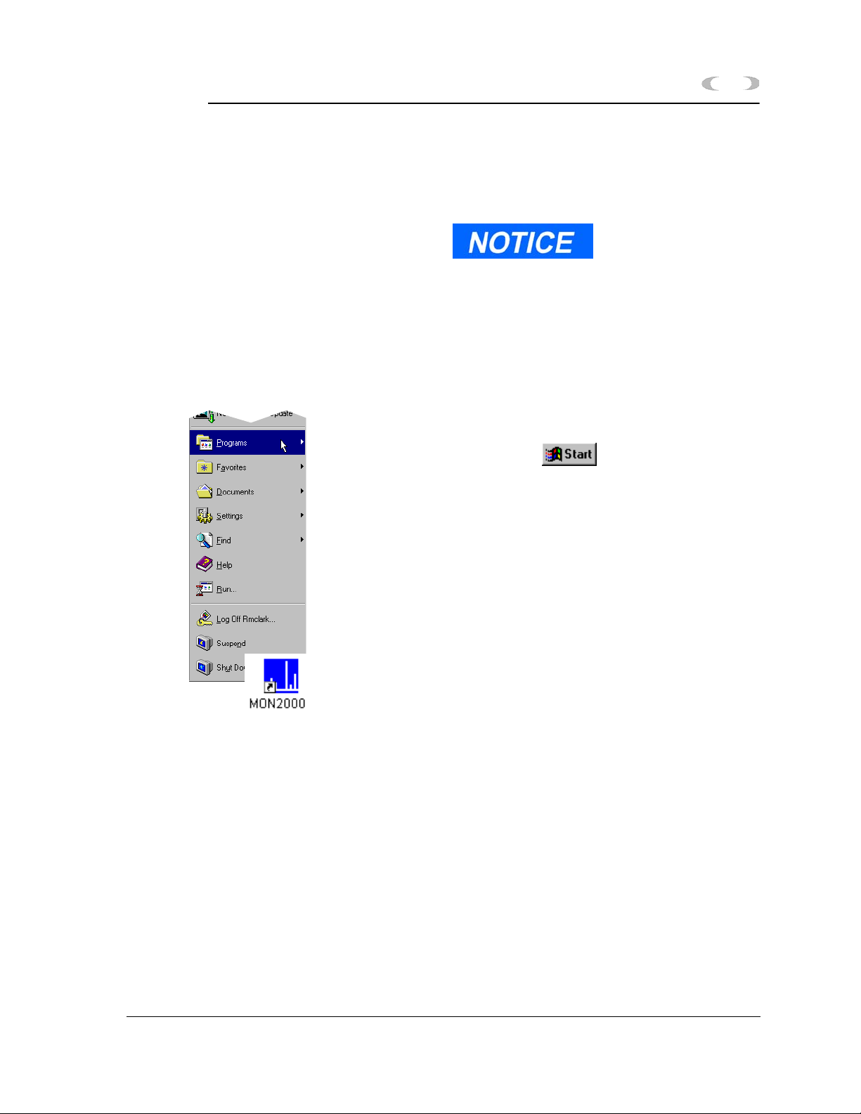
2.7 STARTING MON2000
To start MON2000 after a successful
installation,
Use the Windows® Start menu (Start >
Programs >MON2000 menu) by clicking the
button.
Double-click the MON2000 icon automatically
created on your desktop during installation.
You cannot access the MON2000 functions
until you are successfully logged on.
To start MON2000 directly from the executable
file, use the directory you specified when
installing MON2000. Note that c:\Program
JULY 2010 Starting MON2000
Page 44

2-18 INSTALLATION AND SETUP
Files\MON2000\MON2000 is the default
setting.
2.8 PERFORMING YOUR FIRST LOGON
2.8.1 The Initial Logon
MON2000
Each new GC unit is shipped with one super
user named “Emerson”. After logon, ensure
that this user name appears in the Users list as
a super user (see Section 2.11.1).
To log on for the first time,
1. Start the MON2000 software program by
clicking the desktop icon or by using the
Windows
Start menu (see Section 2.7).
®
2. Click in the User Name data field.
3. Type emerson. Note that the user name is
not case-sensitive.
A PIN is not required for
the initial logon.
Performing Your First Logon JULY 2010
Page 45

MON2000
INSTALLATION AND SETUP 2-19
4. When you have successfully logged on, the
MON2000 main window appears.
2.8.2 Registering MON2000
After your have successfully performed your
initial logon (see Section 2.8.1), MON2000
automatically prompts you to register your
copy of MON2000 software. An active Internet
connection is required for registration.
Registering your MON2000 software allows
you to receive information about free updates
and related products. A direct link to the
Emerson Internet website is provided via the
File > Update MON2000 menu.
You may choose to postpone registration. You
can register at any time via the File > Register
MON2000 menu.
JULY 2010 Registering MON2000
Page 46

2-20 INSTALLATION AND SETUP
1. Use the File>Register MON2000 menu.
Follow the prompts in the Register
MON2000 dialog to input your name,
MON2000 serial number (located inside the
CD jewel case), and other relevant
information.
2. Click the button to continue.
MON2000
3. Choose the desired registration method by
clicking the corresponding radio button.
4. Click the button.
You must have an active
internet connection to
register via the website.
Registering MON2000 JULY 2010
Page 47

MON2000
INSTALLATION AND SETUP 2-21
2.8.3 Update MON2000
Provided there is an active internet connection
to the computer on which MON2000 is
installed, clicking the File>Update MON2000
submenu sends the user to the Emerson®
Chromatograph Controllers website
(www.emersonprocess.com/daniel/products/GC/
Controllers/Productdetail.htm).
Updating the software
requires a previously installed,
registered copy of MON2000.
Use the File>Update MON2000 menu to
download the latest versions of MON2000 and
the BOS software programs.
To download the latest versions of the software,
1. Use the computer on which MON2000 is
installed and connect to the Internet.
Minimize the Internet window.
2. From MON2000, select the File>Update
MON2000 menu. This opens the Emerson
Chromatograph Controllers website
(www.emersonprocess.com/daniel/products/
GC/Controllers/Productdetail.htm).
3. From the Emerson Chromatograph
Controller website, you can download the
latest MON2000 and BOS updates, view
and/or download catalogs, brochures,
equipment specification sheets, product
manuals, drawings, application notes, and
white papers. Other links to products and
services are also available.
JULY 2010 Update MON2000
Page 48

2-22 INSTALLATION AND SETUP
2.9 CHECKLIST FOR SETTING UP MON2000
To ensure optimum performance,
• Configure your system security (see
Section 2.11.1).
Verify that you have assigned a password to
the super user, and/or created a secure
system Admin account.
• Configure how MON2000 will save your
analytic and diagnostic information (see
Section 2.16.2).
• Establish communications between
MON2000 and the GC unit (see Section 2.10
and Section 5.17).
MON2000
2.10 COMMUNICATIONS
MON2000 can communicate to the GC unit
locally via a serial port cable, Ethernet
connection, or remotely via a modem. If
performing a remote connection, ensure that
you have configured the PC modem first.
To configure the communication and serial port
settings for the GC unit, see Section 5.17.
2.10.1 Connect to the GC Unit
1. Use the File > Connect menu or click the
toolbar icon to access the Select GC for
Connect menu.
2. Double-click the desired GC unit.
Checklist for Setting Up MON2000 JULY 2010
Page 49

MON2000
If another user is already
connected to the GC, the unit
will “lock out” the second user.
When a PC connection is
active, the GC Controller front
panel will indicate a “System
Lockout”. This status times out
after 10 minutes.
INSTALLATION AND SETUP 2-23
3. MON2000 appears the connection status
dialog while dialing the selected unit.
The messages “Reading dictionary”,
“Reading GC Application data”’ and “Logon”
appears in the status bar and an
information screen appears.
Once connected, the name of the GC unit
displays in the lower left hand corner of the
MON2000 main window.
2.10.2 Disconnect from GC Unit
Use this process to terminate an active PC
connection to a GC unit.
The menu-driven procedure for disconnecting
is completely optional. MON2000 intelligently
and automatically disconnects when you exit
MON2000 or connect to a second GC
Controller.
1. Use the File > Disconnect menu or click the
toolbar icon to access this function.
2. MON2000 automatically terminates all
open connections.
JULY 2010 Disconnect from GC Unit
Page 50

2-24 INSTALLATION AND SETUP
A Terminating communications message
appears in the status bar.
If MON2000 does not detect an active
connection to terminate, an “Invalid
selection or not downloaded” message
appears.
2.11 CUSTOMIZING MON2000
Use the following functions to customize users,
the directory of GC applications, and PC
communications parameters.
2.11.1 Configure Users
Use this function to create new user accounts
or edit the existing account data. An extra level
of security is assigned to the File>Users
submenu. The File>Users submenu can only be
accessed by first entering a Password into a
dialog box titled 'Enter Administrator
Password'. After gaining access to the Users
dialog, the operator then has the ability to
create new user accounts or edit existing
account data. This feature is not available to
the 'Regular' and 'Read Only' user.
MON2000
1. Use the File > Users menu to access this
function.
2. The Enter Administrator Password dialog
box appears.
Note that the default password admin is
not case sensitive. This password is used as
a security measure to deny unauthorized
Customizing MON2000 JULY 2010
Page 51

MON2000
INSTALLATION AND SETUP 2-25
users access to the MON2000 Users
submenu, which allows Super users to add,
edit, or change security levels.
Click the button. Then the Users
dialog appears.
3. Use the File>Change Administrator menu
to change the Administrator password.
The Change Administrator Password dialog
box appears.
Insert the old password, enter the new
password and confirm the change.
Then, click the button to apply
your changes.
JULY 2010 Configure Users
Page 52

2-26 INSTALLATION AND SETUP
4. To configure a new user or edit existing user
parameters,
(a) Click the appropriate Name cell and type
the desired user name.
Note that the user name is not casesensitive but punctuation (e.g., commas
or spaces) is preserved.
(b) Click the appropriate Type cell and use
the provided combo box to select the
desired security level. Note that there
should be at least one Super user.
(c) Click the appropriate PIN cell and type
the desired PIN for this user. Note that
the PIN is limited to 12 numeric
characters.
MON2000
Super users can write changes
to the GC unit, configure
MON2000, and access the
Users function.
Regular and Read only users
can only view data.
If no PIN is entered, the user can log on
to the MON2000 software program or
the GC unit (via the front panel) with
the assigned user name – that is, no
password will be required.
5. To write user data to the online GC unit,
(a) Click the or press
the F2 key.
(b) MON2000 writes the data to the GC
Controller.
6. Click the button to apply your
changes and return to the main screen.
Click the button to exit and
return to the main screen without applying
your changes.
Configure Users JULY 2010
Page 53

MON2000
INSTALLATION AND SETUP 2-27
2.11.2 Set Up GC Directory
Do not delete any currently
used applications from the GC
Directory. If an entry is
inadvertently deleted, you
may need to reinstall the
application software for that
GC.
This function allows you to set up a directory
listing of all GC units MON2000 can control for
this application. From the GC Directory, you
can configure the PC serial port communication
parameters for a specific GC unit.
Data entered in the GC Directory is stored in
the “Gcdir.dat” file (...\GC\BIN\). The Station
Name is the user assigned name to a GC
location. As GC applications are installed,
MON2000 adds the application name to the GC
Directory.
The GC unit name shown in the GC Status Bar
of the MON2000 main window is entered via
the System dialog (see Section 5.1).
To edit the GC directory,
1. Use the File > GC Directory menu to access
this function.
2. The GC Directory dialog appears.
JULY 2010 Set Up GC Directory
Page 54

2-28 INSTALLATION AND SETUP
3. Press the F1 key to open the MON2000
Application help file for detailed
information about these settings.
MON2000
4. MON2000 is configured with two default
directories:
• Default 1: parameters are set for 9600
baud rate
5. Default 2: parameters are set for 19200
baud rate.
6. Click the appropriate Com ID cell and type
the Modbus communication identification
number (set by DIP switch positions on the
Set Up GC Directory JULY 2010
Page 55

MON2000
INSTALLATION AND SETUP 2-29
GC Controller system interface board) for
the GC unit.
To successfully connect to the GC unit, the
COM IDs specified via the File>GC
Directory and the Application>Serial Ports
dialogs must match. See Section 5.17.1 for
more information.
7. Click the Comments cell to enter any helpful
information regarding a particular GC unit,
such as location or purpose.
8. Use the dynamic pull-down menus to select
the desired PC Port, Baud Rate, Data Bits,
Stop Bits, Parity, and Handshaking
settings.
The following parameters support an auto-detect
setting: Baud Rate, Data Bits, Stop Bits, Parity,
Protocol.
Set any of these parameters to “?” (autodetect) and
MON2000 will conform to the settings used by the GC
unit.
9. Use the provided cells to input RTS On
Delay, RTS Off Delay, and Extra Delay
values.
The Extra Delay field accepts numerical
values (0 to 9000 milliseconds) for
additional time to be added to the current
communication timeout delay.
10.Use the Protocol pull-down menu to select
the desired Modbus communications
protocol.
11.If you plan to connect remotely to the GC
unit via a modem or Ethernet connection,
use the Connection Type (Direct/Remote)
JULY 2010 Set Up GC Directory
Page 56

2-30 INSTALLATION AND SETUP
pull-down menu for a “Direct Connect”
option or a previously configured modem.
2.11.3 Dial-up Connection
Use this command to run the Dial-up dialog to
configure the GC Controller modem. The
default properties from Windows® Control
Panel are used so you must ensure that the
modem connects at the GC Controller’s
configured baud rate. It may be necessary to
enter a modem initialization string.
The Direct Connect option allows you to connect from the PC
to the GC Controller via a serial port, per its default settings.
MON2000
If you select a modem, the modem property dialog appears,
allowing you to change its attributes.
To configure the modem and make a
connection,
1. Use the File>GC Directory menu, and the
GC Directory appears.
2. Click the Station Name data field and click
the Modem Properties button or press the
F2 button.
Dial-up Connection JULY 2010
Page 57

MON2000
INSTALLATION AND SETUP 2-31
3. The Modem Properties dialog appears and
the General Data Connection Modem
Preferences are activated.
The General Data default settings are:
Table 2-1 General Data Connection Preferences
Port Speed
Data Protocol
Compression
Flow Control
19200
Disabled
Disabled
None
JULY 2010 Dial-up Connection
Page 58

2-32 INSTALLATION AND SETUP
4. Click the Advanced tab to configure the
Hardware settings.
MON2000
The Advanced Data default settings are:
Table 2-2 Advanced Data Connection Preferences
Data Bits
Parity
Stop Bits
8
None
1
5. Click the button to apply your
changes, or click the button to
discard the changes and return to the GC
Directory dialog.
Dial-up Connection JULY 2010
Page 59

MON2000
INSTALLATION AND SETUP 2-33
6. Next, from the GC Directory dialog, scroll
over to configure the following parameters:
The Baud Rate, Data Bits, and Stop Bits parameters
were configured above.
Table 2-3 GC Directory Dialog Default Settings
Heading Pull-down Menu Selection
PC Port COM1, COM2,COM3
Handshaking None
RTS On Delay 0
RTS On Delay 0
Extra Delay 0 (See note)
Connection Type
(Direct/Remote)
Telephone Complete number
Server Type IP Address
Retries
• Modem
• IP Address
IC Multiplier 10
Direct Connection
Modem
(Area Code) (XXX-XXXX)
XXX.XX.XX.XXX
(10 digits)
5
3
JULY 2010 Dial-up Connection
Page 60

2-34 INSTALLATION AND SETUP
The Extra Delay is enabled for Ethernet connections.
The default value is “0” and the default 30 seconds timeout is used. If
the value is changed to greater than “0”, the value is used as the
timeout. The entered value is multiplied by 10 inside MON2000,
therefore the maximum timeout is 100,000 ms or 100 seconds (ex: If
timeout value needs to be 15 seconds, the user should enter 1,500).
MON2000
Dial-up Connection JULY 2010
Page 61

MON2000
INSTALLATION AND SETUP 2-35
7. Click the button to accept the
changes. While connecting, MON2000 dials
the number, attempts to connect via the
selected modem and displays progress
messages. A message box appears when a
connection has been made or if the attempt
to connect fails.
Once a connection has been established and
while MON2000 remains connected via the
modem, the Connect button is disabled and
the Disconnect button is enabled.
If the connection fails at any time,
MON2000 displays a message in the GC
Status bar that it has been disconnected.
You can end the connection from the
File>Disconnect menu, by clicking the
disconnect icon on the MON2000 toolbar, or
by exiting MON2000.
If you are using the Modbus RTU protocol, the values for baud
rate, data bits, stop bits, and parity must match the settings
you configured in the Modem Properties dialog.
These values are required to correctly calculate character
timing.
When you start MON2000 after the
parameters are established, you can connect
to the GC via the File>Connect menu or by
clicking the Connection icon on the
MON2000 toolbar.
JULY 2010 Dial-up Connection
Page 62

2-36 INSTALLATION AND SETUP
2.11.4 Modem Initialization Strings/Setup
This section provides “examples” of modem
initialization strings and setups that have been
tested and proven operable. This string of text
characters, known as 'AT commands', has
special meaning to the PC modem and is used
by the modem for every telephone connection
made to a selected GC unit.
To edit or enter a modem initialization string,
use the button and use the Control
Panel > Modems > General > Properties >
Connection > Advanced to access the Advanced
Modem Connection Settings dialog. Enter the
modem initialization string in the Extra
Settings field.
MON2000
Modem Initialization Strings/Setup JULY 2010
Page 63

MON2000
INSTALLATION AND SETUP 2-37
By default, MON2000 provides a modem
initialization string that serves the purpose for
most Hayes-compatible modems. Therefore, in
most cases, you need not enter a different
string.
However, for some modems, you may want to
consult the following pages which document
initialization strings and modem setups that
have been field-tested.
The default initialization string that MON2000 provides is
sent to the PC modem first. Then the custom initialization
string you provide is sent. In this manner, MON2000 sets the
modem parameters that it requires, while you can customize
the modem's operation to respond to special conditions.
Once the optimum modem initialization string has been
determined, it should need no further revision unless a
different brand or model of modem is installed.
Black Box - Modem 325
During development of the GC Controller, a
Black Box Modem 325 was used to test modem
communications with the GC unit. For that test
and that modem, the modem initialization was
set as follows:
\N0\C0\Q0 (where 0 = zero)
JULY 2010 Modem Initialization Strings/Setup
Page 64

2-38 INSTALLATION AND SETUP
Interpretation of the AT commands for that
particular modem was as follows:
• \N0 = normal mode; no error control; data
is buffered (versus ‘direct mode,’ ‘reliable
mode, ’or ‘auto reliable mode’)
• \C0 = disable auto reliable buffer (versus
‘buffer data for 4 seconds or 200 characters’)
• \Q0 = disable flow control (versus ‘enable
XON/XOFF flow control,’ ‘enable unilateral
CTS flow control,’ or ‘enable bilateral CTS/
RTS flow control’)
U.S. Robotics Sportster
The following setup for U.S. Robotics Sportster
28.8 Kbps external FAX-modems was verified
at the GC assembly and checkout lab:
MON2000
• At the GC Controller, the modem DIP
switches were set to 5 and 8 UP, the rest
DOWN.
• At the PC, the modem DIP switches were
set to 2, 4, 6, and 7 UP, the rest DOWN.
Modem Initialization Strings/Setup JULY 2010
Page 65

INSTALLATION AND SETUP 2-39
MON2000
With these switch settings, initialization string
&F was required. See Table 2-4 for further
explanation of these switch settings and the
parameters they control.
Table 2-4 DIP Switch Settings for U.S. Robotics Sportster Modem
Switch Function At GC At PC
1 UP (off) – Normal DTR; computer must provide
DTR signal for modem to accept commands.
DOWN (on) – Modem ignores DTR.
2 UP (off) – Verbal (word) results.
DOWN (on) – Numeric results.
3 UP (off) – Suppress result codes.
DOWN (on) – Enable result codes.
4 UP (off) – Display keyboard commands.
DOWN (on) – Suppress echo.
5 UP (off) – Modem answers on first ring or higher.
DOWN (on) – Disable auto answer.
6 UP (off) – Modem sends carrier detect (CD) signal
on connect, and drops CD on disconnect.
DOWN (on) – CD always on.
7 UP (off) – For power-on and ATZ reset, the Y or Y1
configuration is used from user-defined nonvolatile
memory (NVRAM).
DOWN (on) – For power-on and ATZ reset, the
generic template, &F0, is used from read only
memory (ROM).
8 UP (off) – Disable AT command set recognition.
DOWN (on) – Enable AT command set recognition.
JULY 2010 Modem Initialization Strings/Setup
Page 66

2-40 INSTALLATION AND SETUP
GVC/MaxTech 28.8 Kbps Modem
The following setup for GVC 28.8 Kbps
external Voice/Data/FAX modems was verified
at Daniel Canada. At the GC Controller:
To make these settings for the modem at the GC Controller,
you will need to use a terminal program (such as ProComm o
other commercial modem software) to input the “AT”
commands to the modem before connecting it to the GC
Controller.
AT&F5 Factory default with v.42bis flow control
disabled (must be first).
ATB8 9600 baud
MON2000
Or
ATB11 19200 baud
AT&D0 Modem ignores DTR (not necessary if using a
cable that incorporates the DTR signal from
the Controller).
ATM0 Turn OFF speaker.
ATS0=n n is number of rings for auto answer (e.g.,
ATS0=1, ATS0=2, etc.).
AT&C0 Force carrier detect high
AT%C0 Turn OFF compression.
If compression is turned ON with AT%C1,
or OFF with AT%C0, then the modem at
other end should match.
AT&W0 Write to stored profile “0” (zero).
AT&Y0 Use stored profile “0” (zero) when turned on.
Modem Initialization Strings/Setup JULY 2010
Page 67

MON2000
INSTALLATION AND SETUP 2-41
At the PC, use &F5%C1M0 which indicates
a factory default with v.42bis flow control
disabled / compression ON / speaker OFF.
2.12 2350 TO 2350A RETROFIT INSTRUCTIONS
The 2350A GC Controller CPU assembly has
been designed to include all digital I/O and
COM3 and COM4 serial ports. This eliminates
the requirement (and additional cost) for an I/O
assembly or DSPI/O assembly.
In addition, BOS is now resident in the
DiskOnChip, instead of an EPROM set. The
DiskOnChip provides additional expanded
memory for archiving data, instead of having to
purchase a memory expansion board assembly.
The BOS file in the DiskOnChip may be
upgraded in the field through MON2000.
Optional boards may be plugged directly into
the PC/104 Bus (connectors J19 and J20) on the
CPU board assembly. The COM4A board
provides four additional serial ports (COM5
through COM8). A modem board and/or
Ethernet board may be also be plugged directly
into the PC/104 Bus for additional
communications requirements.
JULY 2010 2350 to 2350A Retrofit Instructions
Page 68

2-42 INSTALLATION AND SETUP
The PC/104 Bus is designed to allow any
combination of option boards to be installed in
any order, with the exception of the CSA
approved Radicom modem board which must be
the top board in the assembly. (see Figure 2-1).
MON2000
Figure 2-1 2350A Controller Card Cage Assembly
If you are using the CSA approved Radicom modem;
ensure that it is the top card in the card cage assembly.
The connection configuration of the Radicom modem
requires installation at the top of the assembly.
2350 to 2350A Retrofit Instructions JULY 2010
Page 69

INSTALLATION AND SETUP 2-43
MON2000
2.13 CONVERSION PROCESS
Use the following process to retrofit a 2350 GC
Controller to a 2350A GC Controller.
1. At the GC Controller site, remove the
Controller enclosure's front panel.
SERIOUS PERSONAL INJURY OR DEATH POSSIBLE
Before removing the unit cover from the GC Controller, make certain the power supply
switch is OFF and the AC power cord is disconnected. Observe all safety precautions
when you are working in a hazardous environment.
Failure to observe all safety precautions could result in serious injury or death.
(a) For the explosion-proof Controller, the
front panel is secured by 16 screws.
Remove those screws first.
(b) Then carefully lower the front panel on
its bottom hinges. The front panel is
heavy, so make sure it does not drop and
cause damage.
(c) For the rack mount Controller, the rear
of the enclosure is open; it allows access
for most field wiring procedures without
removing the enclosure.
2. Locate the GC Controller's Terminal Board
for Field Wiring (TB). The TB is attached to
the GC Controller's card cage assembly,
facing the enclosure's front panel. (In the
rack mount Controller, the TB faces
outward toward the rear of the enclosure.)
3. Loosen the six screws that secure the TB.
Then unplug the TB from its connections at
the back, top of the board.
JULY 2010 Conversion Process
Page 70

2-44 INSTALLATION AND SETUP
4. Lower the TB down and out of the way, held
in place by its ground straps at the bottom
of the board. This exposes the Card Cage
Assembly.
5. Loosen the four screws that secure the Card
Cage Assembly to the chassis. Then remove
the Card Cage Assembly away from its
chassis mount so that it is easy to work on.
6. Locate the System Interface and Driver
board. It is mounted to the top of the Card
Cage Assembly.
7. Remove all cables connected to the System
Interface Board (P/N 3-2350-005,
P/N 3-2350-022, or P/N 3-2350-023).
8. Remove the I/O48 Board assembly (drawing
P/N BE-12973) and cables from the top slot
of the Cage Card Assembly. This board is
not used on the 2350A GC Controller.
MON2000
9. Remove the CPU Board assembly (P/N CE-
19281) and cables from the second slot of
the card cage assembly. This board is not
used on the 2350A GC Controller.
Conversion Process JULY 2010
Page 71

MON2000
INSTALLATION AND SETUP 2-45
10.Remove the DSPI/O board assembly
(drawing P/N CE-12976) and cables from
the third slot of the card cage assembly.
This board is not used on the 2350A GC
Controller.
11.Remove any other optional boards, such as
memory expansion boards and associated
cables. These parts are not used on the
2350A GC Controller.
12.Leave the Analog Board assembly (drawing
P/N BE-18044) with attached cable in the
card cage. This board is used on the 2350A
basic configuration.
13.Change the fuse in the in-line fuse holder
from 1 amp to the 2.5 amp, Slo-Blo fuse
provided. The fuse is located in the cable (P/
N 2-3-2350-069) between the power supply
and the System Interface Board.
14.Ensure that DIP Switches 6, 7, and 8 of S1
are all in the "OFF" position. If the 2350A is
powered up with S8 in the OFF position, it
will delete the current application
(commonly called a "Cold Start").
15.To inspect or change the GC Controller's
COM ID setup at the GC Controller site,
locate the DIP switch as described in the
following steps.
SERIOUS PERSONAL INJURY OR DEATH POSSIBLE
Before removing the unit cover from the GC Controller, make certain the power
supply switch is OFF and the AC power cord is disconnected. Observe all safety
precautions when you are working in a hazardous environment.
Failure to observe all safety precautions could result in serious injury or death.
16.For the explosion-proof Controller, the front
panel is secured by 16 screws. Remove those
screws first.
JULY 2010 Conversion Process
Page 72

2-46 INSTALLATION AND SETUP
(a) Then carefully lower the front panel on
its bottom hinges. The front panel is
heavy, so make sure it does not drop and
cause damage. The DIP switch is located
on the lower left side of the front panel
(see Figure G-2).
MON2000
Figure 2-2 Explosion-Proof Controller Dip Switch
Conversion Process JULY 2010
Page 73

MON2000
INSTALLATION AND SETUP 2-47
17.For rack mount and panel mount
Controllers, use a flat head screw driver to
remove the access panel on the right side of
the card cage assembly (see Figure 2-3).
Figure 2-3 Right Side View Rack and Panel Mount Units
18.Inspect or change the DIP switch settings as
necessary.
(a) See Table 2-5 as a guide.
(b) Make sure you record in the GC
Controller's maintenance records any
changes you make to the switch settings.
• Switches "1" through "5" form a 5-bit
binary number for setting the Modbus
slave address (also known as COM ID or
Device ID.)
• Switch number "1" is the least
significant bit, and switch number "5" is
the most significant bit.
Switch to ON = 1
Switch to OFF = 0
JULY 2010 Conversion Process
Page 74

2-48 INSTALLATION AND SETUP
• Switch "6" is a spare for future use.
Switches "7" and "8" are set as needed
for the presence of an optional LOI
(Local Operator Interface) connected via
COM8 When the COM4A Board is
installed. If the COM4A Board is not
installed, the LOI is connected via
COM4.
Table 2-5 Dip Switch Settings Switch Positions
MON2000
COM ID
1 ON OFF OFF OFF OFF
2 OFF ON OFF OFF OFF
3 ON ON OFF OFF OFF
4 OFF OFF ON OFF OFF
5 ON OFF ON OFF OFF
6 OFF ON ON OFF OFF
7ONONONOFFOFF
8 OFF OFF OFF ON OFF
Clears RAM when unit is powered down
Keeps RAM data when unit is powered down
123 45
RAM CLEAR
Dip Switch Setting Positions
8
ON
OFF
Conversion Process JULY 2010
Page 75

MON2000
INSTALLATION AND SETUP 2-49
2.14 BASIC 2350A CONFIGURATION
At this point, install, if any, all mounting
hardware and optional PC/104 boards onto the
2350A CPU Board.
1. Install the 2350A CPU (P/N 3-2350-090)
into slot 3 of the card cage assembly.
2. Install cables on the CPU Board in the
following sequence:
(a) Digital I/O cable (P/N 3-2350-081) from
CPU J7 to the System Interface Board
J2.
(b) Digital I/O cable (P/N 3-2350-080) from
CPU J4 to the System Interface Board
J3.
(c) COM1, COM2, and the printer cable (P/
N 3-2350-083) from CPU J1 to the
System Interface Board J4, J9, and J11.
(d) COM3 and COM4 can be configured two
different ways. To configure a system
WITHOUT a keyboard and display,
connect cable (P/N 3-2350-084) from
CPU J6 to the System Interface Board
J8 and J10. This provides access to
COM3 on J10 and COM4 on J11 of the
Field Termination board. The serial port
setup in the MON2000 Software for
COM4 must be selected as a PC port.
(e) For a system WITH a keyboard and
display, connect cable (P/N 3-2350-087)
from CPU J6 to the System Interface J8
and J12. This provides access to COM3
on J10 and COM4 is dedicated for use as
a serial interface to the keyboard and
display. COM4 will not be available at
J11 of the Field Termination board.
JULY 2010 BASIC 2350A CONFIGURATION
Page 76

2-50 INSTALLATION AND SETUP
The serial port setup in the MON2000
Software for COM4 must be selected as
Front Panel (see Figure 2-4). If all four
serial ports are required for
communications on a system with
keyboard and display, an optional
COM4A Board must be installed and a
COM7 and COM8 cable (P/N 3-2350-086)
connected (see Figure 2-5). The serial
port setup in the MON2000 Software for
COM8 must be configured as Front
Panel. See Figure G-4b.
(f) Reinstall the Analog cable to J6 on the
System Interface Board.
(g) Place the "Unit Updated to 2350A" label,
included with the upgrade kit, on the
instruction decal located on the inside,
right wall of the explosion-proof units or
on the card cage of the rack or panel
mount units.
MON2000
BASIC 2350A CONFIGURATION JULY 2010
Page 77

MON2000
INSTALLATION AND SETUP 2-51
Figure 2-4 Serial Port 4 with COM4A Board
Figure 2-5 Serial Port 8 with COM4A Board
JULY 2010 BASIC 2350A CONFIGURATION
Page 78

2-52 INSTALLATION AND SETUP
2.15 2350A OPTIONS
The following board configurations are optional
for the Model 500 GC with 2350A Controller.
2.15.1 The COM4A Board
1. To add four additional communications
ports at the GC Controller site, remove the
Controller enclosure's front panel.
SERIOUS PERSONAL INJURY OR DEATH POSSIBLE
Before removing the unit cover from the GC Controller, make certain the power
supply switch is OFF and the AC power cord is disconnected. Observe all safety
precautions when you are working in a hazardous environment.
MON2000
Failure to observe all safety precautions could result in serious injury or death.
(a) For the explosion-proof Controller, the
front panel is secured by 16 screws.
Remove those screws first.
(b) Then carefully lower the front panel on
its bottom hinges. The front panel is
heavy, so make sure it does not drop and
cause damage.
(c) For the rack mount Controller, the rear
of the enclosure is open; it allows access
for most field wiring procedures without
removing the enclosure.
2. Locate the GC Controller's Terminal Board
for Field Wiring (TB). The TB is attached to
the GC Controller's Card Cage Assembly,
facing the enclosure's front panel. (In the
rack mount Controller, the TB faces
outward toward the rear of the enclosure.)
3. Loosen the six screws that secure the TB.
Then unplug the TB from its connections at
the back, top of the board.
2350A Options JULY 2010
Page 79

MON2000
INSTALLATION AND SETUP 2-53
4. Lower the TB down and out of the way, held
in place by its ground straps at the bottom
of the board. This exposes the Card Cage
Assembly.
5. Loosen the four screws that secure the Card
Cage Assembly to the chassis. Then remove
the Card Cage Assembly away from its
chassis mount so that it is easy to work on.
6. Locate the System Interface and Driver
board. It is mounted to the top of the Card
Cage Assembly.
(a) Disconnect the Analog cable from J6 on
the System Interface Board, then
disconnect all CPU cables from the
System Interface Board.
(b) Remove the CPU assembly and install
the COM4A Board, with associated
mounting hardware to J19 and J20 PC/
104 Bus connector on the CPU assembly.
(c) Connect COM5 (P22) and COM6 (P23)
on the Field Termination board via cable
(P/N 3-2350-085) to J6 on COM4A.
(d) Connect COM7 (P24) on the Field
Termination board and COM8 via cable
(P/N 3-2350-086) to J3 on COM4A.
(e) Install the CPU assembly into the third
slot of card cage. Connect the CPU cables
as detailed in Section 6.3 Basic 2350A
Configuration.
(f) Install the DB9 connector from COM5 to
P22 on the Field Termination board with
jackpost assemblies.
(g) Install the DB9 connector from COM6 to
P23 on the Field Termination board with
jackpost assemblies.
(h) Install the DB9 connector from COM7 to
P24 on the Field Termination board with
jackpost assemblies.
JULY 2010 The COM4A Board
Page 80

2-54 INSTALLATION AND SETUP
(i) Install the ten position connector from
COM8 to J12 on the System Interface
Board.
(j) Connect the Analog cable to J6 on the
System Interface Board.
With COM4A Boards installed, Serial Port 8 is
usually assigned via MON2000 Application>Serial Ports menu. Select Front Panel
from the Usage pull-down menu (see Figure 2-6
and Figure 2-7).
MON2000
Figure 2-6 Serial Port 4 with COM4A Board
Figure 2-7 Serial Port 8 with COM4A Board
The COM4A Board JULY 2010
Page 81

MON2000
INSTALLATION AND SETUP 2-55
2.15.2 2350A Modem Installation
To install the Internal Modem for the 2350A
GC Controller, follow these steps:
Refer to P/N 3-9000-537 2350A GC Hardware manual
for COM settings and pinouts.
1. To add a modem, at the GC Controller site,
remove the Controller enclosure's front
panel.
(a) For the explosion-proof Controller, the
front panel is secured by 16 screws.
Remove those screws first.
(b) Then carefully lower the front panel on
its bottom hinges. The front panel is
heavy, so make sure it does not drop and
cause damage.
(c) For the rack mount Controller, the rear
of the enclosure is open; it allows access
for most field wiring procedures without
removing the enclosure.
2. Locate the GC Controller's Terminal Board
for Field Wiring (TB). The TB is attached to
the GC Controller's Card Cage Assembly,
facing the enclosure's front panel. (In the
rack mount Controller, the TB faces
outward toward the rear of the enclosure.)
3. Loosen the six screws that secure the TB.
Then unplug the TB from its connections at
the back, top of the board.
4. Lower the TB down and out of the way, held
in place by its ground straps at the bottom
of the board. This exposes the Card Cage
Assembly.
JULY 2010 2350A Modem Installation
Page 82

2-56 INSTALLATION AND SETUP
5. Loosen the four screws that secure the Card
Cage Assembly to the chassis. Then remove
the Card Cage Assembly away from its
chassis mount so that it is easy to work on.
6. Locate the System Interface and Driver
board. It is mounted to the top of the Card
Cage Assembly.
(a) Disconnect the Analog cable from J6 on
the System Interface Board, then
disconnect all CPU cables from the
System Interface Board.
(b) Remove the CPU assembly and install
the COM4A Board, with associated
mounting hardware to J19 and J20 PC/
104 Bus connector on the CPU assembly.
MON2000
If an option board is already plugged into the PC/104 bus
on the CPU, the modem and mounting hardware will be
installed into the PC/104 connector on the option board.
Figure 2-8 Modem Piggy-backed on CPU Board
2350A Modem Installation JULY 2010
Page 83

MON2000
INSTALLATION AND SETUP 2-57
(c) Plug one end of the modem extension
cable (P/N 3-2350-075) into J1 of the
modem assembly. The in-line jack on the
remaining end of the modem extension
cable attaches to the lower left inside
wall of the card cage shield (after the
CPU assembly is reinstalled and all
cables reconnected to the System
Interface board). No software setup is
required for this board.
7. To use an existing Modem (1414):
(a) For operation with the 2350A CPU, set
the Standard 1414 Modem jumpers per
the following table:
Table 2-6 1414 (Standard) Modem Jumper Settings
Jumper Pin
J4/J5 Open
J6 3-5, 4-6
J7 7-8
J9 Open
(b) On the 2350A WinSystems CPU, set J21,
pin 13-14.
JULY 2010 2350A Modem Installation
Page 84

2-58 INSTALLATION AND SETUP
2.15.3 2350A Ethernet Installation
To add an ethernet assembly:
1. To add an ethernet card at the GC
Controller site, remove the Controller
enclosure's front panel.
(a) For the explosion-proof Controller, the
front panel is secured by 16 screws.
Remove those screws first.
(b) Then carefully lower the front panel on
its bottom hinges. The front panel is
heavy, so make sure it does not drop and
cause damage.
(c) For the rack mount Controller, the rear
of the enclosure is open; it allows access
for most field wiring procedures without
removing the enclosure.
MON2000
(d) Locate the GC Controller's Terminal
Board for Field Wiring (TB). The TB is
attached to the GC Controller's Card
Cage Assembly, facing the enclosure's
front panel. (In the rack mount
Controller, the TB faces outward toward
the rear of the enclosure.)
2. Loosen the six screws that secure the TB.
Then unplug the TB from its connections at
the back, top of the board.
3. Lower the TB down and out of the way, held
in place by its ground straps at the bottom
of the board. This exposes the Card Cage
Assembly.
4. Loosen the four screws that secure the Card
Cage Assembly to the chassis. Then remove
the Card Cage Assembly away from its
chassis mount so that it is easy to work on.
2350A Ethernet Installation JULY 2010
Page 85

MON2000
INSTALLATION AND SETUP 2-59
5. Locate the System Interface and Driver
board. It is mounted to the top of the Card
Cage Assembly.
(a) Disconnect the Analog cable from J6 on
the System Interface Board, then
disconnect all CPU cables from the
System Interface Board.
(b) Remove the CPU assembly and install
the COM4A Board, with associated
mounting hardware to J19 and J20 PC/
104 Bus connector on the CPU assembly.
If an option board is already plugged into the PC/104 bus
on the CPU, the ethernet card and mounting hardware
will be installed into the PC/104 connector on the option
board.
If you are using the CSA approved Radicom modem;
ensure that it is the top card in the card cage assembly.
The connection configuration of the Radicom modem
requires installation at the top of the assembly.
(c) Plug one end of the Ethernet extension
cable (P/N 3-2350-088) into J5 of the
Ethernet assembly.
6. The in-line jack on the remaining end of the
Ethernet extension cable attaches to the
lower left inside wall of the card cage shield,
after the CPU assembly is reinstalled and
all cables reconnected to the System
Interface board (see Table 2-7 and Table 2-8
below).
JULY 2010 2350A Ethernet Installation
Page 86

2-60 INSTALLATION AND SETUP
No software setup is required for this board.
Table 2-7 System Interface Board Cable Connections
Connection Ribbon Cable
J5 and J6 Analog I/O
J8 Com3
J10 Com4
J4 Printer
J11 Com2
J2 and J3 Digital I/O
J12 Front Panel and Keyboard
(if installed)
MON2000
Table 2-8 CPU Board Cable Connections
Connection Ribbon Cable
J1 Com1, Com2, and Printer
J4 and J7 Digital I/O
J6 Com3 and Com4
(a) If the 2350A BOS version is v1.84 or
later, ensure that J6 Jumper on pins 1314 of J1 has been removed.
(see Figure 2-9 and Figure 2-10).
7. If a modem is installed, remove the phone
cord.
8. Install the Ethernet card and set the
jumpers as shown below.
2350A Ethernet Installation JULY 2010
Page 87

MON2000
INSTALLATION AND SETUP 2-61
Figure 2-9 Ethernet Jumper Configuration BOS v1.82 and Earlier
Figure 2-10 Ethernet Jumper Configuration BOS v1.84 and Later
JULY 2010 2350A Ethernet Installation
Page 88
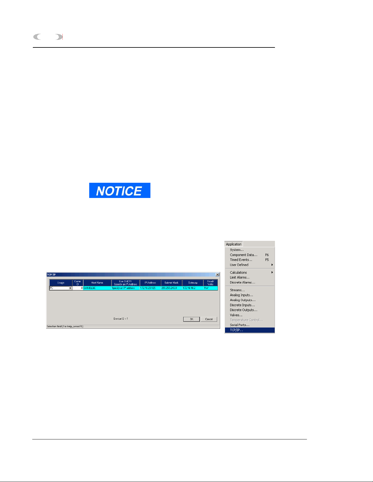
2-62 INSTALLATION AND SETUP
2.15.4 Ethernet TCP/IP Settings
If you plan to connect via an Ethernet
connection, use the following instructions.
To configure the Ethernet TCP/IP settings for
the 2350A GC Controller:
1. Obtain the IP Address, Subnet Mask, and
Gateway addresses (numbers) for the
Target 2350A GC Controller from your
supervisor or Information Technology
Department.
If the controller has never been configured for Ethernet
communications, logon to the Model 500 GC using either the
Direct Connect option, or connect remotely via a Modem.
MON2000
2. Use the Application > TCP/IP menu to
access this function.
3. The TCP/IP dialog appears.
4. Go to the Use DHCP/Specify an IP Address
field and select Specify an IP Address.
5. In the IP Address field, enter the IP Address
(number) obtained from your Supervisor or
the Information Technology Department.
Ethernet TCP/IP Settings JULY 2010
Page 89

MON2000
INSTALLATION AND SETUP 2-63
6. In the Subnet Mask field, enter the subnet
mask address (number) obtained from your
Supervisor or the Information Technology
Department.
7. In the Gateway Address field, enter the
Gateway Address (number) obtained from
your Supervisor or the Information
Technology Department.
8. Click the button to apply all
changes.
9. Disconnect from the controller, using the
toolbar icon or by using the File>Disconnect
menu.
JULY 2010 Ethernet TCP/IP Settings
Page 90

2-64 INSTALLATION AND SETUP
2.15.5 MON2000 TCP/IP Settings
To configure the Ethernet TCP/IP settings for
the MON2000,
1. From the File menu, select GC Directory.
2. Ensure that an Ethernet location has been
created or an existing location modified and
that an Ethernet card installed in the PC
has been selected in the field labeled
Connection Type (Direct/Remote).
MON2000
MON2000 TCP/IP Settings JULY 2010
Page 91

MON2000
INSTALLATION AND SETUP 2-65
3. Enter the same 'IP Address' into the Server
Name/IP Address field of the GC Directory
that was previously entered in the GC
Controller (see Section 2.11.2).
4. Set the number of retries to three.
Click the button to apply your
changes.
JULY 2010 MON2000 TCP/IP Settings
Page 92

2-66 INSTALLATION AND SETUP
2.16 CONNECT VIA GC EXTERNAL MODEM
Ensure you have a pre-existing PC connection to the GC
unit before installing the external modem. If the GC unit is
already on location, do this via another remote operator
connection, or, onsite, via use of a portable PC and serial
cable. Ideally, configure the GC unit and install the
external modem prior to placement at the remote location.
Note: You cannot set the Serial Ports parameters from the
GC unit front panel.)
2.16.1 HARDWARE SETUP
1. Halt any ongoing analysis runs.
Use the Control > Halt menu to access this
function.
MON2000
2. Disconnect AC power from the GC
Controller.
SERIOUS PERSONAL INJURY OR DEATH POSSIBLE
Before removing the unit cover from the GC Controller, make certain the
power supply switch is OFF and the AC power cord is disconnected. Observe
all safety precautions when you are working in a hazardous environment.
Failure to observe all safety precautions could result in serious injury or death.
3. For the explosion-proof Controller, remove
the cover from the GC Controller housing to
expose the GC Controller Terminal Board
for field wiring.
For the rack mount Controller, the rear of
the enclosure is open; it allows access for
most field wiring procedures without
removing the enclosure.
CONNECT VIA GC EXTERNAL MODEM JULY 2010
Page 93

MON2000
INSTALLATION AND SETUP 2-67
4. Connect a custom-made serial line cable (for
RS-232 serial transmission) from the serial
port of the external modem to an available
serial port on the GC Controller Terminal
Board for field wiring.
Special hardware modifications may be needed when
operating an external GC modem from the GC serial ports 3 or
4 (COM3 or COM4), as follows:
• DE-20782 (see drawing addendum of Model 500 Gas
Chromatograph System Hardware Reference Manual,
P/N 3-9000-537).
• Transient protection modules M7 and/or M4, located on the
back side of the GC Controller Terminal Board for field
wiring, may need replacement with the transient protection
modules for RS-232 signals (P/N 3-2350-027). Note that
M4 serves COM3 and M7 serves COM4.
• Make note of the serial port number you
choose for connection. You will need this
information later to make appropriate
software settings.
• Use an RS-232 serial cable no longer
than 50 feet. Longer distances may
result in spurious loss or corruption of
transmitted data.
• See Section 5.17, for details of GC
Controller serial port connectivity (i.e.,
port locations, pinouts, connector types,
gender, cabling, etc.).
5. Connect a telephone line (from wall phone
jack, if available) to the phone jack for the
external modem.
6. Set external modem for Auto Answer (see
external modem user manual).
JULY 2010 Hardware Setup
Page 94

2-68 INSTALLATION AND SETUP
2.16.2 Select Program Settings
This function allows you to configure where
database, GC applications, and Modbus Test
program files are stored.
1. Use the File > Program Settings menu to
access this function.
2. The Program Settings dialog appears.
MON2000
3. To use a Chromatogram file extension other
than the default (e.g. .CGM) or to select the
location of saved data, GC database, and GC
application files,
• click in the Chromatogram file extension
data field and type the desired file
extension
• click in the appropriate data field and
type the desired directory,
Or
• click the button and use the
directory tree to select the desired
location
Select Program Settings JULY 2010
Page 95

MON2000
Table 2-9 Optional Program Settings
Setting Function
INSTALLATION AND SETUP 2-69
4. Use the provided check boxes to turn the
following settings on/off. Note that the
default settings are ON.
Editing replaces existing text
in tables
Prompt to confirm discard
changes
Prompt to confirm save
changes
Synchronize GC Controller’s
time to PC on download, etc.
Tab from spreadsheet to next
control
Enable display in PPM If enabled, percentages less than 0.99%
If enabled, replaces selected table cell
entry with user input.
If disabled, appends user input to end of
the selected table cell entry.
Display confirmation dialog before
exiting a dialog that contains changed
data.
Display confirmation dialog before saving
changed data.
Program the GC Controller clock to
match the PC clock upon download.
Move from field to field and button to
button (rather than from cell to cell
within a spreadsheet or tabular display).
are displayed in PPM (parts per million)
rather than as a percentage.
5. Click the button to apply your
changes and return to the main screen.
Click the button to exit and
return to the main screen without applying
your changes.
JULY 2010 Select Program Settings
Page 96

2-70 INSTALLATION AND SETUP
2.16.3 Generate PC Config Report
This function allows you to generate or print
out a report of the currently active GC
application control settings. See Appendix A for
a sample print-out of a PC Config Report.
To view a PC Config Report already saved to
disk, see Section 7.1.2.
1. Use the File > PC Config Report menu to
access this function. The PC Config Report
dialog appears.
2. Click the check boxes (see Select column) to
choose the data you want included in the
configuration report.
MON2000
Output data for the PC Config
Report depends on the GC
Controller and its application.
Click the button or press the
F2
key to select all options.
Click the button or press F3 to
deselect (i.e., clear) all checked options.
Generate PC Config Report JULY 2010
Page 97

MON2000
If you want to use the
standard Windows
Print dialog to select a
printer, deselect the Use
default printer option.
INSTALLATION AND SETUP 2-71
3. Use the Output radio buttons to either save
the report to disk, print the report with or
without form feeds, or display the report via
the report viewer (see Section 7.1).
®
The File option will open the Save As dialog,
with CONFIG.TXT as the default file name.
The Printer (with form feeds) option will
print the report, with form feeds, to your
configured printer (see Section 3.7).
The Printer (without form feeds) option will
print the report, without form feeds, to your
configured printer (see Section 3.7).
The Screen option will launch the report
viewer (see Section 7.1).
4. Click the button or press the F4
key to generate your customized PC Config
Report.
If you are online with the GC Controller, a PC Config
Report that includes all options can require up to 20
minutes to generate and save. Printing a full report can
take longer.
If you press the ESC key, MON2000 will stop after the
current option is completed.
A progress bar appears, indicating the
completion status.
JULY 2010 Generate PC Config Report
Page 98

2-72 INSTALLATION AND SETUP
2.17 DOWNLOADING AN APPLICATION
This function allows the MON2000 operator to
download applications to GC Controllers. GC
applications with the .APP extension can only
be down loaded to 2350A GC Controllers and
Model 700 units. The Download feature is NOT
available if the keylock switch is closed.
At the end of the download process, MON2000
displays the Set GC Time dialog, which allows
you to accept or change the GC Controller's
date and time.
Only download an application when performing
an initial startup, downloading a new GC
application, or after the GC unit has been out of
service. You must first connect to the GC to use
the Download function.
MON2000
1. Use the File > Download menu to access the
Select GC Application File To Download
dialog.
Downloading an Application JULY 2010
Page 99

MON2000
INSTALLATION AND SETUP 2-73
2. Click the desired .app file. The file name
appears in the File name data field.
GC application files contain all control settings and
application program functions (see Section 5) specific
to a particular GC Controller.
For 2350A GC Controllers and the Model 700
controller, application files (.app files) are normally
stored in the \GC\APP directory.
3. Click the button to download the
selected application file to the connected GC
unit.
Click the button to exit and
return to the main window.
4. MON2000 reads the time at the GC
Controller and the Set Time dialog appears
appears for you to edit or accept (see
Section 4.7.2 for more information).
5. A progress bar appears, indicating the
completion status. See Table 2-10 for a
listing of the automatically enabled function
keys.
JULY 2010 Downloading an Application
Page 100

2-74 INSTALLATION AND SETUP
Table 2-10 Main Menu Function Keys Enabled by Download
Key Function Description
F1 Help Access context-sensitive online help.
F2 Start Auto Sequence Initialize the Auto-Sequencing function.
F3 Halt Stop a function at the end of the current
F5 Edit TEVs Display the Timed Event Tables. This
F6 Edit CDTs Display the Component Data Tables. This
MON2000
This function is also available via the
Control > Auto Sequence menu.
cycle. This function is also available via the
Control > Halt menu.
function is also available via the Application
> Timed Events menu.
function is also available via the Application
> Component Data menu.
F7 View Current CGM Display chromatogram of the stream
currently being analyzed. This function is
also available via the Chromatogram menu.
F8 View Last CGM Display chromatogram stored in the GC
unit. This function is also available via the
Chromatogram menu.
Downloading an Application JULY 2010
 Loading...