

Page 1
Configuration and Use Manual
MMI-20020964, Rev AB
Micro Motion® Fork Viscosity Meters (FVM)
Configuration and Use Manual
June 2014
Page 2

Safety and approval information
This Micro Motion product complies with all applicable European directives when properly installed in accordance with the
instructions in this manual. Refer to the EC declaration of conformity for directives that apply to this product. The EC declaration of
conformity, with all applicable European directives, and the complete ATEX Installation Drawings and Instructions are available on
the internet at www.micromotion.com or through your local Micro Motion support center.
Information affixed to equipment that complies with the Pressure Equipment Directive can be found on the internet at
www.micromotion.com/documentation.
For hazardous installations in Europe, refer to standard EN 60079-14 if national standards do not apply.
Emerson Flow customer service
Email:
• Worldwide: flow.support@emerson.com
• Asia-Pacific: APflow.support@emerson.com
Telephone:
North and South America Europe and Middle East Asia Pacific
United States 800-522-6277 U.K. 0870 240 1978 Australia 800 158 727
Canada +1 303-527-5200 The Netherlands +31 (0) 318 495 555 New Zealand 099 128 804
Mexico +41 (0) 41 7686 111 France 0800 917 901 India 800 440 1468
Argentina +54 11 4837 7000 Germany 0800 182 5347 Pakistan 888 550 2682
Brazil +55 15 3413 8000 Italy 8008 77334 China +86 21 2892 9000
Venezuela +58 26 1731 3446 Central & Eastern +41 (0) 41 7686 111 Japan +81 3 5769 6803
Russia/CIS +7 495 981 9811 South Korea +82 2 3438 4600
Egypt 0800 000 0015 Singapore +65 6 777 8211
Oman 800 70101 Thailand 001 800 441 6426
Qatar 431 0044 Malaysia 800 814 008
Kuwait 663 299 01
South Africa 800 991 390
Saudia Arabia 800 844 9564
UAE 800 0444 0684
Page 3

Contents
Contents
Part I Getting Started
Chapter 1 Before you begin ............................................................................................................3
1.1 About this manual ....................................................................................................................... 3
1.2 Model codes and device types ..................................................................................................... 3
1.3 Communications tools and protocols .......................................................................................... 4
1.4 Additional documentation and resources .................................................................................... 4
Chapter 2 Quick start .....................................................................................................................5
2.1 Power up the transmitter .............................................................................................................5
2.2 Check meter status ......................................................................................................................5
2.3 Make a startup connection to the transmitter ..............................................................................6
Part II Configuration and commissioning
Chapter 3 Introduction to configuration and commissioning ....................................................... 11
3.1 Default values ............................................................................................................................11
3.2 Enable access to the off-line menu of the display ....................................................................... 11
3.3 Disable HART security ................................................................................................................11
3.4 Set the HART lock ...................................................................................................................... 14
3.5 Restore the factory configuration .............................................................................................. 14
Chapter 4 Configure process measurement ..................................................................................17
4.1 Verify the calibration factors ......................................................................................................17
4.1.1 Calibration factors ...................................................................................................... 18
4.2 Configure line viscosity measurement ....................................................................................... 18
4.2.1 Configure Viscosity Measurement Unit ..............................................................................19
4.2.2 Configure Viscosity Damping .......................................................................................... 20
4.3 Configure line density measurement ........................................................................................ 21
4.3.1 Configure Density Measurement Unit ................................................................................21
4.3.2 Configure Density Damping ............................................................................................ 23
4.3.3 Configure Density Cutoff ................................................................................................ 24
4.3.4 Configure two-phase flow parameters ........................................................................24
4.4 Configure temperature measurement .......................................................................................26
4.4.1 Configure Temperature Measurement Unit ........................................................................ 26
4.4.2 Configure Temperature Damping .....................................................................................27
4.4.3 Configure Temperature Input .......................................................................................... 28
4.5 Configure the pressure input ..................................................................................................... 32
4.5.1 Configure the pressure input using ProLink III ............................................................. 32
4.5.2 Configure the pressure input using the Field Communicator .......................................33
4.5.3 Options for Pressure Measurement Unit ........................................................................... 34
4.6 Configure referred viscosity measurement ................................................................................ 35
4.6.1 Configure referred viscosity measurement, ASTM D341 Single-Curve method ........... 36
4.6.2 Configure referred viscosity measurement, ASTM D341 Multi-Curve method .............41
4.6.3 Configure referred viscosity measurement, Matrix Referral method ........................... 46
Configuration and Use Manual i
Page 4

Contents
4.7 Set up the API referral application ..............................................................................................53
4.7.1 Set up the API referral application using ProLink III ...................................................... 54
4.7.2 Set up the API referral application using the Field Communicator ............................... 59
4.8 Set up concentration measurement .......................................................................................... 66
4.8.1 Preparing to set up concentration measurement ........................................................66
4.8.2 Set up concentration measurement using ProLink III ...................................................67
4.8.3 Set up concentration measurement using the Field Communicator ............................74
4.8.4 Using equations to calculate specific gravity, °Baumé, °Brix, °Plato, and °Twaddell ......79
4.8.5 Matrix switching ......................................................................................................... 80
4.8.6 Measuring Net Mass Flow Rate and Net Volume Flow Rate ..........................................82
4.9 Set up flow rate measurement ...................................................................................................82
4.9.1 Set up flow rate measurement using ProLink III ...........................................................82
4.9.2 Set up flow rate measurement using the Field Communicator .................................... 84
Chapter 5 Configure device options and preferences ....................................................................87
5.1 Configure the transmitter display .............................................................................................. 87
5.1.1 Configure the language used for the display ............................................................... 87
5.1.2 Configure the process variables and diagnostic variables shown on the display ...........88
5.1.3 Configure the number of decimal places (precision) shown on the display ..................88
5.1.4 Configure the refresh rate of data shown on the display ..............................................89
5.1.5 Enable or disable automatic scrolling through the display variables ............................ 89
5.2 Enable or disable operator actions from the display ...................................................................90
5.2.1 Enable or disable the Acknowledge All Alerts display command ....................................... 90
5.3 Configure security for the display menus .................................................................................. 91
5.4 Configure alert handling ............................................................................................................92
5.4.1 Configure Fault Timeout .................................................................................................92
5.4.2 Configure Status Alert Severity ........................................................................................93
5.5 Configure informational parameters ......................................................................................... 95
Chapter 6 Integrate the meter with the control system ................................................................97
6.1 Configure Channel B ..................................................................................................................97
6.2 Configure the mA output .......................................................................................................... 98
6.2.1 Configure mA Output Process Variable ............................................................................. 98
6.2.2 Configure Lower Range Value (LRV) and Upper Range Value (URV) ..................................100
6.2.3 Configure Added Damping ........................................................................................... 101
6.2.4 Configure mA Output Fault Action and mA Output Fault Level .............................................103
6.3 Configure the discrete output ................................................................................................. 104
6.3.1 Configure Discrete Output Source ..................................................................................104
6.3.2 Configure Discrete Output Polarity ................................................................................. 105
6.3.3 Configure Discrete Output Fault Action ........................................................................... 106
6.4 Configure an enhanced event ..................................................................................................107
6.5 Configure HART/Bell 202 communications ..............................................................................108
6.5.1 Configure basic HART parameters ............................................................................ 108
6.5.2 Configure HART variables (PV, SV, TV, QV) ................................................................109
6.5.3 Configure burst communications ............................................................................. 111
6.6 Configure Modbus communications ........................................................................................115
6.7 Configure Digital Communications Fault Action ............................................................................... 117
6.7.1 Options for Digital Communications Fault Action ...............................................................117
Chapter 7 Completing the configuration .................................................................................... 119
7.1 Test or tune the system using sensor simulation ......................................................................119
7.2 Back up transmitter configuration ........................................................................................... 119
7.3 Enable HART security ...............................................................................................................120
ii Micro Motion® Fork Viscosity Meters (FVM)
Page 5

Contents
Part III Operations, maintenance, and troubleshooting
Chapter 8 Transmitter operation ................................................................................................125
8.1 Record the process variables ................................................................................................... 125
8.2 View process variables .............................................................................................................125
8.2.1 View process variables using the display ...................................................................126
8.2.2 View process variables and other data using ProLink III ............................................. 126
8.2.3 View process variables using the Field Communicator .............................................. 127
8.3 View and acknowledge status alerts ........................................................................................ 127
8.3.1 View and acknowledge alerts using the display ........................................................ 127
8.3.2 View and acknowledge alerts using ProLink III ...........................................................129
8.3.3 View alerts using the Field Communicator ................................................................ 130
8.3.4 Alert data in transmitter memory ............................................................................. 130
Chapter 9 Measurement support ............................................................................................... 133
9.1 Perform the Known Density Verification procedure .................................................................133
9.1.1 Perform the Known Density Verification procedure using the display ....................... 133
9.1.2 Perform the Known Density Verification procedure using ProLink III ......................... 134
9.1.3 Perform the Known Density Verification procedure using the
Field Communicator ................................................................................................. 135
9.2 Adjust viscosity measurement with Viscosity Offset ....................................................................136
9.3 Adjust viscosity measurement with Viscosity Meter Factor ...........................................................137
9.3.1 Adjust viscosity measurement with Viscosity Meter Factor using the display ................. 137
9.3.2 Adjust viscosity measurement with Viscosity Meter Factor using ProLink III ................... 138
9.3.3 Adjust viscosity measurement with Viscosity Meter Factor using the
Field Communicator ................................................................................................. 139
9.3.4 Calculate and enter Viscosity Meter Factor manually ..................................................... 141
9.4 Adjust density measurement with Density Offset or Density Meter Factor ....................................... 142
9.5 Perform density offset calibration ............................................................................................143
9.5.1 Perform density offset calibration using the display .................................................. 143
9.5.2 Perform density offset calibration using ProLink III ....................................................145
9.5.3 Perform density offset calibration using the Field Communicator ............................. 146
9.6 Adjust temperature measurement with Temperature Offset or Temperature Slope ......................... 147
9.7 Perform temperature calibration .............................................................................................148
9.7.1 Perform temperature calibration using the display ................................................... 148
9.7.2 Perform temperature calibration using ProLink III ..................................................... 149
9.7.3 Perform temperature calibration using the Field Communicator .............................. 150
9.8 Adjust concentration measurement with Trim Offset .................................................................151
9.9 Adjust concentration measurement with Trim Offset and Trim Slope ........................................... 152
9.10 Set up user-defined calculations .............................................................................................. 154
9.10.1 Equations used in user-defined calculations ..............................................................156
9.10.2 Measurement units used in user-defined calculations ............................................... 157
Chapter 10 Troubleshooting ........................................................................................................ 159
10.1 Quick guide to troubleshooting ...............................................................................................159
10.2 Check power supply wiring ......................................................................................................160
10.3 Check grounding .....................................................................................................................161
10.4 Perform loop tests ...................................................................................................................161
10.4.1 Perform loop tests using the display .........................................................................162
10.4.2 Perform loop tests using ProLink III ........................................................................... 163
10.4.3 Perform loop tests using the Field Communicator .................................................... 164
Configuration and Use Manual iii
Page 6

Contents
10.5 Status LED states ..................................................................................................................... 166
10.6 Status alerts, causes, and recommendations ........................................................................... 167
10.7 Viscosity measurement problems ........................................................................................... 172
10.8 Density measurement problems ............................................................................................. 174
10.9 Temperature measurement problems .....................................................................................175
10.10 API referral problems ...............................................................................................................175
10.11 Concentration measurement problems ...................................................................................176
10.12 Milliamp output problems ....................................................................................................... 177
10.13 Discrete output problems ........................................................................................................178
10.14 Time Period Signal (TPS) output problems ...............................................................................179
10.15 Using sensor simulation for troubleshooting ........................................................................... 179
10.16 Trim mA outputs ..................................................................................................................... 180
10.16.1 Trim mA outputs using ProLink III ..............................................................................180
10.16.2 Trim mA outputs using the Field Communicator .......................................................180
10.17 Check HART communications ................................................................................................. 181
10.18 Check Lower Range Value and Upper Range Value ......................................................................... 182
10.19 Check mA Output Fault Action ...................................................................................................... 183
10.20 Check for radio frequency interference (RFI) ............................................................................183
10.21 Check the cutoffs .................................................................................................................... 183
10.22 Check for two-phase flow (slug flow) .......................................................................................184
10.23 Check the drive gain ................................................................................................................ 184
10.23.1 Collect drive gain data .............................................................................................. 185
10.24 Check the pickoff voltage ........................................................................................................ 186
10.24.1 Collect pickoff voltage data ...................................................................................... 186
10.25 Check for internal electrical problems ..................................................................................... 186
10.26 Locate a device using the HART 7 Squawk feature ................................................................... 187
Appendices and reference
Appendix A Calibration certificate ................................................................................................ 189
A.1 Sample calibration certificate .................................................................................................. 189
Appendix B Using the transmitter display ..................................................................................... 191
B.1 Components of the transmitter interface ................................................................................ 191
B.2 Use the optical switches .......................................................................................................... 191
B.3 Access and use the display menu system .................................................................................192
B.3.1 Enter a floating-point value using the display ............................................................193
B.4 Display codes for process variables ..........................................................................................196
B.5 Codes and abbreviations used in display menus ...................................................................... 197
Appendix C Using ProLink III with the transmitter .........................................................................209
C.1 Basic information about ProLink III ...........................................................................................209
C.2 Connect with ProLink III ........................................................................................................... 210
C.2.1 Connection types supported by ProLink III ................................................................ 210
C.2.2 Connect with ProLink III over Modbus/RS-485 ...........................................................211
C.2.3 Connect with ProLink III over HART/Bell 202 ............................................................. 214
Appendix D Using the Field Communicator with the transmitter ................................................... 223
D.1 Basic information about the Field Communicator ....................................................................223
D.2 Connect with the Field Communicator .................................................................................... 224
Appendix E Concentration measurement matrices, derived variables, and process variables ........ 227
E.1 Standard matrices for the concentration measurement application ........................................ 227
iv Micro Motion® Fork Viscosity Meters (FVM)
Page 7

Contents
E.2 Concentration measurement matrices available by order ........................................................228
E.3 Derived variables and calculated process variables .................................................................. 230
Configuration and Use Manual v
Page 8

Contents
vi Micro Motion® Fork Viscosity Meters (FVM)
Page 9

Part I
Getting Started
Chapters covered in this part:
• Before you begin
• Quick start
Getting Started
Configuration and Use Manual 1
Page 10

Getting Started
2 Micro Motion® Fork Viscosity Meters (FVM)
Page 11

1 Before you begin
Topics covered in this chapter:
• About this manual
• Model codes and device types
• Communications tools and protocols
• Additional documentation and resources
1.1 About this manual
This manual provides information to help you configure, commission, use, maintain, and
troubleshoot the Micro Motion Fork Viscosity Meter (FVM).
The following versions of the FVM are documented in this manual:
• Fork Viscosity Meter with Analog Outputs
• Fork Viscosity Meter with Analog Output and Discrete Output
Before you begin
For the Fork Viscosity Meter with Foundation Fieldbus, see Micro Motion® Fork Viscosity
Meters with Foundation Fieldbus: Configuration and Use Manual.
Important
This manual assumes that your meter has been installed correctly and completely, according to the
instructions in the installation manual, and that the installation complies with all applicable safety
requirements.
1.2 Model codes and device types
Your device can be identified by the model code on the device tag.
Model codes and device typesTable 1-1:
Model code Device nickname I/O
FVM********C FVM mA • Two mA outputs
• RS-485 terminals
FVM********D FVM DO • One mA output
• One discrete output
• RS-485 terminals
FVM********A FVM FF • Foundation fieldbus 4-wire remote
Electronics mounting
Integral
Integral
transmitter
Configuration and Use Manual 3
Page 12

Before you begin
1.3 Communications tools and protocols
You can use several different communications tools and protocols to interface with the
device. You may use different tools in different locations or for different tasks.
Communications tools, protocols, and related informationTable 1-2:
Communications tool Supported protocols Scope In this manual For more information
Display Not applicable Basic configuration and
commissioning
ProLink III • Modbus/RS-485
• HART/Bell 202
• Service port
Field Communicator
• HART/Bell 202 Complete configuration
Complete configuration
and commissioning
and commissioning
Complete user information. See Appendix B.
Basic user information.
See Appendix C.
Basic user information.
See Appendix D.
Not applicable
User manual
• Installed with soft-
ware
• On Micro Motion
user documentation
CD
• On Micro Motion
web site
(www.micromo‐
tion.com)
User manual on
Micro Motion web site
(www.micromo‐
tion.com )
Tip
You may be able to use other communications tools from Emerson Process Management, such as
AMS Suite: Intelligent Device Manager, or the Smart Wireless THUM™ Adapter. Use of AMS or the
Smart Wireless THUM Adapter is not discussed in this manual. For more information on the Smart
Wireless THUM Adapter, refer to the documentation available at www.micromotion.com.
1.4 Additional documentation and resources
Micro Motion provides additional documentation to support the installation and operation
of the transmitter.
Additional documentation and resourcesTable 1-3:
Topic Document
Device installation Micro Motion Fork Viscosity Meters (FVM): Installation Manual
Product data sheet Micro Motion Fork Viscosity Meters: Product Data Sheet
All documentation resources are available on the Micro Motion web site at
www.micromotion.com or on the Micro Motion user documentation DVD.
4 Micro Motion® Fork Viscosity Meters (FVM)
Page 13

2 Quick start
Topics covered in this chapter:
• Power up the transmitter
• Check meter status
• Make a startup connection to the transmitter
2.1 Power up the transmitter
The transmitter must be powered up for all configuration and commissioning tasks, or for
process measurement.
1. Ensure that all transmitter and sensor covers and seals are closed.
WARNING!
To prevent ignition of flammable or combustible atmospheres, ensure that all covers
and seals are tightly closed. For hazardous area installations, applying power while
housing covers are removed or loose can cause an explosion.
Quick start
2. Turn on the electrical power at the power supply.
The transmitter will automatically perform diagnostic routines. During this period,
Alert 009 is active. The diagnostic routines should complete in approximately
30 seconds.
Postrequisites
Although the sensor is ready to receive process fluid shortly after power-up, the electronics
can take up to 10 minutes to reach thermal equilibrium. Therefore, if this is the initial
startup, or if power has been off long enough to allow components to reach ambient
temperature, allow the electronics to warm up for approximately 10 minutes before
relying on process measurements. During this warm-up period, you may observe minor
measurement instability or inaccuracy.
2.2 Check meter status
Check the meter for any error conditions that require user action or that affect
measurement accuracy.
1. Wait approximately 10 seconds for the power-up sequence to complete.
Immediately after power-up, the transmitter runs through diagnostic routines and
checks for error conditions. During the power-up sequence, Alert A009 is active.
This alert should clear automatically when the power-up sequence is complete.
2. Check the status LED on the transmitter.
Configuration and Use Manual 5
Page 14

Quick start
Transmitter status reported by status LEDTable 2-1:
LED state Description Recommendation
Green No alerts are active. Continue with configuration or process meas-
urement.
Yellow One or more low-severity alerts are active. A low-severity alert condition does not affect
measurement accuracy or output behavior.
You can continue with configuration or process measurement. If you choose, you can identify and resolve the alert condition.
Flashing yellow Calibration in progress, or Known Density Veri-
fication in progress.
Red One or more high-severity alerts are active. A high-severity alert condition affects meas-
A low-severity alert condition does not affect
measurement accuracy or output behavior.
You can continue with configuration or process measurement. If you choose, you can identify and resolve the alert condition.
urement accuracy and output behavior. Resolve the alert condition before continuing.
Related information
View and acknowledge status alerts
Status alerts, causes, and recommendations
2.3 Make a startup connection to the transmitter
For all configuration tools except the display, you must have an active connection to the
transmitter to configure the transmitter. Follow this procedure to make your first
connection to the transmitter.
Identify the connection type to use, and follow the instructions for that connection type in
the appropriate appendix. Use the default communications parameters shown in the
appendix.
Communications tool Connection type to use Instructions
ProLink III Modbus/RS-485 Appendix C
Field Communicator HART/Bell 202 Appendix D
Postrequisites
(Optional) Change the communications parameters to site-specific values.
• To change the communications parameters using ProLink III, choose Device Tools >
Configuration > Communications.
• To change the communications parameters using the Field Communicator, choose
On-Line Menu > Configure > Manual Setup > HART > Communications.
6 Micro Motion® Fork Viscosity Meters (FVM)
Page 15

Quick start
Important
If you are changing communications parameters for the connection type that you are using, you will
lose the connection when you write the parameters to the transmitter. Reconnect using the new
parameters.
Configuration and Use Manual 7
Page 16

Quick start
8 Micro Motion® Fork Viscosity Meters (FVM)
Page 17

Configuration and commissioning
Part II
Configuration and commissioning
Chapters covered in this part:
• Introduction to configuration and commissioning
• Configure process measurement
• Configure device options and preferences
• Integrate the meter with the control system
• Completing the configuration
Configuration and Use Manual 9
Page 18

Configuration and commissioning
10 Micro Motion® Fork Viscosity Meters (FVM)
Page 19

Introduction to configuration and commissioning
3 Introduction to configuration and
commissioning
Topics covered in this chapter:
• Default values
• Enable access to the off‐line menu of the display
• Disable HART security
• Set the HART lock
• Restore the factory configuration
3.1 Default values
Default values for your meter are configured at the factory. The specific values are
determined by the options that were specified on the purchase order. These are provided
on the configuration sheet that was shipped with your meter.
3.2 Enable access to the off-line menu of the display
Display Not available
ProLink III Device Tools > Configuration > Transmitter Display > Display Security
Field Communicator Configure > Manual Setup > Display > Display Menus > Offline Menu
Overview
By default, access to the off-line menu of the display is enabled. If it is disabled, you must
enable it if you want to use the display to configure the transmitter.
Restriction
You cannot use the display to enable access to the off-line menu. You must make a connection from
another tool.
3.3 Disable HART security
If you plan to use HART protocol to configure the device, HART security must be disabled.
HART security is disabled by default, so you may not need to do this.
Configuration and Use Manual 11
Page 20
A
Introduction to configuration and commissioning
Prerequisites
• 3 mm strap wrench
• 3 mm hex key
Procedure
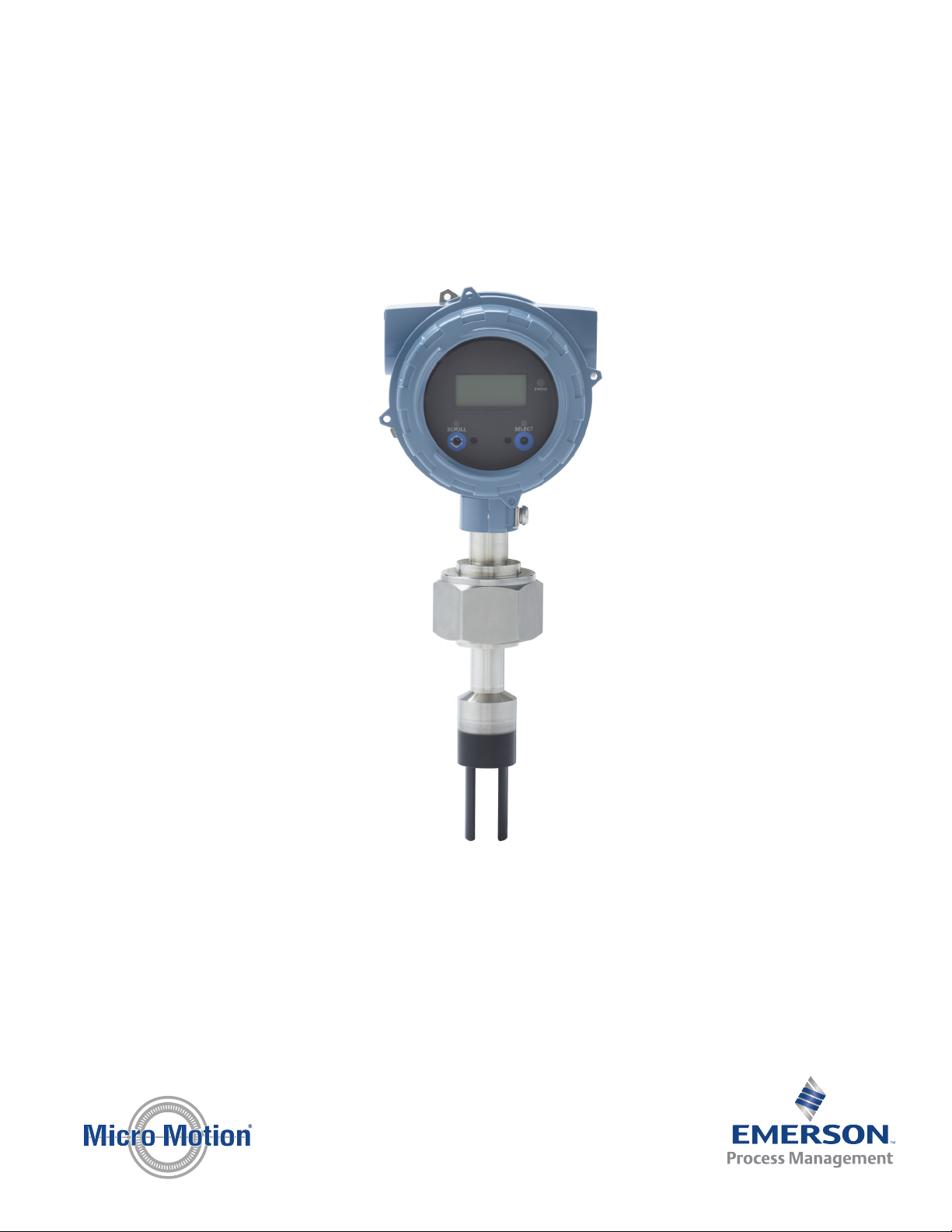
1. Power down the meter.
2. Using the strap wrench, loosen the grub screws and remove the transmitter end-
cap.
Transmitter with end-cap removedFigure 3-1:
A. Transmitter end‐cap
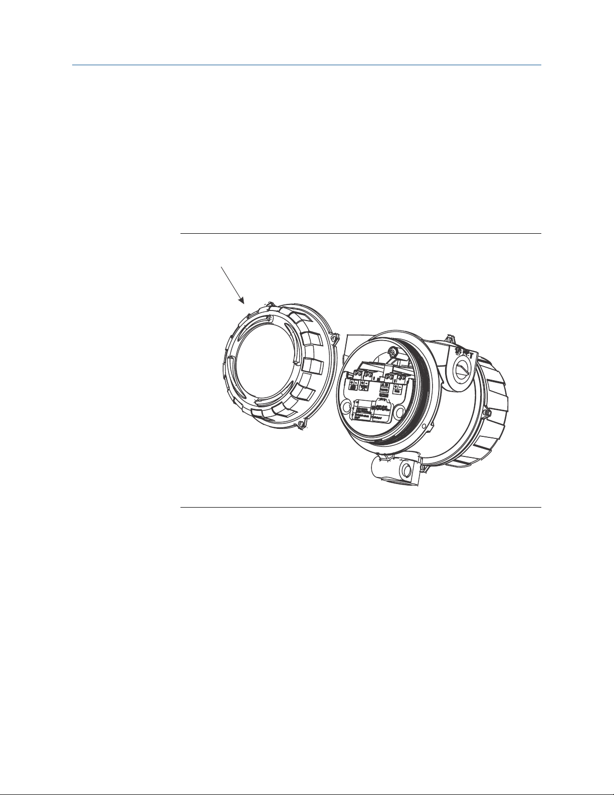
3. Using the hex key, remove the safety spacer.
12 Micro Motion® Fork Viscosity Meters (FVM)
Page 21
A
B
A
B
Introduction to configuration and commissioning
Transmitter with end-cap and safety spacer removedFigure 3-2:
A. Transmitter end‐cap
B. Safety spacer
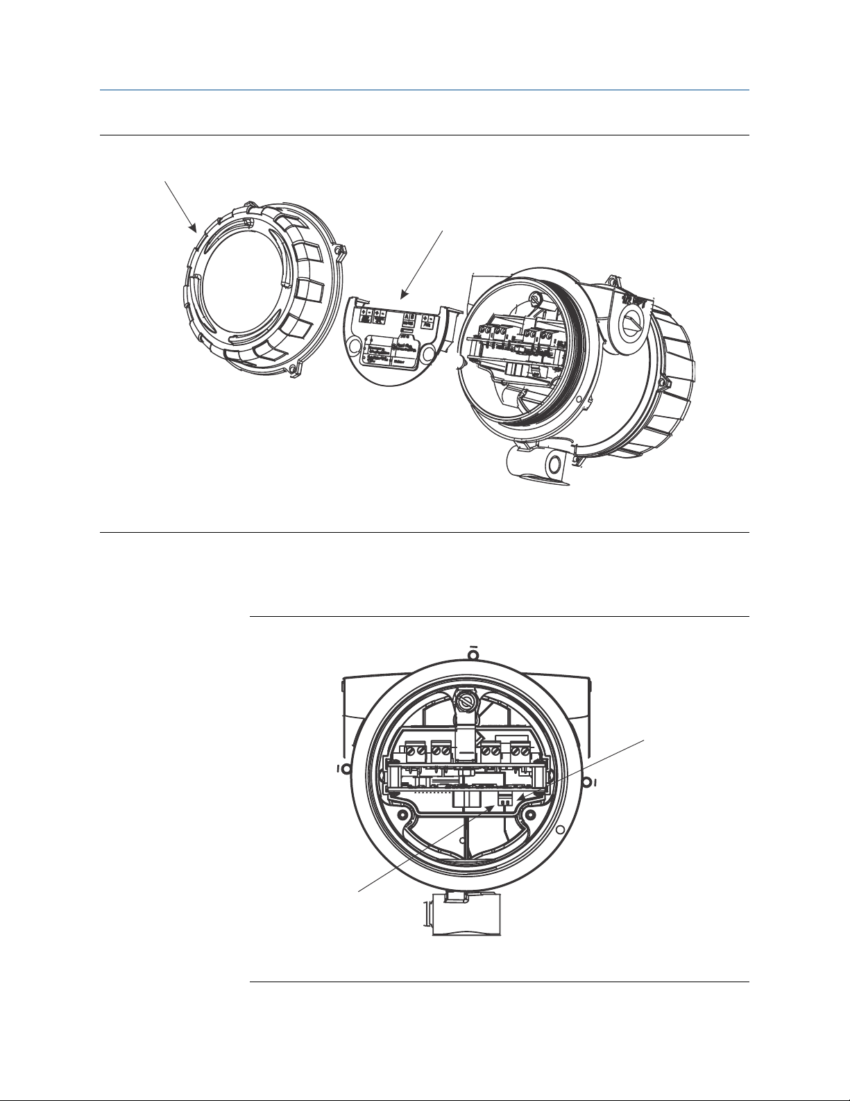
4. Move the HART security switch to the OFF position (up).
The HART security switch is the switch on the left.
HART security switchFigure 3-3:
A. HART security switch
B. Unused
Configuration and Use Manual 13
Page 22

Introduction to configuration and commissioning
5. Replace the safety spacer and end-cap.
6. Power up the meter.
3.4 Set the HART lock
If you plan to use a HART connection to configure the meter, you can lock out all other
HART masters. If you do this, other HART masters will be able to read data from the meter
but will not be able to write data to the meter.
Restrictions
• This feature is available only when you are using the Field Communicator or AMS.
• This feature requires HART 7.
Procedure
1. Choose Configure > Manual Setup > Security > Lock/Unlock Device.
2. If you are locking the meter, set Lock Option as desired.
Option Description
Permanent Only the current HART master can make changes to the device. The device will
remain locked until manually unlocked by a HART master. The HART master can
also change Lock Option to Temporary.
Temporary Only the current HART master can make changes to the device. The device will
remain locked until manually unlocked by a HART master, or a power-cycle or
device reset is performed. The HART master can also change Lock Option to Perma-
nent.
Lock All No HART masters are allowed to make changes to the configuration. Before
changing Lock Option to Permanent or Temporary, the device must be unlocked. Any
HART master can be used to unlock the device.
Postrequisites
To avoid confusion or difficulties at a later date, ensure that the meter is unlocked after
you have completed your tasks.
3.5 Restore the factory configuration
Display Not available
ProLink III Device Tools > Configuration Transfer > Restore Factory Configuration
Field Communicator Service Tools > Maintenance > Reset/Restore > Restore Factory Configuration
14 Micro Motion® Fork Viscosity Meters (FVM)
Page 23

Introduction to configuration and commissioning
Overview
Restoring the factory configuration returns the transmitter to a known operational
configuration. This may be useful if you experience problems during configuration.
Tip
Restoring the factory configuration is not a common action. You may want to contact Micro Motion
to see if there is a preferred method to resolve any issues.
Configuration and Use Manual 15
Page 24

Introduction to configuration and commissioning
16 Micro Motion® Fork Viscosity Meters (FVM)
Page 25

Configure process measurement
4 Configure process measurement
Topics covered in this chapter:
• Verify the calibration factors
• Configure line viscosity measurement
• Configure line density measurement
• Configure temperature measurement
• Configure the pressure input
• Configure referred viscosity measurement
• Set up the API referral application
• Set up concentration measurement
• Set up flow rate measurement
4.1 Verify the calibration factors
Display Not available
ProLink III Device Tools > Calibration Data
Field Communicator Configure > Manual Setup > Calibration Factors
Overview
The calibration factors are used to adjust measurement for the unique traits of the sensor.
Your device was calibrated at the factory. However, you should verify that the calibration
factors that are configured in your device match the factory values.
Prerequisites
You will need the factory values for the calibration factors. These are provided in two
locations:
• The calibration certificate shipped with your meter
• The label inside the transmitter's end-cap
Important
If the transmitter is not the original component, do not use the values from the transmitter label.
Procedure
1. View the calibration factors that are stored in the device.
2. Compare them to the factory values.
• If the values match, no action is required.
Configuration and Use Manual 17
Page 26

Configure process measurement
• If the values do not match, contact Micro Motion customer service.
Related information
Sample calibration certificate
4.1.1 Calibration factors
The original calibration factors are obtained from factory calibration, and are unique to
each device. They are used to adjust measurements for the specific physical properties of
the device.
The calibration certificate contains several sets of factors:
Viscosity
calibration
coefficients
Density calibration
coefficients
Temperature
compensation
coefficients
Viscosity
compensation
coefficients
The calibration certificate also provides the results of the Known Density Verification
procedure that was performed at the factory.
For each calibration performed at the factory, the calibration certificate contains the data
used to calculate the calibration coefficients.
Related information
Define the relationship between viscosity and the response of your
sensor. Viscosity calibration is performed for one to four viscosity
ranges, depending on the purchase order: Ultra-Low, Low,
Medium, and High. The meter continuously monitors the line
viscosity reading and automatically switches to the appropriate
set of calibration factors.
Define the relationship between density and the response of your
sensor.
Adjust density measurement for the effect of temperature on
sensor response.
Adjust density measurement for the effect of viscosity on sensor
response. There is a set of viscosity compensation coefficients for
the Medium viscosity range, and a set for the High viscosity range.
The viscosity compensation coefficients are generated only if the
corresponding viscosity range is calibrated on your device.
Sample calibration certificate
4.2 Configure line viscosity measurement
The viscosity measurement parameters control how viscosity is measured and reported.
• Configure Viscosity Measurement Unit (Section 4.2.1)
• Configure Viscosity Damping (Section 4.2.2)
18 Micro Motion® Fork Viscosity Meters (FVM)
Page 27
4.2.1 Configure Viscosity Measurement Unit
Display OFF-LINE MAINT > OFF-LINE CONFG > UNITS > DYN/VISC
OFF-LINE MAINT > OFF-LINE CONFG > UNITS > KIN/VISC
ProLink III Device Tools > Configuration > Process Measurement > Line Viscosity
Field Communicator Configure > Manual Setup > Measurements > Viscosity
Overview
The default measurement unit for dynamic viscosity is cP (centiPoise). The default
measurement unit for kinematic viscosity is cSt (centiStoke). You can configure a special
measurement unit for dynamic viscosity and kinematic viscosity.
Procedure
Verify that the unit is set correctly for both dynamic viscosity and kinematic viscosity.
Define a special measurement unit for dynamic viscosity or kinematic viscosity
Configure process measurement
Display Not available
ProLink III Device Tools > Configuration > Process Measurement > Line Viscosity > Special Units
Field Communicator Configure > Manual Setup > Measurements > Optional Setup > Special Units
Overview
A special measurement unit is a user-defined unit of measure that allows you to report
process data in a unit that is not available in the transmitter. A special measurement unit is
calculated from an existing measurement unit using a conversion factor. You can define a
special measurement unit for dynamic viscosity, kinematic viscosity, or both.
Procedure
• To define a special unit for dynamic viscosity:
1. Calculate Dynamic Viscosity Special Unit Conversion Factor as follows:
a. x base units = y special units
b. Dynamic Viscosity Special Unit Conversion Factor = x ÷ y
2. Enter Dynamic Viscosity Special Unit Conversion Factor.
3. Set User-Defined Label to the name you want to use for the dynamic viscosity unit.
• To define a special unit for kinematic viscosity:
1. Calculate Kinematic Viscosity Special Unit Conversion Factor as follows:
a. x base units = y special units
Configuration and Use Manual 19
Page 28

Configure process measurement
b. Kinematic Viscosity Special Unit Conversion Factor = x ÷ y
2. Enter Kinematic Viscosity Special Unit Conversion Factor.
3. Set User-Defined Label to the name you want to use for the kinematic viscosity
unit.
The special measurement unit is stored in the transmitter. You can configure the
transmitter to use the special measurement unit at any time.
Example: Defining a special measurement unit for kinematic viscosity
You want to measure kinematic viscosity in Stokes rather than centiStokes.
1. Calculate Kinematic Viscosity Special Unit Conversion Factor: 1 ÷ 100
2. Set Kinematic Viscosity Special Unit Conversion Factor to .001.
3. Set User-Defined Label to Stokes.
4.2.2 Configure Viscosity Damping
Display Not available
ProLink III Device Tools > Configuration > Process Measurement > Line Viscosity > Line Viscosity Damping
Field Communicator Not available
Overview
Viscosity Damping controls the amount of damping that will be applied to the line viscosity
value. It affects both dynamic viscosity and kinematic viscosity measurement.
Damping is used to smooth out small, rapid fluctuations in process measurement. Damping
Value specifies the time period (in seconds) over which the transmitter will spread changes
in the process variable. At the end of the interval, the internal value will reflect 63% of the
change in the actual measured value.
Tip
Viscosity damping affects all process variables that are calculated from line viscosity.
Procedure
Set Viscosity Damping to the value you want to use.
The default value is 0 seconds. The range is 0 to 440 seconds.
Interaction between Viscosity Damping and Added Damping
When the mA output is configured to report either dynamic viscosity or kinematic
viscosity, both Viscosity Damping and Added Damping are applied to the reported viscosity
value.
20 Micro Motion® Fork Viscosity Meters (FVM)
Page 29

Configure process measurement
Viscosity Damping controls the rate of change in the value of the process variable in
transmitter memory. Added Damping controls the rate of change reported via the mA
output.
If mA Output Process Variable is set to Dynamic Viscosity or Kinematic Viscosity, and both Viscosity
Damping and Added Damping are set to non-zero values, viscosity damping is applied first,
and the added damping calculation is applied to the result of the first calculation. This
value is reported over the mA output.
Related information
Interaction between mA Output Damping and process variable damping
4.3 Configure line density measurement
• Configure Density Measurement Unit (Section 4.3.1)
• Configure Density Damping (Section 4.3.2)
• Configure Density Cutoff (Section 4.3.3)
• Configure two‐phase flow parameters (Section 4.3.4)
4.3.1 Configure Density Measurement Unit
Display OFF-LINE MAINT > OFF-LINE CONFG > UNITS > DENS
ProLink III Device Tools > Configuration > Process Measurement > Line Density > Density Unit
Field Communicator Configure > Manual Setup > Measurements > Density > Density Unit
Overview
Density Measurement Unit controls the measurement units that will be used in density
calculations and reporting.
Restriction
If the API referral application is enabled, you cannot change the density measurement unit here. The
density measurement unit is controlled by the API table selection.
Procedure
Set Density Measurement Unit to the option you want to use.
The default setting for Density Measurement Unit is g/cm3 (grams per cubic centimeter).
Related information
Set up the API referral application
Configuration and Use Manual 21
Page 30

Configure process measurement
Options for Density Measurement Unit
The transmitter provides a standard set of measurement units for Density Measurement Unit.
Different communications tools may use different labels.
Options for Density Measurement UnitTable 4-1:
Label
Unit description
Specific gravity
Grams per cubic centimeter G/CM3 g/cm3 g/Cucm
Grams per liter G/L g/l g/L
Grams per milliliter G/mL g/ml g/mL
Kilograms per liter KG/L kg/l kg/L
Kilograms per cubic meter KG/M3 kg/m3 kg/Cum
Pounds per U.S. gallon LB/GAL lbs/Usgal lb/gal
Pounds per cubic foot LB/CUF lbs/ft3 lb/Cuft
Pounds per cubic inch LB/CUI lbs/in3 lb/CuIn
Short ton per cubic yard ST/CUY sT/yd3 STon/Cuyd
Degrees API D API degAPI degAPI
Special unit SPECL special Spcl
(1) Non‐standard calculation. This value represents line density divided by the density of water at 60 °F.
(1)
Display ProLink III Field Communicator
SGU SGU SGU
Define a special measurement unit for density
Display Not available
ProLink III Device Tools > Configuration > Process Measurement > Line Density > Special Units
Field Communicator Configure > Manual Setup > Measurements > Special Units
Overview
A special measurement unit is a user-defined unit of measure that allows you to report
process data in a unit that is not available in the transmitter. A special measurement unit is
calculated from an existing measurement unit using a conversion factor.
Procedure
1. Specify Density Special Unit Base.
Density Special Unit Base is the existing density unit that the special unit will be based
on.
2. Calculate Density Special Unit Conversion Factor as follows:
22 Micro Motion® Fork Viscosity Meters (FVM)
Page 31

a. x base units = y special units
b. Density Special Unit Conversion Factor = x/y
3. Enter Density Special Unit Conversion Factor.
4. Set User-Defined Label to the name you want to use for the density unit.
The special measurement unit is stored in the transmitter. You can configure the
transmitter to use the special measurement unit at any time.
Example: Defining a special measurement unit for density
You want to measure density in ounces per cubic inch.
1. Set Density Special Unit Base to g/cm3.
2. Calculate Density Special Unit Conversion Factor: 1 g/cm3 = 0.578 oz/in3
3. Set Density Special Unit Conversion Factor to 0.578.
4. Set User-Defined Label to oz/in3.
4.3.2 Configure Density Damping
Configure process measurement
Display Not available
ProLink III Device Tools > Configuration > Process Measurement > Line Density > Density Damping
Field Communicator Configure > Manual Setup > Measurements > Density > Density Damping
Overview
Density Damping controls the amount of damping that will be applied to the line density
value.
Damping is used to smooth out small, rapid fluctuations in process measurement. Damping
Value specifies the time period (in seconds) over which the transmitter will spread changes
in the process variable. At the end of the interval, the internal value will reflect 63% of the
change in the actual measured value.
Tip
Density damping affects all process variables that are calculated from line density.
Procedure
Set Density Damping to the value you want to use.
The default value is 0 seconds. The range is 0 to 60 seconds.
Interaction between Density Damping and Added Damping
When the mA output is configured to report density, both Density Damping and Added
Damping are applied to the reported density value.
Configuration and Use Manual 23
Page 32

Configure process measurement
Density Damping controls the rate of change in the value of the process variable in
transmitter memory. Added Damping controls the rate of change reported via the mA
output.
If mA Output Process Variable is set to Density, and both Density Damping and Added Damping are
set to non-zero values, density damping is applied first, and the added damping
calculation is applied to the result of the first calculation. This value is reported over the
mA output.
Related information
Interaction between mA Output Damping and process variable damping
4.3.3 Configure Density Cutoff
Display Not available
ProLink III Device Tools > Configuration > Process Measurement > Line Density > Density Cutoff Low
Field Communicator Configure > Manual Setup > Measurements > Density > Density Cutoff
Overview
Density Cutoff Low specifies the lowest density value that will be reported as measured. All
density values below this cutoff will be reported as 0.
Procedure
Set Density Cutoff Low to the value you want to use.
The default value is 0.2 g/cm³. The range is 0.0 g/cm³ to 0.5 g/cm³.
4.3.4 Configure two-phase flow parameters
Display Not available
ProLink III Device Tools > Configuration > Process Measurement > Line Density
Field Communicator Configure > Manual Setup > Measurements > Density
Overview
The two-phase flow parameters control how the transmitter detects and reports twophase flow (gas in a liquid process or liquid in a gas process).
Note
Two-phase flow is sometimes referred to as slug flow.
24 Micro Motion® Fork Viscosity Meters (FVM)
Page 33

Configure process measurement
Procedure
1. Set Two-Phase Flow Low Limit to the lowest density value that is considered normal in
your process.
Values below this will cause the transmitter to post Alert A105 ().
Tip
Gas entrainment can cause your process density to drop temporarily. To reduce the
occurrence of two-phase flow alerts that are not significant to your process, set Two-Phase Flow
Low Limit slightly below your expected lowest process density.
You must enter Two-Phase Flow Low Limit in g/cm³, even if you configured another unit
for density measurement.
2. Set Two-Phase Flow High Limit to the highest density value that is considered normal in
your process.
Values above this will cause the transmitter to post Alert A105 (Two-Phase Flow).
Tip
To reduce the occurrence of two-phase flow alerts that are not significant to your process, set
Two-Phase Flow High Limit slightly above your expected highest process density.
You must enter Two-Phase Flow High Limit in g/cm³, even if you configured another
unit for density measurement.
3. Set Two-Phase Flow Timeout to the number of seconds that the transmitter will wait for
a two-phase flow condition to clear before posting the alert.
The default value for Two-Phase Flow Timeout is 0.0 seconds, meaning that the alert
will be posted immediately. The range is 0.0 to 60.0 seconds.
Detecting and reporting two-phase flow
Two-phase flow (gas in a liquid process or liquid in a gas process) can cause a variety of
process control issues. By configuring the two-phase flow parameters appropriately for
your application, you can detect process conditions that require correction.
Tip
To decrease the occurrence of two-phase flow alerts, lower Two-Phase Flow Low Limit or raise Two-Phase
Flow High Limit.
A two-phase flow condition occurs whenever the measured density goes below Two-Phase
Flow Low Limit or above Two-Phase Flow High Limit. If this occurs:
• A two-phase flow alert is posted to the active alert log.
• Line density is held at its last pre‐alert value for the number of seconds configured in
Two-Phase Flow Timeout.
If the two-phase flow condition clears before Two-Phase Flow Timeout expires:
Configuration and Use Manual 25
Page 34

Configure process measurement
• Line density reverts to actual process density.
• The two-phase flow alert is deactivated, but remains in the active alert log until it is
acknowledged.
If the two-phase flow condition does not clear before Two-Phase Flow Timeout expires, line
density reverts to actual process density, but the two-phase flow alert remains active.
If Two-Phase Flow Timeout is set to 0.0 seconds, two-phase flow will cause a two-phase flow
alert but will have no effect on how the meter measures or reports line density.
4.4 Configure temperature measurement
The temperature measurement parameters control how temperature data from the
sensor is reported.
• Configure Temperature Measurement Unit (Section 4.4.1)
• Configure Temperature Damping (Section 4.4.2)
• Configure Temperature Input (Section 4.4.3)
4.4.1 Configure Temperature Measurement Unit
Display OFF-LINE MAINT > OFF-LINE CONFG > UNITS > TEMP
ProLink III Device Tools > Configuration > Process Measurement > Line Temperature > Temperature Unit
Field Communicator Configure > Manual Setup > Measurements > Temperature > Temperature Unit
Overview
Temperature Measurement Unit specifies the unit that will be used for temperature
measurement.
Restriction
If the API referral application is enabled, the API table selection automatically sets the temperature
measurement unit. Configure the API referral application first, then change the temperature
measurement unit if desired.
Procedure
Set Temperature Measurement Unit to the option you want to use.
The default setting is Degrees Celsius.
Related information
Set up the API referral application
26 Micro Motion® Fork Viscosity Meters (FVM)
Page 35

Options for Temperature Measurement Unit
The transmitter provides a standard set of units for Temperature Measurement Unit. Different
communications tools may use different labels for the units.
Options for Temperature Measurement UnitTable 4-2:
Unit description
Degrees Celsius °C °C degC
Degrees Fahrenheit °F °F degF
Degrees Rankine °R °R degR
Kelvin °K °K Kelvin
Display ProLink III
4.4.2 Configure Temperature Damping
Configure process measurement
Label
Field Communicator
Display Not available
ProLink III Device Tools > Configuration > Process Measurement > Line Temperature > Temperature Damping
Field Communicator Configure > Manual Setup > Measurements > Temperature > Temperature Damping
Overview
Temperature Damping controls the amount of damping that will be applied to the line
temperature value, when the on-board temperature data is used (RTD).
Damping is used to smooth out small, rapid fluctuations in process measurement. Damping
Value specifies the time period (in seconds) over which the transmitter will spread changes
in the process variable. At the end of the interval, the internal value will reflect 63% of the
change in the actual measured value.
Tip
Temperature Damping affects all process variables, compensations, and corrections that use
temperature data from the sensor.
Procedure
Enter the value you want to use for Temperature Damping.
The default value is 4.8 seconds.
Tips
• A high damping value makes the process variable appear smoother because the reported value
changes slowly.
Configuration and Use Manual 27
Page 36

Configure process measurement
• A low damping value makes the process variable appear more erratic because the reported value
changes more quickly.
• Whenever the damping value is non-zero, the reported measurement will lag the actual
measurement because the reported value is being averaged over time.
• In general, lower damping values are preferable because there is less chance of data loss, and less
lag time between the actual measurement and the reported value.
The value you enter is automatically rounded down to the nearest valid value.
4.4.3 Configure Temperature Input
Temperature data from the on-board temperature sensor (RTD) is always available. You
can set up an external temperature device and use external temperature data if you want
to.
• Configure Temperature Input using ProLink III
• Configure Temperature Input using the Field Communicator
Configure Temperature Input using ProLink III
ProLink III Device Tools > Configuration > Process Measurement > Line Temperature > Line Temperature Source
Overview
Temperature data from the on-board temperature sensor (RTD) is always available. You
can set up an external temperature device and use external temperature data if you want
to.
Tip
Use an external device only if it is more accurate than the internal RTD.
Important
Line temperature data is used in several different measurements and calculations. It is possible to
use the internal RTD temperature in some areas and an external temperature in others. The
transmitter stores the internal RTD temperature and the external temperature separately. However,
the transmitter stores only one alternate temperature value, which may be either an external
temperature or the configured fixed value. Accordingly, if you set up polling for temperature in one
area, and digital communications in another, and configure a fixed temperature value in a third, the
fixed value will be overwritten by polling and digital communications, and polling and digital
communications will overwrite each other.
Procedure
Choose the method to be used to supply temperature data, and perform the required
setup.
28 Micro Motion® Fork Viscosity Meters (FVM)
Page 37

Option Description Setup
Internal RTD temperature data
Polling The meter polls an external de-
Digital communications
Temperature data from the onboard temperature sensor
(RTD) is used.
vice for temperature data. This
data will be available in addition to the internal RTD temperature data.
A host writes temperature data
to the meter at appropriate intervals. This data will be available in addition to the internal
RTD temperature data.
a. Set Line Temperature Source to Internal RTD.
b. Click Apply.
a. Set Line Temperature Source to Poll for External Value.
b. Set Polling Slot to an available slot.
c. Set Polling Control to Poll as Primary or Poll as Secondary.
Option Description
Poll as Primary No other HART masters will be on the
Poll as Secondary Other HART masters will be on the net-
d. Set External Device Tag to the HART tag of the temperature
device.
e. Click Apply.
a. Set Line Temperature Source to Fixed Value or Digital Communica-
tions.
b. Click Apply.
c. Perform the necessary host programming and communica-
tions setup to write temperature data to the meter at appro-
priate intervals.
Configure process measurement
network. The Field Communicator is not
a HART master.
work. The Field Communicator is not a
HART master.
Postrequisites
If you are using external temperature data, verify the external temperature value displayed
in the Inputs group on the ProLink III main window .
Need help? If the value is not correct:
• Ensure that the external device and the meter are using the same measurement unit.
• For polling:
- Verify the wiring between the meter and the external device.
- Verify the HART tag of the external device.
• For digital communications:
- Verify that the host has access to the required data.
- Verify that the host is writing to the correct register in memory, using the correct data
type.
• If necessary, apply an offset.
Configuration and Use Manual 29
Page 38

Configure process measurement
Configure Temperature Input using the Field Communicator
Field Communicator Configure > Manual Setup > Measurements > External Inputs > Temperature
Overview
Temperature data from the on-board temperature sensor (RTD) is always available. You
can set up an external temperature device and use external temperature data if you want
to.
Tip
Use an external device only if it is more accurate than the internal RTD.
Important
Line temperature data is used in several different measurements and calculations. It is possible to
use the internal RTD temperature in some areas and an external temperature in others. The
transmitter stores the internal RTD temperature and the external temperature separately. However,
the transmitter stores only one alternate temperature value, which may be either an external
temperature or the configured fixed value. Accordingly, if you set up polling for temperature in one
area, and digital communications in another, and configure a fixed temperature value in a third, the
fixed value will be overwritten by polling and digital communications, and polling and digital
communications will overwrite each other.
Procedure
Choose the method to be used to supply temperature data, and perform the required
setup.
Method Description Setup
Internal RTD temperature data
Temperature data from the onboard temperature sensor
(RTD) is used.
a. Choose Configure > Manual Setup > Measurements > Optional Setup
> External Inputs > Temperature.
b. Set External Temperature for Viscosity to Disable.
30 Micro Motion® Fork Viscosity Meters (FVM)
Page 39

Method Description Setup
Polling The meter polls an external de-
vice for temperature data. This
data will be available in addition to the internal RTD temperature data.
Digital communications
A host writes temperature data
to the meter at appropriate intervals. This data will be available in addition to the internal
RTD temperature data.
a. Choose Configure > Manual Setup > Measurements > Optional Setup
> External Inputs > Temperature.
b. Set External Temperature for Viscosity to Enable.
c. Choose Configure > Manual Setup > Inputs/Outputs > External Device
Polling.
d. Choose an unused polling slot.
e. Set Poll Control to Poll as Primary or Poll as Secondary.
Option Description
Poll as Primary No other HART masters will be on the
Poll as Secondary Other HART masters will be on the net-
f. Set External Device Tag to the HART tag of the external tem-
perature device.
g. Set Polled Variable to Temperature.
a. Choose Configure > Manual Setup > Measurements > Optional Setup
> External Inputs > Temperature.
b. Set External Temperature for Viscosity to Enable.
c. Perform the necessary host programming and communica-
tions setup to write temperature data to the meter at appro-
priate intervals.
Configure process measurement
network. The Field Communicator is not
a HART master.
work. The Field Communicator is not a
HART master.
Postrequisites
To view the current external temperature value, choose Service Tools > Variables > External
Variables. Verify that the value is correct.
Need help? If the value is not correct:
• Ensure that the external device and the meter are using the same measurement unit.
• For polling:
- Verify the wiring between the meter and the external device.
- Verify the HART tag of the external device.
• For digital communications:
- Verify that the host has access to the required data.
- Verify that the host is writing to the correct register in memory, using the correct data
type.
• If necessary, apply an offset.
Configuration and Use Manual 31
Page 40

Configure process measurement
4.5 Configure the pressure input
Pressure data is required for several different measurements. The meter does not measure
pressure. There are several different methods to obtain pressure data.
• Configure the pressure input using ProLink III (Section 4.5.1)
• Configure the pressure input using the Field Communicator (Section 4.5.2)
4.5.1 Configure the pressure input using ProLink III
ProLink III Device Tools > Configuration > Process Measurement > Line Pressure
Overview
Pressure data is required for several different measurements. There are several different
methods to obtain pressure data.
Tip
A fixed pressure value is not recommended. A fixed pressure value may produce inaccurate process
data.
Procedure
1. Choose Device Tools > Configuration > Process Measurement > Line Pressure.
2. Set Pressure Unit to the unit used by the external pressure device.
Restriction
If the API referral application is enabled, the API table selection automatically sets the
pressure measurement unit. Configure the API referral application first, then change the
pressure measurement unit if necessary.
3. Choose the method you will use to supply pressure data, and perform the required
setup.
Option Description Setup
Polling The meter polls an external de-
vice for pressure data.
Digital communications
A host writes pressure data to
the meter at appropriate intervals.
a. Set Line Pressure Source to Poll for External Value.
b. Set Polling Slot to an available slot.
c. Set Polling Control to Poll as Primary or Poll as Secondary.
d. Set External Device Tag to the HART tag of the temperature
device.
a. Set Line Pressure Source to Fixed Value or Digital Communications.
b. Perform the necessary host programming and communica-
tions setup to write pressure data to the meter at appropriate intervals.
32 Micro Motion® Fork Viscosity Meters (FVM)
Page 41

Configure process measurement
Postrequisites
The current pressure value is displayed in the External Pressure field. Verify that the value is
correct.
Need help? If the value is not correct:
• Ensure that the external device and the meter are using the same measurement unit.
• For polling:
- Verify the wiring between the meter and the external device.
- Verify the HART tag of the external device.
• For digital communications:
- Verify that the host has access to the required data.
- Verify that the host is writing to the correct register in memory, using the correct data
type.
• If necessary, apply an offset.
Related information
Set up the API referral application
4.5.2 Configure the pressure input using the Field Communicator
Pressure data is required for several different measurements. The meter does not measure
pressure. There are several different methods to obtain pressure data.
Prerequisites
You must be using gauge pressure.
Procedure
1. Choose Configure > Manual Setup > Measurements > External Inputs > Pressure.
2. Set Pressure Input to Enable.
3. Set Pressure Unit to the unit used by the external pressure device.
Restriction
If the API referral application is enabled, the API table selection automatically sets the
pressure measurement unit. Configure the API referral application first, then change the
pressure measurement unit if necessary.
4. Set up the pressure input.
a. Choose Configure > Manual Setup > Inputs/Outputs > External Device Polling.
b. Choose an unused polling slot.
c. Set Polling Control to Poll as Primary or Poll as Secondary.
Configuration and Use Manual 33
Page 42

Configure process measurement
Postrequisites
To view the current pressure value, choose Service Tools > Variables > External Variables. Verify
that the value is correct.
Need help? If the value is not correct:
• Ensure that the external device and the meter are using the same measurement unit.
• For polling:
• For digital communications:
• If necessary, apply an offset.
Option Description
Poll as Primary No other HART masters will be on the network. The
Field Communicator is not a HART master.
Poll as Secondary Other HART masters will be on the network. The
Field Communicator is not a HART master.
d. Set External Device Tag to the HART tag of the external pressure device.
e. Set Polled Variable to Pressure.
- Verify the wiring between the meter and the external device.
- Verify the HART tag of the external device.
- Verify that the host has access to the required data.
- Verify that the host is writing to the correct register in memory, using the correct data
type.
Related information
Set up the API referral application
4.5.3 Options for Pressure Measurement Unit
The transmitter provides a standard set of measurement units for Pressure Measurement Unit.
Different communications tools may use different labels for the units. In most
applications, Pressure Measurement Unit should be set to match the pressure measurement
unit used by the remote device.
Options for Pressure Measurement UnitTable 4-3:
Label
Unit description
Feet water @ 68 °F FTH2O Ft Water @ 68°F ftH2O
Inches water @ 4 °C INW4C In Water @ 4°C inH2O @4DegC
Inches water @ 60 °F INW60 In Water @ 60°F inH2O @60DegF
Inches water @ 68 °F INH2O In Water @ 68°F inH2O
Display ProLink III Field Communicator
34 Micro Motion® Fork Viscosity Meters (FVM)
Page 43

Configure process measurement
Options for Pressure Measurement Unit (continued)Table 4-3:
Label
Unit description
Millimeters water @ 4 °C mmW4C mm Water @ 4°C mmH2O @4DegC
Millimeters water @ 68 °F mmH2O mm Water @ 68°F mmH2O
Millimeters mercury @ 0 °C mmHG mm Mercury @ 0°C mmHg
Inches mercury @ 0 °C INHG In Mercury @ 0°C inHG
Pounds per square inch PSI PSI psi
Bar BAR bar bar
Millibar mBAR millibar mbar
Grams per square centimeter G/SCM g/cm2 g/Sqcm
Kilograms per square centimeter KG/SCM kg/cm2 kg/Sqcm
Pascals PA pascals Pa
Kilopascals KPA Kilopascals kPa
Megapascals MPA Megapascals MPa
Torr @ 0 °C TORR Torr @ 0°C torr
Atmospheres ATM atms atms
Display ProLink III Field Communicator
4.6 Configure referred viscosity measurement
Referred viscosity is line viscosity corrected to a reference temperature. In other words, this
is the viscosity that the device would report if the line temperature matched the reference
temperature.
Three methods are available to calculate referred viscosity. These methods are described
in the following table.
Configuration methods for referred viscosityTable 4-4:
Referred viscosity calculation
method Description
ASTM D341 Single-Curve • Based on ASTM D341 standards
• Applicable only to petroleum products
• Used when the meter will measure only one process fluid
ASTM D341 Multi-Curve • Based on ASTM D341 standards
• Applicable only to petroleum products
• Supports measurement of two to eight process fluids from
one configuration
Configuration and Use Manual 35
Page 44

Configure process measurement
Configuration methods for referred viscosity (continued)Table 4-4:
Referred viscosity calculation
method Description
Matrix Referral • Not based on ASTM D341 standards
• Applicable to all process fluids
• Supports measurement of two to six process fluids from one
configuration
4.6.1 Configure referred viscosity measurement, ASTM D341 Single-Curve method
Referred viscosity is line viscosity corrected to a reference temperature. In other words, this
is the viscosity that the device would report if the line temperature matched the reference
temperature. The ASTM D341 single-curve method is used only with petroleum products.
It is used when the meter will measure only one process fluid.
• Configure referred viscosity measurement, ASTM D341 Single‐Curve method, using
ProLink III
• Configure referred viscosity measurement, ASTM D341 Single‐Curve method, using the
Field Communicator
Configure referred viscosity measurement, ASTM D341 Single-Curve method, using ProLink III
ProLink III Device Tools > Configuration > Process Measurement > Referred Viscosity
Overview
Referred viscosity is line viscosity corrected to a reference temperature. In other words, this
is the viscosity that the device would report if the line temperature matched the reference
temperature. The ASTM D341 single-curve method is used only with petroleum products.
It is used when the meter will measure only one process fluid.
Important
Use the ASTM D341 Single-Curve method only with petroleum products.
Prerequisites
You must know the viscosity of your process fluid at two temperatures.
Procedure
1. Choose Device Tools > Configuration > Process Measurement > Referred Viscosity.
2. Set Referred Viscosity Method to ASTM D341 Single-Curve, and click Apply to refresh the
screen.
36 Micro Motion® Fork Viscosity Meters (FVM)
Page 45

Configure process measurement
3. Define the curve.
a. Enter two temperature values, one in Lower Temperature and one in Higher
Temperature.
Enter the temperature in the currently configured temperature unit.
b. For each temperature, enter the viscosity of your process fluid at that
temperature.
Important
You must enter the viscosity in cSt (centistokes). If cP is displayed rather than cSt, click
Apply to refresh the screen.
4. Enter two reference temperatures.
The first reference temperature will be used to calculate the Referred Viscosity
process variable. The second reference temperature will be used to calculate the
Referred Viscosity (Secondary) process variable. They do not need to be within the
temperature range of the curve.
5. Choose the method to be used to supply temperature data, and perform the
required setup.
Option Description Setup
Internal RTD temperature data
Polling The meter polls an external de-
Temperature data from the onboard temperature sensor
(RTD) is used.
vice for temperature data. This
data will be available in addition to the internal RTD temperature data.
a. Set Line Temperature Source to Internal RTD.
b. Click Apply.
a. Set Line Temperature Source to Poll for External Value.
b. Set Polling Slot to an available slot.
c. Set Polling Control to Poll as Primary or Poll as Secondary.
Option Description
Poll as Primary No other HART masters will be on the
Poll as Secondary Other HART masters will be on the net-
d. Set External Device Tag to the HART tag of the temperature
device.
e. Click Apply.
network. The Field Communicator is not
a HART master.
work. The Field Communicator is not a
HART master.
Configuration and Use Manual 37
Page 46

Configure process measurement
Option Description Setup
Digital communications
A host writes temperature data
to the meter at appropriate intervals. This data will be available in addition to the internal
RTD temperature data.
a. Set Line Temperature Source to Fixed Value or Digital Communica-
b. Click Apply.
c. Perform the necessary host programming and communica-
6. Verify that your temperature setup is being applied as intended.
a. Choose Device Tools > Configuration > I/O > Inputs > External Inputs.
b. Check or check the checkboxes as desired.
If a checkbox is checked, the internal RTD temperature is used for that
measurement or calculation. If a checkbox is unchecked, the external
temperature is used.
Postrequisites
If you are using external temperature data, verify the external temperature value displayed
in the Inputs group on the ProLink III main window .
tions.
tions setup to write temperature data to the meter at appropriate intervals.
Need help? If the value is not correct:
• Ensure that the external device and the meter are using the same measurement unit.
• For polling:
- Verify the wiring between the meter and the external device.
- Verify the HART tag of the external device.
• For digital communications:
- Verify that the host has access to the required data.
- Verify that the host is writing to the correct register in memory, using the correct data
type.
• If necessary, apply an offset.
Configure referred viscosity measurement, ASTM D341 Single-Curve method, using the Field Communicator
Field Communicator Configure > Manual Setup > Measurements > Optional Setup > Referred Viscosity
Overview
Referred viscosity is line viscosity corrected to a reference temperature. In other words, this
is the viscosity that the device would report if the line temperature matched the reference
temperature. The ASTM D341 single-curve method is used only with petroleum products.
It is used when the meter will measure only one process fluid.
38 Micro Motion® Fork Viscosity Meters (FVM)
Page 47

Configure process measurement
Important
Use the ASTM D341 Single-Curve method only with petroleum products.
Prerequisites
You must know the viscosity of your process fluid at two temperatures.
Procedure
1. Choose Configure > Manual Setup > Measurements > Optional Setup > Referred Viscosity.
2. Set Referred Viscosity Calculation Method to ASTM D341 Single.
3. Choose ASTM D341 Single.
4. Define the curve.
a. Enter two temperature values, one in Temperature 1 and one in Temperature 2.
Enter the temperature in the currently configured temperature unit.
b. For each temperature, enter the viscosity of your process fluid at that
temperature.
Important
You must enter the viscosity in cSt (centistokes). If cP is displayed rather than cSt, send
data to the transmitter to refresh the display.
5. Enter two reference temperatures.
The first reference temperature will be used to calculate the Referred Viscosity
process variable. The second reference temperature will be used to calculate the
Referred Viscosity (Secondary) process variable. They do not need to be within the
temperature range of the curve.
6. Choose the method to be used to supply temperature data, and perform the
required setup.
Method Description Setup
Internal RTD temperature data
Temperature data from the onboard temperature sensor
(RTD) is used.
a. Choose Configure > Manual Setup > Measurements > Optional Setup
> External Inputs > Temperature.
b. Set External Temperature for Viscosity to Disable.
Configuration and Use Manual 39
Page 48

Configure process measurement
Method Description Setup
Polling The meter polls an external de-
vice for temperature data. This
data will be available in addition to the internal RTD temperature data.
Digital communications
A host writes temperature data
to the meter at appropriate intervals. This data will be available in addition to the internal
RTD temperature data.
a. Choose Configure > Manual Setup > Measurements > Optional Setup
b. Set External Temperature for Viscosity to Enable.
c. Choose Configure > Manual Setup > Inputs/Outputs > External Device
d. Choose an unused polling slot.
e. Set Poll Control to Poll as Primary or Poll as Secondary.
Option Description
Poll as Primary No other HART masters will be on the
Poll as Secondary Other HART masters will be on the net-
f. Set External Device Tag to the HART tag of the external tem-
g. Set Polled Variable to Temperature.
a. Choose Configure > Manual Setup > Measurements > Optional Setup
b. Set External Temperature for Viscosity to Enable.
c. Perform the necessary host programming and communica-
> External Inputs > Temperature.
Polling.
network. The Field Communicator is not
a HART master.
work. The Field Communicator is not a
HART master.
perature device.
> External Inputs > Temperature.
tions setup to write temperature data to the meter at appropriate intervals.
Postrequisites
To view the current external temperature value, choose Service Tools > Variables > External
Variables. Verify that the value is correct.
Need help? If the value is not correct:
• Ensure that the external device and the meter are using the same measurement unit.
• For polling:
- Verify the wiring between the meter and the external device.
- Verify the HART tag of the external device.
• For digital communications:
- Verify that the host has access to the required data.
- Verify that the host is writing to the correct register in memory, using the correct data
type.
• If necessary, apply an offset.
40 Micro Motion® Fork Viscosity Meters (FVM)
Page 49

Configure process measurement
4.6.2 Configure referred viscosity measurement, ASTM D341 Multi-Curve method
Referred viscosity is line viscosity corrected to a reference temperature. In other words, this
is the viscosity that the device would report if the line temperature matched the reference
temperature. The ASTM D341 multi-curve method is used only with petroleum products.
It is used when the meter will measure two to eight process fluids.
• Configure referred viscosity measurement, ASTM D341 Multi‐Curve method, using
ProLink III
• Configure referred viscosity measurement, ASTM D341 Multi‐Curve method, using the
Field Communicator
Configure referred viscosity measurement, ASTM D341 Multi-Curve method, using ProLink III
ProLink III Device Tools > Configuration > Process Measurement > Referred Viscosity
Overview
Referred viscosity is line viscosity corrected to a reference temperature. In other words, this
is the viscosity that the device would report if the line temperature matched the reference
temperature. The ASTM D341 multi-curve method is used only with petroleum products.
It is used when the meter will measure two to eight process fluids.
You can set up referred viscosity calculations for up to eight process fluids.
Important
Use the ASTM D341 Multi-Curve method only with petroleum products.
Prerequisites
For each process fluid, you must know its viscosity at two temperatures.
Procedure
1. Choose Device Tools > Configuration > Process Measurement > Referred Viscosity.
2. Set Referred Viscosity Method to ASTM D341 Multi-Curve, and click Apply to refresh the
screen.
3. Define the curve for each process fluid.
a. Enter two temperature values, one in Lower Temperature and one in Higher
Temperature.
Enter the temperature in the currently configured temperature unit.
b. For each temperature, enter the viscosity of your process fluid at that
temperature.
Configuration and Use Manual 41
Page 50

Configure process measurement
Important
You must enter the viscosity in cSt (centistokes). If cP is displayed rather than cSt, click
Apply to refresh the screen.
4. Enter two reference temperatures.
The first reference temperature will be used to calculate the Referred Viscosity
process variable. The second reference temperature will be used to calculate the
Referred Viscosity (Secondary) process variable. They do not need to be within the
temperature range of the curve.
5. Choose the method to be used to supply temperature data, and perform the
required setup.
Option Description Setup
Internal RTD temperature data
Polling The meter polls an external de-
Temperature data from the onboard temperature sensor
(RTD) is used.
vice for temperature data. This
data will be available in addition to the internal RTD temperature data.
a. Set Line Temperature Source to Internal RTD.
b. Click Apply.
a. Set Line Temperature Source to Poll for External Value.
b. Set Polling Slot to an available slot.
c. Set Polling Control to Poll as Primary or Poll as Secondary.
Option Description
Poll as Primary No other HART masters will be on the
Poll as Secondary Other HART masters will be on the net-
network. The Field Communicator is not
a HART master.
work. The Field Communicator is not a
HART master.
d. Set External Device Tag to the HART tag of the temperature
device.
e. Click Apply.
Digital communications
A host writes temperature data
to the meter at appropriate intervals. This data will be available in addition to the internal
RTD temperature data.
a. Set Line Temperature Source to Fixed Value or Digital Communica-
tions.
b. Click Apply.
c. Perform the necessary host programming and communica-
tions setup to write temperature data to the meter at appro-
priate intervals.
6. Verify that your temperature setup is being applied as intended.
a. Choose Device Tools > Configuration > I/O > Inputs > External Inputs.
b. Check or check the checkboxes as desired.
42 Micro Motion® Fork Viscosity Meters (FVM)
Page 51

Configure process measurement
If a checkbox is checked, the internal RTD temperature is used for that
measurement or calculation. If a checkbox is unchecked, the external
temperature is used.
Postrequisites
If you are using external temperature data, verify the external temperature value displayed
in the Inputs group on the ProLink III main window .
Need help? If the value is not correct:
• Ensure that the external device and the meter are using the same measurement unit.
• For polling:
- Verify the wiring between the meter and the external device.
- Verify the HART tag of the external device.
• For digital communications:
- Verify that the host has access to the required data.
- Verify that the host is writing to the correct register in memory, using the correct data
type.
• If necessary, apply an offset.
Configure referred viscosity measurement, ASTM D341 Multi-Curve method, using the Field Communicator
Field Communicator Configure > Manual Setup > Measurements > Optional Setup > Referred Viscosity
Overview
Referred viscosity is line viscosity corrected to a reference temperature. In other words, this
is the viscosity that the device would report if the line temperature matched the reference
temperature. The ASTM D341 multi-curve method is used only with petroleum products.
It is used when the meter will measure two to eight process fluids.
You can set up referred viscosity calculations for up to eight process fluids.
Important
Use the ASTM D341 Multi-Curve method only with petroleum products.
Prerequisites
For each process fluid, you must know its viscosity at two temperatures.
Procedure
1. Choose Configure > Manual Setup > Measurements > Optional Setup > Referred Viscosity.
2. Set Referred Viscosity Calculation Method to ASTM D341 Multi.
3. Choose ASTM D341 Multi.
Configuration and Use Manual 43
Page 52

Configure process measurement
4. Define the curve for each process fluid.
5. Enter two reference temperatures.
a. Choose Viscosity at Specific Temp.
b. Choose Fluid 1.
c. Enter two temperature values, one in Temperature 1 and one in Temperature 2.
Enter the temperature in the currently configured temperature unit.
d. For each temperature, enter the viscosity of your process fluid at that
temperature.
Important
You must enter the viscosity in cSt (centistokes). If cP is displayed rather than cSt, send
data to the transmitter to refresh the display.
e. Press the back arrow and repeat this step until curves have been defined for all
fluids.
The first reference temperature will be used to calculate the Referred Viscosity
process variable. The second reference temperature will be used to calculate the
Referred Viscosity (Secondary) process variable. They do not need to be within the
temperature range of the curve.
6. Choose the method to be used to supply temperature data, and perform the
required setup.
Method Description Setup
Internal RTD temperature data
Temperature data from the onboard temperature sensor
(RTD) is used.
a. Choose Configure > Manual Setup > Measurements > Optional Setup
> External Inputs > Temperature.
b. Set External Temperature for Viscosity to Disable.
44 Micro Motion® Fork Viscosity Meters (FVM)
Page 53

Method Description Setup
Polling The meter polls an external de-
vice for temperature data. This
data will be available in addition to the internal RTD temperature data.
Digital communications
A host writes temperature data
to the meter at appropriate intervals. This data will be available in addition to the internal
RTD temperature data.
a. Choose Configure > Manual Setup > Measurements > Optional Setup
> External Inputs > Temperature.
b. Set External Temperature for Viscosity to Enable.
c. Choose Configure > Manual Setup > Inputs/Outputs > External Device
Polling.
d. Choose an unused polling slot.
e. Set Poll Control to Poll as Primary or Poll as Secondary.
Option Description
Poll as Primary No other HART masters will be on the
Poll as Secondary Other HART masters will be on the net-
f. Set External Device Tag to the HART tag of the external tem-
perature device.
g. Set Polled Variable to Temperature.
a. Choose Configure > Manual Setup > Measurements > Optional Setup
> External Inputs > Temperature.
b. Set External Temperature for Viscosity to Enable.
c. Perform the necessary host programming and communica-
tions setup to write temperature data to the meter at appro-
priate intervals.
Configure process measurement
network. The Field Communicator is not
a HART master.
work. The Field Communicator is not a
HART master.
Postrequisites
To view the current external temperature value, choose Service Tools > Variables > External
Variables. Verify that the value is correct.
Need help? If the value is not correct:
• Ensure that the external device and the meter are using the same measurement unit.
• For polling:
- Verify the wiring between the meter and the external device.
- Verify the HART tag of the external device.
• For digital communications:
- Verify that the host has access to the required data.
- Verify that the host is writing to the correct register in memory, using the correct data
type.
• If necessary, apply an offset.
Configuration and Use Manual 45
Page 54

Configure process measurement
4.6.3 Configure referred viscosity measurement, Matrix Referral method
Referred viscosity is line viscosity corrected to a reference temperature. In other words, this
is the viscosity that the device would report if the line temperature matched the reference
temperature. The matrix referral method can be used for all process fluids. It is not based
on ASTM D341 standards.
• Configure referred viscosity measurement, Matrix Referral method, using ProLink III
• Configure referred viscosity measurement, Matrix Referral method, using the
Field Communicator
Configure referred viscosity measurement, Matrix Referral method, using ProLink III
ProLink III Device Tools > Configuration > Process Measurement > Referred Viscosity
Overview
Referred viscosity is line viscosity corrected to a reference temperature. In other words, this
is the viscosity that the device would report if the line temperature matched the reference
temperature. The matrix referral method can be used for all process fluids. It is not based
on ASTM D341 standards.
You can set up referred viscosity calculations for up to six process fluids. You must set up at
least two.
Prerequisites
For each process fluid, you must know its viscosity at two or more temperatures. You must
use the same temperature values for all process fluids. You can enter up to six
temperature–viscosity pairs for each fluid.
Procedure
1. Choose Device Tools > Configuration > Process Measurement > Referred Viscosity.
2. Set Referred Viscosity Method to Matrix Referral, and click Apply to refresh the screen.
3. Set Matrix Data Unit to the viscosity unit that the referred density measurement will be
based on, then click Apply to refresh the screen.
Important
If you change the setting of Matrix Data Unit after entering viscosity data in the matrix, no
conversion is performed. You must re-enter the viscosity data using the new unit.
4. Set Reference Temperature to the temperature to which viscosity will be corrected.
The reference temperature must be within the temperature range of the matrix. It
does not need to match one of the temperature values used to build the matrix.
46 Micro Motion® Fork Viscosity Meters (FVM)
Page 55

Configure process measurement
5. Build the viscosity matrix.
a. In the first column, enter the temperatures for which you will enter viscosity
data.
b. In the second column, enter the viscosity of the first process fluid, at each of the
specified temperatures.
Enter viscosity in either cP or cSt, depending on the setting of Matrix Data Unit.
c. In the third column, enter the viscosity of the second process fluid at each of the
specified temperatures.
d. Continue until you have entered and sent data for all process fluids at all
temperatures.
Important
• You must enter the temperature values in order, either low-to-high or high-to-low.
• You must enter the process fluids in order of viscosity, either low-to-high or high-to-low.
• The matrix must be 2×2 or larger.
6. Click Apply.
The transmitter processes the matrix data and determines if it can be used for
measurement.
7. Check the values displayed for Fit Results and Fit Accuracy.
Fit Results can be Good, Poor, or Empty. Good means that the matrix is mathematically
capable of generating data. Poor means that the matrix cannot generate data. If Fit
Results = Poor, adjust the matrix and try again. If Fit Results = Empty, ensure that you
have entered data for all temperature–viscosity pairs and that the data meets the
requirements listed above.
Fit Accuracy is the maximum difference between the referred viscosity value
calculated by the meter and the referred viscosity value that is expected at each of
the temperature–viscosity pairs.
8. Choose the method to be used to supply temperature data, and perform the
required setup.
Option Description Setup
Internal RTD temperature data
Temperature data from the onboard temperature sensor
(RTD) is used.
a. Set Line Temperature Source to Internal RTD.
b. Click Apply.
Configuration and Use Manual 47
Page 56

Configure process measurement
Option Description Setup
Polling The meter polls an external de-
vice for temperature data. This
data will be available in addition to the internal RTD temperature data.
Digital communications
A host writes temperature data
to the meter at appropriate intervals. This data will be available in addition to the internal
RTD temperature data.
a. Set Line Temperature Source to Poll for External Value.
b. Set Polling Slot to an available slot.
c. Set Polling Control to Poll as Primary or Poll as Secondary.
Option Description
Poll as Primary No other HART masters will be on the
Poll as Secondary Other HART masters will be on the net-
d. Set External Device Tag to the HART tag of the temperature
e. Click Apply.
a. Set Line Temperature Source to Fixed Value or Digital Communica-
b. Click Apply.
c. Perform the necessary host programming and communica-
network. The Field Communicator is not
a HART master.
work. The Field Communicator is not a
HART master.
device.
tions.
tions setup to write temperature data to the meter at appropriate intervals.
9. Verify that your temperature setup is being applied as intended.
a. Choose Device Tools > Configuration > I/O > Inputs > External Inputs.
b. Check or check the checkboxes as desired.
If a checkbox is checked, the internal RTD temperature is used for that
measurement or calculation. If a checkbox is unchecked, the external
temperature is used.
Postrequisites
If you are using external temperature data, verify the external temperature value displayed
in the Inputs group on the ProLink III main window .
Need help? If the value is not correct:
• Ensure that the external device and the meter are using the same measurement unit.
• For polling:
- Verify the wiring between the meter and the external device.
- Verify the HART tag of the external device.
• For digital communications:
- Verify that the host has access to the required data.
- Verify that the host is writing to the correct register in memory, using the correct data
type.
48 Micro Motion® Fork Viscosity Meters (FVM)
Page 57

Configure process measurement
• If necessary, apply an offset.
Related information
Example: Using the Matrix Referral method
Configure referred viscosity measurement, Matrix Referral method, using the Field Communicator
Field Communicator Configure > Manual Setup > Measurements > Optional Setup > Referred Viscosity
Overview
Referred viscosity is line viscosity corrected to a reference temperature. In other words, this
is the viscosity that the device would report if the line temperature matched the reference
temperature. The matrix referral method can be used for all process fluids. It is not based
on ASTM D341 standards.
You can set up referred viscosity calculations for up to six process fluids. You must set up at
least two.
Prerequisites
For each process fluid, you must know its viscosity at two or more temperatures. You must
use the same temperature values for all process fluids. You can enter up to six
temperature–viscosity pairs for each fluid.
Procedure
1. Choose Configure > Manual Setup > Measurements > Optional Setup > Referred Viscosity.
2. Set Referred Viscosity Calculation Method to Matrix Referral.
3. Choose Matrix Referral.
4. Set Matrix Data Unit to the viscosity unit that the referred density measurement will be
based on.
Important
• If the correct unit is not displayed, press Send to send the data to the transmitter, then
press Home, then return to this screen. This sequence writes the configuration data and
refreshes the screen. Dynamic viscosity is measured in cP. Kinematic viscosity is measured
in cSt.
• If you change the setting of Matrix Data Unit after entering viscosity data in the matrix, no
conversion is performed. You must re-enter the viscosity data using the new unit.
5. Set Reference Temperature to the temperature to which viscosity will be corrected.
The reference temperature must be within the temperature range of the matrix. It
does not need to match one of the temperature values used to build the matrix.
6. Build the viscosity matrix.
Configuration and Use Manual 49
Page 58

Configure process measurement
a. Choose Viscosity at Specific Temp.
b. Choose Isotherm 1.
c. Set the temperature for Isotherm 1.
d. For each fluid, enter the viscosity value at the specified temperature.
Enter viscosity in either cP or cSt, depending on the setting of Matrix Data Unit.
e. Press Send to send this data to the transmitter.
f. Press the back arrow.
g. Choose Isotherm 2.
h. Set the temperature for Isotherm 2.
i. For each fluid, enter the viscosity value at the specified temperature.
j. Continue until you have entered data for all process fluids.
k. Press the back arrow twice to return to the Matrix Referral menu.
Important
• You must enter the temperature values in order, either low-to-high or high-to-low.
• You must enter the process fluids in order of viscosity, either low-to-high or high-to-low.
• The matrix must be 2×2 or larger.
7. Choose Results and check the values displayed for Fit Results and Fit Accuracy.
Fit Results can be Good, Poor, or Empty. Good means that the matrix is mathematically
capable of generating data. Poor means that the matrix cannot generate data. If Fit
Results = Poor, adjust the matrix and try again. If Fit Results = Empty, ensure that you
have entered data for all temperature–viscosity pairs and that the data meets the
requirements listed above.
Fit Accuracy is the maximum difference between the referred viscosity value
calculated by the meter and the referred viscosity value that is expected at each of
the temperature–viscosity pairs.
8. Choose Results and check the values displayed for Fit Results and Fit Accuracy.
9. Choose the method to be used to supply temperature data, and perform the
required setup.
Method Description Setup
Internal RTD temperature data
Temperature data from the onboard temperature sensor
(RTD) is used.
a. Choose Configure > Manual Setup > Measurements > Optional Setup
> External Inputs > Temperature.
b. Set External Temperature for Viscosity to Disable.
50 Micro Motion® Fork Viscosity Meters (FVM)
Page 59

Method Description Setup
Polling The meter polls an external de-
vice for temperature data. This
data will be available in addition to the internal RTD temperature data.
Digital communications
A host writes temperature data
to the meter at appropriate intervals. This data will be available in addition to the internal
RTD temperature data.
a. Choose Configure > Manual Setup > Measurements > Optional Setup
> External Inputs > Temperature.
b. Set External Temperature for Viscosity to Enable.
c. Choose Configure > Manual Setup > Inputs/Outputs > External Device
Polling.
d. Choose an unused polling slot.
e. Set Poll Control to Poll as Primary or Poll as Secondary.
Option Description
Poll as Primary No other HART masters will be on the
Poll as Secondary Other HART masters will be on the net-
f. Set External Device Tag to the HART tag of the external tem-
perature device.
g. Set Polled Variable to Temperature.
a. Choose Configure > Manual Setup > Measurements > Optional Setup
> External Inputs > Temperature.
b. Set External Temperature for Viscosity to Enable.
c. Perform the necessary host programming and communica-
tions setup to write temperature data to the meter at appro-
priate intervals.
Configure process measurement
network. The Field Communicator is not
a HART master.
work. The Field Communicator is not a
HART master.
Postrequisites
If you are using external temperature data, verify the external temperature value displayed
in the Inputs group on the ProLink III main window .
Need help? If the value is not correct:
• Ensure that the external device and the meter are using the same measurement unit.
• For polling:
- Verify the wiring between the meter and the external device.
- Verify the HART tag of the external device.
• For digital communications:
- Verify that the host has access to the required data.
- Verify that the host is writing to the correct register in memory, using the correct data
type.
• If necessary, apply an offset.
Related information
Example: Using the Matrix Referral method
Configuration and Use Manual 51
Page 60

Configure process measurement
Example: Using the Matrix Referral method
This example illustrates setting up a matrix to measure four related process fluids.
Viscosity data
For each process fluid, dynamic viscosity data was collected for temperatures ranging from
250 °F to 350 °F. Multiple samples were taken at each temperature, and averaged.
Viscosity data by process fluid and temperatureTable 4-5:
Average viscosity (cP)
Temperature (°F)
250 615 860 1446 2321
260 435 595 924 1526
270 329 443 674 1076
280 253 336 499 780
290 196 260 379 576
300 154 203 292 430
310 123 161 228 330
320 99 129 181 258
330 81 105 146 203
340 68 85 118 162
350 56 70 97 131
Fluid 1 Fluid 2 Fluid 3 Fluid 4
Matrix configuration
If you use ProLink III to enter the matrix, it appears as shown here. If you use a different
interface, the concept is the same although the appearance is different.
52 Micro Motion® Fork Viscosity Meters (FVM)
Page 61

Configure process measurement
Configuring the matrix using ProLink IIIFigure 4-1:
Notes
• The matrix is limited to six temperature points, so this matrix represents a subset of the data.
• This example uses an arbitrary value for Reference Temperature.
Results
Fit Results = Good. This indicates that the matrix is mathematically valid.
Fit Accuracy = 0.0. A low value indicates that the referred viscosity values will be highly
accurate.
4.7 Set up the API referral application
The API referral application corrects line density to reference temperature and reference
pressure according to American Petroleum Institute (API) standards. The resulting process
variable is referred density.
• Set up the API referral application using ProLink III (Section 4.7.1)
• Set up the API referral application using the Field Communicator (Section 4.7.2)
Configuration and Use Manual 53
Page 62

Configure process measurement
4.7.1 Set up the API referral application using ProLink III
This section guides you through the tasks required to set up and implement the API
referral application.
1. Enable the API referral application using ProLink III
2. Configure API referral using ProLink III
3. Set up temperature and pressure data for API referral using ProLink III
Enable the API referral application using ProLink III
The API referral application must be enabled before you can perform any setup. If the API
referral application was enabled at the factory, you do not need to enable it now.
1. Choose Device Tools > Configuration > Transmitter Options.
2. If the concentration measurement application is enabled, disable it and click Apply.
The concentration measurement application and the API referral application cannot
be enabled simultaneously.
3. Enable API Referral and click Apply.
Configure API referral using ProLink III
The API referral parameters specify the API table, measurement units, and reference values
to be used in referred density calculations.
Prerequisites
You will need API documentation for the API table that you select.
Depending on your API table, you may need to know the thermal expansion coefficient
(TEC) for your process fluid.
You must know the reference temperature and reference pressure that you want to use.
Procedure
1. Choose Device Tools > Configuration > Process Measurement > Petroleum Measurement.
2. Specify the API table to use.
Each API table is associated with a specific set of equations.
a. Set Process Fluid to the API table group that your process fluid belongs to.
API table group Process fluids
A tables Generalized crude and JP4
B tables Generalized products: Gasoline, jet fuel, aviation fuel, kerosene,
heating oils, fuel oils, diesel, gas oil
54 Micro Motion® Fork Viscosity Meters (FVM)
Page 63

Configure process measurement
API table group Process fluids
C tables Liquids with a constant base density or known thermal expansion
coefficient (TEC). You will be required to enter the TEC for your
process fluid.
D tables Lubricating oils
E tables NGL (Natural Gas Liquids) and LPG (Liquid Petroleum Gas)
Note
The API referral application is not appropriate for the following process fluids: ethanol,
butadiene and butadiene mixes, isopentane, LNG, ethylene, propylene, cyclohexane,
aeromatics, asphalts, and road tars.
b. Set Referred Density Measurement Unit to the measurement units that you want to
use for referred density.
c. Click Apply.
These parameters uniquely identify the API table. The selected API table is displayed,
and the meter automatically changes the density unit, temperature unit, pressure
unit, and reference pressure to match the API table.
Restriction
Not all combinations are supported by the API referral application. See the list of API tables in
this manual.
3. Refer to the API documentation and confirm your table selection.
a. Verify that your process fluid falls within range for line density, line temperature,
and line pressure.
If your process fluid goes outside any of these limits, the meter will post a status
alert and will report line density instead of referred density until the process fluid
goes back within range.
b. Verify that the referred density range of the selected table is adequate for your
application.
4. If you chose a C table, enter Thermal Expansion Coefficient (TEC) for your process fluid.
5. Set Reference Temperature to the temperature to which density will be corrected in
referred density calculations. If you choose Other, select the temperature
measurement unit and enter the reference temperature.
6. Set Reference Pressure to the pressure to which density will be corrected in referred
density calculations.
API tables supported by the API referral application
The API tables listed here are supported by the API referral application.
Configuration and Use Manual 55
Page 64

Configure process measurement
API tables, process fluids, measurement units, and default reference valuesTable 4-6:
Default reference
Process fluid API table Referred density (API)
Generalized crude and JP4 5A Unit: °API
Range: 0 to 100 °API
23A Unit: SGU
Range: 0.6110 to 1.0760
SGU
53A Unit: kg/m
Range: 610 to 1075 kg/m³
Generalized products (gasoline, jet fuel, aviation fuel,
kerosene, heating oils, fuel
oils, diesel, gas oil)
Liquids with a constant density base or known thermal
expansion coefficient
Lubricating oils 5D Unit: °API
NGL (natural gas liquids) 23E Unit: SGU 60 °F 0 psi (g)
LPG (liquid petroleum gas) 24E Unit: SGU 60 °F 0 psi (g)
5B Unit: °API
Range: 0 to 85 °API
23B Unit: SGU
Range: 0.6535 to 1.0760
SGU
53B Unit: kg/m
Range: 653 to 1075 kg/m³
6C Unit: °API 60 °F 0 psi (g)
24C Unit: SGU 60 °F 0 psi (g)
54C Unit: kg/m³ 15 °C 0 kPa (g)
Range: −10 to +40 °API
23D Unit: SGU
Range: 0.8520 to 1.1640
SGU
53D Unit: kg/m³
Range: 825 to 1164 kg/m³
3
3
temperature
60 °F 0 psi (g)
60 °F 0 psi (g)
15 °C 0 kPa (g)
60 °F 0 psi (g)
60 °F 0 psi (g)
15 °C 0 kPa (g)
60 °F 0 psi (g)
60 °F 0 psi (g)
15 °C 0 kPa (g)
Default reference
pressure
Restriction
These tables are not appropriate for the following process fluids: propane and propane mixes,
butane and butane mixes, butadiene and butadiene mixes, isopentane, LNG, ethylene, propylene,
cyclohexane, aeromatics, asphalts, and road tars.
Set up temperature and pressure data for API referral using ProLink III
The API referral application uses temperature and pressure data in its calculations. You
must decide how to provide this data, then perform the required configuration and setup.
56 Micro Motion® Fork Viscosity Meters (FVM)
Page 65

Configure process measurement
Tip
Fixed values for temperature or pressure are not recommended. Using a fixed temperature or
pressure value may produce inaccurate process data.
Important
Line temperature data is used in several different measurements and calculations. It is possible to
use the internal RTD temperature in some areas and an external temperature in others. The
transmitter stores the internal RTD temperature and the external temperature separately. However,
the transmitter stores only one alternate temperature value, which may be either an external
temperature or the configured fixed value. Accordingly, if you set up polling for temperature in one
area, and digital communications in another, and configure a fixed temperature value in a third, the
fixed value will be overwritten by polling and digital communications, and polling and digital
communications will overwrite each other.
Important
Line pressure data is used in several different measurements and calculations. The transmitter stores
only one pressure value, which may be either the external pressure or the configured fixed value.
Accordingly, if you choose a fixed pressure for some uses, and an external pressure for others, the
external pressure will overwrite the fixed value.
Prerequisites
If you plan to poll an external device, the primary mA output must be wired to support
HART communications.
You must be using gauge pressure.
The pressure device must use the pressure unit that is configured in the transmitter.
If you are using an external temperature device, it must use the temperature unit that is
configured in the transmitter.
Procedure
1. Choose Device Tools > Configuration > Process Measurement > API Referral.
2. Choose the method to be used to supply temperature data, and perform the
required setup.
Option Description Setup
Internal RTD temperature data
Temperature data from the onboard temperature sensor
(RTD) is used.
a. Set Line Temperature Source to Internal RTD.
b. Click Apply.
Configuration and Use Manual 57
Page 66

Configure process measurement
Option Description Setup
Polling The meter polls an external de-
vice for temperature data. This
data will be available in addition to the internal RTD temperature data.
Digital communications
A host writes temperature data
to the meter at appropriate intervals. This data will be available in addition to the internal
RTD temperature data.
a. Set Line Temperature Source to Poll for External Value.
b. Set Polling Slot to an available slot.
c. Set Polling Control to Poll as Primary or Poll as Secondary.
Option Description
Poll as Primary No other HART masters will be on the
Poll as Secondary Other HART masters will be on the net-
d. Set External Device Tag to the HART tag of the temperature
e. Click Apply.
a. Set Line Temperature Source to Fixed Value or Digital Communica-
b. Click Apply.
c. Perform the necessary host programming and communica-
network. The Field Communicator is not
a HART master.
work. The Field Communicator is not a
HART master.
device.
tions.
tions setup to write temperature data to the meter at appropriate intervals.
3. Choose the method you will use to supply pressure data, and perform the required
setup.
Option Description Setup
Polling The meter polls an external de-
vice for pressure data.
Digital communications
A host writes pressure data to
the meter at appropriate intervals.
a. Set Line Pressure Source to Poll for External Value.
b. Set Polling Slot to an available slot.
c. Set Polling Control to Poll as Primary or Poll as Secondary.
d. Set External Device Tag to the HART tag of the temperature
device.
a. Set Line Pressure Source to Fixed Value or Digital Communications.
b. Perform the necessary host programming and communica-
tions setup to write pressure data to the meter at appropriate intervals.
Postrequisites
If you are using external temperature data, verify the external temperature value displayed
in the Inputs group on the ProLink III main window .
The current pressure value is displayed in the External Pressure field. Verify that the value is
correct.
Need help? If the value is not correct:
58 Micro Motion® Fork Viscosity Meters (FVM)
Page 67

Configure process measurement
• Ensure that the external device and the meter are using the same measurement unit.
• For polling:
- Verify the wiring between the meter and the external device.
- Verify the HART tag of the external device.
• For digital communications:
- Verify that the host has access to the required data.
- Verify that the host is writing to the correct register in memory, using the correct data
type.
• If necessary, apply an offset.
4.7.2 Set up the API referral application using the Field Communicator
This section guides you through the tasks required to set up and implement the API
referral application.
1. Enable the API referral application using the Field Communicator
2. Configure API referral using the Field Communicator
3. Set up temperature and pressure data for API referral using the Field Communicator
Enable the API referral application using the Field Communicator
The API referral application must be enabled before you can perform any setup. If the API
referral application was enabled at the factory, you do not need to enable it now.
1. Choose Overview > Device Information > Applications > Enable/Disable Applications.
2. If the concentration measurement application is enabled, disable it.
The concentration measurement application and the API referral application cannot
be enabled simultaneously.
3. Enable the API referral application.
Configure API referral using the Field Communicator
The API referral parameters specify the API table, measurement units, and reference values
to be used in referred density calculations.
Prerequisites
You will need API documentation for the API table that you select.
Depending on your API table, you may need to know the thermal expansion coefficient
(TEC) for your process fluid.
You must know the reference temperature and reference pressure that you want to use.
Configuration and Use Manual 59
Page 68

Configure process measurement
Procedure
1. Choose Configure > Manual Setup > Measurements > API Referral.
2. Choose API Referral Setup.
3. Specify the API table that you want to use for measurement.
Each API table is associated with a specific set of equations.
a. Set API Table Number to the number that matches the API table units that you
want to use for referred density.
Your choice also determines the measurement unit to be used for temperature
and pressure, and the default values for reference temperature and reference
pressure.
Measurement
unit for referred
API Table Number
5 °API °F psi (g) 60 °F 0 psi (g)
(1)
6
23 SGU °F psi (g) 60 °F 0 psi (g)
(1)
24
53 kg/m³ °C kPa (g) 15 °C 0 kPa (g)
(1)
54
(1) Used only with API Table Letter = C.
density
°API °F psi (g) 60 °F 0 psi (g)
SGU °F psi (g) 60 °F 0 psi (g)
kg/m³ °C kPa (g) 15 °C 0 kPa (g)
Temperature
measurement
unit
Pressure measurement unit
Default reference temperature
Default reference pressure
b. Set API Table Letter to the letter of the API table group that is appropriate for your
process fluid.
API Table Letter Process fluids
A Generalized crude and JP4
B Generalized products: Gasoline, jet fuel, aviation fuel, kerosene,
heating oils, fuel oils, diesel, gas oil
(2)
C
D Lubricating oils
Liquids with a constant base density or known thermal expansion
coefficient (TEC). You will be required to enter the TEC for your
process fluid.
60 Micro Motion® Fork Viscosity Meters (FVM)
Page 69

Configure process measurement
API Table Letter Process fluids
E NGL (Natural Gas Liquids) and LPG (Liquid Petroleum Gas)
(2) Used only with API Table Number = 6, 24, or 54.
Note
The API referral application is not appropriate for the following process fluids: ethanol,
butadiene and butadiene mixes, isopentane, LNG, ethylene, propylene, cyclohexane,
aeromatics, asphalts, and road tars.
API Table Number and API Table Letter uniquely identify the API table. The selected API
table is displayed, and the meter automatically changes the density unit,
temperature unit, pressure unit, reference temperature, and reference pressure to
match the API table.
Restriction
Not all combinations are supported by the API referral application. See the list of API tables in
this manual.
4. If you chose a C table, enter Thermal Expansion Coefficient (TEC) for your process fluid.
5. Refer to the API documentation and confirm your table selection.
a. Verify that your process fluid falls within range for line density, line temperature,
and line pressure.
If your process fluid goes outside any of these limits, the meter will post a status
alert and will report line density instead of referred density until the process fluid
goes back within range.
b. Verify that the referred density range of the selected table is adequate for your
application.
6. If required, set Reference Temperature to the temperature to which density will be
corrected in referred density calculations.
The default reference temperature is determined by the selected API table.
a. Choose Service Tools > Maintenance > Modbus Data > Write Modbus Data.
b. Write the desired reference temperature to Registers 319–320, in the
measurement unit required by the selected API table. Use 32-bit IEEE floatingpoint format.
7. If required, set Reference Pressure to the pressure to which density will be corrected in
referred density calculations.
The default reference pressure is determined by the selected API table. API referral
requires gauge pressure.
a. Choose Service Tools > Maintenance > Modbus Data > Write Modbus Data.
Configuration and Use Manual 61
Page 70

Configure process measurement
API tables supported by the API referral application
The API tables listed here are supported by the API referral application.
API tables, process fluids, measurement units, and default reference valuesTable 4-7:
b. Write the desired reference pressure to Registers 4601–4602, in the
measurement unit required by the selected API table. Use 32-bit IEEE floatingpoint format.
Default reference
Process fluid API table Referred density (API)
Generalized crude and JP4 5A Unit: °API
Range: 0 to 100 °API
23A Unit: SGU
Range: 0.6110 to 1.0760
SGU
53A Unit: kg/m
Range: 610 to 1075 kg/m³
Generalized products (gasoline, jet fuel, aviation fuel,
kerosene, heating oils, fuel
oils, diesel, gas oil)
Liquids with a constant density base or known thermal
expansion coefficient
Lubricating oils 5D Unit: °API
NGL (natural gas liquids) 23E Unit: SGU 60 °F 0 psi (g)
LPG (liquid petroleum gas) 24E Unit: SGU 60 °F 0 psi (g)
5B Unit: °API
Range: 0 to 85 °API
23B Unit: SGU
Range: 0.6535 to 1.0760
SGU
53B Unit: kg/m
Range: 653 to 1075 kg/m³
6C Unit: °API 60 °F 0 psi (g)
24C Unit: SGU 60 °F 0 psi (g)
54C Unit: kg/m³ 15 °C 0 kPa (g)
Range: −10 to +40 °API
23D Unit: SGU
Range: 0.8520 to 1.1640
SGU
53D Unit: kg/m³
Range: 825 to 1164 kg/m³
3
3
temperature
60 °F 0 psi (g)
60 °F 0 psi (g)
15 °C 0 kPa (g)
60 °F 0 psi (g)
60 °F 0 psi (g)
15 °C 0 kPa (g)
60 °F 0 psi (g)
60 °F 0 psi (g)
15 °C 0 kPa (g)
Default reference
pressure
Restriction
These tables are not appropriate for the following process fluids: propane and propane mixes,
butane and butane mixes, butadiene and butadiene mixes, isopentane, LNG, ethylene, propylene,
cyclohexane, aeromatics, asphalts, and road tars.
62 Micro Motion® Fork Viscosity Meters (FVM)
Page 71

Configure process measurement
Set up temperature and pressure data for API referral using the Field Communicator
The API referral application uses temperature and pressure data in its calculations. You
must decide how to provide this data, then perform the required configuration and setup.
Tip
Fixed values for temperature or pressure are not recommended. Using a fixed temperature or
pressure value may produce inaccurate process data.
Important
Line temperature data is used in several different measurements and calculations. It is possible to
use the internal RTD temperature in some areas and an external temperature in others. The
transmitter stores the internal RTD temperature and the external temperature separately. However,
the transmitter stores only one alternate temperature value, which may be either an external
temperature or the configured fixed value. Accordingly, if you set up polling for temperature in one
area, and digital communications in another, and configure a fixed temperature value in a third, the
fixed value will be overwritten by polling and digital communications, and polling and digital
communications will overwrite each other.
Important
Line pressure data is used in several different measurements and calculations. The transmitter stores
only one pressure value, which may be either the external pressure or the configured fixed value.
Accordingly, if you choose a fixed pressure for some uses, and an external pressure for others, the
external pressure will overwrite the fixed value.
Prerequisites
If you plan to poll an external device, the primary mA output must be wired to support
HART communications.
You must be using gauge pressure.
The pressure device must use the pressure unit that is configured in the transmitter.
If you are using an external temperature device, it must use the temperature unit that is
configured in the transmitter.
Procedure
1. Choose the method to be used to supply temperature data, and perform the
required setup.
Method Description Setup
Internal temperature
Temperature data from the onboard temperature sensor
(RTD) will be used for all measurements and calculations. No
external temperature data will
be available.
a. Choose Configure > Manual Setup > Measurements > External Inputs
> Temperature.
b. Set External Temperature to Disable.
Configuration and Use Manual 63
Page 72

Configure process measurement
Method Description Setup
Polling The meter polls an external de-
vice for temperature data. This
data will be available in addition to the internal temperature data.
Digital communications
A host writes temperature data
to the meter at appropriate intervals. This data will be available in addition to the internal
temperature data.
a. Choose Configure > Manual Setup > Measurements > External Inputs
b. Set External Temperature to Enable.
c. Choose Configure > Manual Setup > Inputs/Outputs > External Device
d. Choose an unused polling slot.
e. Set Poll Control to Poll as Primary or Poll as Secondary.
Option Description
Poll as Primary No other HART masters will be on the
Poll as Secondary Other HART masters will be on the net-
f. Set External Device Tag to the HART tag of the external tem-
g. Set Polled Variable to Temperature.
a. Choose Configure > Manual Setup > Measurements > External Inputs
b. Set External Temperature to Enable.
c. Perform the necessary host programming and communica-
> Temperature.
Polling.
network. The Field Communicator is not
a HART master.
work. The Field Communicator is not a
HART master.
perature device.
> Temperature.
tions setup to write temperature data to the transmitter at
appropriate intervals.
2. Choose the method to be used to supply pressure data, and perform the required
setup.
64 Micro Motion® Fork Viscosity Meters (FVM)
Page 73

Method Description Setup
Polling The meter polls an external de-
vice for pressure data.
Digital communications
A host writes pressure data to
the meter at appropriate intervals.
a. Choose Configure > Manual Setup > Measurements > External Inputs
> Pressure.
b. Set Pressure Input to Enable.
c. Choose Configure > Manual Setup > Inputs/Outputs > External Device
Polling.
d. Choose an unused polling slot.
e. Set Poll Control to Poll as Primary or Poll as Secondary.
Option Description
Poll as Primary No other HART masters will be on the
Poll as Secondary Other HART masters will be on the net-
f. Set External Device Tag to the HART tag of the external pres-
sure device.
g. Set Polled Variable to Pressure.
a. Choose Configure > Manual Setup > Measurements > External Inputs
> Pressure.
b. Set Pressure Input to Enable.
c. Perform the necessary host programming and communica-
tions setup to write pressure data to the transmitter at ap-
propriate intervals.
Configure process measurement
network. The Field Communicator is not
a HART master.
work. The Field Communicator is not a
HART master.
Postrequisites
Choose Service Tools > Variables > External Variables and verify the values for External
Temperature and External Pressure.
Need help? If the value is not correct:
• Ensure that the external device and the meter are using the same measurement unit.
• For polling:
- Verify the wiring between the meter and the external device.
- Verify the HART tag of the external device.
• For digital communications:
- Verify that the host has access to the required data.
- Verify that the host is writing to the correct register in memory, using the correct data
type.
• If necessary, apply an offset.
Configuration and Use Manual 65
Page 74

Configure process measurement
4.8 Set up concentration measurement
The concentration measurement application calculates concentration from line density
and line temperature.
• Preparing to set up concentration measurement (Section 4.8.1)
• Set up concentration measurement using ProLink III (Section 4.8.2)
• Set up concentration measurement using the Field Communicator (Section 4.8.3)
4.8.1 Preparing to set up concentration measurement
The procedure for setting up concentration measurement application depends on how
your device was ordered and how you want to use the application. Review this information
before you begin.
Requirements for concentration measurement
To use the concentration measurement application, the following conditions must be met:
• The concentration measurement application must be enabled.
• One or more concentration matrices must be stored in your transmitter.
Tip
In most cases, the concentration matrix that you ordered was loaded at the factory. If you
need to add concentration matrices and you are using ProLink III, you can load concentration
matrices from a file or you can build a custom matrix. If you are using the
Field Communicator, you can build a custom matrix but you cannot load a matrix from a file.
This manual does not discuss building a custom matrix. For information on building a custom
matrix, see Micro Motion Enhanced Density Application: Theory, Configuration, and Use.
• If your concentration matrices use Specific Gravity as the derived variable, the
reference temperature values must be set.
• Temperature Source must be configured and set up.
• One matrix must be selected as the active matrix (the matrix used for
measurement).
Optional tasks in setting up concentration measurement
The following tasks are optional:
• Modifying names and labels
• Configuring operational parameters
- Extrapolation alerts
- Calculation method (matrix or equation)
- Matrix switching
66 Micro Motion® Fork Viscosity Meters (FVM)
Page 75

Configure process measurement
4.8.2 Set up concentration measurement using ProLink III
This section guides you through the tasks required to set up, configure, and implement
concentration measurement.
1. Enable the concentration measurement application using ProLink III
2. Load a concentration matrix using ProLink III
3. Set reference temperature values for specific gravity using ProLink III
4. Set up temperature data for concentration measurement using ProLink III
5. Modify matrix names and labels using ProLink III
6. Modify operational parameters for concentration measurement using ProLink III
7. Select the active concentration matrix using ProLink III
Enable the concentration measurement application using ProLink III
The concentration measurement application must be enabled before you can perform any
setup. If the concentration measurement application was enabled at the factory, you do
not need to enable it now.
1. Choose Device Tools > Configuration > Transmitter Options.
2. If the API referral application is enabled, disable it and click Apply.
The concentration measurement application and the API referral application cannot
be enabled simultaneously.
3. Set Concentration Measurement to Enabled and click Apply.
Load a concentration matrix using ProLink III
At least one concentration matrix must be loaded onto your transmitter. You can load up
to six.
Tip
In many cases, concentration matrices were ordered with the device and loaded at the factory. You
may not need to load any matrices.
Prerequisites
Standard matrices for the concentration measurement application
Concentration measurement matrices available by order
The concentration measurement application must be enabled on your device.
For each concentration matrix that you want to load, you need a file containing the matrix
data. The ProLink III installation includes a set of standard concentration matrices. Other
matrices are available from Micro Motion.
Tips
• If you have a custom matrix on another device, you can save it to a file, then load it to the
current device.
Configuration and Use Manual 67
Page 76

Configure process measurement
• If you have a matrix file in ProLink II format, you can load it using ProLink III.
You must know the following information for your matrix:
• The derived variable that the matrix is designed to calculate
• The density unit that the matrix was built with
• The temperature unit that the matrix was built with
Important
• All concentration matrices on your transmitter must use the same derived variable.
• If you change the setting of Derived Variable, all existing concentration matrices will be deleted
• If you want the meter to calculate Net Mass Flow Rate, the derived variable must be set to
• If you want the meter to calculate Net Volume Flow Rate, the derived variable must be set to
from transmitter memory. Set Derived Variable before loading concentration matrices.
Mass Concentration (Density). If your matrix is not set up for Mass Concentration (Density),
contact Micro Motion for assistance or for a custom matrix.
Volume Concentration (Density). If your matrix is not set up for Volume Concentration
(Density), contact Micro Motion for assistance or for a custom matrix.
If you plan to use matrix switching, you must identify the two matrices to be used for
switching and load them into Slot 1 and Slot 2.
Procedure
1. Choose Device Tools > Configuration > Process Measurement > Line Density and set Density
Unit to the density unit used by your matrix.
Important
When you load a matrix, if the density unit is not correct, concentration data will be incorrect.
The density units must match at the time of loading. You can change the density unit after
the matrix is loaded.
2. Choose Device Tools > Configuration > Process Measurement > Line Temperature and set
Temperature Unit to the temperature unit used by your matrix.
Important
When you load a matrix, if the temperature unit is not correct, concentration data will be
incorrect. The temperature units must match at the time of loading. You can change the
temperature unit after the matrix is loaded.
3. Choose Device Tools > Configuration > Process Measurement > Concentration Measurement.
The Concentration Measurement window is displayed. It is organized into steps that
allow you to perform several different setup and configuration tasks. For this task,
you will not use all the steps.
4. In Step 1, ensure that the setting of Derived Variable matches the derived variable
used by your matrix. If it does not, change it as required and click Apply.
68 Micro Motion® Fork Viscosity Meters (FVM)
Page 77

Configure process measurement
Important
If you change the setting of Derived Variable, all existing concentration matrices will be deleted
from transmitter memory. Verify the setting of Derived Variable before continuing.
5. Load one or more matrices.
a. In Step 2, set Matrix Being Configured to the location (slot) to which the matrix will
be loaded.
b. Click Load Matrix from a File, navigate to the matrix file on your computer, and load
it.
c. Repeat until all required matrices are loaded.
6. (Optional) Set the density and temperature units to the units you want to use for
measurement.
Related information
Matrix switching
Derived variables and calculated process variables
Configure Density Measurement Unit
Configure Temperature Measurement Unit
Measuring Net Mass Flow Rate and Net Volume Flow Rate
Set reference temperature values for specific gravity using ProLink III
When Derived Variable is set to Specific Gravity, you must set the reference temperature to be
used for density measurement and the reference temperature of water, and then verify
the density of water at the configured reference temperature. The two reference
temperature values affect specific gravity measurement.
Additionally, the two reference temperature values affect any concentration process
variable that is calculated by equation, rather than by matrix, because the equations are
based on specific gravity.
Typically, the two reference temperature values are the same, but this is not required.
Restriction
If Derived Variable is not set to Specific Gravity, do not change any of these values. These are set by the
active concentration matrix.
Procedure
1. Choose Device Tools > Configuration > Process Measurement > Concentration Measurement.
The Concentration Measurement window is displayed. It is organized into steps that
allow you to perform several different setup and configuration tasks. For this task,
you will not use all the steps.
2. Scroll to Step 2, set Matrix Being Configured to the matrix you want to modify, and click
Change Matrix.
Configuration and Use Manual 69
Page 78

Configure process measurement
3. Scroll to Step 3, then perform the following actions:
4. Click the Apply button at the bottom of Step 3.
Related information
Set up temperature data for concentration measurement using ProLink III
a. Set Reference Temperature for Referred Density to the temperature to which line
density will be corrected for use in the specific gravity calculation.
b. Set Reference Temperature for Water to the water temperature that will be used in
the specific gravity calculation.
c. Set Water Density at Reference Temperature to the density of water at the specified
reference temperature.
The transmitter automatically calculates the density of water at the specified
temperature. The new value will be displayed the next time that transmitter
memory is read. You can enter a different value if you want to.
Using equations to calculate specific gravity, °Baumé, °Brix, °Plato, and °Twaddell
The concentration measurement application uses line temperature data in its calculations.
You must decide how to provide this data, then perform the required configuration and
setup. Temperature data from the on-board temperature sensor (RTD) is always available.
You can set up an external temperature device and use external temperature data if you
want to.
The temperature setup that you establish here will be used for all concentration
measurement matrices on this meter.
Important
Line temperature data is used in several different measurements and calculations. It is possible to
use the internal RTD temperature in some areas and an external temperature in others. The
transmitter stores the internal RTD temperature and the external temperature separately. However,
the transmitter stores only one alternate temperature value, which may be either an external
temperature or the configured fixed value. Accordingly, if you set up polling for temperature in one
area, and digital communications in another, and configure a fixed temperature value in a third, the
fixed value will be overwritten by polling and digital communications, and polling and digital
communications will overwrite each other.
Prerequisites
If you plan to poll an external device, the primary mA output must be wired to support
HART communications.
Procedure
1. Choose Device Tools > Configuration > Process Measurement > Concentration Measurement.
The Concentration Measurement window is displayed. It is organized into steps that
allow you to perform several different setup and configuration tasks. For this task,
you will not use all the steps.
70 Micro Motion® Fork Viscosity Meters (FVM)
Page 79

2. Scroll to Step 4.
3. Choose the method to be used to supply temperature data, and perform the
required setup.
Option Description Setup
Internal RTD temperature data
Polling The meter polls an external de-
Temperature data from the onboard temperature sensor
(RTD) is used.
vice for temperature data. This
data will be available in addition to the internal RTD temperature data.
a. Set Line Temperature Source to Internal RTD.
b. Click Apply.
a. Set Line Temperature Source to Poll for External Value.
b. Set Polling Slot to an available slot.
c. Set Polling Control to Poll as Primary or Poll as Secondary.
Option Description
Poll as Primary No other HART masters will be on the
Poll as Secondary Other HART masters will be on the net-
Configure process measurement
network. The Field Communicator is not
a HART master.
work. The Field Communicator is not a
HART master.
Digital communications
d. Set External Device Tag to the HART tag of the temperature
device.
e. Click Apply.
A host writes temperature data
to the meter at appropriate intervals. This data will be available in addition to the internal
RTD temperature data.
a. Set Line Temperature Source to Fixed Value or Digital Communica-
tions.
b. Click Apply.
c. Perform the necessary host programming and communica-
tions setup to write temperature data to the meter at appro-
priate intervals.
Postrequisites
If you are using external temperature data, verify the external temperature value displayed
in the Inputs group on the ProLink III main window .
Need help? If the value is not correct:
• Ensure that the external device and the meter are using the same measurement unit.
• For polling:
- Verify the wiring between the meter and the external device.
- Verify the HART tag of the external device.
• For digital communications:
- Verify that the host has access to the required data.
- Verify that the host is writing to the correct register in memory, using the correct data
type.
Configuration and Use Manual 71
Page 80

Configure process measurement
• If necessary, apply an offset.
Modify matrix names and labels using ProLink III
For convenience, you can change the name of a concentration matrix and the label used
for its measurement unit. This does not affect measurement.
1. Choose Device Tools > Configuration > Process Measurement > Concentration Measurement.
2. Scroll to Step 2, set Matrix Being Configured to the matrix you want to modify, and click
3. Scroll to Step 3, then perform the following actions:
4. Click the Apply button at the bottom of Step 3.
The Concentration Measurement window is displayed. It is organized into steps that
allow you to perform several different setup and configuration tasks. For this task,
you will not use all the steps.
Change Matrix.
a. Set Concentration Units Label to the label that will be used for the concentration
unit.
b. If you set Concentration Units Label to Special, enter the custom label in User-Defined
Label.
c. In Matrix Name, enter the name to be used for the matrix.
Modify operational parameters for concentration measurement using ProLink III
You can enable and disable extrapolation alerts, set extrapolation alert limits, and control
matrix switching. These parameters control the behavior of the concentration
measurement application but do not affect measurement directly. Additionally, for certain
types of concentration measurement, you can select the calculation method to be used.
1. Choose Device Tools > Configuration > Process Measurement > Concentration Measurement.
The Concentration Measurement window is displayed. It is organized into steps that
allow you to perform several different setup and configuration tasks. For this task,
you will not use all the steps.
2. Scroll to Step 2, set Matrix Being Configured to the matrix you want to modify, and click
Change Matrix.
3. Scroll to Step 4.
4. Set up extrapolation alerts.
Each concentration matrix is built for a specific density range and a specific
temperature range. If line density or line temperature goes outside the range, the
transmitter will extrapolate concentration values. However, extrapolation may
affect accuracy. Extrapolation alerts are used to notify the operator that
extrapolation is occurring, and can also be used to initiate matrix switching. Each
concentration matrix has its own extrapolation alert settings.
72 Micro Motion® Fork Viscosity Meters (FVM)
Page 81

Configure process measurement
a. Set Extrapolation Alert Limit to the point, in percent, at which an extrapolation alert
will be posted.
b. Enable or disable the high and low limit alerts for temperature and density, as
desired, and click Apply.
Important
If you plan to use matrix switching, you must enable the appropriate extrapolation alerts.
Example: If Extrapolation Alert Limit is set to 5%, High Extrapolation Limit (Temperature) is
enabled, and the matrix is built for a temperature range of 40 °F to 80 °F, an
extrapolation alert will be posted if line temperature goes above 82 °F.
5. If applicable, use the Equation Selection parameter to specify the type of calculation to
be used, and click Apply.
This option is available only when Derived Variable is set to Specific Gravity.
Option Description
Specific
Gravity
Baume Specific gravity is calculated as described above, and the result is used in the
Brix Specific gravity is calculated as described above and the result is used in the
Plato Specific gravity is calculated as described above, and the result is used n the
Twaddell Specific gravity is calculated as described above, and the result is used in the
Referred density is calculated from the matrix. The result is used in the specific
gravity equation. The output is specific gravity.
°Baumé equation. The output is specific gravity and °Baumé (light or heavy).
°Brix equation. The output is specific gravity and °Brix.
°Plato equation. The output is specific gravity and °Plato.
°Twaddell equation. The output is specific gravity and °Twaddell.
6. Enable or disable Matrix Switching as desired, and click Apply.
When matrix switching is enabled and an extrapolation alert occurs, the transmitter
automatically switches from the matrix in Slot 1 to the matrix in Slot 2, or vice versa.
This occurs only if no extrapolation alert would be generated by the other matrix.
Matrix switching is not applicable to any other slots.
Related information
Using equations to calculate specific gravity, °Baumé, °Brix, °Plato, and °Twaddell
Matrix switching
Select the active concentration matrix using ProLink III
You must select the concentration matrix to be used for measurement. Although the
transmitter can store up to six concentration matrices, only one matrix can be used for
measurement at any one time.
1. Choose Device Tools > Configuration > Process Measurement > Concentration Measurement.
Configuration and Use Manual 73
Page 82

Configure process measurement
The Concentration Measurement window is displayed. It is organized into steps that
allow you to perform several different setup and configuration tasks. For this task,
you will not use all the steps.
2. Scroll to Step 2, set Active Matrix to the matrix you want to use and click Change Matrix.
Note
To support matrix switching, you must select the matrix in Slot 1 or the matrix in Slot 2.
Related information
Matrix switching
4.8.3 Set up concentration measurement using the Field Communicator
This section guides you through most of the tasks related to setting up and implementing
the concentration measurement application.
Restrictions
• This section does not cover building a concentration matrix. See Micro Motion Enhanced
Density Application: Theory, Configuration, and Use for detailed information on building a
matrix.
• You cannot load a concentration matrix using the Field Communicator. If you need to load a
matrix, you must use ProLink III.
1. Enable the concentration measurement application using the Field Communicator
2. Set reference temperature values for specific gravity using the Field Communicator
3. Provide temperature data for concentration measurement using the Field Communicator
4. Modify matrix names and labels using the Field Communicator
5. Modify concentration measurement operational parameters using the
Field Communicator
6. Select the active concentration matrix using the Field Communicator
Enable the concentration measurement application using the Field Communicator
The concentration measurement application must be enabled before you can perform any
setup. If the concentration measurement application was enabled at the factory, you do
not need to enable it now.
1. Choose Overview > Device Information > Applications > Enable/Disable Applications.
2. If the API referral application is enabled, disable it.
The concentration measurement application and the API referral application cannot
be enabled simultaneously.
3. Enable the concentration measurement application.
74 Micro Motion® Fork Viscosity Meters (FVM)
Page 83

Configure process measurement
Set reference temperature values for specific gravity using the Field Communicator
When Derived Variable is set to Specific Gravity, you must set the reference temperature to be
used for density measurement and the reference temperature of water, and then verify
the density of water at the configured reference temperature. The two reference
temperature values affect specific gravity measurement.
Additionally, the two reference temperature values affect any concentration process
variable that is calculated by equation, rather than by matrix, because the equations are
based on specific gravity.
Typically, the two reference temperature values are the same, but this is not required.
Restriction
If Derived Variable is not set to Specific Gravity, do not change any of these values. These are set by the
active concentration matrix. To check the setting of Derived Variable, choose Configure > Manual Setup >
Measurements > Optional Setup > Concentration Measurement > CM Configuration.
Important
Do not change the setting of Derived Variable. If you change the setting of Derived Variable, all existing
concentration matrices will be deleted from transmitter memory.
Procedure
1. Choose Configure > Manual Setup > Measurements > Optional Setup > Concentration
Measurement > Configure Matrix.
2. Set Matrix Being Configured to the matrix you want to modify.
3. Choose Reference Conditions, then perform the following actions:
a. Set Reference Temperature to the temperature to which line density will be
corrected for use in the specific gravity calculation.
b. Set Water Reference Temperature to the water temperature that will be used in the
specific gravity calculation.
c. Set Water Reference Density to the density of water at the specified reference
temperature.
The transmitter automatically calculates the density of water at the specified
temperature. The new value will be displayed the next time that transmitter
memory is read. You can enter a different value if you want to.
Related information
Using equations to calculate specific gravity, °Baumé, °Brix, °Plato, and °Twaddell
Configuration and Use Manual 75
Page 84

Configure process measurement
Provide temperature data for concentration measurement using the Field Communicator
The concentration measurement application uses line temperature data in its calculations.
You must decide how to provide this data, then perform the required configuration and
setup. Temperature data from the on-board temperature sensor (RTD) is always available.
You can set up an external temperature device and use external temperature data if you
want to.
The temperature setup that you establish here will be used for all concentration
measurement matrices on this meter.
Important
Line temperature data is used in several different measurements and calculations. It is possible to
use the internal RTD temperature in some areas and an external temperature in others. The
transmitter stores the internal RTD temperature and the external temperature separately. However,
the transmitter stores only one alternate temperature value, which may be either an external
temperature or the configured fixed value. Accordingly, if you set up polling for temperature in one
area, and digital communications in another, and configure a fixed temperature value in a third, the
fixed value will be overwritten by polling and digital communications, and polling and digital
communications will overwrite each other.
Prerequisites
If you plan to poll an external device, the primary mA output must be wired to support
HART communications.
Procedure
Choose the method to be used to supply temperature data, and perform the required
setup.
Method Description Setup
Internal RTD temperature data
Temperature data from the onboard temperature sensor
(RTD) is used.
a. Choose Configure > Manual Setup > Measurements > Optional Setup
> External Inputs > Temperature.
b. Set External Temperature for Viscosity to Disable.
76 Micro Motion® Fork Viscosity Meters (FVM)
Page 85

Method Description Setup
Polling The meter polls an external de-
vice for temperature data. This
data will be available in addition to the internal RTD temperature data.
Digital communications
A host writes temperature data
to the meter at appropriate intervals. This data will be available in addition to the internal
RTD temperature data.
a. Choose Configure > Manual Setup > Measurements > Optional Setup
> External Inputs > Temperature.
b. Set External Temperature for Viscosity to Enable.
c. Choose Configure > Manual Setup > Inputs/Outputs > External Device
Polling.
d. Choose an unused polling slot.
e. Set Poll Control to Poll as Primary or Poll as Secondary.
Option Description
Poll as Primary No other HART masters will be on the
Poll as Secondary Other HART masters will be on the net-
f. Set External Device Tag to the HART tag of the external tem-
perature device.
g. Set Polled Variable to Temperature.
a. Choose Configure > Manual Setup > Measurements > Optional Setup
> External Inputs > Temperature.
b. Set External Temperature for Viscosity to Enable.
c. Perform the necessary host programming and communica-
tions setup to write temperature data to the meter at appro-
priate intervals.
Configure process measurement
network. The Field Communicator is not
a HART master.
work. The Field Communicator is not a
HART master.
Postrequisites
To view the current external temperature value, choose Service Tools > Variables > External
Variables. Verify that the value is correct.
Need help? If the value is not correct:
• Ensure that the external device and the meter are using the same measurement unit.
• For polling:
- Verify the wiring between the meter and the external device.
- Verify the HART tag of the external device.
• For digital communications:
- Verify that the host has access to the required data.
- Verify that the host is writing to the correct register in memory, using the correct data
type.
• If necessary, apply an offset.
Configuration and Use Manual 77
Page 86

Configure process measurement
Modify matrix names and labels using the Field Communicator
For convenience, you can change the name of a concentration matrix and the label used
for its measurement unit. This does not affect measurement.
1. Choose Configure > Manual Setup > Measurements > Concentration Measurement > Configure
2. Set Matrix Being Configured to the matrix you want to modify.
3. Set Matrix Name to the name to be used for the matrix.
4. Set Concentration Unit to the label that will be used for the concentration unit.
5. If you set Concentration Unit to Special, choose Concentration Unit Label and enter the
Modify concentration measurement operational parameters using the Field Communicator
You can enable and disable extrapolation alerts, set extrapolation alert limits, and control
matrix switching. These parameters control the behavior of the concentration
measurement application but do not affect measurement directly. Additionally, for certain
types of concentration measurement, you can select the calculation type to be used.
1. Choose Configure > Manual Setup > Measurements > Concentration Measurement > Configure
2. Set Matrix Being Configured to the matrix you want to modify.
3. If applicable, set Equation Type to the type of calculation to be used.
Matrix.
custom label.
Matrix.
Option Description
Specific
Gravity
Baume Specific gravity is calculated as described above, and the result is used in the
Brix Specific gravity is calculated as described above and the result is used in the
Plato Specific gravity is calculated as described above, and the result is used n the
Twaddell Specific gravity is calculated as described above, and the result is used in the
This option is available only when Derived Variable is set to Specific Gravity.
4. Set up extrapolation alerts.
Each concentration matrix is built for a specific density range and a specific
temperature range. If line density or line temperature goes outside the range, the
transmitter will extrapolate concentration values. However, extrapolation may
Referred density is calculated from the matrix. The result is used in the specific
gravity equation. The output is specific gravity.
°Baumé equation. The output is specific gravity and °Baumé (light or heavy).
°Brix equation. The output is specific gravity and °Brix.
°Plato equation. The output is specific gravity and °Plato.
°Twaddell equation. The output is specific gravity and °Twaddell.
78 Micro Motion® Fork Viscosity Meters (FVM)
Page 87

Configure process measurement
affect accuracy. Extrapolation alerts are used to notify the operator that
extrapolation is occurring, and can also be used to initiate matrix switching. Each
concentration matrix has its own extrapolation alert settings.
a. Set Extrapolation Alert Limit to the point, in percent, at which an extrapolation alert
will be posted.
b. Choose Online > Configure > Alert Setup > Concentration Measurement Alerts.
c. Enable or disable the high and low alerts for temperature and density, as desired.
Important
If you are using matrix switching, you must enable the appropriate extrapolation alerts.
Example: If Extrapolation Alert Limit is set to 5%, High Extrapolation Limit (Temperature) is
enabled, and the matrix is built for a temperature range of 40 °F to 80 °F, an
extrapolation alert will be posted if line temperature goes above 82 °F.
5. Choose Configure > Manual Setup > Measurements > Concentration Measurement > CM
Configuration, then enable or disable Matrix Switching as desired.
When matrix switching is enabled and an extrapolation alert occurs, the transmitter
automatically switches from the matrix in Slot 1 to the matrix in Slot 2, or vice versa.
This occurs only if no extrapolation alert would be generated by the other matrix.
Matrix switching is not applicable to any other slots.
Related information
Using equations to calculate specific gravity, °Baumé, °Brix, °Plato, and °Twaddell
Matrix switching
Select the active concentration matrix using the Field Communicator
You must select the concentration matrix to be used for measurement. Although the
transmitter can store up to six concentration matrices, only one matrix can be used for
measurement at any one time.
Set Active Matrix to the matrix you want to use.
Related information
Matrix switching
4.8.4 Using equations to calculate specific gravity, °Baumé, °Brix, °Plato, and °Twaddell
Whenever the derived variable is set to Specific Gravity, you have the option of using
equations to calculate °Baumé, °Brix,°Plato, and °Twaddell, instead of matrix referral.
Whenever the equation method is used, the active matrix is used to measure referred
Configuration and Use Manual 79
Page 88

Configure process measurement
density. This value is used to calculate specific gravity. The result of the specific gravity
calculation is then used in the equations used to calculate °Baumé, °Brix, °Plato, or
°Twaddell.
Specific gravity is always calculated using the two reference temperatures that are
specified during concentration measurement configuration.
If you are measuring in °Baumé, the meter will automatically select the appropriate
equation according to the specific gravity of the process fluid, and will switch equations
when specific gravity crosses 1.0.
Equations used for specific gravity, °Baumé, °Brix, °Plato, and °TwaddellTable 4-8:
Current value of
Equation
Specific Gravity N/A
°Baumé 1.0 or greater
°Brix N/A
°Plato N/A
°Twaddell N/A
specific gravity Equation
(°Baumé heavy)
Less than 1.0
(°Baumé light)
ρ
SG =
°Baumé = 145 −
°Baumé =
°Brix = 318.906 −
RefTemp
ρ
WaterRefTemp
140
− 130
SG
145
SG
(
384.341
SG
66.1086
+
)
(
SG
)
2
°Plato =(668.72 × SG)− 463.37 −(205.347 × SG
°Twaddell = 200 ×(SG − 1
)
2
)
SG
ρ
RefTemp
ρ
WaterRefTemp
Specific gravity of process fluid
Density of process fluid at Reference Temperature for Referred Density, as measured
using the active concentration matrix
Density of water at Reference Temperature for Water
Related information
Set reference temperature values for specific gravity using ProLink III
Set reference temperature values for specific gravity using the Field Communicator
4.8.5 Matrix switching
Matrix switching can be used to measure different process fluids without resetting the
active matrix manually. Matrix switching can also be used to increase measurement
accuracy.
When matrix switching is enabled, the meter automatically switches between the matrices
in Slot 1 and Slot 2 whenever an extrapolation alert is present for the active matrix but
would not be generated by the other matrix. For example:
80 Micro Motion® Fork Viscosity Meters (FVM)
Page 89

Configure process measurement
• The matrix in Slot 2 is active, the high-density extrapolation alert is enabled, and
matrix switching is enabled. Line density goes above the range of the matrix plus the
extrapolation limit. The meter posts an alert, then checks the range of the matrix in
Slot 1. No extrapolation alert would be posted, so the meter automatically switches
to the matrix in Slot 1.
• The matrix in Slot 2 is active, the high-density extrapolation alert is enabled, and
matrix switching is enabled. Line density goes above the range of the matrix plus the
extrapolation limit. The meter posts an alert, then checks the range of the matrix in
Slot 1. The current line density would also generate an extrapolation alert for this
matrix, so the meter does not switch.
You can control the conditions that trigger matrix switching by enabling or disabling
specific extrapolation alerts. For example, if the low-density and high-density extrapolation
alerts are enabled, but the low-temperature and high-temperature extrapolation alerts are
disabled, matrix switching will be triggered only by changes in line density. Changes in line
temperature will not trigger matrix switching.
Depending on your application, you may need to set up your matrices and extrapolation
limits so that there is no overlap in density and/or temperature, or so that there is slight
overlap.
Example: Using matrix switching to measure different process fluids
The line may contain either of two process fluids, depending on the current product. The
matrix in Slot 1 is appropriate for the first process fluid. The matrix in Slot 2 is appropriate
for the second process fluid. Whenever the line is switched, an extrapolation alert is posted
for the current matrix, and the meter automatically switches to use the other matrix.
To ensure that the correct matrix is used, there can be no overlap between the ranges of
the two matrices. In other words:
• If you are using density to trigger matrix switching, there can be no density values
that are within the ranges of both matrices, after the extrapolation limits are
applied.
• If you are using temperature to trigger matrix switching, there can be no
temperature values that are within the ranges of both matrices, after the
extrapolation limits are applied.
• If you are using both density and temperature to trigger matrix switching, there can
be no density or temperature values that are within the ranges of both matrices,
after the extrapolation limits are applied.
Example: Using matrix switching to increase measurement accuracy
For some process fluids, measurement accuracy is increased when the matrix has a
narrower temperature or density range. By using two matrices with adjacent or slightly
overlapping ranges, increased accuracy is available over a wider range of process variation.
To ensure continuous process measurement, there should be no gap between the ranges,
after the extrapolation limits are applied.
Configuration and Use Manual 81
Page 90

Configure process measurement
4.8.6 Measuring Net Mass Flow Rate and Net Volume Flow Rate
Net Mass Flow Rate is calculated by multiplying concentration by the mass flow rate. Net
Volume Flow Rate is calculated by multiplying concentration by the volume flow rate.
To measure Net Mass Flow Rate, the following are required:
• A mass flow rate process variable, either measured or calculated, depending on
what is available on your meter
• Concentration measurement configured and active, with Mass Concentration
(Density) set as the derived variable
To measure Net Volume Flow Rate, the following are required:
• A volume flow rate process variable, either measured or calculated, depending on
what is available on your meter
• Concentration measurement configured and active, with Volume Concentration
(Density) set as the derived variable
4.9 Set up flow rate measurement
The meter does not measure flow rate directly. However, you can provide volume flow rate
data to the meter and use this data to calculate mass flow rate. If concentration
measurement is set up and meets specific configuration requirements, the meter can
calculate net mass flow rate or net volume flow rate.
• Set up flow rate measurement using ProLink III (Section 4.9.1)
• Set up flow rate measurement using the Field Communicator (Section 4.9.2)
4.9.1 Set up flow rate measurement using ProLink III
ProLink III Device Tools > Configuration > I/O > Inputs > External Inputs
Overview
The meter does not measure flow rate directly. However, you can provide volume flow rate
data to the meter and use this data to calculate mass flow rate. If concentration
measurement is set up and meets specific configuration requirements, the meter can
calculate net mass flow rate or net volume flow rate.
Prerequisites
To calculate mass flow rate, you must be able to supply volume flow rate data to the
meter.
If you plan to poll an external device, the primary mA output must be wired to support
HART communications.
82 Micro Motion® Fork Viscosity Meters (FVM)
Page 91

Procedure
1. Choose Device Tools > Configuration > I/O > Inputs > External Inputs.
2. Set Mass Flow (Calculated) to Enabled and click Apply.
3. Set Mass Flow Rate (Calculated) Unit to the unit in which the mass flow rate will be
reported.
4. Set Line Volume Flow Rate Unit to the units used by the external volume measurement
device
5. Set Line Volume Flow Source to the method to be used to retrieve volume flow data
and perform the required setup.
Option Description Setup
Polling The meter polls an external de-
vice for volume flow data and
calculates the equivalent mass
flow rate.
Digital communications
A host writes volume flow data
to the meter at appropriate intervals, and the meter calculates the equivalent mass flow
rate.
a. Set Line Volume Flow Source to Poll for External Value.
b. Set Polling Slot to an available slot.
c. Set Polling Control to Poll as Primary or Poll as Secondary.
d. Set External Device Tag to the HART tag of the volume flow
measurement device.
a. Set Line Volume Flow Source to Fixed Value or Digital Communica-
tions.
b. Perform the necessary host programming and communica-
tions setup to write volume flow data to the meter at appropriate intervals.
Configure process measurement
Tip
A fixed value is not recommended. A fixed value may produce inaccurate process data.
The following process variables are now available:
• Line Volume Flow Rate
• Mass Flow Rate (Calculated)
If the concentration measurement application is enabled and configuration requirements
are met, one of the following process variables is also available:
• Net Volume Flow Rate
• Net Mass Flow Rate
Postrequisites
To verify the volume flow rate, view the value displayed on the ProLink III main window, in
the Inputs group.
To verify the calculated mass flow rate, set up one of the ProLink III gauges to display it.
Need help? If the value is not correct:
• Ensure that the external device and the meter are using the same measurement unit.
• For polling:
Configuration and Use Manual 83
Page 92

Configure process measurement
- Verify the wiring between the meter and the external device.
- Verify the HART tag of the external device.
• For digital communications:
- Verify that the host has access to the required data.
- Verify that the host is writing to the correct register in memory, using the correct data
type.
• If necessary, apply an offset.
Related information
Measuring Net Mass Flow Rate and Net Volume Flow Rate
4.9.2 Set up flow rate measurement using the Field Communicator
The meter does not measure flow rate directly. However, you can provide volume flow rate
data to the meter and use this data to calculate mass flow rate. If concentration
measurement is set up and meets specific configuration requirements, the meter can
calculate net mass flow rate or net volume flow rate.
Prerequisites
To calculate mass flow rate, you must be able to supply volume flow rate data to the
meter.
If you plan to poll an external device, the primary mA output must be wired to support
HART communications.
Procedure
1. Choose Configure > Manual Setup > Measurements > Mass (Calculated) and set Mass Flow
Rate Unit to the unit in which the mass flow rate will be reported.
2. Choose Configure > Manual Setup > Measurements > Volume and set Volume Flow Rate Unit
to the unit used by the external volume measurement device.
3. Choose Configure > Manual Setup > Measurements > External Inputs > Volume and set Volume
Flow Source to Enabled.
4. Choose the method to be used to supply volume flow rate data, and perform the
required setup.
84 Micro Motion® Fork Viscosity Meters (FVM)
Page 93

Method Description Setup
Polling The meter polls an external de-
vice for volume flow rate data.
Digital communications
A host writes volume flow rate
data to the meter at appropriate intervals.
a. Choose Configure > Manual Setup > Inputs/Outputs > External Device
Polling.
b. Choose an unused polling slot.
c. Set Poll Control to Poll as Primary or Poll as Secondary.
Option Description
Poll as Primary No other HART masters will be on the
Poll as Secondary Other HART masters will be on the net-
d. Set External Device Tag to the HART tag of the external pres-
sure device.
e. Set Polled Variable to Volume from Mag/Vortex Meter.
a. Perform the necessary host programming and communica-
tions setup to write volume flow rate data to the transmitter
at appropriate intervals.
Configure process measurement
network. The Field Communicator is not
a HART master.
work. The Field Communicator is not a
HART master.
Tip
A fixed value is not recommended. A fixed value may produce inaccurate process data.
The following process variables are now available:
• Line Volume Flow Rate
• Mass Flow Rate (Calculated)
If the concentration measurement application is enabled and configuration requirements
are met, one of the following process variables is also available:
• Net Volume Flow Rate
• Net Mass Flow Rate
Postrequisites
Choose Service Tools > Variables > External Variables and verify the values for External Volume
Flow Rate and Mass Flow Rate (Calculated).
Need help? If the value is not correct:
• Ensure that the external device and the meter are using the same measurement unit.
• For polling:
- Verify the wiring between the meter and the external device.
- Verify the HART tag of the external device.
• For digital communications:
Configuration and Use Manual 85
Page 94

Configure process measurement
• If necessary, apply an offset.
Related information
- Verify that the host has access to the required data.
- Verify that the host is writing to the correct register in memory, using the correct data
type.
Measuring Net Mass Flow Rate and Net Volume Flow Rate
86 Micro Motion® Fork Viscosity Meters (FVM)
Page 95

Configure device options and preferences
5 Configure device options and
preferences
Topics covered in this chapter:
• Configure the transmitter display
• Enable or disable operator actions from the display
• Configure security for the display menus
• Configure alert handling
• Configure informational parameters
5.1 Configure the transmitter display
You can control the process variables shown on the display and a variety of display
behaviors.
• Configure the language used for the display (Section 5.1.1)
• Configure the process variables and diagnostic variables shown on the display
(Section 5.1.2)
• Configure the number of decimal places (precision) shown on the display
(Section 5.1.3)
• Configure the refresh rate of data shown on the display (Section 5.1.4)
• Enable or disable automatic scrolling through the display variables (Section 5.1.5)
5.1.1 Configure the language used for the display
Display OFF-LINE MAINT > OFF-LINE CONFG > DISPLAY > LANG
ProLink III Device Tools > Configuration > Transmitter Display > General
Field Communicator Configure > Manual Setup > Display > Language
Overview
Display Language controls the language used for process data and menus on the display.
Procedure
Select the language you want to use.
The languages available depend on your transmitter model and version.
Configuration and Use Manual 87
Page 96

Configure device options and preferences
5.1.2 Configure the process variables and diagnostic variables shown on the display
Display Not available
ProLink III Device Tools > Configuration > Transmitter Display > Display Variables
Field Communicator Configure > Manual Setup > Display > Display Variables
Overview
You can control the process variables and diagnostic variables shown on the display, and
the order in which they appear. The display can scroll through up to 15 variables in any
order you choose. In addition, you can repeat variables or leave slots unassigned.
Restriction
You cannot set Display Variable 1 to None or to a diagnostic variable. Display Variable 1 must be set to a
process variable.
Procedure
For each display variable you want to change, assign the process variable you want to use.
5.1.3 Configure the number of decimal places (precision) shown on the display
Display Not available
ProLink III Device Tools > Configuration > Transmitter Display > Display Variables
Field Communicator Configure > Manual Setup > Display > Decimal Places
Overview
You can specify the number of decimal places (precision) that are shown on the display for
each process variable or diagnostic variable. You can set the precision independently for
each variable.
The display precision does not affect the actual value of the variable or the value used in
calculations.
Procedure
1. Select a variable.
2. Set Number of Decimal Places to the number of decimal places you want shown when
the process variable or diagnostic variable appears on the display.
For temperature and density process variables, the default value is 2 decimal places.
For all other variables, the default value is 4 decimal places. The range is 0 to 5.
88 Micro Motion® Fork Viscosity Meters (FVM)
Page 97

Configure device options and preferences
Tip
The lower the precision, the greater the change must be for it to be reflected on the display.
Do not set the precision too low or too high to be useful.
5.1.4 Configure the refresh rate of data shown on the display
Display OFF-LINE MAINT > OFF-LINE CONFG > DISPLAY > RATE
ProLink III Device Tools > Configuration > Transmitter Display > Display Variables
Field Communicator Configure > Manual Setup > Display > Display Behavior > Refresh Rate
Overview
You can set Refresh Rate to control how frequently data is refreshed on the display.
Procedure
Set Refresh Rate to the desired value.
The default value is 1000 milliseconds. The range is 100 milliseconds to
10,000 milliseconds (10 seconds).
5.1.5 Enable or disable automatic scrolling through the display variables
Display OFF-LINE MAINT > OFF-LINE CONFG > DISPLAY > AUTO SCRLL
ProLink III Device Tools > Configuration > Transmitter Display > General
Field Communicator Configure > Manual Setup > Display > Display Behavior > Auto Scroll
Overview
You can configure the display to automatically scroll through the configured display
variables or to show a single display variable until the operator activates Scroll. When you
set automatic scrolling, you can also configure the length of time each display variable is
displayed.
Procedure
1. Enable or disable Auto Scroll as desired.
Option Description
Enabled The display automatically scrolls through each display variable as specified
by Scroll Rate. The operator can move to the next display variable at any
time using Scroll.
Configuration and Use Manual 89
Page 98

Configure device options and preferences
Option Description
Disabled (default)
2. If you enabled Auto Scroll, set Scroll Rate as desired.
The default value is 10 seconds.
Tip
Scroll Rate may not be available until you apply Auto Scroll.
The display shows Display Variable 1 and does not scroll automatically. The
operator can move to the next display variable at any time using Scroll.
5.2 Enable or disable operator actions from the display
You can configure the transmitter to let the operator perform specific actions using the
display.
• Enable or disable the Acknowledge All Alerts display command (Section 5.2.1)
5.2.1 Enable or disable the Acknowledge All Alerts display
command
Display OFF-LINE MAINT > OFF-LINE CONFG > DISPLAY > ACK
ProLink III Device Tools > Configuration > Transmitter Display > Ack All
Field Communicator Configure > Manual Setup > Display > Display Menus > Acknowledge All
Overview
You can configure whether or not the operator can use a single command to acknowledge
all alerts from the display.
Procedure
1. Ensure that the alert menu is accessible from the display.
To acknowledge alerts from the display, operators must have access to the alert
menu.
2. Enable or disable Acknowledge All Alerts as desired.
Option Description
Enabled (default) Operators can use a single display command to acknowledge all alerts at
once.
90 Micro Motion® Fork Viscosity Meters (FVM)
Page 99

Configure device options and preferences
Option Description
Disabled Operators cannot acknowledge all alerts at once. Each alert must be ac-
knowledged separately.
5.3 Configure security for the display menus
Display OFF-LINE MAINT > OFF-LINE CONFG > DISPLAY
ProLink III Device Tools > Configuration > Transmitter Display > Display Security
Field Communicator Configure > Manual Setup > Display > Display Menus
Overview
You can control operator access to different sections of the display off-line menu. You can
also configure a password to control access.
Procedure
1. To control operator access to the maintenance section of the off-line menu, enable
or disable Off-Line Menu.
Option Description
Enabled (default) Operator can access the maintenance section of the off-line menu. This
access is required for configuration and calibration, including Known
Density Verification.
Disabled Operator cannot access the maintenance section of the off-line menu.
2. To control operator access to the alert menu, enable or disable Alert Menu.
Option Description
Enabled (default) Operator can access the alert menu. This access is required to view and
acknowledge alerts, but is not required for Known Density Verification,
configuration, or calibration.
Disabled Operator cannot access the alert menu.
Note
The transmitter status LED changes color to indicate that there are active alerts, but does not
show specific alerts.
3. To require a password for access to the off-line menu, enable or disable Off-Line
Password.
Configuration and Use Manual 91
Page 100

Configure device options and preferences
Option Description
Enabled Operator is prompted for the off-line password at entry to the off-line
menu.
Disabled (default) No password is required for entry to the off-line menu.
4. Set Off-Line Password to the desired value.
The default value is 1234. The range is 0000 to 9999.
Tip
Record your password for future reference.
5.4 Configure alert handling
The alert handling parameters control the transmitter’s response to process and device
conditions.
• Configure Fault Timeout (Section 5.4.1)
• Configure Status Alert Severity (Section 5.4.2)
5.4.1 Configure Fault Timeout
Display Not available
ProLink III Device Tools > Configuration > Fault Processing
Field Communicator Configure > Alert Setup > Alert Severity > Fault Timeout
Overview
Fault Timeout controls the delay before fault actions are performed.
Restriction
Fault Timeout is applied only to the following alerts (listed by Status Alert Code): A003, A004, A008,
A016, A033. For all other alerts, fault actions are performed as soon as the alert is detected.
Procedure
Set Fault Timeout as desired.
The default value is 0 seconds. The range is 0 to 60 seconds.
If you set Fault Timeout to 0, fault actions are performed as soon as the alert condition is
detected.
The fault timeout period begins when the transmitter detects an alert condition. During
the fault timeout period, the transmitter continues to report its last valid measurements.
92 Micro Motion® Fork Viscosity Meters (FVM)
 Loading...