

Page 1
Installation and Configuration Manual
P/N MMI-20014120, Rev. AB
August 2012
Micro Motion® 3098 Gas
Specific Gravity Meter
Page 2

©2012, Micro Motion, Inc. All rights reserved. Micro Motion is a registered trade name of Micro Motion, Inc., Boulder, Colorado.
The Micro Motion and Emerson logos are trademarks and service marks of Emerson Electric Co. All other trademarks are property
of their respective owners.
Micro Motion pursues a policy of continuous development and product improvement. The specification in this document may
therefore be changed without notice. To the best of our knowledge, the information contained in this document is accurate and
Micro Motion cannot be held responsible for any errors, omissions, or other misinformation contained herein. No part of this
document may be photocopied or reproduced without prior written consent of Micro Motion.
Page 3

Contents
Chapter 1 Introduction. . . . . . . . . . . . . . . . . . . . . . . . . . . . . . . . . . . . . . . . . 1
1.1 Safety guidelines . . . . . . . . . . . . . . . . . . . . . . . . . . . . . . . . . . . . . . . . . . . . . . . . . . . . . 1
1.2 Specific gravity measurement . . . . . . . . . . . . . . . . . . . . . . . . . . . . . . . . . . . . . . . . . . . 2
1.3 Functional description . . . . . . . . . . . . . . . . . . . . . . . . . . . . . . . . . . . . . . . . . . . . . . . . . 3
1.3.1 Meter sensing element. . . . . . . . . . . . . . . . . . . . . . . . . . . . . . . . . . . . . . . . 4
1.3.2 Installation . . . . . . . . . . . . . . . . . . . . . . . . . . . . . . . . . . . . . . . . . . . . . . . . . 4
1.4 Definition of terms . . . . . . . . . . . . . . . . . . . . . . . . . . . . . . . . . . . . . . . . . . . . . . . . . . . . 5
1.4.1 Specific gravity. . . . . . . . . . . . . . . . . . . . . . . . . . . . . . . . . . . . . . . . . . . . . . 5
1.4.2 Standard (base or normal) density . . . . . . . . . . . . . . . . . . . . . . . . . . . . . . 6
1.4.3 Relative density . . . . . . . . . . . . . . . . . . . . . . . . . . . . . . . . . . . . . . . . . . . . . 6
1.5 Physical properties of gas compounds . . . . . . . . . . . . . . . . . . . . . . . . . . . . . . . . . . . . 7
1.6 Applications. . . . . . . . . . . . . . . . . . . . . . . . . . . . . . . . . . . . . . . . . . . . . . . . . . . . . . . . . 7
1.6.1 Supplementary gas supply . . . . . . . . . . . . . . . . . . . . . . . . . . . . . . . . . . . . 7
1.6.2 Wobbe index measurement . . . . . . . . . . . . . . . . . . . . . . . . . . . . . . . . . . . . 8
1.6.3 Consumer gas costing . . . . . . . . . . . . . . . . . . . . . . . . . . . . . . . . . . . . . . . . 8
Chapter 2 Installation Procedure. . . . . . . . . . . . . . . . . . . . . . . . . . . . . . . . . . 9
2.1 Installation procedure . . . . . . . . . . . . . . . . . . . . . . . . . . . . . . . . . . . . . . . . . . . . . . . . . 9
2.2 Contents . . . . . . . . . . . . . . . . . . . . . . . . . . . . . . . . . . . . . . . . . . . . . . . . . . . . . . . . . . . 9
2.3 Installing the 3098 enclosure . . . . . . . . . . . . . . . . . . . . . . . . . . . . . . . . . . . . . . . . . . . 9
2.3.1 Important precautions . . . . . . . . . . . . . . . . . . . . . . . . . . . . . . . . . . . . . . . . 9
2.3.2 Connections . . . . . . . . . . . . . . . . . . . . . . . . . . . . . . . . . . . . . . . . . . . . . . . 10
2.3.3 Coalescing filter . . . . . . . . . . . . . . . . . . . . . . . . . . . . . . . . . . . . . . . . . . . . 10
2.4 Electrical connections and safety barriers / galvanic isolators . . . . . . . . . . . . . . . . . 10
2.5 Reference chamber pressure determination . . . . . . . . . . . . . . . . . . . . . . . . . . . . . . . 11
2.6 Set-up procedure – purge cycling and calibration . . . . . . . . . . . . . . . . . . . . . . . . . . . 12
2.7 Outline dimensional drawings . . . . . . . . . . . . . . . . . . . . . . . . . . . . . . . . . . . . . . . . . . 14
Chapter 3 Electrical Connections . . . . . . . . . . . . . . . . . . . . . . . . . . . . . . . . 19
3.1 Introduction . . . . . . . . . . . . . . . . . . . . . . . . . . . . . . . . . . . . . . . . . . . . . . . . . . . . . . . . 19
3.2 EMC cabling and earthing. . . . . . . . . . . . . . . . . . . . . . . . . . . . . . . . . . . . . . . . . . . . . 20
3.3 Certificate conditions for hazardous areas . . . . . . . . . . . . . . . . . . . . . . . . . . . . . . . . 20
3.4 Use with signal converters and flow computers . . . . . . . . . . . . . . . . . . . . . . . . . . . . 21
3.5 System connections (7950/7951) . . . . . . . . . . . . . . . . . . . . . . . . . . . . . . . . . . . . . . . 22
3.5.1 7950 2-wire configuration. . . . . . . . . . . . . . . . . . . . . . . . . . . . . . . . . . . . . 22
3.5.2 7950 3-wire configuration. . . . . . . . . . . . . . . . . . . . . . . . . . . . . . . . . . . . . 23
3.5.3 7951 2-wire configuration. . . . . . . . . . . . . . . . . . . . . . . . . . . . . . . . . . . . . 24
3.5.4 7951 3-wire configuration. . . . . . . . . . . . . . . . . . . . . . . . . . . . . . . . . . . . . 26
3.6 System connections (customer’s own equipment) . . . . . . . . . . . . . . . . . . . . . . . . . . 27
3.6.1 Non-hazardous areas . . . . . . . . . . . . . . . . . . . . . . . . . . . . . . . . . . . . . . . 27
3.6.2 Hazardous areas . . . . . . . . . . . . . . . . . . . . . . . . . . . . . . . . . . . . . . . . . . . 27
3.6.3 Customer's equipment, 2-wire configuration . . . . . . . . . . . . . . . . . . . . . . 27
3.6.4 Customer's equipment, 3-wire configuration . . . . . . . . . . . . . . . . . . . . . . 28
3.7 Post-installation checks. . . . . . . . . . . . . . . . . . . . . . . . . . . . . . . . . . . . . . . . . . . . . . . 28
Installation and Configuration Manual i
Page 4

Contents
Chapter 4 Accuracy Considerations . . . . . . . . . . . . . . . . . . . . . . . . . . . . . . . 29
4.1 Accuracy considerations . . . . . . . . . . . . . . . . . . . . . . . . . . . . . . . . . . . . . . . . . . . . . . 29
4.1.1 Example 1 . . . . . . . . . . . . . . . . . . . . . . . . . . . . . . . . . . . . . . . . . . . . . . . . 29
4.1.2 Example 2 . . . . . . . . . . . . . . . . . . . . . . . . . . . . . . . . . . . . . . . . . . . . . . . . 29
4.1.3 Calculating parameters . . . . . . . . . . . . . . . . . . . . . . . . . . . . . . . . . . . . . . 30
4.2 Calibration (for non-natural gas applications) . . . . . . . . . . . . . . . . . . . . . . . . . . . . . . 31
4.3 Operation at low reference pressure levels. . . . . . . . . . . . . . . . . . . . . . . . . . . . . . . . 32
4.4 Calibration certificate example . . . . . . . . . . . . . . . . . . . . . . . . . . . . . . . . . . . . . . . . . 33
Chapter 5 Maintenance and Fault Finding . . . . . . . . . . . . . . . . . . . . . . . . . . 35
5.1 Introduction . . . . . . . . . . . . . . . . . . . . . . . . . . . . . . . . . . . . . . . . . . . . . . . . . . . . . . . . 35
5.2 Calibration check . . . . . . . . . . . . . . . . . . . . . . . . . . . . . . . . . . . . . . . . . . . . . . . . . . . 35
5.3 Fault finding. . . . . . . . . . . . . . . . . . . . . . . . . . . . . . . . . . . . . . . . . . . . . . . . . . . . . . . . 35
5.3.1 Instrument over-reads . . . . . . . . . . . . . . . . . . . . . . . . . . . . . . . . . . . . . . . 35
5.3.2 Instrument under-reads . . . . . . . . . . . . . . . . . . . . . . . . . . . . . . . . . . . . . . 36
5.4 Maintenance . . . . . . . . . . . . . . . . . . . . . . . . . . . . . . . . . . . . . . . . . . . . . . . . . . . . . . . 37
5.4.1 Main meter (3098 specific gravity meter) removal (Figure 5-1) . . . . . . . . 38
5.4.2 Density meter removal (Figure 5-2) . . . . . . . . . . . . . . . . . . . . . . . . . . . . . 39
5.4.3 Reference chamber diaphragm removal (Figure 5-3) . . . . . . . . . . . . . . . 40
5.4.4 Re-assembly procedure. . . . . . . . . . . . . . . . . . . . . . . . . . . . . . . . . . . . . . 41
5.4.5 3098 specific gravity meter filter change procedure . . . . . . . . . . . . . . . . 41
5.4.6 Further servicing of the density meter (Figure 5-5) . . . . . . . . . . . . . . . . . 42
5.4.7 Leak testing the 3098 specific gravity meter . . . . . . . . . . . . . . . . . . . . . . 43
5.4.8 Post-maintenance tests . . . . . . . . . . . . . . . . . . . . . . . . . . . . . . . . . . . . . . 43
5.4.9 Worked example of calibration certificate . . . . . . . . . . . . . . . . . . . . . . . . 43
Chapter 6 Specifications . . . . . . . . . . . . . . . . . . . . . . . . . . . . . . . . . . . . . . 45
6.1 3098 specific gravity meter specifications. . . . . . . . . . . . . . . . . . . . . . . . . . . . . . . . . 45
6.1.1 Performance . . . . . . . . . . . . . . . . . . . . . . . . . . . . . . . . . . . . . . . . . . . . . . 45
6.1.2 Electrical . . . . . . . . . . . . . . . . . . . . . . . . . . . . . . . . . . . . . . . . . . . . . . . . . 46
6.1.3 Mechanical . . . . . . . . . . . . . . . . . . . . . . . . . . . . . . . . . . . . . . . . . . . . . . . 46
6.1.4 Safety. . . . . . . . . . . . . . . . . . . . . . . . . . . . . . . . . . . . . . . . . . . . . . . . . . . . 46
Appendix A Performance Optimization . . . . . . . . . . . . . . . . . . . . . . . . . . . . . . 47
A.1 Introduction . . . . . . . . . . . . . . . . . . . . . . . . . . . . . . . . . . . . . . . . . . . . . . . . . . . . . . . . 47
A.1.1 Density sensor . . . . . . . . . . . . . . . . . . . . . . . . . . . . . . . . . . . . . . . . . . . . . 47
A.1.2 The non-ideal behaviour of gases . . . . . . . . . . . . . . . . . . . . . . . . . . . . . . 48
A.1.3 Selection of reference chamber pressure . . . . . . . . . . . . . . . . . . . . . . . . 48
A.1.4 Selection of calibration gases . . . . . . . . . . . . . . . . . . . . . . . . . . . . . . . . . 48
A.2 Recommended calibration methods . . . . . . . . . . . . . . . . . . . . . . . . . . . . . . . . . . . . . 49
A.2.1 General calibration method . . . . . . . . . . . . . . . . . . . . . . . . . . . . . . . . . . . 49
A.2.2 Specific calibration method . . . . . . . . . . . . . . . . . . . . . . . . . . . . . . . . . . . 49
Appendix B Principles of Operation . . . . . . . . . . . . . . . . . . . . . . . . . . . . . . . . 61
B.1 Theory of specific gravity measurement . . . . . . . . . . . . . . . . . . . . . . . . . . . . . . . . . . 61
Appendix C Return Policy. . . . . . . . . . . . . . . . . . . . . . . . . . . . . . . . . . . . . . . 63
C.1 General guidelines . . . . . . . . . . . . . . . . . . . . . . . . . . . . . . . . . . . . . . . . . . . . . . . . . . 63
ii Micro Motion 3098 Gas Specific Gravity Meter
Page 5

Contents
C.2 New and unused equipment . . . . . . . . . . . . . . . . . . . . . . . . . . . . . . . . . . . . . . . . . . . 63
C.3 Used equipment . . . . . . . . . . . . . . . . . . . . . . . . . . . . . . . . . . . . . . . . . . . . . . . . . . . . 63
Appendix D Certified System Drawings . . . . . . . . . . . . . . . . . . . . . . . . . . . . . 65
D.1 General . . . . . . . . . . . . . . . . . . . . . . . . . . . . . . . . . . . . . . . . . . . . . . . . . . . . . . . . . . . 65
Installation and Configuration Manual iii
Page 6

Contents
iv Micro Motion 3098 Gas Specific Gravity Meter
Page 7
Chapter 1
Introduction
This chapter contains an outline of how the 3098 specific gravity meter works, defines some of the
terms commonly used in the manual, and also gives some practical applications for the 3098.
The 3098 specific gravity meter is normally installed in an IP rated enclosure prior to leaving the factory. In
some instances however, the 3098 specific gravity meter may be supplied without an enclosure, in which
case the environmental and thermal performance of the meter cannot be guaranteed. Warnings are given
throughout this manual when the performance of the meter may be affected by this.
For technical details, please refer to the system installer.
The pressure relief valve has been factory set for the unit to conform to the Pressure Equipment Directive.
Under no circumstances should this setting be changed.
For further information, contact the factory using the details on the back page of this manual.
Installation Procedure Accuracy ConsiderationsElectrical ConnectionsIntroduction
1.1 Safety guidelines
Handle the 3098 specific gravity meter with great care.
• Do not drop the meter.
• Do not use gases incompatible with materials of construction.
• Do not operate the meter above its rated pressure.
• Do not expose the meter to excessive vibration (> 0.5 g continuous).
• Ensure all electrical safety requirements are applied.
• Ensure good ventilation around the meter / cabinet to prevent gas build up in the unlikely event
of a leak.
• Ensure meter is not transported when it contains hazardous substances. This includes fluids
that may have leaked into, and are still contained, within the case.
• Ensure that a Balston coalescing filter is fitted into the gas supply line to the 3098 meter.
Either a type 85 or a 91S6 (as supplied) MUST be fitted to comply with ATEX/IECEx
approval requirements.
• To return a meter, refer to Appendix C for more information on the Micro Motion return
policy.
Safety messages are provided throughout this manual to protect personnel and equipment. Read each
safety message carefully before proceeding to the next step.
Installation and Configuration Manual 1
Page 8
Introduction
1.2 Specific gravity measurement
Most major gas flow metering systems require the metered quantity to be presented in heat or
standard volume units. To achieve this requirement, it is often necessary to make continuous and
accurate measurements of specific gravity. Specific gravity can be evaluated by relating the molecular
weight of the gas (or gas mixture) to that of the molecular weight of air, or by evaluating the relative
density of the gas (or gas mixture) and compensating the result for the Boyle’s Law deviation on both
the gas (or gas mixture) and the air.
The 3098 specific gravity meter adopts a combination of these two methods, where, by measuring the
density of the gas under controlled conditions, the value of density obtained is directly related to the
molecular weight of the gas, and thus to its specific gravity.
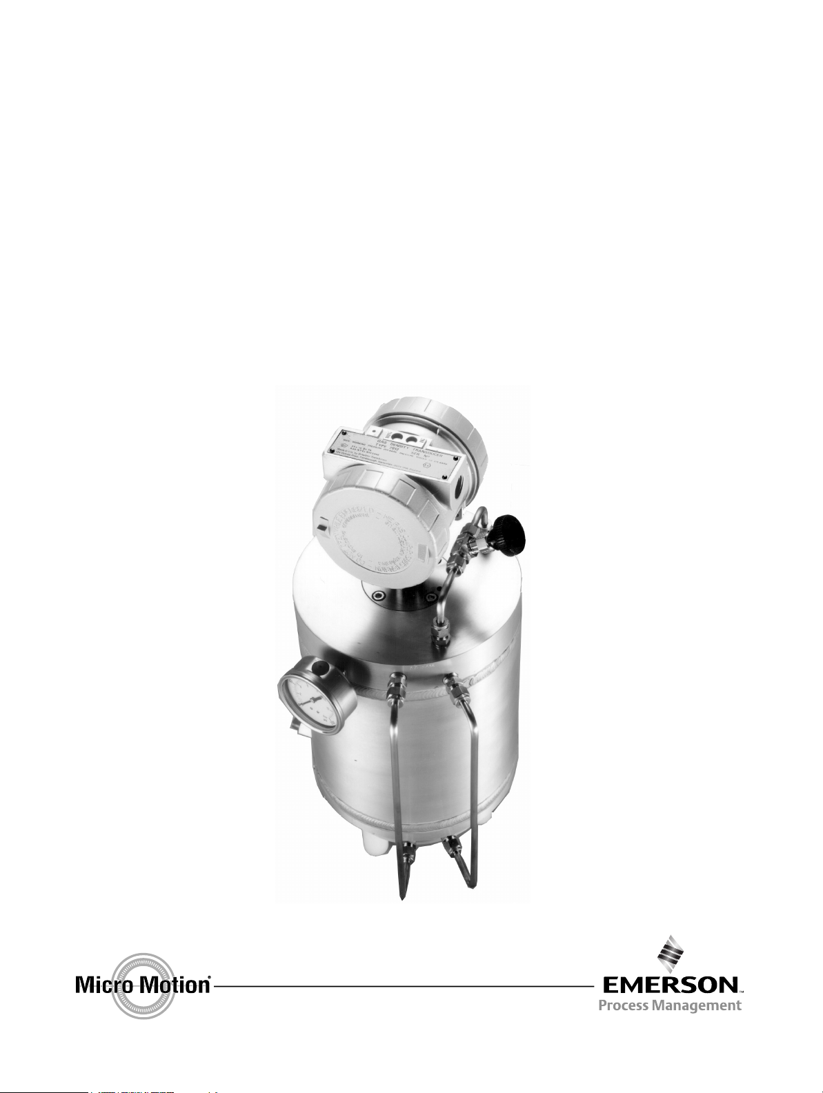
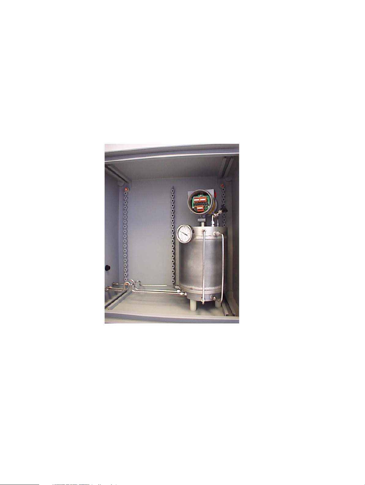
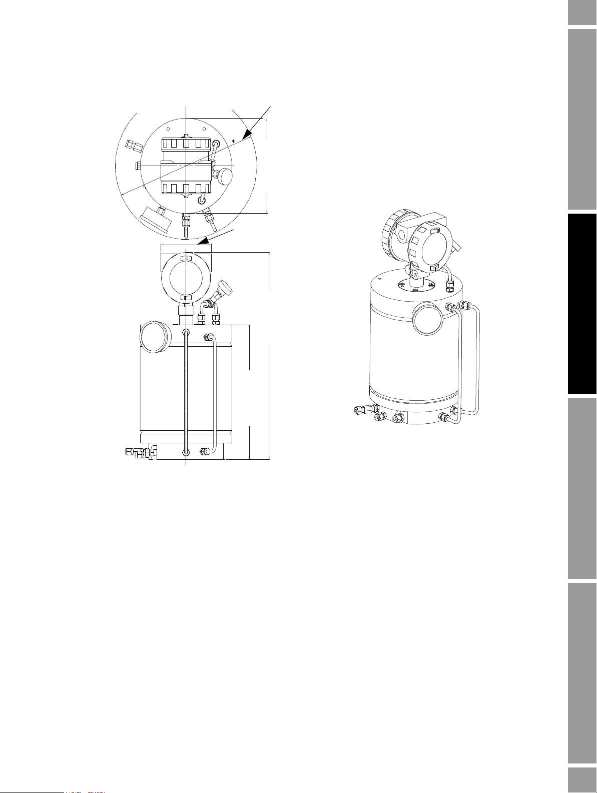
Figure 1-1 View of the 3098 specific gravity meter installed in a typical enclosure
2 Micro Motion 3098 Gas Specific Gravity Meter
Page 9
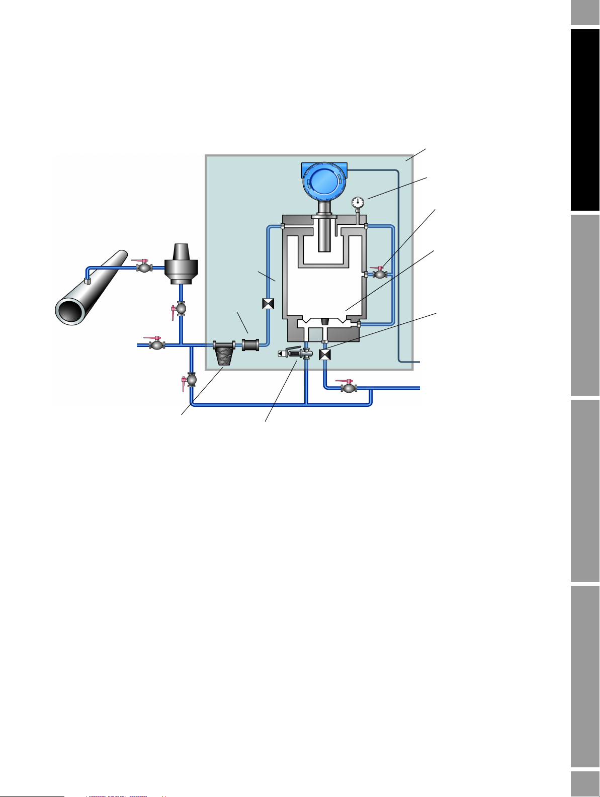
Introduction
Gas
line
3098
Pressure
regulator
Insulating cover
Control pressure indicator
Chamber filling valve E
Reference chamber
Output orifice
To signal converter
To v e n t
Outlet
Val ve C
Val ve B
Valve F (purging valve)
Vent and input for
calibration gases
Isolation
valve D
Val ve A
Input
orifice
Filter
Pressure relief valve
Diaphragm
Coalescing filter
1.3 Functional description
Figure 1-2 Schematic diagram of a typical 3098 specific gravity measuring system
Installation Procedure Accuracy ConsiderationsElectrical ConnectionsIntroduction
Installation and Configuration Manual 3
The 3098 specific gravity meter consists of a vibrating cylinder gas density meter surrounded by a gas
reference chamber, which helps to achieve good thermal equilibrium. The gas reference chamber has
a fixed volume that is initially pressurized with the actual line gas. It is then sealed by closing the
reference chamber filling valve, thus retaining a fixed measure and quantity of gas, now known as the
reference gas.
Note: Once the chamber has been filled, do not open the reference chamber filling valve again.
The sample gas enters the instrument at the enclosure side and passes through a filter, followed by a
pressure-reducing orifice. The sample gas is then fed through input pipework so that it enters the gas
density meter at the equilibrium temperature of the unit. The gas then flows down to a pressure
control valve chamber.
The pressure of the reference gas acts on the separator diaphragm and forces the line gas pressure to
rise until the pressures on both sides are equal, thus the gas pressures within the gas density meter and
the reference chamber are equal.
As the ambient temperature changes, the pressure of the fixed volume of reference gas will change as
defined by the Gas Laws. This change in pressure will affect the sample gas pressure within the gas
density meter such that the temperature and pressure changes are self-compensating.
Page 10

Introduction
If the sample gas pressure rises above that of the reference chamber pressure, the pressure control
valve opens to vent the excess gas via an outlet orifice in the enclosure side, so that the sample gas
pressure is reduced to equal the reference gas pressure. For gas to flow it is necessary that the supply
pressure is greater than the reference pressure, which in turn must be greater than the vent pressure.
(Typically the line pressure must be between 15% and 25% above that of the reference chamber
pressure).
Note: The principles of operation that describe this operation are given in Appendix B.
A pressure gauge is fitted in order to monitor the pressure within the gas density meter. This is
desirable when charging the reference chamber and also for general maintenance.
Electrical connections to the 3098 specific gravity meter are taken through the cable gland in the
enclosure side and then into the density meter’s electronics housing.
When the enclosure is sealed, the complete instrument is insulated so that rapid changes in ambient
temperature will not upset the temperature equilibrium of the unit and produce thermal shock errors.
Note: The 3098 specific gravity meter may have been supplied without an enclosure – see Safety
guidelines on page 1.
1.3.1 Meter sensing element
The gas density meter consists of a thin metal cylinder which is activated so that it vibrates in a hoop
mode at its natural frequency. The gas is passed over the inner and outer surfaces of the cylinder and
is thus in contact with the vibrating walls. The mass of gas which vibrates with the cylinder depends
upon the gas density and, since increasing the vibrating mass decreases the natural frequency of
vibration, the gas density for any particular frequency of vibration can be determined.
A solid state amplifier, magnetically coupled to the sensing element, maintains the conditions of
vibration and also provides the output signal.
1.3.2 Installation
The 3098 specific gravity meter has been designed to be installed mounted to a wall (wall mounted), a
typical installation set-up being given in Figure 1-3 below.
4 Micro Motion 3098 Gas Specific Gravity Meter
Page 11
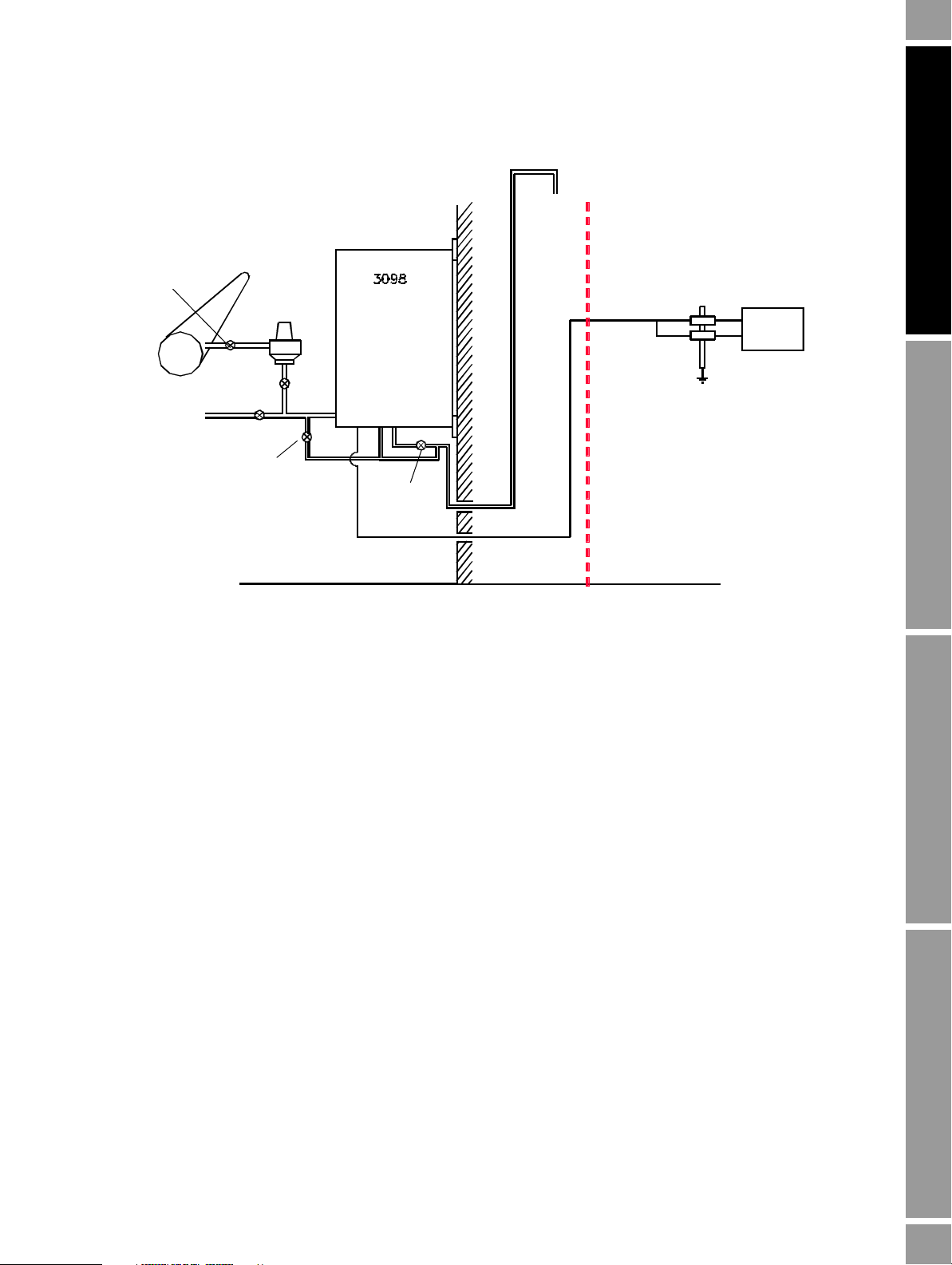
Introduction
SAFE AREA
HAZARDOUS AREA
Pressure
regulator
Isolation
valve
Val ve A
Val ve B
Gas for
calibration
Val ve F
Safety
barrier
Vent to
atmosphere
Signal
converter
Valve C
Electrical cable
In
Out
for example
where M
G
= molecular weight of gas (or gas mixture)
and M
A
= molecular weight of dry air
G
M
G
M
A
--------=
Figure 1-3 Typical 3098 specific gravity measuring system
Installation Procedure Accuracy ConsiderationsElectrical ConnectionsIntroduction
1.4 Definition of terms
1.4.1 Specific gravity
Specific gravity (G) is the ratio of the molecular weight of a gas (or gas mixture) to that of the
molecular weight of dry air; the molecular weight of dry air is normally assumed to be 28.96469 (see
Table 1-1).
Installation and Configuration Manual 5
Page 12

Introduction
for example
where p = absolute pressure (bars)
T = absolute temperature (degrees Kelvin)
M = molecular weight
Z = supercompressibility factor
R = gas constant (taken as 0.0831434)
ρ
s
pM
ZRT
------------=
for example
where ρ
G
= density of the gas or gas mixture
ρ
A
= density of air
Z
G
= supercompressibility factor of the gas or gas mixture
Z
A
= supercompressiblity factor of air
G
M
G
M
A
--------=
ρGZ
G
ρAZ
A
---------------=
ρ
r
Z
G
Z
A
-------
⋅=
ρr0.995899G 0.010096G
2
+=
1.4.2 Standard (base or normal) density
Standard (base or normal) density (
ρ
) is the absolute density of a gas at standard (base or normal)
s
conditions of temperature and pressure and is commonly used for standard volumne flow
determination from mass flow measurement.
1.4.3 Relative density
Relative density (
equal volume of dry air (see Table 1-1), where the weights of both gas
ρ
) is the ratio of the weight of a volume of gas (or gas mixture) to the weight of an
r
(or gas mixture) and air are
taken under identical conditions of temperature and pressure.
Note: Except for the effects of Boyle’s Law deviation upon both the gas (or gas mixture) and the air, G
and
ρ
r are synonymous.
The relative density of mixed hydrocarbon gases at 1 bar (14.50377 lb/in
(60°F) by empirical equation is:
6 Micro Motion 3098 Gas Specific Gravity Meter
2
) absolute and 15.56°C
Page 13

Introduction
1.5 Physical properties of gas compounds
Table 1-1 Physical properties of gas compounds
Compound Formula Molecular Weight
Hydrogen H
2
2.01594 0.069600
(1)
Specific Gravity
(2)
Helium He 4.00260 0.138189
Water Vapour H
Nitrogen N
O 18.01534 0.621976
2
2
28.01340 0.967157
Carbon Monoxide CO 28.01055 0.967058
Oxygen O
2
31.99880 1.104752
Argon Ar 39.94800 1.379197
(3)
Air
Hydrogen Sulphide H
Methane CH
Ethane C
Propane C
i-Butane C4H
n-Butane C4H
i-Pentane C
n-Pentane C5H
Hexane C6H
Heptane C
Octane C8H
– 28.96469 1.000000
S 34.07994 1.176603
2
4
2H6
3H8
10
10
5H12
12
14
7H16
18
16.04303 0.553882
30.07012 1.038165
44.09721 1.5522447
58.12430 2.006730
58.12430 2.006730
72.15139 2.491012
72.15139 2.491012
86.17848 2.975294
100.20557 3.459577
114.23266 3.943859
(1) Based upon 1961 atomic weights, referred to Carbon-12 Isotope (12 AMU), recommended by the International Commission of
Atomic Weights and the International Union of Pure and Applied Chemistry.
(2) Perfect gas specific gravity represents the ratio of molecular weight of compounds to the molecular weight of air.
(3) Molecular weight of air based upon components of atmospheric air given in Handbook of Chemistry & Physics, 53rd Edition
(1972–1973). Value of 28.96469 differs from figure 28.966 provided by NBS Circular 564 due to minute differences in component
content and changes in atomic weights of the elements given in 1961 (NBS value based upon 1959 atomic weights).
Installation Procedure Accuracy ConsiderationsElectrical ConnectionsIntroduction
1.6 Applications
The following are typical applications where specific gravity measurement is an essential parameter.
1.6.1 Supplementary gas supply
This system is used to top up normal supplies during peak periods. Specific gravity monitoring of a
propane/air mixture, for example, enables accurate control to be exercised over the ratio of the
mixture, therefore ensuring that the correct burning characteristic/calorific value is maintained.
Installation and Configuration Manual 7
Page 14

Introduction
Wobbe number
where CV = calorific value
G = specific gravity
CV
G
--------=
Base unit volume
for example
Mass flow
Base density
----------------------------------------=
Vs
M
ρ
s
-----=
M
G
P
AZA
Z
G
--------------
--------------------=
1.6.2 Wobbe index measurement
The burning characteristic of a gas must be well established for efficient combustion and to ensure
that no flame lift or flame light-back occurs on a particular burner. Three criteria are used to establish
this characteristic; calorific value, specific gravity and flame speed. The calorific value and specific
gravity are often combined to form the Wobbe Number:
1.6.3 Consumer gas costing
This major application has already been described in the introduction, mass to base volume unit
conversion, and may be further illustrated by the following equations:
8 Micro Motion 3098 Gas Specific Gravity Meter
Page 15

Chapter 2
Installation Procedure
2.1 Installation procedure
The procedure for installing the 3098 involves the following steps:
1. Check all components are present (Section 2.2).
2. Position and fix the 3098 enclosure (Section 2.3).
3. Connect the gas supply line (Section 2.3.2).
4. Fit the supplied coalescing filter into the gas supply line in accordance with manufacturer’s
instructions (Section 2.3.3) .
5. Make electrical connections (Section 2.4 and Chapter 3).
6. Select a reference pressure (Section 2.5).
7. Purge cycle and calibrate the 3098 (Section 2.6).
Installation Procedure Accuracy ConsiderationsElectrical ConnectionsIntroduction
2.2 Contents
The following items should be enclosed with the 3098 unit:
• 3098 specific gravity meter
• Labeled enclosure
• Enclosure mounting feet
• Enclosure mounting feet instructions
• 3098 Installation and Configuration manual (MMI-20014120)
• Safety instructions (CE-marked units only)
• Accessories kit
• Temperature Coefficient Calibration certificate
Note: Check that all the above items are present. If not, then contact your supplier immediately. (Be
aware that the 3098 may have been supplied without an enclosure.)
2.3 Installing the 3098 enclosure
The following installation instructions apply only to meters supplied with an enclosure (see Safety
guidelines on page 1). In all other cases, please refer to the system installer.
2.3.1 Important precautions
Take care to observe the precautions listed in Safety guidelines on page 1.
Installation and Configuration Manual 9
Page 16
Installation Procedure
The 3098 specific gravity meter is contained inside an IP-rated enclosure (which provides thermal
insulation) and a mounting system (consisting of a bracket and feet) to fix the unit in place. While this
structure is designed to minimize damage due to shocks, the box and unit must not be dropped.
Dropping the 3098 specific gravity meter either inside or outside its enclosure will damage the meter.
Contained inside the enclosure are four box feet which, when attached to a vertical wall will hold the
housing. A set of instructions on how to attach these feet is included inside the box. Enclosure
dimensions are in Section 2.7.
2.3.2 Connections
There are four connections that need to be made to the 3098 specific gravity meter: three gas pipeline
connections and one electrical connection through an IP-rated cable gland. The gas pipeline
connections take the form of ¼" Swagelok bulkhead fittings, and are used for the gas input, gas output
and pressure relief lines.
Each connection is labelled.
Connecting the gas input line to the wrong bulkhead fitting might result in damage.
A gas density meter is used as the measuring instrument in the 3098 specific gravity meter and needs
to be connected inside the enclosure. All wiring should be connected through the cable gland to
maintain the enclosure’s overall protection to dust and water ingress.
At all stages during calibration and operation, the 3098 specific gravity meter is designed to function
with the enclosure sealed. This allows the unit to operate in the condition of thermal equilibrium,
which is essential for accurate measurement.
2.3.3 Coalescing filter
Ensure that the coalescing filter (as supplied) is fitted into the gas supply line to the 3098 meter. This
MUST be done in order to comply with the ATEX/IECEx approval requirements.
2.4 Electrical connections and safety barriers / galvanic isolators
When the 3098 specific gravity meter is mounted in a hazardous area, the electrical connections to the
meter must conform to stringent conditions. For electrical connections between the meter and its
associated flow computer/signal converter, for ATEX/IECEx installations see the ATEX/IECEx Safety
Instructions booklet (available at www.micromotion.com) and for CSA installations see Appendix D.
Electrical cable connection to the 3098 specific gravity meter is made to the terminal block inside the
resonator electronics housing (for example, inside the enclosure). Poor connection to the terminals
will prevent correct operation but will not damage the unit – provided that safety barriers or galvanic
isolators are included in the circuit for hazardous areas or the maximum power supply does not
exceed the 33 V maximum limit (as described in Chapter 3).
The power supplied to the meter terminals should be in the range of 15.5 to 33 Vdc with the average
current drawn by the unit being < 20 mA. If the current consumption exceeds this value, the polarity
of the connections should be checked.
A full description of how to connect the 3098 specific gravity meter to a signal converter/flow
computer is given in Chapter 3.
10 Micro Motion 3098 Gas Specific Gravity Meter
Page 17
Installation Procedure
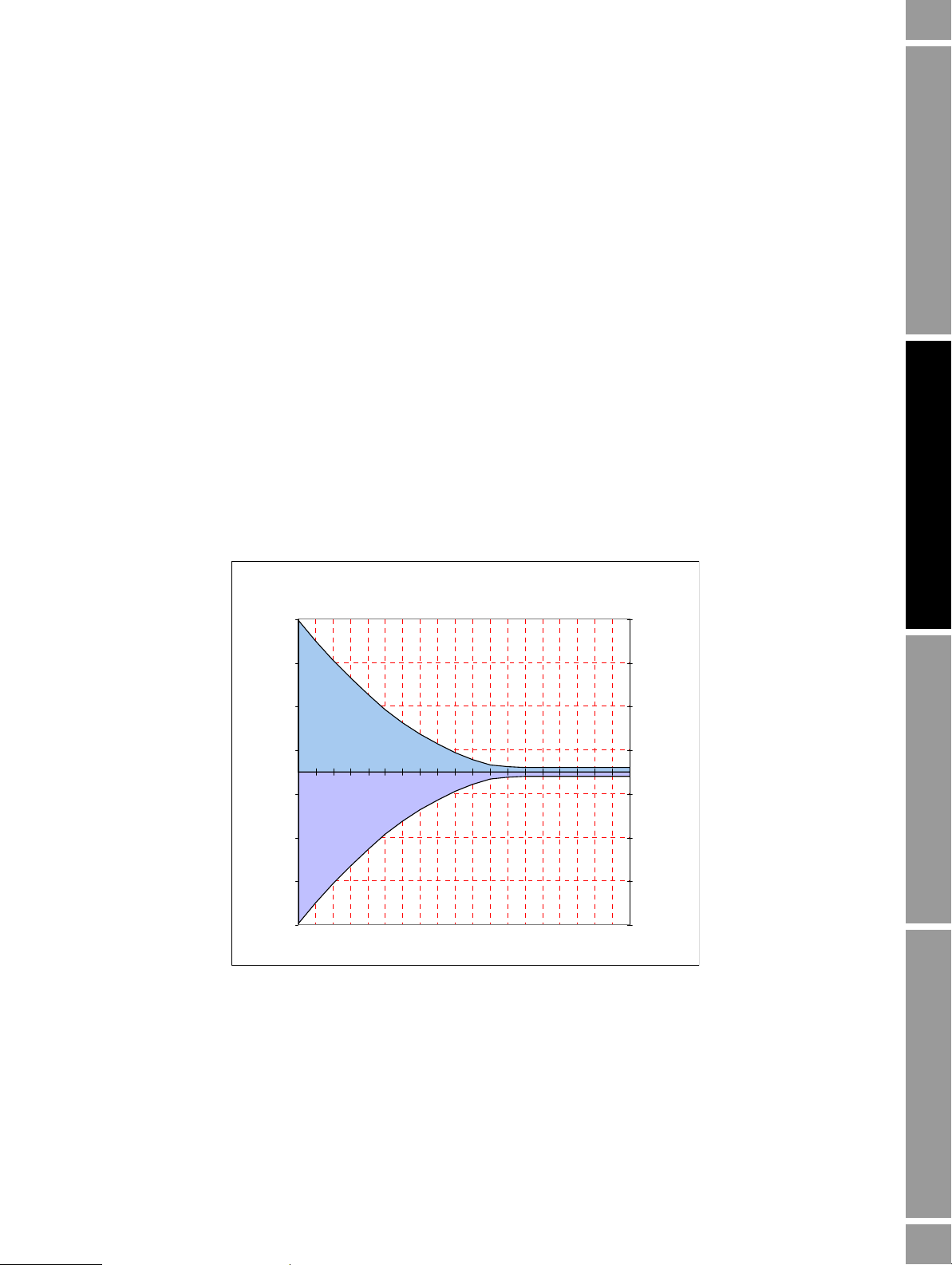
Typical Total Error/°C vs Reference Chamber Pressure
For NATURAL GAS APPLICATIONS ONLY.
-0.035
-0.025
-0.015
-0.005
0.005
0.015
0.025
0.035
0.5 1 1.5 2 2.5 3 3.5 4 4.5 5 5.5 6 6.5 7 7.5 8 8.5 9 9.5 10
Reference Chamber Pressure (Bar A)
Typ % of FS Specific Gravity /°C
-0.035
-0.025
-0.015
-0.005
0.005
0.015
0.025
0.035
Typ % of FS Specific Gravity /°C
2.5 Reference chamber pressure determination
Once the 3098 specific gravity meter has been placed in its fixture and all relevant pipework and
electrical connections made, the reference chamber pressure needs to be determined.
The gas type and reference chamber pressure define the ‘controlled condition’ at which the unit
allows gas to flow and establishes a direct relationship between density and the specific gravity of the
sample gas.
The choice of reference chamber gas pressure is dependent upon three factors:
• The span of specific gravity to be measured
• The expected change in sample gas supercompressibility, Z
• The accuracy required
The graph below gives an indication of the typical errors associated with using different reference
chamber pressures for natural gas with a reasonably constant specific gravity (in the range of
0.55 – 0.8). This is typical for natural gas metering market, where the gas is available at a line
pressure of 7 Bar abs.
As can be seen, below 7 Bar abs, the total error begins to increase; using a higher reference pressure
will not improve accuracy, but may encourage gas leakage. Therefore, for the conditions specified,
7 Bar is the recommended pressure.
Installation Procedure Accuracy ConsiderationsElectrical ConnectionsIntroduction
Figure 2-1 Typical total error/°C versus reference chamber pressure
This graph should only be used for natural gas applications, and.gives typical errors seen on the 3098
specific gravity meter if it is not used at the recommended reference chamber pressure.
If the span of specific gravity or change in supercompressibility, Z, is large, and the gas is not a
methane/nitrogen mix, then the best reference chamber pressure can still be determined. The
calculation for doing this is explained in Chapter 4.
Once the desired reference pressure has been found, the 3098 specific gravity meter can now be purge
cycled and then calibrated.
Installation and Configuration Manual 11
Page 18
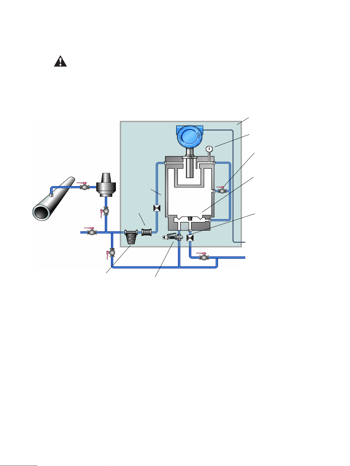
Installation Procedure
Gas
line
3098
Pressure
regulator
Insulating cover
Control pressure indicator
Chamber filling valve E
Reference chamber
Output orifice
To signal converter
To v e n t
Outlet
Val ve C
Val ve B
Valve F (purging valve)
Vent and input for
calibration gases
Isolation
valve D
Val ve A
Input
orifice
Filter
Pressure relief valve
Diaphragm
Coalescing filter
2.6 Set-up procedure – purge cycling and calibration
The pressure relief valve has been factory set for the unit to conform to the Pressure Equipment
Directive. Under no circumstances should this setting be changed. For further information,
contact the factory using the details on the back page.
Figure 2-2 Schematic diagram of a typical 3098 specific gravity measuring system
12 Micro Motion 3098 Gas Specific Gravity Meter
The procedure for purging and calibrating the 3098 specific gravity meter is given below (see
Figure 2-2 for reference):
1. Ensure isolation valve D is closed.
2. Ensure valve A is closed.
3. Ensure valve B is closed.
4. Ensure valve F is closed.
5. Open valve C.
6. Open chamber filling valve E.
7. Set the pressure regulator to the required value – for example, the actual working pressure of
the system.
8. Open isolation valve D.
9. Open valve A and allow gas to flow for 3 minutes.
Page 19

Installation Procedure
⎥
⎦
⎤
⎢
⎣
⎡
pressure regulatormax
7 x 3
= cycles purge of Number
() ()
()
(2)
(1)
2
1210
2
2
2
1
21
2
τ
ττ
KSGK
SGSG
K
−=
⎥
⎦
⎤
⎢
⎣
⎡
−
−
=
Purge cycling
10. Close valve C.
11. When Control Pressure Indicator is at the desired value, shut valve A and open valve F. Allow
the gas to vent to atmospheric pressure.
12. Close valve F and open valve A.
13. When Control Pressure Indicator is at the desired value, shut valve A and open valve F. Allow
the gas to vent to atmospheric pressure.
Steps 12 and 13 define the purging cycle required for setting up the reference chamber gas in
the 3098 specific gravity meter. The number of times that this procedure should be repeated
depends upon the gas regulator pressure used and is defined by:
14. Once the required number of cycles has been performed, close valve F and open valve A.
15. When the desired gas pressure inside the chamber has been reached (as shown by the Control
Pressure Indicator) shut the chamber valve.
DO NOT open the chamber valve again. The gas now inside the 3098 chamber is the line reference
gas.
3098 specific gravity meter calibration using two known gases
16. Close valve A.
17. Connect the first calibration gas bottle to the pipework and set the pressure to be typically 25%
above that inside the reference chamber.
18. Open valve B.
19. Ensure valve C is open and allow gas to flow until the time period as measured by the signal
converter/flow computer is stable to ±1 ns or better (the typical stability will be better than
this). [For the required electrical connections see Chapter 3]
20. Note this time period (τ
) together with the certified SG from the bottle of gas (SG1).
1
21. Shut valve B.
22. Replace the first calibration gas bottle with the second calibration gas bottle.
23. Set pressure to typically 25% above that inside the reference chamber and open valve B.
24. Allow gas to flow until the time period shown by the meter is stable to ±1 ns or better.
25. Note this time period (τ
) and the certified SG from the bottle of gas (SG2).
2
26. Apply these noted numbers into equations (1) and (2) below:
Installation Procedure Accuracy ConsiderationsElectrical ConnectionsIntroduction
You can enter this information directly into the Calibration Certificate example in Section 4.4.
For an online version of this certificate, download the Calibration Certificate Excel file at
www.micromotion.com (located on the 3098 products page) or access the calcert.xls file on
Installation and Configuration Manual 13
the floppy disk shipped with the product.
Page 20

Installation Procedure
27. Shut valve B and disconnect the second calibration gas bottle from pipework.
28. Open the isolation valve D.
29. Open valve A.
If the application is running with a reference pressure less than 45.5 psi (3 Bar A), the maximum
flow rate that can be used for correct operation is 50 cc/s. A full explanation of this effect is given
in Chapter 4.
The unit should now give a live reading of the measured gas SG. If the unit does not output a
sensible reading, certain checks can be made. These checks are summarized in Chapter 5.
If optimum SG accuracy is required, the optimization method described in Appendix A – which
compensates for errors due to gas velocity of sound, compressibility and temperature coefficient
– should be used.
For optimum accuracy, the time period (τ) must be resolved to ±0.1 ns. This can be achieved
using 7950/7951 signal converters and flow computers set to a cycle time of 10 s.
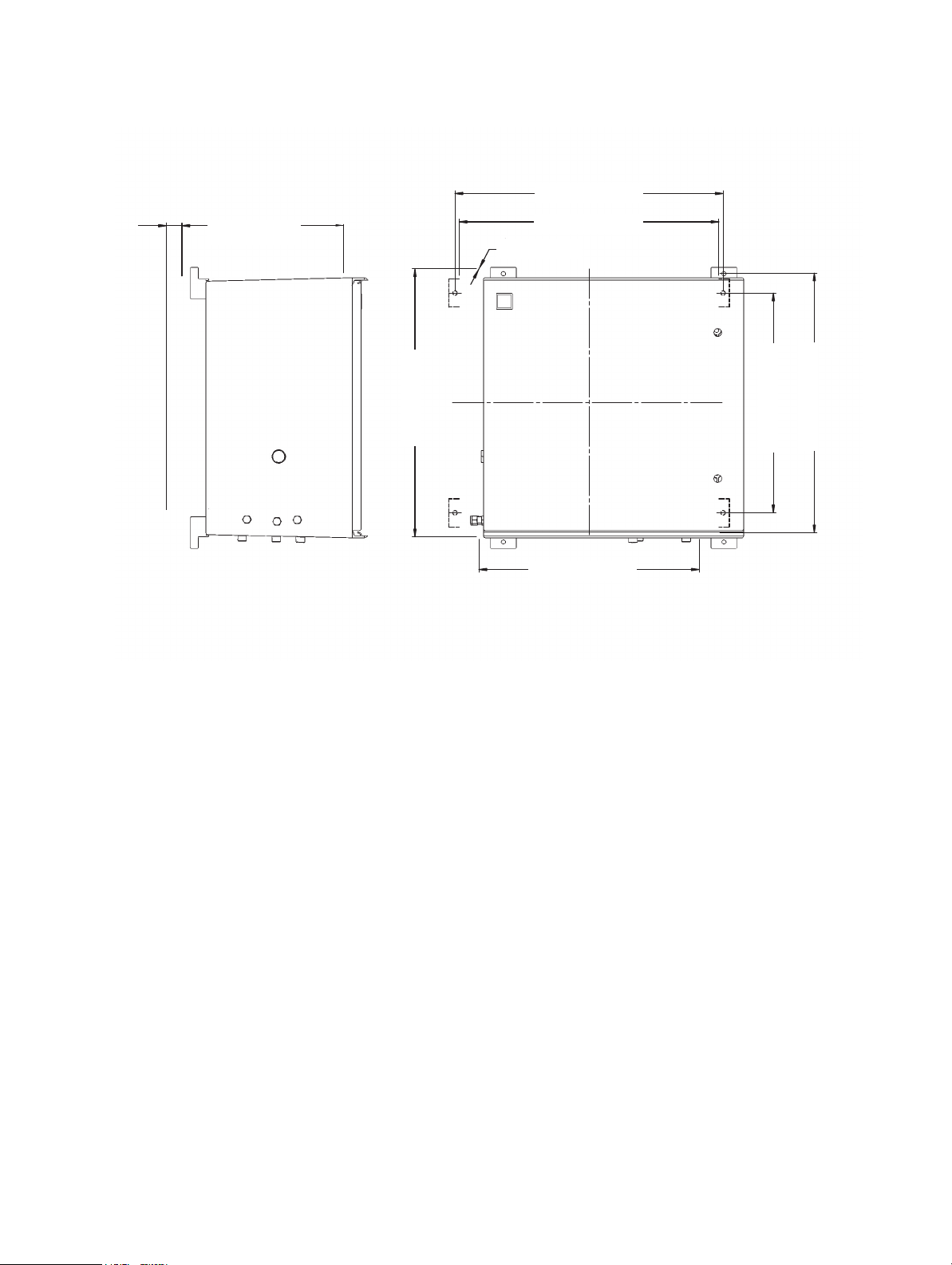
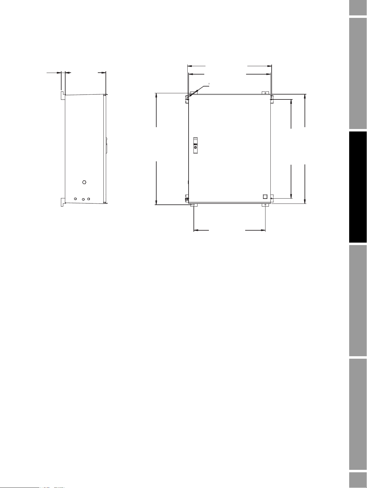
2.7 Outline dimensional drawings
Figure 2-3 shows a 3098 specific gravity meter without an enclosure. For dimensions of small and
large enclosures, see Figure 2-4 and Figure 2-5.
14 Micro Motion 3098 Gas Specific Gravity Meter
Page 21
Installation Procedure
Dimensions in inches (mm)
∅12.4 (314)
∅8 (203.2)
4.4 (112)
17.4 (442)
11.3 (286.4)
Figure 2-3 3098 specific gravity meter without an enclosure
Installation Procedure Accuracy ConsiderationsElectrical ConnectionsIntroduction
Installation and Configuration Manual 15
Page 22
Installation Procedure
20.3 (516)
19.7 (500)
12 (300)
1.2
(30)
1
/3 (8.5)
20.3 (516)
17.1 (423)
17.1 (423)
19.7 (500)
Dimensions in inches (mm)
Figure 2-4 3098 specific gravity meter with a small enclosure
16 Micro Motion 3098 Gas Specific Gravity Meter
Page 23
Installation Procedure
24.3 (616)
23.6 (600)
12 (300)
1.2
(30)
1
/3 (8.5)
32.1 (816)
20.6 (523)
28.5 (723)
31.5 (800)
Dimensions in inches (mm)
Figure 2-5 3098 specific gravity meter with a large enclosure
Installation Procedure Accuracy ConsiderationsElectrical ConnectionsIntroduction
Installation and Configuration Manual 17
Page 24

Installation Procedure
18 Micro Motion 3098 Gas Specific Gravity Meter
Page 25

Chapter 3
123
4567
8
9110 11 12
SIG A
SIG B
PRT
Electrical Connections
This chapter contains details and wiring diagrams for connecting the 3098 specific gravity meter to
7950/51 signal converters and flow computers, and more generally to other equipment in both
hazardous and non-hazardous situations.
3.1 Introduction
The electrical connections to the 3098 specific gravity meter are made to the gas density meter held
inside the enclosure. When installed in hazardous areas, connections between the meter and the power
supply/readout equipment must be completed through zener safety barriers [or galvanic isolators].
The electrical cable enters the enclosure (if supplied, see Safety guidelines on page 1) through a cable
gland assembly and then passes into the amplifier housing.
The meter terminal layout is shown in Figure 3-1.
The amplifier housing has two chambers. The one nearest the cable gland axis contains the terminals
for connection to the meter/signal processing instrument. The other chamber contains the maintaining
amplifier unit. The amplifier board is encapsulated in a circular plastic container, with the complete
module secured by a keyway and a centrally positioned clamping screw. Behind the amplifier there is
an interconnect terminal board which links the sensor to the maintaining amplifier, and the amplifier
to the user connect board (see Figure 3-2).
Figure 3-1 Main terminal board connections
Installation Procedure Accuracy ConsiderationsElectrical ConnectionsIntroduction
Installation and Configuration Manual 19
Page 26

Electrical Connections
INTERCONNECT PCB
78121503
TERMINAL PCB
78121502
SPOOLBODY
78121201
AM PL IFIE R P CB
78121501
PICK UP
COIL
DRIVE
COIL
BN PL1
13 20
2
BN
BN
I/P +
R PL 2
14 19
3
O
R
I/P -
O PL 5
16 18
4
R
O
O/P +
Y PL 6
15 17
5
B
Y
O/P -
R PL 3
22
V +
G PL 4
21
V -
23
12 4 3
- B+ -
SIG BSIG A
O PL 7
FREQ. OUT
Figure 3-2 Interconnection diagram
3.2 EMC cabling and earthing
To meet the EC Directive for EMC (Electromagnetic Compatibility), it is recommended that the meter
be connected using a suitable instrumentation cable and earthed through the meter body and
pipework.
The instrumentation cable should have an individual screen, foil, or braid over each twisted pair and
an overall screen to cover all cores. Where permissible, the overall screen should be connected to
earth at both ends (360° bonded at both ends). The inner individual screen should be connected at
only one end, the controller end (for example, signal converter end).
Note: For intrinsic safety, termination of the inner individual screen(s) to earth in the hazardous area
is not generally permitted.
Note: Use suitable cables that meet BS5308 multi-pair instrumentation Types 1 or 2.
3.3 Certificate conditions for hazardous areas
For details of hazardous area installations, see the ATEX/IECEx Safety Instructions booklet (available
at www.micromotion.com) for ATEX/IECEx installations and see Appendix D for CSA installations.
The 3098 specific gravity meter can be electrically connected in either a 2-wire or 3-wire
configuration. A schematic block diagram of these two types is given in Figure 3-3 and Figure 3-4.
20 Micro Motion 3098 Gas Specific Gravity Meter
Page 27

Electrical Connections
A
D
B
C
CYLINDER
ACTIVATING
COIL
PICK OFF
COIL
PART OF
SPOOLBODY
VIBRATING
CYLINDER
PICK OFF CURRENT
CYLINDER DRIVE CURRENT
USER CONNECT BOARD
NEGATIVE
SUPPLY
VOLTAGE (0V)
SIGNAL
OUTPUT
330R
POSITIVE
SUPPLY
VOLTAGE (+V)
SENSING ELEMENT AMPLIFIER UNIT
A
D
B
C
CYLINDER
ACTIVATING
COIL
PICK OFF
COIL
PART OF
SPOOLBODY
VIBRATING
CYLINDER
PICK OFF CURRENT
CYLINDER DRIVE CURRENT
USER CONNECT BOARD
NEGATIVE
SUPPLY
VOLTAGE (0V)
SIGNAL
OUTPUT
POSITIVE
SUPPLY
VOLTAGE (+V)
SENSING ELEMENT AMPLIFIER UNIT
Figure 3-3 Schematic block diagram of meter circuit (2-wire system)
Installation Procedure Accuracy ConsiderationsElectrical ConnectionsIntroduction
Figure 3-4 Schematic block diagram of meter circuit (3-wire system)
3.4 Use with signal converters and flow computers
The meter can be operated in two general environments, either in safe areas or in hazardous areas.
When used in hazardous areas, safety barriers or galvanic isolators must be placed between the meter
and the signal converter/flow computer.
Installation and Configuration Manual 21
Page 28

Electrical Connections
3098 meter
1
+
SIG A
2
-
3
+
SIG B
4
-
330R
7950 Flow Com puter/Signal Converter
Density power +PL10/1
Ch.3
PL10/2
PL10/3
PL10/4
PL10/5
Ch.4
PL10/6
PL10/7
PL10/8
Density input +
Density input -
Density power -
3098 meter
1
+
SIG A
2
-
3
+
SIG B
4
-
MTL 787 (+ve)
3
4
1
2
Hazardous A rea
Safe Area
7950 Flow Computer/Signal Converter
Density power +PL10/1
Ch.3
PL10/2
PL10/3
PL10/4
PL10/5
Ch.4
PL10/6
PL10/7
PL10/8
Density input +
Density input -
Density power -
When operating in a safe area with a 3-wire system, the line resistance between meter and signal
converter must be greater than 40 ohms. This can be achieved by placing a suitable resistor in the line
or by using the inherent resistance of the cable used (if the resistance per km and length of cable used
is sufficient).
Given these conditions, we recommend that the maximum cable length between the 3098 specific
gravity meter and signal converter – assuming a BS5308 standard cable – is 2 km.
When the 3098 specific gravity meter is installed in a hazardous area, see the ATEX/IECEx Safety
Instructions booklet (available at www.micromotion.com) for ATEX/IECEx installations and see
Appendix D for CSA installations.
For the purposes of clarity, all wiring diagrams describing a safe area setup using the 3-wire system
have had a 40-ohm resistor placed into the +24 V power supply line.
3.5 System connections (7950/7951)
The density and power connections to the 3098 specific gravity meter in safe and hazardous areas are
shown in the following diagrams:
3.5.1 7950 2-wire configuration
Figure 3-5 7950 signal converter and gas specific gravity 2-wire system (safe area)
Figure 3-6 7950 signal converter and gas specific gravity 2-wire system with shunt-diode safety barrier
(hazardous area)
22 Micro Motion 3098 Gas Specific Gravity Meter
Page 29

Electrical Connections
3098 meter
1
+
SIG A
2
-
3
+
SIG B
4
-
MTL 5532
4
5
14
13
Hazardous Area Safe Area
Density power +PL10/1
Ch.3
PL10/4
PL10/3
PL10/2
PL10/5
Ch.4
PL10/8
PL10/7
PL10/6 Density input +
Density input -
Density power -
7950 Flow Computer/Signal Converter
10k
1
12
11
2kR
ZD1
Barrier trip level switch settings Zener voltage
12V 6.2V
6V 13V
3V 16V
3098 meter
1
+
SIG A
2
-
3
+
SIG B
4
-
7950 Flow Computer/Signal Converter
Density power +PL10/1
Ch.3
PL10/2
PL10/3
PL10/4
PL10/5
Ch.4
PL10/6
PL10/7
PL10/8
Density input +
Density input -
Density power -
Figure 3-7 7950 signal converter and gas specific gravity 2-wire system with galvanic isolator (hazardous
area)
Installation Procedure Accuracy ConsiderationsElectrical ConnectionsIntroduction
Note: When the ATEX/IECEx-approved specific gravity meter is installed in a hazardous area, the
safety instruction booklet shipped with the unit is the authoritative document.
3.5.2 7950 3-wire configuration
Figure 3-8 7950 signal converter and gas specific gravity 3-wire system (safe area)
Installation and Configuration Manual 23
Page 30

Electrical Connections
3098 meter
1
+
SIG A
2
-
3
+
SIG B
4
-
Hazardous Area Safe Area
MTL 787 (+ve)
3
4
1
2
7950 Flow Computer/Signal Converter
Density power +PL10/1
Ch.3
PL10/2
PL10/3
PL10/4
PL10/5
Ch.4
PL10/6
PL10/7
PL10/8
De ns ity in put +
De ns ity in put -
Density power -
Meter
1
+
SIG A
2
-
3
+
SIG B
4
-
MTL 5532
4
1
14
13
Hazardous Area Safe Area
Density power +PL10/1
Ch.3
PL10/4
PL10/3
PL10/2
PL10/5
Ch.4
PL10/8
PL10/7
PL10/6 Density input +
Density input -
Density power -
7950 Flow Computer/Signal Converter
5 12
11
2kR
3098 meter
1
+
SIG A
2
-
3
+
SIG B
4
-
330R
7951 Signal Converter/Flow Com puter
24V pwr +
PL5/9 (SK6/22)
Ch.3
PL5/5 (SK6/18)
PL5/6 (SK6/19)
PL5/10 (SK6/24)
PL5/9 (SK6/22)
Ch.4
PL5/7 (SK6/20)
PL5/8 (SK6/21)
PL5/10 (SK6/24)
Den ip +
De n ip -
24V pwr -
(0V dc)
(Den -)
(+24 V d c)
(Den +)
Figure 3-9 7950 signal converter and gas specific gravity 3-wire system with shunt-diode safety barrier
(hazardous area)
Figure 3-10 7950 signal converter and gas specific gravity 3-wire system with galvanic isolator (hazardous
area)
Note: The barrier trip level switch should be set to 3 volts.
Note: When the ATEX/IECEx-approved specific gravity meter is installed in a hazardous area, the
safety instruction booklet shipped with the unit is the authoritative document.
3.5.3 7951 2-wire configuration
Figure 3-11 7951 flow computer/7951 signal converter gas specific gravity 2-wire system (safe area)
24 Micro Motion 3098 Gas Specific Gravity Meter
Page 31

Electrical Connections
3098 meter
1
+
SIG A
2
-
3
+
SIG B
4
-
MTL 787 (+ve)
3
4
1
2
Hazardous Area
Safe Area
7951 Signal Converter/Flow Computer
24V pwr +
PL5/9 (SK6/22)
Ch.3
PL5/5 (SK6/18)
PL5/6 (SK6/19)
PL5/10 (SK6/24)
PL5/9 (SK6/22)
Ch.4
PL5/7 (SK6/20)
PL5/8 (SK6/21)
PL5/10 (SK6/24)
Den ip +
Den ip -
24V pwr -
(0V dc)
(Den -)
(+24V dc)
(Den +)
3098 meter
1
+
SIG A
2
-
3
+
SIG B
4
-
MTL 5532
4
5
14
13
Hazardous Area Safe Area
Ch.3 Ch.4
7951 Flow Computer/Signal Converter
10k
1
12
11
2kR
ZD1
24V pwr +
PL5/9 (SK6/22)
PL5/5 (SK6/18)
PL5/6 (SK6/19)
PL5/10 (SK6/24)
PL5/9 (SK6/22)
PL5/7 (SK6/20)
PL5/8 (SK6/21)
PL5/10 (SK6/24)
Den ip +
Den ip -
24V pwr (0V dc)
(Den -)
(+24V dc)
(Den +)
Barrier trip level switch settings Zener voltage
12V 6.2V
6V 13V
3V 16V
Figure 3-12 7951 flow computer/7951 signal converter gas specific gravity 2-wire system with shunt-diode
safety barrier (hazardous area)
Figure 3-13 7951 flow computer/7951 signal converter gas specific gravity 2-wire system with galvanic
isolator (hazardous area)
Installation Procedure Accuracy ConsiderationsElectrical ConnectionsIntroduction
Note: When the ATEX/IECEx-approved specific gravity meter is installed in a hazardous area, the
safety instruction booklet shipped with the unit is the authoritative document.
Installation and Configuration Manual 25
Page 32

Electrical Connections
3098 meter
1
+
SIG A
2
-
3
+
SIG B
4
-
7951 Signal Converter/Flow Computer
24V pwr +
PL5/9 (SK6/22)
Ch.3
PL5/5 (SK6/18)
PL5/6 (SK6/19)
PL5/10 (SK6/24)
PL5/9 (SK6/22)
Ch.4
PL5/7 (SK6/20)
PL5/8 (SK6/21)
PL5/10 (SK6/24)
Den ip +
Den ip -
24V pwr -
(0V dc)
(Den -)
(+24V dc)
(Den +)
3098 meter
1
+
SIG A
2
-
3
+
SIG B
4
-
Hazardous Area
Safe Area
MTL 787 (+ve)
3
4
1
2
7951 Signal Converter/Flow Computer
24V pwr +
PL5/9 (SK6/22)
Ch.3
PL5/5 (SK6/18)
PL5/6 (SK6/19)
PL5/10 (SK6/24)
PL5/9 (SK6/22)
Ch.4
PL5/7 (SK6/20)
PL5/8 (SK6/21)
PL5/10 (SK6/24)
Den ip +
Den ip -
24V pwr -
(0V d c)
(De n -)
(+24V dc)
(Den +)
Meter
1
+
SIG A
2
-
3
+
SIG B
4
-
MTL 5532
4
1
14
13
Hazardous Area Safe Area
7951 Flow Computer/Signal Converter
5 12
11
2kR
24V pwr +
PL5/9 (SK6/22)
Ch.3
PL5/5 (SK6/18)
PL5/6 (SK6/19)
PL5/10 (SK6/24)
PL5/9 (SK6/22)
Ch.4
PL5/7 (SK6/20)
PL5/8 (SK6/21)
PL5/10 (SK6/24)
Den ip +
Den ip -
24V pwr (0V dc)
(Den -)
(+24V dc)
(Den +)
3.5.4 7951 3-wire configuration
Figure 3-14 7951 flow computer/7951 signal converter gas specific gravity 3-wire system (safe area)
Figure 3-15 7951 flow computer/7951 signal converter gas specific gravity 3-wire system with shunt-diode
safety barrier (hazardous area)
Figure 3-16 7951 flow computer/7951 signal converter gas specific gravity 3-wire system with galvanic
isolator (hazardous area)
26 Micro Motion 3098 Gas Specific Gravity Meter
Note: The barrier trip level switch should be set to 3 volts.
Note: When the ATEX/IECEx-approved specific gravity meter is installed in a hazardous area, the
safety instruction booklet shipped with the unit is the authoritative document.
Page 33

Electrical Connections
3098 meter
1
+
SIG A
2
-
3
+
SIG B
4
-
330R
1nF
1nF
Power +
Power -
Signal +
Signal -
2.3V pk to pk
3098 meter
1
+
SIG A
2
-
3
+
SIG B
4
-
MTL 787 (+ve)
3
4
1
2
Hazardous Area Safe Area
Power + (24.25 to 27V DC, 30mA)
Power -
Signal +
Signal -
1nF
1nF
10kΩ
3.6 System connections (customer’s own equipment)
3.6.1 Non-hazardous areas
Power supply to Density Meter: 15.5 to 33 Vdc, < 20 mA.
Power supply to PRT: 5 mA maximum
The frequency at which the meter is operating can be detected in one of two ways:
• For the 2-wire option, a 330 Ω series resistor should be used in the +ve power line. The
electrical connections to be made are shown in Section 3.6.3. The signal across the 330 Ω
resistor is greater than 2 V peak-to-peak. The minimum impedance of the signal measuring
equipment should be 500 kΩ. Where necessary, the 1 nF capacitors will block the power
supply DC voltage to the measuring equipment.
• For the 3-wire option, the frequency can be measured directly. The electrical connections to be
made are shown in Section 3.6.4.
3.6.2 Hazardous areas
For details of hazardous area installations, see the ATEX/IECEx Safety Instructions booklet (available
at www.micromotion.com) for ATEX/IECEx installations and see Appendix D for CSA installations.
Installation Procedure Accuracy ConsiderationsElectrical ConnectionsIntroduction
3.6.3 Customer's equipment, 2-wire configuration
Figure 3-17 Electrical connections for meter 2-wire option used with customers’ own equipment (safe area)
Figure 3-18 Electrical connections for meter 2-wire option used with customers’ own equipment and
shunt-diode safety barrier (hazardous area)
Installation and Configuration Manual 27
Page 34

Electrical Connections
3098 meter
1
+
SIG A
2
-
3
+
SIG B
4
-
Power +
Power -
Signal +
Signal -
6V pk to pk
3098 meter
1
+
SIG A
2
-
3
+
SIG B
4
-
MTL 787 (+ve)
3
4
1
2
Hazardous Area Safe Area
Power + (24.25 to 27V DC, 30mA)
Power -
Signal +
Signal -
1nF
3.6.4 Customer's equipment, 3-wire configuration
Figure 3-19 Electrical connections for meter 3-wire option used with customer’s own equipment (safe area)
Figure 3-20 Electrical connections for meter 3-wire option used with customers’ own equipment and
shunt-diode safety barrier (hazardous area)
3.7 Post-installation checks
After installation, the following procedure will indicate to a high degree of confidence that the meter
is operating correctly.
1. Electrical Check
Measure the current consumption and the supply voltage at the meter amplifier. This should be
within the following limits:
• 15.5 Vdc to 33 Vdc (Safe Areas)
• 15.5 Vdc to 24 Vdc (Hazardous Areas)
• 10 mA at 24 V dc input (Nominal input current)
• 17 mA maximum (Safe and Hazardous Areas, any input voltage)
2. Stability Check
Check the stability of the frequency output signal using a period meter on a 1000-cycle count.
The measurement scatter should be within ±2 ns. If this value is exceeded, it is likely that dirt
is present on the sensing element. This test may be performed at any gas density, provided that
the latter is not changing.
28 Micro Motion 3098 Gas Specific Gravity Meter
Page 35

Chapter 4
Accuracy Considerations
This chapter provides a method for estimating the accuracy of 3098 specific gravity meter
measurements under various conditions.
4.1 Accuracy considerations
The ‘controlled condition’ which establishes a direct relationship between density and the specific
gravity of the sample gas is mainly determined by the pressure and the type of gas used in the
reference chamber. The choice of reference chamber gas pressure is dependent upon:
• The span of specific gravity to be measured
• The expected change in sample gas supercompressibility, Z
• The accuracy required
The exact choice in reference gas pressure is made after considering all the error sources for that
application. To simplify the selection, Table 4-1 is provided which can be reproduced by the user. In
general, unless a pump is used to boost the pipeline pressure, the reference gas pressure at 20 °C must
be at least 10% less than the minimum line pressure, to ensure gas flow over the operating
temperature range.
4.1.1 Example 1
When a gas has a relatively low and reasonably constant specific gravity, and is available at a line
pressure greater than 7 Barg (100 psig) such as natural gas measurement in the range 0.55–0.8, a very
high accuracy is possible using a reference pressure of 7 Barg. (See Table 4-2 for a worked example).
4.1.2 Example 2
Installation Procedure Accuracy ConsiderationsElectrical ConnectionsIntroduction
If large range specific gravity measurements are to be made, or where changes in the
supercompressibility factor of the sample gases become significant, (such as in flare gases or air/CO
mixes), a much lower reference gas pressure is required. (See Table 4-3 for N
Installation and Configuration Manual 29
/CO2 mix).
2
2
Page 36

Accuracy Considerations
4.1.3 Calculating parameters
Table 4-1 3098 specific gravity meter control pressure selection (natural gas)
3098 Specific Gravity Meter Control Pressure Selection
Date: Type of gas: Specific gravity
2
Control pressure
at 20°C
Density range at 20°C
abs.)
(lb/in
(bar abs.)
3
) 0.79–1.5 1.32–3.0 2.66–3.8 4.58–6.72
(kg/m
range:
18
1.2
Measurement errors (% of FS specific gravity/°C) due to:
Density meter temperature coefficient
Gas compressibility of sample gas
Velocity of sound in sample gas
Reference chamber/relief valve +0.007 +0.007 +0.007 +0.007
Total error
3098 serial no.: Temperature coefficient of density
30
2
meter:
60
4
100
7
Density range at 20°C
Calculated using equation:
Density range
where P = Absolute pressure in bars
ρ
G
maximum values
Pρ
= Density in dry clean air (1.2 kgm-3 approximately)
air
and G
min
to Pρ
airGmin
= Specific gravity minimum and
max
airGmax
Density meter temperature coefficient error
Inversely proportional to density (therefore pressure) and is calculated as follows:
Temperature coefficient from calibration certificate = x kgm
At maximum density value of y kgm
-3
:
-3
/°C
Sensor equivalent temperature coefficient = x/y x 100%/°C
Gas compressibility error
This describes the deviation in gas compressibility of the sample gas compared with that of the
reference chamber gas. The error is taken as 2/3 of the deviation caused by temperature change on the
two gases at the reference pressure and is typically proportional to this pressure.
For information on the gas characteristics, see the International Standard Gas Tables.
Velocity of sound error
This error is taken as: – 0.0034 G %/°C, with G taken at maximum specific gravity.
30 Micro Motion 3098 Gas Specific Gravity Meter
Page 37

Accuracy Considerations
Example 1
Table 4-2 3098 specific gravity meter control pressure selection (natural gas)
Date: 24th June
1997
Control pressure
at 20°C
Density range at
20°C
Type of gas:
Natural Gas
(lb/in2 abs.)
(bar abs.)
3
) 0.79–1.15 1.32–2.0 2.66–3.8 4.58–6.72
(kg/m
Specific gravity
range: 0.55 to
0.8
18
1.2
3098 serial no.:
000124
30
2
Temperature coefficient of density
meter: –0.0003
60
4
kg/m3
/°C
100
7
Measurement errors (% of FS specific gravity/°C) due to:
Density meter temperature coefficient –0.026 –0.016 –0.008 –0.004
Gas compressibility of sample gas ±0.0003 ±0.0003 ±0.001 ±0.002
Velocity of sound in sample gas –0.003 –0.003 –0.003 –0.003
Reference chamber/relief valve +0.007 +0.007 +0.007 +0.007
Total error –0.022 –0.012 +0.003 to –0.005 +0.000 to –0.002
Example 2
Table 4-3 3098 specific gravity meter control pressure selection (N2CO2 mix)
Date: 28th July
1997
Control pressure
at 20°C
Density range at
20°C
Type of gas:
N
/CO2 mix
2
(lb/in2 abs.)
(bar abs.)
3
kg/m
Specific gravity
range: 1.0 to 1.5
18
1.2
0.79–1.15 1.32–2.0 2.66–3.8 4.58–6.72
3098 serial no.: Temperature coefficient of density
meter: –0.0003
30
2
60
2
kg/m3
/°C
100
7
Installation Procedure Accuracy ConsiderationsElectrical ConnectionsIntroduction Installation Procedure Accuracy ConsiderationsElectrical ConnectionsIntroduction Installation Procedure Accuracy ConsiderationsElectrical ConnectionsIntroduction Installation Procedure Accuracy ConsiderationsElectrical ConnectionsIntroduction
Measurement errors (% of FS specific gravity/°C) due to:
Density meter Temperature coefficient –0.026 –0.016 –0.008 –0.004
Gas compressibility of sample gas ±0.0003 ±0.0003 ±0.001 ±0.002
Velocity of sound in sample gas –0.003 –0.003 –0.003 –0.003
Reference chamber/relief valve +0.007 +0.007 +0.007 +0.007
Total error –0.014 –0.006 +0.006 to –0.010 +0.015 to –0.015
4.2 Calibration (for non-natural gas applications)
The instrument is supplied with its reference chamber empty and thus in an un-calibrated condition.
After installation on site it is necessary to decide what reference chamber pressure to use, and then to
charge and calibrate the instrument as described in Section 2.6.
Some examples of how to calculate these reference chamber pressures are given in Section 4.1.1 and
Section 4.1.2, which show the best pressures for a natural gas and a N
/CO
mix application.
2
2
Once this has been done, the gases to be used for calibration need to be defined. The calibration gases
to be used must be of known specific gravities and substantially represent the properties of the line
gas to be measured (for example, compressibility, viscosity) For example, if measuring a natural gas
which is substantially methane and carbon dioxide, then these two gases in their pure forms or at
defined specific gravities should be used in the calibration.
Installation and Configuration Manual 31
Page 38

Accuracy Considerations
With this decided, the 3098 specific gravity meter can be calibrated by following the calibration
procedure described in Section 2.6.
Note: In the case where only one calibration gas is available, the time period of the density meter at
zero density/specific gravity (for example,vacuum conditions), which is included on the meter
temperature coefficient calibration certificate, can be used as time period
calibration is less accurate due to the non-homogenic condition of a vacuum and its effect on
supercompressibility compensation. An example of the meter temperature coefficient calibration
certificate is given below.
Once the calibration has been performed, the coefficients can be calculated using equations (1) and
(2) in Section 2.6. You can enter this information directly into the Calibration Certificate example in
Section 4.4. For an online version of this certificate, download the Calibration Certificate Excel file at
www.micromotion.com (located on the 3098 products page) or access the calcert.xls file on the floppy
disk shipped with the product.
For more specific details on calibration see Appendix A.
4.3 Operation at low reference pressure levels
One of the design features of the 3098 specific gravity meter is that two orifice plates are used to
control and regulate the flow of sample gas through the unit, one of which is placed at the output port
and is used to reduce the stresses placed on the unit’s diaphragm. It is important to note that in order
to increase the sample gas flow rate, the pressure at the input port must be increased. As this pressure
is increased, the pressure across the output orifice increases. If this pressure exceeds that of the gas
inside the reference chamber, the diaphragm will not regulate the input gas pressure and hence not
allow an specific gravity (SG) measurement.
For reference pressures greater than 3 bar absolute (3 bar A), this situation will not occur in the unit
flow range of (0.2–60 cc/s). However, it may occur if the reference pressure is less than 3 bar A and
the flow rate > 50 cc/s.
τ
. Under this condition,
y
It is recommended that in order to achieve the optimum accuracy when performing specific gravity
(SG) measurement, the corrections for VOS and compressibility are taken into consideration. This can
be done by following the procedure described in Appendix A.
32 Micro Motion 3098 Gas Specific Gravity Meter
Page 39

Accuracy Considerations
3098 Calibration Certificate
Ref. No. …………. 000001 Date :- ………
…
15-Apr-09
3098 Serial Number :
-
………….. 000001
7812 Serial Number :
-
………….. 000001
Cylinder Number :- ………….. 000001
Spoolbody Number :- ………….. 000001
-----------------------------------------------------------------------------------------------------------------------------------------------------------------------
INPUTS
Sample Gas Type :- Required Specific Gravity Span :-
Methane
0.5
to
7
Selected Reference Pressure at 20°C :
-
2
2
2
1
21
2
WW
SGSG
K
2
2220
W
KSGK
2
20
W
KKSG
Calibration Gas 1 Type :- Calibration Gas 2 Type :-
Specific Gravity (SG
1
) :-
0.554900
Specific Gravity (SG2) :-
0.967150
3098 Output (W1)
………….
511.3467
µs
3098 Output (
2
)
…………..
518.4489
µs
-----------------------------------------------------------------------------------------------------------------------------------------------------------------------
CALCULATIONS :-
Since the Specific Gravity, ……….1
where
=
0.0000563659
……….2
=
-14.1834087265
……….3
Note : Where the output is required in Relative or Standard Density units, simply substitute these
values for the Specific Gravity values.
2
2
2
1
21
2
WW
SGSG
K
2
2220
W
KSGK
2
20
W
KKSG
4.4 Calibration certificate example
Installation Procedure Accuracy ConsiderationsElectrical ConnectionsIntroduction Installation Procedure Accuracy ConsiderationsElectrical ConnectionsIntroduction Installation Procedure Accuracy ConsiderationsElectrical ConnectionsIntroduction Installation Procedure Accuracy ConsiderationsElectrical ConnectionsIntroduction
W
Installation and Configuration Manual 33
Page 40

Accuracy Considerations
T E M P E R A T U R E C O E F F I C I E N T
C A L I B R A T I O N C E R T I F I C A T E
3098 SPECIFIC GRAVITY METER
Serial Numbers:
Instrument 000001
Amplifier 000001
Cyclinder 000001
Pressure Test
Units pressure tested to 300 p.s.i.g.
Datum Periodic Time
Time period with vacuum at 20°C (μs)504.398
(zero specific gravity)
Temperature Coefficients
Cylinder coefficient at 20°C (μs/°C)0.0013
Density equivalent at 20°C (Kg/m
3
/°C)0.0006
#### ## ## ## #### ## ######
#### ## ## ## #### ## ######
## ## ## #### #### ## ## ## ##
## ## ## #### #### ## ## ## ## ------------- ## ###### ## ## ## #### ## #### | FINAL TEST |
## ###### ## ## ## #### ## #### | |
## ## ## ## ## ## ## ## | |
## ## ## ## ## ## ## ## | |
#### ## ## ## ## ## ###### ###### | |
#### ## ## ## ## ## ###### ###### | |
--------------
3098CERTGEN V1.0 DATE: xx-xxx-xx
34 Micro Motion 3098 Gas Specific Gravity Meter
Page 41

Chapter 5
Maintenance and Fault Finding
5.1 Introduction
This chapter deals with the recommended servicing and maintenance that can be carried out under
field conditions, including calibration checks, fault-finding procedures and simple maintenance. If a
fault is traced to a reference chamber malfunction, it is strongly recommended that the repair of the
faulty unit be restricted to a qualified engineer or that the faulty unit be returned to the factory (see
Appendix C).
If a calibration check reveals a significant error, the cause of this error (for example, reference
chamber leak, deposition on the vibrating cylinder) should be thoroughly investigated before any
re-calibration attempt is made.
5.2 Calibration check
It is normally good practice to carry out periodic checks on the system accuracy. This is simply
achieved by passing a gas of known specific gravity through the instrument as previously detailed in
Section 2.6. It is preferable that the specific gravity of this calibration gas lies within the specific
gravity range of the system under test since this will simplify the system check procedure. However, a
gas whose specific gravity is outside this range can be used if its characteristics are similar to those of
the system line gas.
SpecificationMaintenance and Fault Finding
5.3 Fault finding
If any adverse or suspect readings occur upon checking the calibration, the possible causes for this
can be summarized into 4 groups:
• Instrument over-reads
• Instrument under-reads
• Erratic instrument readings
• Meter faults
5.3.1 Instrument over-reads
This is generally due to deposition, condensation or corrosion on the vibrating cylinder walls.
The effects of deposition and condensation can be removed from the cylinder by carefully cleaning
the cylinder walls (once the density meter has been removed from the 3098 specific gravity meter)
although corrosion cannot be dealt with this way.
If the cylinder is corroded or damaged in any way (for example, dents and scratches) then it must be
replaced with a new unit.
Installation and Configuration Manual 35
Page 42

Maintenance and Fault Finding
5.3.2 Instrument under-reads
This is most probably due to a gas leak from the reference chamber. Before dismantling the
instrument it is desirable to locate the leak, the cause of which may be one of the following:
(i) Reference chamber to sample gas path
Parts affected are:
•Diaphragm
• Reference chamber valve
• Reference chamber metalwork.
This type of leak can be identified by using the following test.
Charge the reference chamber to a high pressure (up to 7 Bar A maximum) and then isolate by closing
the reference chamber valve. Vent the sample gas path at the instrument’s inlet and outlet to
atmosphere, then seal by closing the inlet and outlet line valves.
If gas is leaking into the sample gas flow path, this will be indicated by the change in output signal
from the density meter.
Alternatively, if the leak rate is influenced by whether the sample gas path is at atmospheric pressure
or at the line operating pressure, then this is indicative of a leak into the sample gas flow path.
(ii) Reference chamber to atmosphere
Parts affected are:
•Diaphragm
• Sealing gasket (meter)
• Reference chamber valve pipework
• Reference c+hamber metalwork
This type of leak can often be traced by the application of a soap solution, or 'Snoop', and bubble
observation. Unlike the previous type of leak this will not be influenced by sample gas path pressure.
If the leak is due to a faulty gasket seal, diaphragm, or reference chamber valve then a serviceable
replacement should be fitted.
If in doubt, advice should be sought from the factory – contact details are on the back page of this
manual.
(iii) Erratic instrument readings
These can be caused by:
• Electronic fault
This can exist in either the meter or its associated electronics.
If an independent frequency generator is available, this can be used to check the performance
of the flow computer/signal converter.
If the fault is in the meter amplifier, this can be changed with no degradation in performance.
• Vibrating cyclinder
If the sample gas flow is stopped by closing the inlet valve, the time period signal should drop
slightly to a steady value or, if there is a small leak, continue to drop slowly. Should the
reading remain erratic, it is likely that there is deposition on the vibrating cylinder which needs
to be stripped, cleaned and re-assembled.
• Pressure control valve
36 Micro Motion 3098 Gas Specific Gravity Meter
Page 43

Maintenance and Fault Finding
If the erratic signal is only present while there is a flow of sample gas through the unit, then the
fault is likely to be due to a malfunction of the pressure control valve, brought about by the
presence of dirt. In this case the diaphragm (and hence valve mechanism) should be stripped
down, cleaned and re-assembled. Any poor seals or damaged parts should be replaced.
Alternatively, the gas pressure may be falling below that of the designed input condition.
• Meter faults
These faults can be found by a few simple tests:
• Spoolbody Assembly: The magnetic drive and pick-up assembly (spoolbody) can be
checked visually for problems and also electrically for continuity, by measuring the
resistance of the drive and pick-up coils. The resistance of each coil should be
(72±10)Ω at 20°C.
• Meter Amplifier: If careful examination of the sensing element and spoolbody
assembly does not reveal the cause of the problem, the amplifier should be replaced.
This will show whether the problem is with the amplifier.
Note: A check of the amplifier current consumption is a good indicator of the amplifier’s health. A
further test to check the amplifier is to change the supply voltage across its operating range and check
that the time period does not change.
5.4 Maintenance
The supplied coalescing filter should be checked regularly for liquid and particulate contamination.
The frequency of checking is dependent upon the condition of the sample gas.
The particulate filters fitted in the 3098 should also be checked routinely for contamination and
should be replaced when dirty.
Apart from scheduled calibration checks and filter replacements no other routine maintenance should
be required.
When a fault is suspected, the 3098 specific gravity meter can be easily dismantled to expose the
section that needs inspection. A full dismantling procedure to major component level is described
below.
1. Main meter (3098 specific gravity meter) removal: Removal of the complete unit from its
installation, allowing all other servicing to be performed.
2. Density meter removal: Removal of the sensing element to a clean environment where further
dismantling can take place.
3. Reference Chamber Diaphragm removal: (Performed after stage 1).
SpecificationMaintenance and Fault Finding
General notes
• All gaskets, O-rings and the diaphragm are to be lightly greased with silicone grease MS4
before re-assembly. Gas connection threads to be sealed using PTFE tape or Loctite 572.
• Loctite 221 is to be applied to all screws during re-assembly.
• New gaskets should be fitted on re-assembly.
• Any re-assembly must be followed by a leak test, procedure 5.2.7.
Before any servicing is attempted the 3098 specific gravity meter must be isolated from both the
gas and electrical supplies.
Installation and Configuration Manual 37
Page 44

Maintenance and Fault Finding
5.4.1 Main meter (3098 specific gravity meter) removal (Figure 5-1)
The instructions in this section apply only to 3098 specific gravity meters supplied with an enclosure
(see Safety guidelines on page 1). In all other cases, please refer to the system installer.
1. Ensure that the 3098 specific gravity meter has been isolated from the gas and electrical
supplies. Vent the instrument to atmospheric pressure. The reference chamber may remain
charged with gas unless a reference chamber diaphragm requires servicing.
For some gases, such as methane, it is imperative to vent the reference chamber to
atmospheric pressure whenever the 3098 specific gravity meter has to be taken off-line.
2. Disconnect the 3098 specific gravity meter externally from the system pipework at the side of
the enclosure having vented the reference chamber (if required). Cover all exposed gas
connections.
3. The 3098 specific gravity meter may be removed from its installation while still inside its
enclosure, or it can be separated at this stage, leaving the box in situ. If the latter is required
then continue from 5.
4. The enclosure can now be removed from its installation by unscrewing the four mounting feet
fixings.
5. Once the electrical wiring has been disconnected from the meter and the cable removed from
the gland, the instrument can be further dismantled. The 3098 specific gravity meter
metalwork can be removed from the enclosure as described in steps 6–8 and transported to a
clean area for further servicing.
6. Remove the enclosure door by pulling out the two retaining pins. Undo the three Swagelok
pipe fittings that connect the gas lines to the unit at the enclosure wall (item a). When this is
done, remove the two recess headed screws that hold the unit’s mounting bracket to the rear of
the enclosure (item b).
7. Loosen and remove the three bolts at the base of the box that hold the unit’s feet (item c).
8. Carefully remove the unit from the enclosure by moving it to the right to disengage the pipes
from their fittings. Take the metalwork to a clean area.
9. The 3098 specific gravity meter is installed using this procedure in reverse order. All gas pipe
connections will require leak testing.
38 Micro Motion 3098 Gas Specific Gravity Meter
Page 45

Maintenance and Fault Finding
b
c
a
1
2
5
3
4
6
Figure 5-1 3098 specific gravity meter general assembly schematic (typical enclosure)
SpecificationMaintenance and Fault Finding
5.4.2 Density meter removal (Figure 5-2)
1. With the 3098 specific gravity meter disconnected and removed from its enclosure, the density
meter can be removed from the top plate by undoing the four M6 bolts that hold it in place.
Figure 5-2 Density meter exploded view
Installation and Configuration Manual 39
Page 46

Maintenance and Fault Finding
Diaphragm
Base Plate
Referenc e Chamber
2. Use two of the removed M6 bolts to jack the meter from its housing using the two threaded
holes found in the mounting housing (item 6).
will damage the sealing O-ring and the vibrating element.
The aperture left in the 3098 specific gravity meter by this removal should be covered to stop dust or
dirt getting into the meter chamber. The meter itself can now be taken to a clean environment to be
serviced further.
The density meter is refitted by locating it in the top plate and lowering it until it sits on the sealing
O-ring.
IMPORTANT! Do not force the meter in place by pushing downwards.
Tighten the four bolts in sequence to gradually ease the meter into place. The bolts holding the density
meter in place should be tightened to a maximum torque of 10 Nm and should be treated with
proprietary thread locking compound (for example, Loctite).
The meter amplifier housing can be easily removed by releasing the clamp that holds it to the meter
body (mounting housing) and undoing the spoolbody wire connections inside. A more detailed
description of the electronics inside the housing is given in Chapter 3.
5.4.3 Reference chamber diaphragm removal (Figure 5-3)
The diaphragm that regulates the sample gas pressure to that of the reference chamber is held in
between the welded assembly and the base plate. The following procedure shows how to access and
service this part.
The figure below shows two views for clarity with top plate and pipework not shown.
WARNING! Do not try to lever the unit out – this
Figure 5-3 Reference chamber diaphragm section
1. As the diaphragm produces a gas tight seal for the reference chamber, before any servicing of
this part is done, the reference chamber must be vented to atmospheric pressure.
2. With the 3098 specific gravity meter out of its enclosure (see Section 5.4.1) remove the three
unit feet and stand the metalwork upright.
3. Using a 9/16
top plate.
40 Micro Motion 3098 Gas Specific Gravity Meter
″ spanner, undo and remove the two gas pipes that connect the base plate to the
Page 47

Maintenance and Fault Finding
1
3
5
2
4
6
4. Gently rest the 3098 specific gravity meter on its side and undo the six M6 bolts that lock the
base plate to the reference chamber.
Note: Care must be taken not to bend or damage the three gas pipelines that originate from the base
plate.
5. The diaphragm is exposed once the base plate has been removed.
6. As the diaphragm is a single-moulded piece part, servicing consists of either changing the
sealing O-ring or changing the diaphragm itself.
5.4.4 Re-assembly procedure
1. Invert the 3098 specific gravity meter so that the diaphragm counter-bore faces upwards.
2. Locate the diaphragm assembly into the counter-bore housed in the welded assembly–not the
base plate.
3. Carefully replace the base plate over the diaphragm, making sure that the diaphragm is not
moved from its central position in the counter-bore and that the connectors line up for the two
‘base-to-top-plate’ gas pipelines.
4. Place the bolts into their counter-bores and tighten them in ascending order as shown in the
diagram below:
SpecificationMaintenance and Fault Finding
Figure 5-4 Order to tighten bolts in counter-bores
5. Replace the two ‘base-to-top-plate’ gas pipelines and the density meter (if it has been
removed) and perform a leak check on all seals described in Section 5.4.7.
6. The 3098 specific gravity meter can now be replaced in the main enclosure, by reversing the
procedure described for Main meter (3098 specific gravity meter) removal (Figure 5-1).
5.4.5 3098 specific gravity meter filter change procedure
1. Remove unit from installation and enclosure as described in Section 5.4.1.
2. Place the unit on its side and loosen the fittings that retain the input gas interconnection pipe.
3. Once this pipe has been removed, loosen and remove the filter fitting that screws into the unit
base plate.
4. The filter element cannot be removed from its housing, so the complete fitting must be
changed.
5. The new filter should be inserted into the base plate, using PTFE tape to produce a gas tight
seal. Care should be taken to ensure that no stray parts of PTFE tape fall into the instrument.
Installation and Configuration Manual 41
Page 48

Maintenance and Fault Finding
Scribe Lines to be
aligned.
6. Re-assembly is the reverse of steps 2 and 1 above.
Note: Once the unit has been replaced into its enclosure, a leak check must be performed before
on-line operation.
5.4.6 Further servicing of the density meter (Figure 5-5)
Once the density meter has been removed from the 3098 specific gravity meter metalwork and the
electronics housing removed, the unit can be further serviced by following the instructions below:
The cyclinder wall is fragile. Great care must be shown during the removal, handling, and refitting
of the cyclinder and its housing. Hold only by the clamping section.
1. Referring to Figure 5-2, remove the six screws (item 3) which secure the cylinder housing
(item 2) to the mounting housing (item 1).
2. Exercising great care, ease off the cylinder housing in an axial direction, allowing access to the
cylinder/spoolbody assembly.
3. Carefully lift off the cylinder (item 4) and clean by lightly wiping with a lint-free tissue soaked
in an appropriate solvent.
4. Again, exercising great care, ease out the spoolbody (item 5). Clean the spoolbody and
examine for corrosion.
If no corrosion or other damage is apparent on any of the piece parts, the instrument may be
reassembled in reverse order. During re-assembly of the sensing element, special attention is required
to correctly orientate the cylinder/spoolbody combination (see Figure 5-5).
Re-fit the meter to the 3098 specific gravity meter, by following the operations above in reverse order,
making sure that the scribe marks align as shown in Figure 5-5.
Note: It is recommended that O-rings be renewed during re-assembly and lightly coated with silicone
grease.
Figure 5-5 Spoolbody/cylinder alignment
42 Micro Motion 3098 Gas Specific Gravity Meter
Page 49

Maintenance and Fault Finding
5.4.7 Leak testing the 3098 specific gravity meter
Leaks incurred during servicing can be categorized under two main headings:
• Reference chamber leaks
a. Charge the reference chamber to 6.5 bar G using any clean dry gas.
b. Pass a gas of constant specific gravity (for example, nitrogen) through the instrument, and
when stabilized, record the time period.
c. Repeat operation twice every day for three or four days, ensuring that there are no large
temperature changes at each reading. A downward drift in the time period indicates a leak.
Note: Further tests can be done in order to define the nature of the leak. These procedures are laid out
in Section 5.3.
• Gas Path to Atmosphere Leaks
a. Apply any clean dry gas at a pressure of 6.5 bar G to the meter.
b. Apply a soap solution, or 'Snoop', to all disturbed areas of the meter and observe for any
bubble formation.
c. Seal as required and on completion of a satisfactory leak test, vent the meter to
atmosphere.
SpecificationMaintenance and Fault Finding
5.4.8 Post-maintenance tests
A density measurement check on ambient air will verify that the vibrating cylinder is functioning
correctly. A full calibration followed by a calibration check preferably using two suitable calibration
gases, as previously described, will be necessary to prove the system. This check, when carried out
over a period of time acts as a leak detection test.
5.4.9 Worked example of calibration certificate
This example relies on the following criteria being assumed:
Specific gravity 0.5–0.7
Gas line pressure 15 Bar
Reference chamber pressure 7 Bar G
Calibration gases CH
and N
4
2
SG values 0.5549 and 0.96715
The calibration gases in their pure state are passed through the meter and their respective periodic
times measured. From this information, the coefficients are derived.
Installation and Configuration Manual 43
Page 50

Maintenance and Fault Finding
44 Micro Motion 3098 Gas Specific Gravity Meter
Page 51

Chapter 6
Specifications
6.1 3098 specific gravity meter specifications
Note: Some parts of this specification (marked with *) cannot be guaranteed for 3098 specific gravity
meters supplied without an IP-rated enclosure (see Safety guidelines on page 1).
6.1.1 Performance
Table 6-1 Performance specifications
Specification Description
Specific gravity limits 0.1–3 (typical)
Fluid Dry, clean, non-corrisive
Accuracy
Repeatability
Temperature coefficient ±0.005% / °F (±0.01% / °C)*
Temperature range –22°F to +122°F (–30°C to +50°C), or as limited by gas dew
Control pressure at 20°C 1.2 to 7 bar absolute (17 to 101 psia)
Supply Pressure Maximum: control pressure + 15%
Gas flow rate 0.012 to 3.66 in
Response time Less than 5 s upon entry into enclosure with flow at 3.66 in
Output signal Nominal 6 V peak-to-peak for 3-wire system
Operating frequency range (1960 ±10%) Hz at 0 kg/m
Built-in filter 7 µm
Calibration By gas sample of known specific gravity
(1)
(1)
Up to ±0.1% reading*
±0.02% reading*
point
Maximum: control pressure + 100%, up to a maximum of 12 bar
absolute
3
/s (0.2–60 normal cc/s)
(60 normal cc/s)
2 to 3 V peak-to-peak across 330-Ω resistor for 2-wire system
-3
(1580 ±10%) Hz at 60 kg/m
-3
SpecificationMaintenance and Fault Finding
3
/s
(1) These figures apply to the measurement of a typical natural gas at a reference pressure of about 6 bars. Two gases
of known specific gravity are required for calibration (typically nitrogen and methane). In practice, the accuracy
achieved will depend on the care taken in calibration. An accuracy of 0.1% of ready can readily be obtained.
Installation and Configuration Manual 45
Page 52

Specifications
6.1.2 Electrical
Table 6-2 Electrical specifications
Specification Description
Power supply +15.5 to 33 Vdc, 20 mA maximum
Electromagnetic compatibility Approved to:
6.1.3 Mechanical
• IEC 61326-1:2006, IEC 61326-2-3:2006
• EMC directive 2004/108/EC
Table 6-3 Mechanical specifications
(1)
Specification Description
Gas connection Swagelock compression fittings for 1/4” (6.35 mm) O/D pipe
Enclosure rating Meter rated to IP65 when mounted in enclosure
Enclosure dimensions See drawings in Section 2.7
Enclosure weight
• Small enclosure (3098E*** and
3098H***)
• Large enclosure (3098G*** and
3098K***)
Materials Process gas must be compatible with Ni-Span-C902, Stainless
(1) Only valid for meters supplied with IP-rated enclosure (see Safety guidelines on page 1).
44 lb (20 kg) (approximate)
68 lb (31 kg) (approximate)
Steel AISI 316, Stycast catalyst 11, and 6082 grade Aluminum
alloy
6.1.4 Safety
For ATEX/IECEx installations, see the ATEX/IECEx Safety Instructions booklet and PED Safety
Instructions booklet (available at www.micromotion.com).
For CSA installations, see Appendix D.
46 Micro Motion 3098 Gas Specific Gravity Meter
Page 53

Appendix A
Performance Optimization
A.1 Introduction
The 3098 specific gravity meter uses a vibrating element density sensor that is located within a
pressure regulating system. The arrangement is such that the density output signal can be directly
related to the specific gravity or relative density of the gas.
Operation of the meter involves charging a reference chamber to a defined pressure and then
calibrating the output signal by using gas samples of known relative density. In order to reduce the
effect of systematic errors associated with the density sensor and the non-ideal behaviour of gases, a
number of procedures must be carefully followed. The procedures listed in this document should form
the basis for more specific and clearly defined user procedures. Reference should also be made to the
calibration details given in Section 2.6.
A.1.1 Density sensor
The vibrating cylinder density sensor is able to measure the density of gases with very high resolution
and accuracy. Its two major potential error sources are temperature coefficient and a gas composition
influence due to the effects of the velocity of sound in the gas.
The effect of the sensor temperature coefficient is directly related to the operating density and hence
the operating pressure. If the operating pressure is doubled, the effect is halved.
The gas composition influence is substantially related to the relative density of the gas and not its
operating condition. In consequence, this effect is substantially eliminated by the calibration
procedure. However, best results are achieved if the calibration gases are of similar type to that of the
sample gases.
Principles of Operation Certified System DrawingsReturn PolicyPerformance Optimization
Installation and Configuration Manual 47
Page 54

Performance Optimization
A.1.2 The non-ideal behaviour of gases
This behaviour will affect the operation of the measurement system since the measurement of density
at the operating condition is not only related to the relative density of the gas but also to its
compressibility factors. The consequences of this characteristic are as follows:
• If the operating temperature changes, so will the value of the compressibility factor and this
would be seen as an instrument temperature coefficient. However, if the reference chamber
contains a similar gas, the Z factor (compressibility) changes are self-cancelling and hence no
resultant effect materializes. For this reason, and if a low system temperature coefficient is
required, it is important that the reference chamber gas is similar to the measurement gas.
Operating at low reference chamber pressure will also reduce this effect.
• Any compressibility factor differences between the calibration gases and the sample gas will
be seen as measurement offsets. In consequence, it is important that the calibration gases do
closely represent the major constituents of the sample gas or that the calibration procedure
makes allowances for any such offsets. Since compressibility factors are related to operating
pressure, it follows that this offset is minimized when operating at low reference chamber
pressures.
A.1.3 Selection of reference chamber pressure
The reference chamber pressure must always be above the vent pressure to ensure sample gas flow. If
venting to atmospheric pressure, this means that the reference chamber pressure should be above
1.2 bar absolute and below the maximum of 7 bar absolute. The actual pressure should be selected to
give minimum measurement errors due to temperature changes and calibration method.
To summarize:
• To minimize density sensor temperature coefficient, use high pressure.
• To minimize Z changes with temperature, use low pressure.
• To minimize Z effect on calibration, use low pressure.
• To minimize errors in readout electronics, use high pressure.
Note: When sample gas is flowing through the instrument, the reference chamber pressure is indicated
on a dial gauge within the insulated enclosure. The indicated pressure is in bar gauge whilst the
pressures quoted in this text are in bar absolute.
A.1.4 Selection of calibration gases
The measurement accuracy of the specific gravity meter can be not better than that defined by the
quality of the calibration gases. Furthermore, the calibration gases should substantially represent the
characteristics of the expected sample gases, especially with respect to their compressibility
characteristics.
For example, the use of pure certified methane as one calibration gas and the use of a typical certified
gas mix as the other calibration gas would yield good results. However, since it may be difficult to
obtain a certified gas mix, and also since some gas mixes will stratify in their containers and hence
give unreliable quality, it is often better to use two pure gases such as certified methane and certified
nitrogen. In this case it may be necessary to modify the calibration procedure to make allowance for
any non-ideal characteristics of the sample gases.
48 Micro Motion 3098 Gas Specific Gravity Meter
Page 55

Performance Optimization
A.2 Recommended calibration methods
From the previous descriptions it can be appreciated that there is a choice of calibration procedures.
These differ in detail to suit the operating conditions, the types of gas to be measured, and the
availability of calibration gases. However, all calibrations can be separated into three general tasks as
follows:
A.2.1 General calibration method
Selection of reference chamber gas
This gas should ideally be similar to the sample gas as far as compressibility characteristics are
concerned (it is usual for the sample gas to be used in the reference chamber) in order to minimize the
temperature coefficient of the instrument.
Selection of reference chamber pressure
This pressure should be set to a value which minimizes the temperature coefficient and also any
calibration errors which result from using non-representative calibration gases.
Calibration and sample gases
Having charged the reference chamber to the selected pressure chamber pressure, then suitable
adjustment should be made to the calibration coefficients to ensure minimum error when using the
sample gases. These calibration adjustments can be calculated from a knowledge of the
compressibility factors of the calibration and sample gases, or by establishing the necessary offsets by
measurement experience. Section A.2.2 details the procedures which can be adapted to suit any
specific calibrations involving gas mixes, and highlights the special problems entailed.
A.2.2 Specific calibration method
Example for natural gas using methane and nitrogen as calibration gases.
Selection of reference chamber gas
This gas should ideally be similar to the sample gas as far as compressibility characteristics are
concerned (it is usual for the sample gas to be used in the reference chamber) in order to minimize the
temperature coefficient of the instrument.
Principles of Operation Certified System DrawingsReturn PolicyPerformance Optimization
Selection of reference chamber pressure
The reference chamber pressure is selected as follows:
• To minimize the temperature coefficient (see Section 4.1.3).
• To minimize the compressibility effect between the calibration and sample gases.
Calibration
Apart from the temperature coefficient characteristics, the major potential error sources are:
• The velocity of sound effect (VOS) of the gas
• The compressibility factor (Z) of the gas
Installation and Configuration Manual 49
Page 56

Velocity of sound effect
A1
where ρ = Line density
ρ
i
= Indicated density assuming infinite VOS
K
3
= VOS coefficient, typically 4.41x10
3
τ = Sensor periodic time, typiclly 515 μs
c = Velocity of sound in the gas in meters per second
ρρi1
K
3
cτ()
2
-------------–
⎝⎠
⎜⎟
⎛⎞
=
A2
where γ = Ration of specific heats
P = Line pressure in bars
ρ = Line density
c γ
P
ρ
----
=
A3
where Μ = Molecular weight of the gas
c 1562
γ
M
-----=
A4
where can be referred to as the the
velocity of the sound factor, V
F
.
For
example
ρρi1
M
γ
-----
6.954–×10–
⎝⎠
⎛⎞
=
1
M
γ
-----
6.954–×10–
⎝⎠
⎛⎞
ρρiV
F
=
The velocity of sound effect on the sensor is such that:
The velocity of sound in a gas can be determined as follows:
For an ideal gas at 20°C, equation A2 can be simplified to:
Therefore, substituting into equation A1 and simplifying:
It follows that the VOS factor is substantially related to the molecular weight or base density, the main
additional influence being due to unrelated differences in the specific heat ratios. From equation A1,
the VOS factors (V
the example illustrated in Table A-2.
50 Micro Motion 3098 Gas Specific Gravity Meter
) for the calibration gases and sample gases can be calculated and tabulated, see
F
Page 57

Performance Optimization
A5
where Ps, ts, Zs = Values of pressure, temperature, and compressibility at
standard conditions
ρ, P, t, Z = Values of density, pressure, temperature, and
compressibility at measurement conditions
ρsρ
P
s
P
------
×
t
t
s
----
×
Z
Z
s
------
×=
A6
where K = Calibration constant
Z
F
= Compressibility factor
ρsρK
Z
Z
s
------
=
ρsρKZ
F
=
A7
where P = The gas pressure in bar absolute
Z1.0P2.384–×10()–=
A8
where P = The gas pressure in bar absolute
M = The mean molecular weight of gas
I = Volume/mole fraction of inerts (for example, N
2
and CO
2
Z 1.0 P 1.74–×10 65–×10 M()1.135–×10 M2()– 7.23–×10 I()++[]+=
Compressibility factor
The normal or base density (
The basic operation of the instrument allows the pressure/temperature ratio to be considered constant,
hence equation A5 reduces to:
ρ
) is given by the equation:
s
Principles of Operation Certified System DrawingsReturn PolicyPerformance Optimization
The Z factor for gases or gas mixtures may be obtained from reference sources or may be derived
from:
For Nitrogen at 20°C:
For a methane-based gas mixture at 20°C:
Installation and Configuration Manual 51
Page 58

Performance Optimization
A9
ρsKρiVFZ
F
=
A10
E1B = As in equation A10 but substituting B for A
E1C = As in equation A10 but substituting C for A
E
1a
1
X1 x–()
A
---------------------–
AX–()Y1 y–()X1 x–()–[]
AY X–()
-------------------------------------------------------------------------–=
A11
E2a = As in equation A11 but substituting A for Y
E
2b
= As in equation A11 but substituting B for Y
E
2y
1
X1 x–()
Y
---------------------–
YX–()C1 c–()X1 x–()–[]
YC X–()
-------------------------------------------------------------------------–=
The Z factors of the calibration gases and the sample gases should be calculated at both base and
operating conditions in order to establish the compressibility factor V
the example in
Tabl e A-2
and then tabulated as shown
F
by
.
Combination of
V
and
F
Z
F
By combining equations A4 and A6, gives:
The combination of V
E
can then be used to determine the anticipated measurement errors on sample gases when using the
F
and Z
F
should also be tabulated as shown in Table A-2. The combined factor
F
two selected calibration gases. Furthermore, the tabulated results can be plotted to show the error
trends and uncover the most suitable calibration gas selection and/or calibration offset to give
minimum measurement error on the sample gases (see Figure A-1).
Table A-1 is provided to identify the variables used in equations A10 and A11.
Total factor calculations
Total factors when using calibration gases as reference:
Total factors when using methane and sample gas C as reference:
Note: If sample B was used as the calibration gas the equation as in A11 would be used with B
substituted for C and b substituted for c.
52 Micro Motion 3098 Gas Specific Gravity Meter
Page 59

Performance Optimization
Legend for Table A1
Column Descripton of Column Contents
1 Gas type and use function - calibration or sample, for example
2 M Molecular weight of gas
3
4 Z Compressibility factor at base conditions
5
6V
7 Z Compressibility factor at reference chamber pressure
8ZFCompressibility correction factor
9E
10 Δ
11 E
12
13 E
14
15
γ Ratio of specific heats
ρ
s
F
F
F
1
Δ
1
2
Δ
2
ρ
s
true
% The value
% The value which is the anticipated error which results from a simple
% The value which is the anticipated error which results from a
ind.
Base density of gas
Velocity of sound factor
Total factor
Calculated total factor using calibration gases as reference
methane/nitrogen calibration. In general these errors are mainly
defined by the compressibility factors and in consequence will be
reduced in relation to the reference chamber pressure.
Calculated total factor using methane and sample gas as reference
methane/sample gas C calibration. This is directly equivalent to a
methane/nitrogen calibration in which the nitrogen base density Y’ is
used in place of the true base density, for example, an offset has been
added. Once again the errors can normally be reduced by reducing the
reference chamber pressure.
Values of which are anticipated in order to obtain zero error for
methane and sample gas C.
Principles of Operation Certified System DrawingsReturn PolicyPerformance Optimization
Summary
This appendix describes the major systematic errors of the 3098 specific gravity meters and methods
of minimizing their effects by correct selection of the reference chamber pressure and calibration
procedure to be used. Whether calibration is performed using truly representative calibration gases or
whether pure gases such as methane and nitrogen are used will, to some extent, depend upon the
availability of each of those gases. If using pure gases for calibration, the method and example clearly
show how better accuracy can be achieved on the sample gases by using modified values of base
density for the calibration gases. These modified values are as determined from Table A-1, Column 15
and the resultant errors are as shown in Column 14.
An alternative method of deriving the modified values of base density has been included in the
calculations for Table A-2. Its results compares favourably with the tabulated result in Column 15 but
is not as informative in error identification as Table A-2.
Installation and Configuration Manual 53
Page 60

Performance Optimization
Table A-1
At base
conditions At sample gas conditions of °C and bars
1 Gas
type
2
Molecular
mass M
(1)
(1) Column 2 data derived from page x.x or other suitable tables.
3 γ at
sample
conditions
(2)
(2) Column 3 data is interpolated from International Standard Gas Tables (for example, IUPAC) at SAMPLE GAS conditions.
4 Z
s
(3)
(3) Column 4 data is interpolated from International Standard Gas Tables (for example, IUPAC) at BASE GAS conditions.
5
ρ
s
true
(4)
(4) Column 5 data calculated using:
6 V
F
(5)
(5) Column 6 data calculated using:
7 Z
(6)
(6) Column 7 data calculated using Z = 1–0.000238P for Nitrogen; Z = 1+P(0.00017+6E–05M x 1.13E–05M
2
+7.2E–03 x I) for CH
4
, where P is pressure in bars absolute and I is
volume/mole fraction of inert gases.
8 Z
F
(7)
(7) Column 8 data calculated using Z
F
= Column 7/Column 4.
9 E
F
(8)
(8) Column 9 data calculated usig E
F
= Column 6 x Column 8.
10
Δ
F
%
(9)
(9) Column 10 data calculated using Δ
F
% = (1–Column 9) x 100%.
11
E
1
(10)
(10)Column 11 data is E
1
= x or y, or calculated for E
1a
, E
1b
, or E
1c
(see A10 on page 52).
12
Δ
1
%
(11)
(11)Column 12 data calculated using Δ
1
% = (Column 11–Column 9) x 100%.
13
E
2
(12)
(12)Column 13 data is E
2
= x or c, or calculated for E
2a
, E
2b
, or E
2c
(see A11 on page 52).
14
Δ
2
%
(13)
(13)Column 14 data calculated using Δ
2
% = (Column 13–Column 9) x 100%
15
ρ
s
ind.
(14)
(14)Column 15 data calculated using:
Cal s X x x x X
Cal Y y y E
2y
Y’
Sample A a E
1a
E
2a
A’
Sample B b E
1b
E
2b
B’
Sample C c E
1c
cC’
ρ
s
P
s
M
0.0831434 T
s
× Z
s
×
-----------------------------------------------------=
V
F
1
Mγ-----
0.000695×–=
ρ
s
ind
100 Column14+
100
----------------------------------------------
Column5×=
54 Micro Motion 3098 Gas Specific Gravity Meter
Page 61

Performance Optimization
Table A-2
At base
conditions At sample gas conditions of °C and bars
1 Gas
type
2
Molecular
mass M
(1)
(1) Column 2 data derived from page x.x or other suitable tables.
3 γ at
sample
conditions
(2)
(2) Column 3 data is interpolated from International Standard Gas Tables (for example, IUPAC) at SAMPLE GAS conditions.
4 Z
s
(3)
(3) Column 4 data is interpolated from International Standard Gas Tables (for example, IUPAC) at BASE GAS conditions.
5
ρ
s
true
(4)
(4) Column 5 data calculated using:
6 V
F
(5)
(5) Column 6 data calculated using:
7 Z
(6)
(6) Column 7 data calculated using Z = 1–0.000238P for Nitrogen; Z = 1+P(0.00017+6E–05M x 1.13E–05M
2
+7.2E–03 x I) for CH
4
, where P is pressure in bars absolute and I is
volume/mole fraction of inert gases.
8 Z
F
(7)
(7) Column 8 data calculated using Z
F
= Column 7/Column 4.
9 E
F
(8)
(8) Column 9 data calculated usig E
F
= Column 6 x Column 8.
10
Δ
F
%
(9)
(9) Column 10 data calculated using Δ
F
% = (1–Column 9) x 100%.
11
E
1
(10)
(10)Column 11 data is E
1
= x or y, or calculated for E
1a
, E
1b
, or E
1c
(see A10 on page 52).
12
Δ
1
%
(11)
(11)Column 12 data calculated using Δ
1
% = (Column 11–Column 9) x 100%.
13
E
2
(12)
(12)Column 13 data is E
2
= x or c, or calculated for E
2a
, E
2b
, or E
2c
(see A11 on page 52).
14
Δ
2
%
(13)
(13)Column 14 data calculated using Δ
2
% = (Column 13–Column 9) x 100%
15
ρ
s
ind.
(14)
(14)Column 15 data calculated using:
Cal 16.04 1.32 0.9977 X
0.7171
0.9916 0.987
6
0.9899 x 0.9816 0 x 0.9816 0 x 0.9816 0 X
0.7171
Cal 28.01 1.41 0.9995 Y
1.2500
0.9862 0.998
3
0.9988 y 0.9850 0 y 0.9850 0 E
2y
0.9712
–1.38 Y’
1.2328
Sample 16.96 1.32 0.9976 A
0.7583
0.9911 0.987
1
0.9895 a 0.9807 0.13 E
1a
0.9820
0.13 E
2a
0.9803
–0.04 A’
0.7580
Sample 17.32 1.32 0.9977 B
0.7743
0.9909 0.987
3
0.9896 b 0.9806 0.16 E
1b
0.9822
0.16 E
2b
0.9798
–0.08 B’
0.7737
Sample 19.28 1.30 0.9972 C
0.8624
0.9897 0.984
9
0.9877 c 0.9775 2.25 E
1c
0.9829
0.54 0.9775 0 C’
0.8624
ρ
s
P
s
M
0.0831434 T
s
× Z
s
×
-----------------------------------------------------=
V
F
1
Mγ-----
0.000695×–=
ρ
s
ind
100 Column14+
100
----------------------------------------------
Column5×=
Principles of Operation Certified System DrawingsReturn PolicyPerformance Optimization
Installation and Configuration Manual 55
Page 62

Performance Optimization
7171.0
9977.0x155.273x0831434.0
04.16x1
=
250.1
9995.0x155.273x0831434.0
01.28x1
=
7583.0
9976.0x155.273x0831434.0
96.16x1
=
7743.0
9977.0x155.273x0831434.0
32.17x1
=
8624.0
9972.0x155.273x0831434.0
28.19x1
=
9916.0000695.0x
32.1
04.16
1 =−
9862.0000695.0x
41.1
01.28
1 =−
9911.0000695.0x
32.1
96.16
1 =−
9909.0000695.0x
32.1
32.17
1 =−
9897.0000695.0x
30.1
28.19
1 =−
Example Calculations
Column 5 Methane
Column 6 Methane
Nitrogen
Sample A
Sample B
Sample C
Nitrogen
Sample A
Sample B
Sample C
Column 7 Methane = 1+7(0.00017+6E–5x16.04–1.13E–5x16.04²+0)
= 0.9876
Nitrogen 1 – 0.000238 x 7 = 0.9983
Sample A 1+7(0.00017+6E–5x16.96–1.13E–5x16.96²+0.0072x0.03)
= 0.9871 (I=0.03)
Sample B = 1+7(0.00017+6E–5x17.32–1.13E–5x17.32²+0.0072x0.05)
= 0.9873(I= 0.05)
Sample C = 1+7(0.00017+6E–5x19.28–1.13E–5x19.28²+0.0072x0.1)
= 0.9849 (I=0.1)
56 Micro Motion 3098 Gas Specific Gravity Meter
Page 63

Performance Optimization
9977.0
9876.0
9995.0
9983.0
9976.0
9871.0
9977.0
9873.0
9972.0
9849.0
)7171.025.1(7583.0
)]9816.01(7171.0)985.01(25.1)[7171.07583.0(
7583.0
)9816.01(7171.0
1
−
−−−−
−
−
−
)7171.025.1(7743.0
)]9816.01(7171.0)985.01(25.1)[7171.07743.0(
7743.0
)9816.01(7171.0
1
−
−−−−
−
−
−
)7171.025.1(8624.0
)]9816.01(7171.0)985.01(25.1)[7171.08624.0(
8624.0
)9816.01(7171.0
1
−
−−−−
−
−
−
Column 8 Methane
Nitrogen
Sample A
Sample B
Sample C
Column 9 Methane = 0.9816
Nitrogen = 0.9850
Sample A = 0.9807
Sample B = 0.9806
Sample C = 0.9775
= 0.9899
= 0.9988
= 0.9895
= 0.9896
= 0.9877
Principles of Operation Certified System DrawingsReturn PolicyPerformance Optimization
Column 10 Methane 1.84
Nitrogen 1.50
Sample A 1.93
Sample B 1.94
Sample C 2.25
Column 11 Methane = 0.9816
Nitrogen = 0.9850
Sample A
Sample B
= 0.9822
Sample C
= 0.982
= 0.9829
Installation and Configuration Manual 57
Page 64

Performance Optimization
)7171.08624.0(25.1
)]9816.01(7171.0)9775.01(8624.0)[7171.025.1(
25.1
9816.01(7171.0
1
−
−−−−
−
−
−
)7171.08624.0(7583.0
)]9816.01(7171.0)9775.01(8624.0)[7171.07583.0(
7583.0
9816.01(7171.0
1
−
−−−−
−
−
−
)7171.08624.0(7743.0
)]9816.01(7171.0)9775.01(8624.0)[7171.07743.0(
7743.0
9816.01(7171.0
1
−
−−−−
−
−
−
Column 12 Methane 0
Column 13 Methane = 0.9816
Nitrogen
Sample A
Sample B
Sample C 0.9775
Nitrogen 0
Sample A 0.13
Sample B 0.16
Sample C 0.54
= 0.9712
= 0.9803
= 0.9798
Column 14 Methane 0
Nitrogen 1.38
Sample A –0.04
Sample B –0.08
Sample C 0
Column 15 Methane 0.7171
Nitrogen 1.2328
Sample A 0.7580
Sample B 0.7737
Sample C 0.8624
An alternative method for deriving modified values of Y to produce nil error is given on the next
page.
58 Micro Motion 3098 Gas Specific Gravity Meter
Page 65

Performance Optimization
For gases A or B, substute for C and C in this
equation, where:
• X,Y, C = true base densities of the gases
• x, y, c = total factors E
F
For example:
Y""X
Y
y
----
X
x
----–
⎝⎠
⎛⎞
C
c
----
X
x
----–
⎝⎠
⎛⎞
--------------------
CX–()×+=
Y""0.7171
1.25
0.985
---------------
0.7171
0.9816
------------------–
⎝⎠
⎛⎞
0.8624
0.9775
------------------
0.7171
0.9816
------------------–
⎝⎠
⎛⎞
------------------------------------------------+ 0.8624 0.7171–()× 1.2328==
*
*
*
*
*
1.25
True Base Density (ρstrue)
Indicated Base Density (
ρ
s
ind)
Nitrogen (N2)
(Z
FxVF
=1)
Methane (C
1
)
A B C
For methane/nitrogen gas calibration
using ρ
s
ind nitrogen of 1.235
For methane/nitrogen gas calibration
using ρ
s
ind nitrogen of 1.235
Alternative simplified method of deriving modified values of Y (the nitrogen SG value used for
calibration) to produce a nil error condition for a Methane/Gas C (or Gas B or Gas A) calibration.
Figure A-1 Illustration of example condition
Principles of Operation Certified System DrawingsReturn PolicyPerformance Optimization
Installation and Configuration Manual 59
Page 66

Performance Optimization
60 Micro Motion 3098 Gas Specific Gravity Meter
Page 67

Appendix B
Gas specific gravity = Molecular weight of gas/Molecular weight of standard air
(1) for example, G = M
G/MA
where MA is taken as 28.96469
Relative density = Density of gas/Density of air
(2) for example,
ρ
r
= ρG/ρ
A
at the same conditions of temperature and pressure.
(3)
G
ρ
GZG
ρAZ
A
---------------=
(4)
ρ
1
P1M
1
Z1RT
1
------------------=
(5) where
ρ
2
P2M
2
Z2RT
2
------------------=
Principles of Operation
B.1 Theory of specific gravity measurement
By definition:
Principles of Operation Certified System DrawingsReturn PolicyPerformance Optimization
The relative density is numerically equal to specific gravity when the supercompressibility factors of
both the gas and the standard air at the measurement conditions are taken into consideration.
Therefore:
Now let the density of the gas sample measured be
ρ
, again by definition:
1
By comparing the density of the sample gas with the density of a fixed quantity of a reference gas
contained in a fixed volume:
Installation and Configuration Manual 61
Page 68

Principles of Operation
(6)
ρ
2
M
2
-------
P
2
Z2RT
2
------------------ K==
(7)
ρ
1
P2M
1
Z1RT
2
------------------ KM
1
Z
2
Z
1
------
==
(8)
since Z
1
= Z
2
ρ1KM
1
=
Since conditions of constant volume and quantity exist for the reference gas, its density and molecular
weight are constant and from equation 5.
If now the two gases can be maintained at the same temperature, from equations 4 and 6:
Finally, by using the sample gas (or a gas having a similar supercompressibility factor) as the
reference gas:
Thus the density of the sample gas, under the stated conditions, is directly related to its molecular
weight and therefore directly related to its specific gravity by equation 1.
62 Micro Motion 3098 Gas Specific Gravity Meter
Page 69

Appendix C
Return Policy
C.1 General guidelines
Micro Motion procedures must be followed when returning equipment. These procedures ensure legal
compliance with government transportation agencies and help provide a safe working environment for
Micro Motion employees. Failure to follow Micro Motion procedures will result in your equipment
being refused delivery.
Information on return procedures and forms is available on our web support system at
www.micromotion.com, or by phoning the Micro Motion Customer Service department.
C.2 New and unused equipment
Only equipment that has not been removed from the original shipping package will be considered new
and unused. New and unused equipment requires a completed Return Materials Authorization form.
Principles of Operation Certified System DrawingsReturn PolicyPerformance Optimization
C.3 Used equipment
All equipment that is not classified as new and unused is considered used. This equipment must be
completely decontaminated and cleaned before being returned.
Used equipment must be accompanied by a completed Return Materials Authorization form and a
Decontamination Statement for all process fluids that have been in contact with the equipment. If a
Decontamination Statement cannot be completed (for example, for food-grade process fluids), you
must include a statement certifying decontamination and documenting all foreign substances that have
come in contact with the equipment.
Installation and Configuration Manual 63
Page 70

Return Policy
64 Micro Motion 3098 Gas Specific Gravity Meter
Page 71

Appendix D
Certified System Drawings
D.1 General
All certified drawings in this manual are given here for planning purposes only. Before commencing
with implementation, reference should always be made to the current issue of the certified drawings.
Contact the factory for further details.
No. Drawing reference Description
1 78125039A Sheet 1 of 4 CSA system drawing, gas groups A, B, C, and D (2-wire
option) shunt diode barrier
78125039A Sheet 2 of 4 CSA system drawing, gas groups A, B, C, and D (3-wire
option) shunt diode barrier
78125039A Sheet 3 of 4 CSA system drawing, gas groups A, B, C, and D (2-wire
option) isolated interface units
78125039A Sheet 4 of 4 CSA system drawing, gas groups A, B, C, and D (3-wire
option) isolated interface units
Principles of Operation Certified System DrawingsReturn PolicyPerformance Optimization
Installation and Configuration Manual 65
Page 72

Certified System Drawings
Figure D-1 CSA system drawing, gas groups A, B, C, and D (2-wire option) shunt diode barrier
66 Micro Motion 3098 Gas Specific Gravity Meter
Page 73

Certified System Drawings
Figure D-2 CSA system drawing, gas groups A, B, C, and D (3-wire option) shunt diode barrier
Principles of Operation Certified System DrawingsReturn PolicyPerformance Optimization Principles of Operation Certified System DrawingsReturn PolicyPerformance Optimization Principles of Operation Certified System DrawingsReturn PolicyPerformance Optimization Principles of Operation Certified System DrawingsReturn PolicyPerformance Optimization
Installation and Configuration Manual 67
Page 74

Figure D-3 CSA system drawing, gas groups A, B, C, and D (2-wire option) isolating interface units
68 Micro Motion 3098 Gas Specific Gravity Meter
Page 75

Certified System Drawings
Figure D-4 CSA system drawing, gas groups A, B, C, and D (3-wire option) isolating interface units
Principles of Operation Certified System DrawingsReturn PolicyPerformance Optimization Principles of Operation Certified System DrawingsReturn PolicyPerformance Optimization Principles of Operation Certified System DrawingsReturn PolicyPerformance Optimization Principles of Operation Certified System DrawingsReturn PolicyPerformance Optimization
Installation and Configuration Manual 69
Page 76

Certified System Drawings
70 Micro Motion 3098 Gas Specific Gravity Meter
Page 77

Page 78

Micro Motion Inc. USA
Worldwide Headquarters
7070 Winchester Circle
Boulder, Colorado 80301
T +1 303-527-5200
+1 800-522-6277
F +1 303-530-8459
Micro Motion Europe
Emerson Process Management
Neonstraat 1
6718 WX Ede
The Netherlands
T +31 (0) 318 495 555
F +31 (0) 318 495 556
Micro Motion Japan
Emerson Process Management
1-2-5, Higashi Shinagawa
Shinagawa-ku
Tokyo 140-0002 Japan
T +81 3 5769-6803
F +81 3 5769-6844
Micro Motion Asia
Emerson Process Management
1 Pandan Crescent
Singapore 128461
Republic of Singapore
T +65 6777- 8211
F +65 6770-8003
Micro Motion United Kingdom
Emerson Process Management Limited
Horsfield Way
Bredbury Industrial Estate
Stockport SK6 2SU U.K.
T +44 0870 240 1978
F +44 0800 966 181
©2012, Micro Motion, Inc. All rights reserved. P/N MMI-20014120, Rev. AB
*MMI-20014120*
For the latest Micro Motion product specifications, view the
PRODUCTS section of our web site at www.micromotion.com
 Loading...