

Page 1
Instruction Manual
90003752
1 1/2003
Instruction Manual
AK Protocol
Communication Option for
ML T 1, MLT 2, MLT 3, MLT 4, MLT 5 and CAT 200
rd
Edition 11/2003
3
www.EmersonProcess.com
Page 2

AK Protocol for ML T 1, 2, 3, 4, 5 & CAT 200 Instruction Manual
90003752
11/2003
ESSENTIAL INSTRUCTIONS
READ THIS P AGE BEFORE PROCEEDING!
Emerson Process Management (Rosemount Analytical) designs, manufactures and test s
its products to meet many national and international standards. Because these instruments
are sophisticated technical products, you MUST properly install, use, and maintain
them to ensure they continue to operate within their normal specifications. The following
instructions MUST be adhered to and integrated into your safety program when installing,
using and maintaining Emerson Process Management (Rosemount Analytical) products.
Failure to follow the proper instructions may cause any one of the following situations to
occur: Loss of life; personal injury; property damage; damage to this instrument; and warranty
invalidation.
• Read all instructions prior to installing, operating, and servicing the product.
• If you do not understand any of the instructions, contact your Emerson Process
Management (Rosemount Analytical) representative for clarification.
• Follow all warnings, cautions, and instructions marked on and supplied with the product.
• Inform and educate your personnel in the proper installation, operation, and
maintenance of the product.
• Install your equipment as specified in the Installation Instructions of the appropriate
Instruction Manual and per applicable local and national codes. Connect all products
to the proper electrical and pressure sources.
• T o ensure proper performance, use qualified personnel to install, operate, update, program,
and maintain the product.
• When replacement parts are required, ensure that qualified people use replacement parts
specified by Emerson Process Management (Rosemount Analytical). Unauthorized parts
and procedures can affect the product’s performance, place the safe operation of your
process at risk, and VOID YOUR W ARRANTY. Look-alike substitutions may result in fire,
electrical hazards, or improper operation.
• Ensure that all equipment doors are closed and protective covers are in place, except
when maintenance is being performed by qualified persons, to prevent electrical
shock and personal injury.
The information contained in this document is subject to change without notice. Misprints
reserved.
1st Edition 10/1998 2nd Edition 11/2001
3rd Edition 1 1/2003
© 2003 by Emerson Process Management
Emerson Process Management
GmbH & Co. OHG
Industriestrasse 1
D-63594 Hasselroth
Germany
T +49 (0) 6055 884-0
F +49 (0) 6055 884-209
Internet: www.EmersonProcess.com
Page 3

Contents
V24/RS232/485 Interface – Basics 1 - 1
I)
1 Introduction.................................................................................................1 - 1
2 Hardware....................................................................................................1 - 2
3 Protocol settings.........................................................................................1 - 3
3.1 Command telegram .............................................................................1 - 3
3.2 Response telegram..............................................................................1 - 4
3.3 Command telegram for RS485 BUS operating....................................1 - 5
3.4 Response telegram for RS485 BUS operating.....................................1 - 6
4 Specifications of data settings ....................................................................1 - 7
4.1 Head telegram (Header) ......................................................................1 - 7
4.2 Data block and error status byte..........................................................1 - 8
4.3 End of telegram....................................................................................1 - 9
4.4 Command and response telegram timing............................................1 - 10
4.5 Handling of malfunctions......................................................................1 - 10
5 Examples for potential responses to control or write commands resp.
to command telegrams with data (format) errors........................................1 - 11
6 Function sequence and error status after the receipt of the
"SRES" or "STBY" commands....................................................................1 - 19
II) V24/RS232/485 Interface – Single Analyzers and Systems 2 - 1
1 Basic Informations......................................................................................2 - 2
2 List of all Codes [Commands - Overview including page numbers]......2 - 5
2.1 Control commands...............................................................................2 - 5
2.2 Read commands..................................................................................2 - 6
2.3 Write commands..................................................................................2 - 7
3 Description of all Control Commands .........................................................2 - 8
4 Description of all Read Commands ............................................................2 - 39
5 Description of all Write Commands.............................................................2 - 85
Supplement
1 Overview about working AK commands in NGA devices ..........Supplement - 1
2 AK Service Commands..............................................................Supplement - 3
90003752(2) [AK-Commands] 11/01
AK
Page 4

AK
90003752(1) [AK-Commands] 10/98
Page 5

I) V24/RS232/485-Interface - Basics
Protocol settings of a serial interface
between a test bench control computer
and peripheral analyzers on exhaust test benches
1. Introduction
The serial interface is made for slow point to point connections (f ≤ 10 Hz). The
communication between the test bench control computer (TBCC) and the peripheral
analyzers works according to the master slave principle. That means that the peripheral
analyzers will only answer with a response telegram to the command telegram of the
TBCC. They will not send an own message.
You can distinguish two cases:
(1) Analyzers in a function unit (system)
Some analyzers are combined to a logical unit. They are connected to the TBCC via
an front-end computer. In that case the communication will not take place directly
between the TBCC and the analyzers, but between the TBCC and the front-end
computer. Each analyzer or the whole system unit will be identified by a defined
channel number:
K0 is the channel number for the whole defined system.
("Assembling command resp. assembling report")
Kn (n=1, nmax) is the channel number for each analyzer.
KV is the channel number for the front-end computer.
(2) Single analyzers
Each analyzer is connected directly to the TBCC. In that case the identification of each
analyzer will be done by the hardware connections and not by a software control. That
is why the two channel number bytes (Kn) could be deleted. But in spite of that the
channel number is generally 0 (K0) to get a uniform protocol.
The data transfer will only be done by ASCII code to get an easy handling of the protocol
with a terminal for simulation of the TBCC, the system unit and the analyzers. Therefore,
no parity check will be done as data saving.
90003752(2) [AK-Commands] 11/01
AK
1 - 1
Page 6
2. Hardware
1. Baud rate: 1200, 2400, 4800, 9600, 19200
2. Length of signs: 1 start bit
7 or 8 data bits
1 or 2 stop bits
3. Parity: even/odd/none
4. Operating: full duplex, no echo
5. Handshake: Xon/Xoff
6. Plug: 9 pin sub d, socket
7. Pin assignment: RS 232 module
GND
Rxd
TxD
NC
Relay 1 contact NC/NO
Relay 2 contact NC/NO
Relay 3 contact NC/NO
Relay common node
GND
RS 485 module
GND
RxDRxD+
TxD+
TxD-
1 - 2
AK
Relay 1 contact NC/NO
Relay 2 contact NC/NO
Relay 3 contact NC/NO
Relay common node
90003752(2) [AK-Commands] 10/01
Page 7

I) V24/RS232/485-Interface - Basics
3. Protocol settings
The data and command transfer protocol has the following structure:
3.1. Command telegram
1. Byte STX
2. Byte DON'T CARE
3. Byte FUNCT. CODE 1
4. Byte FUNCT. CODE 2 HEAD
5. Byte FUNCT. CODE 3
6. Byte FUNCT. CODE 4
7. Byte BLANK
8. Byte "K" VARIABLE DATA
9. Byte NUMBER
(number with several
digits possible)
D
A (other data
T can also disappear,
A depending on the
function code)
n. Byte ETX END
90003752(2) [AK-Commands] 11/01
AK
1 - 3
Page 8

3.2. Response telegram
1. Byte STX
2. Byte DON'T CARE
3. Byte FUNCT. CODE 1
4. Byte FUNCT. CODE 2 HEAD
5. Byte FUNCT. CODE 3
6. Byte FUNCT. CODE 4
7. Byte BLANK
8. Byte ERROR STATUS
FIXED
DATA
D
A VARIABLE DATA
T (can also disappear,
A depending on the
function code)
n. Byte ETX END
1 - 4
AK
90003752(2) [AK-Commands] 10/01
Page 9

I) V24/RS232/485-Interface - Basics
3.3. Command telegram for RS485 BUS operating
1. Byte STX
2. Byte BUS ADDRESS
3. Byte FUNCT. CODE 1
4. Byte FUNCT. CODE 2 HEAD
5. Byte FUNCT. CODE 3
6. Byte FUNCT. CODE 4
7. Byte BLANK
8. Byte "K" VARIABLE DATA
9. Byte NUMBER
(Number with several
digits possible)
D
A (other data
T can also disappear,
A depending on the
function code)
n. Byte ETX END
90003752(2) [AK-Commands] 11/01
AK
1 - 5
Page 10

3.4. Response telegram for RS485 BUS operating
1. Byte STX
2. Byte BUS ADDRESS
3. Byte FUNCT. CODE 1
4. Byte FUNCT. CODE 2 HEAD
5. Byte FUNCT. CODE 3
6. Byte FUNCT. CODE 4
7. Byte BLANK
8. Byte ERROR STATUS
FIXED
DATA
D
A VARIABLE DATA
T (can also disappear,
A depending on the
function code)
n. Byte ETX END
1 - 6
AK
90003752(2) [AK-Commands] 10/01
Page 11

I) V24/RS232/485-Interface - Basics
4. Specifications of data settings
4.1. Head telegram (Header)
The begin of each transfer is a "STX" in the first byte. Each "STX" will start a new transfer.
Previous transfers will be deleted, if they are not finished by "ETX". That means, only
completed telegrams may be interpreted and answered.
You can take any content for the "DON'T CARE" byte, excluding control signs or signs
reserved by the AK commands.
For the RS485 BUS operating an address byte will be used instead of the "DON'T CARE"
byte. The analyzers will only answer to this command if the bus address setup will concur
with this byte.
In the command telegram a function code will be sent to the system unit or the analyzer
with the four function bytes.
In the response telegram this function code will be sent back as an echo if the transfer is
successful. The echo will be four question marks (????), if
• the command telegram has not minimum the number of bytes of the head telegram, the
channel number in the data part and the end telegram (number of bytes = 10; using a
channel number with two digits = 11 bytes) or
• the function code has errors or is unknown.
The function code may not contain blanks.
There are three groups of function codes:
(1) Control commands
(2) Read commands
(3) Write commands
90003752(2) [AK-Commands] 11/01
AK
1 - 7
Page 12

4.2. Data block and error status byte
The data presentation is variable. A fixed format will not be used. A blank or a <CR> with
<LF> will be used as separating characters of data. The separation with <CR><LF> will
only be done, if the following complete date will have more than 60 digits. Each data set
will begin normally with a blank.
The data block of the command telegram has only variable data. These data depend on
the function code. They can disappear for some function codes excluding the channel
number. The channel number can have more than two bytes.
The data block of the response telegram is divided in fixed and variable data. The first digit
of the fixed data is a blank followed by an error status byte. The error status number will be
zero for an error free running analyzer or system unit. The error status number will be
counted up from 1 to 9 with each change in the error status. The error status number will
be zero again after the errors will be removed. Changing the status of the system will not
change the error status number. The variable data depend on the function code. They can
disappear for some function codes.
The long and variable floating point format or the E- Format are allowed to display the
digits of numbers. You can find in each analyzer protocol which of these formats may be
used. The decimal point can disappear for integers. The "+/-" sign may only be used for
negative numbers. Digits without physical meaning have to be vanished.
You can distinguish the following cases if a date with an error exists for a reading:
(1) The transfer of the date is not possible, e.g. an analyzer in a system is missing or it
cannot send a signal.
→ The date will be replaced by a "#".
(2) The date is only valid with restrictions, e.g. FID temperature too low.
→ The date will begin with a "#".
Range overflow and range underflow will be displayed in the same way. "Valid" means
that no criterions of plausibility will be considered.
Example:
You ask for a concentration value and the analyzer is in the "stand-by" mode. The date
must not be marked with "#" as "valid with restrictions", if the analyzer would work
normally in the operation mode.
1 - 8
AK
90003752(2) [AK-Commands] 10/01
Page 13

I) V24/RS232/485-Interface - Basics
If an analyzer or a system is not in the "REMOTE" status, the control and write commands
have to report "OF" ("Offline") in the data set to the. In system units the channel number
has to be reported, too.
If one analyzer is missing, a system unit has to send the channel number and "NA" ("Not
Available") to the test bench control computer with control and write commands.
A response telegram is not possible, if the test bench control computer has a direct contact
to the analyzers and one analyzer is missing or the whole system is missing. So the test
bench control computer has to realize the missing of devices by "Time Out".
If the system or the analyzer is occupied by executing a function, the new start of a control
command will lead to the response "BS" (Busy) in the data block of the response telegram.
The running function will not be disturbed. Exception: The order was a software reset.
If the data or parameters transfer is not complete (i.e. not expected format) in the
command telegram to the system or the analyzer, the test bench control computer will get
a "SE" (Syntax Error) in the data block of the following response telegram.
If the system or the analyzers cannot work with the data or the parameters of the
command telegram (data error, parameter error), the test bench control computer will get a
"DF" (data error) in the data block of the following response telegram.
4.3. End of telegram
Each transfer will end with "ETX" in the last byte.
90003752(2) [AK-Commands] 11/01
AK
1 - 9
Page 14

4.4. Command and response telegram timing
For each command telegram of the TBCC the peripheral analyzer sends a response
telegram.
It is not allowed for the TBCC to send new command telegrams before this response
telegram is received.
For most of the command telegrams this response might be sent after some milliseconds.
But for some commands the response telegram might be started to sent 2-3 seconds after
receiving the command telegram. The time starts the moment the peripheral analyzer
receives the ETX character of the command telegram.
It is not assured that the response telegram is sent without any delay between the single
characters but it might be that there are up to 2-3 seconds in between.
4.5. Handling of malfunctions
For the case of a malfunction it might be that the ETX-character of the command telegram
is not received by the peripheral analyzer. Then it will not evaluate the command telegram
and so will not send a response telegram.
In this case it is in the responsibility of the TBCC not to run into an endless loop. It has to
have a timeout of 4-5 seconds to react on this communication failure.
The TBCC may repeat the last command telegram or doing some other exception
handling.
1 - 10
AK
90003752(2) [AK-Commands] 10/01
Page 15

I) V24/RS232/485-Interface - Basics
5. Examples for potential responses to control or write commands resp.
to command telegrams with data (format) errors:
1. Analyzer and/or system unit with several analyzers "Online"
and called analyzers are existing.
1. Byte STX
2. Byte
DON'T
CARE
3. Byte C
4. Byte O
5. Byte D
6. Byte E
7. Byte BLANK
8. Byte x Error status byte
evtl.
variable
...
.
...
Data
n. Byte ETX
Error status byte: Value is zero: Device without error.
Value is not zero: Device with one or more errors.
90003752(2) [AK-Commands] 11/01
AK
1 - 11
Page 16

2. Analyzer and/or system unit with several analyzers "Offline"
and called analyzers are existing.
1. Byte STX
2. Byte
DON'T
CARE
3. Byte C
4. Byte O
5. Byte D
6. Byte E
7. Byte BLANK
8. Byte x Error status byte
9. Byte BLANK
10. Byte K
11. Byte n
12. Byte BLANK
13. Byte O
14. Byte F
evtl.
variable
...
.
...
Data
n. Byte ETX
Error status byte: Value is zero: Device without error.
Value is not zero: Device with one or more errors.
11. Byte: Channel number is zero: "The whole system unit offline".
Channel number is one to n: "Single analyzer offline".
1 - 12
AK
90003752(2) [AK-Commands] 10/01
Page 17

I) V24/RS232/485-Interface - Basics
3. Called system unit "online", called single analyzer not available.
If the test bench control computer will call the devices directly and the system unit or the
analyzer are not available, you will not get any response telegram. So, the test bench
control computer will have to realize the missing of the system or of the analyzer by
"Time Out".
1. Byte STX
2. Byte
DON'T
CARE
3. Byte C
4. Byte O
5. Byte D
6. Byte E
7. Byte BLANK
8. Byte x Error status byte
9. Byte BLANK
10. Byte K
11. Byte n
12. Byte BLANK
13. Byte N
14. Byte A
15. Byte ETX
Error status byte: Value is zero: Device without error
Value is not zero: Device with one or more errors
11. Byte: Channel number one to n: "Called device not available".
90003752(2) [AK-Commands] 11/01
AK
1 - 13
Page 18

4. Called system unit "offline", called single analyzer not available.
If the test bench control computer will call the devices directly and the system unit or the
analyzer are not available, you will not get any response telegram. So, the test bench
control computer will have to realize the missing of the system or of the analyzer by
"Time Out".
1. Byte STX
2. Byte
DON'T
CARE
3. Byte C
4. Byte O
5. Byte D
6. Byte E
7. Byte BLANK
8. Byte x Error status byte
9. Byte BLANK
10. Byte K
11. Byte 0
12. Byte BLANK
13. Byte O
14. Byte F
15. Byte BLANK
16. Byte K
17. Byte n
18. Byte BLANK
19. Byte N
20. Byte A
21. Byte ETX
1 - 14
AK
90003752(2) [AK-Commands] 10/01
Page 19

I) V24/RS232/485-Interface - Basics
Error status byte: Value is zero: Device without error.
Value is not zero: Device with one or more errors.
11. Byte: Channel number zero: "System unit offline"
17. Byte: Channel number one to n: "Called device not available.
90003752(2) [AK-Commands] 11/01
AK
1 - 15
Page 20

5. Called unit or channel is busy with a running function.
1. Byte STX
2. Byte
DON'T
CARE
3. Byte C
4. Byte O
5. Byte D
6. Byte E
7. Byte BLANK
8. Byte x Error status byte
9. Byte BLANK
10. Byte K
11. Byte n
12. Byte BLANK
13. Byte B
14. Byte S
15. Byte ETX
Error status byte: Value is zero: Device without error.
Value is not zero: Device with one or more errors.
11. Byte: Channel number is zero: "The whole unit is busy".
Channel number is one to n: "Single analyzer is busy".
1 - 16
AK
90003752(2) [AK-Commands] 10/01
Page 21

I) V24/RS232/485-Interface - Basics
6. The data are incomplete or the data do not have the expected format.
1. Byte STX
2. Byte
DON'T
CARE
3. Byte C
4. Byte O
5. Byte D
6. Byte E
7. Byte BLANK
8. Byte x Error status byte
9. Byte BLANK
10. Byte K
11. Byte n
12. Byte BLANK
13. Byte S
14. Byte E
15. Byte ETX
Error status byte: Value is zero: Device without error.
Value is not zero: Device with one or more errors.
90003752(2) [AK-Commands] 11/01
AK
1 - 17
Page 22

7. The data or the parameters do not have the expected size.
1. Byte STX
2. Byte
DON'T
CARE
3. Byte C
4. Byte O
5. Byte D
6. Byte E
7. Byte BLANK
8. Byte x Error status byte
9. Byte BLANK
10. Byte K
11. Byte n
12. Byte BLANK
13. Byte D
14. Byte F
15. Byte ETX
Error status byte: Value is zero: Device without error.
Value is not zero: Device with one or more errors.
1 - 18
AK
90003752(2) [AK-Commands] 10/01
Page 23

I) V24/RS232/485-Interface - Basics
6. Function sequence and error status after the receipt of the
'SRES' or 'STBY' commands
1. The test bench control computer is sending the control command SRES (Reset)
to the system unit or any single analyzer.
All running functions or procedures will be canceled. An initializing will start, that is
analogous to the switching on of the system unit or the analyzer: CPU and memory
check, regulating or controlling of required temperatures, igniting of the flame in a FID
an so on. The operation mode of the system or analyzer is "stand-by" during the
initializing, even if the device is not ready and error free. That means, the status STBY
will be reported to the read command ASTZ. The test bench control computer can only
realize with the read command ASTF (error status), if the device is ready for
measurements. The device will be ready to measure, if the essential functions of the
current measuring instruction will be error free.
Example:
The status of the system unit or analyzer is SXYZ. The test bench control computer
sends SRES:
Test bench control computer sends SRES Kn
→ System or analyzer will response SRES x
The system unit or the analyzer will cancel the status SXYZ. It will run a CPU and
memory check and it will control the temperatures. If the temperatures are out of the
allowed setpoint range, the device will regulate it. The FID will control the flame and will
try to ignite it, if necessary, and so on. The test bench control computer will read the
operation mode and the error status:
Test bench control computer sends ASTZ Kn
→ System or analyzer will response ASTZ 0 SMAN STBY
or
Test bench control computer sends ASTZ Kn
System or analyzer will response ASTZ x SMAN STBY
Test bench control computer sends ASTF Kn
System or analyzer will response ASTF x n
The error status byte will be zero and the system or the analyzer will be ready to
measure, if all temperatures are in the allowed setpoint range, if the FID flame is
burning etc.
If these parameters are not correct, the error status byte will be different from zero. The
test bench control computer will read the operation mode and the error status as long as
the system or the analyzer will be ready to measure. The test bench control computer
will control the maximum time for this reading.
90003752(2) [AK-Commands] 11/01
AK
1 - 19
Page 24

2. The test bench control computer is sending the control command STBY (Standby) to the system unit or any single analyzer.
There are two different cases:
! If the system or the analyzer is resting, this mode will be finished. Then, it will be tried to
get the stand-by mode ready for an error free measurement. The system or the
analyzer will regulate all temperatures to the required setpoints, that were down during
the resting. The FID will control the flame burning and if necessary it will try to ignite the
flame etc. The operation mode of the system or analyzer is "stand-by" during these
checkups, even if the device is not ready and error free. That means, the status STBY
will be reported to the read command ASTZ. The test bench control computer can only
realize with the read command ASTF (error status), if the device is ready for
measurements. The device will be ready to measure, if the essential functions of the
current measuring instruction will be error free.
Example:
The system or the analyzer is resting. No error is existing. The test bench control
computer will ask for the operation mode:
Test bench control computer sends ASTZ Kn
→ System or analyzer will response ASTZ 0 SREM SPAU
Test bench control computer sends STBY. System or analyzer shall accept the stand-by
mode:
Test bench control computer sends STBY Kn
→ System or analyzer will response STBY 0
The system or analyzer is finishing the resting. Then, it will try to get the stand-by mode
for an error free measurement. The system or analyzer will check the conditions: Are all
temperatures in the setpoint range ? Is the FID flame burning ? etc. The test bench
control computer will read the operation mode:
Status is error free:
Test bench control computer sends ASTZ Kn
→ System or analyzer will response ASTZ 0 SREM STBY
or status has still some errors:
Test bench control computer sends ASTZ Kn
→ System or analyzer will response ASTZ x SREM STBY
Test bench control computer sends ASTF Kn
→ System or analyzer will response ASTF x n
The error status byte will be zero and the system or the analyzer will be ready to
measure, if all temperatures are in the allowed setpoint range, if the FID flame is
burning etc.
If these parameters are not correct, the error status byte will be different from zero. The
test bench control computer will read the operation mode and the error status as long as
the system or the analyzer will be ready to measure. The test bench control computer
will control the maximum time for this reading.
1 - 20
AK
90003752(2) [AK-Commands] 10/01
Page 25

I) V24/RS232/485-Interface - Basics
# The system or the analyzer is in the operation mode SXYZ. This mode will be finished.
Then, it will be tried to get the stand-by mode ready for an error free measurement. If
there will be an error in the function SXYZ, the system or the analyzer will try to remove
this error to get the stand-by mode ready for an error free measurement (i.e. FID flame
is not burning, the FID will try to ignite). The operation mode of the system or analyzer is
"stand-by" during these check-ups, even if the device is not ready and error free. That
means, the status STBY will be reported to the read command ASTZ. The test bench
control computer can only realize with the read command ASTF (error status), if the
device is ready for measurements. The device will be ready to measure, if the essential
functions of the current measuring instruction will be error free.
Example:
The system or the analyzer is in the operation mode SXYZ. An error is existing with the
error number n, i.e. FID flame is not burning. The test bench control computer will ask
for the error status:
Test bench control computer sends ASTF Kn
→ System or analyzer will response ASTF x n
Test bench control computer sends STBY. System or analyzer shall accept the stand-by
mode and get ready for an error free measurement:
Test bench control computer sends STBY Kn
→ System or analyzer will response STBY x
The system or analyzer is finishing the operation mode SXYZ. Then, it will try to get the
stand-by mode for an error free measurement. The system or analyzer will check the
conditions and will try to remove the error, i.e. ignition of the FID flame. The test bench
control computer will read the operation mode:
Error is removed (e.g. Flame was ignited):
Test bench control computer sends ASTZ Kn
→ System or analyzer will response ASTZ 0 SREM STBY
or
Error is still existing (e.g. Flame has not been ignited):
Test bench control computer sends ASTZ Kn
→ System or analyzer will response ASTZ x SREM STBY
Test bench control computer sends ASTF Kn
→ System or analyzer will response ASTF x n
The error status byte will be zero and the system or the analyzer will be ready to
measure, if the error is removed i.e. the FID flame is still burning.
If these parameters are not correct, the error status byte will be different from zero. The
test bench control computer will read the operation mode and the error status as long as
the system or the analyzer will be ready to measure. The test bench control computer
will control the maximum time for this reading.
90003752(2) [AK-Commands] 11/01
AK
1 - 21
Page 26

1 - 22
AK
90003752(2) [AK-Commands] 10/01
Page 27

II) V24/RS232/485 Interface - Single Analyzers and Systems
Specifications of the criterions and codes for the communication
between
• the front-end computer (system computer) of an exhaust analyzer system and the test
bench control computer.
• each analyzer of an exhaust analyzer system and the test bench control computer.
• the front-end computer (system computer) of an exhaust analyzer system and their
single devices. The following measurement systems and equipments can also be such
single devices.
• the front-end computer (system computer) of a fuel consumption analyzer and a test
bench control computer.
• the front-end computer (system computer) of an SHED measurement equipment and
the test bench control computer. (SHED: Sealed Housing for Evaporative Determination)
• the front-end computer (system computer) of a sampling system and the test bench
control computer.
The computer of an analyzer or of a system will be named as FU
(Function Unit) and the test bench control computer will be abbreviated
with TBCC.
90003752(1) [AK-Commands] 10/98
AK
2 - 1
Page 28

1. Basic Informations
You can distinguish three cases:
(1) Exhaust analyzer system:
Some analyzers are combined logically. That means, these analyzers are connected with
the TBCC via an front-end computer (system computer). The communication does not
take place directly between the TBCC and the analyzers, but it will take place via the frontend computer. The identification of each device resp. of the whole system will be done by
a channel number. K0 means the whole configured analyzer system ("assembling
command resp. assembling report"). Kn (n=1, nmax) means each physical available
analyzer. KV means the corresponding front-end computer.
Some analyzers and the sampling devices or systems (e.g. CVS equipment, particle
sampler, sampling system, etc.) are combined logically. That means, these analyzers are
connected with the TBCC via an front-end computer (system computer). The communication does not take place directly between the TBCC and the devices or systems, but it
will take place via the front-end computer. The identification of each device and system will
be done by a channel number. The handling of the analyzers will be like described above.
All the other devices or systems can only be called directly by the corresponding channel
number. The front-end computer must know the mnemonics of these devices and
systems. Furthermore, the front-end computer has to be able to send orders and read
commands to the channels resp. to send responses to the TBCC.
(2) Single exhaust analyzers (single channel analyzers):
All analyzers are connected to the TBCC individually. So, an identification of the analyzers
by the software would not be necessary, because the analyzers are identified by their
hardware connections. But to get a homogeneous protocol, the channel number will be
indicated with K0.
(3) Single exhaust analyzers (multi channel analyzers):
All analyzers are connected to the TBCC individually, but they measure more than a single
component (e.g. CO and C02). The identification by the software is necessary, because it
will call the single channels resp. components. That is why such a single analyzer will be
treated like a system.
2 - 2
AK
90003752(3) [AK-Commands] 11/03
Page 29

II) V24/RS232/485 Interface - Single Analyzers and Systems
The codes determined in this manual are valid for the communication between
• the TBCC and the front-end computer of an exhaust analyzer system.
• the front-end computer of an exhaust analyzer system and the corresponding single
devices.
• the TBCC and the single exhaust analyzers connected directly to the TBCC.
• the TBCC and other exhaust measuring or analyzing devices or equipments connected
directly to the TBCC.
The floating point format is valid for the signal transfer.
The physical units are determined as follows:
• Exhaust values: ppm
• Temperatures: K
• Pressures: Pa
• Flow: l/min
The analyzer system or each analyzer can be set to the operation mode "MANUAL"
selecting "REMOTE DISABLE" for the parameter "REMOTE EN-/DISABLE". This setup
does not depend on the previous status of the system or analyzer.
If you select "REMOTE ENABLE", the mode "MANUAL" will retain for the moment, but the
TBCC can call this operation mode with a control command. If the TBCC will setup the
system/the analyzer to "REMOTE", the system/the analyzer will execute control
commands from the TBCC. Precondition: The system/the analyzer is able to start the
function selected.
In the mode "REMOTE DISABLE", the TBCC can only send read commands. It is only
possible to read signals and status informations. If then the system or the analyzer is in the
mode "MANUAL", it will ignore the control command from the TBCC. No change of the
error status will be done in the response to the TBCC. Instead of that the response will
display "MANUAL" as first date.
The same will be valid, if the parameter is "REMOTE ENABLE", but the TBCC did switch
the system/the analyzer to the mode "MANUAL".
Otherwise, the operation mode can only be recognized by reading the status.
This is also valid during a test is running.
90003752(1) [AK-Commands] 10/98
AK
2 - 3
Page 30

If it is possible in a system to put single channels together to lines, so the following
definition will be valid:
A line is the summary of "1-x" analyzers to a logical group "y", that can be switched
physically to a gas channel "z". Each device can only be assigned to one line at the
same time. If you will try to assign a channel to another line and this channel is already
assigned, the front-end computer will send as response "DF" (data error).
The organization of each defined line will be done in the front-end computer (CODE KV
Ln ...). The order must be sent to the front-end computer "KV".
A line will be dissolved by the configuration without assignment of channels (CODE KV
Ln) or by the reset order (SRES).
All available gas inputs can be assigned to a defined line. So it is possible to assign
different lines to different gas sampling points, e.g. in front of a catalyst, behind a
catalyst. If the gas running time will change in such cases, you have to regard for it.
2 - 4
AK
90003752(3) [AK-Commands] 11/03
Page 31

II) V24/RS232/485 Interface - Single Analyzers and Systems
2. List of all Codes
2.1. Control commands
CODE Function Page
SALI Kn Mm Linearization check with spangas 2 - 8
SARA Kn Autoranging "OFF" (located range will remain) 2 - 9
SARE Kn Autoranging "ON" 2 - 9
SATK Kn Autom. calibration
(zero and span calibration + zerogas + stand-by)
SEGA Kn Spangas (spangas will flow with time limit) 2 - 15
SEMB Kn Mm Set range (1, 2, 3, 4) 2 - 16
SFRZ Kn Decimal point setup for floating point format 2 - 18
SGTS Kn Device test 2 - 19
SHDA K0 Hold mode "OFF" 2 - 20
SHDE K0 Hold mode "ON" 2 - 20
SINT Kn Start integration (integral average) 2 - 21
SLCH Kn Mm Linearization check (with gas distribution) 2 - 22
SLIN Kn Mm Linearization
(with determination of corrections and saving)
SLST Kn Set linearization step and get values 2 - 24
SMAN Kn Operation mode "Manual" 2 - 25
SMGA Kn Samplegas (will be sucked or will be on) 2 - 26
SNAB Kn Zerogas calibration 2 - 27
SNGA Kn Zerogas (zerogas will flow with time limit) 2 - 28
SPAB Kn Spangas calibration 2 - 29
SPAU Kn Pause (resting status, e.g. pumps, ozonator, deozonator, high
voltage off, gas input closed within the device)
SQEF Kn Mm Cross interference (only for CO analyzers) 2 - 31
SREM Kn Operation mode "Remote" 2 - 32
SRES Kn Reset (analyzer will change via initializing mode to stand-by) 2 - 33
SROF Kn Delay modus "OFF" (operation mode: signal output with/without
delay time, involved are SINT, AKON, AIKO, AIKG, analog signal)
SRON Kn Delay modus "ON" (analog to "SROF") 2 - 34
SSPL Kn Purging (purge air will be sucked or will be on) 2 - 35
ST9O Kn Set t
time step (S = fast, M = medium, L = slowly) 2 - 36
90
STBY Kn Stand-by (get ready for measurement no matter of the previous
history)
Optional:
SCAL Kn Start system calibration (only for platform) 2 - 13
SENO Kn NO measurement (operation mode CLD) 2 - 17
SNOX Kn NO
Kn:
Mm:
Response
Channel n
Range m
The response to the control commands will contain the CODE of the control command and
the error status byte (0-9).
measurement (operation mode CLD) 2 - 17
x
2 - 10
2 - 23
2 - 30
2 - 34
2 - 37
90003752(1) [AK-Commands] 10/98
AK
2 - 5
Page 32

2.2. Read commands
CODE
Function Page
AAEG Kn Spangas deviation 2 - 39
AALI Kn Mm Deviations of the last linearization checks with spangas 2 - 40
AANG Kn Zerogas deviation 2 - 41
AEMB Kn Selected range (R1, R2, R3, R4) 2 - 45
AFDA Kn CODE Zero- /spangas time (function length of calibration) 2 - 46
AFDA Kn CODE Purge time 2 - 46
AGID Kn Device identification 2 - 47
AGRW Kn m Limit 2 - 48
AIKG Kn Concentration integral average; all (in ppm) 2 - 49
AIKO Kn Concentration integral average (in ppm) 2 - 51
AKAK Kn Mm Calibration gas concentration (in ppm) 2 - 53
AKAL Kn Stored calibration corrections 2 - 54
AKFG Kn Configuration of the system 2 - 57
AKON Kn Concentration (current value in ppm) 2 - 58
ALCH Kn Mm Deviations of the last linearization checks 2 - 61
ALIK Kn Calculation of linearization curve 2 - 62
ALIN Kn Mm Linearization values in the device (X/Y = Setpoint-/raw value) 2 - 63
ALKO Kn Mm Polynomial coefficents of the linearization curve 2 - 64
ALST Kn Linearization steps 2 - 65
AM90 Kn Actual response time (t90 time) 2 - 66
AMBA Kn Mm Begin of range (in ppm) 2 - 67
AMBE Kn Mm End of range (in ppm) 2 - 68
AMBU Kn Switch levels for autoranging 2 - 69
AMDR Kn Manual adjusted pressure 2 - 70
AQEF Kn Cross interference check result (in ppm) (only for CO analyzers) 2 - 71
ASOL Kn Setpoint value with limits 2 - 72
ASTA Kn General status of the system 2 - 73
ASTF Kn Internal error status 2 - 74
ASTZ Kn Device status 2 - 76
ASYZ Kn System time (year, month, day, hour, min., sec.) 2 - 78
AT9O Kn T90 time (response time) 2 - 79
ATEM Kn m Temperature 2 - 80
ATOL Kn Mm Stability tolerances 2 - 81
AVEZ Kn Delay and synchronization time 2 - 83
AZEI Kn CODE Times (for procedures) 2 - 84
Optional:
ABST Kn Counter of operating hours 2 - 42
ADRU Kn m Pressure (for service) 2 - 43
ADUF Kn m Flow (for service) 2 - 44
AKEN Kn Device tag 2 - 56
AKOW Kn Mm Correction (zerogas calibration and gradient) 2 - 60
AUKA Kn Uncorrected analog value 2 - 82
Kn:
Mm:
Channel n
Range m
Response
The response to the read command will contain the CODE of the read command,
the error status byte (0-9) and the data.
2 - 6
AK
90003752(3) [AK-Commands] 11/03
Page 33

II) V24/RS232/485 Interface - Single Analyzers and Systems
2.3. Write commands
CODE
Function Page
EFDA Kn CODE
DATA
EFDA Kn CODE Purge time 2 - 85
EGRW Kn DATA Limits 2 - 87
EKAK Kn Mm
DATA
EKFG Kn DATA Configuration of the system 2 - 90
ELIN Kn Mm
DATA
ELKO Kn DATA Polynomial coefficents of the linearization curve 2 - 92
ELST Kn DATA Linearization steps 2 - 93
EMBA Kn Mm
DATA
EMBE Kn Mm
DATA
EMBU Kn DATA Switch levels for autoranging 2 - 96
EMDR Kn DATA Manual adjusted pressure 2 - 97
ESOL Kn m DATA Setpoint value with limits 2 - 98
ESYZ Kn DATA System time (year, month, day, hour, min., sec.) 2 - 99
ET9O Kn DATA T90 time (response time) 2 -100
ETOL Kn Mm
DATA
EVEZ Kn DATA Delay and synchronization time 2 -102
EZEI Kn CODE
DATA
Optional:
EKEN Kn DATA Device tag 2 - 89
Kn:
Mm:
Channel n
Range m
Zero- /spangas time (function length of calibration) 2 - 85
Calibration gas concentration (in ppm)
Value = 0: no spangas available
Linearization values in the device (X/Y = Setpoint-/raw value) 2 - 91
Begin of range (in ppm)
Value = 0: no range defined
End of range (in ppm)
Value = 0: no range defined
Stability tolerances 2 -101
Times (for procedures) 2 -103
2 - 88
2 - 94
2 - 95
Response
The response to the write commands will contain the CODE of the write command and
the error status byte (0 - 9).
90003752(1) [AK-Commands] 10/98
AK
2 - 7
Page 34

3. Description of all Control Commands
SALI – Control command "Linearization check with spangas"
Starting this command the analyzer in a system or the single analyzer will start the
spangas flow with all available spangases one after another. It will check the setpoint
values automatically. The device will record the determined values and store the raw/
setpoint deviations. These deviations can be read with the command "AALI".
Control command
SALI Kn Mx
Function associated to channel n, range x
Code
Response
SALI 0
Error status
Code
2 - 8
AK
90003752(3) [AK-Commands] 11/03
Page 35

II) V24/RS232/485 Interface - Single Analyzers and Systems
SARA – Control command "Autoranging OFF"
SARE – Control command "Autoranging ON"
Starting the command "Autoranging ON" the analyzers in a system or the single analyzer
will select the best range for the current concentration automatically.
With the control command "SEMB" the autoranging will be stopped and the range sent
with the "SEMB" command will be selected. The command "Autoranging OFF" will stop
this function, but the found range will remain.
Control command
SARE K0
SARA K0
Function associated to the whole system unit
Code
SARE Kn
SARA Kn
Function associated to a single analyzer
Code
90003752(1) [AK-Commands] 10/98
AK
2 - 9
Page 36

SATK – Control command "Automatic calibration"
Starting this command the analyzers in a system or the single analyzer will start a
calibration procedure to determine the correction values. The required calibration gases
and the pumps will be switched on automatically. Then, the calibration procedure will start
automatically. Such a procedure has to run until the end. It may not be canceled or
interrupted by other functions. Otherwise it is not sure that the correction values will be
valid to calculate the exhaust values of analysis. Exceptions are the commands "Reset" or
"Stand-by". After the procedure will be over the system, the analyzers in a system or the
single analyzer will have to change to the operation mode "Stand-by".
Control command
SATK K0
Function associated to the whole system unit
Code
SATK K1 Kn
Function associated to channel n
Function associated to channel 1
Code
SATK Kn M3
Function associated to channel n and range 3
Code
Response
SATK 0
Error status
Code
2 - 10
AK
90003752(3) [AK-Commands] 11/03
Page 37

II) V24/RS232/485 Interface - Single Analyzers and Systems
Stability control procedure
Wait dead time Tt, if
gases were switched
Start timer for time-out To
Calculate concentration
mean value K1 over time Ti
Set and start timer
for stability time
Calculate concentration
mean value Knew over time Ti
Deviation = | K1 - Knew|
Parameters:
To Time-out [xx s] (max. time for stability control)
Tt Dead time [xx s]
(Wait after gas switching)
Ti Integration time [xx,x s] (for K1, Knew)
Ts Stability time [xx s]
Tol. Tolerance [x,x % range]
No
Time out ?
No
Dev. ≥ Tol.
No
Stability
time
over ?
Yes
Signal stable
Signal = Knew
Yes
Yes
Signal not
stable
K1 = Knew
90003752(1) [AK-Commands] 10/98
AK
2 - 11
Page 38
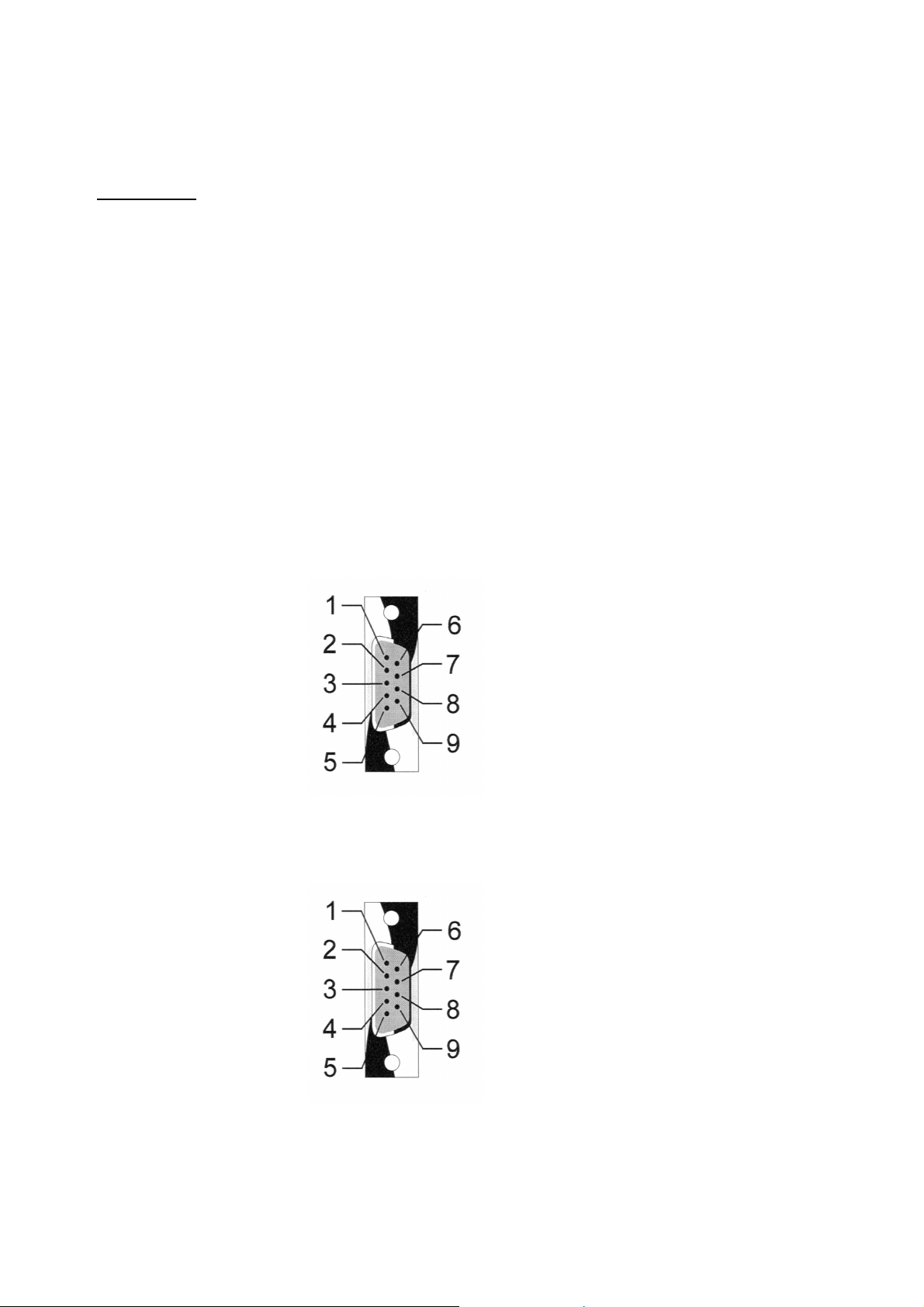
Stability control
Begin of
gas flow
Begin of
stability
control
Knew
K1
New begin
of stability
control
K1
Signal = Knew
Knew
2 * Deviation
Ti
Stability time Ts
Dead time Tt Time-out
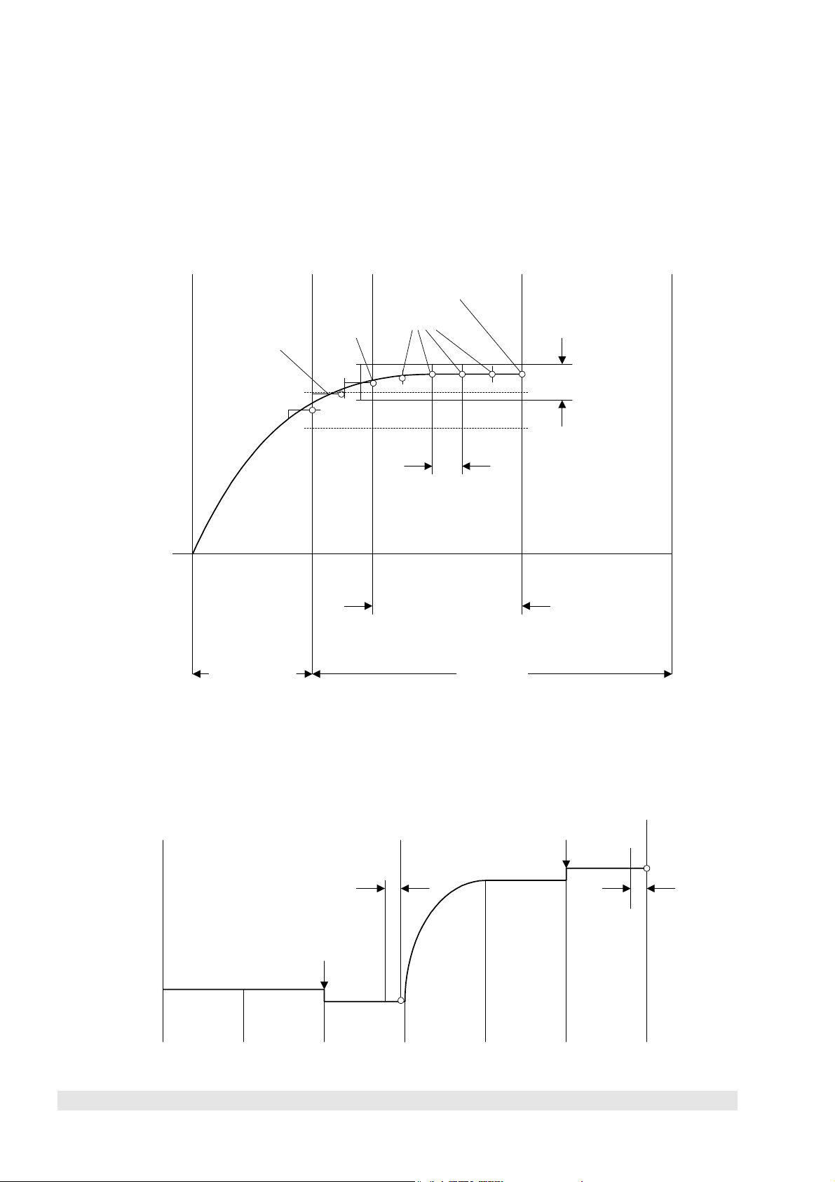
Stability controlled procedure of the zero/span calibration
Begin of the
function SATK
Calibration
Dead time Stability
time
Average over Ti,
Read with AANG
Ti Ti
Dead timeStability
time
Calibration
Stability
time
Stability
Average over Ti,
Read with AAEG
time
2 - 12
AK
90003752(3) [AK-Commands] 11/03
Page 39

II) V24/RS232/485 Interface - Single Analyzers and Systems
Only for platform: SCAL – Control command "Start system calibration"
To control the system calibration procedures the commands "SCAL", "STBY" and "ASTZ"
have to be used. With "SCAL" the procedures will be started. For more exact description of
procedures see also the "documentation of system calibration".
Starting condition: All attached analyzer module are in the stand-by mode ("AK STBY")
and the variable "CALSTAT" is "0".
Otherwise the response is "BUSY" (BS).
Control command
SCAL Kx m (n)
Optional parameters
Type of system calibration
Function associated to channel x
Code
m Kx n
0 = ZERO-CAL K0 n = 1: switch into test mode
1 = ZERO/SPAN-CAL K0
2 = PROGRAM K0 else: switch into normal mode
3 = TEST ZERO-GAS K1...999 time-out in sec
4 = TEST SPAN-GAS1 K1...999 time-out in sec
5 = TEST SPAN-GAS2 K1...999 time-out in sec
6 = TEST SPAN-GAS3 K1...999 time-out in sec
7 = TEST SPAN-GAS4 K1...999 time-out in sec
8 = TEST CLOSE GASES K1...999 time-out in sec
If optional parameter "n" is not in the command string the appropriate variable will not be
changed.
Stop command
90003752(1) [AK-Commands] 10/98
AK
2 - 13
Page 40

STBY K0
Function associated to the whole system unit
Code
Only using the channel number 0 (K0) will stop running "SYSCAL" procedure. Besides, all
procedures of the other analyzer modules will be stopped.
Response
SCAL 0
Error status
Code
Read command
ASTZ K0
Read of the whole FU
Code
With the command "ASTZ K0" it will be checked, if a system calibration is running or not.
"SCAL" will be sent back for a running system calibration. If no system calibration is
running this string will be missed.
2 - 14
AK
90003752(3) [AK-Commands] 11/03
Page 41

II) V24/RS232/485 Interface - Single Analyzers and Systems
SEGA – Control command "Spangas"
Starting this command the analyzers in a system or the single analyzer will switch on the
calibration valve to spangas and switch on the required pumps. This function will only
check the end point. It will not correct the calibration. If continuous line recorders will be
available, the paper transport will also be switched on.
Control command
SEGA K0
Function associated to the whole system unit
Code
SEGA K1 Kn
Function associated to channel n
Function associated to channel 1
Code
Response
SEGA 0
Error status
Code
90003752(1) [AK-Commands] 10/98
AK
2 - 15
Page 42

SEMB – Control command "Set range"
Starting this command the analyzers in a system or the single analyzer will set the range
that is named in the data. If the function "Autoranging" is running at that moment, it will be
stopped and the named range will be selected.
Control command
SEMB K1 M4 Kn M2
Function associated to channel n range 2
Function associated to channel 1 range 4
Code
Response
SEMB 0
Error status
Code
2 - 16
AK
90003752(3) [AK-Commands] 11/03
Page 43

II) V24/RS232/485 Interface - Single Analyzers and Systems
Only for CLD module: SENO/SNOX – Control command "Operation mode CLD"
Starting the command "SENO" the CLD analyzers in a system or the single CLD analyzer
will start the NO measurement. The command "SNOX" will start the NOx measurement.
Control command
SENO Kn
Function associated to channel n
Code for NO measurement
SNOX Kn
Function associated to channel n
Code for NOx measurement
Response
SENO 0
Error status
Code for NO measurement
SNOX 0
Error status
Code for NOx measurement
90003752(1) [AK-Commands] 10/98
AK
2 - 17
Page 44

SFRZ – Control command "Decimal point setup for floating point format"
E
N
With this command the format of real numbers will be setup.
This command will have an effect to the output of all real numbers. It is not possible to vary
it for different channels.
Control command
SFRZ K0 n
Parameter
Function associated to the whole system unit
Code
Description of parameter “n”
n = 1..9: n = number of digits after decimal point in normal floating point
format.
(f-notation of C-language's printf)
n = 11..19: (n-10) = is the maximum number of significant digits of either normal
floating point format or E-format, whichever is shorter.
(g-notation of C-language's printf).
Factory setting: n = 16 (= default).
Default is used if no other value for n is specified by a SFRZ
command.
n = 10 will set n = default
Response
SFRZ 0
Error status
Code
xample:
umber: 1234567.821
n = 2
Æ
1234567.82
n = 13
n = 15
Æ
1.23E06
Æ
1234600
2 - 18
AK
90003752(3) [AK-Commands] 11/03
Page 45

II) V24/RS232/485 Interface - Single Analyzers and Systems
SGTS – Control command "Device test"
Starting this command the analyzers in a system or the single analyzer will switch off the
calibration gas and the samplegas. That means, all gas tubes to the analyzer device will
be closed and the pumps will be switched off. Then, the device can be checked via a gas
input that is located directly in front of the device.
Control command
SGTS K0
Function associated to the whole system unit
Code
SGTS K1 Kn
Function associated to channel n
Function associated to channel 1
Code
Response
SGTS 0
Error status
Code
90003752(1) [AK-Commands] 10/98
AK
2 - 19
Page 46

SHDE – Control command "Hold status ON"
SHDA – Control command "Hold status OFF"
We have the possibility to activate the "Hold"-feature not only per calibration. We can do
this also by AK-Command "SHDE". With the command "SHDA" we have the possibility to
deactivate an activated "Hold" again. Starting the command "SHDE" will switch on the
"hold status". So it is possible to start the "Hold"-feature directly by AK command and not
only per calibration. With the "SHDA" command the "Hold status" will be deactivated.
Control command
SHDE K0
SHDA K0
Function associated to the whole system unit
Code
Response
SHDE 0
SHDA 0
Error status
Code
2 - 20
AK
90003752(3) [AK-Commands] 11/03
Page 47

II) V24/RS232/485 Interface - Single Analyzers and Systems
SINT – Control command "Integrator"
Starting this command the FU will activate the internal integrators. The previous calculated
and stored integral averages will be set to zero. The integrator will calculate new integral
averages as long as the control command "SINT" will be received again. The result of the
integrator can be read with the command "AIKG".
Control command
SINT K0
Function associated to the whole system unit
Code
SINT K1 Kn
Function associated to channel n
Function associated to channel 1
Code
Response
SINT 0
Error status
Code
90003752(1) [AK-Commands] 10/98
AK
2 - 21
Page 48

SLCH – Control command "Linearization check"
Starting this command the analyzers in a system or the single analyzer will switch on the
gas tubing to a gas distribution and a linearization procedure will run. The device will
record the correction values to the receiver specific raw curve. The deviations to the
correction values of the last determined linearization will be stored. Look at the command
"SLIN" for informations about the logic of the device control and of the gas distribution
control.
Control command
SLCH Kn Mn
Range n
Function associated to channel n
Code
Response
SLCH 0
Error status
Code
2 - 22
AK
90003752(3) [AK-Commands] 11/03
Page 49

II) V24/RS232/485 Interface - Single Analyzers and Systems
SLIN – Control command "Linearization"
Starting this command the analyzers in a system or the single analyzer will switch on the
gas tubing to a gas distribution. A linearization procedure for the selected range will run.
The device will record the determined correction values to the receiver specific raw curve.
The values will be stored in the device to calculate the gas concentration. This procedure
will be controlled by several commands of the TBCC or the system. The device or the gas
distribution will only accept those commands, it they have already received the "SLIN"
command. The "SLIN" command prepares the device or the gas distribution to receive and
execute further commands being necessary for the linearization procedure. The spangas
concentration has to be set up before by the "EKAK" command.
Control command
SLIN Kn Mn
Range n
Function associated to channel n
Code
Response
SLIN 0
Error status
Code
90003752(1) [AK-Commands] 10/98
AK
2 - 23
Page 50

SLST – Control command "Set linearization step"
Starting this command the gas distribution will switch on the named distribution step. The
device will work like described for the commands "SLIN" or "SLCH" depending on the
current procedure. The device will only accept the "SLST" command, if the commands
"SLIN" or "SLCH" were received before followed by the command "ELST".
Control command
SLST K1 n
Distribution step
Function associated to channel 1
Code
Response
SLST 0
Error status
Code
2 - 24
AK
90003752(3) [AK-Commands] 11/03
Page 51

II) V24/RS232/485 Interface - Single Analyzers and Systems
SMAN – Control command "Operation mode MANUAL"
With this command the FU will change to the operation mode "Manual". Then it will only be
possible to start functions from an operating unit integrated in the FU. The same operation
mode will be enabled, if the service switch of the FU will be in the position "Remote
Disable". In that mode it will only be possible to answer to read commands of the TBCC.
Control command
SMAN K0
Function associated to the whole system unit
Code
SMAN K1 Kn
Function associated to channel n
Function associated to channel 1
Code
Response
SMAN 0
Error status
Code
90003752(1) [AK-Commands] 10/98
AK
2 - 25
Page 52

SMGA – Control command "Samplegas"
Starting this command the analyzers in a system or the single analyzer will switch on the
sample gas valve and the pumps necessary for the samplegas transport. If continuous line
recorders will be available, the paper transport will also be switched on.
Control command
SMGA K0
Function associated to the whole system unit
Code
SMGA K1 Kn
Function associated to channel n
Function associated to channel 1
Code
Response
SMGA 0
Error status
Code
2 - 26
AK
90003752(3) [AK-Commands] 11/03
Page 53

II) V24/RS232/485 Interface - Single Analyzers and Systems
SNAB – Control command "Zerogas calibration"
Starting this command the analyzers in a system or the single analyzer will start a zerogas
calibration. The calibration gas flow will start automatically and the calibration procedure
will run. After this procedure will be over the system, the analyzer in a system or the single
analyzer will change to the stand-by mode. The running calibration procedure can be
canceled with the "STBY" command.
Control command
SNAB K0
Function associated to the whole system unit
Code
SNAB K1 Kn
Function associated to channel n
Function associated to channel 1
Code
Response
SNAB 0
Error status
Code
90003752(1) [AK-Commands] 10/98
AK
2 - 27
Page 54

SNGA – Control command "Zerogas"
Starting this command the analyzers in a system or the single analyzer will switch on the
zerogas valve and the pumps necessary for the zerogas transport. This function will only
check the zero point. It will not correct the calibration. If continuous line recorders will be
available, the paper transport will also be switched on.
Control command
SNGA K0
Function associated to the whole system unit
Code
SNGA K1 Kn
Function associated to channel n
Function associated to channel 1
Code
Response
SNGA 0
Error status
Code
2 - 28
AK
90003752(3) [AK-Commands] 11/03
Page 55

II) V24/RS232/485 Interface - Single Analyzers and Systems
SPAB – Control command "Spangas calibration"
Starting this command the analyzers in a system or the single analyzer will start a spangas
calibration. The calibration gas flow will start automatically and the calibration procedure
will run. After this procedure will be over the system, the analyzer in a system or the single
analyzer will change to the stand-by mode. The running calibration procedure can be
canceled with the "STBY" command.
Control command
SPAB K0
Function associated to the whole system unit
Code
SPAB K1 Kn
Function associated to channel n
Function associated to channel 1
Code
Response
SPAB 0
Error status
Code
90003752(1) [AK-Commands] 10/98
AK
2 - 29
Page 56

SPAU – Control command "Pause"
With this command the FU will be set to a defined status of interruption. This command will
only be accepted, if the FU is already in the stand-by mode. The "SPAU" command will
switch off the operation modes (e.g. FID flame, pump of an NO device) or the
corresponding setpoints (e.g. temperature of the hot pipe). With the control command
„Reset“ or „Stand-by“ the FU will change to the stand-by mode to get ready for operation.
The real functionality of the "SPAU" command will depend on the used FU. It is part of
each device or system specification.
Control command
SPAU K0
Function associated to the whole system unit
Code
SPAU Kn
Function associated to channel n
Code
Response
SPAU 0
Error status
Code
2 - 30
AK
90003752(3) [AK-Commands] 11/03
Page 57

II) V24/RS232/485 Interface - Single Analyzers and Systems
SQEF – Control command "Cross interference"
Starting this command the CO analyzer will measure wet C02. It will be produced by
streaming three percent C02 through water bottles at 20 degrees Celsius. The CO
analyzer will measure this gas mixture. The signal will be stored in the analyzer. It can be
read by the TBCC with the "AQEF" command. The measured concentration has to be
maximum 3 ppm for ranges smaller than 300 ppm. For bigger ranges it has to be
maximum 1 % of the end of range value. These limits will be controlled by the TBCC.
Control command
SQEF Kn
Function associated to channel n
Code
Response
SQEF 0
Error status
Code
90003752(1) [AK-Commands] 10/98
AK
2 - 31
Page 58

SREM – Control command "Remote"
With this command the FU will change to the computing operation mode. Then, the
function start will only be possible by the TBCC. This operation mode may only be set, if
the service switch of the FU is in the position "Remote Enable".
Control command
SREM K0
Function associated to the whole system unit
Code
SREM K1 Kn
Function associated to channel n
Function associated to channel 1
Code
Response
SREM 0
Error status
Code
2 - 32
AK
90003752(3) [AK-Commands] 11/03
Page 59

II) V24/RS232/485 Interface - Single Analyzers and Systems
SRES – Control command "Reset"
With this command the FU will get a software reset. This command has the same effect to
the FU like the switching off and on of the power supply. All running procedures will be
canceled. An initializing will be started, e.g. check and control of temperature setpoints.
After that the operation modes "Manual" and "Stand-by" will be enabled.
Control command
SRES K0
Function associated to the whole system unit
Code
SRES Kn
Function associated to channel n
Code
Response
SRES 0
Error status
Code
90003752(1) [AK-Commands] 10/98
AK
2 - 33
Page 60

SRON – Control command "Delay modus ON"
SROF – Control command "Delay modus OFF"
Starting this command the analyzers in a system or the single analyzer will determine
measurement and integral values (averages), that will be delayed according to the delay
time of the write command "EVEZ". The read commands "AKON", "AIKO" and "AIKG" will
get an old value according to the synchronization time of the command "EVEZ". The
analog output will get the same delay. With the command "Delay modus OFF" the
integrators will start immediately and the measurement and integral values will be
determined and sent out without delay.
Control command
SRON K0
SROF K0
Function associated to the whole system unit
Code
SRON Kn
SROF Kn
Function associated to channel n
Code
Response
SRON 0
SROF 0
Error status
Code
2 - 34
AK
90003752(3) [AK-Commands] 11/03
Page 61

II) V24/RS232/485 Interface - Single Analyzers and Systems
SSPL – Control command "Purging"
Starting this command the analyzers in a system or the single analyzer will switch on the
purge gas valve and the pumps necessary for the purge gas transport.
This function can be finished either by a new command or by a defined time interval. After
the purging will be over the system, the analyzer in a system or the single analyzer will
change to the stand-by mode.
Control command
SSPL K0
Function associated to the whole system unit
Code
SSPL Kn
Function associated to channel n
Code
Response
SSPL 0
Error status
Code
90003752(1) [AK-Commands] 10/98
AK
2 - 35
Page 62

ST9O – Control command "Set t90 time step"
With this command the analyzer will use the t90 time according to the current step. The
abbreviation "S" means fast time, "M" means medium time and "L" means slow time. After
the switching on of the device or after a "Reset" the fastest time will be set.
Control command
ST9O K1 S
Function associated to channel 1, fast time
Code
Response
ST9O 0
Error status
Code
2 - 36
AK
90003752(3) [AK-Commands] 11/03
Page 63

II) V24/RS232/485 Interface - Single Analyzers and Systems
STBY – Control command "Stand-by"
With the command "Stand-by" the FU will be set to a defined status of interruption.
Running functions like measuring or purging will be canceled. Then, the stand-by mode will
be enabled. The ranges will keep selected. The FU will get ready for measurement and
operating, no matter which mode was the previous.
Control command
STBY Kn
Function associated to the whole system unit
Code
Response
STBY 0
Error status
Code
90003752(1) [AK-Commands] 10/98
AK
2 - 37
Page 64

2 - 38
AK
90003752(3) [AK-Commands] 11/03
Page 65

II) V24/RS232/485 Int e r f a c e - Single Analy zers and Sy stems
4. Description of all Read Commands
AAEG – Read command "Deviation to spangas"
To this read command the analyzers in a system or the single analyzer will send to the
TBCC the following data for the called channel (device):
∗ The measured and stored signal of the last spangas measurement.
∗ The deviation from the setpoint value of the linearized curve in ppm and percent,
referred to the end of range value.
Spangas measurement: Signal after the end of the functions "Automatic calibration" or
"Spangas", stability controlled or time controlled depending on the setup in "EFDA".
Read command
AAEG K0
AAEG Kn
Read of the whole system unit
Code
Response
AAEG 0 M1 XXX YYY ZZ ... Mn XXX YYY ZZ
Deviation [%]
Deviation [ppm]
Signal [ppm]
Range n
Deviation [%]
Deviation [ppm]
Signal [ppm]
Range 1
Error status
Code
The values will get the same format for the read of single channels.
90003752(1) [AK-Commands] 10/98
AK
2 - 39
Page 66

AALI – Read command "Deviations of the last linearization check with spangas"
To this read command the analyzers in a system or the single analyzer will send to the
TBCC the following data for the called channel (device) and subchannel (range):
∗ The determined and stored deviations in ppm of the last linearization check with
spangas.
Read command
AALI Kn Mx
Read of channel n and range x
Code
Response
AALI 0 AAA BBB ...... XXX
xth difference
2nd difference
1st difference
Error status
Code
2 - 40
AK
90003752(1) [AK-Commands] 10/98
Page 67

II) V24/RS232/485 Int e r f a c e - Single Analy zers and Sy stems
AANG – Read command "Deviation to zerogas"
To this read command the analyzers in a system or the single analyzer will send to the
TBCC the following data for the called channel (device):
∗ The determined and stored signal of the last zerogas measurement with its range.
∗ The deviation from the setpoint value of the linearized curve in ppm and percent,
referred to the end of range value.
Zerogas measurement: Signal after the end of the functions "Automatic calibration" or
"Zerogas", stability controlled or time controlled depending on the setup in "EFDA".
Read command
AANG K0
AANG Kn
Read of the whole system unit
Code
Response
AANG 0 M1 XXX YYY ZZ ... Mn XXX YYY ZZ
Deviation [%]
Deviation [ppm]
Signal [ppm]
Range n
Deviation [%]
Deviation [ppm]
Signal [ppm]
Range 1
Error status
Code
The values will get the same format for the read of single channels.
90003752(1) [AK-Commands] 10/98
AK
2 - 41
Page 68

ABST – Read command "Counter of operating hours"
To this read command the FU will send to the TBCC the following data:
∗ The operating hours until now for the roots fan, the turbo compressor, the sampling
pumps etc. The operating hours will only be sent as integers.
Read command
ABST K0
Read of the whole system unit
Code
Response
ABST 0 T1 T2 ... Tn
Value of each hour of operation
Error status
Code
2 - 42
AK
90003752(1) [AK-Commands] 10/98
Page 69

II) V24/RS232/485 Int e r f a c e - Single Analy zers and Sy stems
ADRU – Read command "Pressure"
To this read command the analyzers in a system or the single analyzer will send to the
TBCC the following data for the called channel (device) and if need be for the subchannel
(pressure measurement):
∗ The signal in Pascal.
Note: At the moment no subchannels will be used.
Read command
ADRU K0
ADRU Kn (m)
Read of channel n (and subchannel m)
Code
Response
ADRU 0 XXX
Pressure value
Error status
Code
90003752(1) [AK-Commands] 10/98
AK
2 - 43
Page 70

ADUF – Read command "Flow"
To this read command the analyzers in a system or the single analyzer will send to the
TBCC the following data for the called channel (device) and subchannel (flow
measurement):
∗ The signal in liter per time unit.
Read command
ADUF K0
ADUF Kn (m)
Read of channel n (and subchannel m)
Code
Response
ADUF 0 XXX
Flow value
Error status
Code
2 - 44
AK
90003752(1) [AK-Commands] 10/98
Page 71

II) V24/RS232/485 Int e r f a c e - Single Analy zers and Sy stems
AEMB – Read command "Selected range"
To this read command the analyzers in a system or the single analyzer will send to the
TBCC the following data for the called channel (device):
∗ The selected and used range at this moment.
Read command
AEMB K0
AEMB Kn
Read of channel n
Code
Response
AEMB 0 Mn
Range with setup
Error status
Code
90003752(1) [AK-Commands] 10/98
AK
2 - 45
Page 72

AFDA – Read command "Function length"
To this read command the FU will send to the TBCC the following data for the called
channel (device):
∗ The function or procedure times of the function determined in "CODE".
Functions like "SATK", "SLIN", "SLCH", "SALI", "SQEF", "SNGA" or "SEGA" will run time
controlled according to the times T1 to T4 or stability controlled.
Time control: If only T1 is set or if T2 = 0, time control will run with step time T1
(total function time).
Stability control: Times T1 to T4 have to be set.
Read command
AFDA K0 CODE
AFDA Kn CODE
Code for the function
Read of channel n
Code
Response
AFDA 0 T1 (T2 T3 T4)
"Time out"; after this time is over, the procedure will be
canceled and you will get an error message; this time will
start after the wait.
Integration time to get the mean value of one signal.
Stability time: All signals have to be in a certain tolerance
during this time.
Time to wait for: after the switching on resp. changing of
gases or the stepping time of time control.
Error status
Code
2 - 46
AK
90003752(1) [AK-Commands] 10/98
Page 73

II) V24/RS232/485 Int e r f a c e - Single Analy zers and Sy stems
AGID – Read command "Device identification"
To this read command the gas analyzer will send to the TBCC a text string consisting of
several data. These data will be separated by a slash ( / ).
Read command
AGID K0
Read of the whole system unit
Code
Response
AGID 0 a/b/c
Device identification a = Name and serial number
b = Program version
c = Date
Error status
Code
90003752(1) [AK-Commands] 10/98
AK
2 - 47
Page 74

AGRW – Read command "Limits"
To this read command the analyzers in a system or the single analyzer will send to the
TBCC the following data for the called channel (device):
∗ The corresponding limits, e.g. maximum deviations of calibration.
Read command
AGRW K0 m
AGRW Kn m
Read of channel n and subchannel m
m = 0: Zerogas calibration
m = 1: Spangas calibration
Code
Response
AGRW 0 XXX
Limit
Error status
Code
2 - 48
AK
90003752(1) [AK-Commands] 10/98
Page 75

II) V24/RS232/485 Int e r f a c e - Single Analy zers and Sy stems
AIKG – Read command "Concentration integral value; all"
To this read command the FU will send to the TBCC the following data:
∗ The corrected average signal valid at that moment (e.g. analyzed value), that has been
calculated since the last "SINT" command. The physical parameter is described in the
section about FU. The value will be limited to six relevant digits, because it is useless to
send gas concentrations in an accuracy less than pars pro mille. Look at the example of
the "AKON" command !
Cf. the "SFRZ" command !
Read command
AIKG K0
Read of the whole system unit
Code
AIKG K1 ... Kn
Read of channel n
Read of channel 1
Code
90003752(1) [AK-Commands] 10/98
AK
2 - 49
Page 76

Response
AIKG 0 123400 12340 1234 123.4 12.34 -1.23 #
Channel 7 no signal,
invalid or range
overflow/underflow
Channel 6 negative value
1 digit before/ 2 digits after
decimal point.
Channel 5 positive value
2 digit before / 2 digits after
decimal point.
Channel 4 positive value
3 digits before / 1 digit after
decimal point.
Channel 3 positive value
4 digits
Channel 2 positive value
5 digits
Channel 1 positive value
6 digits
Error status
Code
The values will get the same format for the read of single channels.
2 - 50
AK
90003752(1) [AK-Commands] 10/98
Page 77

II) V24/RS232/485 Int e r f a c e - Single Analy zers and Sy stems
AIKO – Read command "Concentration integral value"
To this read command the FU will send to the TBCC the following data:
∗ The corrected average signal valid at that moment (e.g. analyzed value), that has been
calculated since the last "SINT" command resp. the last "AIKO" command. The physical
parameter is described in the section about FU. The value will be limited to six relevant
digits, because it is useless to send gas concentrations in an accuracy less than pars
pro mille. Look at the example of the "AKON" command !
Read command
AIKO K0
Read of the whole system unit
Code
AIKO K1 ... Kn
Read of channel n
Read of channel 1
Code
90003752(1) [AK-Commands] 10/98
AK
2 - 51
Page 78

Response
AIKO 0 123400 12340 1234 123.4 12.34 -1.23 #
Channel 7 no signal,
invalid or range
overflow/underflow
Channel 6 negative value
1 digit before/ 2 digits after
decimal point.
Channel 5 positive value
2 digit before / 2 digits after
decimal point.
Channel 4 positive value
3 digits before / 1 digit after
decimal point.
Channel 3 positive value
4 digits
Channel 2 positive value
5 digits
Channel 1 positive value
6 digits
Error status
Code
The values will get the same format for the read of single channels.
2 - 52
AK
90003752(1) [AK-Commands] 10/98
Page 79

II) V24/RS232/485 Int e r f a c e - Single Analy zers and Sy stems
AKAK – Read command "Calibration gas concentration"
To this read command the analyzers in a system or the single analyzer will send to the
TBCC the following data for the called channel (device) and range:
∗ The calibration gas concentration in ppm.
Read command
AKAK Kn [Mx]
Range number (optional); x = 1, 2, 3, 4
Output of all ranges,
if no range is named.
Read of channel n
Code
Response
AKAK 0 M1 XXX M2 XXX ... Mn ZZZ
Concentration of calibration gas
Range n
Concentration of calibration gas
Range 2
Concentration of calibration gas
Range 1
Error status
Code
The values will get the same format for the read of single ranges.
90003752(1) [AK-Commands] 10/98
AK
2 - 53
Page 80

AKAL – Read command "Stored calibration corrections"
To this read command the analyzers in a system or the single analyzer will send to the
TBCC the following data for the called channel (device):
∗ The corrections in ppm determined and stored during the last calibration. These
corrections are also necessary to calculate the analyzer values (deviations from the
linearized curve).
∗ The sum of deviations (total correction) to the calibration before the last linearization
check for the last range calibrated with zero and spangas.
Read command
AKAL K0 [Mx]
AKAL Kn [Mx]
Range number (optional); x = 1, 2, 3, 4
Output of all ranges,
if no range is named.
Read of channel n
Code
2 - 54
AK
90003752(1) [AK-Commands] 10/98
Page 81

II) V24/RS232/485 Int e r f a c e - Single Analy zers and Sy stems
Response
AKAL 0 M1 aaa kk AAA KK ..... Mn xxx ff XXX FF
Deviation of the
final point value
Correction for the
final point
Deviation of the
zero value
Correction for the
zero point
nth range
Deviation of the
final point value
Correction for the
final point
Deviation of the
zero value
Correction for the
zero point
1st range
Error status
Code
90003752(1) [AK-Commands] 10/98
AK
2 - 55
Page 82

AKEN – Read command "Device tag"
To this read command the FU will send to the TBCC the tag for the called channel
(device).
Read command
AKEN K0
AKEN Kn
Read of channel n
Code
Response
AKEN 0 XXX..X
Device tag
Error status
Code
2 - 56
AK
90003752(1) [AK-Commands] 10/98
Page 83

II) V24/RS232/485 Int e r f a c e - Single Analy zers and Sy stems
AKFG – Read command "Configuration of the system"
To this read command the system will send to the TBCC the following data:
∗ The adjustment about the channels (analyzers or virtual channels) that are expected to
send the current signals and the corresponding sequence.
∗ The channels that can be called with the total channel command "K0". That means:
Which devices can be included with "K0" or "KV Ln" to operation modes like measuring,
zerogas and spangas.
∗ Which channel will analyze which chemical component.
∗ The sequence in which the signals of analyzers or calculated values from virtual
channels will be sent to the total channel read command "K0" or "KV Ln". This
information will be done by the string "XYZ" standing for each component, e.g. C0, N0,
, BRETT (Lambda according to Brettschneider) etc.
NO
x
Read command
AKFG K0
AKFG KV Ln
Read of the whole system unit resp.
some defined lines
Code
Response
AKFG 0 XYZ Kn XYZ Km XYZ Kx
Selected channel x, component XYZ
Selected channel m, component XYZ
Selected channel n, component XYZ
Error status
Code
90003752(1) [AK-Commands] 10/98
AK
2 - 57
Page 84

AKON – Read command "Signal" (measured concentration value)
To this read command the analyzers in a system or the single analyzer will send to the
TBCC the following data:
∗ The corrected signal (concentration value) valid at that moment. Normally the physical
unit is ppm. The value will be limited to six relevant digits, because it is useless to send
gas concentrations in an accuracy less than pars pro mille.
Example for four relevant digits (default: six digits):
measured
conc. [ppm]
sent
conc. [ppm]
123456 123500
12356 12360
1234.4 1234
123.45 123.5
12.56 12.56
1.23 1.23
Cf. the "SFRZ" command !
Read command
AKON K0
Read of the whole system unit
Code
AKON K1 .... Kn
Read of channel n
Read of channel 1
Code
2 - 58
AK
90003752(1) [AK-Commands] 10/98
Page 85

II) V24/RS232/485 Int e r f a c e - Single Analy zers and Sy stems
Response
AKON 0 123400 12340 1234 123.4 12.34 -1.23 #
Channel 7 no signal,
invalid or range
overflow/underflow
Channel 6 negative value
1 digit before/ 2 digits after
decimal point.
Channel 5 positive value
2 digit before / 2 digits after
decimal point.
Channel 4 positive value
3 digits before / 1 digit after
decimal point.
Channel 3 positive value
4 digits
Channel 2 positive value
5 digits
Channel 1 positive value
6 digits
Error status
Code
The values will get the same format for the read of single channels.
90003752(1) [AK-Commands] 10/98
AK
2 - 59
Page 86

AKOW – Read command "Correction for zerogas calibration and gradient"
To this read command each analyzer in a system or the single analyzer will send to the
TBCC the following data:
∗ The correction of the last zero calibration and the gradient of the calibration curve.
Read command
AKOW K0 Mx
AKOW Kn Mx
Read of channel n range x
Code
Response
AKOW 0 XXX YYY
Steepness of the calibration curve
Correction of the zero calibration
Error status
Code
2 - 60
AK
90003752(1) [AK-Commands] 10/98
Page 87

II) V24/RS232/485 Int e r f a c e - Single Analy zers and Sy stems
ALCH – Read command "Deviations of the last linearization check"
To this read command the analyzers in a system or the single analyzer will send to the
TBCC the following data for the called channel (device) and subchannel (range):
∗ The determined and stored deviations of the last linearization check in ppm.
∗ The information if these deviations will be in the lawful tolerances. That means: Is the
check o.k. or not ?
Read command
ALCH Kn Mx
Read of channel n and range x
Code
Response
ALCH 0 IO AAA BBB ... XXX
xth difference
2nd difference
1st difference
Checked result is o.k. (otherwise NO)
Error status
Code
90003752(1) [AK-Commands] 10/98
AK
2 - 61
Page 88

Only for MLT analyzers: ALIK – Read command "Output of the linearization curve"
To this read command the x/y values of the linearization curve will be sent. With this
values can be determined the desired segment of the linearization curve and the interval
between the function values.
Read command
ALIK Kn a b c
Interval between the function values [ppm]
End concentration of the segment [ppm]
Beginning concentration of the segment [ppm]
Read of channel n
Only one channel can be checked (no K0).
Code
Response
ALIK s y1 x1 y2 x2 y3 x3...
Raw value No. 3
Setpoint value No. 3
Raw value No. 2
Setpoint value No. 2
Raw value No. 1
Setpoint value No. 1
Error status
Code
2 - 62
AK
90003752(1) [AK-Commands] 10/98
Page 89

II) V24/RS232/485 Int e r f a c e - Single Analy zers and Sy stems
ALIN – Read command "Linearization values" (X/Y = Setpoint / Raw value)
To this read command the analyzers in a system or the single analyzer will send to the
TBCC the following data for the called channel (device) and subchannel (range):
∗ The determined and stored setpoint/raw values of the last linearization.
Read command
ALIN Kn [Mx]
This information is optional. It will not be evaluated, because
the values are valid for all ranges.
Read of channel n and range x
Code
Response
ALIN 0 aaa AAA bbb BBB ...... xxx XXX
nth pair of values
2nd pair of values
1st pair of values
Error status
Code
90003752(1) [AK-Commands] 10/98
AK
2 - 63
Page 90

ALKO – Read command "Polynomial coefficients of the linearization curve"
The coefficients of the linearization polynomial calculated by the analyzer linearization will
be transferred. These coefficients will be enabled using the polynomial method to linearize.
Read command
ALKO Kn Mm
Read of channel n and range m
Code
Response
ALKO 0 Mm a0 a1 a2 a3...
Coefficients of the polynomial
Range m
Error status
Code
2 - 64
AK
90003752(1) [AK-Commands] 10/98
Page 91

II) V24/RS232/485 Int e r f a c e - Single Analy zers and Sy stems
ALST – Read command "Linearization steps"
To this read command the gas distribution will send to the TBCC or to the system the
following data:
∗ The numbers and the division in percent of the distribution steps (maximum two digits
after decimal point).
This command will only be accepted by the gas distribution, if the commands "SLIN" or
"SLCH" have been received before.
Read command
ALST Kn
Read of the gas distribution
Code
Response
ALST 0 1 XY 2 XY ... n XY
Last distribution step n, division XY %
2nd distribution step, division XY %
1st distribution step, division XY %
Error status
Code
90003752(1) [AK-Commands] 10/98
AK
2 - 65
Page 92

AM90 – Read command "Actual response time (t90)"
To this read command the analyzer will send the t90 time in seconds that is enabled to
calculate the concentration for the called channel at the moment.
Cf. "AT90", "ET90", "ST90" and "EM90"
Read command
AM90 Kn
Read of channel n
Code
Response
AM90 0 a
t
time (response time) [s]
90
Error status
Code
2 - 66
AK
90003752(1) [AK-Commands] 10/98
Page 93

II) V24/RS232/485 Int e r f a c e - Single Analy zers and Sy stems
AMBA – Read command "Begin of range"
To this read command the analyzers in a system or the single analyzer will send to the
TBCC the following data for the called channel (device):
∗ The begin of range values in ppm.
Read command
AMBA K0 [Mx]
AMBA Kn [Mx]
Range number (optional)
Read of channel n
Code
Response
AMBA 0 Mx XXX
Begin of range x
Range No. x
Error status
Code
The values will get the same format for the read of single channels.
90003752(1) [AK-Commands] 10/98
AK
2 - 67
Page 94

AMBE – Read command "End of range"
To this read command the analyzers in a system or the single analyzer will send to the
TBCC the following data for the called channel (device):
∗ The end of range values in ppm.
Read command
AMBE K0 [Mx]
AMBE Kn [Mx]
Range number (optional)
Read of channel n
Code
Response
AMBE 0 Mx XXX
End of range x
Range No. x
Error status
Code
The values will get the same format for the read of single channels.
2 - 68
AK
90003752(1) [AK-Commands] 10/98
Page 95

II) V24/RS232/485 Int e r f a c e - Single Analy zers and Sy stems
AMBU – Read command "Switching values for autoranging"
To this read command the analyzers in a system or the single analyzer will send to the
TBCC the following data for the called channel (device):
∗ The adjusted switching values in ppm for a changing of ranges with autoranging.
Read command
AMBU K0
AMBU Kn
Read of channel n
Code
Response
AMBU 0 M1 xxx XXX M2 yyy YYY Mn zzz ZZZ
Switch on value of range n
Switch off value of range n
Range No. n
Switch on value of range 2
Switch off value of range 2
Range No. 2
Switch on value of range 1
Switch off value of range 1
Range No. 1
Error status
Code
The values will get the same format for the read of single channels.
90003752(1) [AK-Commands] 10/98
AK
2 - 69
Page 96

AMDR – Read command "Manual adjusted pressure"
To this read command the gas analyzer will send the value adjusted for the parameter.
This value will be useful, if no pressure measurement will be installed in the analyzer.
Read command
AMDR Kn
Read of channel n
Code
Response
AMDR 0 a
Pressure [Pa]
Error status
Code
The values will get the same format for the read of single channels.
2 - 70
AK
90003752(1) [AK-Commands] 10/98
Page 97

II) V24/RS232/485 Int e r f a c e - Single Analy zers and Sy stems
AQEF – Read command "Cross interference"
To this read command the CO analyzer or the system will send to the TBCC:
∗ The concentration value in ppm determined and stored in the analyzer. This value will
be stored in the device until a new cross interference will be determined by the "SQEF"
command. The TBCC will control, if limits will be exceeded. The TBCC will also start
actions if necessary.
Read command
AQEF Kn
Read of channel n
Code
Response
AQEF 0 XXX
Interference [ppm]
Error status
Code
90003752(1) [AK-Commands] 10/98
AK
2 - 71
Page 98

ASOL – Read command "Setpoint value with limits"
To this read command the FU will send to the TBCC the following data for the called
channel (FU) and subchannel (e.g. heating):
∗ The adjusted setpoints with deviation limits for error reports.
For the actual used devices subchannel "m" will be:
m = 0 Concentration
m = 1 Temperature
m = 2 Pressure
m = 3 Flow
m = 4 Pocket calculator No. 1
m = 5 Pocket calculator No. 2
m = 6 Pocket calculator No. 3
m = 7 Pocket calculator No. 4
These assignations may be changed for devices used in the future !
Read command
ASOL K0 m
ASOL Kn m
Read of channel n and subchannel m
Code
Response
ASOL 0 WWW xxx XXX
Upper limit
Lower limit
Setpoint value
Error status
Code
2 - 72
AK
90003752(1) [AK-Commands] 10/98
Page 99

II) V24/RS232/485 Int e r f a c e - Single Analy zers and Sy stems
ASTA – Read command "General status of the system"
To this read command the FU will send to the TBCC:
∗ All channels of the FU with any error in their status at that moment. A detailed
description of the errors will not be sent to this read command. It is only possible to read
channel No. 0.
Read command
ASTA K0
Read of channel zero
Code
Response
ASTA 7 K1 K4 Kn
Channel n with error status
Channel 4 with error status
Channel 1 with error status
Error status
Code
90003752(1) [AK-Commands] 10/98
AK
2 - 73
Page 100

ASTF – Read command "Error status"
To this read command the FU will send to the TBCC:
∗ All error existing at that moment in the called channel (FU). The description of the error
characterization is specific for each device. It will be symbolized with a number. A
reading to "K0" will get the errors of devices that are not assigned to single channels
(e.g. samplegas cooler).
Read command
ASTF Kn
Read of channel n
Code
Response
ASTF 7 XXX YYY ... NNN
nth error number
2nd error number
1st error number
Error status
Code
2 - 74
AK
90003752(1) [AK-Commands] 10/98
 Loading...