

Page 1

Quick Reference Guide
P/N 3300995, Rev. C
April 2003
Model 3500 Transmitter
(9-wire) or
Model 3300 Peripheral
Installation Instructions for
Rack-Mount
For online technical support, use the EXPERT2™ system
at www.expert2.com. To speak to a customer service
representative, call the support center nearest you:
• In the U.S.A., phone 1-800-522-MASS
(1-800-522-6277)
• In Canada and Latin America, phone
(303) 530-8400
• In Asia, phone (65) 6770-8155
• In the U.K., phone 0800 - 966 180 (toll-free)
• Outside the U.K., phone +31 (0) 318 495 67
Micro Motion
TM
Page 2

BEFORE YOU BEGIN
This quick reference guide explains basic installation guidelines for
®
mounting the Micro Motion
Model 3300/3500 applications platform in a
19-inch (486,2 mm) rack.
For information on I.S. applications, refer to Micro Motion ATEX, UL,
or CSA installation instructions.
For complete instructions about configuration, maintenance, and service,
refer to the instruction manual shipped with the transmitter.
WARNING
Improper installation in a hazardous area can cause
an explosion.
For information about hazardous applications, refer to
Micro Motion ATEX, UL, or CSA installation instructions,
shipped with the transmitter or available from the Micro
Motion web site.
WARNING
Hazardous voltage can cause severe injury or death.
Install transmitter and complete all wiring before
supplying power.
CAUTION
Improper installation could cause measurement error
or flowmeter failure.
Follow all instructions to ensure transmitter will operate
correctly.
©2003, Micro Motion, Inc. All rights reserved. Micro Motion is a registered trademark of Micro Motion, Inc. The Micro
Motion and Emerson logos are trademarks of Emerson Electric Co. All other trademarks are property of their respective
owners.
1
Page 3

European installations
This Micro Motion product complies with all applicable European
directives when properly installed in accordance with the instructions in
this quick reference guide. Refer to the EC declaration of conformity for
directives that apply to this product.
The EC declaration of conformity, with all applicable European
directives, and the complete ATEX Installation Drawings and Instructions
are available on the internet at www.micromotion.com/atex or through
your local Micro Motion support center.
Installation kit
For mounting in a rack, the Model 3300/3500 installation kit includes the
following parts:
• One DIN standard 41612, Type D connector for input/output wiring,
with solder tails or screw terminals
• (Model 3500 only) One DIN standard 41612, keyed Type D connector
for sensor wiring, with solder tails or screw terminals
• One plug-in connector for power supply wiring
• Four (Model 3300) or six (Model 3500) slotted cheese-head machine
screws, size M2.5x8, for securing wiring connectors to the rack
STEP 1. Choosing a location
Choose a location for the transmitter based on the requirements described
below.
Environmental requirements
Install the transmitter where ambient temperature is between
–4 and
+140 °F (–20 and +60 °C).
If multiple applications platforms are installed, provide at least 1 U
(1 HE) of vertical space between racks to ensure proper ventilation. See
Figure 1, page 3.
2
Page 4
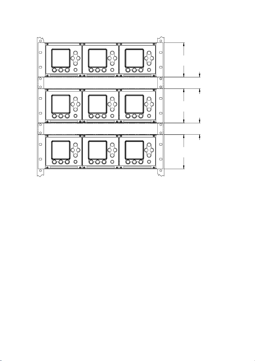
Figure 1. Space requirements for proper ventilation
1 U = 1 HE = 1.750 inches (44,5 mm)
3 U (3 HE)
1 U (1 HE)
3 U (3 HE)
1 U (1 HE)
3 U (3 HE)
Dimensions
The Model 3300/3500 has the following dimensions (see Figure 2,
page 4):
• Height: 128 mm (3 U or 3 HE)
• Width: 142 mm (28 HP or 28 TE)
• Depth: 160 mm
The Model 3300/3500 conforms to DIN standard 41494, Part 5
(IEC 297-3) for 19-inch (486,2 mm) racks. Up to three enclosures fit into
one rack. See Figure 1.
3
Page 5

Figure 2. Dimensions for mounting in rack
1 U = 1 HE = 1.750 inches (44,5 mm)
1 HP = 1 TE = 0.200 inch (5,1 mm)
inches
(mm)
3 U
(3 HE)
4 13/16
(122,5)
19-inch (486,2 mm) rack conforms to DIN 41494, Part 5, and IEC 297-3.
Not included with Model 3300/3500.
Rear rail for mounting connectors
that conform to DIN 41612 and IEC 603-2.
Not included with Model 3300/3500.
inches
(mm)
Approvals tag
25 HP
(25 TE)
5.6
(142,2)
28 HP (28 TE)
Optional screw terminal
4 x M2.5x11
5 1/16
(128,5)
Intrinsic
safety
shield
(Model
3500 only)
1
(25,4)
6 11/16
(169,9)
7 29/32
(200,6)
7 11/32
(186,7)
8 33/64
(216,2)
Flowmeter cable lengths
Maximum cable length from the sensor to the Model 3500 transmitter is
1000 feet (300 meters).
If you are installing the Model 3300 applications peripheral in
combination with a transmitter, the maximum cable length from the
transmitter’s frequency output to the Model 3300’s frequency input is
500 feet (150 meters).
4
Page 6

STEP 2. Installing guide rails and wiring connectors
Guide rails
Positions of guide rails and wiring connectors are indicated in Figure 3,
page 6. Centers of guide rails should be 27 HP (27 TE) apart, for
example, at 1 HP (TE) and 28 HP (TE).
Wiring connectors
The applications platform is shipped with a solder-tail or screw-type
connector for input/output wiring, a keyed solder-tail or screw-type
connector for sensor wiring (Model 3500 only), and a plug-in connector
for power supply wiring.
Working from the front of the rack, use the supplied M2.5x8 screws to
install the wiring connectors onto the back of the rack as follows:
1. Use the centers of the guide rails as reference points and refer to
Figure 3, page 6.
2. Install the input/output wiring connector at 4 HP (4 TE) from the
neighboring unit or from the edge of the rack.
3. (Model 3500 only) Install the keyed sensor wiring connector at 16 HP
(16 TE) from the neighboring unit or from the edge of the rack.
4. Install the power supply wiring connector at 25 HP (25 TE) from the
neighboring unit or from the edge of the rack.
5
Page 7

Figure 3. Positions of guide rails and wiring connectors
Guide rail centers should be 27 HP (27 TE) apart;
for example, 1 HP (1 TE) and 28 HP (28 TE)
Install screws and connectors from front of
rack.
• Model 3500 has six M2.5x8 screws
and three connectors.
• Model 3300 has four M2.5x8 screws
and two connectors.
Front
connector is 4 HP (4 TE)
from neighboring unit or
Input/output wiring
from edge of rack
Back
Power supply wiring
connector is 25 HP (25 TE)
from neighboring unit or
from edge of rack
Keyed sensor wiring
connector is 16 HP (16 TE)
from neighboring unit or from
edge of rack
Keys on sensor
wiring connector
M2.5x8
STEP 3. Installing the Model 3300/3500 in the rack
1. Align the Model 3300/3500 with the guide rails.
2. Slide the Model 3300/3500 into the rack. Make sure the pins on the
back panel make contact with the wiring connectors.
3. Tighten the supplied captive screws to secure the front panel of the
Model 3300/3500 to the guide rails.
6
Page 8

STEP 4. Connecting input and output wiring
Connect input and output wiring to the appropriate terminals on the
input/output wiring connector, which is the far right connector. Refer to
Table 1 and to the card that is inserted into the sleeve on the top panel
(shown in Figure 4).
2
• Use 24 to 16 AWG (0,25 to 1,5 mm
) twisted-pair shielded wire.
• Ground the shields at a single point only.
Table 1. Input/output wiring terminals
Terminal number Designation
c 2+ a 2 – Primary 4–20 mA output
c 4 + a 4 – Secondary 4–20 mA output
c 6 + a 6 – Frequency input
c 8 + a 8 – Discrete input 1
c 10 + a 10 – Discrete input 2
c 12 + a 12 – Frequency output
c 14 + a 14 – Discrete output 1
c 16 + a 16 – Discrete output 2
c 18 + a 18 – Discrete output 3
c 32 (B line) a 32 (A line) RS-485 output
Figure 4. Input/output wiring terminal card
STEP 5. Connecting the Model 3500 to the sensor
To connect the Model 3500 transmitter to a Micro Motion sensor, follow
the steps below. If you are installing the Model 3300 applications
peripheral, this step is not required.
7
Page 9
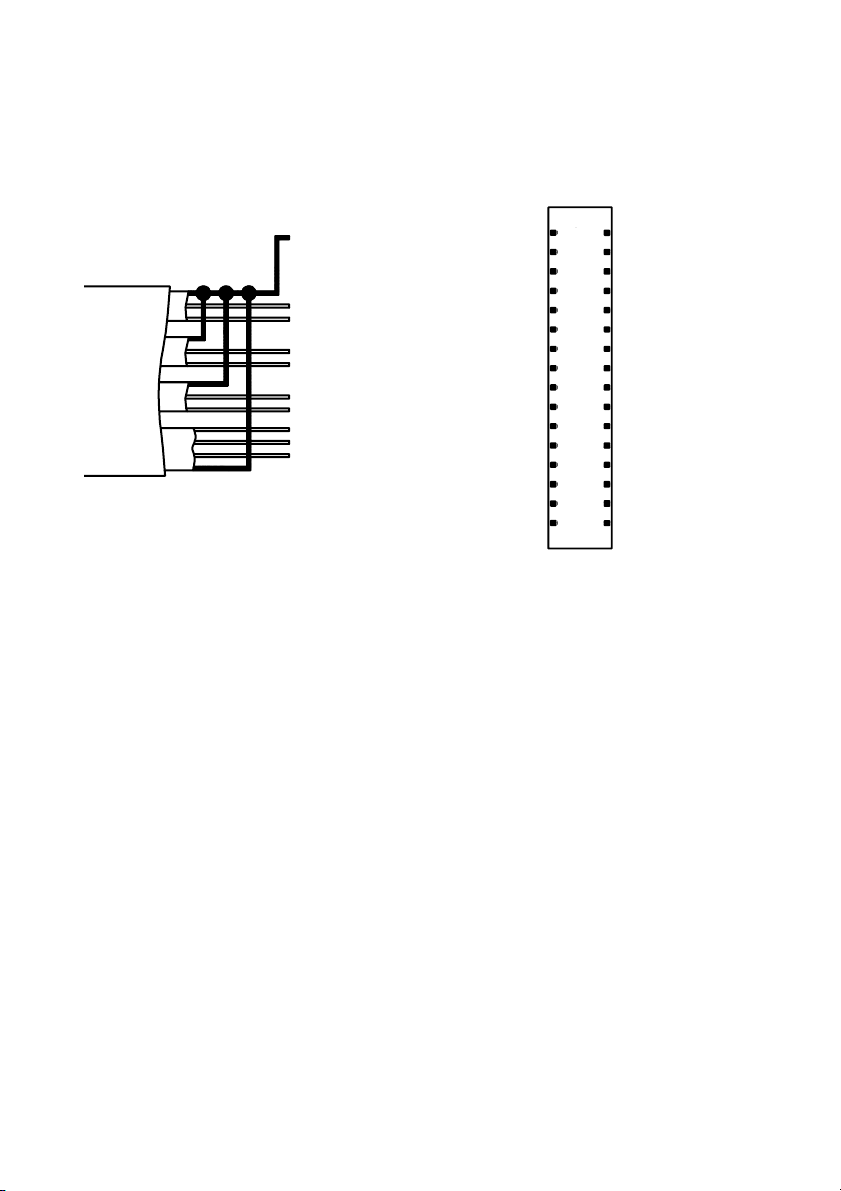
1. Identify the components shown in Figure 5.
Figure 5. Sensor cable to Model 3500
9-wire cable from sensor
Keyed sensor wiring connector
Model 3500
(see Figure 3, page 6)
black (drain wires
from all wire sets)
brown
red
green
white
blue
gray
orange
yellow
violet
yellow
violet
green
blue
brown
c
2
a
c
4
a
6
8
10
12
14
16
18
20
22
24
26
28
30
32
black (drains)
a
orange
a
white
a
gray
a
red
a
a
a
a
a
a
a
a
a
a
c
c
c
c
c
c
c
c
c
c
c
c
c
c
2. Prepare the cable according to the instructions in Micro Motion’s
9-Wire Flowmeter Cable Preparation and Installation Guide.
3. Ensure that the cable has 360° shielding, continuous from the
transmitter to the sensor’s junction box. Two methods can be used:
• Metallic conduit
• Shielded or armored cable
Refer to Micro Motion’s 9-Wire Flowmeter Cable Preparation and
Installation Guide for specific instructions.
4. At the sensor:
a. Clip the cable drain wires.
b. Connect wiring inside the junction box housing and tighten the
screws to hold the wires in place.
For information on your sensor’s junction box terminals, see the
sensor installation manual or Micro Motion’s 9-Wire Flowmeter
Cable Preparation and Installation Guide.
8
Page 10

5. At the transmitter:
a. Connect the color-coded wires to the appropriate terminals. To
identify the terminals, refer to Figure 5, page 8. No bare wires
should remain exposed.
b. If using shielded or armored cable, connect the cable braid to the
rear stud, as described in Micro Motion’s 9-Wire Flowmeter
Cable Preparation and Installation Guide.
STEP 6. Connecting power supply wiring
CAUTION
Improper wiring installation can cause device failure
or measurement error.
• To avoid device failure or measurement error, do not
install power supply wiring in the same cable tray or
conduit as input/output wiring.
• Shut off power supply before installing the applications
platform.
• Make sure power supply voltage matches voltage that
is indicated on power supply wiring terminals. See
Figure 6, page 10.
Referring to Figure 6, page 10, connect the Model 3300/3500 to a power
supply as follows:
2
1. Use 18 to 14 AWG (0,75 to 2,5 mm
) wire.
2. Ground the power supply wiring:
• Connect the ground wire to the middle terminal.
• Connect the power supply ground directly to earth ground.
• Keep all ground leads as short as possible.
• Ensure that all ground wiring has less than 1 ohm impedance.
3. Connect wires to the upper and lower terminals.
A user-supplied switch may be installed in the power supply line. For
compliance with low-voltage directive 73/23/EEC (European
installations), a switch in close proximity to the rack is required.
9
Page 11

Figure 6. Power supply wiring terminals
Power supply wiring
terminals
Terminal designations for
DC power
Terminal designations for
AC power
10
Page 12

©2003, Micro Motion, Inc. All rights reserved. P/N 3300995, Rev. C
*3300995*
Visit us on the Internet at www.micromotion.com
Micro Motion Inc. USA
Worldwide Headquarters
7070 Winchester Circle
Boulder, Colorado 80301
T (303) 530-8400
(800) 522-6277
F (303) 530-8459
Micro Motion Europe
Emerson Process Management
Wiltonstraat 30
3905 KW Veenendaal
The Netherlands
T +31 (0) 318 495 670
F +31 (0) 318 495 689
Micro Motion United Kingdom
Emerson Process Management Limited
Horsfield Way
Bredbury Industrial Estate
Stockport SK6 2SU U.K.
T 0800 966 180
F 0800 966 181
Micro Motion
TM
Micro Motion Asia
Emerson Process Management
1 Pandan Crescent
Singapore 128461
Republic of Singapore
T (65) 6777-8211
F (65) 6770-8003
Micro Motion Japan
Emerson Process Management
Shinagawa NF Bldg. 5F
1-2-5, Higashi Shinagawa
Shinagawa-ku
Tokyo 140-0002 Japan
T (81) 3 5769-6803
F (81) 3 5769-6843
 Loading...