

Page 1
M
Safety Instructions Booklet
IP242/SI
December 2005
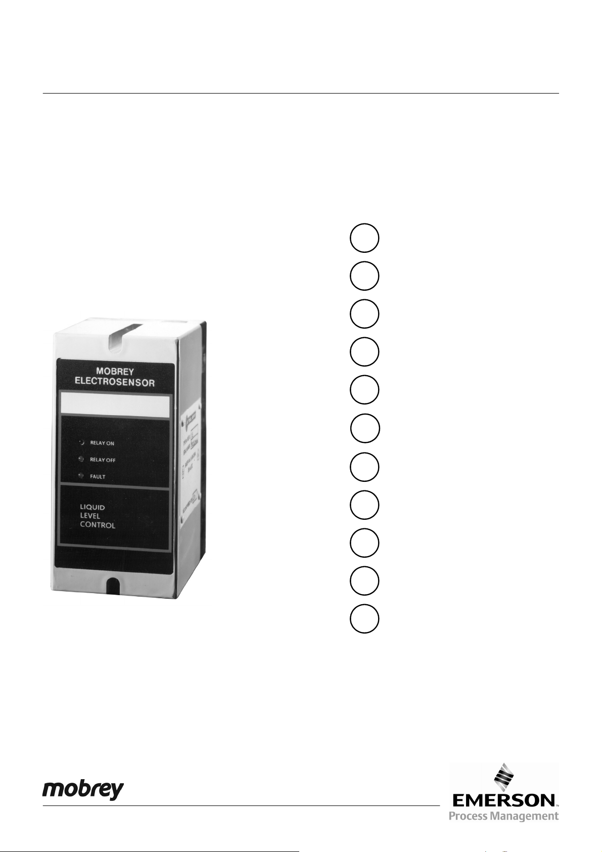
Electrosensor Control Unit
ATEX Safety Instructions
For the
Electrosensor
Control Unit
Model Covered:
ES3L/****
F
Consignes de sécurité (ATEX)
D
Sicherheitshinweis (ATEX)
Säkerhetsinformation (ATEX)
S
E
Información seguridad (ATEX)
NL
IT
FIN
GR
DK
PL
PT
Veiligheidsinformatie (ATEX)
Informazioni per la Sicurezza
(ATEX)
Turvallisuusohjeet (ATEX)
Πληροφορίες ασφαλείας (ATEX)
Sikkerheds information (ATEX)
Instrukcja bezpieczeństwa (ATEX)
Informação de segurança (ATEX)
www.mobrey.com
Page 2
GB
Model numbers covered: MES3L/**** ('*' indicates options in construction, function and materials.)
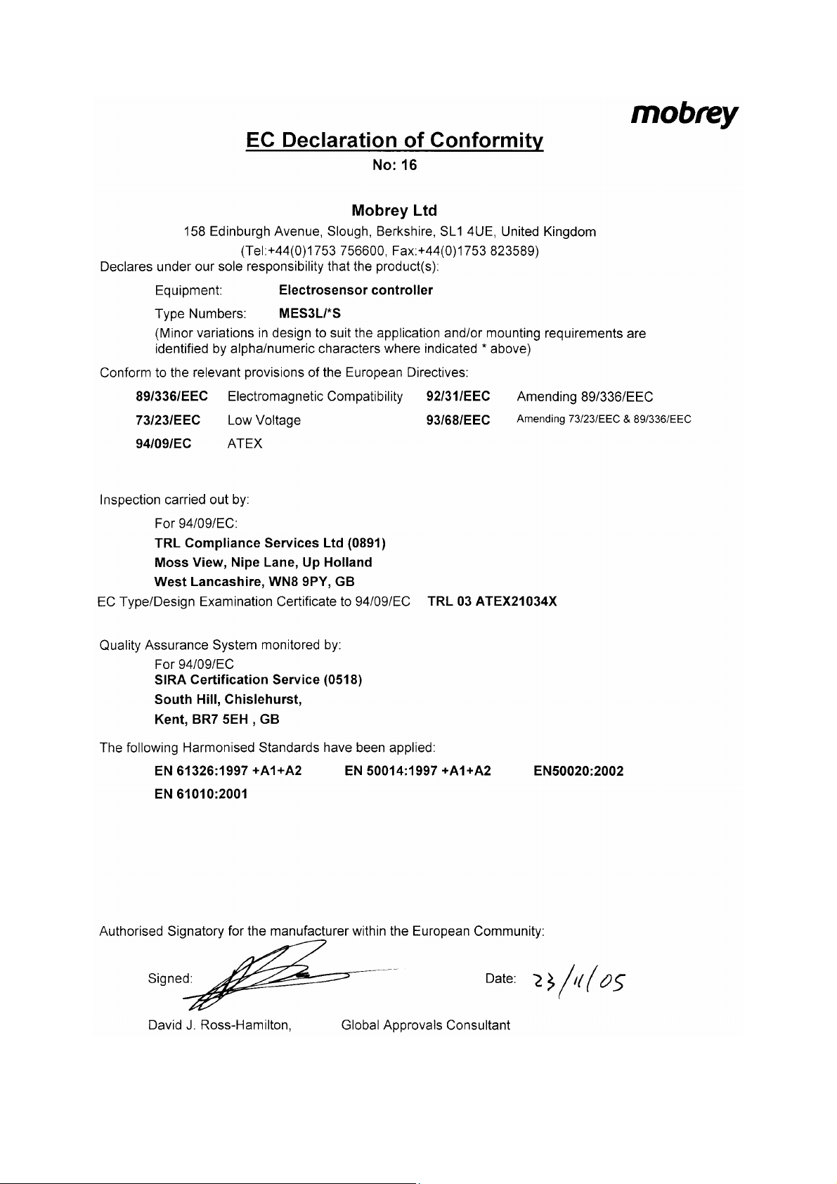
The following instructions apply to equipment covered by certificate number TRL 03ATEX21034X:
1. The MES3L control unit may be connected to a transmitter located in a hazardous area. The MES3L control unit
2. Installation of this equipment shall be carried out by suitably trained personnel, in accordance with the applicable
3. The user should not repair this equipment.
4. If the equipment is likely to come into contact with aggressive substances, it is the responsibility of the user to
5. Wiring instructions:
6. Technical data:
Instructions specific to hazardous area installations
must not itself be located in a hazardous area.
code of practice.
take suitable precautions that prevent it from being adversely affected, thus ensuring that the type of protection is
not compromised.
Aggressive Substances
Suitable Precautions
(a) The MES3L must not be connected to a supply exceeding 250V r.m.s. or dc, or to apparatus containing a
source of voltage exceeding 250V r.m.s. or dc.
(b) The Intrinsically Safe outputs of the MES3L Control Unit may be connected to certified equipment used in a
hazardous area requiring category 1 equipment, with flammable gases and vapours with apparatus groups
IIC, IIB and IIA. No additional I.S. barrier is required.
(c) The fuse must only be replaced with the type specified.
(d) The intrinsic safe outputs must not be connected together.
(a) Materials of construction: Refer to Part numbering identification chart.
(b) Coding: II (1) G
[EEx ia] IIC
(c) Electrical:
Output Parameters: Terminal numbers 1 & 2: Uo: 20.5V, Io: 181mA, Po: 0.92W, Ci: 0µF, Li: 0 mH.
Cabling: The Capacitance and Inductance of the load connected must not exceed the following values:
– e.g. acidic liquids or gases that may attack metals or solvents that may affect
polymeric materials.
– e.g. regular checks as part of routine inspections or establishing from the
material’s data sheet that it is resistant to specific chemicals.
Terminal numbers 3 & 4: Uo: 20.5V, Io: 181mA, Po: 0.92W, Ci: 0µF, Li: 0 mH.
Terminal numbers 14, 15 & 16: Um: 250 Vrms.
Relay Contact ratings: U<250Vrms, I<5A, P<100VA
Group Capacitance Inductance or L/R ratio
µF mH µH/ohm
IIC 0.203 1.08 38.5
IIB 1.33 4.34 154.1
IIA 5.12 8.68 308.3
7. Special conditions for safe use:
(a) The load/cable parameters shown above must be complied with.
(b) The control unit must be installed in a clean, dry and well controlled environment.
Please note that the safety instructions and certificates in this publication have been translated from English (United Kingdom).
Page 2
IP242/SI
Page 3
3
IP242/SI
Page
Page 4

F
Instructions spécifiques concernant l'installation en atmosphères explosibles
Modèles concernés: MES3L/**** ('*' indique une option de construction ou de fonction.)
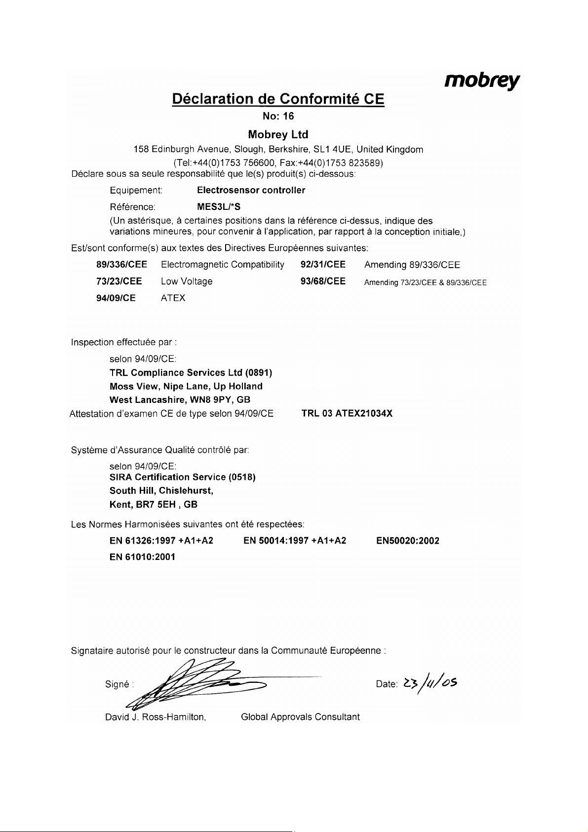
Les instructions suivantes sont applicables à l'instrumentation spécifiée dans le certificat TRL 03ATEX21034X:
1. L'unité de contrôle MES3L peut être reliée à un transmetteur qui est situé en zone dangereuse. Par contre,
2. L'installation de l'appareil sera effectué par du personnel compétent en conformité avec les normes locales
3. L'utilisateur ne doit pas réparer l'appareil.
4. Si l'appareil risque d'être en contact avec des substances agressives ou corrosives, il y ait de la responsabilité
5. Instructions de câblage:
6. Données Techniques:
l'unité de contrôle MES3L ne peut pas être montée en zone dangereuse
d'installation.
de l'utilisateur de prendre des précautions nécessaires pour éviter toute détérioration de l'appareil afin que sa
classe de protection ne soit pas compromise.
Substances aggressives
Précautions nécessaires
(a) L'unité de contrôle MES3L ne doit pas être reliée à une alimentation supérieure à 250 V CA efficace ou CC,
ni à un appareil comportant une alimentation supérieure à 250 V CA efficace ou CC.
(b) Les sorties de sécurité intrinsèque de l'unité de contrôle MES3L peuvent être reliées à des appareils
agréés pour une utilisation en zone dangereuse nécessitant du matériel de catégorie 1, avec des gaz et
des vapeurs inflammables selon les groupes IIC, IIB et IIA. Aucune barrière supplémentaire de sécurité
intrinsèque n'est nécessaire.
(c) Le fusible doit être remplacé par le type spécifié.
(d) Les sorties de sécurité intrinsèques ne doivent pas être connectées ensemble.
(a) Matière de construction: Se référer au tableau "Références pour commander".
(b) Code: II (1) G
[EEx ia] IIC
(c) Electrique:
Paramètres de sortie: Numéros de terminaux 1 & 2: Uo: 20.5V, Io: 181mA, Po: 0.92W, Ci: 0µF, Li: 0 mH.
Câblage: La capacité et l'inductance de la charge reliée ne doivent pas dépasser les valeurs suivantes:
– ex. Liquides ou gaz acides qui peuvent attaquer des métaux, ou des solvants
qui peuvent attaquer des matériaux à base de polymères.
– ex. contrôles réguliers d'état lors des inspections de maintenance ou s'assurer
de la compatibilité des matières de construction du capteur avec la présence de
tous les produits chimiques spécifiques à l'application.
Numéros de terminaux 3 & 4: Uo: 20.5V, Io: 181mA, Po: 0.92W, Ci: 0µF, Li: 0 mH.
Numéros de terminaux 14, 15 & 16: Um: 250 Vrms.
Pouvoir de coupure du relais: U<250Vrms, I<5A, P<100VA
Groupe Capacitance Inductance ou Rapport L/R
µF mH µH/ohm
IIC 0.203 1.08 38.5
IIB 1.33 4.34 154.1
IIA 5.12 8.68 308.3
7. Recommandations pour une utilisation en toute sécurité:
(a) L'unité de contrôle doit être installée dans un environnement propre, sec et contrôlé.
(b) Les paramètres électriques ci-dessus doivent être respectés.
Remarque: les consignes de sécurité et les certificats figurant dans cette publication sont traduits de l'anglais (Royaume-Uni).
Page 4
IP242/SI
Page 5
5
IP242/SI
Page
Page 6
D
Anleitung zur Installation in gefährlicher Umgebung
Modell-Nr.: MES3L/**** ('*' bedeutet Option für Konstruktion, Funktion und Material.)
Die folgende Anleitung wird verwendet für Geräte mit der Bescheinigung-Nr. TRL 03ATEX21034X:
1. Das Steuergerät MES3L wird an einen Transmitter, der im Ex-Bereich montiert ist, angeschlossen. Das
2. Die Installaton der Geräte sollte gemäß den gültigen technischen Regeln durch geschultes.
3. Das Gerät sollte nicht vom Kunden repariert werden.
4. Wenn die Wahrscheinlichkeit besteht, daß die Geräte in Kontakt mit aggressiven Substanzen kommen, so liegt
5. Elektrische Anschlüsse:
6. Technische Daten:
Steuergerät MES3L wird ausserhalb des Ex-Bereiches installiert.
es in der Verantwortlichkeit des Kunden, nachteilige Beeinträchtigung zu verhindern.
Aggressive Substanzen – z.B. saure Flüssigkeiten oder Gase, können Metalle angreifen. Lösungsmittel
können Kunststoffe beeinträchtigen.
Vorsichtsmassnahmen
(a) Das Steuergerät MES3L darf nicht an Versorgungsspannungen über 250 VSS oder DC oder an Geräten,
die eine interne Spannung von über 250 VSS oder DC führen, angeschlossen werden.
(b) Die eigensicheren Ausgänge des MES3L Steuergerätes werden an zertifizierte Geräte, die in Ex Zone 1
der Gasgruppen IIC, IIB und IIA. Zusätzliche Zenerbarrieren werden nicht benötigt.
(c) Die Sicherung darf nur durch eine des gleichen, spezifizierten Typs ausgetauscht werden.
(d) Die Eigensicherheitsausgänge dürfen nicht verbunden werden.
(a) Konstruktionsmaterialien: siehe Modell-Nr. im Datenblatt.
(b) Kodierung: II (1) G
(c) Elektrisch:
Ausgangsparameter: Anschlusskennziffern 1 & 2: Uo: 20.5V, Io: 181mA, Po: 0.92W, Ci: 0µF, Li: 0 mH.
Verkabelung: Die Kapazitanz und Induktion der angeschlossenen Last darf die folgenden Werte nicht
– z.B. regelmässige Kontrollen als Teil von Routineuntersuchunge oder mit
Materiallisten nachweisen, das das Material beständiggegen spezifische
Chemiekalien ist.
[EEx ia] IIC
Anschlusskennziffern 3 & 4: Uo: 20.5V, Io: 181mA, Po: 0.92W, Ci: 0µF, Li: 0 mH.
Anschlusskennziffern 14, 15 & 16: Um: 250 Vrms.
Relais-Kontakt-Bewertungen: U<250Vrms, I<5A, P<100VA
überschreiten:
Gruppe Kapazität Induktivität oder L/R Verhältnis
µF mH µH/ohm
IIC 0.203 1.08 38.5
IIB 1.33 4.34 154.1
IIA 5.12 8.68 308.3
7. Spezielle Vorgaben zum sicheren Gebrauch:
(a) Die oben aufgeführten Bedingungen für Kabeltyp und Last/Bürde müssen in jedem Fall eingehalten werden.
(b) Die Steuereinheit muss in sauberer, trockener und gut überwachter Umgebung eingesetzt werden.
Hinweis: alle Sicherheitshinweise und Bescheinigungen in dieser Anleitung sind aus dem Englischen übersetzt.
Page 6
IP242/SI
Page 7
7
IP242/SI
Page
Page 8
S
Bruksanvisning för MES3L gällande installation i explosionsfarligt område
Omfattade typnummer: MES3L/**** ('*' avser varianter vad gäller konstruktion, funktion och material.)
Följande instruktioner gäller för MES3L med certifikat nummer TRL 03ATEX21034X:
1. Styrenheten MES3L kan anslutas till en givare som sitter i explosionsfarlig zon. Styrenheten får inte själv
2. Installation skall företagas av lämpligt utbildad personal i enlighet med god installationssed och gällande lokala
3. Apparaten är inte avsedd att repareras av användaren om fel uppstår.
4. Om det är troligt att MES3L kommer i kontakt med aggressiva substanser så åligger det användaren att vidtaga
5. Inkopplingsanvisningar:
6. Tekniska data:
placeras i Ex-zon.
bestämmelser.
lämpliga åtgärder för att förhindra att apparaten blir negativt påverkad så att det inbyggda explosionsskyddet helt
eller delvis sätts ur funktion.
Aggressiva substanser
Försiktighetsåtgärder
(a) Styrenheten MES3L får ej anslutas till en spänningsmatning som överskrider 250V r.m.s. eller dc, eller till
apparatur som innehåller en spänningskälla som överskrider 250V r.m.s. eller dc.
(b) De egensäkra utgångarna från MES3L får anslutas till godkänd utrustning som används i explosionsfarlig miljö
som kräver utrustning enligt kategori 1, med brännbara gaser och ångor med apparatgrupper IIC, IIB och IIA.
Ingen ytterligare zenerbarriär behövs.
(c) Säkringen får endast ersättas med den specificerade typen.
(d) De intrinsiska säkra uteffekterna får inte sammankopplas.
(a) Material: Se identifieringstabell med typnummer som anger använda material.
(b) Ex-kod: II (1) G
(c) Elektrisk:
Utgångsparametrar: Kabelfästenr 1 & 2: Uo: 20.5V, Io: 181mA, Po: 0.92W, Ci: 0µF, Li: 0 mH.
Kabeldragning: Kapacitansen och induktansen hos den anslutna belastningen får inte överstiga följande
– T.ex. sura vätskor eller gaser som kan angripa metall, eller lösningsmedel som
kan angripa polymerer.
– T.ex. regelbunden inspektion som en del av underhållsrutinen eller kontroll
genom materialdatablad eller korrosionstabeller att materialet i MES3L står emot
specifika kemikalier.
[EEx ia] IIC
Kabelfästenr 3 & 4: Uo: 20.5V, Io: 181mA, Po: 0.92W, Ci: 0µF, Li: 0 mH.
Kabelfästenr 14, 15 & 16: Um: 250 Vrms.
Reläkontaktdata: U<250Vrms, I<5A, P<100VA
värden:
Grupp Kapacitans Induktans eller L/R Ratio
µF mH µH/ohm
IIC 0.203 1.08 38.5
IIB 1.33 4.34 154.1
IIA 5.12 8.68 308.3
7. Monteringsanvisning:
(a) Kabeldata enligt ovan måste innehållas.
(b) Kontrollenheten måste installeras i ren, torr och välkontrollerad miljö.
Observera att säkerhetsföreskrifter och intyg i denna handbok är översatta från engelska (Storbritannien).
Page 8
IP242/SI
Page 9
9
IP242/SI
Page
Page 10

E
Instrucciones específicas para instalación en zonas peligrosas
MES3L no debe estar en zona peligrosa.
aplicables en la práctica.
precauciones necesarias para prevenir que el equipo se vea afectado, y debe asegurarse que el tipo de
protección no quede dañada.
Sustancias agresivas – p.ej. líquidos o gases ácidos que pueden atacar metales, o disolventes que
Precauciones aconsejables
(a) La MES3L no debe conectarse a una tensión superior a 250V c.a. ó a equipos con una fuente de
alimentación que pueda superar los 250V.
(b) Las salidas intrinsecamente seguras de la unidad de control MES3L deben conectarse a los equipos
certificados e instalados en la zona peligrosa que requieran equipos de categoría 1, para gases y vapores
grupos IIC, IIB y IIA. No hacen falta barreras de s.i. adicionales.
(c) El fusible debe sustituirse por el tipo especificado.
(d) Las corrientes intrínsecas seguras no se conectan entre si.
(a) Materiales: Hacer referencia a la tabla de identificación de las partes.
(b) Código: II (1) G
(c) Eléctricos:
Parámetros de salida: Números de terminal 1 & 2: Uo: 20.5V, Io: 181mA, Po: 0.92W, Ci: 0µF, Li: 0 mH.
Cableado: La capacidad e inductancia de la carga conectada no debe exceder los siguientes valores:
[EEx ia] IIC
pueden afectar materiales poliméricos.
– p.ej. comprobaciones regulares como parte de inspecciones rutinarias ó
aplicando materiales que resistan a los agentes químicos.
Números de terminal 3 & 4: Uo: 20.5V, Io: 181mA, Po: 0.92W, Ci: 0µF, Li: 0 mH.
Números de terminal 14, 15 & 16: Um: 250 Vrms.
Valor de los contactos de relé: U<250Vrms, I<5A, P<100VA
Modelos número cubiertos por el certificado: MES3L/**** ('*' indica variantes de fabricación, funcionamiento y materiales.)
Estas instrucciones se aplican para los equipos provistos de certificado número TRL 03ATEX21034X:
1. La unidad de control MES3L debe conectarse al transmisor instalado en zona peligrosa. La unidad de control
2. La instalación de este equipo debe hacerse por personal entrenado convenientemente, y según los códigos
3. Este equipo no puede ser reparado por el usuario.
4. Si el equipo está en contacto con sustancias agresivas, es responsabilidad del usuario el tomar las
5. Instrucciones de conexionado:
6. Datos Técnicos:
Grupo Capacitancia Inductancia ó L/R Relación
µF mH µH/ohm
IIC 0.203 1.08 38.5
IIB 1.33 4.34 154.1
IIA 5.12 8.68 308.3
7. Condiciones especiales para uso seguro:
(a) Los parámetros carga/cable mostrados arriba deben estar de acuerdo con.
(b) La unidad de control debe ser instalada en un ambiente limpio, seco y bien controlado.
Por favor tenga en cuenta que las instrucciones de seguridad y certificados en esta publicación han sido traducidos del inglés (Reino Unido).
Page 10
IP242/SI
Page 11

IP242/SI
Page 11
Page 12

NL
Modelnummers vallend onder: MES3L/**** ('*' geeft de verschillen/mogelijkheden in constructie, functie en materiaal aan.)
De volgende instructies gelden voor de MES3L behorende bij certificaatnummer TRL 03ATEX21034X:
1. De MES3L controle unit kan aangesloten worden op een transmitter in een gevaarlijke omgeving. De MES3L
2. Deze apparatuur dient te worden geïnstalleerd door goed opgeleid personeel, in overeenstemming met de
3. Deze apparatuur is niet geschikt voor reparatie door de eindgebruiker.
4. Wanneer de mogelijkheid bestaat dat de apparatuur met agressieve stoffen in aanraking komt, is de gebruiker
5. Bekabeling instructies:
6. Technische gegevens:
Specifieke instructies voor installaties in gevaarlijke omgevingen
controle unit mag zelf absoluut niet in een gevaarlijke omgeving geplaatst worden.
reglementen die van toepassing zijn.
verantwoordelijk voor het treffen van passende voorzorgsmaatregelen, om te voorkomen dat het apparaat en de
getroffen beschermingsmaatregelen nadelig worden beïnvloed.
Agressieve stoffen – bijv. zure vloeistoffen of gassen die metaal kunnen aantasten, of oplossingen die
polymere materialen kunnen aantasten.
Passende voorzorgsmaatregelen
(a) The MES3L mag niet aangesloten worden op een voeding die de 250V r.m.s. of dc overschrijdt of
apparaten die een voedingsbron bevatten die de 250 V r.m.s of dc overschrijden.
(b) De Intrinsiek Veilige output van de MES3L controle units kunnen aangesloten worden op goedgekeurde
apparaten die gebruikt worden in een gevaarlijke omgeving waar categorie 1 apparaten noodzakelijk zijn. Bij
ontbrandbare gassen en dampen met klasse IIC, IIB en IIA. Er is geen extra I.S. barrier nodig.
(c) De zekering mag alleen vervangen worden door de aangegeven types.
(d) De intrinsieke veilige outputs mogen niet aan elkaar verbonden worden.
(a) Materiaal: Zie onderdeel nummer identificatie kaart.
(b) Codering: II (1) G
[EEx ia] IIC
(c) Electrisch:
Outputparameters: Nummers aansluitpunten 1 & 2: Uo: 20.5V, Io: 181mA, Po: 0.92W, Ci: 0µF, Li: 0 mH.
Bekabeling: De capacitantie en inductantie van de verbonden belasting mogen de volgende waarden niet
overschrijden:
– bijv. regelmatig uitgevoerde controles in het kader van routine-inspecties,
of nagaan of in de materiaalspecificaties wordt aangegeven dat het
materiaal bestand is tegen bepaalde chemicaliën.
Nummers aansluitpunten 3 & 4: Uo: 20.5V, Io: 181mA, Po: 0.92W, Ci: 0µF, Li: 0 mH.
Nummers aansluitpunten 14, 15 & 16: Um: 250 Vrms.
Relais contact gegevens: U<250Vrms, I<5A, P<100VA
Groep Capaciteit Zelfinductie of L/R Verhoudingsgetal
µF mH µH/ohm
IIC 0.203 1.08 38.5
IIB 1.33 4.34 154.1
IIA 5.12 8.68 308.3
7. Bijzondere voorwaarden voor veilig gebruik:
(a) Er moet voldaan worden aan de hierboven vermelde belasting/ kabel parameters.
(b) De controle unit moet geinstalleerd worden in een schone, droge en goed geregelde omgeving.
Gelieve er rekening mee te houden dat de veiligheidsinstructies en certificaten in deze publicatie uit het Engels (Verenigd Koninkrijk)
vertaald zijn.
Page 12
IP242/SI
Page 13

3
IP242/SI
Page 1
Page 14

IT
Istruzioni Specifiche per le installazioni in area pericolosa
controllo MES3L deve essere installata in area sicura.
adeguatamente preparato.
responsabilità dell’utilizzatore prendere le necessarie precauzioni per prevenire eventuali danni e assicurare che
il grado di protezione non venga compromesso.
Sostanze aggressive
Precauzioni applicabili
(a) MES3L non deve essere collegata ad una alimentazione che superi il valore di 250 V r.m.s. o c.c., o ad una
apparecchiatura che contenga una sorgente di alimentazione che superi i 250V r.m.s. or c.c.
(b) L’uscita a Sicurezza Intrinseca dell’unità di controllo MES3L può essere collegata ad uno strumento
certificato per l’uso in area pericolosa che richieda Categoria 1, con gas o vapori infiammabili dei Gruppi
IIC, IIB e IIA. Non è richiesto l’uso di una addizionale barriera a Sicurezza Intrinseca.
(c) Il fusibile, nel caso in cui sia necessario, deve essere sostituito con uno dello stesso tipo e caratteristiche.
(d) Le uscite di sicurezza che ne fanno parte non devono essere connesse tra loro.
(a) Materiali: riferirsi alla descrizione per la composizione del codice modello.
(b) Codifica: II (1) G
(c) Elettrico:
Parametri di produzione: Numeri del Terminale 1 & 2: Uo: 20.5V, Io: 181mA, Po: 0.92W, Ci: 0µF, Li: 0 mH.
Cavi: La Capacità e l'Induttanza del carico connesso non devono superare i seguenti valori:
– es. Acidi, liquidi o gassosi, che possono attaccare I metalli, o solventi che
potrebbero intaccare i materiali polimerici.
– es. Controllare le apparecchiature con una scadenza regolare e pianificata, oppure
assicurarsi che I materiali, con cui è costruita l’apparecchiatura, siano
specificatamente compatibili con le sostanze chimiche presenti.
[EEx ia] IIC
Numeri del Terminale 3 & 4: Uo: 20.5V, Io: 181mA, Po: 0.92W, Ci: 0µF, Li: 0 mH.
Numeri del Terminale 14, 15 & 16: Um: 250 Vrms.
Portata contatti relè: U<250Vrms, I<5A, P<100VA
Numeri di Modello applicabili: MES3L/**** ('*' identifica diverse opzioni relative alla costruzione, alla funzione ed ai materiali.)
Le istruzioni che seguono sono applicabili alle apparecchiature che posseggono la certificazione numero
TRL 03ATEX21034X:
1. L’unità di controllo MES3L può essere collegata ad un trasmettitore installato in area pericoloso. L’unità di
2. L’installazione di questa apparecchiatura deve essere eseguita secondo le normative applicabili e da personale
3. Questa apparecchiatura non può essere riparata dall'utilizzatore.
4. Se sussiste la possibilità che l’apparecchiatura possa venire a contatto con sostanza aggressive, è
5. Istruzioni per il cablaggio:
6. Dati Tecnici:
Groppo Capacita Induttanza o Rapporto L/R
µF mH µH/ohm
IIC 0.203 1.08 38.5
IIB 1.33 4.34 154.1
IIA 5.12 8.68 308.3
7. Circostanze speciali per usare in un senso sicuro:
(a) I parametri del carico/cavo, sopra indicati, devono essere rispettati.
(b) L'unità di controllo deve essere installata in un ambiente pulito, secco e ben controllato.
Notare che le istruzioni di sicurezza e i certificati riportati in questo documento sono stati tradotti dall'inglese britannico.
Page 14
IP242/SI
Page 15

5
IP242/SI
Page 1
Page 16

FIN
Sisältää seuraavat mallinumerot: MES3L/**** ('*' tarkoittaa rakennus-, toiminta- ja materiaalivaihtoehtoja.)
Seuraavat ohjeet koskevat MES3L-nestetasokytkintä, jolla on sertifikaattinumero TRL 03ATEX21034X:
1. MES3L-ohjausyksikön voi kytkeä vaarallisella alueella sijaitsevaan lähettimeen. MES3L-ohjausyksikkö itse ei
2. Tämän laitteen saa asentaa vain asianmukaisesti koulutettu henkilöstö soveltuvien menettelysääntöjen
3. Lisäksi MES3L tulee ainoastaan puhdistaa märällä rätillä.
4. Jos on todennäköistä, että laite tulee kosketuksiin aggressiivisten aineiden kanssa, käyttäjällä on vastuu ryhtyä
5. Kytkentäohjeet:
6. Tekniset tiedot:
Erityisohjeet asennuksiin vaarallisilla alueilla
saa sijaita vaarallisella alueella.
mukaisesti.
sopiviin varotoimiin, jotka estävät laitetta vahingoittavat vaikutukset ja varmistavat, että sen suojauskyky ei
heikkene.
Aggressiiviset aineet
Sopivat varotoimet
(a) MES3L:ta ei saa kytkeä virtalähteeseen, joka ylittää 250 V (rms tai tasavirta), eikä laitteeseen, johon
sisältyy 250V (rms tai tasavirta) ylittävä jännitelähde..
(b) MES3L-ohjausyksikön räjähdysturvalliset ulostulot voi kytkeä sertifioituihin laitteisiin, joita käytetään luokan
1 laitteita vaativilla vaarallisilla alueilla, tulenarkojen kaasujen ja höyryjen vaatiessa laiteryhmiä IIC, IIB ja
IIA. Muuta räjähdysturvasuojaa ei lisäksi tarvita.
(c) Sulakkeen saa vaihtaa ainoastaan määritettyyn tyyppiin.
(d) Sisäisiä turvallisuustehoja ei tule laittaa yhteen.
(a) Materiaalit: Katso numerontunnistuslistaa.
(b) Koodit: II (1) G
(c) Sähköinen:
Tulostusarvot: Terminaalinumerot 1 & 2: Uo: 20.5V, Io: 181mA, Po: 0.92W, Ci: 0µF, Li: 0 mH.
Kaapelointi: Lastin kapasiteetti ja induktanssin ei tule ylittää seuraavia arvoja:
– esim. happonesteet tai -kaasut, jotka voivat syövyttää metalleja, tai liuotteet,
jotka voivat vaikuttaa polymeerimateriaaleihin.
– esim. säännölliset rutiinitarkastukset tai sen toteaminen MDS-materiaalitiedoista,
että laite kestää tiettyjä kemikaaleja.
[EEx ia] IIC
Terminaalinumerot 3 & 4: Uo: 20.5V, Io: 181mA, Po: 0.92W, Ci: 0µF, Li: 0 mH.
Terminaalinumerot 14, 15 & 16: Um: 250 Vrms.
Releen kontaktiarvot: U<250Vrms, I<5A, P<100VA
Ryhmä kapasitanssi Induktanssi tai L/R-suhde
µF mH µH/ohm
IIC 0.203 1.08 38.5
IIB 1.33 4.34 154.1
IIA 5.12 8.68 308.3
7. Turvallisen käytön erikoisehdot:
(a) Ylläolevia kuorma-/kaapeliparametreja tulee noudattaa.
(b) Kontrolliyksikkö tulee asentaa puhtaaseen, kuivaan ja hyvin valvottuun ympäristöön.
Huomaa, että tämän julkaisun turvaohjeet ja todistukset on käännetty (Iso-Britannian) englannista.
Page 16
IP242/SI
Page 17

7
IP242/SI
Page 1
Page 18

GR
Ισχυει για µοντελλα:: MES3L/**** ('*' υποδεικνυει επιλογες στην οικοδοµηση λειτουργια και υλικα.)
Οι ακολουθες οδηγιες ισχυουν για συσκευες µε τον αριθµο πιστοποιητικου TRL 03ATEX21034X:
1. H µονάδα ελέγχου MES3L µπορεί να συνδεθεί µε ένα ποµπό τοποθετηµένο σε µια επικίνδυνη ζώνη. Η µονάδα
2. Η
3. Επιπροσθετως το MES3L πρεπει να καθαριζεται µε υγρο πανι.
4. Αν υπάρχει πιθανότητα ο εξοπλισµός να έλθει σε επαφή µε επικίνδυνες ουσίες, τότε ο χρήστης έχει την
5. Οδηγίες τοποθέτησης ηλεκτρικών καλωδίων:
6. Τεχνικα στοιχεια:
Ειδικες οδηγιες για εγκαταστασεις σε επικινδυνες περιοχες
ελέγχου MES3L δεν πρέπει η ίδια να τοποθετείται σε επικίνδυνη περιοχή.
εγκατάσταση αυτού του εξοπλισµού θα πρέπει να διεξάγεται από κατάλληλα εκπαιδευµένο προσωπικό,
σύµφωνα µε τον ισχύοντα κώδικα πρακτικής.
ευθύνη
να λάβει τις κατάλληλες προφυλάξεις, ώστε να εµποδίσει τον εξοπλισµό από το να επηρεαστεί δυσµενώς,
εξασφαλίζοντας έτσι ώστε ότι το είδος προφύλαξης να µη συµβιβάζεται.
Επιθετικές ουσίες
Κατάλληλες προφυλάξεις
(a) Η MES3L δεν πρέπει να συνδεθεί µε µια παροχή ρεύµατος, που υπερβαίνει τα 250 βόλτ r.m.s. ή dc., ή µε
µια συσκευή περιέχουσα µια πηγή παροχής τάσης ρεύµατος που υπερβαίνει τα 250 βολτ r.m.s. ή dc.
(b) Οι Ουσιαστικά Ασφαλείς έξοδοι της Μονάδας Ελέγχου MES3L µπορεί να συνδεθούν µε πιστοποιηµένο
εξοπλισµό, ο οποίος χρησιµοποιείται σε επικίνδυνη περιοχή που απαιτεί εξοπλισµό της κατηγορίας 1, µε
εύφλεκτα αέρια και ατµούς µε συσκευή των οµάδων IIC, IIB και IIA. ∆ε χρειάζεται επιπρόσθετο I.S. φράγµα.
(c) Η ασφάλεια πρέπει να αντικατασταθεί µόνο από τον προσδιορισµένο τύπο.
(d) Οι ουσιαστικά ασφαλείς έξοδοι δεν πρέπει να συνδέονται.
(a) Υλικα: Βλεπε λιστα κωδικων των εξαρτηµατων.
(b) Κωδικός: II (1) G
(c) Ηλεκτρικός
Παράµετροι εξόδου: Τελικές Μετρήσεις 1 & 2: Uo: 20.5V, Io: 181mA, Po: 0.92W, Ci: 0µF, Li: 0 mH.
Καλωδίωση: Η Ευρυχωρία και η Επαγωγή του φορτίου που είναι συνδεδεµένα δεν πρέπει να υπερέχει τις
– π.χ. όξινα υγρά ή αέρια που πιθανόν να προσβάλλουν τα µέταλλα, ή διαλυτικά
που πιθανόν να επηρεάσουν τα πολυµερή υλικά.
– π.χ. τακτικοί έλεγχοι σαν µέρος της ρουτίνας επιθεώρησης ή απόδειξη από
φύλλα δεδοµένων του υλικού ότι αντέχει σε ειδικές χηµικές ουσίες.
[EEx ia] IIC
:
Τελικές Μετρήσεις 3 & 4: Uo: 20.5V, Io: 181mA, Po: 0.92W, Ci: 0µF, Li: 0 mH.
Τελικές Μετρήσεις 14, 15 & 16: Um: 250 Vrms.
Επιδόσεις της θέσης του ρελέ: U<250Vrms, I<5A, P<100VA
παρακάτω αξίες:
Κατηγορία Χωρητικότητα Επαγωγιµότητα ή L/R Αναλογία
µF mH µH/ohm
IIC 0.203 1.08 38.5
IIB 1.33 4.34 154.1
IIA 5.12 8.68 308.3
7. Ειδικές συνθήκες για ασφαλή χρήση:
(a) Οι παράµετροι του φορτίου/καλωδίου που παρατίθονται παραπάνω πρέπει να ακολουθούνται.
(b) Η συσκευή ελέγχου πρέπει να εγκατασαθεί σε ένα καθαρό, στεγνό και καλά ελεγχόµενο περιβάλλον.
Παρακαλούµε σηµειώστε πως οι οδηγίες ασφαλείας και τα πιστοποιητικά σ'αυτό το έντυπο έχουν µεταφραστεί από τα Αγγλικά
(Ηνωµένο Βασίλειο).
Page 18
IP242/SI
Page 19

9
IP242/SI
Page 1
Page 20

DK
Gældende for følgende typer: MES3L/**** ('*' angiver optioner i konstruktion, funktion og materialer.)
Følgende instruktioner er gældende for udstyr, der er omfattet af certifikat TRL 03ATEX21034X:
1. MES3L kontrolenhed kan forbindes til en transmitter placeret i risikoområde. Selve MES3L kontrolenheden må
2. Installation skal udføres af trænet personale i henhold til gældende regler og praksis.
3. Dette udstyr er ikke beregnet til at skulle repareres af bruger.
4. Hvis det er sandsynligt, at udstyret kommer i kontakt med aggressive substanser, så er det brugers ansvar at træffe
5. Ledningsinstruktioner:
6. Tekniske data:
Instruktioner for installationer i risikoområder
ikke være placeret i risikoområde.
de fornødne foranstaltninger, således at skader undgås, og det sikres, at beskyttelsen ikke bringes i fare.
Aggressive substanser – så som syreholdige væsker eller gasser, der kan angribe metaller eller
opløsningsmidler, der kan påvirke polymer materialer.
Foranstaltninger
(a) MES3L’en må ikke forbindes til en forsyning, der overstiger 250V r.m.s. eller dc, eller til instrument med
strømenergikilde, der overstiger 250V r.m.s. eller dc.
(b) De galvanisk adskilte udgange på MES3L Kontrolenheden kan forbindes til certificeret udstyr anvendt i
risikoområder, der kræver kategori 1 udstyr, med brandbare gasser og dampe med apparatur gruppe IIC,
IIB og IIA. Ingen yderlig Galvanisk Adskilt barriere påkrævet.
(c) Sikringen må kun erstattes med den specificerede type.
(d) De indre sikkerheds udgangseffekter må ikke forbindes.
(a) Materialer: Se Part nr. for identifikation.
(b) Kode: II (1) G
(c) Elektrisk:
Output parametre: Terminalnumre 1 & 2: Uo: 20.5V, Io: 181mA, Po: 0.92W, Ci: 0µF, Li: 0 mH.
Kabellægning: Kapacitancen og induktiviteten for den tilsluttede belastning bør ikke overskride de
– så som check med passende mellemrum som en del af rutineinspektionen eller
fastslå ved hjælp af materiale datablad, at det er modstandsdygtig over for de
specifikke kemikalier.
[EEx ia] IIC
Terminalnumre 3 & 4: Uo: 20.5V, Io: 181mA, Po: 0.92W, Ci: 0µF, Li: 0 mH.
Terminalnumre 14, 15 & 16: Um: 250 Vrms.
Relækontakt-ydelse: U<250Vrms, I<5A, P<100VA
følgende værdier:
Gruppe Kapacitans Induktivitet eller L/R Proportion
µF mH µH/ohm
IIC 0.203 1.08 38.5
IIB 1.33 4.34 154.1
IIA 5.12 8.68 308.3
7. Specielle betingelser for brug i risikoområde:
(a) Belastnings-/kabelparametrene vist herover skal overholdes.
(b) Kontrolenheden skal installeres i et rent, tørt og godt kontrolleret miljø.
Bemærk venligst at sikkerhedsvejledninger og certifikater i denne publikation er oversat fra engelsk (United Kingdom).
Page 20
IP242/SI
Page 21

IP242/SI
Page 21
Page 22

PL
Symbol przyrządu: MES3L/**** ('*' oznacza wybraną opcję wykonania przyrządu.)
Niniejsze zalecenia dotyczą przyrządów MES3L objętych certyfikatem TRL 03ATEX21034X:
1. Jednostka sterująca MES3L może być podłączona do czujnika umieszczonego w strefie zagrożonej wybuchem,
2. Instalacji przyrządu należy dokonać zgodnie z ogólnymi zasadami bezpieczeństwa. Instalacji powinien
3. Przyrząd nie jest przewidziany do jakichkolwiek napraw przez użytkownika.
4. W przypadku gdy przyrząd pracujący w strefie zagrożonej wybuchem może mieć kontakt z substancjami
5. Instrukcje dotyczące okablowania:
6. Dane techniczne:
Instrukcja instalacji w strefach zagrożonych wybuchem
lecz sama musi być zainstalowana w strefie bezpiecznej.
dokonywać wykwalifikowany personel techniczny.
agresywnymi, do obowiązków użytkownika należy zapewnienie odpowiedniej ochrony przyrządu – możliwe
rozszczelnienie obudowy może mieć wpływ na bezpieczeństwo.
Substancje agresywne
Odpowiednia ochrona – regularna kontrola przyrządu oraz sprawdzenie odporności chemicznej
(a) Jednostka MES3L nie może być podłączana do źródła lub innego urządzenia o napięciu skutecznym
powyżej 250V ani o napięciu stałym.
(b) Iskrobezpieczne wyjścia jednostki MES3L mogą być podłączane do certyfikowanych przyrządów,
mogących pracować w strefach zagrożonych wybuchem kategorii 1, zawierających palne gazy lub opary w
grupach IIC, IIB i IIA. Nie są wymagane żadne dodatkowe bariery ani separatory.
(c) Przepalony bezpiecznik należy zastępować jedynie bezpiecznikiem tego samego typu.
(d) Nie wolno łączyć ze sobą wyjść zabezpieczonych przed wyładowaniem.
(a) Materiały: Zgodne z tabelą identyfikacyjną przyrządu.
(b) Oznaczenie: II (1) G
(c) Elektryczny:
Parametry wyjściowe: Numery koñcówek 1 & 2: Uo: 20.5V, Io: 181mA, Po: 0.92W, Ci: 0µF, Li: 0 mH.
Okablowanie: Kapacytacja i indukcyjnoœæ pod³¹czonego ³adunku nie mo¿e przekraczaæ nastêpuj¹cych
– wszystkie substancje mogące doprowadzić do uszkodzenia metalowych części
czujnika lub obudowy elektroniki.
materiałów użytych w konstrukcji przyrządu względem środowiska pracy.
[EEx ia] IIC
Numery koñcówek 3 & 4: Uo: 20.5V, Io: 181mA, Po: 0.92W, Ci: 0µF, Li: 0 mH.
Numery koñcówek 14, 15 & 16: Um: 250 Vrms.
Maksymalne obciążenie styków przekaźnika: U<250Vrms, I<5A, P<100VA
wartoœci:
Grupa Pojemność Indukcyjność lub stosunek L/R
IIC 0.203 1.08 38.5
IIB 1.33 4.34 154.1
IIA 5.12 8.68 308.3
7. Specjalne wymagania odnośnie bezpieczeństwa:
(a) Jednostka sterująca musi być montowana w czystym, suchym i dostępnym otoczeniu.
(b) Parametry obciążenia/kabli pokazane powyżej muszą być zgodne z.
Uwaga! Wszystkie instrukcje i certyfikaty BHP zawarte w tej publikacji zostały przetłumaczone z języka angielskiego (Wieka Brytania).
Page 22
µF
mH
µH/ohm
IP242/SI
Page 23

3
IP242/SI
Page 2
Page 24

PT
Números dos modelos cobertos: MES3L/**** ('*' indica opções em construção, função e materiais.)
As seguintes instruções se aplicam ao equipamento coberto pelo certificado número TRL 03ATEX21034X:
1. A unidade de controle MES3L pode ser ligada a um transmissor instalado em àreas perigosas. A unidade de
2. A instalação deste equipamento deverá ser efectuada por pessoal qualificado de acordo com as normas em vigor.
3. Este equipamento não deverá ser reparado pelo utilisador.
4. Se o equipamento eventualmente entrar em contacto com substâncias agressivas então é da responsabilidade
5. Instruções de cablagem:
6. Dados técnicos:
Instruções específicas para áreas perigosas
controle MES3L não poderá ser instalada em àreas perigosas.
do utilizador tomar as precauções necessárias para evitar efeitos adversos no equipamento assegurando que a
protecção não seja comprometida.
Substâncias agressivas
Precauções
(a) A unidade MES3L não deverá ser ligada a uma alimentação excedendo 250V r.m.s ou dc.
(b) As saídas intrinsicamente seguras da unidade controle MES3L podem ser ligadas a equipamento
(c) O fusível só deve ser substituído pelo tipo especificado.
(d) Os volumes de produção intrinsicos seguros não devem ser ligados juntos.
(a) Materiais: Refira a Parte numerando a tabela de identificação.
(b) Codificação: II (1) G
(c) Electrico:
– ex: verificações regulares como parte da rotina de inspecções ou controle pela
certificado usado em àreas perigosas, requerendo categoria 1, com gases inflamáveis e vapores com
grupos de equipamento IIC, IIB e IIA. Não são necessárias barreiras I.S. adicionais
Parâmetros de produção: Numeros do terminal 1 & 2: Uo: 20.5V, Io: 181mA, Po: 0.92W, Ci: 0µF, Li: 0 mH.
Conjunto de cabos: A capacidade e a inducção não devem exceder os seguintes valores:
– ex: líquidos ácidos ou gases que possam atacar os metais, ou solventes que
afectem materiais poliméricos.
folha de características em como é resistente a químicos específicos.
[EEx ia] IIC
Numeros do terminal 3 & 4: Uo: 20.5V, Io: 181mA, Po: 0.92W, Ci: 0µF, Li: 0 mH.
Numeros do terminal 14, 15 & 16: Um: 250 Vrms.
Nível do contacto dos relés: U<250Vrms, I<5A, P<100VA
Grupo Capacidade Indutância ou Relação L/R
µF mH µH/ohm
IIC 0.203 1.08 38.5
IIB 1.33 4.34 154.1
IIA 5.12 8.68 308.3
7. Condições especiais para utilização em segurança:
(a) Os parâmetros de carga/cabo acima devem cumprir com.
(b) A unidade de controle deverá ser instalada num ambiente seco e controlado.
Por favor tenha em atenção que as instruções de segurança e certificados nesta publicação foram traduzidas do Inglês (Reino Unido).
Page 24
IP242/SI
Page 25

5
IP242/SI
Page 2
Page 26

Page 26
IP242/SI
Page 27

IP242/SI
7
Page 2
Page 28

Electrosensor Control Unit
Trademarks
Mobrey, Mobrey Measurement, and the Mobrey
logotype are registered trademarks of
Emerson Process Management.
All other marks are the property of their
respective owners.
Safety Instructions Booklet
IP242/SI
December 2005
Mobrey Measurement
158 Edinburgh Avenue,
Slough, Berks, UK, SL1 4UE
T +44 (0) 1753 756600
F +44 (0) 1753 823589
mobrey.sales@EmersonProcess.com
www.mobrey.com
Mobrey SA-NV Belgium tel: 02/465 3879
Mobrey GmbH Deutschland tel: 0211/99 808-0
Mobrey SA France tel: 01 30 17 40 80
Mobrey sp z o o Polska tel: 022 871 7865
Mobrey AB Sverige tel: 08-725 01 00
© 2005, Mobrey. The right is reserved to amend details given in this publication without notice.
ABCDEF
 Loading...