

Page 1
Functional Safety Manual
M310/FSM, Rev AA
January 2012
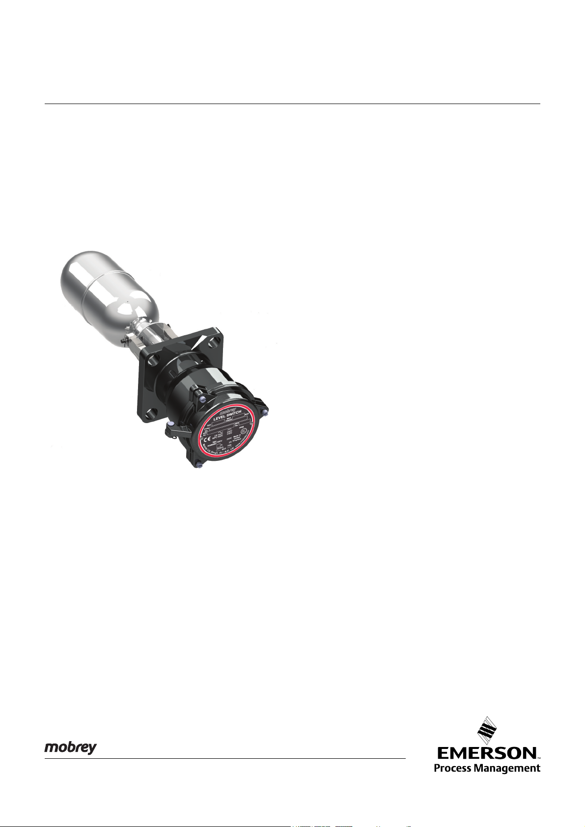
Horizontal Float Switch
Mobrey Magnetic Level Switches
Functional Safety Manual
www.mobrey.com
Page 2

Page 3

Functional Safety Manual
M310/FSM, Rev AA
Horizontal Float Switch
January 2012
Contents
Introduction Scope and Purpose of the Safety Manual ...........................................................page 3
Skill Level Requirement .......................................................................................page 3
Terms, Abbreviations, And Acronyms ..................................................................page 3
Documentation and Standards.............................................................................page 5
Product Description Level Switch Purpose ..........................................................................................page 6
Operation Principle ..............................................................................................page 6
Ordering Information ............................................................................................page 7
Designing A Safety
Function Using The
Level Switch
Installation And
Commissioning
Operation And
Maintenance
Safety Function ....................................................................................................page 8
Environmental Limits............................................................................................page 8
Application Limits .................................................................................................page 8
Design Verification ...............................................................................................page 8
SIL Capability.......................................................................................................page 9
Connection of the Level Switch to the SIS Logic Solver ....................................page 10
General Requirements .......................................................................................page 10
Installation..........................................................................................................page 10
Physical Location And Placement...................................................................... page 10
Electrical Connections .......................................................................................page 10
Proof-test Requirement...................................................................................... page 11
Repair and Replacement ................................................................................... page 11
Notification Of Failures....................................................................................... page 11
Useful Lifetime Useful Life ..........................................................................................................page 12
Proposed Proof-test
Procedure
Suggested Proof-test ......................................................................................... page 13
Proof Test Coverage .......................................................................................... page 13
Level Switches Certified
to IEC 61508
2
Level Switches for General Purpose Applications (Stainless Steel Wetside)..... page 14
Level Switches for General Purpose Applications (Stainless Steel Wetside)..... page 14
Level Switches for General Purpose Applications (Aluminum Bronze Wetside) page 15
Page 4

Functional Safety Manual
IP101/FSM, Rev AA
January 2012
Horizontal Float Switch
Magnetic Level Switch Functional Safety Manual
INTRODUCTION
Scope and Purpose of
the Safety Manual
This safety manual contains the information to design, install, verify and maintain a
Safety Instrumented Function (SIF) utilizing the Mobrey magnetic level switch.
The manual provides the necessary requirements to enable the integration of the
horizontal point-level float switch when showing compliance with the IEC 61508 or
IEC 61511 functional safety standards. It indicates all assumptions that have been
made on the usage of the level switch. If these assumptions cannot be met by the
application, the Safety Integrity Level (SIL) capability of the product may be adversely
affected.
NOTE:
For product support, use the contact details on the back page.
Skill Level Requirement System design, installation and commissioning, and repair and maintenance shall be
carried out by suitably qualified personnel.
Terms, Abbreviations,
And Acronyms
Basic Safety
Freedom from unacceptable risk of harm.
BPCS
Basic Process Control System – a system which responds to input signals from the
process, its associated equipment, other programmable systems and/or an operator
and generates output signals causing the process and its associated equipment to
operate in the desired manner but which does not perform any safety instrumented
functions with a claimed SIL greater than or equal to 1.
Fail-safe State
State where switch output is in the state corresponding to an alarm condition. In this
condition the switch contacts will normally be open.
Fail Dangerous
Failure that does not respond to an input from the process (i.e. not switching to the
fail-safe state).
Fail Dangerous Detected
Failure that is dangerous but is detected.
Fail Dangerous Undetected
Failure that is dangerous and that is not detected.
Fail No Effect
Failure of a component that is part of the safety function but that has no effect on the
safety function.
Fail Safe
Failure that causes the switch to go to the defined fail-safe state without an input from
the process.
3
Page 5

Horizontal Float Switch
FIT
FIT is the abbreviation for Failure In Time. One FIT is 1x10⁻⁹ failure per hour
FMEDA
Failure Modes, Effects, and Diagnostics Analysis.
Functional Safety
Part of the overall safety relating to the process and the BPCS which depends on the
correct functioning of the Safety Instrumented System (SIS) and other protection
layers.
HFT
Hardware Fault Tolerance.
Low demand
Mode of operation, where the frequency of demands for operation made on a
safety-related system is no greater than twice the proof test frequency.
PFD
Average Probability of Failure on Demand.
Functional Safety Manual
M310/FSM, Rev AA
January 2012
AVG
SFF
Safe Failure Fraction – a fraction of the overall random failure rate of a device that
results in either a safe failure or a detected dangerous failure.
SIF
Safety Instrumented Function – a safety function with a specified SIL which is
necessary to achieve functional safety. Typically a set of equipment intended to reduce
the risk due to a specified hazard (a safety loop).
SIL
Safety Integrity Level – a discrete level (one out of four) for specifying the safety
integrity requirements of the safety instrumented functions to be allocated to the safety
instrumented systems.
SIL 4 has the highest level of safety integrity, and SIL 1 has the lowest level.
SIS
Safety Instrumented System – an instrumented system used to implement one or
more safety instrumented functions. An SIS is composed of any combination of
sensors, logic solvers, and final elements.
4
Page 6

Functional Safety Manual
IP101/FSM, Rev AA
January 2012
Horizontal Float Switch
Documentation
and Standards
Table 1.
Associated Documentation
Table 2.
Associated Standards
This section lists the documentation and standards referred to by this safety manual.
Documents Purpose of Documents
IEC 61508-2: ed2, 2010 Functional Safety of Electrical/Electronic/Programmable
Electronic Safety-Related Systems
Exida EM 10/08-36 R001 FMEDA Report Version V1, Revision R2 for the
IP101 Mobrey magnetic level switch Product Data Sheet
M310 Mobrey magnetic level switch Instruction leaflet
Standards Purpose of Standards
IEC 61508: ed2, 2010 Functional Safety of electrical/electronic/programmable
IEC 61511
(ANSI/ISA 84.00.01-2004)
Mobrey magnetic level switch with a F84 Float
electronic safety-related systems
Functional safety - Safety instrumented systems for the
process industry sector
5
Page 7

Functional Safety Manual
s
N
s
N
Contact B-B
Contact A-A
Pushrods
Float
Magnet
Float
Cross-section of the Level Switch
M310/FSM, Rev AA
Horizontal Float Switch
January 2012
PRODUCT
DESCRIPTION
Level Switch Purpose Mobrey magnetic level switches are ideal for high and low liquid level alarm, overfill
alarm, and pump control duties.
Figure 1.
Application Example:
High and Low Level Alarm
Operation Principle The level switch is designed to open or close a circuit (“switch”) as a changing liquid
level within a vessel passes the level of the float (the Switch Point).
When the process fluid level is below the Switch Point, contacts B-B are made and
contacts A-A are open (Figure 2).
When the process fluid level is above the Switch Point, contacts A-A are made and
contacts B-B are open (Figure 3).
Figure 2.
Level Decreases –
Float Pivots Downwards
6
Page 8

Functional Safety Manual
s
N
s
N
Contact B-B
Contact A-A
Pushrods
Float
Magnet
Float
Cross-section of the Level Switch
IP101/FSM, Rev AA
January 2012
Horizontal Float Switch
Figure 3.
Level Increases –
Float Pivots Upwards
NOTE:
For all product information and documentation downloads, visit www.mobrey.com.
Ordering Information Level switch models fitted with options listed on pages 14 and 15 of this manual have
been externally assessed and certified to IEC 61508.
A copy of the third party SIL certificate can be ordered from Mobrey (accessory model
code L2049).
7
Page 9

Functional Safety Manual
M310/FSM, Rev AA
Horizontal Float Switch
January 2012
DESIGNING A SAFETY
FUNCTION USING THE
LEVEL SWITCH
Safety Function A change in liquid level through the operating range of the float causes the switch to
operate. It may be used in high level or low level safety related applications. In either
case, it is recommended to use the set of contacts (A-A or B-B) which are Open in the
Fail Safe State.
Environmental Limits The designer of the SIF (Safety Instrumented Function) must check that the level
switch is rated for use within the expected environmental limits. See the Mobrey
product data sheet IP101 for environmental limits.
NOTE:
For all product information and documentation downloads, see www.mobrey.com.
Application Limits It is very important that the SIF designer checks for material compatibility by
considering process liquids and on-site chemical contaminants. If the Mobrey level
switch is used outside the application limits or with incompatible materials, the
reliability data and predicted SIL capability becomes invalid.
The construction materials of a Mobrey level switch are specified in the product data
sheet and the product reference manual (see Table 1 on page 5).
Use the model code on the product label and the ordering information table and
specification in these product documents to find out the construction materials.
Design Verification A detailed Failure Modes, Effects and Diagnostics Analysis (FMEDA) report for the
Mobrey magnetic level switch is available to download from the web sites
www.mobrey.com and www.mobrey.com. The FMEDA report details all failure rates
and failure modes as well as expected lifetime.
NOTE:
The FMEDA report is available from the Safety quick link at www.mobrey.com.
In the right-hand panel, there are SIL documents including the FMEDA report.
The achieved Safety Integrity Level (SIL) of an entire Safety Instrumented Function
(SIF) design must be verified by the designer using a PFD
the architecture, proof test interval, proof test effectiveness, any automatic diagnostics,
average repair time, and the specific failures rates of all equipment included in the SIF.
Each subsystem must be checked to assure compliance with minimum Hardware
Fault Tolerance (HFT) requirements. When using the Mobrey level switch in a
redundant configuration, a common cause factor of at least 5% should be included in
the safety integrity calculations.
The failure rate data listed in the FMEDA report is only valid for the useful lifetime of
the Mobrey level switch. The failure rates increase after this useful lifetime period has
expired. Reliability calculations based on the data listed in the FMEDA report for
mission times beyond the lifetime may yield results that are too optimistic, i.e. the
calculated SIL will not be achieved.
calculation considering
AVG
8
Page 10

Functional Safety Manual
IP101/FSM, Rev AA
January 2012
SIL Capability Systematic Integrity
The Mobrey level switch has met manufacturer design process requirements of
Safety Integrity Level 2 (SIL 2). These are intended to achieve sufficient integrity
against systematic errors of design by the manufacturer.
A Safety Instrumented Function (SIF) designed with the Mobrey level switch must not
be used at a SIL higher than the statement without “prior use” justification by the
end-user, or verification of diverse technology in the design.
Random Integrity
The Mobrey level switch is classified as a type A device according to Table 2 of the
standard IEC 61508-2. Therefore, based on an Safe Failure Fraction (SFF) of between
0% and 60%, a design can meet SIL 1 with Hardware Fault Tolerance (HFT) = 0 and
SIL 2 with HFT = 1 when the level switch is used as a single component in a sensor
subsystem.
Safety Parameters
The failure rates given here are valid for the useful lifetime of the product, as described
in the section “Useful Lifetime” on page 12.
NOTE:
The FMEDA report is available from the Safety quick link at www.mobrey.com.
In the right-hand panel, there are SIL documents including the FMEDA report.
Horizontal Float Switch
Table 3.
Failure Rates for Level Switch
4-contact Versions – Types D and P
Table 4. Failure Rates for Level
Switch 6-contact Versions –
Types D6, P6, H6, and B6
Table 5.
Failure Rates according to
IEC 61508, 4-contact Versions –
Types D and P (FIT)
Failure Rate (FIT)
Failure Category
Fail Safe Detected 0 0
Fail Safe Undetected 87 89
Fail Dangerous Detected 0 0
Fail Dangerous Undetected 195 193
Residual 34 34
(1) FIT is the abbreviation for Failure In Time. One FIT is 1x10⁻⁹ failure per hour.
Failure Category
Fail Safe Detected 0 0
Fail Safe Undetected 167 169
Fail Dangerous Detected 0 0
Fail Dangerous Undetected 275 273
Residual 34 34
(1) FIT is the abbreviation for Failure In Time. One FIT is 1x10⁻⁹ failure per hour.
Device
Maximum Detection 0 87 0 195 30.9
Minimum Detection 0 89 0 193 31.6
(1) FIT is the abbreviation for Failure In Time. One FIT is 1x10⁻⁹ failure per hour.
Maximum Detection Minimum Detection
Failure Rate (FIT)
Maximum Detection Minimum Detection
SD
(1)
SU
(1)
(1)
DD
SFF %
DU
Table 6.
Failure Rates according to
IEC 61508, 6-contact Versions –
Types D6, P6, H6, and B6 (FIT)
Device
Maximum Detection 0 167 0 275 37.8
Minimum Detection 0 169 0 273 38.3
(1) FIT is the abbreviation for Failure In Time. One FIT is 1x10⁻⁹ failure per hour.
SD
(1)
SU
DD
SFF %
DU
9
Page 11

Horizontal Float Switch
Functional Safety Manual
M310/FSM, Rev AA
January 2012
Connection of the Level
Switch to the SIS Logic
Solver
The Mobrey level switch should be connected to the safety-rated logic solver which is
actively performing the safety function as well as automatic diagnostics (if any)
designed to diagnose potentially dangerous failures within the level switch.
NOTE:
For all product information and documentation downloads, visit www.mobrey.com.
General Requirements • The system and function response time shall be less than the process safety time
The Mobrey level switch will move to its defined safe state in less than this time
with relation to the specific hazard scenario.
• All SIS components, including the Mobrey level switch, must be operational before
process start-up
• The user shall verify that the Mobrey level switch is suitable for use in safety
applications by confirming the float level switch nameplate and model number are
properly marked
• Personnel performing maintenance and testing on the Mobrey level switch shall
first be assessed as being competent to do so
• Results from periodic proof tests shall be recorded and periodically reviewed
• The Mobrey level switch shall not be operated beyond the useful lifetime as listed
on page 12 (and in the specification section of the product document M310)
without undergoing overhaul or replacement
INSTALLATION AND
COMMISSIONING
NOTE:
For all product information and documentation downloads, visit www.mobrey.com.
Installation The Mobrey level switch must be installed as described in the installation section of the
product instructions leaflet M310. Check that environmental conditions do not exceed
the ratings in the specification section.
The Mobrey level switch must be accessible for physical inspection.
Physical Location And
Placement
The Mobrey level switch shall be accessible with sufficient room for cover removal and
electrical connections, and allow for manual proof-testing to take place.
The switch point is determined by the location of the Mobrey level switch, and
consideration must be given to allow the safe proof-testing of the level switch by
forcing liquid to put the switch into its Fail-Safe state.
Electrical Connections Wiring should be adequately rated and not be susceptible to mechanical damage.
Electrical conduit is commonly used to protect wiring.
10
Page 12

Functional Safety Manual
IP101/FSM, Rev AA
January 2012
Horizontal Float Switch
OPERATION AND
MAINTENANCE
Proof-test Requirement During operation, a low-demand mode SIF must be proof-tested. The objective of
proof-testing is to detect failures within the equipment in the SIF that are not detected
by any automatic diagnostics of the system. Undetected failures that prevent the SIF
from performing its function are the main concern.
Periodic proof-tests shall take place at the frequency (or interval) defined by the SIL
verification calculation. The proof-tests must be performed more frequently than or as
frequently as specified in the SIL verification calculation in order to maintain the
required safety integrity of the overall SIF. A sample procedure is provided in the
section “Proposed Proof-test Procedure” on page 13.
Results from periodic proof tests shall be recorded and periodically reviewed.
Repair and Replacement Repair procedures in the Mobrey product document M310 must be followed.
Notification Of Failures In case of malfunction of the system or SIF, the Mobrey level switch shall be put out of
operation and the process shall be kept in a safe state by other measures.
Mobrey Limited must be informed when the Mobrey level switch is required to be
replaced due to failure. The failure shall be documented and reported to Mobrey
Limited using the contact details on the back page of this safety manual. This is an
important part of Emerson Process Management’s SIS management process.
11
Page 13

Functional Safety Manual
M310/FSM, Rev AA
Horizontal Float Switch
January 2012
SPECIFICATIONS
Useful Life
USEFUL LIFETIME According to Section 7.4.9.5 of IEC 61508-2, a useful lifetime based on experience
should be assumed.
Although a constant failure rate is assumed by the probabilistic estimation method
(see FMEDA report), this only applies provided that the useful lifetime
components is not exceeded. Beyond their useful lifetime, the result of the probabilistic
calculation method is therefore meaningless as the probability of failure significantly
increases with time. The useful lifetime is highly dependent on the subsystem itself
and its operating conditions.
This assumption of a constant failure rate is based on the bathtub curve. Therefore, it
is obvious that the PFD
constant domain and that the validity of the calculation is limited to the useful lifetime of
each component.
Based on general field failure data and manufactures component data, a useful life
period of approximately 10 to 15 years is expected for the Mobrey level switch.
When plant experience indicates a shorter useful lifetime than indicated here, the
number based on plant experience should be used.
calculation is only valid for components that have this
AVG
(1)
of
12
(1) Useful lifetime is a reliability engineering term that describes the operational time interval
where the failure rate of a device is relatively constant. It is not a term which covers product
obsolescence, warranty, or other commercial issues.
Page 14

Functional Safety Manual
IP101/FSM, Rev AA
January 2012
Horizontal Float Switch
PROPOSED
PROOF-TEST
PROCEDURE
According to Section 7.4.3.2.2 (f) of the standard IEC 61508-2, proof-tests shall be
undertaken to reveal dangerous faults which are undetected by diagnostic tests. This
means that it is necessary to specify how dangerous undetected faults which have
been noted during the Failure Modes, Effects, and Diagnostic Analysis can be
detected during proof-testing.
Suggested Proof-test The suggested proof-tests (Tables 7 and 8) consist of switch operation tests in-situ.
Table 7.
Suggested Proof-test
(Low Level Alarm)
Table 8.
Suggested Proof-test
(High Level Alarm)
Step Action
1 Inspect the accessible parts of the level switch for any leaks or damage
2 Bypass the safety function and take appropriate action to avoid a false trip
3 Disable any filling mechanism and drain the vessel to force the switch to the
fail-safe state and confirm that the Safe State was achieved and within the
correct time. INDEPENDENT PRECAUTIONS MUST BE TAKEN TO ENSURE
THAT NO HAZARD CAN RESULT FROM THIS OPERATION.
4 Reinstate the filling mechanism so that the vessel refills and confirm that the
normal operating state of the switch was achieved.
5 Remove the safety function bypass and otherwise restore normal operation
Step Action
1 Inspect the accessible parts of the level switch for any leaks or damage
2 Bypass the safety function and take appropriate action to avoid a false trip
3 Disable any drain mechanism and fill the vessel to force the switch to the
fail-safe state and confirm that the Safe State was achieved and within the
correct time. INDEPENDENT PRECAUTIONS MUST BE TAKEN TO ENSURE
THAT NO HAZARD CAN RESULT FROM THIS OPERATION.
4 Reinstate the drain mechanism so that the vessel refills and confirm that the
normal operating state of the switch was achieved
5 Remove the safety function bypass and otherwise restore normal operation
Proof Test Coverage The Proof Test Coverage for the tests listed in the section “Proposed Proof-test
Procedure” may be considered to be 100%, covering all components of the Mobrey
level switch.
13
Page 15

Horizontal Float Switch
Functional Safety Manual
M310/FSM, Rev AA
January 2012
LEVEL SWITCHES
CERTIFIED TO IEC 61508
Tables 9, 10, and 11 lists all of the Mobrey magnetic level switch options that are
certified to IEC 61508. In general, this is the entire range with the exception of the
marine versions, pneumatic switch mechanisms, and some floats.
Refer to Mobrey product data sheet IP101 for the full specifications.
Table 9. Level Switches for General Purpose Applications (Stainless Steel Wetside)
Model Product Description
S Switch
Flange (Head) Flange (Head)
36 Mobrey A
190 Mobrey A
440 3 in. ASME B16.5 Class 150 RF
441 4 in. ASME B16.5 Class 150 RF
424 3 in. ASME B16.5 Class 300 RF
425 4 in. ASME B16.5 Class 300 RF
489 3 in. ASME B16.5 Class 600 RF
490 3 in. ASME B16.5 Class 900 RF
428 EN 1092-1 PN 16 (DN 65)
429 EN 1092-1 PN 16 (DN 80)
430 EN 1092-1 PN 16 (DN 100)
Switch Mechanism
D
P
D6
P6
H6 As Type D6 but with gold plated contacts and hermetically sealed moving parts
B6 As Type H6 but approved for Zone 2 areas
Enclosure / Housing
A Aluminum alloy
Float
F84 General purpose e.g. high/low alarm, 316 SST
F93
F96 General purpose e.g. high/low alarm, 316 SST
F98 General purpose e.g. high/low alarm, 316 SST
F104/+ Cranked arm: horizontal or vertical, 316 SST
F106 General purpose e.g. high/low alarm, 316 SST
F107 General purpose e.g. high/low alarm, 316 SST
Typical Model Number: S 36 D A / F84
Electrical: 2 independent Single Pole Single Throw (SPST) contact sets
As Type D but with gold plated contacts
Electrical: 2 independent circuits of double pole changeover contact sets
As Type D6 but with gold plated contacts
Shrouded for dirty liquids, 316 SST
431 EN 1092-1 PN 16 (DN 125)
417 EN 1092-1 DN 65 PN 40 (DN 65)
418 EN 1092-1 PN 40 (DN 80)
419 EN 1092-1 PN 40 (DN 100)
433 EN 1092-1 PN 40 (DN 125)
434 EN 1092-1 PN 40 (DN 150)
488 EN 1092-1 PN 63 (DN 80)
435 EN 1092-1 PN 63 (DN 100)
436 EN 1092-1 PN 63 (DN 125)
437 EN 1092-1 PN 63 (DN 150)
14
Page 16

Functional Safety Manual
IP101/FSM, Rev AA
January 2012
Table 10. Level Switches for General Purpose Applications (Aluminum Bronze Wetside)
Model Product Description
S Switch
Flange (Head)
01 Mobrey A flange
Switch Mechanism
DB Electrical: 2 independent Single Pole Single Throw (SPST) contact sets
PB As Type DB but with gold plated contacts
D6B Electrical: 2 independent circuits of double pole changeover contact sets
P6B As Type D6B but with gold plated contacts
Float
F84 General purpose e.g. high/low alarm, 316 SST
F93 Shrouded for dirty liquids, 316 SST
F104/+ Cranked arm: horizontal or vertical, 316 SST
Typical Model Number: S 01 DB / F84
Table 11. Level Switches for Hazardous Area Applications
Model Product Description
S Switch
Flange (Head)
250 Mobrey G, 316 Stainless Steel
275 Mobrey G, Gunmetal
256 3 in. ASME B16.5 Class 150 RF
257 4 in. ASME B16.5 Class 150 RF
278 6 in. ASME B16.5 Class 150 RF
251 3 in. ASME B16.5 Class 300 RF
254 4 in. ASME B16.5 Class 300 RF
260 3 in. ASME B16.5 Class 600 RF
261 3 in. ASME B16.5 Class 900 RF
253 EN 1092-1 PN 40 (DN 80)
255 EN 1092-1 PN 40 (DN 100)
269 EN 1092-1 PN 40 (DN 125)
272 EN 1092-1 PN 63 (DN 80)
268 EN 1092-1 PN 63 (DN 100)
270 EN 1092-1 PN 63 (DN 125)
271 EN 1092-1 PN 63 (DN 150)
Switch Mechanism
D Electrical: 2 independent Single Pole Single Throw (SPST) contact sets
P As Type D but with gold plated contacts
D6 Electrical: 2 independent circuits of double pole changeover contact sets
P6 As Type D6 but with gold plated contacts
H6 As Type D6 but with gold plated contacts and hermetically sealed moving parts
Enclosure / Housing
A Aluminum alloy
G Gunmetal
X Use ‘AX’ or ‘GX’ for applications with ambient temperatures –4 to –76 °F (–20 to –60 °C)
Float
F84 General purpose e.g. high/low alarm, 316 SST
F185 General purpose e.g. high/low alarm, Alloy 400
F96 General purpose e.g. high/low alarm, 316 SST
F98 General purpose e.g. high/low alarm, 316 SST
F104/+ Cranked arm: horizontal or vertical, 316 SST
F106 General purpose e.g. high/low alarm, 316 SST
F107 General purpose e.g. high/low alarm, 316 SST
Typical Model Number: S 250 D A / F84
Horizontal Float Switch
15
Page 17

Horizontal Float Switch
Emerson provides a wide range of Mobrey products for level measurement applications.
Functional Safety Manual
M310/FSM, Rev AA
January 2012
Mobrey Level Solutions
POINT LEVEL DETECTION
Vibrating Fork Liquid Level Switches
For high and low alarms, overfill protection, pump control,
including wide pressure and temperature requirements, and
hygienic applications. Flexible mounting. Immune to changing
process conditions and suitable for most liquids.
• Mobrey Mini-Squing (Compact)
• Mobrey Squing 2 (Full-featured)
Ultrasonic Gap Sensor Liquid Level Switches
For use in non-hazardous industrial processes to detect high or
low liquid levels and liquid interface. Immune to changing
density, and wide dielectric and pH variations. Suitable for use in
most clean and non-aerated liquids, with options for sludges and
slurries.
Float and Displacer Liquid Level Switches
Mobrey electromechanical float and displacer level switches are
ideal for alarm and pump control duties, especially in critical
applications or hazardous areas.
• Mobrey Horizontal Level Switches
• Mobrey Vertical Level Switches
Chambers are available for external mounting of these level
switches on process vessels.
Dry Products Level Switches
For high and low level alarms. Including threaded mounting
connections, extended lengths, high temperature capability, and
multiple detection techniques. Suitable for a wide variety of
powders, granules, and free flowing solids with wide variations in
bulk densities.
• Mobrey VLS Series – Vibrating Rod Level Switch
• Mobrey PLS Series – Paddle Level Switch
CONTINUOUS MEASUREMENT
Ultrasonic Continuous Level Transmitters and Controllers
Top mounted, non-contacting for simple tank and open-air
process level measurements. Unaffected by fluid properties such
as density, viscosity, dirty coating, and corrosiveness. Intrinsically
Safe versions are available for operating in hazardous areas.
• Mobrey MSP Series Ultrasonic Level and Flow Transmitters
• Mobrey MCU900 Series Universal Controllers
Ultrasonic Sludge Density Blanket Monitoring and Control
Ultrasonic in-line pipe or tank mounted sensors for sludge density
measurement and control, and top mounted ultrasonic sensors for
continuous measurement of sludge blanket level in Industrial and
Municipal effluent treatment processes.
• Mobrey MSM400 – Sludge Density Monitor
• Mobrey MSL600 – Sludge Blanket Level Monitor
Displacer Continuous Level Measurement
Top mounted in a vessel or externally mounted in a vertical
chamber. For use in hazardous areas.
• Mobrey MLT100 – Displacer Level Transmitter
Hydrostatic Continuous Level Transmitter
For level measurements in non-pressurized tanks where in-tank
problems such as foaming, vapor layers, and temperature
gradients prohibit the use of other instrumentation.
• Mobrey 9700 Series hydrostatic electronic level transmitters
SPECIALIZED CONDUCTIVITY
Conductivity Water and Steam Interface Monitoring
Steam/water interface level gauges using specialized, high
performance conductivity probes in external columns and
manifolds, ideal for steam plants where reliable and redundant
indication of boiler water level and turbine protection is critical.
• Hydratect 2462 – Water/Steam detection Systems
• Hydrastep 2468 – Water/Steam Monitoring Systems
The Emerson logo is a trade
Rosemount
Mobrey is a registered tradema
All other marks are the property of
We reserve the right to modify or improve the designs or specifications of product and services at any time without notice.
© 2012 Mobrey Ltd. All rights reserved.
International:
Emerson Process Management
Mobrey Ltd.
158 Edinburgh Avenue
Slough, Berks, SL1 4UE, UK
T +44 (0)1753 756600
F +44 (0)1753 823589
www.mobrey.com
M310/FSM Rev AA 01/12
is a registered trademark of Rosemount Inc.
mark and service mark of Emerson Electric Co.
rk of Mobrey Ltd.
their respective owners.
Americas:
Emerson Process Management
Rosemount Measurement
8200 Market Boulevard
Chanhassen, MN 55317 USA
T (U.S.) 1-800-999-9307
T (International) +1 952 906 8888
F +1 952 906 8889
 Loading...